1
INSTALLATION AND SET-UP MANUAL
C3 MAESTRO™ DISPATCH CONSOLE FOR WINDOWS NT®
WITH ENHANCED AUDIO ENCLOSURE
TABLE OF CONTENTS
Page
GENERAL.......................................................................................................................................................
PERSONAL COMPUTERS ...................................................................................................................
Hardware.............................................................................................................................................
Software..............................................................................................................................................
5
6
6
6
BOARD SET-UP .............................................................................................................................................
ENHANCED AUDIO ENCLOSURE.....................................................................................................
Audio System Board ...........................................................................................................................
Mic Audio ALC Enable/Disable DIP Switch (S1).......................................................................
Digital Potentiometers’ Settings ..................................................................................................
SPEAKER ASSEMBLY..........................................................................................................................
Speaker Amp Board............................................................................................................................
Minimum Volume Level DIP Switch (SW1 Position 1)..............................................................
Maximum Volume Level DIP Switch (SW1 Position 2) .............................................................
RS-422 BOARD........................................................................................................................................
6
6
6
6
7
7
7
8
8
8
INTERCONNECTING THE EQUIPMENT ................................................................................................
CEC/IMC INTERCONNECTIONS.......................................................................................................
Control Data Link ...............................................................................................................................
Overview .....................................................................................................................................
RS-422 Interfacing (Co-Located Hook-Ups)...............................................................................
RS-232 Interfacing (Remote Console Hook-Ups Via 4-Wire Modems And RS-232
Interconnections) .........................................................................................................................
ZyXEL Modem Configuration.....................................................................................................
Other Modems .............................................................................................................................
Audio Links ........................................................................................................................................
PERSONAL COMPUTER......................................................................................................................
PC-To-Enhanced Audio Enclosure Serial Data Interconnect Cable ...................................................
Standard PC Keyboard........................................................................................................................
Mouse (Or Other Pointing Device).....................................................................................................
Video Display Monitor .......................................................................................................................
ENHANCED AUDIO ENCLOSURE.....................................................................................................
Dispatch Keyboard (if used) ...............................................................................................................
Desk Mic (if used) .............................................................................................................................
Headset Jacks (if used) .......................................................................................................................
Boom/Gooseneck Mic (if used) ..........................................................................................................
Footswitches (if used) .........................................................................................................................
Speakers (if used)................................................................................................................................
Recorder Outputs (if used)..................................................................................................................
External Paging Encoder Input (if used).............................................................................................
11
11
12
12
12
ericssonz
14
14
15
16
23
23
23
23
23
23
23
23
24
24
24
25
25
25
AE/LZB 119 1894 R1A
TABLE OF CONTENTS
Page
Relay Outputs (if used) .......................................................................................................................
Call Director (if equipped) ..................................................................................................................
Console-to-CEC/IMC Audio Interconnections ............................................................................
Console-to-Call Director Interconnections ..................................................................................
EQUIPMENT ROOM GROUNDING ...................................................................................................
ELECTROSTATIC DISCHARGE (ESD) PROTECTION..................................................................
AC POWER AND UPS EQUIPMENT ..................................................................................................
26
26
26
28
28
28
28
ENHANCED AUDIO ENCLOSURE PIN-OUTS ........................................................................................ 28
AUDIO TOWER REPLACEMENT.............................................................................................................. 33
POWER-UP PROCEDURE ........................................................................................................................... 36
SHUT-DOWN PROCEDURE........................................................................................................................ 36
SOFTWARE INSTALLATION..................................................................................................................... 36
CONSOLE APPLICATION.................................................................................................................... 36
UDS CONFIGURATOR PROGRAM.................................................................................................... 36
SOFTWARE SET-UP PROCEDURE ...........................................................................................................
PC CMOS SET-UP PROGRAM ............................................................................................................
Hewlett-Packard PCs ..........................................................................................................................
Other PCs ............................................................................................................................................
STARTING WITH THE FACTORY DEFAULT CONFIGURATION..............................................
Booting-Up The PC With Windows NT .............................................................................................
Initial Hardware-Related Settings .......................................................................................................
Via Configuration Editor .............................................................................................................
Via Windows NT (Verifying FIFO Is Enabled)...........................................................................
Starting The Console Application .......................................................................................................
Database Initialization.........................................................................................................................
Sending Console User Profiles (“Setups”)...................................................................................
Sending Console Hardware Configuration...................................................................................
System Manager Database Transfers ...........................................................................................
Console Privilege Lists ................................................................................................................
Saving Database Information .......................................................................................................
ADVANCED CONFIGURATIONS AND FEATURE LICENSED OPTIONS..................................
Windows NT-Related Advanced Configuration .................................................................................
Dual-Boot Capabilities.................................................................................................................
User Accounts..............................................................................................................................
Automatic Vs. Manual User Log-On ...........................................................................................
Monitor Video Resolution And Colors ........................................................................................
Touch-Screen Monitors................................................................................................................
Networking And Computer Naming ............................................................................................
Feature Licensed Options.............................................................................................................
Printers.........................................................................................................................................
Console Application-Related Advanced Configuration ......................................................................
Start-Up Options ..........................................................................................................................
Changes Via The Configuration Editor Program .........................................................................
Changes Via The UDS Configurator Program (Optional) ...........................................................
Feature Licensed Options....................................................................................................................
CEC/IMC Auxiliary Input/Output (I/O).......................................................................................
Integrated Paging .........................................................................................................................
Radio Status Message (RSM) and Request-To-Tak (RTT) .........................................................
Copyright © August 1996, Ericsson Inc.
2
37
37
37
37
37
37
38
38
39
39
40
40
41
41
42
42
42
42
42
42
43
43
43
43
43
44
44
44
44
45
46
47
48
48
AE/LZB 119 1894 R1A
TABLE OF CONTENTS
Page
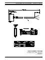
CABLE ASSEMBLY DIAGRAMS
CONTROL DATA CABLE (100-FOOT) 19B804083P3 ...................................................................... 21
AUDIO CABLE (100-FOOT) 19B804083P2 ......................................................................................... 22
TABLES
Table 1 − Approved Personal Computers ...........................................................................................
Table 2 − Audio System Board Mic Audio ALC Enable/Disable DIP Switch S1 ..............................
Table 3 – SW1 Selection Definitions..................................................................................................
Table 4 – Digital Potentiometers ........................................................................................................
Table 5 - Standard Serial COM Port Utilization.................................................................................
Table 6 – Cable 19B804083P3 Color Coding ....................................................................................
Table 7 − C3 Maestro-To-CEC/IMC Audio Line Requirements ........................................................
Table 8 − Boom/Gooseneck Mic Wiring* ..........................................................................................
Table 9 − Enhanced Audio Enclosure-To-CEC/IMC Call Director Audio Signal Descriptions.........
Table 10 − Enhanced Audio Enclosure-To-Call Director Control & Audio Signal Descriptions.......
Table 11 – CEC/IMC Audio Lines (female DB-25 labeled "LINES 1-4")........................................
Table 12 – Call Director (female DB-9 labeled "CALL DIR") ..........................................................
Table 13 – Boom/Gooseneck Microphone (female DB-9 labeled "B/G MIC") .................................
Table 14 – Desk Microphone (female DB-9 labeled "DESK MIC")..................................................
Table 15 – Operator Headset (female DB-9 labeled "OPER H/S")....................................................
Table 16 – Supervisor Headset (female DB-9 labeled "SUPER H/S")...............................................
Table 17 – Select Speaker (male DB-9 labeled "SEL SPKR")...........................................................
Table 18 – Unselect Speakers –Three Total (male DB-9 labeled "UNSEL SPKRx"*)......................
Table 19 – Operator Footswitch (female DB-9 labeled "OPER FT. SW.")........................................
Table 20 – Supervisor Footswitch (female DB-9 labeled "SUPER FT. SW.") ..................................
Table 21 – Optional RS-422 Input/Output (female DB-9 labeled "I/O") ...........................................
Table 22 – Personal Computer RS-232 Input/Output (female DB-9 labeled "PC") ...........................
Table 23 – Dispatch Keyboard Serial Input/Output (female DB-9 labeled "KBD") ..........................
Table 24 – Relay Connections (18-position terminal block labeled "RELAYS") ..............................
Table 25 – Pager Input (4-position terminal block labeled "PAGING") ............................................
Table 26 – Recorder Outputs (4-position terminal block labeled "RECORDER") ............................
Table 27 – Auxiliary Audio Inputs (Not Supported) (1/8-inch phone jack labeled "AUX. IN")........
Table 28 – Dispatch Keyboard Cable Color Coding ..........................................................................
Table 29 – CEC/IMC Manager Operations Guide Publication Numbers ...........................................
6
6
8
9
12
13
17
24
27
27
28
30
30
30
30
31
31
31
31
32
32
32
32
33
33
33
33
35
40
FIGURES
Figure 1 – C3 Maestro With Enhanced Audio Enclosure Equipment Interconnections .....................
Figure 2 − Audio System Board DIP Switch S1 Factory Setting (ALC Enabled On All Mics)..........
Figure 3 − Speaker Amp Board SW1 Factory Setting ........................................................................
Figure 4 – Plug-In RS-422 Board DB-25 Connector Pin-Out (B&B Electronics 3PXOCC1A).........
Figure 5 – Plug-In RS-422 Board DB-9 Connector Pin-Out (B&B Electronics 3PXCC2A) .............
Figure 6 − Audio Line Input And Output Connections At Enhanced Audio Enclosure......................
Figure 7A − CEC/IMC-To-C3 Maestro Interconnections (Co-Located) ............................................
Figure 7B − CEC/IMC-To-C3 Maestro Interconnections (Remote And/Or RS-232).........................
Figure 7C − Field-Fabricated Adapter ................................................................................................
Figure 8 – Recorder Outputs At Enhanced Audio Enclosure..............................................................
Figure 9 – Pager Inputs At Enhanced Audio Enclosure......................................................................
Figure 10 – Relay Terminal Block At Enhanced Audio Enclosure.....................................................
Figure 11 − Call Director Interface Connector At Enhanced Audio Enclosure ..................................
Figure 12 – Enhanced Audio Enclosure Rear Panel Connectors ........................................................
5
6
8
13
14
17
18
19
20
25
26
26
27
29
3
AE/LZB 119 1894 R1A
(This Page Intentionally Blank)
Copyright © August 1996, Ericsson Inc.
4
GENERAL
350A1371P8, and rack-mount
350A1371P11 — P12.
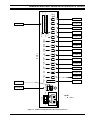
GENERAL
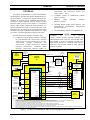
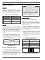
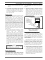
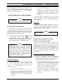
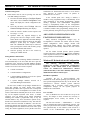
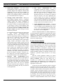
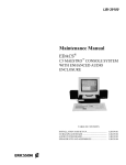
The purpose of this manual is to guide field installation
and maintenance personnel through the installation and setup of an EDACS® C3 Maestro™ dispatch console for the
Windows NT operating system. Installation and set-up of a
C3 Maestro console equipped with an Enhanced Audio
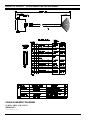
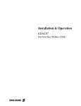
Enclosure audio system is covered. Figure 1 is a simplified
diagram which indicates equipment interconnections in a
typical installation of this type. As noted in the figure, some
installations may not require all interconnections shown and
still others may require additional interconnections to audio
accessories or optional equipment not shown in the figure.
•
•
•
•
TOUCHSCREEN DATA
(OPTIONAL)
COM2 (OR
PC BUS)
COM3
POINTING DEVICE
(MOUSE/TRACK-BALL)
DISPATCH
KEYBOARD
("CUSTOM
ENHANCED AUDIO ENCLOSURE
SEE
NOTE 8.
KBD
I/O BACKPLANE BOARD
AUDIO
SYSTEM
BOARD
KEYBOARD")
SEE
NOTE 8.
PC
LINES
1-4
LINE 1 IN
SELECT
SPEAKER
SEL SPKR
LINE 1 OUT
LINE 2 IN
SEE NOTE 3.
UNSELECT
SPEAKER 1
UNSEL
SPKR1
LINE 3 IN
LINE 4 IN
LINE 4 OUT
OPERATOR
HEADSET
CALL
DIR
CD OUT
DESK MIC
OPER
FT.SW.
Enclosure
firmware
CEC/IMC Digital Audio Switch firmware 5.0x
(344A3564G12, 344A3565G12, 344A3567G12
and 344A3568G12)
CEC/IMC Manager software 5.x (for Windows NT)
CABLE
19B804083P3
CEC/IMC
DIGITAL AUDIO SWITCH
TO/FROM OTHER
CEC/IMC
INTERFACE
MODULES
RS-232
(3 WIRES)
4-WIRE DATA
MODEM
EQUIPMENT
(REQUIRED FOR RS-232
A REMOTE
(3 WIRES)
CONSOLE)
CABLE
350A1371P29
(P29/5010150000)
RS-232
CONTROL
DATA
GSC CONTROL
DATA
DATA
CON.
CARD
TDM AUDIO
CIM
CONTROLLER
BOARD
(SEE NOTE 2)
SEE
NOTES 2 & 9.
CABLE
19B804083P2
SELECT AUDIO
(2 WIRES)
MIC AUDIO
(2 WIRES)
UNSELECT AUDIO 1
(2 WIRES)
UNSELECT AUDIO 2
(2 WIRES)
UNSELECT AUDIO 3 OR
CD PATCHED RADIO AUDIO
(2 WIRES)
CD PATCHED MIC AUDIO OR
CONSOLE MIC AUDIO
(2 WIRES)
LOCAL CNTRL
AUDIO
CON.
CARD
CIM
AUDIO
BOARD
(SEE NOTE 2)
LINE 1 OUT
LINE 1 IN
LINE 2 OUT
LINE 3 OUT
LINE 4 OUT
LINE 4 IN
SEE NOTES
6, 7 & 9.
SEE NOTES 4 & 5.
OPERATOR
FOOTSWITCH
Enhanced
Audio
RON 107 781 R2A
RS-422 (4 WIRES)
OPER H/S
DESK MIC
C3 Maestro console for Windows NT software
LZY 213 759 R1A
CONTROL DATA
COM1
(NOT USED DURING
NORMAL DISPATCH
OPERATIONS)
kits
C3 Maestro
for
Windows
NT
software
LZY 213 759 R1A requires CEC/IMC Controller and
Audio Board firmware 4.x or later, and CEC/IMC Manager software 4.x or later. In addition, CEC/IMC Controller Board firmware 5.x is required in the console’s
CIM and in the CEC/IMC MOM for some enhanced
functions to operate.
PERSONAL
COMPUTER
(PC)
STANDARD PC
KEYBOARD
speaker
NOTE
This document was developed in accordance with:
• C3 Maestro console primary hardware including
PC (with Windows NT) 350A1371P13, monitors
350A1371P14 (14-inch), 350A1371P15 (17-inch),
350A1371P16
(14-inch
touch-screen)
and
350A1371P33 (17-inch touch-screen), dispatch
keyboard
350A1371P17,
Enhanced
Audio
Enclosure 350A1371P4, desk-top speaker kit
VIDEO
DISPLAY
MONITOR
AE/LZB 119 1894 R1A
CD IN
CD HOOK/
SENSE
CD RECEIVER AUDIO
(2 WIRES)
CD MIC AUDIO
(2 WIRES)
CD CONTROL
(5 WIRES MAX.)
CALL
DIRECTOR
PHONE
LINES
SEE NOTE 7.
NOTES:
1. AC POWER CONNECTIONS NOT SHOWN.
2. PUNCH BLOCKS, TELCO CABLES, CEC/IMC BACKPLANE AND CONCENTRATOR CARD CABLES NOT INDICATED.
3. SPEAKERS INTERCONNECTED USING CABLE 350A1371P29 (P29/5010150000). ONE CABLE REQUIRED PER SPEAKER. ONLY ONE UNSELECT SPEAKER SHOWN.
4. SUPERVISOR HEADSET AND FOOTSWITCH, BOOM/GOOSENECK MIC, AND OTHER AUDIO INPUTS SUCH AS PAGER ARE NOT SHOWN.
5. RELAY OUTPUT AND DIGITAL INPUT CONNECTIONS ARE NOT SHOWN.
6. UNSELECT AUDIO LINE(S) NOT REQUIRED IF CONSOLE IS NOT EQUIPPED WITH RESPECTIVE UNSELECT SPEAKER(S).
7. IF CONSOLE SYSTEM DOES NOT SUPPORT CALL DIRECTOR TELEPHONE PATCH, ALL CD INTERCONNECTIONS ARE NOT REQUIRED.
8. ENHANCED AUDIO ENCLOSURE LABELING MATCHES OR APPROXIMATELY MATCHES REAR PANEL LABELING.
9. CABLE 19B804083P2 (LINE AUDIO) AND CABLE 19B804083P3 (RS-422 CONTROL DATA) PROVIDE ALL NECESSARY C3 MAESTRO-TO-CEC/IMC INTERCONNECTIONS WHEN CONSOLE IS
CO-LOCATED AND LESS THAN 100 FEET FROM CEC/IMC .
Figure 1 – C3 Maestro With Enhanced Audio Enclosure Equipment Interconnections
5
AE/LZB 119 1894 R1A
BOARD SET-UP
NOTE
IMPORTANT
NOTE
PERSONAL COMPUTERS
In most cases, changes to the factory DIP switch
and digital pot settings ARE NOT REQUIRED.
The following information lists the normal
factory settings and the optional settings which
are available. Digital pot setting changes must
be accomplished after most of the installation
procedures presented later in this manual are
complete and the console has been powered-up.
However, for completeness of this section, a
setting procedure is included on page 7.
Hardware
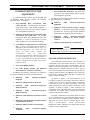
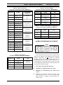
Table 1 lists the PCs approved for use with a
C3 Maestro for Windows NT. Use of an unapproved
computer will void the console system's warranty and
support services. Subsequent to the printing of this manual,
additional PCs not listed in the table may be approved.
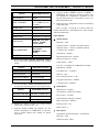
Table 1 − Approved Personal Computers
MANUFACTURER
Hewlett-Packard
Hewlett-Packard
Hewlett-Packard
MODEL NO. (TYPE)
Vectra VE Series 2 5/75
(Pentium/75 MHz)
Vectra VE 5/75
(Pentium/75 MHz)
Vectra VE2 5/100
(Pentium/100 MHz)
Software
The Personal Computer (PC) used with the C3 Maestro
console for Windows NT is delivered with its hard disk
drive formatted and Windows NT operating system software
installed. In most cases, MS-DOS is also installed and, in
this case, the PC is configured with dual-boot capability with
Windows NT being the default boot-up operating system.
MS-DOS is not required to run the C3 Maestro console for
Windows NT.
The C3 Maestro console application software is also
installed on the PC’s hard disk drive at the factory. The
console application software is also included with the
console equipment package on 3 ½-inch floppy disks in the
event software re-installation is required.
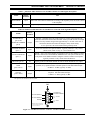
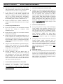
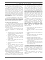
Audio System Board
Mic Audio ALC Enable/Disable DIP Switch (S1)
DIP switch S1 on the Audio System Board is used to
independently enable or disable each microphone's
automatic level control (ALC) circuit. The switch has four
(4) positions, one for each mic that may be connected to the
Enhanced Audio Enclosure.
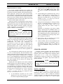
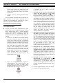
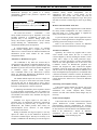
An Audio System Board ships from the factory with all
mic audio ALC circuits enabled. As shown in Figure 2, this
is accomplished by setting all four S1 switch positions to
"ON" or "CLOSED". Table 2 lists each switch position and
its corresponding microphone.
q
Normally, mic audio ALC should not be disabled.
However, if required, disable a mic's ALC by setting the
corresponding DIP switch position to "OFF" or
"OPEN". See manual AE/LZB 119 1892 for Enhanced
Audio Enclosure disassembly and Audio System Board
access instructions.
Table 2 − Audio System Board Mic Audio ALC
Enable/Disable DIP Switch S1
CAUTION
CAUTION
Always observe proper equipment handling
procedures to protect the equipment from ESD
damage. Refer to LBI-38737 for complete details.
BOARD SET-UP
ENHANCED AUDIO ENCLOSURE
Normally, the Enhanced Audio Enclosure is configured
at the factory for a standard C3 Maestro dispatch console
system installation. This configuration includes setting a
single 4-position DIP switch and programming all digital
pots for nominal audio input and output levels. The DIP
switch and digital pots within the Enhanced Audio
Enclosure are located on the Audio System Board.
6
S1 POSITION
MICROPHONE
1
Operator Headset
2
Desk
3
Boom/Gooseneck
4
Supervisor Headset
ON
1
2
3
4
Figure 2 − Audio System Board DIP Switch S1
Factory Setting (ALC Enabled On All Mics)
BOARD SET-UP
Digital Potentiometers’ Settings
To provide computer-controlled level settings, the
Enhanced Audio Enclosure's audio input and output circuits
incorporate 256-position digitally-controlled potentiometers.
These digital pots, located on the Audio System Board,
allow adjustment of the Enhanced Audio Enclosure's audio
levels via the PC. Adjustments include dispatcher-adjustable
audio levels such as headset sidetone volumes and systemlevel adjustments such as line input and output levels to and
from the CEC/IMC Digital Audio Switch.
With the exception of the dispatcher's headset sidetone
volume adjustments, none of the digital pots provide volume
adjustments for the speaker or headset earphone audio levels
during normal dispatch operations. Speaker and headset
volume adjustments are accomplished at the respective
speaker or headset via mechanical pots.
2.
Using the mouse, click Pots on the menu or simply
press <Alt> P on the PC keyboard. Either action
will display the Digital Pots Adjustment dialog
box.
3.
From the dialog box’s drop-down list box, select a
digital pot which requires a setting change. See
Table 4. The digital pot's existing setting is
displayed in the small text box. If a mouse is not
available, use the ↑ or ↓ arrow keys on the PC
keyboard for digital pot selection.
4.
Change the selected digital pot’s setting by clicking
the four (4) adjustment buttons as necessary. If a
mouse is not available, simply <Tab> to the
required button and press <Enter>. Repeat as
necessary.
Alternately, if restoration to the factory default
setting is required click the <Default> button. If a
mouse is not available, <Tab> to this button and
press the <Enter> key. Either action will cause the
pot’s EEPROM-stored factory default setting to be
copied as EEPROM-stored working setting. Other
pots’ settings are not altered.
5.
Repeat steps 3 and 4 as necessary for any other
digital pots which require setting changes.
6.
Click the <Done> button to exit the dialog box and
save changes. If a mouse is not available, <Tab> to
this button and press the <Enter> key. Changes are
saved in the EEPROM's working area as they are
made.
NOTE
NOTE
Communication module volume changes at the
C3 Maestro effect CEC/IMC CIM line output
levels, not the digital pots within the Enhanced
Audio Enclosure.
Fifteen (15) dual digital potentiometer chips (integrated
circuits) are located on the Audio System Board for a total
of thirty (30) individual pots; there are no mechanical
potentiometers. All audio level adjustments are
accomplished via software. See Table 4. A dispatcher may
adjust the operator's sidetone digital pot using dedicated
keyboard keystrokes <Alt> <Vol ↑ > and <Alt> <Vol ↓ > at
the Dispatch Keyboard or via pointing device (mouse/trackball/touch-screen) actions upon the console’s graphical user
interface.
AE/LZB 119 1894 R1A
SPEAKER ASSEMBLY
All of the digital pots initially power-up with the wiper
in a 50% or centered position. The microcontroller on the
Audio System Board then immediately loads each pot in
accordance with its respective setting stored in a "working"
area of a serial EEPROM chip on the board. The EEPROM
also contains an unchangeable "default" digital pot storage
area. When shipped from the factory, the working area
matches the default area.
Normally, a Speaker Assembly used with the Enhanced
Audio Enclosure is configured at the factory with its
minimum volume feature enabled and its maximum volume
output power set to 2 watts. This configuration is
accomplished by setting two positions on a 4-position DIP
switch located on the Speaker Amp Board within the
Speaker Assembly.
Digital pots can be adjusted via the console’s Dispatch
Manager program. This function changes the settings stored
in the EEPROM's working area. This function should only
be accomplished by well-trained installation and/or service
personnel. To change digital pots’ settings, the following
procedure may be performed after the console's installation
is complete, it is powered-up, the console application
software is executing, and the PC-to-Enhanced Audio
Enclosure serial data link is active:
The following information lists the normal factory
settings and the optional settings which are
available.
1.
At the standard PC keyboard, use one or more
Windows NT <Alt><Tab> keystrokes to switch to
the console’s Dispatch Manager program.
NOTE
NOTE
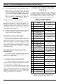
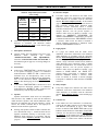
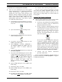
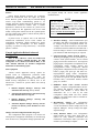
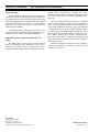
Speaker Amp Board
At each Speaker Assembly, a 4-position DIP switch
identified as SW1 is located on the Speaker Amp Board.
One position is used to enable or disable the minimum
volume level feature. A second position allows setting of the
maximum volume level to either 2 or 5 watts of output
7
AE/LZB 119 1894 R1A
BOARD SET-UP
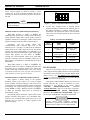
power. Factory settings are shown in Figure 3. These
switches have no effect on headset earphone output levels.
Currently, the other two DIP switch positions on SW1 are
not used.
ON
1
2
3
4
NOTE
NOTE
SW1 may have a tape seal placed over the switches
to prevent changes.
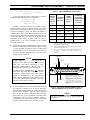
Minimum Volume Level DIP Switch (SW1 Position 1)
When SW1 position 1 is "OFF" or "OPEN", the
minimum volume level feature is enabled. This is the factory
setting. With this setting, audio from the speaker cannot be
completely turned off by rotating the volume control on the
Speaker Assembly's front panel fully counterclockwise.
Specifically, with the volume control fully
counterclockwise and a nomimal audio level of 436
millivolts rms at a frequency of 1kHz from the Enhanced
Audio Enclosure, the audio output level from the speaker
will not drop below approximately 0.38 milliwatts or 55
millivolts rms across the 8-ohm speaker. This wattage figure
assumes SW1 position 2 is also "OFF" or "OPEN",
selecting the 2-watt maximum volume level. With SW1
position 2 selecting 5-watts, the minimum volume level is
approximately 1.25 milliwatts or 100 millivolts across the 8ohm speaker.
When SW1 position 1 is "ON" or "CLOSED", the
minimum volume level feature is disabled and audio from
the speaker may be completely turned off by rotating the
volume control fully counterclockwise. This setting should
be used with caution since calls, especially calls on unselect
audio channels, are more likely to be missed.
Maximum Volume Level DIP Switch (SW1 Position 2)
SW1 position 2 allows setting of the speaker's
maximum volume level to either 2 or 5 watts of output
power. Normally, the factory setting is 2 watts. This level is
recommended, as it should be adequate in nearly all dispatch
environments. The 2-watt setting is selected by setting the
switch "OPEN" or "OFF". When the switch is "CLOSED"
or "ON", the maximum output power is increased to
approximately 5 watts.
Both wattage figures assume the volume control on the
Speaker Assembly's front panel is set at maximum (fully
clockwise) and a nominal audio signal input level of 436
millivolts rms at a frequency of 1 kHz is applied to the
Speaker Assembly.
8
Figure 3 − Speaker Amp Board SW1 Factory Setting
q
At this time, configure SW1 as required. Switch
position selections are defined in the following table. If
the Speaker Assembly is a desktop (with case) style,
disassemble it by removing the four (4) screws from the
back of the case and then separate the case's front and
rear sections.
Table 3 – SW1 Selection Definitions
SW1
POSITION
OPEN
(OFF)
CLOSED
(ON)
1
minimum volume
enabled *
minimum volume
disabled
2
2-watt maximum
speaker power *
5-watt maximum
speaker power
3
(not used) *
(not used)
4
(not used) *
(not used)
* OPEN (OFF) is factory setting for all SW1 positions.
RS-422 BOARD
Most PCs used with the console are factory-equipped
with a plug-in RS-422-capable board for serial control data
interfacing to the CIM within the CEC/IMC Digital Audio
Switch. In these cases, no changes to the related factory
set-ups are required assuming the factory-installed RS-422
board is utilized for CIM interfacing.
If the factory installed RS-422 board is not used or not
present within the PC, it may be beneficial to review
information in this manual in the section entitled
“CEC/IMC
subsection
INTERCONNECTIONS”,
“Control Data Link” (page 12) at this time. If necessary,
also see “SOFTWARE SET-UP PROCEDURE”,
subsection “PC CMOS SET-UP PROGRAM” (page 37)
for serial port enable/disable configuration information.
CAUTION
CAUTION
Always observe proper equipment handling
procedures to protect the equipment from ESD
damage. Refer to LBI-38737 for complete details.
BOARD SET-UP
AE/LZB 119 1894 R1A
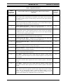
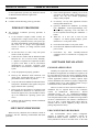
Table 4 – Digital Potentiometers
AUDIO
SYSTEM BD.
POT NO.
ENHANCED AUDIO ENCLOSURE AUDIO CIRCUIT LOCATED IN /
ADJUSTS *
TYPICAL
SETTING
**
1
Call Director Input — Adjusts level of telephone line audio from Call Director.
Affects audio levels to operator/supervisor headsets, select speaker, select recorder and
line output to CIM line input (to radio) during Call Director radio patch operations.
Also see pot 14.
120
28
Pager Input — Adjusts level of pager input audio from an external pager. Affects tone
levels to operator/supervisor headsets, select speaker, select recorder and line output to
CIM line input (to radio) during pager activations (PTTs).
130
3
Operator Headset Mic Input — Adjusts level of operator headset mic input audio.
Does not affect boom/gooseneck mic or desk mic audio input levels.
75
8
Selected Operator Mic Input — Adjusts currently selected operator mic (either
boom/gooseneck, desk or operator headset) audio level. In the circuitry, this adjustment
is located after pots 3, 5 and 6. Affects audio level(s) at one or more outputs including
line 1, line 4, select recorder and/or sidetone.
140
6
Desk Mic Input — Adjusts level of desk mic input audio. Does not affect
boom/gooseneck mic or operator headset mic audio input levels.
85
5
Boom/Gooseneck Mic Input — Adjusts level of boom/gooseneck mic input audio.
Does not affect operator headset mic or desk mic audio input levels.
124
4
Supervisor Headset Mic Input — Adjusts level of supervisor headset mic input audio.
Also see pot 7.
75
7
Supervisor Headset Mic Input — Post adjustment for supervisor headset mic input
audio. Do not change from factory setting. Also see pot 4.
140
9
Supervisor Sidetone — Adjusts sidetone level of supervisor headset mic audio applied
to supervisor and operator headset earphones.
31
10
Operator Sidetone — Adjusts sidetone level of operator headset mic audio applied to
supervisor and operator headsets earphones.
31
11
Line 1 Input — Adjusts level of line 1 input audio from CIM line 1 output. Affects
audio level to select audio output devices such as headset earphones, select speaker and
select recorder.
75
12
Line 2 Input — Adjusts level of line 2 input audio from CIM line 2 output. Affects
audio level to unselect audio output devices such as unselect speaker 1 and unselect
recorder.
75
17
Line 3 Input — Adjusts level of line 3 input audio from CIM line 3 output. Affects
audio level to unselect audio output devices such as unselect speaker 2 and unselect
recorder.
75
18
Line 4 Input — Adjusts level of line 4 input audio from CIM line 4 output (from
radio). Affects audio levels applied to unselect audio output devices such as unselect
recorder and, if a third unselect speaker is employed, unselect speaker 3. If a Call
Director is employed, adjustment affects audio to Call Director telephone line and
unselect recorder. Primary line 4 adjustment. Also see pots 2 and 20.
75
9
AE/LZB 119 1894 R1A
BOARD SET-UP
Table 4 – Digital Potentiometers (Continued)
AUDIO
SYSTEM BD.
POT NO.
ENHANCED AUDIO ENCLOSURE AUDIO CIRCUIT LOCATED IN /
ADJUSTS *
TYPICAL
SETTING
**
20
Auxiliary Input — Adjusts level of line 4 input audio from CIM line 4 output (from
radio). Affects audio levels applied to select recorder, and all speakers during Call
Director patch operations. Secondary line 4 adjustment used only if console is equipped
with a Call Director. Also see pot 18.
27
N/A (pot not used)
0
15
Line 1 Output — Adjusts level of line 1 output audio to CIM line 1 input.
23
16
Line 2 Output (adjustment never required)
23
13
Line 3 Output (adjustment never required)
23
14
Line 4 Output — Adjusts level of line 4 output audio to CIM line 4 input. Affects
audio level to patched radio during Call Director patch operations. Also see pot 1.
23
21
Select Recorder Output — Adjusts level of audio applied to the select recorder.
175
19
Select Audio Output — Adjusts level of audio at an internal Enhanced Audio
Enclosure reference point on Audio System Board. Affects select speaker, select
recorder, operator headset earphone and supervisors headset earphone audio levels.
190
29
Select Speaker Output — Adjusts level of audio applied to the select speaker. This pot
is not used as a volume control.
128
30
Unselect Speaker 1 Output — Adjusts level of audio applied to the first unselect
speaker (unselect speaker 1). This pot is not used as a volume control.
128
23
Unselect Speaker 2 Output — Adjusts level of audio applied to the second unselect
speaker (unselect speaker 2). This pot is not used as a volume control.
128
24
Unselect Speaker 3 Output — Adjusts level of audio applied to the third unselect
speaker (unselect speaker 3). This pot is not used as a volume control.
128
22
Unselect/Telephone Recorder Output — Adjusts level of audio applied to the
unselect recorder. This audio may be from an unselect source or from the Call Director's
telephone line.
175
2
Call Director Output — Adjusts level of audio to Call Director's telephone line (from
radio). Also see pot 18.
130
25
Supervisor Headset Earphone Output — Adjusts level of audio applied to the
supervisor headset earphones. This pot is not used as a volume control.
20
26
Operator Headset Earphone Output — Adjusts level of audio applied to the operator
headset earphones. This pot is not used as a volume control.
20
114
* See the Audio System Board’s maintenance manual for specific test points and additional alignment information.
** Numbers represent typical digital pot settings only. Factory settings are subject to change without notice as circuit improvements
occur. DO NOT ADJUST any digital pot from factory setting unless a full understanding of the consequences is known.
10
INTERCONNECTING THE EQUIPMENT
INTERCONNECTING THE
EQUIPMENT
A C3 Maestro dispatch console system equipped with
an Enhanced Audio Enclosure requires the following
interconnections. See Figure 1:
•
•
•
•
•
PC-to-CEC/IMC Data Concentrator Card
control data link – Via twisted pairs, phone lines,
punch blocks and/or 4-wire modem equipment. A
100-foot (30.5 meters) pre-wired cable is supplied
for co-located RS-422 hook-ups.
Enhanced Audio Enclosure-to-CEC/IMC Audio
Concentrator Card audio link – Via 600-ohm
twisted pairs, phone lines, punch blocks and/or mux
equipment. A 100-foot (30.5 meters) pre-wired
cable is supplied for co-located audio hook-ups.
PC-to-Enhanced Audio Enclosure control data
link – A 9-foot (2.74 meters) pre-wired cable is
supplied for this control data link. (In some very
specialized applications, the console does not
require an audio system; therefore this
interconnection
and
all
audio-related
interconnection information within this manual can
be ignored. However, since this configuration is
very rare, all procedures in this manual assume the
console is equipped with an audio system, unless
otherwise noted.)
PC-to-Video Display Monitor
PC, Video Display Monitor and Enhanced
Audio Enclosure AC Power Connections
In addition, the following connections are required if
the related external devices are used with the console:
•
•
•
•
•
•
•
•
Enhanced
Keyboard
Audio
Enclosure-to-Dispatch
Enhanced Audio Enclosure-to-Desk Mic
Enhanced
Audio
Headset Jack Box
Enhanced
Audio
Headset Jack Box
Enclosure-to-Supervisor
Enclosure-to-Operator
Enhanced Audio Enclosure-to-Boom/Gooseneck
Mic
Enhanced Audio Enclosure-to-Boom/Gooseneck
PTT and Monitor Switches
Enhanced Audio Enclosure-to-Footswitches
Enhanced
Assemblies
Audio
•
AE/LZB 119 1894 R1A
PC-to-Standard PC Keyboard – The standard PC
keyboard is only utilized during console start-up
and maintenance operations.
In addition, the following interconnections are required
for optional equipment, if employed:
•
•
•
•
Enhanced
Equipment
Audio
Enclosure-to-Recorder
Enhanced Audio Enclosure-to-Pager (Paging
Encoder) — Connections required only if paging
operations are necessary but internal Enhanced
Audio Enclosure paging circuits are not utilized.
Enhanced
Equipment
Contacts
Audio
Enclosure-to-External
Controlled by Relay Form-C
Enhanced Audio Enclosure-to-Call Director
NOTE
NOTE
Unless otherwise noted, all procedures in this
manual should be performed in the order presented.
CEC/IMC INTERCONNECTIONS
The C3 Maestro console interfaces to the CEC/IMC via
a full-duplex serial control data link and a 4-wire audio
connection for the select audio and microphone link. In
addition, each unselect speaker at the console requires an
additional 2-wire connection from the CEC/IMC. Also, if
the console is interfaced to a Call Director for Call Director
telephone patch operations, an additional 4-wire audio link
between the C3 Maestro and the CEC/IMC is required. See
Figures 1 and 7 and Table 7.
As shown in Figure 7, all interconnections at the
CEC/IMC are made via Concentrator Cards. These cards are
located at the back of the CEC/IMC cabinet. Control data
connections are made via Data Concentrator Cards and
audio connections are made via Audio Concentrator Cards.
Typically, as shown in Figure 7, these connections are
extended out of the CEC/IMC cabinet via Telco cables and
terminations are actually made at punch blocks located
external of the CEC/IMC cabinet.
CEC/IMC Concentrator Card pin-out details are listed
on the customer-specific system documentation print-outs.
These print-outs are included with the CEC/IMC when it
ships from the factory. See the CEC/IMC Digital Audio
Switch
Customer-Specific
System
Documentation
maintenance manual, LBI-38939 for sample print-outs and
complete print-out explanations.
Enclosure-to-Speaker
11
AE/LZB 119 1894 R1A
INTERCONNECTING THE EQUIPMENT
RS-422 Interfacing (Co-Located Hook-Ups)
Control Data Link
Overview
Either an RS-422 (four-wire) or an RS-232 (three-wire)
full-duplex serial control data link may be employed
between the console and the CIM within the CEC/IMC.
Since RS-422 interfacing is superior to RS-232, PCs used
within the C3 Maestro console normally ship from the
factory with an RS-422 serial port provided for this purpose.
RS-232 has poorer noise performance than RS-422 and
therefore, it should never be used for cable runs more than
50 feet (15.2 meters) in length. RS-422 connections may be
up to 4000 feet (1219 meters) in length.
If required for a remote console installation, full-duplex
4-wire data modems can be used between the C3 Maestro
and the CEC/IMC. Typically, the PC-to-modem and
modem-to-CEC/IMC interconnections must be made via
RS-232 interconnections since many data modems do not
provide RS-422 hook-ups. These RS-232 interconnections
should also not exceed 50 feet (15.2 meters) in length. See
the following sections for additional remote console wiring
and modem configuration details.
At the C3 Maestro, RS-422/RS-232 serial control data
connections terminate at one of the PC's serial COM ports.
Normally, COM3 is utilized for CEC/IMC CIM interfacing.
Typically, this serial port is provided by a plug-in RS-422
board inside the PC as described in the following section.
The following table summarizes basic usage of all serial
COM ports available at the PC in a standard console
equipment package.
Table 5 - Standard Serial COM Port Utilization
(Factory Default Configurations Unless Noted)
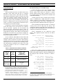
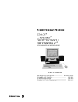
Currently approved (factory installed) plug-in RS-422
board is manufactured by B&B Electronics. Its model
number is 3PXOCC1A (part number 344A3927P38) and it
is an optically-isolated serial board. Subsequent to the
writing of this manual, additional boards may be approved.
Factory-installed plug-in RS-422 boards are configured
correctly before the PC ships from the factory. This
configuration includes setting DIP switches and jumpers on
the plug-in board and disabling the PC's main board serial
COM port per manufacturer's instructions.
Factory configuration for the 3PXOCC1A board
follows. This single-port RS-422 board has one DB-25
connector:
Address Switches (S1)
(MSB)1111101(LSB)
= 3E8 Base Hex Address
422/232 Jumpers*
JP1A − JP1D
RTS/SD Jumper* JP2
422/485 Jumpers*
JP3TX and JP3RX
Interrupt Jumper* JP4
UART Clock Jumper* JP5
“422” positions
(any position)
“422” positions
“IRQ11” position
“*1” position
* See footnote 1 below.
Some early C3 Maestro console for Windows NT PCs
shipped with a substitute B&B Electronics plug-in RS-422
board, model number 3PXCC2A. RS-422 configuration for
this dual-port board with DB-9 connectors is (PORT 1
only):
SERIAL
COM
PORT
RS-232
or
RS-422
SERIAL LINK
USED FOR
INTERFACING
PC COM1
RS-232
Enhanced Audio Enclosure
If COM1: Address
Switches (S1)
(MSB)1111111(LSB)
PC COM2
RS-232
touch-screen data from
touch-screen monitor *
If COM3: Address
Switches (S1)
(MSB)1111101(LSB)
plug-in
RS-422 board
set as COM3
RS-422
**
CEC/IMC
CIM *
* If the console is not equipped with a touch-screen monitor and
RS-232 interfacing to a modem via a DB-9 connector at the PC is
required, PC serial port COM2 may be utilized for interfacing to
the CIM link’s modem at the console. Software COM port setting
changes from the factory default settings are necessary.
** The plug-in RS-422 board may be reconfigured for RS-232
interfacing if RS-232 interfacing to a modem via a DB-25
connector is required. Reconfigurations are accomplished via
jumper position changes on the plug-in RS-232 board. Software
setting changes from the factory default settings are not necessary.
12
In most cases, the PC used in the C3 Maestro console
system is not equipped with a main ("mother") board
RS-422 capable serial COM port. Therefore, a plug-in
RS-422 capable interface board is installed in one of the
PC's internal expansion slots and utilized for CEC/IMC CIM
control data interfacing.
422/485/232 Jumpers
JP1A − JP1C and JP1F
RTS/SD Jumper JP1D
RX Termination
Jumper JP1E
If COM1: Interrupt
Jumper JP3
= 3F8 Base Hex Address
= 3E8 Base Hex Address
“422” positions
(any position)
“Rt OUT” position
“4” position
1 All jumper numbers correspond to 3PXOCC1A boards shipping
mid-1996 (and later). If jumper numbering differs on supplied 3PXOCC1A
board, refer to the appropriate B&B Electronics manual for jumper
identification information.
INTERCONNECTING THE EQUIPMENT
If COM3: Interrupt
Jumper JP3
COM Port
Port Address
Interrupt
COM3
3E8
IRQ11
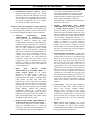
Normally, a pre-wired 100-foot (30.5 meters) cable is
supplied with the console equipment package for RS-422
control data interconnections between the CEC/IMC and a
co-located C3 Maestro console. The cable's part number is
19B804083P3. It has a female DB-25 connector on one end
for mating to the RS-422 male DB-25 connector at the PC
(see the following note). The other end is "pig-tailed" (not
terminated) so the cable's 24-gauge solid wires can be
punched down to the correct terminals at the required
CEC/IMC punch block.
q
Table 6 – Cable 19B804083P3 Color Coding
“11” position
If any other RS-422 plug-in serial board is used the
following board configuration is recommended:
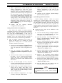
If using the supplied control data cable, mate its female
DB-25 to the PC's RS-422 male DB-25 connector, route
it to the CEC/IMC, shorten the cable as required, and
punch the wires to the correct terminals. See Table 6 or
the cable's assembly diagram (page 21) for wire color
coding. Also see Figure 7A.
AE/LZB 119 1894 R1A
PC
RS-422
CONSOLE
PORT
RS-422
DB-25
SIGNAL
PIN NO.
***
WIRE
COLOR
(Also see
page 21)
TYPICAL
CEC/IMC
CONNECTION
IDENTIFICATION *
1
cable shield
n/a
none **
2
TX-
white/blue
CRT 01 RX- DATA
14
TX+
blue
CRT 01 RX+ DATA
3
RX-
white/orange
CRT 01 TX- DATA
16
RX+
orange
CRT 01 TX+ DATA
7
ground
white/green
none **
*
CEC/IMC Data Concentrator Card identification. See
customer-specific system documentation print-outs for
specific pin/terminal numbers.
** Wire not terminated at CEC/IMC punch block. Insulate
and tie back at punch block.
*** If
PC is equipped with plug-in RS-422 board
3PXCC2A, see Figure 5 for DB-9 connector pin
numbers.
RS-422 TX(WHITE/BLUE)
NOTE
NOTE
If cable 19B804083P3 is utilized and the PC is
equipped with a 3PXCC2A plug-in RS-422 board
(dual ports with DB-9 connectors), a fieldfabricated DB-9-to-DB-25 adapter must be
constructed and utilized as shown in Figure 7C.
In addition, cable 19B804083P3 is not compatible
with earlier plug-in RS-422 boards used with the
C3 Maestro console system. These earlier plug-in
boards are manufactured by ICS and included
model numbers RS422AT-P and RS422I-P. They
can be easily identified by the presence of two LED
indicators visible on the rear plate.
RS-422 RX(WHITE/ORANGE)
SHIELD
SIGNAL GROUND
(WHITE/GREEN)
1
2
14
3
15
16
If cable 19B802083P3 is not used but RS-422 hook-ups
are required, see Figures 4 (or 5) and 7A and/or the
manufacturer's documentation for COM port connector
pin-out details. Fabricate a cable as required and then
use it to interconnect the C3 Maestro's RS-422 control
data COM port to the appropriate CEC/IMC Data
Concentrator Card as required. Shielded cabling is
recommended. Per RS-422 specifications, cable length
should be limited to 4000 feet (1219 meters) or less.
17
(ORANGE)
(BLUE)
6
5
RS-422 RX+
RS-422 TX+
q
4
18
7
19
8
20
9
21
10
22
11
23
12
24
13
25
NOTES:
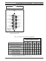
1. VIEWED FROM BACK OF COMPUTER (MALE DB-25) OR
WIRING SIDE OF MATING CONNECTOR (FEMALE
DB-25).
2. TX LINES MUST CONNECT TO "CRT" RX LINES AT
CEC/IMC CONCENTRATOR CARD OR PUNCH BLOCK, +
TO + AND - TO -.
RX LINES MUST CONNECT TO "CRT" TX LINES AT
CEC/IMC CONCENTRATOR CARD OR PUNCH BLOCK, +
TO + AND - TO -.
3. COLOR CODING INDICATES CABLE 19B804083P3 WIRE
COLORS.
Figure 4 – Plug-In RS-422 Board DB-25 Connector
Pin-Out (B&B Electronics 3PXOCC1A Board)
NOTE
NOTE
Do not over-tighten the screws on the DB-style
connectors.
13
AE/LZB 119 1894 R1A
INTERCONNECTING THE EQUIPMENT
ZyXEL Modem Configuration
RS-422 TX+
(BLUE)
RS-422 TXRS-422 RX-
(WHITE/BLUE)
(WHITE/ORANGE)
SIGNAL GROUND
(WHITE/GREEN)
1
2
6
3
7
4
8
CONNECTOR ON PLUG-IN
(EXPANSION) RS-422
BOARD 3PXCC2A; NOT ON
PC MAIN/SYSTEM BOARD!
5
9
RS-422 RX+
(ORANGE)
NOTES:
1. VIEWED FROM BACK OF COMPUTER (MALE DB-9) OR
WIRING SIDE OF MATING CONNECTOR (FEMALE DB-9).
2. TX LINES MUST CONNECT TO "CRT" RX LINES AT
CEC/IMC CONCENTRATOR CARD OR PUNCH BLOCK, +
TO + AND - TO -.
RX LINES MUST CONNECT TO "CRT" TX LINES AT
CEC/IMC CONCENTRATOR CARD OR PUNCH BLOCK, +
TO + AND - TO -.
3. COLOR CODING INDICATES CABLE 19B804083P3 WIRE
COLORS. NOTE REQUIREMENT FOR FIELD-FABRICATED
DB-9-TO-DB-25 ADAPTER IF USING THIS CABLE.
Figure 5 – Plug-In RS-422 Board DB-9 Connector
Pin-Out (B&B Electronics 3PXCC2A Board)
The following procedure provides basic programming
instructions for ZyXEL™ U-1496 series modems when
employed in a C3 Maestro console-to-CIM dedicated 4-wire
line control data link. These modems are available in desktop and rack-mount versions. ZyXEL modems (and related
accessories) are stocked under part numbers 19A149786P6
thru P14. They feature front panel programming via a simple
keyboard, an LCD and several LED status indicators;
therefore the use of an external terminal or terminal
emulation software running on a PC is not required. Unless
otherwise noted in bold print, both modems in a modem
pair are programmed identically:
1.
If necessary, using the modem’s RESET submenu,
reset the modem to the factory default configuration.
Refer to ZyXEL modem user’s manual for specific
instructions.
2.
Access the modem’s TERMINAL OPTIONS submenu
and set each of the following options to the required
setting:
RS-232 Interfacing (Remote Console Hook-Ups Via
4-Wire Modems And RS-232 Interconnections)
When the C3 Maestro is installed at a remote location
from the CEC/IMC, a serial control data link must be
established via RS-232 connections and 4-wire full-duplex
9600 baud data modems. Since the C3 Maestro requires a
dedicated or continuous serial link (non-dial-up), a 4-wire
leased line (or equivalent) meeting 3002 data grade
specifications must be employed between the CEC/IMC and
the C3 Maestro in a remote console installation.
Figure 7B shows typical control data interconnections
for a remote console installation using RS-232 connections
and full-duplex 4-wire modems. At the CEC/IMC Data
Concentrator Card, RS-232 connections are made at J13, not
J12. Observe all notes listed in the figure if wiring an
installation of this type. Recommended modem settings are
listed in the following sections.
If using the factory-supplied 3PXOCC1A board for PCto-modem link interfacing, the RS-422/232-related jumpers
on the board must be reconfigured from the factory default
positions to the positions as follows:
422/232 Jumpers*
JP1A − JP1D
RTS/SD Jumper* JP2
“232” positions
“RTS” position
OPTION
REQUIRED SETTING
DATA FORMAT
ASYNC
CHARACTER LENGTH
10
COMMAND SET
AT
DTE RATE OPTIONS
FIXED AT DTE RATE
DTR OPTIONS
108.2 + RST
DCD OPTIONS
TRACKS CARRIER
RTS OPTIONS
IGNORED
DSR OPTIONS
DATA SET READY
COMMAND ECHO
DISABLED
RESULT CODE
DISABLED
DTE ASYNC SPEED
9600
3.
Access the modem’s MODEM OPTIONS submenu
and set each of the following options to the required
setting:
OPTION
REQUIRED SETTING
* See footnote on page 12.
If the PC is equipped with a 3PXCC2A board, the
RS-422/232-related jumpers on the board must be
reconfigured from the factory default positions to the
positions as follows:
422/485/232 Jumpers
JP1A and JP1F
14
“232” positions
LINK OPTIONS
V.32 9600T
QUALITY ACTION
AUTO RETRAIN
DEFAULT DIAL
PH0
DIAL BACKUP
DISABLED
GUARD TONE
NONE
INTERCONNECTING THE EQUIPMENT
OPTION
REQUIRED SETTING
RDL REQUEST
DENY
LLINE TX POWER
0 DBM (or as required;
use -15 DBM if line loss
is 0 Dbm)
PHONE JACK
SINGLE RJ11
MAKE/BREAK RATIO
39% / 61%
SECONDARY CHANNEL
DISABLED
PANEL LOCK
UNLOCK (or as required)
SYNC CLOCK
MASTER = CEC/IMC
modem; SLAVE =
console modem
AUTO HANDSHAKE
ORIGINATE = CEC/
IMC modem;
ANSWER = console
modem
LINE TYPE
4.
AE/LZB 119 1894 R1A
8.
Using the modem’s RESET submenu, set RESET =
PROFILE 0. This causes the modem to initialize with
the PROFILE 0 configuration established in the
previous steps whenever it is powered-up, or reset via a
DTR signal from the PC.
9.
Repeat the above configuration for the second modem
in the modem pair.
Refer to Figure 7A and 7B as necessary and/or the
modem manufacturer’s documentation for cable hook-up
and wiring information.
Other Modems
•
Modem Options
DCE Rate = 9600
Originate/Answer = Originate (CEC/IMC modem)
Originate/Answer = Answer (C3 Maestro modem)
V.32 Fast Train = Enabled
Auto Retrain = Enabled
4LL
Internal/External Clock = Internal
Dial-Up/Leased Line = Leased
Access the modem’s ERROR CONTROL submenu
and set each of the following options to the required
setting:
2-Wire/4-Wire = 4 Wire
TX Level = (as required; use -15 dBm if line loss is 0 dB)
OPTION
REQUIRED SETTING
Dial Backup = Manual
CONTROL LEVEL
V.42
Loop Back Time = 15 minutes
FLOW CONTROL
DISABLED
Dial Line = RJ11
NEGOTIA FALLBACK
STAYS ON-LINE
Line Current Disconnect = Long
BREAK HANDLING
DESTRUCTIVE
Long Space Disconnect = Enabled
5.
Access the modem’s AUDIO OPTIONS submenu and
set each of the following options to the required setting:
OPTION
V.22 Guard Tone = Disabled
•
MNP Protocol = Enabled
REQUIRED SETTING
SPEAKER CONTROL
ON UNTIL CONNECTED
SPEAKER VOLUME
7 (or as required)
RING VOLUME
7 (or as required)
6.
Maintain all modem S registers per default settings
except set S2 = FF and set S35 = 00.
7.
Using the modem’s SAVE TO submenu, save this
modem configuration as PROFILE 0. If necessary,
refer to ZyXEL modem user’s manual for specific
instructions.
MNP Options
Auto Fallback = Enabled (or Normal)
Flow Control = CTS Only
XON/XOFF Pass Through = Enabled
Data Compression = Disabled
Inactivity Timer = Off
Break Control = 5
•
DTE Options
Synchronous/Asynchronous Data = Asynchronous
DTE Rate = 9600
Character Length = 8 Bits
15
AE/LZB 119 1894 R1A
INTERCONNECTING THE EQUIPMENT
Parity = None
Commanded Dialer = Asynchronous
AT Command Set = Disabled
DTR Control = Disabled
DSR = Forced High
DCD = Normal
CTS = Forced High
DTE Fallback = Disabled
Options = Retained At Disconnect
•
•
•
Test Options - All Disabled (or factory defaults)
Dial Line Options - (not applicable; leave at factory
defaults)
Speaker Options
At the C3 Maestro, audio connections terminate at the
DB-25 connector on the Enhanced Audio Enclosure's rear
panel. This connector is labeled "LINES 1-4". Its pin-out is
shown in Figures 6 and 7A and Table 11. It has female
contacts; therefore, the required mating connector is a male
DB-25.
Normally, a pre-wired 100-foot (30.5 meters) cable is
supplied with the console equipment package for audio
interconnections between the Enhanced Audio Enclosure
and the CEC/IMC. This 8-pair shielded cable's part number
is 19B804083P2. It has a male DB-25 connector on one end
for mating to the Enhanced Audio Enclosure's "LINES 1-4"
female DB-25 connector. The other end is "pig-tailed" (not
terminated) so the cable's 24-guage solid wires can be
punched down to the correct terminals at the required
CEC/IMC's punch block.
q
Volume Control = Low
Control = On Until Carrier Detect
Audio Links
Audio Concentrator Cards at the back of the CEC/IMC
cabinet provide audio connections at the CEC/IMC. Like the
control data connections, audio connections are normally
extended out of the CEC/IMC cabinet via Telco cable(s) and
line terminations are actually made at punch blocks. See
Figure 7A. See the customer-specific system documentation
print-outs for Concentrator Card connector pin-out details.
Table 7 shows line requirements between the
C3 Maestro and the CEC/IMC for each audio input or
output 2-wire 600-ohm twisted pair. Note that two (2)
Enhanced Audio Enclosure output pairs, Line 2 out and Line
3 out are never used. These audio output lines are provided
for future expansion use.
16
q
If cable 19B804083P2 is used, mate its DB-25 to the
Enhanced Audio Enclosure, route it to the CEC/IMC,
shorten it as required, and punch the wires to the correct
punch block's terminals. Wire color coding is indicated
in Figure 6 and in the cable's assembly diagram (page
22). Refer to the CEC/IMC customer-specific system
documentation print-outs for CEC/IMC Audio
Concentrator Card pin-outs which map over to the
punch blocks via Telco cables.
If cable 19B804083P2 is not used, fabricate an
equivalent cable, less unnecessary pairs, to interconnect
the required pairs between the Enhanced Audio
Enclosure's "LINES 1-4" DB-25 connector and the
appropriate CEC/IMC Audio Concentrator Card's pins
or CEC/IMC punch block's terminals. Shielded cabling
is recommended. See Figures 6 and 7 and Tables 7 and
11 for details.
INTERCONNECTING THE EQUIPMENT
AE/LZB 119 1894 R1A
NOTE
NOTE
Do not over-tighten the screws on the DB-style
connectors.
LINES
1-4
LINE 1 IN HI/+
1
(WHITE/BLUE)
14
LINE 1 IN LO/(BLUE)
LINE 1 OUT HI/+
(WHITE/GRAY)
2
15
LINE 1 OUT LO/(GRAY)
3
16
LINE 2 IN HI/+
4
(WHITE/ORANGE)
17
LINE 2 IN LO/-
LINE 2 OUT HI/+
(RED/BLUE)
5
(ORANGE)
18
LINE 2 OUT LO/(BLUE/RED)
6
19
LINE 3 IN HI/+
7
(WHITE/GREEN)
20
LINE 3 IN LO/-
LINE 3 OUT HI/+
(RED/ORANGE)
8
(GREEN)
21
LINE 3 OUT LO/(ORANGE/RED)
9
22
LINE 4 IN HI/+
10
(WHITE/BROWN)
23
LINE 4 IN LO/(BROWN)
24
LINE 4 OUT LO/(GREEN/RED)
12
NOTES:
1. VIEWED FROM BACK OF ENHANCED
AUDIO ENCLOSURE (FEMALE DB-25)
OR WIRING SIDE OF MATING
CONNECTOR (MALE DB-25).
2. UNLABELED PINS ARE NO
CONNECTIONS (N.C.)
3. COLOR CODING INDICATES CABLE
19B804083P2 WIRE COLORS
LINE 4 OUT HI/+
(RED/GREEN)
11
25
13
Figure 6 − Audio Line Input And Output Connections
At Enhanced Audio Enclosure
Table 7 − C3 Maestro-To-CEC/IMC Audio Line Requirements
ENHANCED AUDIO ENCLOSURE AND
CEC/IMC IDENTIFICATION (4-Wire)
LINE 1
LINE 2
LINE 3
LINE 4
CONSOLE INPUT OR OUTPUT (2-Wire)
IN
OUT
IN
OUT
IN
OUT
IN
OUT
CEC/IMC INPUT OR OUTPUT (2-Wire)
OUT
IN
OUT
IN
OUT
IN
OUT
IN
SELECT SPEAKER/HEADSET
ü
MICROPHONE
UNSELECT SPEAKER 1
ü
X
UNSELECT SPEAKER 2
ü
X
*
X
UNSELECT SPEAKER 3 *
X
CALL DIRECTOR PATCH *
X
X
= 2-wire connection always required
= 2-wire connection required if console is so equipped
= Unselect speaker 3 not available if console is interconnected to a Call Director
17
AE/LZB 119 1894 R1A
INTERCONNECTING THE EQUIPMENT
Figure 7A − CEC/IMC-To-C3 Maestro Interconnections (Co-Located)
18
INTERCONNECTING THE EQUIPMENT
AE/LZB 119 1894 R1A
Figure 7B − CEC/IMC-To-C3 Maestro Interconnections (Remote And/Or RS-232)
19
AE/LZB 119 1894 R1A
INTERCONNECTING THE EQUIPMENT
Figure 7C − Field-Fabricated Adapter
20
INTERCONNECTING THE EQUIPMENT
AE/LZB 119 1894 R1A
CABLE ASSEMBLY DIAGRAM
CONTROL DATA CABLE (100-FOOT)
19B804083P3
(Made from 19B804083 Sh. 4, Rev. 3)
21
AE/LZB 119 1894 R1A
INTERCONNECTING THE EQUIPMENT
CABLE ASSEMBLY DIAGRAM
AUDIO CABLE (100-FOOT)
19B804083P2
(Made from 19B804083 Sh. 3, Rev. 3)
22
INTERCONNECTING THE EQUIPMENT
PERSONAL COMPUTER
PC-To-Enhanced Audio Enclosure Serial Data
Interconnect Cable
The PC-to-Enhanced Audio Enclosure RS-232 serial
data link uses cable P29/5010150000 (350A1371P29). This
cable has a female DB-9 connector on one end for mating to
the PC's male DB-9 serial COM port connector. The cable's
other end has a male DB-9 connector for mating to the
female DB-9 connector labeled "PC" at the Enhanced
Audio Enclosure. The cable is nine (9) feet long. It should
not be modified in any way and "extension" cables are not
recommended for this 9600 baud serial link. Identical cables
are also used between the Enhanced Audio Enclosure and
the Speaker Assemblies.
q
Mate the cable's female DB-9 connector to the PC's
male DB-9 serial COM port connector used for
Enhanced Audio Enclosure interfacing. Normally, the
COM1 port is used. Mate the other end of the cable to
the Enhanced Audio Enclosure's DB-9 connector
labeled "PC". This interconnection is shown in Figure 1
but not in Figure 7.
Standard PC Keyboard
During dispatch operations, the standard PC keyboard is
not utilized. However during the console set-up process,
access to this keyboard will be required:
•
for user account name and/or password entry at PC
boot-up if Windows NT manual log-on is enabled;
•
for Windows NT administrative-type changes, if
required;
•
to configure other Windows NT settings, if
required;
•
to configure the console application via the
Configuration Editor and/or UDS Configurator
programs, if required; and,
•
q
to start the console's application program if no
mouse/track-ball is available and manual console
application start-up at Windows NT log-on is the
current configuration.
Connect the standard PC keyboard to the PC in
accordance with the manufacturer's instructions. The
plug on the keyboard's cable mates with a connector on
the back of the PC.
Mouse (Or Other Pointing Device)
Normally, the C3 Maestro console for Windows NT
ships from factory with a standard 2-button mouse. Another
AE/LZB 119 1894 R1A
type of pointing device such as a track-ball may be
substituted provided it meets compatibility requirements.
q
Connect the pointing device to the PC as recommended
by the manufacturer. The mating connector is on the
back of the PC.
Video Display Monitor
q
q
Interconnect the video display monitor's video cable to
the Personal Computer in accordance with the PC
and/or monitor manufacturer's instructions.
If the monitor is a touch-screen unit, there is a second
cable between it and the PC which transmits touch information to the PC. In this case, also connect this second cable per the PC’s and/or monitor manufacturer's
instructions. As shown in Table 5, COM2 at the PC is
normally utilized for touch-screen data interfacing.
However, some consoles were equipped with PC expansion bus touch-screen interface cards.
ENHANCED AUDIO ENCLOSURE
All Enhanced Audio Enclosure interconnections are
made at the rear panel of the enclosure. Secure the cables
with cable ties as necessary.
Dispatch Keyboard (if used)
The Dispatch Keyboard interfaces to the console system
via the Enhanced Audio Enclosure. This keyboard's part
number is P29/7590182003 (350A1371P17). It is
sometimes referred to as the "custom keyboard".
q
Connect the Dispatch Keyboard to the Enhanced Audio
Enclosure by plugging its male DB-9 connector to the
female DB-9 connector on Enhanced Audio Enclosure's
rear panel. On the rear panel, this connector is labeled
"KBD". Its pin-out is indicated in Table 23.
NOTE
NOTE
Do not over-tighten the screws on the DB-style
connectors.
Desk Mic (if used)
q
Connect the desk microphone (option CRMC3D or
equivalent) to the Enhanced Audio Enclosure by mating
its male DB-9 connector to the female DB-9 connector
labeled "DESK MIC" on the Enhanced Audio
Enclosure's rear panel. The desk mic's cable is five (5)
feet (1.52 meters) long. The DB-9's pin-out is shown in
Table 14. Observe the microphone priority NOTE in
the following section (page 24); the desk mic has the
lowest priority.
23
AE/LZB 119 1894 R1A
INTERCONNECTING THE EQUIPMENT
CAUTION
Headset Jacks (if used)
q
q
CAUTION
At the selected location, secure each headset jack box
(part of option CRCN1W or equivalent) to the mounting
surface using the four (4) #10 thread-forming screws
supplied in the installation kit or use alternate hardware
if required (not supplied). Before mounting, verify
adequate clearance is maintained for the headset's plugs.
If using both jack boxes, label them "SUPERVISOR"
and "OPERATOR" as required (per cable
interconnections accomplished in the following
paragraph).
Connect each headset jack box to the Enhanced Audio
Enclosure using the 6-foot (1.83 meters) cable supplied.
This cable (part number 19C337102P1 supplied with
CRCN1W) has male DB-9 connectors on both ends.
One end mates with the female DB-9 connector at a
jack box and the other end mates to the female DB-9
connector at the Enhanced Audio Enclosure's rear
panel. The connectors on the rear panel are labeled
"SUPER H/S" and "OPER H/S" for the supervisor
and operator headsets respectively. Interconnect the
cables accordingly. The DB-9 connectors' pin-outs are
indicated in Tables 15 and 16.
DO NOT connect a boom or gooseneck
microphone to one of the other female DB-9
microphone connectors at the rear panel of the
Enhanced Audio Enclosure. Damage to the mic's
magnetic voice coil may occur.
Table 8 − Boom/Gooseneck Mic Wiring*
WIRE COLOR
DB-9 PIN NUMBER
Black
9
White
5
Shield
1
* Also see the following NOTE.
NOTE
NOTE
All boom and gooseneck mic connectors (male DB9) must have pins 2 and 3 jumpered together so the
sense circuit will be active when the mic is
connected to the Enhanced Audio Enclosure.
NOTE
NOTE
Operator microphone priority is (highest to lowest):
•
Operator Headset Mic
•
Boom/Gooseneck Mic
(highest)
â
• Desk Mic (lowest)
(lowest)
The boom/gooseneck mic has priority over the desk
mic when no headset is connected. Desk mic audio
and PTTs are ignored if a headset or
boom/gooseneck mic is connected.
Boom/Gooseneck Mic (if used)
Footswitches (if used)
Two (2) female DB-9 connectors are located on the rear
panel of the Enhanced Audio Enclosure for footswitch
interconnections. Footswitches used with the C3 Maestro
dispatch console include single-footswitch option CRSU3B
and dual-footswitch option CRSU3C. On the dualfootswitch, one switch (PTT) keys the mic and the other
switch is a monitor switch. A single-footswitch provides
only a PTT function. See Tables 19 and 20 for specific
connector pin-out details. Footswitch operation is as
follows:
•
A boom microphone (option CRMC3E or equivalent)
or a gooseneck microphone (option CRMC3F or equivalent)
may be connected to the Enhanced Audio Enclosure as
follows:
q
24
Mount the microphone in accordance with the
instructions supplied with the mic. With the gooseneck
microphone, the supplied male DB-9 connector must be
soldered to the cable's wires in accordance with Table 8
after the mic's cable is routed through the mounting
surface. Connect the boom/gooseneck male DB-9
connector to the female DB-9 connector labeled "B/G
MIC" on Enhanced Audio Enclosure's rear panel. Cable
length is four (4) feet (1.22 meters). Table 13 indicates
the "B/G MIC" connector's pin-out.
•
•
Depressing the PTT switch on a footswitch
connected to the "OPER FT. SW." DB-9
connector will activate the operator's headset mic if
the headset is connected. If the headset is not
connected, the boom or gooseneck mic will become
active when this footswitch PTT switch is
depressed and/or the desk microphone is PTTed.
Depressing the PTT switch on a footswitch
connected to the "SUPER FT. SW." DB-9
connector will activate the supervisor's headset mic
if the headset is connected.
If a dual footswitch is connected to either the
"OPER FT. SW." or "SUPER FT. SW." DB-9
connectors, depressing its monitor switch will
INTERCONNECTING THE EQUIPMENT
q
activate the console's conventional channel monitor
function.
All footswitch cables terminate with male DB-9
connectors. Mate the appropriate male DB-9 footswitch
connector to the respective female DB-9 connector at
the Enhanced Audio Enclosure's rear panel. Tables 19
and 20 indicate "OPER FT. SW." and "SUPER FT.
SW." connector pin-outs.
labeled "RECORDER" on the Enhanced Audio Enclosure's
rear panel.
q
Speakers (if used)
Desktop and rack-mount Speaker Assemblies used with
the Enhanced Audio Enclosure each basically consist of
mechanical hardware, one or more speakers, audio
amplification circuitry, and a volume control potentiometer.
The mechanical hardware may be of several different
varieties providing either desktop speaker operation in the
form of a self-contained single-speaker case or a rack-mount
version in the form of a standard 19-inch EIA rack mount
assembly. The 2-speaker rack-mount versions are generally
assembled with one amplified speaker in the far left-hand
position (select speaker), one amplified speaker in the far
right-hand position (unselect speaker) and blank panels
installed in the two center positions. Four-speaker consoles
are generally equipped with two separate 2-speaker rack
mount assemblies.
q
Install or mount each Speaker Assembly in a suitable
location and then interconnect it to the Enhanced Audio
Enclosure
using
cable
P29/5010150000
(350A1371P29). This cable is 9 feet (2.74 meters) in
length. It is identical to the cable that interconnects the
PC's serial COM port to the Enhanced Audio Enclosure.
Mate the cable's female DB-9 connector to the
appropriate male DB-9 connector on the Enhanced
Audio Enclosure's rear panel. These male connectors
are labeled "SEL SPKR" (select speaker), "UNSEL
SPKR1" (first unselect speaker), "UNSEL SPKR2"
(second unselect speaker) and "UNSEL SPKR3" (third
unselect speaker). Connect the other end of the cable to
the female DB-9 connector at the respective Speaker
Assembly. If necessary, see Tables 17 and 18 for DB-9
pin-outs.
NOTE
NOTE
Load resistors are not required for unused
Enhanced Audio Enclosure speaker outputs.
Recorder Outputs (if used)
To provide call-check recorder support, select and
unselect audio outputs are available from the Enhanced
Audio Enclosure. These unbalanced 600-ohm outputs
appear at the removable screw-terminal type terminal block
AE/LZB 119 1894 R1A
Interconnect the outputs to call-check recorders as
required. These outputs are not isolated from ground
through isolation transformers and the two ground
terminals are common. See Figure 8 and Table 26 for
terminal identification. See the specifications in manual
AE/LZB 119 1892 for audio signal output level
specifications. If required, audio output levels may be
adjusted via menu selection within the console’s
Dispatch Manager program.
WIRE SECURING SCREWS
LOCATED ON TOP
WIRE ATTACHMENT:
1. UNPLUG TERMINAL BLOCK FROM
MATING CONNECTOR.
2. IF REQUIRED, COMPLETELY
LOOSEN WIRE SECURING SCREW.
3. INSERT WIRE.
4. TIGHTEN WIRE SECURING SCREW.
5. REPEAT FOR OTHER WIRES.
6. RECONNECT TERMINAL BLOCK TO
"RECORDER" MATING CONNECTOR.
RECORDER
1
4
UNSELECT/
TELEPHONE OUT
GROUND
SELECT OUT
GROUND
Figure 8 – Recorder Outputs At
Enhanced Audio Enclosure
External Paging Encoder Input (if used)
Connections for an external paging tone encoder are
located on a second removable screw-terminal terminal
block on Enhanced Audio Enclosure's rear panel. A
600-ohm balanced line audio input and a PTT (page enable)
input are included. As shown in Figure 9, this terminal block
is labeled "PAGING".
Pager balanced audio on terminals 1 and 2 is switched
in when the PTT line at terminal 3 becomes active by
grounding it to terminal 4. Typically, the PTT action is
accomplished by a relay in the pager. During a page, no
other audio signals are applied to the Line 1 output. Also,
the paging signal is sent to the headsets and speakers
approximately 16 dB lower than other audio signal levels.
q
Connect the pager to the terminal block in accordance
with the manufacturer's instructions, Figure 9 and Table
25. The audio terminals are isolated from ground. See
the specifications page for audio signal input level
specifications. If required, audio input level adjustment
can be accomplished by changing the respective digital
pot’s setting using the Dispatch Manager’s Digital Pot
Adjustment dialog box; see the procedure on page 7 of
this manual for additional details.
25
AE/LZB 119 1894 R1A
INTERCONNECTING THE EQUIPMENT
PAGING
WIRE SECURING SCREWS
LOCATED ON TOP
WIRE ATTACHMENT:
1. UNPLUG TERMINAL BLOCK FROM
MATING CONNECTOR.
2. IF REQUIRED, COMPLETELY
LOOSEN WIRE SECURING SCREW.
3. INSERT WIRE.
4. TIGHTEN WIRE SECURING SCREW.
5. REPEAT FOR OTHER WIRES.
6. RECONNECT TERMINAL BLOCK TO
"PAGING" MATING CONNECTOR.
1
WIRE SECURING SCREWS
LOCATED ON TOP
RELAYS
1
18
4
PAGER AUDIO
INPUT +
PAGER AUDIO
INPUT PAGER PTT INPUT
GROUND
Figure 9 – Pager Inputs At Enhanced Audio Enclosure
RELAY OUTPUT
TERMINAL 1
RELAY OUTPUT
TERMINAL 18
WIRE ATTACHMENT:
1. UNPLUG TERMINAL BLOCK FROM MATING CONNECTOR.
2. IF REQUIRED, COMPLETELY LOOSEN WIRE SECURING SCREW.
3. INSERT WIRE.
4. TIGHTEN WIRE SECURING SCREW.
5. REPEAT FOR OTHER WIRES.
6. RECONNECT TERMINAL BLOCK TO "RELAYS" MATING CONNECTOR.
(See Table 24 for terminal identifications)
Figure 10 – Relay Terminal Block At
Enhanced Audio Enclosure
Relay Outputs (if used)
Call Director (if equipped)
Form-C relay contacts (single-pole double-throw) are
available from the Enhanced Audio Enclosure for external
device control. Contact connections are made at the screwterminal type terminal block on the rear panel labeled
"RELAYS". Even though these relays are also controlled
from the console’s dispatch keyboard, they are not the same
as and they should not be confused with the relays within the
CEC/IMC utilized for auxiliary I/O interfacing.
As shown in Figure 1, all C3 Maestro-to-Call Director
interconnections at the console are made at the Enhanced
Audio Enclosure's connector labeled "CALL DIR". A Call
Director telephone patch also requires an additional 4-wire
balanced line between the Enhanced Audio Enclosure and
the console’s CIM Audio Board within the CEC/IMC. At
the CEC/IMC, CIM audio channel/line four (4) is used for
Call Director interfacing. CD control data interfacing is
handled over the existing RS-232/RS-422 serial control data
interface between the PC and the CEC/IMC. Therefore, no
additional control data link must be added to support Call
Director patch equipment. Refer to Figures 1, 6, 7 and 11 for
interconnection details and the following discussion on
CEC/IMC line audio line requirements.
As shown in Table 24, the first relay (relay 1) is
activated when the console is keyed (PTTed). During the
key, the relay's common and normally-open contacts close
and its common and normally-closed contacts open. The
second relay's (relay 2) common and normally-open contacts
close while <Alt><F10> is depressed at the Dispatch
Keyboard. Like the first relay, this relay's action is
considered "momentarily" as it is only in the active state
when the <Alt><F10> keys are depressed. The third relay's
(relay 3) contacts toggle open/close at an <Alt><F9>
keystroke from the Dispatch Keyboard. The other relays are
not supported by software.
q
26
As required, connect the relay contact outputs to
external equipment. See Table 24 and Figure 10.
Specified contact rating for all relays is 0.75 amps at 26
Vdc. Open contact isolation is specified to 500 Vrms at
60 Hz. Isolation between any relay terminal and the
Enhanced Audio Enclosure's ground is also specified to
500 Vrms at 60 Hz.
Console-to-CEC/IMC Audio Interconnections
All CEC/IMC line audio in to and out of a C3 Maestro
dispatch console system enters and leaves via the DB-25
connector labeled "LINES 1 - 4" on the Enhanced Audio
Enclosure's rear panel. If the console is connected to a Call
Director, Line 4 between the Enhanced Audio Enclosure and
the CEC/IMC must be established for CD audio routing
between the console and the CEC/IMC. In this case, the
third unselect speaker audio is not available.
Table 9 describes the audio signals between the
Enhanced Audio Enclosure and the CIM within the
CEC/IMC. The descriptions are relative to the Enhanced
Audio Enclosure. All signals on these 600-ohm pairs have
typical levels between -5 dBm to 0 dBm.
INTERCONNECTING THE EQUIPMENT
AE/LZB 119 1894 R1A
Table 9 − Enhanced Audio Enclosure-To-CEC/IMC Call Director Audio Signal Descriptions
TYPE
INPUT /
OUTPUT
Patched Radio
Input
Radio audio from CIM TX channel/line 4. During a CD telephone patch, this audio is heard
at the telephone.
CD/Operator Mic
Output
Telephone/operator mic audio to CIM RX channel/line 4. This audio is heard at the radio.
USE
Table 10 − Enhanced Audio Enclosure-To-Call Director Control & Audio Signal Descriptions
INPUT /
OUTPUT
USE
ON-HOOK N.O.
(pin 1) and
ON-HOOK COMMON
(pin 6)
Output
Optional – Normally-open relay contact (Form-A). Closure generated when the
console disconnects the CD from the CEC/IMC. Used to put CD on-hook, if an input
exists. The relay remains energized for approximately 1.2 seconds. This value is
fixed in the firmware and cannot be changed. Relay contact rating:
0.75 A @ 26 Vdc, 500 Vrms isolation from ground @ 60 Hz
CD HOOK SENSE IN
(pin 2) *
Input
Active low when the CD is placed off-hook. Typically connects to a dry contact
(SPST switch, Form-A relay, etc.) from Call Director.
CD JACK SENSE IN
(pin 3) *
Input
Optional – Active low when a handset is plugged into the CD. This handset overrides
all audio connections to the Enhanced Audio Enclosure. The operator talks directly
to the phone via the handset instead of using the console’s headset or mic/speaker.
Typically connects to a dry contact from Call Director.
GROUND (pin 4) *
n/a
Signal ground for CD HOOK SENSE IN and CD JACK SENSE IN sense inputs.
CD IN
(pins 5 and 9)
Input
Audio from the CD (telephone mic). This audio is heard by a radio in patch
operation, or by operator headset in normal operation. 600-ohm balanced input:
-26 dBm to -14 dBm, typically -20 dBm.
Output
Radio/operator mic audio to the CD (telephone receiver). This audio is heard by the
telephone. 600-ohm balanced output:
-11 dBm to +1 dBm, typically -5 dBm.
NAME
CD OUT
( pins 7 and 8)
* GROUND (pin 4) is common for CD HOOK SENSE IN (pin 2) and CD JACK SENSE IN (pin 3)
This ground is not isolated from chassis ground.
CALL
DIR
1
6
CD HOOK SENSE IN
2
CD JACK SENSE IN
3
ON-HOOK N.O.
ON-HOOK COMMON
7
8
GROUND
HI/+
LO/-
CD OUT
HI/+
LO/-
CD IN
4
9
5
NOTE:
1. VIEWED FROM BACK OF ENHANCED
AUDIO ENCLOSURE OR WIRING SIDE
OF MATING CONNECTOR.
Figure 11 − Call Director Interface Connector At Enhanced Audio Enclosure
27
AE/LZB 119 1894 R1A ENHANCED AUDIO ENCLOSURE PIN-OUTS
q
If not accomplished in the previous instructions in this
manual, install a 4-wire balanced line (two pairs)
between the required CEC/IMC Audio Concentrator
Card and Enhanced Audio Enclosure. Refer to the
section entitled “CEC/IMC INTERCONNECTIONS”
(page 11). In most cases, the pre-wired 100-foot audio
cable (part number 19B804083P2) is utilized as
described in the “Audio Links” subsection (page 16).
ENHANCED AUDIO ENCLOSURE
PIN-OUTS
Tables 11 thru 27 list the pin-outs of the connectors on
the Enhanced Audio Enclosure's rear panel. "NAME"
designations in the tables correspond to the labeling used on
the I/O Backplane Board schematic diagram. Figure 12
shows the rear panel and serves as a guide to the table(s).
Table 11 – CEC/IMC Audio Lines
(female DB-25 labeled "LINES 1-4")
Console-to-Call Director Interconnections
Table 10 describes the various signals between the
Enhanced Audio Enclosure and the Call Director. The
descriptions are relative to the Enhanced Audio Enclosure.
All Enhanced Audio Enclosure connections are made at the
"CALL DIR" female DB-9 connector. Figure 11 and Table
12 indicate the connector's pin-out.
q
Interconnect the Enhanced Audio Enclosure to the Call
Director as required per Tables 10 and 12, Figure 11,
and the Call Director's documentation.
EQUIPMENT ROOM GROUNDING
Proper grounding techniques should be observed in
order to protect the equipment and service personnel from
lightning and other sources of electrical surges. All consoles
should be connected to properly grounded 3-terminal
outlets. If used, lightning arrestors, UPS equipment, and all
other console-associated equipment should also be properly
grounded. If necessary, refer to LBI-39067 for detailed
grounding procedures.
ELECTROSTATIC DISCHARGE (ESD)
PROTECTION
Always observe proper equipment handling procedures
to protect the equipment from ESD damage. Refer to
LBI-38737 for complete details.
AC POWER AND UPS EQUIPMENT
All consoles require 115 or 230 Vac (47 to 63 Hz)
power sources. As a minimum, each outlet should be circuitbreaker protected per local building codes.
UPS protection is optional. Maximum required UPS
wattage rating for a single console system should be based
on the required maximum sums of the Enhanced Audio
Enclosure (200 watts max.), the PC's computer (per
manufacturer's specifications) and the PC's video display
monitor (per manufacturer's specifications).
PIN
NAME
USE *
1
LINE_1_IN+
2
LINE_1_IN-
Line 1
balanced input
3
no connection
4
LINE_2_IN+
5
LINE_2_IN-
6
no connection
7
LINE_3_IN+
8
LINE_3_IN-
9
no connection
10
LINE_4_IN+
11
LINE_4_IN-
12
no connection
13
no connection
14
LINE_1_OUT+
15
LINE_1_OUT-
16
no connection
17
LINE_2_OUT+
18
LINE_2_OUT-
19
no connection
20
LINE_3_OUT+
21
LINE_3_OUT-
22
no connection
23
LINE_4_OUT+
24
LINE_4_OUT-
25
no connection
Line 2
balanced input
Line 3
balanced input
Line 4
balanced input
Line 1
balanced output
Line 2
balanced output
Line 3
balanced output
Line 4
balanced output
* With respect to the Enhanced Audio Enclosure. For
example, pins 1 and 2 are Enhanced Audio Enclosure line
inputs; audio signals on these inputs originate from the
CEC's/IMC's CIM line outputs. Also see Figure 6.
28
KBD
PC
I/O
SUPER
OPER
J18
F
J16
F
J15
F
J14
F
See Table 13
F
See Table 12
F
M
J11
J7
F
J6
F
See Table 14
See Table 11
AUX. IN
4
J2
1
4
J13
PAGING
OFF
1
RECORDER
J1
See Table 15
J5
F
OPER
H/S
DESK
MIC
See Table 16
J4
F
See Table 17
J3
M
J10
See Table 19
M
J9
See Table 20
M
J8
FT. SW.
J17
F
18
J20
CD/
UNSEL
SPKR3
See Table 21
See Table 18
B/G
MIC
See Table 26
See Table 22
See Table 18
CALL
DIR
LINES
1-4
See Table 25
See Table 23
See Table 18
SUPER
H/S
(TOP)
SEL
SPKR
UNSEL
SPKR1
UNSEL
SPKR2
RELAYS
1
See Table 24
DIG IN
1
J19
18
ENHANCED AUDIO ENCLOSURE PIN-OUTS AE/LZB 119 1894 R1A
ON
POWER
NOTE:
u = PIN 1.
Figure 12 – Enhanced Audio Enclosure Rear Panel Connectors
29
AE/LZB 119 1894 R1A ENHANCED AUDIO ENCLOSURE PIN-OUTS
Table 12 – Call Director
(female DB-9 labeled "CALL DIR")
Table 14 – Desk Microphone
(female DB-9 labeled "DESK MIC")
PIN
NAME
USE
PIN
NAME
no connection
ON_HOOK_NO
normally-open relay
output; see pin 6 and
Table 10
1
1
2
PS_GND_IN
ground for pin 3
2
CD_HOOK_SENSE_IN
3
MONITOR_PTT_IN
monitor PTT (enable)
input
3
CD_JACK_SENSE_IN
4
PS_GND_IN
ground for pin 6
4
PS_GND_IN
5
CALL_DIRECTOR_IN-
½ CD bal. line input
5
DESK_MIC_IN_GND
mic audio ground
for pin 9
6
ON_HOOK_COMMON
common for pin 1
6
DESK_MIC_PTT_IN
PTT input; see pin 4
7
CALL_DIRECTOR_OUT+
7
no connection
8
CALL_DIRECTOR_OUT-
CD balanced
line ouput
8
no connection
9
CALL_DIRECTOR_IN+
½ CD bal. line input
9
DESK_MIC_IN
inputs; see Table 10
Table 13 – Boom/Gooseneck Microphone
(female DB-9 labeled "B/G MIC")
PIN
NAME
USE
1
AGND
mic audio shield
2*
PS_GND_IN
ground for pin 3
3*
B/G_MIC_SENSE_IN
mic connected/not
connected sense input
4
PS_GND_IN
ground for pin 6
5
B/G_MIC_IN_GND
mic audio ground
for pin 9
6
B/G_PTT_IN
7
no connection
8
no connection
9
B/G_MIC_IN
PIN
NAME
1
no connection
2
no connection
3
OPR_JACK_SENSE_IN
headset connected/not
connected sense input
4
PS_GND_IN
ground for pins 3 & 6
5
OPR_HEADSET_
MIC_IN_GND
mic audio ground
for pin 9
6
OPR_PTT_IN
PTT input; see pin 4
7
OPR_HEADPHONE_OUT
headphone/earphone
output; see pin 8
8
OPR_HEADPHONE_
OUT_GND
headphone/earphone
ground for pin 7
9
OPR_HEADSET_MIC_IN
mic audio input;
see pin 5
* Jumper pins 2 and 3 on mating connector.
30
mic audio input;
see pin 5
Table 15 – Operator Headset
(female DB-9 labeled "OPER H/S")
PTT input; see pin 4
mic audio input;
see pin 5 and Table 8
USE
USE
ENHANCED AUDIO ENCLOSURE PIN-OUTS AE/LZB 119 1894 R1A
Table 16 – Supervisor Headset
(female DB-9 labeled "SUPER H/S")
PIN
NAME
1
no connection
2
no connection
3
SUPR_JACK_SENSE_IN
headset connected/not
connected sense input
4
PS_GND_IN
ground for pins 3 & 6
5
SUPR_HEADSET_
MIC_IN_GND
mic audio ground
for pin 9
6
SUPR_PTT_IN
7
8
9
USE
PIN
NAME
USE
1
UNSELECT_SPEAKER_
x_OUT
high-impedance
speaker audio output
2
USEL_SPEAKER_
x_OUT_ GND
ground for pin 1
3
no connection
4
+12V
5
+12V
PTT input; see pin 4
6
no connection
SUPR_HEADPHONE_
OUT
headphone/earphone
output; see pin 8
7
PS_GND_IN
8
PS_GND_IN
SUPR_HEADPHONE_
OUT_GND
headphone/earphone
ground for pin 7
9
no connection
SUPR_HEADSET_
MIC_IN
mic audio input;
see pin 5
Table 17 – Select Speaker
(male DB-9 labeled "SEL SPKR")
PIN
Table 18 – Unselect Speakers –Three Total
(male DB-9 labeled "UNSEL SPKRx"*)
NAME
USE
1
SELECT_SPEAKER_OUT
high-impedance
speaker audio output
2
SELECT_SPKR_OUT_GND
ground for pin 1
3
no connection
4
+12V
5
+12V
6
no connection
7
PS_GND_IN
8
PS_GND_IN
9
no connection
speaker amp 12 Vdc
power; see pins 7 & 8
speaker amp
power grounds
speaker amp 12 Vdc
power; see pins 7 & 8
speaker amp
power grounds
* "x" = unselect speaker number (1, 2 or 3)
Table 19 – Operator Footswitch
(female DB-9 labeled "OPER FT. SW.")
PIN
NAME
1
no connection
2
PS_GND_IN
3
no connection
4
MONITOR_PTT_IN
5
no connection
6
B/G_PTT_IN
7
no connection
8
no connection
9
no connection
USE
ground for pins 4 & 6
monitor PTT (enable)
input; see pin 2
B/G PTT input;
see pin 2
31
AE/LZB 119 1894 R1A ENHANCED AUDIO ENCLOSURE PIN-OUTS
Table 20 – Supervisor Footswitch
(female DB-9 labeled "SUPER FT. SW.")
PIN
NAME
1
no connection
2
PS_GND_IN
3
no connection
4
MONITOR_PTT_IN
5
no connection
6
SUPER_PTT_IN
7
no connection
8
no connection
9
no connection
USE
ground for pins 4 & 6
monitor PTT (enable)
input; see pin 2
Supervisor PTT input;
see pin 2
Table 22 – Personal Computer RS-232 Input/Output
(female DB-9 labeled "PC")
PIN
NAME
USE
1
no connection
2
TX_PC_DATA_OUT
serial data output
3
RX_PC_DATA_IN
serial data input
4
no connection
5
PS_GND_IN
6
no connection
7
no connection
8
POWER_STATUS_OUT
9
no connection
ground for pins 2, 3 & 8
power-up status output
Table 23 – Dispatch Keyboard Serial Input/Output
(female DB-9 labeled "KBD")
Table 21 – Optional RS-422 Input/Output
(female DB-9 labeled "I/O")
PIN
NAME
USE
1
no connection
2
no connection
3
no connection
4
TX_RS485_DATA_OUT+
½ serial data output
5
RX_RS485_DATA_IN+
½ serial data input
6
no connection
7
no connection
8
TX_RS485_DATA_OUT-
½ serial data output
9
RX_RS485_DATA_IN-
½ serial data input
PIN
NAME
USE
1
+5V_KB_OUT
keyboard dc power
output
2
RX_KEYBOARD_
DATA_IN
serial data input
(data from keyboard)
3
TX_KEYBOARD_
DATA_OUT
serial data output
(not used)
4
PS_GND_IN
ground for pins 1, 2 & 3
5
no connection
6
no connection
7
no connection
8
no connection
9
no connection
* See Table 28 for wire color coding.
32
AUDIO TOWER REPLACEMENT
Table 26 – Recorder Outputs
(4-position terminal block labeled "RECORDER")
Table 24 – Relay Connections
(18-position terminal block labeled "RELAYS")
ACTIVATION
METHOD
TERMINAL
NAME*
1
RELAY_1_NO
2
RELAY_1_C
PTT
3
RELAY_1_NC
(momentary action)
4
RELAY_2_NO
Dispatch Keyboard
5
RELAY_2_C
<Alt><F10>
6
RELAY_2_NC
(momentary action)
7
RELAY_3_NO
Dispatch Keyboard
8
RELAY_3_C
<Alt><F9>
9
RELAY_3_NC
(toggle action)
10
RELAY_4_NO
(currently not
11
RELAY_4_C
supported
12
RELAY_4_NC
by software)
13
RELAY_5_NO
(currently not
14
RELAY_5_C
supported
15
RELAY_5_NC
by software)
16
RELAY_6_NO
(currently not
17
RELAY_6_C
supported
18
RELAY_6_NC
by software)
TERMINAL
NAME
USE
1
USEL/TELE_
RECORDER_OUT
unselect recorder
output
2
AGND
ground for pin 1
3
SELECT_
RECORDER_OUT
select recorder
audio output
4
AGND
ground for pin 3
console
Table 27 – Auxiliary Audio Inputs (Not Supported)
(1/8-inch stereo phone jack labeled "AUX. IN")
TERMINAL
NAME
USE
tip
AUX_LEFT_IN
left chn. input (green)
ring
AUX_RIGHT_IN
right chn. input (red)
sleeve
AUX_IN_GND
grounds T and R (black)
AUDIO TOWER REPLACEMENT
NOTE
NOTE
If installing a completely new C3 Maestro
console system (new PC and new Enhanced
Audio Enclosure equipment), disregard this
section entirely and proceed to the “POWERUP PROCEDURE” on page 36.
* "NO" = normally-open contact; "C" = common contact;
"NC" = normally-closed contact.
Table 25 – Pager Input
(4-position terminal block labeled "PAGING")
TERMINAL
NAME
USE
1
PAGER_IN+
2
PAGER_IN-
balanced
audio input
3
PAGER_PTT_IN
PTT (enable) input
4
PS_GND_IN
ground for pin 3
AE/LZB 119 1894 R1A
This section lists the steps necessary to replace earlier
Audio Tower hardware with Enhanced Audio Enclosure
hardware. Instructions are not included on replacing
Personal Computer (PC) hardware and/or software as it is
assumed these items are already Windows NT-ready. To
avoid duplication of information, many references are made
to other Enhanced Audio Enclosure-related installation and
set-up sections within this manual.
1.
q
q
q
Power-Down and Cable Disconnections
REMOVE AC POWER from the PC system.
REMOVE AC POWER from the Audio Tower
system.
Disconnect the Dispatch Keyboard from the Logic
Board installed in the PC. If a new keyboard (with
DB-9 connector) is supplied, this old keyboard is no
longer needed.
33
AE/LZB 119 1894 R1A
q
q
q
2.
q
q
q
q
q
q
3.
q
34
AUDIO TOWER REPLACEMENT
Disconnect the large PC-to-Audio Tower interconnect
cable connecting the Audio Tower to the Logic Board
installed in the PC. This cable is no longer needed.
4.
q
Console-To-CIM Serial Control Data Link
5.
Console-To-CIM Audio Link
At the Audio Tower, label and then disconnect all
cabling between it and external equipment and
accessories. Equipment and accessories include items
such as the Volume Controller Box, microphones,
speakers, headset jack boxes, audio lines to and from
the CEC/IMC, pager, recorder(s), Call Director, etc.
Remove the Audio Tower, Volume Controller Box,
speakers and related cabling. These items are no longer
needed.
(Console) Logic Board Removal
Review the procedures in the documentation included
with the PC relating to expansion board
installation/removal.
q
Remove the PC's outside cover in accordance with the
manufacture's instructions.
Identify and remove the Logic Board installed in one of
the PC's expansion slots. The large PC-to-Audio Tower
interconnect cable (disconnected in step 1) mated with
this board's DB-37 connector. The Dispatch Keyboard's
small round DIN connector also mated to a connector
on this board.
q
Using the screw which held the Logic Board in place,
install a blank expansion slot cover (not supplied).
Installation of this cover will prevent dust and other
foreign matter from entering the PC.
Replace the PC's outside cover.
Optional: Disabling of the Logic Board’s driver is
recommended. To do this, power-up the PC, booting-up
with Windows NT and then from Windows NT
Program Manager, open Control Panel. Next, run the
Services option and “stop” the WinStar (Wns27)
service. Exit Control Panel, shut-down Windows NT
and continue with the following step.
PC-To-Enhanced Audio Enclosure Serial Link
Connect PC serial port COM1 to the Enhanced Audio
Enclosure
in
accordance
with
subsection
“PC-To-Enhanced Audio Enclosure Serial Data
Interconnect Cable” in this manual (page 23).
6.
q
Normally, no console-to-CIM serial link changes are
necessary. However, if upgrading/replacing the plug-in
RS-422 board installed in one of the PC's expansion
slots (for improved static protection), the DB-25
connector which plugs to this board will, in most cases,
require rewiring. Older RS-422 boards have different
pin-outs from the newer boards. Refer to the plug-in
boards' documentation and/or LBI-39055 for pin-out
information. Also see the subsection in this manual
entitled “Control Data Link” (begins on page 12) and
Figure 7 in this manual.
If using existing modular cabling, cut the modular plugs
off the modular cables. Maintain connections to the
CEC/IMC Audio Concentrator Card or punch blocks.
Next, wire these audio lines to a male DB-25 connector
(not supplied) and mate the connector to the Enhanced
Audio Enclosure's "LINES 1-4" female DB-25
connector. See the subsection in this manual entitled
“Audio Links” (begins on page 16) for additional
information.
If using the pre-wired 100-foot audio cable, remove the
existing modular cabling connections from the
CEC/IMC Audio Concentrator Cards or punch blocks.
Next, wire the 100-foot audio cable to the CEC/IMC
Audio Concentrator Card/punch block in accordance
with the subsection in this manual entitled “Audio
Links” (begins on page 16).
Dispatch Keyboard
The existing (old) Dispatch Keyboard was disconnected
in step 1. If a new Dispatch Keyboard (with male DB-9
connector) is not supplied and this keyboard must be
utilized, replace its small round DIN connector with a
DB-9 connector (not supplied) in accordance with the
following table. Also see Table 23:
AUDIO TOWER REPLACEMENT
Table 28 – Dispatch Keyboard Cable
Color Coding
q
MALE
DIALOG
BOX-9 PIN
NUMBER
CABLE
WIRE
COLOR
USE
1
red
dc power
2
white
keyboard data
4
green
ground
6
(bare)
shield
AE/LZB 119 1894 R1A
10. Recorder Outputs
q
Connect the Dispatch Keyboard to the Enhanced Audio
Enclosure in accordance with subsection entitled
“Dispatch Keyboard (if used)” in this manual (page
23).
If recorder outputs were utilized in the Audio Tower
installation, rewire these connections to the Enhanced
Audio Enclosure in accordance with the subsection
entitled “Recorder Outputs (if used)” in this manual
(page 25). Audio Tower recorder connections utilized a
large removable terminal block; Enhanced Audio
Enclosure recorder connections utilize a smaller
removable terminal block - the terminal block must be
changed. However, note the pin-out sequence is
identical. Audio Tower I/O Board J1 terminal 1 (top
terminal of "UNSELECT RECORDER" and
"SELECT RECORDER" terminal block) corresponds
to Enhanced Audio Enclosure "RECORDER" terminal
1. Likewise, Audio Tower I/O Board J1 terminal 4
(bottom terminal) corresponds to Enhanced Audio
Enclosure "RECORDER" terminal 4.
11. Paging Inputs
7.
q
Microphones & Headsets
8.
Footswitches
q
q
9.
Connect existing mics and headset jack boxes to the
Enhanced
Audio
Enclosure
per
section
“INTERCONNECTING
THE
EQUIPMENT”,
subsection “ENHANCED AUDIO ENCLOSURE” in
this manual (begins on page 23). No wiring changes are
necessary.
Audio Tower "FOOTSWITCH 1" should now be used
as an operator footswitch. Connect it to Enhanced
Audio Enclosure's "OPER FT. SW." connector. This
footswitch keys all non-supervisory mics; see the
NOTE on page 24 for microphone priority information.
Also see the subsection entitled “Footswitches (if
used)” in this manual (page 24) for additional details.
Audio Tower "FOOTSWITCH 2" should now be used
as a supervisor footswitch. Connect it to Enhanced
Audio Enclosure's "SUPER FT. SW." connector. This
footswitch keys only the supervisor's headset.
Existing (old) speakers and the Volume Controller Box
were disconnected in step 1. Install and cable the new
Speakers Assemblies (desktop or rack-mount) to the
Enhanced Audio Enclosure in accordance with the
subsection entitled “Speakers (if used)” in this manual
(page25).
If a pager was utilized with the Audio Tower
installation, rewire these connections to the Enhanced
Audio Enclosure in accordance with the subsection
entitled “External Paging Encoder Input (if used)” in
this manual (page 25). Audio Tower pager connections
utilized a large removable terminal block; Enhanced
Audio Enclosure pager connections utilize a smaller
removable terminal block - the terminal block must be
changed. However, note the pin-out sequence is
identical. Audio Tower I/O Board J2 terminal 1 (top
terminal of "PAGE INPUT" and "PAGE PTT"
terminal block) corresponds to Enhanced Audio
Enclosure "PAGER" terminal 1. Likewise, Audio
Tower I/O Board J2 terminal 4 (bottom terminal)
corresponds to Enhanced Audio Enclosure "PAGER"
terminal 4.
12. Relay Outputs
q
Speakers
Speakers used with the Audio Tower are un-amplified
units; therefore, they cannot be used with the Enhanced
Audio Enclosure. Speakers used with the Enhanced Audio
Enclosure are amplified units and each includes a volume
control. The Volume Controller Box is not employed in
Enhanced Audio Enclosure applications.
q
q
If any relay outputs were utilized in the Audio Tower
installation, rewire these connections to the Enhanced
Audio Enclosure in accordance with the subsection
entitled “Relay Outputs (if used)” in this manual (page
26).
13. Call Director
q
If the Audio Tower was connected to a Call Director,
connect the male DB-9 connector on the cable from the
Call Director (disconnected in step 1 from Audio
Tower's I/O Board "CALL DIRECTOR" DB-9) to the
Enhanced Audio Enclosure's female DB-9 "CALL DIR"
connector. See the subsection entitled “Call Director
(if equipped)” in this manual (page 26) for additional
details. Line coupling transformers utilized between an
earlier ("Phase 1") Audio Tower and the Call Director
35
AE/LZB 119 1894 R1A
POWER-UP PROCEDURE
are not required and, if present, they should be removed
for Enhanced Audio Enclosure applications.
1.
If the console application is running, exit it via the
exit button on the Main Menu command panel. If
desired, save any new module programming
changes when prompted.
2.
If necessary, exit any other application software
running under Windows NT.
3.
Perform a Windows NT “shutdown” by selecting
File > Shutdown… from Program Manager, or by
simultaneously depressing <Ctrl><Alt><Del> on
the PC keyboard and selecting the <Shutdown…>
button.
If the Personal Computer and/or monitor are
equipped with a voltage selector switch, verify the
switches are positioned correctly. The power supply within the Enhanced Audio Enclosure will operate from any ac voltage from approximately
100 Vac to 240 Vac; no voltage selection switch
exists on it.
4.
When the “It is now safe to turn off your
computer.” (or similar) prompt displays, powerdown the PC’s via its power switch.
5.
Power-down the monitor via its power switch.
6.
Power-down the Enhanced Audio Enclosure via its
power switch.
2.
On the these three (3) units, verify each power
switch is in the off position.
7.
3.
Connect the PC, monitor and the Enhanced Audio
Enclosure to a 115 or 230 Vac source. Normally,
1 ½ duplex ac receptacles are required for the three
(3) power cords. Refer to the PC and monitor
documentation as necessary. Extension cords
should not be used with the C3 Maestro console
system.
Power-down any other externally-connected
equipment such as a Call Director or a paging tone
encoder.
14. Completion
q
q
Continue with the following power-up procedure.
POWER-UP PROCEDURE
The following C3 Maestro power-up procedure is
recommended:
1.
4.
Verify all equipment is properly grounded.
5.
Power-up the Enhanced Audio Enclosure. The
on/off power switch lights when ac power is applied and the switch is in the on position.
6.
Verify the LED on the Enhanced Audio Enclosure's
front panel is illuminated. This signifies the power
supply within the unit is operating.
7.
Power-up the PC and monitor in accordance with
the manufacture's instructions. If a dual-boot textbased menu appears, the system should be bootedup to the Windows NT operating system (nonVGA).
8.
Continue with the following software installation
and set-up procedures.
SHUT-DOWN PROCEDURE
When necessary, shut-down the C3 Maestro console in
accordance with the following recommended shut-down
procedure:
36
SOFTWARE INSTALLATION
CONSOLE APPLICATION
Normally, all required files for the C3 Maestro console
for Windows NT application are installed on (copied to) the
PC’s hard disk drive before the console equipment package
ships from the factory. Therefore, no field installation of the
console application software is usually required. Upon
software installation, this software is properly configured for
a standard console set-up. This standard console set-up is
considered the factory default configuration.
However, in some rare cases customer installation or reinstallation may be required. Refer to the C3 Maestro
console for Windows NT Administrator’s Manual
(AE/LZB 119 1897) for an installation/re-installation
procedure and additional software-related details including
exact file paths and file names. In addition to being installed
on the PC’s hard disk drive, this software is distributed on
two (2) or more 3 ½-inch floppy disks. These disks are
included with the console equipment package when the
package ships from the factory.
UDS CONFIGURATOR PROGRAM
The User-Definable Screen (UDS) Configurator
program is separately sold C3 Maestro console for
Windows NT-related software. Therefore, it may not be
factory-installed on the PC’s hard disk drive. If the UDS
SOFTWARE SET-UP PROCEDURE
•
Configurator program is available but not installed, refer to
its User’s Manual (AE/LZB 119 1896) for an installation/reinstallation procedure. The software is typically distributed
on one (1) 3 ½-inch floppy disk.
SOFTWARE SET-UP PROCEDURE
NOTE
NOTE
Unless otherwise noted, all procedures in this
manual should be performed in the order presented.
PC CMOS SET-UP PROGRAM
All PCs used with the C3 Maestro console store their
start-up configurations in CMOS memory. This information
is read by the computer's BIOS (Basic Input-Output System)
program and it may be changed by executing a CMOS setup program during the PC's boot process.
q
Execute the PC's CMOS set-up program only if a builtin (main/system board) COM port must be
disabled/enabled or if documentation included with the
PC deems it necessary for some other reason. Refer to
the following subsections for additional details.
NOTE
NOTE
Normally, the console’s time and date are
automatically set based on CEC’s/IMC’s time and
date settings; therefore no CMOS time and/or date
setting changes are required. Typically, the time
and date clock source is the CEC/IMC Manager’s
(MOM PC’s) internal PC clock. However, other
clock source options are possible such as the
System Manager computer or a NETCLOCK/2™
connected to the CEC/IMC Manager.
Hewlett-Packard PCs
Typically, the HP set-up program is started by pressing
the <F2> function key when prompted with
"<Setup=F2>" during the boot process. Verify/configure
"Serial Port A" (COM1) and "Serial Port B"
(COM2) as necessary:
•
COM1 is enabled by setting "Serial Port A"
to "Serial 1 (3F8h IRQ4)". This is the
standard factory configuration. This port is labeled
Serial A on the back of the PC. Normally, it is used
to interface the PC to the Enhanced Audio
Enclosure.
AE/LZB 119 1894 R1A
COM2 is enabled by setting "Serial Port B"
to "Serial 2 (2F8h IRQ3)". This is the
standard factory configuration. This port is labeled
Serial B on the back of the PC. Normally, it is used
to interface the PC to the (optional) touch-screen
monitor.
If any changes are made to the COM1 or COM2
settings, verify they are saved before rebooting/resetting the
computer. Typically, a save is accomplished by pressing the
<F3> function key.
Other PCs
Refer to the documentation included with the PC for
COM port configuration details. If using the plug-in RS-422
board as COM1, verify the PC's main board COM1 port is
disabled. Also verify COM2 is enabled.
NOTE
NOTE
Unless otherwise noted, all procedures in this
manual should be performed in the order presented.
STARTING WITH THE FACTORY
DEFAULT CONFIGURATION
This section provides general guidelines and
information on starting-up the console with the factory
default configuration. In some cases, custom changes to this
configuration are required prior to console application startup. Unless otherwise noted, this basic information also
applies to consoles with advanced configurations such as
custom screen configurations and/or one or more feature
licensed options.
Booting-Up The PC With Windows NT
q
Before any C3 Maestro console for Windows NT
software may be executed, the PC system must be
booted-up with the Windows NT operating system. The
following procedure outlines the steps necessary.
1.
Power-up the Enhanced Audio Enclosure, monitor
and PC in accordance with the power-up procedure
outlined on page 36. Actually, powering up of the
Enhanced Audio Enclosure is not necessary to
boot-up, but it is recommended at this point.
2.
If a dual-boot text-based menu appears on the
monitor, select Windows NT (non-VGA mode)
using the PC keyboard’s
(up) or
(down)
arrow keys.
á
â
37
AE/LZB 119 1894 R1A
3.
4.
SOFTWARE SET-UP PROCEDURE
Press the <Enter> key or, if no arrow key was
pressed in the previous step, simply wait for the
timer to expire (the timer stops if an arrow key is
pressed). The Windows NT boot-up will conclude
in a short time.
3.
Select the Hardware tab by clicking it. If no mouse
is available, use one or more <Ctrl><Tab>
keystrokes to select it.
4.
Disregard this step if a slower CEC/IMC CIM
control data link baud rate is not desired
(factory setting = 19.2K baud): To reduce the
CIM link baud rate from the factory setting of
19.2K baud to 9600 baud, click the respective
option button. If no mouse is available, sequence to
the two baud rate option buttons via one or more
<Tab> keystrokes and select the required rate with
the PC keyboard’s up/down arrow keys. The slower
rate is required, for example, when the C3 Maestro
is interfaced to the CIM via data modems and these
modems require a 9600 baud terminal-side data
link rate. NOTE: This setting change will only
affect the terminal-side baud rate on the console’s
modem; also change the CIM’s modem by
changing this modem’s configuration.
5.
Disregard this step if the console is interfaced to
the CIM via the PC’s COM3 port (factory
setting = COM3 port utilized for CIM link): If
the serial communication port utilized for the CIM
link is not COM3, change this port designation
from the factory default setting of COM3 to COMx
(where x=1 or 2) by clicking the respective option
button. If no mouse is available, sequence to the
two option buttons via one or more <Tab>
keystrokes and select the required COM port with
the PC keyboard’s up/down arrow keys.
6.
Disregard this step if the dispatch (“custom”)
keyboard will be utilized during dispatch
operations (factory setting = dispatch keyboard
enabled): If the dispatch keyboard will not be
utilized during dispatch operations, disable it by
unchecking the respective check box using a single
mouse click. If no mouse is available, uncheck the
box via an <Alt>K keystroke.
7.
Disregard this step if the console is not
interconnected to a Call Director (factory
setting = Call Director disabled): If the console is
interconnected to a Call Director enable CD
operation by checking the respective check box. If
no mouse is available, check the box via an <Alt>C
keystroke.
8.
Exit the Configuration Editor, saving any changes.
9.
Continue with the following procedure.
Continue with the following hardware-related
settings.
The factory default configuration utilizes automatic user
log-on. Therefore, no user name or password entry is
required to start-up Windows NT. If manual user log-on is
desired, see page 42 for additional information.
Initial Hardware-Related Settings
Via Configuration Editor
q
Even the most basic console installations may require
slight hardware-related configuration changes from the
factory default settings prior to console application
start-up. Setting changes presented in the following
procedure are all are accomplished using the
Configuration Editor off-line program. Make changes as
required:
1.
2.
38
If necessary, from Windows NT Program Manager
restore the C3 Maestro console for Windows NT
program group from an icon state. This Windows
operation may be easily performed with the mouse
by double-clicking the icon which is titled similarly
and shown below. If it is already in the restored
state, simply click once anywhere in the program
group to activate (highlight) it. If no mouse is
available, use one or more <Ctrl><Tab> keystrokes
to select this program group and then, only if the
program group is in an icon state, follow with an
<Enter> keystroke from the PC’s keyboard to
restore and activate the program group. The
program group’s icon is:
Execute the Configuration Editor program by
double-clicking its icon (shown below) in the
program group. If no mouse is available, simply
use the PC keyboard’s arrow keys to select the icon
and then follow with an <Enter> keystroke:
SOFTWARE SET-UP PROCEDURE
Via Windows NT (Verifying FIFO Is Enabled)
q
Each PC serial communication port which supports
console operation has a very important configuration
setting—“first-in-first-out” (FIFO)—which, if not
enabled, may cause erratic console operation. Some
third-party software installation programs may disable
FIFO on one or more COM ports. In addition, changes
within Control Panel’s Ports dialog box may
unintentionally disable FIFO. Verify FIFO is enabled
for COM1 thru COM3 as follows:
1.
From Windows NT Program Manager, if necessary
open the Main program group by double-clicking
on its icon:
2.
Open Control Panel by double-clicking its icon:
3.
Execute the Ports program within Control Panel by
double-clicking on its icon:
4.
If necessary, from the Ports dialog box select
COM1: in the Ports: listing.
5.
Select <Settings…> and then <Advanced…>.
The Advanced Settings for COMx: dialog box
will appear (where x = selected COM port
number).
6.
Verify the FIFO Enabled check box is checked. If
not, check (enable) it.
7.
Exit (return to the Ports dialog box) via two <OK>
command button clicks. Based on past experience,
<Cancel> is not recommended here, even if no
changes of any sort were required within the
Advanced Settings dialog box. If a change is
made, a prompt will appear noting that
Windows NT must be restarted. Do not restart at
this time.
8.
From the Ports dialog box, select COM2: in the
Ports: listing.
9.
Repeat steps 5 thru 7 for COM2.
AE/LZB 119 1894 R1A
13. Continue with the following start-up procedure.
Since the console application automatically overrides
other serial port settings established within the Ports
program such as baud rate, number of data bits, etc., no
other COM port setting changes are required within the
Ports program.
Starting The Console Application
q
Start the console application as follows. Factory default
console application start-up settings are assumed:
1.
If necessary, from Windows NT Program Manager
restore the C3 Maestro console for Windows NT
program group from an icon state.
2.
Execute C3 Maestro’s Dispatch Manager program
by double-clicking its icon (shown below). If no
mouse/track-ball is available, simply use the PC
keyboard’s arrow keys to select the icon (if not
already) and then follow with an <Enter>
keystroke. The Dispatch Manager is the console’s
main on-line program:
Per the factory default configuration, starting the
C3 Maestro’s Dispatch Manager program will
cause it to automatically start two (2) other on-line
programs which are required for (normal) console
operation. The first is the Communications
Interface program; this program handles the serial
control data messages to and from the CIM and
Enhanced Audio Enclosure. The second program is
the GUI—the console’s Graphical User Interface.
3.
Continue with the database
procedures which follow.
initialization
In some specialized applications, automatic start-up of
the GUI is not desired. See “Start-Up Options” on page 44
for additional information.
10. From the Ports dialog box, select COM3: in the
Ports: listing.
11. Repeat steps 5 thru 7 for COM3.
12. If a change was made in step 6 (for COM1, COM2
and/or COM3), restart Windows NT at this time.
39
AE/LZB 119 1894 R1A
SOFTWARE SET-UP PROCEDURE
NOTE
NOTE
NOTE
NOTE
The serial control data link between the PC and the
CEC/IMC CIM must be operational before the
console’s GUI will completely start. If not, the GUI
program’s “Initializing, please wait…” message
box will remain until the link is restored or the
program(s) terminates. If this problem occurs,
correct the serial control data link problem before
continuing
with
the
following
database
initialization procedures. Although not required at
this point, the console application may be
terminated by “ending” the Dispatch Manager
program using the Windows NT Task List. Open
the Task List via a <Ctrl><Esc> keystroke from the
PC’s keyboard. On the Task List, the Dispatch
Manager program is titled “C3 Maestro Dispatch
Manager”.
The following procedures are written in accordance
with CEC/IMC Manager version 5.x software
(Windows NT-based).
If
using
earlier
CEC/IMC Manager software (DOS-based), menu
access and dialog box/screen titles will differ from
those presented in the following subsections. In this
case, if necessary, refer to the manual listed in
Table 29 or access the CEC/IMC Manager’s online help for exact menu selections required to
accomplish these console-related configurations.
Database Initialization
When the console initializes from a cold start, the
procedures presented in the following subsections should be
performed to insure proper operation. All console databases
are initialized via commands from the CEC/IMC Manager
(MOM PC). If necessary, refer to the appropriate manual
listed in Table 29 or access the CEC/IMC Manager’s on-line
help for complete operating instructions.
Sending Console User Profiles (“Setups”)
From the CEC/IMC Manager, user profile data is sent
only to a targeted console. When the target console receives
this data from the CEC/IMC Manager it will send an
acknowledgment to the CEC/IMC Manager. When this
procedure is performed, two very important parameters are
sent to the console along with the user profiles: the console’s
logic ID (LID) number and its alias.
q
Send user profile data to the console as follows. At this
time it is assumed the console application is running
and it is on-line with the CEC/IMC (CIM link is
operational):
1.
From the CEC/IMC Manager's Configure System
main menu, select Console Configuration. This
action will display the console configuration submenu.
2.
From this sub-menu, select User Profile. The
Console User Profile Configuration dialog box
displays.
3.
Select the console’s number via the respective list
box (range = 1 to 32). Verify the selected number
matches the CIM's console assignment number
defined by the respective CIM's Controller Board
DIP switches. For example, if the console is
interfaced to CIM 3 in the CEC/IMC, select
CONSOLE 03.
4.
From the Unit ID (LID) text box, verify the
console’s unit ID number does not conflict with any
other console or radio ID number in the system.
5.
Optional: On a per setup basis (10 total), make any
required changes and save changes via the <Save>
button. Refer to the applicable CEC/IMC Manager
publication listed in Table 29 and/or the CEC/IMC
Manager’s on-line help for complete details.
6.
Send the ten user profiles/setups to the (target)
console by clicking the <Send> button.
Table 29 – CEC/IMC Manager
Operations Guide Publication Numbers
SOFTWARE
VERSION:
V2.x
V3.x
V4.x
V5.x
(for
DOS)
(for
DOS)
(for
DOS)
(for Windows NT)
PUBLICATION
NUMBER:
LBI38911
LBI39024
LBI39124
LBI39224
Basically, except for sending console configurations to
the console(s), it is assumed all CEC/IMC console-related
configurations are complete as described in the CEC/IMC
Digital Audio Switch Installation, Set-Up And
Troubleshooting maintenance manual, LBI-38938. See
"STEP 6 - CONSOLE CONFIGURATION" in LBI-38938
for
complete
details.
Consult
CEC/IMC
administrative/maintenance personnel as required.
40
SOFTWARE SET-UP PROCEDURE
7.
8.
When a good/successful transmit message box
displays, acknowledge it and return to the
CEC/IMC Manager's main menu by closing the
dialog box. If any error message box displays or no
good/successful transmit message box appears after
ten (10) seconds, the CIM Controller Board may
not be properly installed and/or configured; check
CIM Controller Board installation and DIP switch
settings. Refer to the CEC/IMC Digital Audio
Switch Installation, Set-Up And Troubleshooting
maintenance manual, LBI-38938 as necessary. A
good/successful message box must be displayed
before continuing.
Continue
with
the
following
Configuration transfer procedure.
Hardware
Sending Console Hardware Configuration
Like console user profiles, a console’s hardware
configuration is sent only to the targeted console from the
CEC/IMC Manager. When the target console receives this
data from the CEC/IMC Manager it will send an
acknowledgment to the CEC/IMC Manager. One important
parameter sent to this console when this procedure is
performed is the console’s Call Director logic ID number.
q
Send the hardware configuration to the console as
follows. At this time it is assumed the console
application is running and it is on-line with the
CEC/IMC (CIM link is operational):
1.
From the CEC/IMC Manager's Configure System
main menu, select Console Configuration. This
action will display the console configuration submenu.
2.
From this sub-menu, select Hardware. The
C3 Maestro Hardware Configuration dialog box
displays.
3.
Select the console’s number via the respective list
box (range = 1 to 32). Verify the selected number
matches the CIM's console assignment number
defined by the respective CIM's Controller Board
DIP switches.
4.
5.
6.
From the Unit ID (LID) text box, verify the
console’s unit ID number does not conflict with any
other console or radio ID number in the system.
Optional: Make any required changes and save
changes via the <Save> button. Refer to the
applicable CEC/IMC Manager publication listed in
Table 29 and/or the CEC/IMC Manager’s on-line
help for complete details.
AE/LZB 119 1894 R1A
7.
When a good/successful transmit message box
displays, acknowledge it and return to the
CEC/IMC Manager's main menu by closing the
dialog box.
8.
Continue with the following System Manager
database transfers procedure.
System Manager Database Transfers
System Manager databases contain all system
information for all defined entities (units, groups, sites).
These databases can be transferred to the console via
CEC/IMC Manager operations. Since this data is broadcast
to all consoles in the CEC/IMC system, if possible, all
consoles should be on-line when this transfer occurs. This
avoids having to repeat the process for other consoles at a
later time.
q
Transfer the unit, group and site databases to the
console(s) as follows:
1.
From the CEC/IMC Manager's Configure System
main menu, select System Options. This action
will display the system options sub-menu.
2.
From this sub-menu, select File Transfer. The
System Manager/Network Manager Entity
Database dialog box displays.
3.
Perform a full group database transfer by clicking
the respective option buttons and then clicking the
<Request From SysMgr> button.
4.
Perform a full unit database transfer by clicking the
respective option buttons and then clicking the
<Request From SysMgr> button.
5.
Perform a full site database transfer by clicking the
respective option buttons and then clicking the
<Request From SysMgr> button.
6.
Perform a full conventional channel database
transfer by clicking the respective option buttons
and then clicking the <Send to CEC/IMC> button.
7.
Perform a full console database transfer by clicking
the respective option buttons and then clicking the
<Send to CEC/IMC> button.
8.
Exit this dialog box and continue with the
following console privilege list transfers.
NOTE
NOTE
System Manager database transfers must be
accomplished before sending console privilege
lists.
Send the hardware configuration to the (target)
console by clicking the <Send> button.
41
AE/LZB 119 1894 R1A
SOFTWARE SET-UP PROCEDURE
Console Privilege Lists
q
Each console must be sent its privilege list from the
CEC/IMC Manager as follows:
1.
From the CEC/IMC Manager's Configure System
main menu, select Console Configuration. This
action will display the console configuration submenu.
2.
From this sub-menu, select Privilege List. The
Console Privilege List dialog box displays.
3.
Select the console’s number via the respective list
box (range = 1 to 32).
4.
Optional: Make any required changes to the
privilege lists and save changes via the <Save>
button. Refer to the applicable CEC/IMC Manager
publication listed in Table 29 and/or the CEC/IMC
Manager’s on-line help for complete details.
Hint: The <Select All> button may be utilized to
select (privilege the console with) all units, groups,
conventional channels and consoles.
5.
Send the privilege list data to the console by
clicking the <Send> button.
Saving Database Information
At the console, the following database information is
saved automatically to the PC's hard disk drive upon the
completion of the respective CEC/IMC Manager database
transfer. The data is saved after the last respective database
record is received. No user action is required:
•
Console User Profiles
•
Console Hardware Configurations
•
•
a System Manager database received via a System
Manager-based database transfer
a System Manager database received via a
CEC/IMC Manager-based transfer
In most cases, module set-up changes should also be
saved after changes are made. Saving eases console
initialization procedures after a previous exit or unexpected
power cycle. A save is accomplished via a button on the
console’s Main Menu command panel or the <F10> function
key on the dispatch keyboard. This action, a manual
operation, saves all module set-up related information
including each module’s programmed entity if any, the
selected module if any, active and inactive patches if any,
and the active and inactive simulselects if any. This will save
the data to the PC's hard disk. In addition, a save/not save
prompt also appears upon exiting the console if any module
set-up changes have been made but not saved. Note: Upon
exiting the console application, active patches and active
42
simulselects are deactivated and saved as in an inactive
state; therefore, at console re-start, no patches or
simulselects are ever active.
If the “module quick save” setting is enabled, a
module’s newly programmed entity is automatically saved
upon completion of the module programming (“module
modify”) operation. This enable/disable configuration
setting is accomplished off-line via the Configuration
Editor’s Miscellaneous Settings dialog box. If this feature
is disabled, module entity programming changes must be
saved by manually saving the set-up as previously described.
ADVANCED CONFIGURATIONS AND
FEATURE LICENSED OPTIONS
Many advanced configuration changes may be
accomplished to customize the console from the factory
default configuration. These changes include both
Windows NT-related changes and console applicationrelated changes which directly influence how the console
operates.
For the feature licensed options, option operation
requires both proper configuration and software installation
of the respective license(s). A feature option license may be
factory-installed or field-installed.
Windows NT-Related Advanced Configuration
The following subsections briefly describe
Windows NT operating system-specific configurations
applicable to the console. Refer to the C3 Maestro
console for Windows NT Administrator’s Manual
(AE/LZB 119 1897) or the other manual(s) indicated for
additional information on these topics.
Dual-Boot Capabilities
Typically, the PC is factory-configured with
Windows NT as the default operating system at boot-up. In
some specialized applications this may not be desired. The
Administrator’s Manual includes general dual-boot
information and a procedure which details boot-up
configuration changes via the System program in
Windows NT Control Panel.
User Accounts
Two (2) Windows NT user accounts are set-up at the
factory. No changes to these accounts are necessary if
console/computer access security via software is not
required.
The first user account — “Administrator” — is used
only for Windows NT-related configuration purposes. The
factory-set password for this account is “ADMIN” (all upper
case; password entry is case sensitive). This account is a
member of the “Administrators” group and thus full
SOFTWARE SET-UP PROCEDURE
Windows NT privileges are granted to it. Factory
configuration disables both password expiration and
password changes.
NOTE
NOTE
Computer user account “groups” should not be
confused with EDACS radio system trunked talk
groups.
The second user account — “CONSOLE” — is the
factory default account set-up for dispatcher access. This
account’s password is “CONSOLE” (all upper case;
password entry is case sensitive). During set-up at the
factory, this account is granted access to all user account
groups including the “Administrators” group. Factory
configuration disables password expiration.
If console/computer access security via operating
system software configuration is required, refer to the
Administrator’s Manual and/or the Microsoft Windows NT
Workstation System Guide manual for user account
configuration details.
Automatic Vs. Manual User Log-On
The CONSOLE or any other user account may be
configured for either manual or automatic Windows NT logon. Basically, manual log-on requires password entry and
automatic log-on does not. The factory default configuration
is automatic log-on with the default log-on
user = CONSOLE. Refer to the Administrator’s Manual
and/or the Microsoft Windows NT Workstation System
Guide manual for additional information.
The manual method requires the user (for example: the
dispatcher), at log-on, to enter his/her user name if he/she
was not the last one to log-on and to always enter a
password. Both entries are accomplished at the standard PC
keyboard, not the dispatch (“custom”) keyboard.
A manual log-on method may not be required or desired
in certain dispatch environments since the standard PC
keyboard may not be easily accessible or, in some cases, it is
not available at all. In these cases, automatic user log-on is
required/desired.
Automatic user log-on requires no user name or
password entry—no standard PC keyboard is required for
log-on. Because no password entry is required to start
Windows NT, this method provides little security for
console/computer access. However, in most dispatch
centers, this is not an issue.
During an automatic user log-on sequence, a user may
depress the <Shift> key on the standard PC keyboard to
revert back to manual log-on. This may be necessary if, for
example, CONSOLE is the default log-on user and log-on is
AE/LZB 119 1894 R1A
automatic (factory default configuration), and an
administrator must make a system change via the
Administrator user account. The <Shift> key must be
depressed when Windows NT displays its logo. The system
will then revert back to manual log-on via the log-on dialog
box.
Monitor Video Resolution And Colors
If the console is factory-supplied with a 14-inch monitor
the factory default configuration sets video resolution to
640 x 480 pixels. If a 17-inch monitor is supplied the
factory-set resolution is 800 x 600 pixels.
To provide the best possible console application screen
displays, the console application was designed for required a
operating system color setting of 65,536 colors.
Refer to the Administrator’s Manual for additional
information on monitor resolution and color settings.
Touch-Screen Monitors
Optionally, the console may supplied with a touchscreen monitor which allows the user to control the
console/computer by directly touching the monitor’s screen
surface with a finger or any small pointer-like object.
Basically, a touch is equivalent to a mouse point-and-click
action in the same approximate area of the screen. The
C3 Maestro console for Windows NT graphical user
interface was designed for 100% touch-screen dispatch
operability without the need of any other user input device
such as a mouse or the dispatch keyboard. In addition, since
mouse and dispatch keyboard operation is not disabled when
a touch-screen monitor is added to a console, the addition of
the touch-screen monitor adds user input redundancy to the
console. Refer to the Administrator’s Manual for additional
information.
Networking And Computer Naming
If the console will be utilized on a network, refer to the
Administrator’s Manual for applicable configuration
information. User account, computer name, network
interface card and other network-related changes may be
necessary.
Feature Licensed Options
If the console has one or more feature licensed options,
special Windows NT TCP/IP (transmission control
protocol/internet protocol) configurations are necessary
before the feature licensed option(s) will operate, even if the
PC does not have a network interface card installed within it.
Refer to the Administrator’s Manual for additional
information. Also see the section entitled “Feature
Licensed Options” in this manual (page 46).
43
AE/LZB 119 1894 R1A
SOFTWARE SET-UP PROCEDURE
Printers
During normal dispatch operations, the C3 Maestro
console for Windows NT does not require any printer
access. However, printer access may be beneficial during
console set-up and/or troubleshooting periods to, for
example, print-out a message data log file generated by the
Communications Interface’s monitor. Also, if another
application is utilized on the console’s PC, printer access
may be required for this application. This access could
include a local printer connected to the PC’s parallel printer
port (for example: LPT1) and/or a remote network printer if
the computer is networked.
If printer access is required, refer to the Microsoft
Windows NT Workstation System Guide manual for
configuration information. Within Windows NT, printer
configurations are accomplished via Print Manager.
Typically, no printers are set-up at the factory — the default
printer is “NONE”.
Console Application-Related Advanced
Configuration
this program modify the various console application
initialization files.
NOTE
NOTE
For the feature licensed options, configurations
performed by the Configuration Editor and the
UDS Configurator do not guarantee the configured
option(s) will operate; the respective software
license must be installed also. Refer to the section
entitled “Feature Licensed Options” (page 46) for
additional details.
•
•
Refer to the C3 Maestro console for Windows NT
Administrator’s Manual (AE/LZB 119 1897), the UDS
Configurator User’s Manual (AE/LZB 119 1896), or the
other manuals indicated for detailed configuration
information on the following topics:
Start-Up Options
Various console application start-up options are
possible based on configurations performed within
Windows NT Program Manager and within the
Configuration Editor program. If changes from the factory
default start-up configuration are desired, refer to the
Administrator’s Manual for specific details. The start-up
options are:
•
•
•
•
Manual Dispatch Manager Start-Up
Automatic GUI Start-Up (factory default)
with
Automatic Dispatch Manager and GUI Start-Up
after Windows NT User Log-On
Manual Dispatch Manager
Manual GUI Start-Up
Start-Up
and
•
Automatic Dispatch Manger Start-Up and No
(Local) GUI Start-Up After Windows NT User
Log-On
Changes Via The Configuration Editor Program
The Configuration Editor program is an off-line tool
which provides configuration functionality for the following
items. In most cases, configuration changes performed with
44
•
•
Hardware Settings — Serial communication port
parameters and audio system-related settings may
be changed using the Configuration Editor. For
example, if the console interfaces to the CEC/IMC
via modems instead of an RS-422 serial data link, a
baud rate change to the PC’s serial communication
port utilized for CIM interfacing may be required.
Integrated Paging (feature licensed option) —
With integrated paging, tones are generated by the
console’s audio system hardware, not an external
paging tone encoder connected to it. For integrated
paging support, configuration accomplished via the
Configuration Editor includes manual and
preprogrammed button configuration. Manual
paging button configuration involves defining each
button’s paging code plan type and label text.
Preprogrammed paging button configuration
involves defining each button’s paging code plan
type, label text, specific code plan number and the
broadcast entity (conventional channel, trunked
group, etc.) number.
RSM/RTT Status Codes (feature licensed
option) — Using the Configuration Editor, the user
can construct and maintain a radio status code
database. This database is stored within an
initialization file. It is read by the UDS
Configurator during RSM and RTT module
additions. 128 unique status codes are available for
RSM/RTT operations.
Miscellaneous Settings — The Configuration
Editor provides configuration functionality for
several miscellaneous console settings such as the
Dispatch Manager’s start-up settings and digital
dispatch settings.
Entity Database Editor — The Configuration
Editor includes an entity editor which must be
utilized for entity database construction and
maintenance if the EDACS radio system does not
include a System Manager computer.
SOFTWARE SET-UP PROCEDURE
•
provides RTT module addition, deletion and
positioning configuration functions for a console
screen initialization file. Like an RSM module,
each RTT module is assigned a unique status code
number which corresponds to a radio unittransmitted status code number utilized throughout
the EDACS radio system.
Communications Interface Monitor — During
diagnostic/troubleshooting periods, this monitor
can display CIM serial link and audio system link
data messages in a hexadecimal (base 16) format.
For the monitor, the Configuration Editor provides
user-friendly configurability such as its window
size and start-up and hex data font colors.
Changes Via The UDS Configurator Program (Optional)
•
The UDS Configurator program is sold separately from
the console application software. If available, the following
screen-related configuration changes can be accomplished.
•
•
•
Standard
Communication
Module
Addition/Deletion & Positioning — In the
console application, each standard communication
module is utilized to indicate and control
communications to and from its programmed entity
(trunked talk group, individual call, conventional
channel, or another console). On a per module page
basis, the UDS Configurator provides module
addition, deletion and positioning configuration
functions for a console screen initialization file. For
example, one screen configuration could be
constructed with fourteen (14) modules on each
module page similar to the earlier DOS-based
C3 Maestro console while still another screen
configuration could be constructed with varying
numbers of modules on each module page and
these modules could be located in various different
positions on the screen.
Radio
Status
Messages
Module
Addition/Deletion & Positioning (RSM is a
feature licensed option) — In the console
application, each RSM module is utilized to
indicate one or more EDACS radio units’
transmitted status. For example, one RSM module
could indicate all radio units which have
transmitted an “in route” status and a second RSM
module could indicate all radio units which have
transmitted an “at scene” status. On a per module
page basis, the UDS Configurator provides RSM
module addition, deletion and positioning
configuration functions for a console screen
initialization file. Each RSM module is assigned a
unique status code number which corresponds to a
radio unit-transmitted status code number utilized
throughout the EDACS radio system.
Request-To-Talk Module Addition/Deletion &
Positioning (RTT is a feature licensed option) —
In the console application, each RTT module is
utilized to individually reply to a radio unit
requesting-to-talk via its unit-transmitted status. On
a per module page basis, the UDS Configurator
AE/LZB 119 1894 R1A
•
•
•
Auxiliary
Input/Output
(I/O)
Module
Addition/Deletion & Positioning (auxiliary I/O
is a feature licensed option) — In the console
application, auxiliary I/O modules are utilized to
monitor and control CEC/IMC auxiliary I/O events.
On a per module page basis, the UDS Configurator
provides auxiliary I/O module addition, deletion
and positioning configuration functions for a
console screen initialization file. Each auxiliary I/O
module is assigned to a specific CEC/IMC
auxiliary I/O event. For example, one module on
module page D could be assigned to control
auxiliary output event 100 and a second module on
this same or a different page could be assigned to
monitor auxiliary input event 101.
Panel Show/Hide & Positioning — Panels in the
console application include the command panels,
message panel, status panel, I-call (individual call)
panel, VU meter panel, time (clock) panel, call
history panel, page button panel and the general
pop-up panels. Using the UDS Configurator, the
user may position each panel on the screen as
required/desired. Also, if not needed in the console
application, the user may “hide” a panel (turn it off)
from displaying in the console application. For
example, if a screen configuration is constructed
which has only one module page the page button
panel which provides module page selection is not
needed and it could be hidden. In this example, the
extra screen area gained by the hiding of the page
button panel could be utilized for additional
modules.
Color Changes — Using the UDS Configurator,
the user may change colors settings of nearly all
display items’ elements including modules’
elements, panels’ elements, and the screen’s
background color. For example, for the standard
communication modules both text elements and
non-text elements may be changed. Color settings
are made and stored on a per screen initialization
file basis.
Button Label Text Changes — For certain
display items, the UDS Configurator provides text
edit functionality for button labels. Examples
include RSM and RTT modules’ button labels and
the page button panel’s button labels.
45
AE/LZB 119 1894 R1A
•
•
SOFTWARE SET-UP PROCEDURE
Module Page Add/Delete — The factory default
configuration has eight (8) module pages typically
identified “Page A” thru “Page H”. With the UDS
Configurator, the user may set the number of
module pages using the add/delete module page
function. The maximum number of module pages
per screen initialization file is eight (8).
Changing “Setup” Aliases/Names — During any
given dispatch operation session, a C3 Maestro
console operates using one (1) of ten (10) available
“setups.” These ten setups correspond to
CEC/IMC Manager’s ten console user profiles for
the respective console. In a typical dispatch center,
a setup change is made at each dispatcher shift
change. Console user profile data was transferred to
the console if/when the “Sending Console User
Profiles (“Setups”) procedure on page 40 of this
manual was performed.
By using different setups/console user profiles with
a
given
console,
user/dispatcher-specific
configurations may be easily changed via the
console’s Change Setup function. For example, one
setup may be a supervisory setup while another
setup for the same console may be a nonsupervisory setup. Examples of other setup-specific
settings include (non-inclusive listing) audiorelated settings such as default volume levels and
error tone level settings, visual-related settings such
as caller ID displayed instead of caller alias/name
(enable/disable), and emergency-related settings
such as alarm reset required before emergency
clear (enable/disable). Each setup has an alias or
name per a predefined text string (16 characters
maximum). The factory default aliases/names for
the ten (10) setups are “Setup #1”, “Setup #2”, etc.,
thru “Setup #10”. The UDS Configurator provides
text edit functionality for the step aliases/names.
•
46
Indicators
Flash
Enable/Disable - Several
important text icon-type indicators which appear in
the console’s status panel are set to flash (cycle onoff-on) when they appear per the factory default
configuration. These indicators include the failsoft,
audio system power fail and the download
indicators. Using the UDS Configurator, each may
be disabled from flashing. This may be desired in
certain applications.
•
•
Full
Screen
Enable/Disable - The
UDS
Configurator includes the ability to enable or
disable full screen console application operation.
When full screen operation is enabled the console
does not appear to run in a window as no
Windows NT title bar or scroll bars are displayed
when the console is the active application; the
console’s display area is always in a maximized
state as it occupies the “full screen.” When full
screen operation is disabled, the console’s display
includes a title bar and scroll bars and it may only
occupy a portion of the available screen area.
Screen Initialization File Selection — Using the
UDS Configurator, the user can set one (1) of the
ten (10) available screen initialization files as the
“active” screen initialization file. At console startup, the active screen initialization file determines
the console’s screen configuration.
Like the Configuration Editor, the UDS Configurator is
an off-line program; it should only be used when the console
application is not running. It configures the console’s
display/screen attributes by modifying the console’s screen
initialization file(s). Refer to the UDS Configurator User’s
Manual for complete details.
Feature Licensed Options
Currently, the C3 Maestro console for Windows NT has
four (4) specific options which each must be individually
licensed before utilization at the console is possible. Each
license is normally purchased on a per console basis and
therefore each option is considered a “product.” Feature
licensing provides a customer cost-savings advantage. For
example, a customer may wish to obtain a license for only
paging and RSM if auxiliary I/O and RTT operation is not
required at a particular console; therefore a cost savings
achieved.
With the console application running, the options
currently licensed (available for use) are viewable from its
About C3 Maestro dialog box. This dialog box is
accessible via a button on the console’s Main Menu
command panel. This information is also available from the
Dispatch Manager’s About dialog box, accessible via
appropriate menu selection.
At start-up, the console application reads an encrypted
licensing file stored on the PC’s hard disk drive. Normally,
this file is copied to the hard disk drive at the factory in
accordance with the feature licensed options ordered by the
customer. This file determines which of the four feature
licensed options will operate and which will not. Feature
licensed options may also be added in the field at a later date
by obtaining a new encrypted license file from the factory
and properly copying it to the PC’s hard disk drive. In
addition, a uniquely-identifiable written license certificate
SOFTWARE SET-UP PROCEDURE
for each console is supplied from the factory to the
customer. Licensing records are maintained at the factory.
In addition to the required TCP/IP-related network
configurations previously mentioned in this manual (page
43) and described in detail in the Administrator’s Manual,
feature licensing also requires third-party software. This
software—iFOR/LS from Gradient Technologies—is always
installed on the computer’s hard disk drive at the factory
even if no feature licensed option is ordered with the console
equipment package. This allows feature licensed options to
be later added to the console by simply updating the
encrypted license file.
The set-up and administration of feature licenses is
beyond the scope of this manual. Refer to EDACS Product
Licenses for Windows NT manual AE/LZT 123 1906 and/or
the console’s Software Release Notes for additional for
details. Also see the console’s Administrator’s Manual.
CEC/IMC Auxiliary Input/Output (I/O)
A C3 Maestro console may be utilized to monitor and
control CEC/IMC 2-state auxiliary I/O (input/output) events.
CEC/IMC firmware version 4.x and earlier provides 30 total
auxiliary I/O events and version 5.x and later provides 255
total auxiliary I/O events.
On a per event basis, CEC/IMC auxiliary I/O event
configurations accomplished at the CEC/IMC Manager
include:
•
•
•
•
•
defining the event as one of either a standard input,
an acknowledge input, a momentary output or a
toggle output (event type);
defining the event’s CEC/IMC Controller Board
utilized (device type and device assignment
number) and the I/O bit number used on this
Controller Board;
it can control output event transitions. For an auxiliary input
event, a state change indication displays at the console in the
respective auxiliary input module and in the console’s
message panel. An auxiliary output event is controlled via
one of <Alt><F1> thru <Alt><F8> keystrokes from the
console’s dispatch keyboard or by mouse/track-ball actions
upon the respective auxiliary output module. Like an
auxiliary input event state change, an output event’s state
change indication displays in the respective auxiliary output
module and in the console’s message panel. These
indications provide feedback to the console operator when
auxiliary output event state changes occur, even if they are
initiated by a different console(s) within the CEC/IMC
system.
In addition to the required CEC/IMC auxiliary I/O
configurations accomplished via the CEC/IMC Manager, a
C3 Maestro console for Windows NT also requires
configurations at the console. At the console, auxiliary I/Orelated configurations are accomplished by “adding”
auxiliary I/O modules to the console’s (active) screen
initialization file using the UDS Configurator off-line
program. Within the UDS Configurator, required
configurations include:
•
•
•
•
•
•
including or not including each console in the
event’s “console mask”;
defining the event’s active state as either high or
low; and,
other event definitions which are not required
for/applicable to the C3 Maestro console for
Windows NT but are required for other consoles
connected to the CEC/IMC.
Refer to the appropriate CEC/IMC Manager manual
(numbers listed in Table 29) and/or the CEC/IMC
Manager’s on-line help for specific CEC/IMC auxiliary I/O
configuration information. Also see LBI-38938.
If a C3 Maestro console is granted monitoring/control
capability of CEC/IMC auxiliary I/O events via “console
mask” definitions, it can monitor input event transitions and
AE/LZB 119 1894 R1A
•
selecting which module page the auxiliary I/O
module will be located on;
positioning the module on the selected module
page;
assigning an auxiliary I/O event (number) to the
module;
specifying the module’s/event’s type (must match
CEC/IMC type event designation);
defining the module’s button label text string;
defining the module’s active label text string which
is displayed when the assigned auxiliary I/O event
is in the active state; and,
defining the module’s inactive label text string
which is displayed when the assigned auxiliary I/O
event is in the inactive state.
In addition, many auxiliary I/O module-related color
configurations are possible via the UDS Configurator. These
configuration changes are performed on a per element basis.
For example, a change to the foreground color for
momentary output events affects the foreground color of all
auxiliary output modules programmed for momentary
operation.
See the UDS Configurator’s User’s Manual for
additional information on auxiliary I/O module
configuration.
47
AE/LZB 119 1894 R1A
SOFTWARE SET-UP PROCEDURE
Integrated Paging
With the integrated paging feature licensed option, the
console can generate its own paging tones via internal tone
encoder circuits; therefore, an external paging encoder is not
required for paging operations. Supported integrated paging
tone formats include GE Type 99X, Y and Z, Motorola
Quik-Call II™, Custom-Call, Reach, 5/6 and Dual-Tone
Multi-Frequency (DTMF).
All integrated paging configurations for the console are
performed via the Configuration Editor’s Paging tab; refer
to the Administrators Manual for detailed information.
Radio Status Message (RSM) and Request-To-Tak
(RTT)
The RSM feature licensed option provides EDACS
radio unit transmitted status monitoring at the console.
Indications are displayed in one or more of the console’s
RSM modules. Each RSM module is assigned a status code
Ericsson Inc.
Private Radio Systems
Mountain View Road
Lynchburg, Virginia 24502
1-800-528-7711 (Outside USA, 804-528-7711)
48
number which corresponds to a unique radio unittransmitted status code utilized throughout the EDACS radio
system. 128 status codes are available for RSM and RTT
operations.
The RTT feature licensed option is similar to the RSM
option except the dispatcher may, as desired, individually
reply to a unit requesting communications with dispatch via
a radio status transmission. Dispatcher reply is accomplished
via an individual call to the unit with the dispatcher being
the caller and the requesting-to-talk unit being the callee.
The individual call is initiated directly from the respective
RTT module holding the queued-up requesting-to-talk
unit(s). RTT queue status is indicated by displaying radio
units’ aliases/names or logical ID (LID) numbers within the
particular RTT module.
Additional information on RSM and RTT, including a
step-by-step configuration procedure, is included in the
Administrator’s Manual.
AE/LZB 119 1894 R1A
Printed in U.S.A.