1
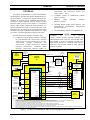
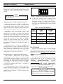
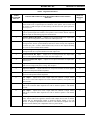
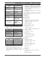
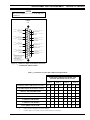
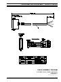
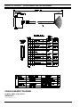
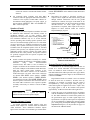
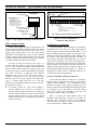
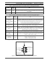
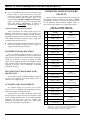
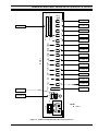
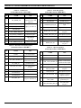
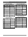
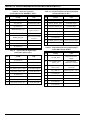
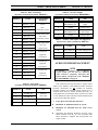
AE/LZB 119 1894 R1A ENHANCED AUDIO ENCLOSURE PIN-OUTS
q
If not accomplished in the previous instructions in this
manual, install a 4-wire balanced line (two pairs)
between the required CEC/IMC Audio Concentrator
Card and Enhanced Audio Enclosure. Refer to the
section entitled “CEC/IMC INTERCONNECTIONS”
(page 11). In most cases, the pre-wired 100-foot audio
cable (part number 19B804083P2) is utilized as
described in the “Audio Links” subsection (page 16).
ENHANCED AUDIO ENCLOSURE
PIN-OUTS
Tables 11 thru 27 list the pin-outs of the connectors on
the Enhanced Audio Enclosure's rear panel. "NAME"
designations in the tables correspond to the labeling used on
the I/O Backplane Board schematic diagram. Figure 12
shows the rear panel and serves as a guide to the table(s).
Table 11 – CEC/IMC Audio Lines
(female DB-25 labeled "LINES 1-4")
Console-to-Call Director Interconnections
Table 10 describes the various signals between the
Enhanced Audio Enclosure and the Call Director. The
descriptions are relative to the Enhanced Audio Enclosure.
All Enhanced Audio Enclosure connections are made at the
"CALL DIR" female DB-9 connector. Figure 11 and Table
12 indicate the connector's pin-out.
q
Interconnect the Enhanced Audio Enclosure to the Call
Director as required per Tables 10 and 12, Figure 11,
and the Call Director's documentation.
EQUIPMENT ROOM GROUNDING
Proper grounding techniques should be observed in
order to protect the equipment and service personnel from
lightning and other sources of electrical surges. All consoles
should be connected to properly grounded 3-terminal
outlets. If used, lightning arrestors, UPS equipment, and all
other console-associated equipment should also be properly
grounded. If necessary, refer to LBI-39067 for detailed
grounding procedures.
ELECTROSTATIC DISCHARGE (ESD)
PROTECTION
Always observe proper equipment handling procedures
to protect the equipment from ESD damage. Refer to
LBI-38737 for complete details.
AC POWER AND UPS EQUIPMENT
All consoles require 115 or 230 Vac (47 to 63 Hz)
power sources. As a minimum, each outlet should be circuitbreaker protected per local building codes.
UPS protection is optional. Maximum required UPS
wattage rating for a single console system should be based
on the required maximum sums of the Enhanced Audio
Enclosure (200 watts max.), the PC's computer (per
manufacturer's specifications) and the PC's video display
monitor (per manufacturer's specifications).
PIN
NAME
USE *
1
LINE_1_IN+
2
LINE_1_IN-
Line 1
balanced input
3
no connection
4
LINE_2_IN+
5
LINE_2_IN-
6
no connection
7
LINE_3_IN+
8
LINE_3_IN-
9
no connection
10
LINE_4_IN+
11
LINE_4_IN-
12
no connection
13
no connection
14
LINE_1_OUT+
15
LINE_1_OUT-
16
no connection
17
LINE_2_OUT+
18
LINE_2_OUT-
19
no connection
20
LINE_3_OUT+
21
LINE_3_OUT-
22
no connection
23
LINE_4_OUT+
24
LINE_4_OUT-
25
no connection
Line 2
balanced input
Line 3
balanced input
Line 4
balanced input
Line 1
balanced output
Line 2
balanced output
Line 3
balanced output
Line 4
balanced output
* With respect to the Enhanced Audio Enclosure. For
example, pins 1 and 2 are Enhanced Audio Enclosure line
inputs; audio signals on these inputs originate from the
CEC's/IMC's CIM line outputs. Also see Figure 6.
28