1
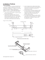
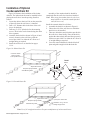
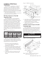
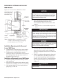
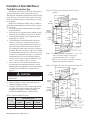
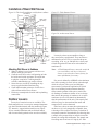
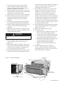
Installation of Basic Wall Sleeve Figure 24. Thick wall installation with hydronic subbase Figure 25. Flush Stamped Louver See Table 2, page 16 Steel Lintel (by others) Caulk Perimeter 1" (25mm) Wall Sleeve 133/4" (349mm) Mounting Screws (by installer) Outside Louver 16" (406mm) Wall Sleeve Extension Room Cabinet 81/4" (209mm) Figure 26. Architectural Louver 17" (432mm) Hydronic Heating Coil 81/4" (209mm) Floor Hydronic Subbase Attaching Wall Sleeve to Subbase 1. 2. 3. 4. 5. Where a subbase is used, secure wall sleeve to subbase with clips provided. Caulk the wall sleeve to the wall opening on both the inside and outside perimeter. Be careful not to plug the weep holes. Caulking should be resilient, nonhardening type such as silicone. Secure the two sections by installing the clip screws supplied with the hardware bag. Caulk indoor/outdoor perimeter of wall sleeve with resilient caulk such as silicone. Finish any uncompleted electrical and/or plumbing connections. Outdoor Louvers Two styles of exterior louvers are available. The flush stamped louver is a one-piece stamped aluminum type that is finished natural and clear anodized (Figure 25). Attractive, rugged architectural louvers (Figure 26) are extruded aluminum and are finished natural and clear anodized (optional colors are also available). Louvers by others are acceptable as long as they meet factory specifications. They must have a minimum free area of 70% or a pressure drop not exceeding .05 in. w.g. at 300 fpm face velocity and a blade design that will not cause recirculation of condenser air. Note: A Flush Stamped Louver cannot be used with a recessed louver wall sleeve. Recessed Louver is special order. Contact factory for more information if necessary. Free area is defined by ASHRAE as the minimum area of the openings in an air inlet or outlet through which air can pass. Have your local McQuay representative evaluate the application of special louvers or building facade treatments that may affect normal operation of the unit or restrict free air discharge of condenser airflow. A louver design that restricts the passage of condenser air or causes condenser air to be recirculated can dramatically alter the performance of the unit. Unit capacity and efficiency may be decreased and fan motor and compressor life can be shortened. If the louver does not meet the requirements set out above or it is only marginally acceptable, then a drawing will be required for factory evaluation. If acceptance cannot be determined by the drawing, then a sample of the proposed louver must be sent to the factory for testing and certification. The sample sent for testing must be at least 16" high by 42" wide. IM 934 Applied PTAC / Page 17 of 44