1
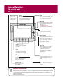
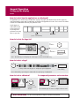
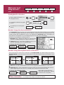
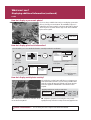
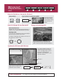
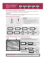
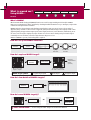
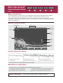
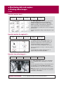
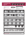
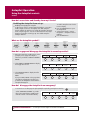
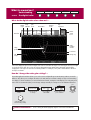
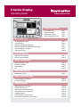
E-Series Display
Operating Guide
www.raymarine.com
PAGE
ACTIVE
WPTS
MOB
DATA
MENU
General Operation
OUT
RANGE
IN
OK
CANCEL
The control panel
Using the controls
Setting up the display
Using CompactFlash cards
Card 1
Card 2
Card 3
Card 4
What can I see?
Understanding the chart
Using the chart
Displaying additional information
Displaying additional information (continued)
Understanding the 3D chart
Using the 3D chart
Card 5
Card 6
Card 7
Card 8
Card 9
Card 10
Basic Navigation
Working with waypoints
How do I get to a point?
Card 11
Card 12
What is around me?
Understanding the radar
Avoiding a collision
Using MARPA
AIS
Card 13
Card 14
Card 15
Card 16
Where am I going?
Monitoring a course
Card 17
What's under the boat?
Understanding the fishfinder
Using the fishfinder
Card 18
Card 19
Monitoring data and engines
Viewing video images
Navtex and Sirius Weather Data
Sirius Weather Data (continued)
Autopilot Control
Understanding tha digital radar
Operating a networked E-Series Display
Card 20
Card 20
Card 21
Card 22
Card 23
Card 24
Card 25
D6721_5
Other functions
General Operation
The control panel
Card 1
DATA
Press to access
ruler, chart vectors,
archive & transfer
and data bar
on/off functions.
ACTIVE
When multiple windows are open:
- Press to select required window.
- Press and hold to maximize current
window.
- Press again to return to multiple
windows.
PAGE
Press to scroll through available pages.
Press and hold to select different page
set or customise your own layout.
PAGE
ACTIVE
WPTS
MOB
DATA
WPTS/MOB
Press to display the waypoint soft keys.
Press again to place waypoint at your
boat's position.
Press and hold to place a
Man Overboard (MOB) marker at
your current position. Press and hold
again to exit MOB.
MENU
MENU
Press to access the set up menus.
OUT
RANGE
IN
OK
Softkeys
Press to select the corresponding
function identified by the onscreen label
Power
Press once to turn ON.
Press again to access backlight
functions and scanner controls.
Press and hold to turn the display
OFF.
RANGE
Press to change the display scale
so that a smaller or larger area
can be seen on the screen.
Chart Card slot
Open the cover to install
CompactFlash cards.
CANCEL
Rotary control
Use to edit alpha-numeric values, and
scroll through lists.
Turn clockwise to increase value and
counter-clockwise to decrease value.
Press to move the cursor to the next
character when editing text.
Use to edit symbology (VRM/EBL etc).
Trackpad
Used to control the on-screen cursor
and to scroll through menu items.
Press the corresponding edge of the
trackpad to move the cursor
horizontally, vertically or diagonally.
Press and hold to move rapidly over
larger distances.
CANCEL
Press to cancel the selected on-screen
option when editing data; also used to
return to the previous soft key set or
menu.
OK
Press to select an on-screen option, or
return to the previous set of soft keys
or menu.
This unit is only an aid to navigation. Its accuracy can be affected by many factors, including equipment failure
or defects, environmental conditions, and improper handling or use. It is the User's responsibility to exercise
common prudence and navigational judgements. This unit should not be relied upon as a substitute for such
prudence and judgement.
Always keep a proper look-out.
D7523_2
WARNING: NAVIGATION AID
General Operation
Using the controls
Card 2
How do the controls work?
Buttons
PAGE
Access system functions or change what you see on-screen.
Within the text of this document they are written in bold capitals
e.g. WPTS/MOB.
ACTIVE
WPTS/
MOB
DATA
Press and hold to access short cuts - see individual buttons on
facing page.
MENU
Example:
This example shows
the series of button
and soft key presses
required to change
the waypoint default
symbol or group.
Soft keys
They change depending on application or
function being performed.
WAYPOINT AT
CURSOR
WAYPOINT AT
VESSEL
WAYPOINT AT
LAT/LONG...
GO TO WAYPOINT
OPTIONS…
REVIEW AND EDIT
WAYPOINTS
ERASE WAYPOINT
SORT LIST
SET DEFAULT SYM
& GROUP...
WAYPOINT
GROUPS...
VIEW AND EDIT
DETAILS…
Press and hold MENU to display help
information for the currently displayed
soft keys.
Press the corresponding key (below the
screen) to select.
Further soft keys may be displayed.
If a key has several options, each press
will highlight the next option.
If a key displays a single value or a slider
above, use the rotary control to adjust.
SET UP DEFAULT
SYMB GROUP
EDIT DEFAULT
Within the text of this document they are
written in capitals e.g. SORT LIST.
This process of pressing buttons and soft keys to navigate to the required function, is simplified within this
guide and represented by a strip e.g.
WPTS/
MOB
REVIEW AND EDIT
WAYPOINTS ...
SET DEFAULT SYM
& GROUP...
SET UP DEFAULT
SYMB GROUP
D7366-1
The Cursor
The Cursor appears on the screen
as a white cross.
To make it easier to locate on screen, the cursor
changes to a circle with a cross in it, when it is moved
after a 10 second period of inactivity.
The cursor is context-sensitive. When it is placed over an object e.g. a waypoint or chart feature, it
changes color and a label or information associated with the object is displayed. When you place
WPT the cursor over certain items, the soft keys change to enable you to access related operations.
To practice using your Display without data from a GPS, scanner or fishfinder, switch on the simulator via the
System Setup menu.
D6762_4
Simulator:
General Operation
Setting up the display
Card 3
How do I select how the applications are displayed?
The applications are shown using a combination of page sets, pages and windows. There are five page sets
each containing five pages with a combination of windows and applications in each. These sets can be edited
to define the combination that suits your particular needs.
Any changes you
make will be saved
to the system. You
can change these
preferences as many
times as you wish.
Page
(1, 2, 3 or 4 windows)
Window
How do I select the Page Set?
To
confirm...
OK
Or
PAGE
Press
and hold
Highlight
required page
set.
To
customise...
EDIT PAGE SET
Follow on-screen
instructions
Note: Alternatively you can display the Select Page Set screen via the Menu key.
How do I select a Page?
PAGE
SOFT KEY
Press appropriate soft key
Soft keys reflect current page set. Displayed option highlighted
Note: Alternatively, repeatedly press PAGE until the required page is highlighted.
ACTIVE
The active window
is bordered in red
Press to move
highlight to next
window
To temporarily maximise active window:
ACTIVE
Press
and hold
Press ACTIVE again to return to multiple windows mode.
? More information - See the 'General Operation' chapter of the Reference Manual
D8990_2
How do I select a Window?
General Operation
Using CompactFlash cards
Card 4
CAUTION
CompactFlash Card
In order to protect your E-Series Display and CompactFlash cards from irreparable
damage, please adhere to the following:
Fit the card the correct way around. DO NOT force.
Ensure card door is firmly closed at all times.
DO NOT use a metallic instrument (e.g. screwdriver or pliers) to aid card removal.
Follow the correct procedure for removing a card (see below).
DO NOT remove card during either a read or write operation.
How do I insert a CompactFlash card?
1. Check that you are using the correct type of card.
Raymarine recommend Navionics Chart cards or
SANDISK CompactFlash cards.
Narrow
Groove
2. Open the chart card door, located on the front left
of the display.
Lip
3. Insert the card as shown, with the lip of the card
facing inwards. It should position easily. If it does
not, DO NOT force it, check the direction in which
the lip is facing.
4. Gently press the card home and then firmly click
the chart card door shut.
How do I remove a CompactFlash card?
... with the unit powered
... with the unit powered down
1. Press MENU. The Setup menu is displayed.
1. Open the chart card door.
2. Use trackpad (up/down) to highlight and then
(right) to select CF CARD REMOVAL. The system
will now complete its checks.
2. Grip the card and pull to remove it from its slot.
3. Firmly click the chart card door shut.
3. When instructed to do so, open the chart card
door and remove the card.
? More information...
See the 'General Operation' chapter of the Reference Manual.
D6724_4
4. Firmly click the chart door shut and press OK
twice.
What can I see?
FIND
SHIP CURSOR
Understanding the chart
GOTO
ROUTES
TRACKS
PRESENTATION
Card 5
What can I use the chart for?
Find where you are.
Interpret your surroundings.
Place waypoints at specific locations.
Navigate to a specific point.
Monitor where you are going.
Record where you have been.
Measure the distance between two points.
Chart
range
Chart
orientation
4nm
North-Up
Build and follow routes.
Manage and edit routes and tracks.
Distinguish between fixed & moving objects
(radar overlay).
View photographs of ports and marinas.
View information normally contained in an almanac.
Display an aerial photo overlay.
Motion
mode
Chart
view
(Relative Motion)
Local
Status bar
Chart boundary
Gully Ridge
Route
Portside
Cursor
Port point
Creek point
Waypoint
Active waypoint
Current position
Cartographic object
Track
How do I move around the chart?
To change the scale:
OUT
RANGE
IN
To pan the chart:
Press RANGE (OUT) to see a larger
area of the chart.
Press RANGE (IN) to see a smaller
area in more detail.
Moves cursor. When cursor reaches
window edge, chart pans to a
different area.
Press and hold to pan larger areas.
How do I find where I am on the chart?
? More information...
See 'Using the Chart' chapter of the E-Series Reference Manual
D8978_2
The boat symbol
indicates your
position.
If you cannot find your boat symbol :
The screen automatically pans to your
boat's position and re-activiates the motion
FIND
mode (see below - 'How do I change how
SHIP CURSOR
my boat moves on the chart').
What can I see?
FIND
SHIP CURSOR
Using the chart ...
GOTO
ROUTES
TRACKS
PRESENTATION
Card 6
Viewing detail on the chart
Display additional information on a
cartographic feature:
OK
OK
For more
information
Setup
To show/hide individual cartographic
features:
MENU
To show/hide pre-set cartographic
features:
PRESENTATION...
Cartography Setup...
OFF
ON
DECLUTTER
ON
OFF
How do I change the chart orientation?
The orientation of the chart refers to the relationship between the chart and the direction you are travelling
in. It is used in conjunction with motion mode (see below) to control how your boat and chart relate to one
another and how they are displayed on screen. The default mode is North Up (N-UP). This displays your
chart with true north upwards. As your heading changes the boat symbol moves accordingly.
If desired, you can change the orientation mode to:
Head Up (H-Up) - displays chart with boat's current heading
upwards. As heading changes, boat symbol remains fixed
Course Up (C-Up) - chart picture stabilized, current course
upwards. Boat symbol moves as heading changes.
To change the orientation mode:
PRESENTATION...
CHART MODE AND
ORIENTATION...
ORIENTATION
H-UP N-UP C-UP
Toggle as required
How do I change how my boat moves on the chart?
How your boat moves on the screen is referred to as the motion mode. The default setting for the chart is
Relative Motion. This means that your boat is fixed on the screen and the chart moves relative to your
boat i.e.
If desired, you can change the motion mode to:
True (TM) - the chart is fixed and the boat moves in true perspective to fixed landmasses on the screen.
Autorange (AR) - selects and maintains the largest possible scale of chart that will display both the boat
and the target waypoint This option is not available when radar/chart synchronization is ON.
PRESENTATION...
CHART MODE AND
ORIENTATION...
? More information...
MOTION MODE
TM RM AR
NOTE: When you pan the chart or
toggle FIND SHIP/CURSOR to CURSOR,
the motion mode is suspended.
See 'Using the Chart' chapter of the Reference Manual
D6740_4
To change the orientation mode:
What can I see?
Displaying additional information
Card 7
Viewing object information
OK
More detailed information for
selected object displayed.
Move cursor over object, to
display basic information.
You can now:
Locate the nearest waypoint, port, port service,
tidal and current stations, wreck or obstruction, to
the selected position.
View detailed data for the selected port, tidal or
current station.
View panoramic photographs (dependent on the
type of chart card in use)
Search for a named port.
Finding nearby features and services:
1.
OK
FIND NEAREST...
Move cursor to
required position
SELECT PORT
FIND NEAREST...
2.
SELECT PORT
WAYPOINTS
PORTS
PORT SERVICES
TIDE STATIONS
CURRENT STATIONS
WRECKS
OBSTRUCTIONS
FIND
Select required
category
16 nearest to cursor in selected
category displayed.
Displaying port services:
OBJECT INFO
RAINBOW MARINA
Photos
Pilot Book
OK
Select appropriate
port symbol
Position
29058'.147N
093052'.215W
Utilities
Banks
Restaurants-Bars
Supplies
Hookups
Fuel
SEARCH BY NAME
Or
Note:
Alternatively you can search
for port by name
Services for selected port displayed
Displaying tidal and current details:
TIDE DATA
OBJECT INFO
MILE POINT Position 30006'.700N
84012'.700W
Or
T
OK
Ebb
Flood
Ebb
Flood
05:41AM
01:08AM
06:17AM
11:30AM
+187.0
+358.0
+0.0
+358.0
Current information
displayed
? More information...
0.5kt
0.2kt
0.0kt
0.2kt
Or
CURRENT DATA
Graph page displayed
See the 'Using the Chart' chapter of the Reference Manual.
D8849_2
C
What can I see?
Displaying additional information (continued)
Card 8
How do I display a panoramic photo?
If you are using a suitable chart card, you can display a panoramic
photo(s) of many ports and marinas. The availability of photos is
indicated by the camera symbol on the chart. This symbol is placed
where the photo was taken and the angle of the shot is indicated
by the camera symbol.
OK
VIEW PHOTO
Select required
camera symbol
How do I display pilot book information?
This will enable you to view detailed information normally contained in an almanac..
1.
OBJECT INFO
OK
Select
appropriate
port symbol
RAINBOW MARINA
Photos
Pilot Book
Position
29058'.147N
093052'.215W
Book5, Chp5
Highlight and select the pilot
book option
2.
OBJECT INFO
0
Position 29 58'.147N
093052'.215W
RAINBOW MARINA
Photos
Pilot Book
Book 5, Chp 5
VIEW PILOT BOOK
Highlight required
book/chapter
Selected book/chapter
displayed
How do I display aerial photo overlay?
The aerial photo overlay feature will help you to interpret your
environment and its features. If you are using a suitable chart
card, this overlay will appear by default on 3D chart windows
and can be applied to individual 2D chart windows when
required.
Applying aerial photo overlay to a 2D chart:
PRESENTATION…
AERIAL OVERLAY
ON
OFF
CHART LAYERS...
Enable soft key
? More information...
See the 'Using the Chart' chapter of the Reference Manual.
D8841_2
3D - Aerial photo overlay can be switched off via 2D - Adjust the opaqueness level using the rotary control.
the 3D Chart Setup Menu.
Specify land only or land/sea overlay via the cartographic menu.
What can I see?
FIND SHIP
ADJUST ON
EYE
CENTRE
GOTO
Understanding the
3D chart
ADJUST
ROTATE PITCH
PRESENTATION
Card 9
What can I use the 3D chart for?
If you are using a suitable chart card you will be able to:
Synchronize the 2D and 3D chart.
Display a 3D view of land, sea &
features.
Locate where you are.
Interpret your surroundings.
Monitor where you are going.
Range
Mode
Go to an existing waypoint.
Navigate a route.
Rotation
Status bar
North arrow
Cartographic objects
Center-of-view
Active waypoint
(with arrival circle)
Boat symbol
Depth scale
How do I move around the 3D chart?
To change the scale:
Press RANGE (OUT) to see a larger
area of the chart.
Press RANGE (IN) to see a smaller
area in more detail.
To adjust rotation/pitch
OUT
RANGE
1. Select rotate
or pitch:
ADJUST
ROTATE PITCH
Or
Press
IN
Toggle control to
required function
Turn
To pan the 3d chart:
To pan a 3D chart to a different
area
Rotates the view or
changes the vertical
angle of view.
2. Adjust the
rotation/pitch:
Changing the view on the 3D chart
To enhance objects and make it easier to see their shape and position:
2
To show/hide pre-set cartographic features:
PRESENTATION...
DECLUTTER
ON
OFF
? More information...
ADJUST
EXAGGERATION
ADJUST
EXAGGERATION
Adjust
factor as
required
See 'Using the 3D Chart' chapter of the E-Series Reference Manual
D8735_2
PRESENTATION…
3D VIEW
OPTIONS...
What can I see?
GOTO
FIND SHIP
Using the 3D chart ...
ADJUST ON
EYE
CENTRE
ADJUST
ROTATE PITCH
PRESENTATION
Card 10
How do I find where I am on the 3D chart?
Your position:
Or
If you cannot see your boat symbol:
The 3D chart automatically redraws with the
boat in forward looking
view at your current
position.
FIND SHIP
How do I change the motion mode?
Using aerial photographs
Active motion mode
Default mode when 3D chart opened and there is a
valid fix. Shows aerial view from above your boat.
Planning mode:
To view an area of the chart you are not currently in.
The boat may not remain on the screen.
To change to planning mode and pan to the area of
the 3D chart you want to view:
Turn
The aerial photograph overlay helps you to
interpret features in your environment. This
option is accessed via the 3D Chart Setup menu.
Or
Synchronize 3D chart with 2D chart
Note: When multiple windows are
displayed and the current window
is set to SYSTEM, changes made to
the chart are reflected in all
windows. If set to LOCAL no other
window is affected.
3D location
Eye point
? More information...
PRESENTATION...
CHART MODE AND
ORIENTATION...
CHART SYNC
RDR 3D OFF
See 'Using the 3D Chart' chapter of the Reference Manual.
D8736_2
With a 2D chart window active,
synchronise 3D to 2D chart:
Basic Navigation
Working with Waypoints
WAYPOINT AT
CURSOR
WAYPOINT AT
VESSEL
WAYPOINT AT
LAT/LON
GO TO WAYPOINT
OPTIONS
REVIEW AND EDIT
WAYPOINTS
Card 11
What is a waypoint?
A waypoint is a position marked on a chart, radar or fishfinder screen to
indicate a site (for fishing, diving etc), or as a position to go to. You can
place a waypoint at the cursor or your boat's position or at a specified
position. Waypoints are represented in chart or radar applications as an
'X' (default) and by a vertical line labeled WPT in Fishfinder. Active
waypoints are displayed on 3D Chart and CDI windows. The details of
each waypoint are stored in a waypoint list. Waypoints can be renamed,
edited, grouped, or erased, as necessary. To make full use of waypoint
features, ensure your display is receiving heading and position data. We
recommend that you regularly back-up your waypoints by archiving them
to a CompactFlash card. Waypoints can also be transferred to another
NMEA compatible instrument.
Waypoint
Networked systems
If you have networked two or more
E-Series Displays, the waypoints are
stored on the master display and
transferred to other displays via the
SeaTalk High Speed network.
How do I place a waypoint?
... at the cursor?
... at the vessel?
WAYPOINT AT
CURSOR
WPTS/
MOB
WAYPOINT AT
VESSEL
WPTS/
MOB
WPT
Move cursor
to position
Alternatively, press WPTS/MOB twice.
How do I navigate to a point?
GOTO...
CAUTION
GOTO CURSOR
Always check that your route to a waypoint
is safe before travelling towards it.
Move cursor
to position
How do I navigate to a waypoint?
...using the waypoint list?
Waypoint list
GO TO WAYPOINT
OPTIONS...
WPTS/
MOB
Name:
Waypoint 1
Waypoint 2
Waypoint 3
Group:
My Waypoint
Position:
50 53’.826N
o
001 10’.963W
Rng/Brg:
284
Temperature:
Depth:
Date:
Time:
...using the cursor?
GO TO WAYPOINT
o
o
4.315nm
---.-O F
---.-ft
05/11/2003
14:59:11
Highlight
required waypoint
To stop navigation to a waypoint:
GO TO WAYPOINT
WPT
Place cursor
over waypoint.
GOTO...
STOP GOTO
OR:
WPT
Move cursor to
required position
Can I edit a waypoint?
? More information...
Erase a waypoint
See the 'Working with Waypoints' chapter of the Reference Manual
D6729_4
Once a waypoint has been placed it can be edited in as variety of ways. You can:
Change the default group or symbol
Change the waypoint details Move a waypoint
Basic Navigation
How do I get to a point?
SHOW/HIDE
ROUTES
FOLLOW ROUTE
OPTIONS
REVIEW AND EDIT
ROUTES
BUILD NEW
ROUTE
Card 12
What is a route?
A route is made up of a series of waypoints. These
waypoints can either be placed specifically for that route
and/or you can use existing waypoints. You can save a
route for future use or follow it immediately (Quick Route).
Routes are stored in a route list. If you have networked
two or more E-Series displays, the routes are stored in the
master display and are transferred to the other displays via
the SeaTalk High Speed network.
Routes can be named, edited, erased and archived. After
routes have been created you can choose which ones are
displayed on your chart.
Target waypoint
highlighted
Course from start point
to target waypoint
NORTH POINT
Remaining
legs of route
KNOLL
COWES
How do I build a route by placing waypoints on screen?
OUT
1.
BUILD NEW
ROUTE
ROUTE...
RANGE
IN
Move cursor into
appropriate area
Move cursor to
required position
for first waypoint
Select a
suitable scale
PLACE
PLACE WAYPOINT
WAYPOINT
2.
PLACE WAYPOINT
SAVE ROUTE
Move cursor to position
for next waypoint.
UNDO WAYPOINT
3.
OK
If you place a waypoint at the incorrect
position, press UNDO WAYPOINT.
How do I follow a route?
... from the route list
GOTO...
Route List
FOLLOW ROUTE
OPTIONS...
Color
-------------
Name
Quick Route
Route 1
Route 2
Route 3
FOLLOW ROUTE
Select route
... from the start of route
... from a selected waypoint within route
FOLLOW FROM
HERE
FOLLOW THIS
ROUTE
? More information...
Position cursor over
appropriate waypoint
See the 'Using the Chart' chapter in the Reference Manual, for more
information on routes.
D6730_4
Position cursor over any
leg of required route
What is around me?
VRM/EBL
Understanding the radar
TARGET
TRACKING
ENHANCE
ECHOES...
GAIN
PRESENTATION
Card 13
What does the radar show me?....
Range
Range ring spacing
Motion mode
Orientation
Data bar
3nm
Head-Up
Relative Motion
Rings ½nm
Icon
confirming
radar
connection
Range
ring
Ship's
heading
marker
Boat's
position
Surface
vessel
Waypoint
Landmass
VRM/EBL...
TARGET
TRACKING...
GAIN...
ENHANCE
ECHOES...
PRESENTATION...
Typically your boat's position is at the centre of the display, and its dead ahead bearing is indicated by a vertical
heading line, known as the Ship's Heading Marker (SHM).
Remember that the radar picture may vary from visual observations that you make; a nearby small object may
appear the same size on the screen as a distant large object. However, with experience the approximate size of
different objects can be determined by the relative size and brightness of the echoes.
How do I measure distances, ranges and bearings with the radar?
VRMs
Align a VRM on a target to
display its range from your
boat:
EBLs
Align an EBL on a target to
display its bearing relative to
your boat's heading:
e.g.
e.g.
ADJUST VRM
1.800nm
Combined VRM/EBL
Combine a VRM and EBL to
measure range and bearing of
specified target.
Rings 1/2nm Range rings
e.g.
ADJUST VRM
1.800nm
ADJUST EBL
30.00S
Use the range rings to gauge
the approximate distances
between two points or from
your boat.
ADJUST EBL
30.00S
? More information...
See the 'Using the Radar' chapter of the Reference Manual
D6731-4
Note: Range/bearing also displayed when VRM/EBL selected with the cursor.
What is around me?
TARGET
TRACKING
VRM/EBL
Avoiding a collision
ENHANCE
ECHOES
GAIN
PRESENTATION
Card 14
How can the radar help me avoid a collision?
You can set up your E-Series Display to sound an alarm when anything comes within a pre-set range of the boat.
These guard zones allow you to take any necessary action to avoid a collision.
Guard zones
A sector or circular zone fixed with respect to the Ships Heading Marker (SHM). If the SHM moves, or the centre is
offset, or the range scale changes, the zone moves accordingly.
What does a guard zone display?
SHM
SHM
IMPORTANT
A guard zone:
Will only operate when a whole zone is displayed on
screen, or displayed by offsetting the centre.
Is inactive for 10 seconds after it is placed or re-sized, to
avoid inappropriate alarms.
Circular Zone
Sector Zone
How do I set up a circular guard zone?
1. Select guard zone function:
TARGET
TRACKING...
ZONE 1
ON OFF
MONITOR IN
ZONES...
SET UP
ZONE 1
Toggle to ON
2. Select guard zone option:
ZONE SHAPE
SECTOR CIRCLE
Turn
Turn
SET INNER
xx.xx nm
OK
Toggle to
required shape
Turn to set
inner boundary
Turn to set
outer boundary
Press
How do I distinguish between fixed and moving objects?
Radar Range
12nm
Status
N-UP
(RM)
Ov
To switch radar overlay on/off:
Sys
You can overlay radar image data on your chart allowing better
distinction between fixed objects and other marine traffic.
With a 2D chart window active:
PRESENTATION...
CHART LAYERS
RADAR OVERLAY
ON
OFF
To switch chart/radar synchronization on/off
For best results, also switch on chart/radar sychronization.
With a 2D chart window active:
To change scanner
range in this mode:
CHART MODE AND
ORIENTATION...
RADAR
OPTIONS...
? More information... See the 'Using the Radar' chapter of the Reference Manual.
CHART SYNC
RDR 3D OFF
OUT
RANGE
IN
D8838_2
PRESENTATION...
What is around me?
MONITOR
IN ZONES
ACQUIRE TARGET
MARPA & AIS
OPTIONS
AIS LIST
MARPA LIST
Using MARPA....
Card 15
What is MARPA?
Mini Automatic Radar Plotting Aid (MARPA) functions are used for target tracking and risk analysis. MARPA
improves your standards of collision avoidance by obtaining detailed information for up to 10 targets, and provides
continuous and rapid situation evaluation.
MARPA tracks the selected targets and calculates target bearing, range, true speed, course, Closest Point of
Approach (CPA), and Time to Closest Point of Approach (TCPA). Each tracked target can be displayed with a CPA
graphic depicting the approximate target speed (vector length) and course (vector direction). Alternatively, move
the cursor over the target to display the range and CPA. You can now access bearing and speed. Each target is
continually assessed. An alarm sounds if a target becomes dangerous or lost.
NOTE: For MARPA to operate, fast heading data is required.
How do I set up the MARPA functions?
MARPA & AIS
OPTIONS...
TARGET
TRACKING...
OK
Highlight
and select
Select value
from list
How do I acquire a MARPA target?
TARGET
TRACKING...
ACQUIRE TARGET
Repeat to
acquire further
targets
(10 max)
1800T
2.3kt
Move cursor over
target to acquire
The target is acquired this takes a few seconds
Target being acquired
MARPA target symbols
Dangerous target
Safe target
How do I view details of MARPA targets?
MARPA LIST
TARGET
TRACKING...
MARPA LIST...
ID
Bearing
2
312oT
Range
True
Course
1.739nm
342oT
00h00m00s
o
9.4kt
22.7kt
1.305nm
1.774nm
00h00m00s
00h00m00s
o
1.305nm
1.774nm
276 T
321oT
4
5
086 T
247oT
TCPA
00h00m00s
3.242nm
335 T
274 T
CPA
1.739nm
68.4kt
3.242nm
3
True
Speed
9.9kt
o
o
Tracked targets with data listed.
How do I cancel MARPA target(s)?
CANCEL TARGET
Or:
MARPA LIST...
CANCEL ALL
TARGETS
? More information...
See the 'Using the radar' chapter of the Reference Manual.
D6733_4
CANCEL TARGET
What is around me?
AIS VECTOR
ON OFF
AIS DATA
AUTO ON OFF
VIEW FULL
AIS DATA
Using AIS
Card 16
AIS target symbols
What is AIS?
AIS uses digital radio signals to broadcast ‘realtime’
information between vessels and shore based stations
via dedicated VHF frequencies. This information is used
to identify and track vessels in the surrounding area and
to provide collision avoidance data. AIS will augment
your radar application, as it can operate in radar blind
spots.
In order to use the AIS feature, you will need a GPS and
compass for timing and position information together
with data from a suitable AIS receiver.
How do I display AIS?
On chart windows:
PRESENTATION...
AIS LAYER
ON OFF
CHART LAYERS...
Toggle as required
On radar windows:
PRESENTATION...
AIS LAYER
ON OFF
Toggle as required
How is AIS data displayed?
The AIS system displays other AIS equipped vessels in
the surrounding area as targets overlaid on a chart or
radar window. Up to 100 targets are displayed and are
scaled according to the size of the vessel. A vector
indicates the direction of travel of the vessel. As the
vessel’s status changes, the symbol for the target will
change accordingly.
You can view detailed AIS data, safety critical target
information, Alarm message (ALR) and Safety Related
Message (SRM) messages. You can also set up a safe
zone.
How do I view target information?
AIS DATA
AUTO ON OFF
125oT
7.7kt
01.30nm
12h15m30s
Sleeping target
Target not activated, dangerous or
lost.
Activated target
Target activated i.e. AIS vector
displayed.
Vector line (optional) shows predicted
distance travelled within given time.
Selected target
Target selected with cursor.
Can activate the target and view
detailed data.
COG/SOG
vector
Direction
of turn
Heading
AIS
Dangerous target
Targets within specified distance
(CPA) or time (TCPA).
Dangerous target alarm sounds
and target flashes.
Uncertain target
Calculated CPA/TCPA value uncertain.
Lost target
When signal of a dangerous AIS
target not received for 10 seconds.
Target orientated in COG or CSE
direction as appropriate.
Alarm sounds and target flashes
WARNING:
Smaller vessels do not have to be
fitted with AIS and whilst it is
mandatory for larger commercial
vessels to carry AIS, its use is not. You
should not assume that your AIS will
display ALL vessels in your area.
How do I view detailed AIS data?
AIS Target info: Sim Target 6
COG 142oT
MNSI 6
Name Sim Target 6
VIEW FULL
AIS DATA
Call sign
SOG 25,7kt
CPA
Last seen 01/01/2006 01:13:21A M
O
Lat 30 39’.702W
Lon 080o18'.702W
Hdg 159oT
--,---nm
Length --,---ft
Beam --,---ft
--,---nm
TCPA --h--m--s
IMO No
Dest
ETA
Status
--/--/---- --:--:--AM
Under Way Using Engine
Type Normal
? More information...
See the 'AIS' chapter of the reference manual for data classes and how
to customise this feature.
D8809_2
Draught --ft
Where am I?
Monitoring a course....
Card 17
How do I monitor my course?....
Your course is shown on the chart application whilst motion mode is active.
Using COG and heading vectors (Press DATA - CHART VECTORS - COG/HDG VECTORS).
Use the Course Deviation Indicator (CDI). With your display receiving accurate heading and position
information, you can monitor your course and accurately steer to a target waypoint.
What does the CDI show me?....
The CDI gives a graphical representation of your boat's course. This 'rolling road' format represents a width
of sea equal to the Cross Track Error (XTE) limits that you have specified in the Setup menu. As you travel
towards the target waypoint, the checkered pattern moves down the screen to simulate movement at a rate
proportional to your boat's speed.
Direction of
next waypoint
Target waypoint
Correction
arrow
Direction
to steer
Target way- On course
point name
line
What do the steering instructions tell me?
0ff course
On course
XTE
0.000nm
? More information...
Boat off center line.
Correction arrow(s) indicate direction to steer
to maintain course to target waypoint.
The greater the XTE, the more arrows.
See the 'Using the CDI' chapter of the Reference Manual
D6734_4
Boat on center line.
Zero XTE
XTE
0.027nm
What's under the boat?
Adjust P1
SINGLE
PRESET 2
DUAL
PRESET 3
SHALLOW
PRESET 4
DEEP
PRESENTATION
Understanding the fishfinder
Card 18
What's under the boat?
The fishfinder application, when connected to a suitable Digital Sounder Module (DSM) and transducer, will help
you to see fish, bottom structure and underwater obstructions. The image scrolls from right to left at an
automatically selected range and frequency to provide a record of the echoes seen. You can mark with a waypoint
any positions of interest that you may wish to return to. These waypoints are added to the waypoint list and can be
used by other applications.
What can I see on the screen?
Frequency modes
Transducer Mode
SINGLE
Frequency
Freq1: 200KHz-Auto
Freq2: None
Bottom of
transducer
F1: 200 kHz
Depth
markers
Bottom
Target
depth
50
68
Target
69
Bottom
depth
ADJUST P1
SINGLE...
PRESET 2
DUAL
PRESET 3
SHALLOW
PRESET 4
DEEP
PRESENTATION...
How do I interpret the bottom?
A thin line indicates a hard
bottom (sand)
A wide line indicates a soft
bottom (mud or seaweed cover)
Peaks and troughs, indicate an
uneven or rocky bottom or a wreck
Dark layers indicate strong signals; lighter layers weaker signals.
What influences target display?
? More information...
See the 'Using the Fishfinder' chapter of the Reference Manual.
D6735_5
The shape and size of echoes indicating targets, is influenced by a combination of:
Boat speed - flatter at slower speeds
Transducer frequency - broader at lower frequencies
Target depth - larger near the surface
Target size - larger targets return larger echoes
What's under the boat?
Adjust P1
SINGLE
PRESET 2
DUAL
PRESET 3
SHALLOW
PRESET 4
DEEP
PRESENTATION
Using the fishfinder....
Card 19
How do I change the range or shift the image?
Your system automatically adjusts the display depth range, selecting the shallowest depth that keeps the
bottom on the lower half of the window. You can however, set this manually if required and move the image
within the selected page up or down. Using the range controls will affect all fishfinder windows.
Turn
OUT
OUT
RANGE
D6585-1
IN
RANGE
AUTO MAN
RANGE SHIFT
xx FT
RANGE
D6585-1
IN
IN - decrease depth.
OUT - increase depth.
Press RANGE
(IN or OUT)
Turn to alter
value.
How do I change Presets?
The Fishfinder application window allows you to have up to 4 user configurable preset modes, this allows
you to select and configure the transducer frequency and screen view's (see E-Series reference manual
section 6.6 Display mode settings, and section 6.10 Editing presets).
NONE
ZOOM
A- SCOPE
BOTTOM LOCK
ADJUST P1
SINGLE
ADJUST
FREQ1 FREQ2
SELECT VIEW
ZOOM
Select the preset
to change
Highlight required view
with trackpad
Use the softkeys to select the different modes (unless instructed otherwise)
Turn
ZOOM
FULL SPLIT
ZOOM FACTOR
x2 x3 x4 xR
ZOOM POSITION
AUTO MAN
Select required
zoom mode
Select required
zoom range
Select required
zoom position
OK
Turn to alter
value
How do I change the gain mode?
The system automatically adjusts the gain control to display the sharpest image. If required, you can select
the gain level to suit your fishing mode:
Low - when cruising
Med - when trolling
High - when fishing
CRUISING (LOW)
TROLLING (MED)
FISHING (HIGH)
PRESENTATION...
GAIN ...
GAIN MODE
AUTO MAN
Highlight required
preset
OK
COLOR GAIN
AUTO MAN
Select gain level
? More information...
See the 'Using the Fishfinder' chapter of the Reference Manual.
D6736_4
To define the gain mode still further, and to define other settings available on this page, select manual gain
mode and then adjust the level using the rotary control.
Monitoring data and engines
Viewing video images
Card 20
How do I monitor data?....
NAVIGATION
WAYPOINT
ROUTE
FISHING
SAILING
The data application enables you to view numeric
data generated by the system or by instruments
available on NMEA 0183, SeaTalk, SeaTalk2, NMEA
2000 and SeaTalkhs. This information is displayed in a
series of panels which contain data relating to a
particular function or activity. These can be reconfigured
to your needs.
Press the appropriate soft key to select the panel of your
choice.
How do I monitor the engine(s)?....
ENGINE
ENGINE & FUEL
FUEL RESOURCES
ENGINE &
RESOURCES
TWIN ENGINE
The engine monitor application enables you to
view data from up to three compatible engines. The
information is displayed in a series of panels which
contain data relating to engine, fuel and fuel
resources. These can be reconfigured to your needs.
Press the appropriate soft key to select the panel of
your choice.
To view data from 3 engines, change the 'No. of
engine' setting in the Panel Setup Menu
How do I view video images?....
VIDEO 1
VIDEO 2
VIDEO 3
VIDEO 4
PRESENTATION
The video application enables you to view images
from a satellite TV, video or DVD player or on-board
camera.
Press the appropriate soft key, to select the video input
of your choice or set CYCLE VIDEO to ON (via the
PRESENTATION key), to cycle through the video inputs.
? More information...
See the appropriate chapter of the Reference Manual.
D7521_4
Note: Video images can only be viewed on the display
to which the video source is connected. They cannot be
networked to other Displays.
Navtex and Sirius Weather Data
Card 21
Navtex
If connected to a Navtex receiver, you can use your display to view navigation, meteorological and search
and rescue alerts. You can choose which category of alerts will automatically be displayed when one is
received by your display. After you have read the message you can either erase it or save it to the database
(100 maximum). You can view the list of saved messages at any time. Messages are viewed and alerts setup via the Setup Menu option Navtex Messages.
Viewing saved messages
1.
Setup
Chart Setup...
Cartography Setup
MENU
AIS Layer Setup...
Navtex Messages......
Highlight and select
Navtex messages
Highlight required
item in list
Navtex Message List
Date
Time
Message ID
Navtex Message List
Message
Date
Time
Message ID
Message
2.
Associated message displayed
in message box
Move control to
message box
Scroll through message
(if applicable)
The Sirius Weather application (USA only)
To run the Sirius Weather application you will
need to purchase an SR100 weather receiver and
a subscription to Sirius weather.
Once connected, the weather application
superimposes historical, current and forecasted
weather graphics and environmental conditions
on the world map and provides textual forecasts
and warnings. These help you to determine the
actual conditions in your vicinity or at a particular
location.
As in the chart application, use the cursor to
move around the map and view different
locations, and the range button to zoom in and
out.
Range
Surface
observation Marine
Time data
zone
stations
Wave
heights
12:00 22/11
2400 nm
Signal
strength
Medium
To re-center the map on your boat use the FIND
SHIP soft key.
? More information...
FIND SHIP
DISPLAY
GRAPHICS...
ANIMATE
WEATHER...
WEATHER
REPORTS...
PRESENTATION...
Weather soft keys
See the appropriate chapter for the Reference Manual.
D8932_3
Note: As with all weather services, the
information presented is advisory only and you
should be aware that errors may occur.
Note: If you have an SR100 connected, you can
also control your Sirius satellite audio via your
E-Series display.
Sirius Weather Data
DISPLAY
GRAPHICS
FIND SHIP
WEATHER
REPORTS
ANIMATE
WEATHER
PRESENTATION
(continued)
Card 22
By default, all weather graphics are
set to OFF.
To display the required weather
graphic:
Weather Graphics
NOWRad
Storm Cast
Sea Surface Temp
Canadian Radar
DISPLAY
GRAPHICS...
id
Flor
26
OFF
ON
Highlight, select and switch graphic
on/off as required
Weather symbols (USA only)
24
OFF
OFF
OFF
OFF
a
22
Or
22
Cu
ba
Canadian radar
(light green- dark red)
Waves
(blues-green-red)
Storm cast
Wind
(see below for details)
Rain (green-yellow-red)
Snow (blues)
Mixture (pinks)
Marine zones
ida
Flor
Lightning
(light-med-dark yellow)
NWS
Buoy C-man
WST
Sea surface temperature Surface observation station
(pink)
(blue-green-yellow
-orange-red)
Cities (grey)
Surface pressure
High pressure (blue)
High pressure (red)
Warm front (red)
Cold front (blue)
Occluded front (purple)
1010
1012
Stationary front (red-blue)
Trough (brown)
Squall line (red)
Storm Tracks symbols
Shown in three different colours:
Grey - historical
Red - current
Orange - forecast
Note: Highlight the symbol for additional information
Dry line (brown)
Hurricane
(Category 1-5)
Tropical
storm
Isobars (grey)
Tropical disturbance
or tropical depression
Wind speed symbols (knots)
etc.
13-17
18-22
23-27
28-32
33-37
? More information...
38-43
44-47 48-52
53-57 58-62
63-67
68-72
73-77 78-82 83-87
88-93 94-97
See the Weather (USA only) chapter of the Reference Manual.
98-102
D8810_2
3-7 8-12
Autopilot Operation
Using the Autopilot controls
Card 23
How do I access Auto and Standby from my E-Series?
Enabling the Autopilot from set up:
To enable autopilot control on the
E-Series display:
Press the MENU button to open
the Setup Menu.
Select System Setup > System
Integration > Autopilot Control >
Enabled.
Press the OK button.
Enabling and engaging the autopilot
To allow the E-Series to control autopilot functions, you need to
enable autopilot control on the display unit. With autopilot
control enabled, the unit lets you engage the autopilot whenever
it has a target waypoint. You can see information for the target
waypoint on the Pilot Control pop-up. The default autopilot
setting is disabled.
What are the Autopilot symbols?
Wind Vane
mode
Power Steer
mode
Pilot Alarm
mode
Auto
mode
No Pilot
connected
Track
mode
Standby
mode
How do I engage and disengage the Autopilot in normal operation?
When the autopilot is enabled, the E-Series
prompts you to engage the autopilot
whenever you initiate a GOTO or FOLLOW
ROUTE.
Select GOTO or FOLLOW ROUTE to display
the Engage Pilot screen.
SHIP
FIND
CURSOR
AUTO
GOTO
GOTO CURSOR
Select ENGAGE PILOT to display the Pilot
Control screen.
NOTE:
If you press OK, CANCEL or the page times
out without engaging the autopilot, you
go back to the navigation screen with the
autopilot disengaged.
AIS OPTIONS
NAVIGATION
OPTIONS
FOLLOW ROUTE
OPTIONS
GOTO WAYPOINT
OPTIONS
ENGAGE PILOT
TRACK
PRESENTATION
STANDBY
How do I disengage the Autopilot in an emergency?
You can choose to disengage the pilot quickly if required by pressing the Power key
? More information...
See Autopilot control chapter of the Reference Manual.
AUTOPILOT
STANDBY
D10686_1
Select 'AUTOPILOT STANDBY' to put the
pilot in the autopilot into standby mode
and take control of the helm manually
What is around me?
TARGET
TRACKING
VRM/EBL
Understanding
the digital radar
Card 24
ENHANCE
ECHOES...
GAIN
PRESENTATION
What do the digital radar colors show me?....
Preset
Dual
gain
Radar range
range indicator mode
Orientation
Motion
mode
Range
ring
separation
Radar
status
Icons
Data bar
Ships
heading
marker
Ships
position
Land mass
AIS
target
Range ring
The colors displayed represent the strength of the echoes received from targets. For most targets the echo strength
is closely related to their size. Colors also help to distinguish targets within Clutter. Normally, targets will be
displayed as a stronger color than the surrounding clutter. For example, a Buoy with a radar reflector will show
clearly in sea clutter.
How do I change the radar gain settings?....
The Radar application window allows you to select 4 user configurable preset modes, Buoy, Harbour, Coastal &
Offshore. They allow you to configure the Gain, Color Gain, Rain & Sea Clutter settings to aid you in customising
the display to suit the conditions (see E-Series Reference manual, 'Tuning the radar display'). For each gain preset,
Auto mode is recommended, but you can change settings manually for each preset to suit individual situations.
24
GAIN...
COASTAL MODE
GAIN
AUTO MAN
GAIN
AUTO MAN
Select the Gain
softkey
Select the mode
to change
Select softkey,
select MAN
Change value to suit
your conditions
Turn
Turn to alter
value
OK
? More information...
See the 'Using the Radar (Digital)' chapter of the Reference Manual
D10703_1
Select the ok to save
manual setting softkey
Operating a networked E-Series Display
Card 25
What does a networked system do?
If you have connected two or more E-Series Displays (via either a crossover coupler or SeaTalk High Speed
Switch), all system data (from NMEA 0183, SeaTalk, SeaTalk2, NMEA 2000, SeaTalkhs waypoints, routes etc)
can be transferred across the network enabling you to input, view and maintain data across all your displays
irrespective of the Display from which the data originated (excepting Video Input).
How is the network controlled?
The display that has been installed and nominated as the master, should always be switched on (preferably
first). The master display maintains the waypoint, route and track lists as well as data from NMEA and
SeaTalk. Each time the master display detects a change on any display e.g. waypoint, route or track added or
edited, the data is copied to the database which in turn is copied to all other Displays that are switched on.
If the system does not detect a master, either because it is not switched on or because a master has not been
selected, an alarm will sound and you will be prompted to set a master display.
How do I change the master display?
MENU
Setup
Chart Setup....
Cartogrphy Setup....
AIS setup....
System Setup....
Alarm Setup....
GPS Status....
Highlight System
Setup
Select
System Setup Menu
Position Mode...
Lat/Long
TD Setup...
Simulator
ON
Bearing Mode
True
MOD Data Type
Position
Variation Source
Auto(05oW)
Manual Variation
00oE
Language
English (US)
Extended Character Set
OFF
System Integration setup Menu
DCM Message
Seatalk
Data Master
Bridge NMEA Heading
NMEA Output Setup....
ON
ON
ON
OFF
OFF
ON
Highlight Data Master
Ground Trip Reset...
Settings Reset...
Settings and Data Reset...
Select
Date/Time Setup...
Unit Setup...
System Integration...
Waypoint Password Setup...
Select ON
Highlight System Integration
Raymarine Ltd
Quay Point
Northarbour Road,
Portsmouth, Hampshire
England PO6 3TD
+44 (0)23 9269 3611
www.raymarine.com
Raymarine Inc.
21 Manchester Street,
Merrimack,
NH 03054-4801
USA
1-603 881 5200
www.raymarine.com
D8487_2
Select
Document No 86114_4