1
ST7LITE20F2 ST7LITE25F2 ST7LITE29F2
I/O ports
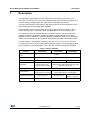
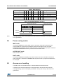
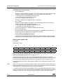
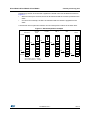
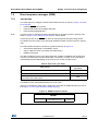
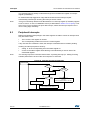
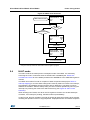
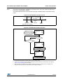
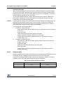
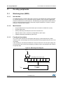
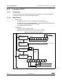
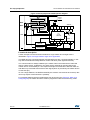
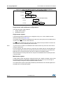
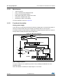
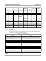
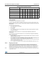
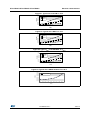
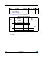
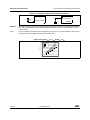
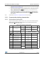
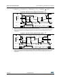
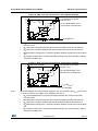
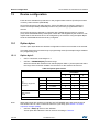
Figure 32. Interrupt I/O port state transitions
01
00
10
11
INPUT
floating/pull-up
interrupt
INPUT
floating
(reset state)
OUTPUT
open-drain
OUTPUT
push-pull
XX
10.4
= DDR, OR
Unused I/O pins
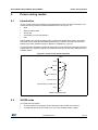
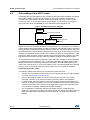
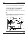
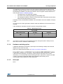
Unused I/O pins must be connected to fixed voltage levels. Refer to Section 13.8: I/O port
pin characteristics.
10.5
Low power modes
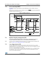
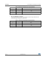
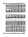
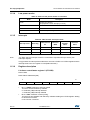
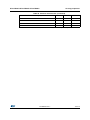
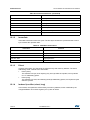
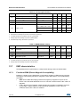
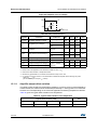
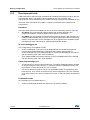
Table 24. Effect of low power modes on I/O ports
10.6
Mode
Description
WAIT
No effect on I/O ports. External interrupts cause the device to exit from WAIT mode.
HALT
No effect on I/O ports. External interrupts cause the device to exit from HALT mode.
Interrupts
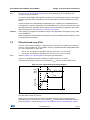
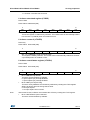
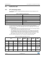
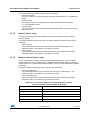
The external interrupt event generates an interrupt if the corresponding configuration is
selected with DDR and OR registers and if the I bit in the CC register is cleared (RIM
instruction).
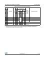
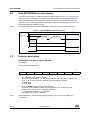
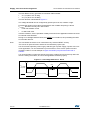
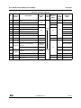
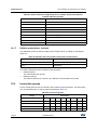
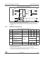
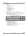
Table 25. I/O port interrupt control/wake-up capability
Interrupt event
External interrupt on selected
external event
10.7
Event flag
Enable
control bit
Exit from
WAIT
Exit from
HALT
-
DDRx
ORx
Yes
Yes
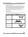
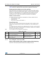
Device-specific I/O port configuration
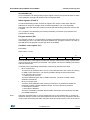
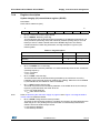
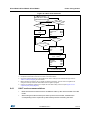
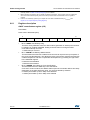
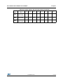
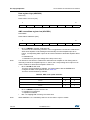
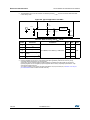
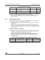
The I/O port register configurations are summarized as follows:
Standard ports
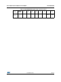
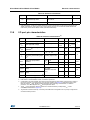
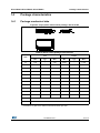
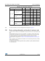
Table 26. Ports PA7:0, PB6:0
Mode
DDR
OR
Floating input
0
0
Pull-up input
0
1
DocID8349 Rev 7
69/170
169