1
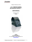
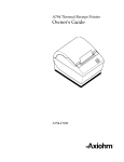
7156 Thermal Receipt and Impact
Slip Printer (RS-232)
Owner's Guide
7156-D100-V001
It is the policy of Axiohm IPB to improve products as new technology, components,
software, and firmware become available. Axiohm IPB, therefore, reserves the right to
change specifications without prior notice.
All features, functions, and operations described herein may not be marketed by Axiohm
IPB in all parts of the world. In some instances, photographs are of equipment prototypes.
Therefore, before using this document, consult your sales representative for information
that is applicable and current.
Copyright © 1995 AXIOHM IPB
Ithaca, New York U.S.A.
All Rights Reserved
Printed in U.S.A.
Confidential, Unpublished
Property of AXIOHM IPB
Axiohm IPB is the name and mark of Dardell Technologies. NCR is the name and mark of
AT&T Global Information Solutions Company. AT&T Global Information Solutions
Company is the name and mark of AT&T. Epson is the name and mark of Seiko Epson
Corporation.
Federal Communications Commission (FCC)
Radio Frequency Interference Statement
Warning
This equipment generates, uses, and can radiate radio frequency energy and if not
installed and used in accordance with the instructions manual, may cause interference to
radio communications. It has been tested and found to comply with the limits for a Class
A computing device pursuant to Subpart J of Part 15 of FCC Rules, which are designed to
provide reasonable protection against such interference when operated in a commercial
environment. Operation of this equipment in a residential area is likely to cause
interference in which case the user at his own expense will be required to take whatever
measures may be required to correct the interference.
Information to User
This equipment must be installed and used in strict accordance with the manufacturer's
instructions. However, there is no guarantee that interference to radio communications
will not occur in a particular commercial installation. If this equipment does cause
interference, which can be determined by turning the equipment off and on, the user is
encouraged to contact Axiohm IPB immediately.
The Axiohm IPB company is not responsible for any radio or television interference
caused by unauthorized modification of this equipment or the substitution or attachment
of connecting cables and equipment other than those specified by Axiohm IPB. The
correction of interferences caused by such unauthorized modification, substitution or
attachment will be the responsibility of the user.
7156 Owner’s Guide
Quick ReferenceAbout the 7156 Printer
Quick Reference
This Quick Reference will direct you to key areas of the Owner's Guide. For a
complete listing of topics, see the Contents or Index.
Ordering Paper and Supplies
page 5
Where to order paper and other supplies.
Setting Up the Printer
page 11
How to set up the printer.
Loading and Changing Paper
page 20
How to change the receipt paper.
Validating and Verifying Checks
page 28
How to validate and verify checks using the optional Magnetic Ink
Character Recognition (MICR) Reader feature.
Testing the Printer
page 30
Directions for running various print tests.
Solving Problems
page 33
How to correct simple problems and get help for serious problems.
Diagnostics
page 41
How to run the diagnostics.
RS-232C Interface
page 62
Specifications for the RS-232C communication interface.
Commands
page 69
Lists and descriptions of the programming commands.
October 1995
i
Quick Reference
7156 Owner’s Guide
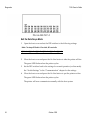
How to Use This Book
Use this book as an installation guide for setting up and preparing the printer to
run, as a training guide for teaching users how to operate the printer, or as a
reference for programming the host system to communicate with the printer. The
book also contains information about the character sets and graphics that are
available. This book describes only RS-232C models of the 7156 printer.
See the Quick Reference, Contents, or Index for finding information.
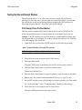
Who Should Use this Book?
This Owner's Guide is intended as a general guide for operators and supervisors
who need to know how to set up and use the printer. It is also intended as a
technical guide for programmers and system integrators who need to know the
technical information about the printer's communication and the programming
commands that control the functions of the printer.
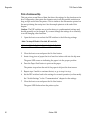
How to Obtain More Information
For more information about the 7156 printer please contact your sales
representative.
For service and disassembly procedures, service training, and parts information,
see the following items (you must be a trained service representative to service
the printer):
•
7156 Thermal Receipt and Impact Slip Printer: Service Guide (7156-D200V001)
•
Field Service Course for 7156 Printer (7156-D400-V001)
•
Parts Information Manual (7156-D300-V001)
For additional copies of the Owner's Guide, contact your sales representative.
ii
October 1995
7156 Owner’s Guide
Contents
Contents
About the 7156 Printer
1
Features and Options...........................................................................................2
Receipt Station...............................................................................................2
Slip Station.....................................................................................................3
Both Stations..................................................................................................3
General Features ...........................................................................................3
Options...........................................................................................................4
Thermal Printhead ...............................................................................................4
Impact Printhead .................................................................................................4
Ordering Paper and Supplies..............................................................................5
Ordering Thermal Receipt Paper.................................................................5
Ordering Ribbon Cassettes...........................................................................8
Ordering Forms.............................................................................................9
Ordering the Power Supply and Cables.................................................... 10
Ordering Cash Drawers ............................................................................. 10
Maintaining and Cleaning the Printer.............................................................. 11
Setting Up and Using the Printer
13
What Is in the Box? ............................................................................................ 13
Removing the Packing Material................................................................. 14
Repacking the Printer ................................................................................. 17
Choosing a Location .......................................................................................... 18
Setting Switches ................................................................................................. 19
Connecting the Cables ....................................................................................... 22
Loading and Changing the Receipt Paper ....................................................... 25
When to Change the Paper......................................................................... 25
Removing the Paper Roll............................................................................ 27
Putting In the Paper Roll ............................................................................ 28
Advancing Paper......................................................................................... 30
October 1995
iii
About the 7156 Printer
7156 Owner’s Guide
Putting In and Changing the Ribbon Cassette ................................................ 31
Removing the Ribbon Cassette .................................................................. 31
Putting In the Ribbon Cassette................................................................... 33
Printing on Forms or Checks ............................................................................ 34
Validating and Verifying Checks ..................................................................... 36
Testing the Printer ............................................................................................. 38
Running the Print Test by Power Cycling the Printer.............................. 38
Running the Print Test by Opening and Closing the Cover.................... 38
Sample Print Test ........................................................................................ 39
Paper Low Sensor .............................................................................................. 40
Solving Problems
33
Printer Beeps Twice........................................................................................... 41
Green LED Does Not Come On/Printer Will Not Print ................................ 42
Red LED Flashes................................................................................................ 42
Red LED Is Constant ......................................................................................... 43
Slip or Forms Printing is Light ......................................................................... 44
Receipt Printing is Light or Spotty ................................................................... 44
LED (Slip Table) Does Not Come On .............................................................. 45
Forms Skew or Catch ........................................................................................ 45
MICR Not Reading Properly ............................................................................ 46
Other Serious Problems..................................................................................... 46
Contacting a Service Representative................................................................ 47
Diagnostics
41
Level 0 Diagnostics............................................................................................ 50
Level 1 Diagnostics............................................................................................ 51
Setting Partial Cut Distance ....................................................................... 53
Setting Data Error and Data Buffer Options ............................................ 54
Ignoring/Using the Carriage Return......................................................... 55
Checking and Adjusting the MICR Reader .............................................. 56
Verifying Read of MICR Characters.......................................................... 60
Running the Data Scope Mode .................................................................. 61
Testing the Slip and Receipt Stations ........................................................ 63
Level 2 Diagnostics............................................................................................ 66
Level 3 Diagnostics............................................................................................ 66
iv
October 1995
7156 Owner’s Guide
Contents
Print Test ............................................................................................................ 66
Running the Print Test by Power Cycling the Printer.............................. 67
Running the Print Test by Opening and Closing the Cover .................... 67
Sample Print Test ........................................................................................ 68
Communication
61
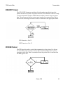
Communication Overview................................................................................ 69
Interface ....................................................................................................... 69
Sending Commands.................................................................................... 69
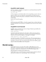
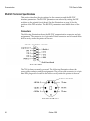
RS-232C Interface............................................................................................... 70
XON/XOFF Protocol .................................................................................. 71
DTR/DSR Protocol ..................................................................................... 71
RS-232C Technical Specifications............................................................... 72
Setting Extra RS-232C Options .................................................................. 76
Commands
69
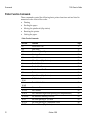
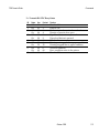
Command List.................................................................................................... 77
Printer Function Commands...................................................................... 78
Print Characteristics Commands ............................................................... 81
Station Select Commands........................................................................... 82
Graphics Commands .................................................................................. 82
Printer Status Commands .......................................................................... 84
Real Time Commands ................................................................................ 84
Bar Code Commands.................................................................................. 85
MICR Reader Commands .......................................................................... 85
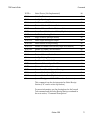
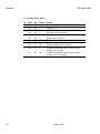
Command Descriptions..................................................................................... 88
Printer Function Commands...................................................................... 88
Print Characteristics Commands ............................................................. 104
Station Select Commands......................................................................... 112
Graphics Commands ................................................................................ 114
Printer Status Commands ........................................................................ 119
Real Time Commands .............................................................................. 121
Bar Code Commands................................................................................ 132
MICR Reader Commands ........................................................................ 135
MICR Parsing ............................................................................................ 136
October 1995
v
About the 7156 Printer
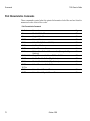
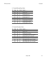
Appendix A: Specifications
7156 Owner’s Guide
147
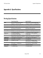
Printing Specifications..................................................................................... 147
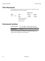
Power Requirements ....................................................................................... 148
Environmental Conditions.............................................................................. 148
Reliability.......................................................................................................... 149
Dimensions and Weight.................................................................................. 149
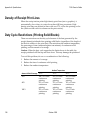
Density of Receipt Print Lines ........................................................................ 150
Duty Cycle Restrictions (Printing Solid Blocks)............................................ 150
Appendix B: Print Characteristics
151
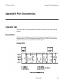
Character Size .................................................................................................. 151
Receipt Station........................................................................................... 151
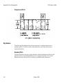
Slip Station................................................................................................. 153
Print Zones ....................................................................................................... 157
Receipt Station........................................................................................... 157
Slip Station................................................................................................. 158
Character Sets .................................................................................................. 159
Index ................................................................................................................. 163
vi
October 1995
7156 Owner’s Guide
About the 7156 Printer
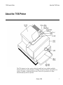
About the 7156 Printer
The 7156 printer is a fast, quiet, relatively small and very reliable multiple
function printer. It prints receipts, validates and prints checks, and prints on a
variety of single- or multiple-part forms. There is no journal as it is kept
electronically by the host system.
October 1995
1
About the 7156 Printer
7156 Owner’s Guide
The industry-standard RS-232C communication interface allows the 7156 to be
connected to any host PC or terminal system that uses RS-232C. Control codes
are provided for easy migration of applications written for Epson as well as other
Axiohm printers.
With thermal printing technology on the more frequently used receipt station,
there is no ribbon cassette to change and paper loading is extremely simple.
Printing on single- or multiple-part forms, validating checks, and printing checks
is also easy in the accommodating slip station. An extra nice option is the
Magnetic Ink Character Recognition (MICR) Reader with parsing which reads
account numbers on checks for easy verification.
Features and Options
The 7156 printer comes with several features and options.
Receipt Station
2
•
Thermal printing
•
Standard pitch (host selectable): 15.2 characters per inch, 44 columns
•
Compressed pitch (host selectable): 19.0 characters per inch, 56 columns
•
Resident bar codes
• Code 39
• Code 128
• UPC-A
• UPC-E
• JAN8 (EAN)
• JAN13 (EAN)
• Interleaved 2 of 5
• Codabar
•
Drop-in paper loading requiring no spindle or threading paper
•
Paper low indicator
(not available on 30XX models; see the model number on the machine label
on the right side of the printer)
•
Paper exhaust
•
Cover open
October 1995
7156 Owner’s Guide
About the 7156 Printer
Slip Station
•
Bi-directional, impact printing
•
Standard pitch (host selectable): 13.9 characters per inch, 66 columns
•
Compressed pitch (host selectable: 17.1 characters per inch, 80 columns
•
Printing of forms up to five plies
• Front insertion of forms with forms stop Testing one two three four five
six seven
• Side insertion of forms with override of forms stop
• Automatic and manual insertion of forms
•
Form alignment sensors
•
Horizontal slip table with optional extension (standard with MICR option)
•
Cover open
•
Variety of print modes: double high (receipt station only), double strike (slip
station only), double wide, upside down, and rotated
•
Two resident character sets:
• PC Code Page 437 (US)
• PC Code Page 850 (Multilingual)
•
16K RAM available for downloadable character sets or bit-mapped graphics
(printing logos)
•
Industry standard RS-232C communication interface
•
History EEROM for custom settings
•
Remote power supply
•
Power and communication support for a remote 2x20 pass-through display
•
Two cash drawer kickouts
•
Audible tone (controlled by application)
Both Stations
General Features
Note: The 7156 does not use a paper journal. The journal is kept electronically by
the host system.
October 1995
3
About the 7156 Printer
7156 Owner’s Guide
Options
•
Magnetic Ink Character Recognition (MICR) Reader built into the slip station
for verifying checks
•
Custom MICR field parsing
•
Extended slip table for handling large forms (standard with MICR)
•
Paper cutter (receipt station)
Thermal Printhead
The 7156 uses a thermal printhead (on the receipt station) for printing receipts,
and it is extremely fast and quiet. Since it uses heat to print directly on paper,
there is no cassette or ribbon to change, eliminating soiled fingers and paper dust.
There is no regularly scheduled maintenance for the printhead and it does not
need to be regularly cleaned. However, if it does appear dirty, wipe it with cotton
swabs and rubbing alcohol. If spotty or light printing problems persist after
cleaning the printhead, contact a service representative. See “Contacting a Service
Representative” in “Solving Problems” later in this book.
Note: The thermal printhead does not normally require cleaning if the
recommended paper grades are used. If non-recommended paper has been used
for an extended period of time, cleaning the printhead with cotton swabs and
rubbing alcohol will not be of much benefit. See “Recommended Suppliers” on
the next page for the recommended paper grades.
The printhead is designed for a very long life, but it may be replaced if needed.
Only a trained service representative may replace the printhead. See “Solving
Problems” to determine if the printhead needs to be replaced.
Impact Printhead
The bi-directional, impact printhead is designed for a very long life, but it may be
replaced if needed. Only a trained service technician may replace the impact
printhead. See “Solving Problems” later in this book to determine if the printhead
needs to be replaced.
4
October 1995
7156 Owner’s Guide
About the 7156 Printer
Ordering Paper and Supplies
Thermal receipt paper, ribbon cassettes, and forms can be ordered from several
recommended and qualified suppliers.
Ordering Thermal Receipt Paper
The 7156 requires “fax grade” thermal paper with the following dimensions:
•
Diameter: 80 mm maximum (3.15 in.)
•
Length: 83 meters (273 ft.)
•
Width: 80 mm +/- .5 mm (3.15 +/- .008 in.)
The paper must not be attached at the core. Otherwise the receipt station will be
damaged when the paper is exhausted.
The paper low LED will blink when there are about 4 1/2 meters (15 feet) of
paper left. If the paper runs out, the paper low LED stays on and the printer stops
printing.
Note: The paper low feature is not available on 30XX models. See the model
number on the machine label on the right side of the printer.
The host system will alert you that the paper in the receipt station is out
(depending on the application program running in the host system).
Recommended Suppliers for Thermal Receipt Paper
The grades of paper listed here will give the best print quality. When more than
one order number is listed, the first number provides better image density. You
may order paper from the following suppliers:
AT&T Global Information Solutions Company
Media Products Division
9995 Washington Church Road
Miamisburg, OH 45342
Voice: 1(800)543-8130 (toll free), or local listing of Media Products sales office
Stock numbers: 878559 (standard density), 856966 (light density)
October 1995
5
About the 7156 Printer
7156 Owner’s Guide
Kanzaki Specialty Papers
Imaging Products
20 Cummings Street
Ware, MA 01082-2002
Voice: 1(413)736-3216, 1(800)628-8386 (toll free)
Fax: 1(413)731-8864
Paper grade: F380 (standard density), F180 (light density)
In Japan:
New OJI Paper Co., LTD
4-7-5 Ginza Chuo-Ku
Tokyo, 104, Japan
Voice: (03)3563-4763
Fax: (03)3563-1136
Paper grade: KF-740-2EX (standard density), KF-740-1EX (light density)
In Germany:
Kanzan Spezialpapiere GMBH
Postlach 101141
Nippessstraße 5
D-5160 Duren, Germany
Voice: 011 49 2421 5924 20
Paper grade: KF-60 (standard density), KF-50 (light density)
Other Qualified Suppliers for Thermal Receipt Paper
The following suppliers sell thermal receipt paper which has been tested with the
7156 and may be used if desired. Contact your supplier for information.
Appleton Papers, Inc.
825-T F Wisconsin Avenue
P. O. Box 359
Appleton, Wisconsin 54912
Voice: 1(414) 734-9841
Paper grade: T1012
6
October 1995
7156 Owner’s Guide
About the 7156 Printer
Arjo-Wiggins Thermal Papers, Ltd.
Whisby Road, North Hykeham
Lincoln, Lincolnshire LN6 9AU
England
Voice: 44 (0) 522 681212
Fax: 44 (0) 522 690972
Paper grade: S552, S662
Nippon Paper Industry Co., Ltd.
Business Communication Paper Division
Shin-Yurakucho Building
1-12-1, Yurakucho, Chiyoda-ku
Tokyo 100 Japan
Voice: 03-3218-8049
Fax: 03-3216-1397
Paper grade: TP50 KS
Ordering Ribbon Cassettes
To order ribbon cassettes, contact your sales representative or order directly from
AT&T Global Information Solutions at the following address or toll free number:
AT&T Global Information Solutions Company
Media Products Division
9995 Washington Church Road
Miamisburg, OH 45342
Voice: 1(800)543-8130 (toll free), or local listing of Media Products sales office
Stock Numbers: 198161 (purple ribbon cassette—3 million characters)
198145 (black ribbon cassette—3 million characters)
October 1995
7
About the 7156 Printer
7156 Owner’s Guide
Ordering Forms
The 7156 prints on single or multiple forms in the slip station (up to five-part
forms). Forms and slips must meet the following requirements:
•
Front insertion (minimum):
51 mm (2.0 in.) wide
70 mm (2.75 in.) long
•
Side insertion (minimum):
203 mm (8.0 in.) wide
51 mm (2.0 in.) long
•
Single-ply forms should be on paper that is greater than 15 pounds
•
Multiple-part forms (up to five parts) should be no thicker than .406 mm (.016
in)
Contact your sales representative to order forms or you may order forms from
AT&T Global Information Solutions at the following address or toll free number:
AT&T Global Information Solutions Company
Media Products Division
9995 Washington Church Road
Miamisburg, OH 45342
Voice: 1(800)543-8130, or local listing of Media Products sales office
8
October 1995
7156 Owner’s Guide
About the 7156 Printer
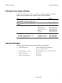
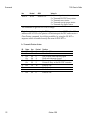
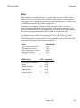
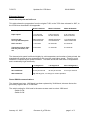
Ordering the Power Supply and Cables
Contact your sales representative to order the supplies listed in the table. The
numbers are for reference only. Suppliers may use other numbers.
Item
Type
Power supply with attached cable to
printer and U.S. power supply cord
Power supply with attached cable to
printer
Power supply cord (to outlet)
Communication cables
RS-232C 25-pin (host) to 9-pin
RS-232C 9-pin to 9-pin
Extended Slip Table
Number
7156-K330-V001
7156-K301-V001
United States
International
United Kingdom
S.E.V.
Australia
7156-K320-V001
7156-K321-V001
7156-K322-V001
7156-K323-V001
7156-K324-V001
(3 meters—9.8 ft.)
(3 meters—9.8 ft.)
1420-C001-0030
1416-C057-0030
7156-K280-V001
Ordering Cash Drawers
The following cash drawers may be used with the 7156 printer:
•
NCR Cash Drawer:
Model 7052-K657 (switchable for
drawer 1 or drawer 2)
•
M-S Cash Drawer Corp.:
Model EP-125 K series, EP 127, EP-102
•
APG Cash Drawer:
Model 322
•
Indiana Cash Drawer:
Model SLD
October 1995
9
About the 7156 Printer
7156 Owner’s Guide
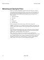
Maintaining and Cleaning the Printer
There is no customer maintenance required for the 7156. However, you may
occasionally clean the cabinet as needed to remove dust and finger marks. Use
any household cleaner designed for plastics, but test it first on a small unseen
area. The cabinet materials and finish are durable and are resistant to the
following items:
•
Cleaning solutions
•
Lubricants
•
Fuels
•
Cooking oils
•
Ultraviolet light
If the receipt paper bucket is dirty, wipe it with a clean, damp cloth.
Caution: Do not spray or try to clean the thermal printhead or the inside of the
printer with any kind of cleaner as this may damage the thermal printhead and
electronics.
If the thermal printhead appears dirty, wipe it with cotton swabs and rubbing
alcohol. If spotty or light printing problems persist after cleaning the thermal
printhead, see “Solving Problems” later in this book.
Note: The thermal printhead does not normally require cleaning if the
recommended paper grades are used. If non-recommended paper has been used
for an extended period of time, cleaning the printhead with cotton swabs and
rubbing alcohol will not be of much benefit. See “Ordering Thermal Receipt
Paper” earlier in this chapter for the recommended paper grades.
10
October 1995
7156 Owner’s Guide
Setting Up and Using the Printer
Setting Up and Using the Printer
What Is in the Box?
The following items are packed in the shipping box:
•
Printer enclosed in a plastic bag and foam pack
• Receipt paper roll, wrapped with a foam strip (inside receipt bucket)
• Test printout protecting the thermal printhead (inside receipt bucket)
• Cardboard support for cantilever (on slip table)
• Foam restraint for carriage (behind front cover)
•
Power supply with cable connecting to printer and power supply cord
connecting to power outlet (these items are included if ordered with the
printer)
•
Ribbon cassette (in box)
•
Installation Report Card
•
Two strain relief bushings for routing cables through the back panel
•
Self-adhesive clip for securing cables under the base
October 1995
11
Setting Up and Using the Printer
7156 Owner’s Guide
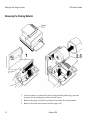
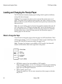
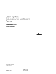
Removing the Packing Material
12
1.
Once the printer is removed from the foam pack and plastic bag, open the
receipt cover by pulling up on the front left corner.
2.
Remove the paper roll and test printout from inside the receipt bucket.
3.
Remove the foam strip from around the paper roll.
October 1995
7156 Owner’s Guide
Setting Up and Using the Printer
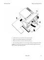
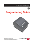
4.
Open the front cover and remove the foam restraint.
5.
Remove the cardboard support from the slip table.
6.
Remove the ribbon cassette and cables from the box.
7.
Save all packing materials for future storing, moving, or shipping the printer.
Caution: Be sure that the foam restraint and the cardboard support have been
removed before operating the printer.
October 1995
13
Setting Up and Using the Printer
7156 Owner’s Guide
Repacking the Printer
1.
Place a piece of receipt paper between the receipt cover and the printhead to
protect the printhead.
2.
Open the front cover and remove the ribbon cassette.
3.
Move the carriage to the right and place the foam restraint between the left
side of the printer and the carriage to protect the carriage.
4.
Place the cardboard support on the slip table.
5.
Place the printer in the plastic bag and foam pack.
6.
Place the packed printer in the box and secure the box with packing tape.
7.
Contact your Axiohm authorized service organization for information on
where to send the printer.
Be prepared to answer questions concerning shipping and billing.
14
October 1995
7156 Owner’s Guide
Setting Up and Using the Printer
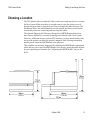
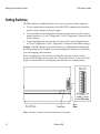
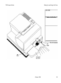
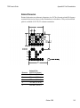
Choosing a Location
The 7156 printer takes up relatively little counter space and may be set on or near
the host system. Make sure there is enough room to open the receipt cover to
change the paper and to open the front cover to change the ribbon cassette. The
illustration shows the actual dimensions of the printer, but leave several inches
around the printer for connecting and accessing the cables.
The optional Magnetic Ink Character Recognition (MICR) Reader feature has
been factory adjusted for a normal operating environment with a host system.
However, additional devices, such as CRT monitors, or large metal surfaces that
are near the printer can affect the printer's magnetic field, causing intermittent
reading errors when the MICR Reader is in operation.
This condition can be easily diagnosed by checking the MICR Reader adjustment
which allows you to reset the MICR Reader if the factory setting has been altered
by your operating environment. See “Adjusting the MICR Reader” later in this
book.
October 1995
15
Setting Up and Using the Printer
7156 Owner’s Guide
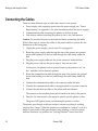
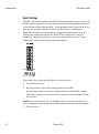
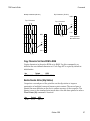
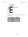
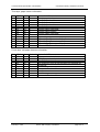
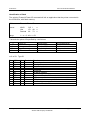
Setting Switches
The DIP switches, located behind the front cover, are used for three purposes:
•
To set communication parameters for the RS-232C communication interface
(see the switch settings on the next page)
•
To set variables for several printer functions (see the sections for the various
printer functions in “Level 1 Diagnostics” in the “Diagnostics” chapter for the
switch settings)
•
To perform diagnostic tests (see the sections for the various diagnostic tests
in “Level 1 Diagnostics” in the “Diagnostics” chapter for the switch settings)
Caution: The DIP switches are set at the factory to predetermined settings and
should generally not be changed. If you must change the settings do so carefully
to avoid changing other functions.
Before changing any of the switches, first run the print test to print out the
current switch settings on the receipt. See “Testing the Printer” at the end of this
chapter for instructions on running the print test and for a sample printout.
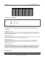
Note: Switch 1 is shown in the Off position for reference.
16
October 1995
7156 Owner’s Guide
Setting Up and Using the Printer
Use a paper clip or other pointed object to set the switches.
1.
Open the front cover.
2.
Set the switches to the desired settings shown in the table.
Switch 1 must be set to Off for the on-line mode. Setting switch 1 to On puts
the printer in level 1 diagnostics (setup mode). Changing the other switches
in level 1 diagnostics can change settings that have been pre-set at the factory.
See “Level 1 Diagnostics” later in this book for more information.
3.
Close the cover.
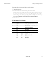
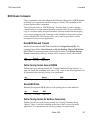
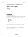
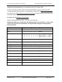
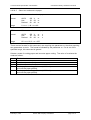
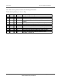
DIP Switch Settings for RS-232C Parameters
Switch
Settings
Description
1
OFF
ON
OFF
ON
OFF
ON
OFF
ON
5
OFF
ON
OFF
ON
On-line Mode (default)
Level 1 Diagnostics (setup mode)
DTR/DSR Protocol (default)
XON/XOFF Protocol
Without Parity (default)
With Parity
Odd Parity
Even Parity
2
3
4
5, 6
6
OFF
OFF
ON
ON
19,200 Baud
9600 Baud (default)
4800 Baud
1200 Baud
October 1995
17
Setting Up and Using the Printer
7156 Owner’s Guide
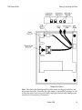
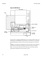
Connecting the Cables
There are three different types of cables that connect to the printer:
•
Power supply cable supplying power from the power supply (see “Power
Requirements” in Appendix A for more information about the power supply)
•
Communication cable connecting the printer to the host system
•
Cash drawer cables connecting the printer to one or two cash drawers
Caution: Be sure that all power is disconnected before connecting the cables.
Follow these steps to connect the cables to the printer and host system. See the
illustration on the facing page.
1.
Unplug the power supply's power cord if it is plugged in.
2.
Route the power supply cable through the rear of the printer (an optional
strain relief bushing is in the box) and through the cable clamp under the
base.
3.
Plug the power supply cable into the power connector under the base.
4.
Plug the power cord into the power supply, then into an outlet.
At this point, the printer receives power. However, the printer is not “online” until the On Line button is pushed.
5.
Route the communication cable through the rear of the printer (an optional
strain relief bushing is in the box) and through the cable clamp under the
base.
6.
Connect the communication cable to the connector under the base.
7.
Connect the communication cable to the appropriate host system connector.
8.
Connect the cash drawer cables to the printer and cash drawers.
The connectors are standard phone jacks located in the back of the printer.
9.
Press the On Line button on the operator panel to put the printer on-line.
The power LED (green) comes on indicating the printer is on-line.
The printer goes through a self-test routine to ensure everything is working
properly then “beeps.” When the printer has completed its “startup” cycle, it is
ready to receive data. If the printer doesn't start printing, or the host system
indicates that there is a problem, see “Solving Problems” later in this book.
18
October 1995
7156 Owner’s Guide
Setting Up and Using the Printer
Note: The strain relief bushings and the cable clamp are shipped in the box and
help secure the cables. Use either the cable clamp or strain relief bushings, or both
to keep the cables from being accidentally unplugged and possibly damaging the
connectors or interrupting a transaction.
October 1995
19
Setting Up and Using the Printer
7156 Owner’s Guide
Loading and Changing the Receipt Paper
The 7156 features extremely simple paper loading which is quick and efficient,
saving both time and paper.
Caution: Do not operate the printer or host system if the printer runs out of
paper. The printer will not operate without paper, but it may continue to accept
data from the host system. Because the printer cannot print any transactions, the
data may be lost.
Note: If you are loading paper for the first time and have already taken the roll
out of the printer, go to “Putting In the Paper Roll” later in this chapter. If you
have not taken the roll out, continue with the following instructions. Although
the illustrations show a used roll being removed, the instructions apply to
loading paper for the first time.
When to Change the Paper
You will need to change the paper when the paper low LED (red) flashes. There
will be approximately 1 1/2 to 7 1/2 meters (5-25 feet) of paper remaining on the
receipt roll. If the LED is turned on steady, the paper is out.
Note: The paper low feature is not available on 30XX models. See the model
number on the machine label on the right side of the printer.
20
•
LED blinks: paper is low (not available on 30XX models)
There are approximately 1 1/2 to 7 1/2 meters (5-25 feet) of paper remaining
on the roll. Change the paper as soon as possible to avoid running out of
paper part way through a transaction.
•
LED on steady: paper is out
Change the paper now. Do not run a transaction without paper as the data
may be lost.
October 1995
7156 Owner’s Guide
Setting Up and Using the Printer
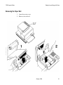
Removing the Paper Roll
1.
Open the receipt cover.
2.
Remove the used roll.
October 1995
21
Setting Up and Using the Printer
7156 Owner’s Guide
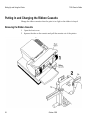
Putting In the Paper Roll
Note: Tear off the end of the new roll so that the edge is loose.
1.
Place the new roll in the bin with a little extra paper extending over the front.
Be sure the paper unrolls from the bottom of the roll. Otherwise the paper
will not be printed on because the thermal coating will be on the wrong side.
22
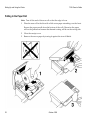
2.
Close the receipt cover.
3.
Remove the excess paper by tearing it against the tear-off blade.
October 1995
7156 Owner’s Guide
Setting Up and Using the Printer
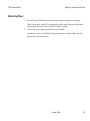
Advancing Paper
1.
Press the Paper Feed button on the operator panel to advance the paper.
The cover must be closed. To ensure print quality and the proper alignment
of the paper, advance about 30 cm (12 inches) of paper.
2.
Tear off the excess paper against the tear-off blade.
In addition to the tear off-blade, some printers have a knife which cuts the
receipt after each transaction.
October 1995
23
Setting Up and Using the Printer
7156 Owner’s Guide
Putting In and Changing the Ribbon Cassette
Change the ribbon cassette when the print is too light or the ribbon is frayed.
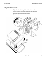
Removing the Ribbon Cassette
24
1.
Open the front cover.
2.
Squeeze the tabs on the cassette and pull the cassette out of the printer.
October 1995
7156 Owner’s Guide
Setting Up and Using the Printer
Putting In the Ribbon Cassette
1.
Tighten the ribbon by turning the knob in the direction of the arrow.
2.
Position the ribbon cassette on the carriage and snap it into place.
Be sure the ribbon is underneath the printhead.
3.
Close the front cover.
October 1995
25
Setting Up and Using the Printer
7156 Owner’s Guide
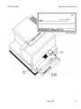
Printing on Forms or Checks
There are several types of transactions that require you to insert a form or check
into the printer:
•
Credit card transaction (some credit card transactions may be printed on the
receipt station and not require any forms)
•
Multiple-part forms such as credit transactions or merchandise returns
•
Electronic funds transfers
•
Check printing (printing the date, payee, and amount on the check face)
Although the illustration on the facing page shows a check being inserted into the
printer, the instructions apply to any type of form. The 7156 can print on forms
up to five-parts thick. See “Ordering Forms” earlier in this book for more
information about the type of forms that can be used.
1.
Insert the form or check (check shown in the illustration) from the front and
place it on the slip table top first and with the print side up.
If the form is extra long, you may need to insert it from the side.
2.
Slide the form or check to the right until it lines up against the guide (wall).
If the form is extra long, you may need to slide it over the form stop to
disengage it. In this case, you will need to mark the slip table for lining up the
form for the proper placement of the print on the form.
3.
Slide the form or check toward the back of the printer until it contacts the
form stop (it won't be able to go any further);
Or, align the form or check with any preset mark you may have made on the
slip table for custom forms.
The green LED on the slip table turns on when the form or check is properly
inserted (it has to cover two sensors on the slip table).
4.
Follow the instructions from the host system.
The printer begins printing.
26
5.
Remove the form or check after it has been fed back out.
6.
Follow the instructions from the host system to finish the transaction.
October 1995
7156 Owner’s Guide
Setting Up and Using the Printer
October 1995
27
Setting Up and Using the Printer
7156 Owner’s Guide
Validating and Verifying Checks
Note: If the MICR Reader feature is present, checks are verified then validated.
1.
Insert the check from the front and place it on the slip table face down as
shown in the illustration.
2.
Slide the check to the right until it lines up against the guide (wall).
3.
Slide the check toward the back of the printer until it contacts the form stop
(it won't be able to go any further);
Or, align the check with any preset mark you may have made on the slip
table.
The green LED on the slip table turns on when the form or check is properly
inserted (it has to cover two sensors on the slip table).
4.
Follow the instructions from the host system.
If the MICR Reader feature is present, the check is fed in and out while the
check numbers are read. If the check is verified as good, it is then validated.
If the check is not verified as good, it is not validated.
Note: Do not hold or keep the check from moving during the MICR Reader
transaction or the check numbers will not be read accurately.
28
5.
Remove the check after it has been fed all the way back out.
6.
Follow the instructions from the host system to finish the transaction.
October 1995
7156 Owner’s Guide
Setting Up and Using the Printer
October 1995
29
Setting Up and Using the Printer
7156 Owner’s Guide
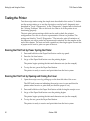
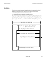
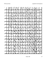
Testing the Printer
Test the receipt station using the simple tests described in this section. To further
test the receipt station or to test the slip station, run the level 1 diagnostic tests
described in “Level 1 Diagnostics” in the “Diagnostics” chapter later in this book.
See “Solving Problems” later in this book for what to do if the printer is not
functioning properly.
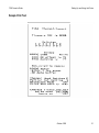
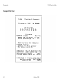
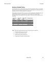
The tests print various settings which can be used to check the printer's
configuration. Give this to a service representative if there is a problem. The
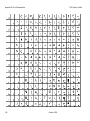
settings are listed in “Level 1 Diagnostics.” The tests also print all variations of
the character set with a partial cut between each variation. See the samples at the
end of this chapter. The tests end with a partial cut, then begin again. Several feet
of paper can be used to print one pass of the test.
Running the Print Test by Power Cycling the Printer
1.
Press and hold down the Paper Feed button on the top panel.
2.
Press the On Line button.
3.
Let go of the Paper Feed button once the printing begins.
The printer begins printing the data and character sets (see the sample).
4.
To stop the test, press the Paper Feed button.
The printer is ready to receive and print data from the host system.
Running the Print Test by Opening and Closing the Cover
1.
Open the receipt cover by pulling up on the front left side of the cover.
The LED (red) comes on indicating the receipt cover is open and that the
printer cannot receive or print data (not that the paper is out).
2.
Press and hold down the Paper Feed button while closing the receipt cover.
3.
Let go of the Paper Feed button once the printing begins.
The printer begins printing the data and character sets (see the sample).
4.
To stop the test, press the Paper Feed button.
The printer is ready to receive and print data from the host system.
30
October 1995
7156 Owner’s Guide
Setting Up and Using the Printer
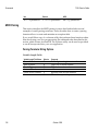
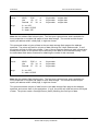
Sample Print Test
October 1995
31
Setting Up and Using the Printer
7156 Owner’s Guide
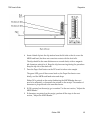
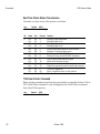
Paper Low Sensor
Note: The paper low sensor is not available on 30XX models. See the model
number on the machine label on the right side of the printer.
The paper low sensor is set at the factory to detect when there are about 4 1/2
meters, +/- 3 meters (15 feet, +/- 10 feet), of receipt paper remaining. The sensor
is adjustable to detect less or more paper remaining. It is recommended,
however, that the sensor be kept at the factory setting.
If the sensor has accidentally been changed, follow these steps to re-adjust it.
These steps will only get the sensor to an approximate position of the factory
setting. To have the sensor reset to the exact setting as the factory setting, a
service representative will need to be called. See “Contacting a Service
Representative” later in this book.
1.
Open the receipt cover.
2.
Move the sensor along the cutout until it is as close as you can get it to the
middle notch.
The other two notches are used for paper low settings in other printer
configurations and can be ignored.
3.
Close the receipt cover.
Note: Remember, this is only an approximation of the factory setting.
32
October 1995
7156 Owner’s Guide
Solving Problems
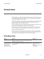
Solving Problems
The 7156 printer is a simple, generally trouble-free printer, but from time to time
minor problems may occur. For example, the power supply may be interrupted
or the thermal printhead may overheat.
A red LED on the operator panel signals that something may be wrong. The light
on the front right side of the printer is used only to indicate when a form is
inserted properly. It does not indicate an error.
For some problems, the printer communicates the information to the host system
and relies on the application to indicate what the problem is.
The information on the following pages describes some problems that you may
encounter: problems that you can easily fix, and others that you will need to
contact a service representative for.
You may be able to correct many of the conditions or problems without calling
for service. However, if a problem persists, contact a service representative. See
“Contacting a Service Representative” at the end of this chapter.
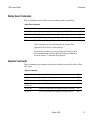
Printer Beeps Twice
Problem
What to Do
Printer Beeps
Twice at Power On
If printer beeps twice during level 0 diagnostics, it
indicates that default values have been loaded into the
EEROM. No action is necessary.
The PC Board needs to be replaced. Contact a service
representative.
If the printer beeps
twice at every
power on, the
EEROM has failed
Where to Go
October 1995
See “Contacting a
Service
Representative” later in
this chapter.
33
Solving Problems
7156 Owner’s Guide
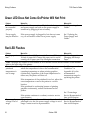
Green LED Does Not Come On/Printer Will Not Print
Problem
What to Do
Where to Go
Cables may not
be connected
properly
Check all cable connections. Check that the host system
and power supply are both on (the power supply is
turned on by plugging it into an outlet).
See “Connecting the
Cables.”
Power supply
may be defective
If the power supply is plugged in, but does not come
on, you will need to order a new power supply.
See “Ordering the
Power Supply and
Cables.”
Red LED Flashes
Problem
What to Do
Where to Go
Receipt paper is
low*
There are about 4 1/2 meters, +/- 3 meters, (15 feet, +/- See “Loading and
10 feet) of paper left. Change the paper soon to avoid
Changing the Receipt
running out of paper part way through a transaction.
Paper.”
*Note: The paper low feature is not available on 30XX models. See the model number on the machine
label on the right side of the printer.
See “Environmental
Thermal
The printhead may overheat when printing in a room
Conditions” in
printhead
where the temperature is above the recommended
Appendix A for the
temperature is
operating temperature or when printing graphics
recommended
out of range
continuously, regardless of the room temperature. In
temperature range for
either case, the printer will shut off.
operating the printer.
If the temperature of the printhead is too hot, adjust the
room temperature or move the printer to a cooler
location.
If the printhead is overheating because of printing
graphics continuously, reduce the demand on the
printer.
See “Contacting a
If the printer continues to overheat, contact a service
Service Representative”
representative.
later in this chapter.
Power supply
If paper is not low and no conditions indicate that the
See “Contacting a
voltage is out of
printhead is too hot, the power supply voltage is out of Service Representative”
range
range. Contact a service representative.
later in this chapter.
34
October 1995
7156 Owner’s Guide
Solving Problems
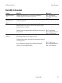
Red LED Is Constant
Problem
What to Do
Where to Go
Receipt paper is
out
Change the paper now. Do not run a transaction
without paper as the data may be lost.
See “Loading and
Changing the Receipt
Paper.”
Receipt cover or
front cover is
open
Knife failure
Close the cover. The printer will not operate with either
of the covers open.
Open the receipt cover and check the knife. Clear any
jammed paper you can see. Tear off any excess paper
against the tear-off blade.
Contact a service representative if this does not resolve
the problem.
Paper jam in slip
station
See “Contacting a
Service Representative”
later in this chapter.
Open the front cover and check the slip table and under
the carriage. Remove any paper you see.
Close the front cover. Press the On Line button twice to
reset the printer.
If you cannot see a paper jam or other obstruction,
contact a service representative.
October 1995
See “Contacting a
Service Representative”
later in this chapter.
35
Solving Problems
7156 Owner’s Guide
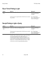
Slip or Forms Printing is Light
Problem
What to Do
Where to Go
Ribbon cassette is
worn
Replace the ribbon the cassette.
See “Putting In and
Changing the Ribbon
Cassette.”
Contact a service representative if this does not resolve
the problem.
See “Contacting a
Service Representative”
later in this chapter.
Receipt Printing is Light or Spotty
Problem
What to Do
Where to Go
Thermal
printhead may be
dirty
Open the receipt cover and clean the thermal printhead
with cotton swabs and rubbing alcohol.
See “Putting In and
Changing the Ribbon
Cassette.”
Contact a service representative if this does not resolve
the problem.
See “Contacting a
Service Representative”
later in this chapter.
Note: The thermal printhead does not normally require
cleaning if the recommended paper grades are used. If
non-recommended paper has been used for an
extended period of time, cleaning the printhead with
cotton swabs and rubbing alcohol will not be of much
benefit. See “Ordering Thermal Receipt Paper” earlier
in this book for the recommended paper grades.
36
October 1995
7156 Owner’s Guide
Solving Problems
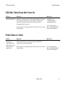
LED (Slip Table) Does Not Come On
Problem
What to Do
Where to Go
Form or check not Line up the form or check against the guide (wall) and
inserted properly slide it toward the back of the printer until it contacts
the form stop and can't go any further. Extra long
forms may need to be inserted from the side to
disengage the form stop.
Contact a service representative if this does not resolve
the problem.
See “Printing on Forms
or Checks” or
“Validating and
Verifying Checks.”
See “Contacting a
Service Representative”
later in this chapter.
Forms Skew or Catch
Problem
What to Do
Form or check
skewing or
catching in slip
station due to an
obstruction or
paper jam
Open the front cover and check for any paper jams or
obvious obstruction in the slip station. Clear the
obstruction or jammed paper.
Where to Go
Contact a service representative if this does not resolve
the problem.
October 1995
See “Contacting a
Service Representative”
later in this chapter.
37
Solving Problems
7156 Owner’s Guide
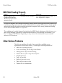
MICR Not Reading Properly
Problem
What to Do
Where to Go
MICR (Magnetic Ink
Character Recognition)
Reader does not read or
misreads checks
Readjust the MICR Reader.
See “Adjusting the MICR Reader” in
the “Diagnostics” chapter.
The optional Magnetic Ink Character Recognition (MICR) Reader feature has been factory adjusted for
a normal operating environment. However, additional devices, such as CRT monitors, or large metal
surfaces that are near the printer can affect the printer's magnetic field, causing intermittent reading
errors when the MICR Reader is in operation.
This condition can be easily diagnosed by checking the MICR Reader adjustment which allows you to
reset the MICR Reader if the factory setting has been altered by your operating environment. If you
have to adjust the MICR Reader frequently, you may want to move the printer away from metal
surfaces or CRT monitors.
Other Serious Problems
The following problems all need to be corrected by a qualified service
representative. See the next section, “Contacting a Service Representative.”
38
•
MICR Not Operating Properly
•
Forms Not Feeding Into the Slip/Forms Printer
•
Missing Dots in Slip or Forms Printing
•
Printer will not cycle or stop when required
•
Illegible characters
•
Paper will not feed
•
Knife will not cycle or cut
•
Platen will not open or close
•
Printer will not communicate
October 1995
7156 Owner’s Guide
Solving Problems
Contacting a Service Representative
For serious problems, such as the printer not printing, not communicating with
the host system, or not turning on, contact your Axiohm authorized service
organization to arrange for a service call.
For self-maintenance organizations, a service guide, parts manual, and self-study
service course are available from Axiohm:
•
7156 Thermal Receipt and Impact Slip Printer: Service Guide (7156-D200V001)
•
Parts Information Manual (7156-D300-V001)
•
Field Service Course for 7156 Printer (7156-D400-V001)
October 1995
39
7156 Owner’s Guide
Diagnostics
Diagnostics
The following diagnostic tests are available for the 7156:
•
Level 0 Diagnostics
Performed during the startup cycle
•
Level 1 Diagnostics (setup mode)
Available in a dedicated environment and accessed through the DIP Switches
•
Level 2 Diagnostics
Performed during normal operation
•
Level 3 Diagnostics
Maintained during normal operation and printed in the print test
•
Print Test
Performed in off-line mode
October 1995
41
Diagnostics
7156 Owner’s Guide
Level 0 Diagnostics
The printer automatically performs level 0 diagnostics when the printer is put online. Level 0 diagnostics comprise the following actions:
•
Motors and solenoids are turned off.
•
Microprocessor timing is checked, CRC check of the firmware ROM is
performed, external RAM is read.
• The green LED on the slip table flashes once if this action succeeds.
• Level 0 diagnostics stop if this action fails. Failure is indicated by the
printer going dead: knife and printhead do not home, the platen does not
open, LEDs are not lit, the printer is unable to communicate with the
host.
•
Knife is homed. A fault condition is caused if this action fails.
•
Slip platen is opened.
•
Slip printhead is homed. A fault condition is caused if this action fails.
•
The status of all sensors is checked, and the status bytes are updated.
If the printer has not been turned on before, or a new EEROM has been installed,
the default values for the printer functions will be loaded into the EEROM during
level 0 diagnostics, This action will be signaled by two beeps. These values can be
changed in level 1 diagnostics. See “Level 1 Diagnostics” for the functions and
their settings.
If the printer continues to beep twice each time it is turned on, it is an indication
that the EEROM has failed.
When the last step is complete, the Paper Feed button is enabled and the printer
is ready for normal operation. Information about the tests is available to the
communication interface through the commands.
42
October 1995
7156 Owner’s Guide
Diagnostics
Level 1 Diagnostics
Level 1 diagnostics (setup mode) allow you to change the settings for various
printer functions and to run certain tests using the DIP switches.
Keep the following information in mind when changing the settings:
•
The settings can only be changed when the printer is in level 1 diagnostics
(setup mode): Switch 1 must be set to On. “Verifying Read of MICR
Characters” is an exception as it is run in on-line mode (switch 1 set to Off).
•
After the switches have been changed, press the on-line button and wait for
the green LED to flash. This does not always apply. See the section for each
function and test for specific instructions.
•
The default options are set at the factory and are stored in the history
EEROM.
•
Once the settings have been changed and stored in the EEROM, the DIP
switches must be set back to the on-line settings for the printer to operate.
•
The stored settings for the functions are printed with a dump of all resident
characters during a print test. See “Print Test” later in this chapter.
Caution: If you are changing the switch settings, be sure they are the correct
settings for that particular function or test to avoid accidentally changing the
settings for another function or test. If the settings are accidentally changed, use
the switch settings shown in the tables throughout this section to change those
settings back. If you need assistance, contact a service representative. See
“Contacting a Service Representative” earlier in this book.
The functions and tests are described in the following order in this section:
•
Setting printhead resistance
•
Setting partial cut distance
•
Setting Data Error and Data Buffer Options
•
Ignoring/using the carriage return
•
Checking and Adjusting the MICR Reader
•
Verifying Read of MICR characters
•
Running the data scope mode
•
Testing the slip and receipt stations
October 1995
43
Diagnostics
7156 Owner’s Guide
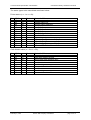
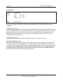
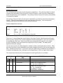
Setting Printhead Resistance
This function changes the setting for the thermal printhead resistance. The setting
must match the letter (A-H) stamped on the heatsink in back of the printhead,
visible by removing the top cover of the printer. Please see the 7156 Service Guide
for information on removing the top cover. This procedure should only be
performed by a trained service representative.
Caution: The DIP switches are set at the factory to predetermined settings and
should generally not be changed. If you must change the settings do so carefully
to avoid changing other functions. Run the print test to see what the current
setting for this function is. See “Print Test” later in this chapter.
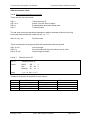
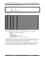
1.
Open the front cover and set the DIP switches to the setting shown in the
table that matches the letter stamped on the heatsink in back of the printhead.
Switch 7 is always Off. Switch 8: On = knife, Off = non-knife
Switch 1
Switch 2
Switch 3
Switch 4
Switch 5
Switch 6
Printhead Setting
On
On
On
On
On
On
On
On
On
On
On
On
On
On
On
On
On
On
On
On
On
On
On
On
Off
Off
Off
Off
On
On
On
On
Off
Off
On
On
Off
Off
On
On
Off
On
Off
On
Off
On
Off
On
A
B
C
D
E
F
G
H
2.
Close the front cover and press the On Line button.
The green LED flashes when the printer cycles.
3.
Set the DIP switches back to the settings for normal operation (on-line mode).
See “Switch Settings” in the “Communication” chapter for the settings.
4.
Close the front cover and press the On Line button.
The green LED flashes when the printer cycles.
44
October 1995
7156 Owner’s Guide
Diagnostics
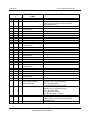
Setting Partial Cut Distance
This function changes the length of the partial knife cut: the higher the number,
the longer the cut.
Caution: The DIP switches are set at the factory to predetermined settings and
should generally not be changed. If you must change the settings do so carefully
to avoid changing other functions. Run the print test to see what the current
setting for this function is. See “Print Test” later in this chapter.
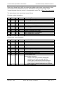
1.
Open the front cover and set the DIP switches to the setting in the table that
matches the value you want for the length of the cut.
Switch 7 is always Off. Switch 8: On = knife, Off = non-knife
Switch 1
Switch 2
Switch 3
Switch 4
Switch 5
Switch 6
Value for Length of
Knife Cut
On
On
On
On
On
On
On
On
On
On
On
On
On
On
On
On
Off
Off
Off
Off
Off
Off
Off
Off
Off
Off
Off
Off
On
On
On
On
Off
Off
On
On
Off
Off
On
On
Off
On
Off
On
Off
On
Off
On
0
1
2
3
4
5 (Default)
6
7
2.
Close the front cover and press the On Line button.
The green LED flashes when the printer cycles.
3.
Set the DIP switches back to the settings for normal operation (on-line mode).
See “Switch Settings” in the “Communication” chapter for the settings.
4.
Close the front cover and press the On Line button.
The green LED flashes when the printer cycles.
October 1995
45
Diagnostics
7156 Owner’s Guide
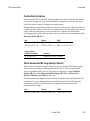
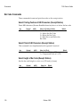
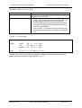
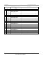
Setting Data Error and Data Buffer Options
This function allows you to select the handling of data reception errors and to
select the size of the data buffer.
Caution: The DIP switches are set at the factory to predetermined settings and
should generally not be changed. If you must change the settings do so carefully
to avoid changing other functions. Run the print test to see what the current
settings for these options are. See “Print Test” later in this chapter.
1.
Open the front cover and note what the current DIP switch settings are.
2.
Set the DIP switches to the settings in the table you want for data reception
errors and the data buffer.
Switch 7 is always Off. Switch 8: On = knife, Off = non-knife
Switch 1
Switch 2
Switch 3
Switch 4
Switch 5
Switch 6
On
Off
On
Off
Off
Off
Option
Print “?” for Data
Errors (Default)
On
Off
On
Off
Off
On
Ignore Data Errors
On
Off
On
Off
On
Off
Set Data Buffer =
4K Bytes (Default)
On
Off
On
Off
On
On
Set Data Buffer =
One Line
Choose one of the Data Errors options and one of the Data Buffer options.
Other possible settings are not used.
3.
Close the front cover and press the On Line button.
The green LED flashes when the printer cycles.
4.
Set the DIP switches back to the settings for normal operation (on-line mode).
See “Switch Settings” in the “Communication” chapter for the settings.
5.
Close the front cover and press the On Line button.
The green LED flashes when the printer cycles.
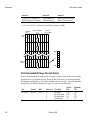
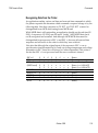
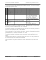
Ignoring/Using the Carriage Return
This function allows the printer to ignore or use the Carriage Return (Hex 0D)
command depending on the application. Some applications expect the command
to be ignored while others use the command as a print command.
46
October 1995
7156 Owner’s Guide
Diagnostics
Caution: The DIP switches are set at the factory to predetermined settings and
should generally not be changed. If you must change the settings do so carefully
to avoid changing other functions.
1.
Open the front cover and set the DIP switches to the settings in the table you
want for ignoring or using the Carriage Return command.
Switch 7 is always Off. Switch 8: On = knife, Off = non-knife
Switch 1
Switch 2
Switch 3
Switch 4
Switch 5
Switch 6
Option
On
On
Off
Off
On
On
On
On
Off
Off
On
Off
Ignore CR (Hex 0D)
Use CR (Hex 0D) as
Print Command
(Default)*
*Emulates the NCR 7150™ printer.
2.
Close the front cover and press the On Line button.
The green LED flashes when the printer cycles.
3.
Set the DIP switches back to the settings for normal operation (on-line mode).
See “Switch Settings” in the “Communication” chapter for the settings.
4.
Close the front cover and press the On Line button.
The green LED flashes when the printer cycles.
October 1995
47
Diagnostics
7156 Owner’s Guide
Checking and Adjusting the MICR Reader
The adjustment procedure described in this section cancels or sharply reduces
extraneous signals picked up by the Magnetic Ink Character Recognition (MICR)
Reader.
Note: The MICR Reader feature has been factory adjusted for a normal operating
environment with a host system. However, additional devices, such as CRT
monitors or large metal surfaces near the printer, can affect the printer's magnetic
field, causing intermittent reading errors when the MICR Reader is in operation.
This condition can be easily diagnosed by checking the MICR Reader adjustment
and readjusting it if the factory setting has been altered. Follow the procedures in
this section to check and adjust the MICR Reader.
Check the MICR Reader Adjustment
Caution: Electro Static Discharge may damage the PC board. Wear a grounded
wrist strap and use a static mat or other ESD protected work surface whenever
you work with the PC board.
1.
Open the front cover.
2.
Press the On Line button to take the printer off-line.
Caution: The DIP switches are set at the factory to predetermined settings and
should generally not be changed. If you must change the settings do so carefully
to avoid changing other functions.
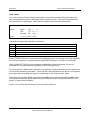
3.
Set the DIP switches to the settings in the table.
See the illustration on the next page for the location of the DIP switches.
Switch 8: On = knife, Off = non-knife
48
Switch 1
Switch 2
Switch 3
Switch 4
Switch 5
Switch 6
Switch 7
On
Off
Off
Off
Off
Off
On
4.
Close the front cover.
5.
Press the On Line button to put the printer back on-line.
October 1995
7156 Owner’s Guide
Diagnostics
6.
Insert a blank slip into the slip station from the left side so that it covers the
MICR read head, but does not come into contact with the feed rolls.
The slip should be the same thickness as a normal check, with no magnetic
ink characters printed on it. Keep the slip from moving during the procedure.
Keep the slip out of the feed rolls.
7.
Press the Paper Feed button on the PC board to take a noise sample.
The green LED goes off then comes back on, the Paper Feed motor runs
briefly, and the MICR read head raises and drops.
Either OK is printed on the receipt (indicating the MICR Reader does not
need to be adjusted), or characters are printed on the receipt. The number of
characters is proportional to the unwanted noise.
8.
If OK is printed on the receipt, go to number 7 in the next section, “Adjust the
MICR Reader.”
9.
If characters are printed on the receipt, perform all the steps in the next
section, “Adjust the MICR Reader.”
October 1995
49
Diagnostics
7156 Owner’s Guide
Adjust the MICR Reader
The procedures to adjust the MICR Reader involve setting the DIP switches and
adjusting the two MICR Reader potentiometers on the PC board. You will need
an insulated flathead screwdriver with a four-inch long shaft and 1/8 inch flat
tip.
Caution: Do not adjust the potentiometers if the green LED is not lit (indicating
the switches are incorrectly set). Doing so causes an incorrect noise sample.
Note: You may need to perform the following steps several times to get the
potentiometers adjusted for the least amount of noise.
50
October 1995
7156 Owner’s Guide
Diagnostics
1.
Remove the front cover from the hinge arm assembly.
This will make it easier to perform the adjustment.
a.
Open the hinge arm assembly.
b. Remove the screws holding the front cover to the hinge arm assembly.
c.
Unsnap the front cover from the hinge arm assembly.
d. Close the hinge arm assembly to finish the adjustment.
2.
Insert a blank slip into the slip station from the left side so that it covers the
MICR read head, but does not come into contact with the feed rolls.
Be sure that the slip covers the MICR read head and stays in position.
3.
Set both potentiometers (on the PC board) to mid range using a screwdriver.
4.
Adjust the lower potentiometer (R9) on the PC board either direction.
The green LED should be on before you adjust the potentiometer.
5.
Press the Paper Feed button on the PC board to take a noise sample.
Repeat steps 3 and 4 until the lowest number of characters is printed. You
may need to adjust the potentiometer both directions to get the best setting.
If OK is printed on the receipt, go to number 7.
6.
Adjust the upper potentiometer (R8) on the PC board either direction.
The green LED should be on before you adjust the potentiometer.
7.
Press the Paper Feed button on the PC board to take a noise sample.
Repeat steps 5 and 6 until the lowest number of characters is printed. Adjust
the potentiometer both directions to get the best setting. When OK is printed,
the noise is low enough for the MICR to operate successfully.
8.
Press the On Line button to take the printer off-line.
9.
Set the DIP switches back to the settings for normal operation (on-line mode).
See “Switch Settings” in the “Communication” chapter for the settings.
10. Reattach the front cover.
11. Close the front cover and press the On Line button to put the printer on-line.
October 1995
51
Diagnostics
7156 Owner’s Guide
Verifying Read of MICR Characters
This test reads the characters on a check and prints a Hex dump of the characters
on the receipt. It is run during normal operation (on-line mode).
Caution: The DIP switches are set at the factory to predetermined settings and
should generally not be changed. If you must change the settings do so carefully
to avoid changing other functions.
1.
Press the On Line button to take the printer off-line.
2.
Set the DIP switches to the settings in the table.
Switch 1 must be set to Off. Switch 8: On = knife, Off = non-knife
Switch 1
Switch 2
Switch 3
Switch 4
Switch 5
Switch 6
Switch 7
Off
On
Off
Off
Off
Off
On
3.
Close the front cover and press the On Line button to put the printer on-line.
4.
Insert a check into the slip station.
The printer waits until a check is inserted. When a check is inserted and
detected, the platen closes and the characters are read by the MICR reader.
The decoded data is printed to the receipt, the platen is opened, and the test
is re-started.
If the MICR reader misreads the characters, question marks “?” are printed
on the receipt. If the MICR reader is unable to read any characters, “NO
MICR CHARACTERS” is printed on the receipt.
5.
Press the On Line button to take the printer off-line and open the front cover.
6.
Set the DIP switches back to the settings for normal operation (on-line mode).
See “Switch Settings” in the “Communication” chapter for the settings.
7.
52
Close the front cover and press the On Line button to put the printer on-line.
October 1995
7156 Owner’s Guide
Diagnostics
Running the Data Scope Mode
This test prints a Hex dump of all data sent to the printer: “1” prints as Hex 31,
“A” as Hex 41 and so on. This helps troubleshoot communication problems, and
runs during a host application (after being enabled in Level 1 Diagnostics).
Enter the Data Scope Mode
Caution: The DIP switches are set at the factory to predetermined settings and
should generally not be changed. If you must change the settings do so carefully
to avoid changing other functions. Run the print test to see if the Data Scope
Mode is on or off. See “Print Test” later in this chapter.
1.
Open the front cover and set the DIP switches to the following settings:
Switch 7 is always Off. Switch 8: On = knife, Off = non-knife
Switch 1
Switch 2
Switch 3
Switch 4
Switch 5
Switch 6
On
Off
Off
On
Off
On
2.
Close the front cover and press the On Line button to take the printer off-line.
The green LED flashes when the printer cycles.
3.
Set the DIP switches back to the settings for normal operation (on-line mode).
See “Switch Settings” in the “Communication” chapter for the settings.
4.
Close the front cover and press the On Line button to put the printer on-line.
The green LED flashes when the printer cycles.
5.
Run a transaction from the host system.
All commands and data sent from the host system will be printed as Hex
characters as shown in the following illustration.
October 1995
53
Diagnostics
7156 Owner’s Guide
Exit the Data Scope Mode
1.
Open the front cover and set the DIP switches to the following settings:
Switch 7 is always Off. Switch 8: On = knife, Off = non-knife
Switch 1
Switch 2
Switch 3
Switch 4
Switch 5
Switch 6
On
Off
Off
On
Off
Off
2.
Close the front cover and press the On Line button to take the printer off-line.
The green LED flashes when the printer cycles.
3.
Set the DIP switches back to the settings for normal operation (on-line mode).
See “Switch Settings” in the “Communication” chapter for the settings.
4.
Close the front cover and press the On Line button to put the printer on-line.
The green LED flashes when the printer cycles.
The printer will now communicate normally with the host system.
54
October 1995
7156 Owner’s Guide
Diagnostics
Testing the Slip and Receipt Stations
These functions allow you to select various tests to check slip and receipt
printing. It is the only way to run the print test on the slip station. You can also
run a print test on the receipt station without changing the DIP switches by
following the procedures in “Print Test” later in this chapter.
Print Sample Check Via Feed Button
This test prints a sample check. Because blank checks are not all laid out the
same, the information may not line up perfectly on the blank check you use.
Caution: The DIP switches are set at the factory to predetermined settings and
should generally not be changed. If you must change the settings do so carefully
to avoid changing other functions.
1.
Open the front cover and set the DIP switches to the following settings:
Switch 7 is always Off. Switch 8: On = knife, Off = non-knife
Switch 1
Switch 2
Switch 3
Switch 4
Switch 5
Switch 6
On
Off
Off
Off
Off
Off
2.
Close the front cover and press the On Line button.
3.
Insert the blank check.
The green LED comes on indicating the check is in the proper position.
4.
Press the Paper Feed button to print the sample check.
The check is fed back out.
5.
Press the Paper Feed button to open the platen so you can remove the check.
6.
Repeat steps 3-5 to print another sample check, or go to step 7 to stop.
7.
Set the DIP switches back to the settings for normal operation (on-line mode).
See “Switch Settings” in the “Communication” chapter for the settings.
8.
Close the front cover and press the On Line button.
The green LED flashes when the printer cycles.
October 1995
55
Diagnostics
7156 Owner’s Guide
Print a Continuous Slip
This test prints several lines of data that show the settings for the functions set in
level 1 diagnostics, then prints the character sets in all the possible variations as
long as slips are fed into the printer. This is similar to the information printed on
the receipt during the receipt test. See the sample printout at the end of this
chapter.
Caution: The DIP switches are set at the factory to predetermined settings and
should generally not be changed. If you must change the settings do so carefully
to avoid changing other functions.
1.
Open the front cover and set the DIP switches to the following settings:
Switch 7 is always Off. Switch 8: On = knife, Off = non-knife
Switch 1
Switch 2
Switch 3
Switch 4
Switch 5
Switch 6
On
Off
Off
Off
Off
On
2.
Close the front cover and press the On Line button.
3.
Insert a long piece of paper that is at least five inches wide into the slip area.
The green LED comes on indicating the paper is in the proper position.
4.
Press the Paper Feed button to print on the paper.
The printer stops when the end of the paper is fed past the front sensor.
5.
Repeat steps 3 and 4 to continue the test, or go to step 6 to stop.
6.
Set the DIP switches back to the settings for normal operation (on-line mode).
See “Switch Settings” in the “Communication” chapter for the settings.
7.
Close the front cover and press the On Line button.
The green LED flashes when the printer cycles.
56
October 1995
7156 Owner’s Guide
Diagnostics
Print a Sample Receipt (Single or Continuous)
These tests print sample receipts, either once or continuously.
Caution: The DIP switches are set at the factory to predetermined settings and
should generally not be changed. If you must change the settings do so carefully
to avoid changing other functions.
1.
Open the front cover and set the DIP switches to the settings in the table for
the test you want to run.
Switch 7 is always Off. Switch 8: On = knife, Off = non-knife
Switch 1
Switch 2
Switch 3
Switch 4
Switch 5
Switch 6
Option
On
Off
Off
Off
On
Off
On
Off
Off
Off
On
On
Sample Receipt Via
Feed Button
Continuous
Sample Receipt
2.
Close the front cover and press the On Line button.
The printer automatically begins printing the sample receipt. If the Sample
Receipt Via Feed Button option is selected, the printer will stop printing after
all the character sets have been printed.
3.
Press the Paper Feed button to repeat the test.
4.
Press the On Line button to stop the test.
5.
Set the DIP switches back to the settings for normal operation (on-line mode).
See “Switch Settings” in the “Communication” chapter for the settings.
6.
Close the front cover and press the On Line button.
The green LED flashes when the printer cycles.
October 1995
57
Diagnostics
7156 Owner’s Guide
Level 2 Diagnostics
Level 2 diagnostics run during normal printer operation. When the following
conditions occur, the printer automatically turns off the appropriate motor,
disables printing to prevent damage, and turns on the red LED (flashes the red
LED if the receipt printhead is too hot or the voltages are out of range):
•
Receipt paper out
•
Receipt cover open
•
Front cover (cassette door) open
•
Receipt knife unable to home
•
Slip carriage motor jam
•
Receipt printhead too hot or voltages out of range (red LED flashes)
See “Solving Problems” earlier in this book for more information about other
conditions that may occur and how to correct them.
Level 3 Diagnostics
Level 3 diagnostics keeps track of the following tallies and prints them on the
receipt during the receipt test. See “Sample Print Test” later in this chapter.
•
Thermal print lines printed
•
Number of knife cuts
•
Number of hours printer is on.
Print Test
Test the receipt station using the simple tests described in this section. To further
test the receipt station or to test the slip station, run the level 1 diagnostic tests
described in “Level 1 Diagnostics” earlier in this chapter.
The tests described here print various settings which can be used to check the
printer's configuration. The settings are listed in “Level 1 Diagnostics.” The tests
also print all variations of the character sets with a partial cut between each
variation. See the sample at the end of this chapter. The sample does not show the
character sets. The tests end with a partial cut, then begin again. Several feet of
paper can be used to print one pass of the test.
58
October 1995
7156 Owner’s Guide
Diagnostics
Running the Print Test by Power Cycling the Printer
1.
Press and hold down the Paper Feed button on the top panel.
2.
Press the On Line button.
3.
Let go of the Paper Feed button once the printing begins.
The printer begins printing the data and character sets (see the sample).
4.
To stop the test, press the Paper Feed button.
The printer is ready to receive and print data from the host system.
Running the Print Test by Opening and Closing the Cover
1.
Open the receipt cover by pulling up on the front left side of the cover.
The LED (red) comes on indicating the receipt cover is open and that the
printer cannot receive or print data (not that the paper is out).
2.
Press and hold down the Paper Feed button while closing the receipt cover.
3.
Let go of the Paper Feed button once the printing begins.
The printer begins printing the data and character sets (see the sample).
4.
To stop the test, press the Paper Feed button.
The printer is ready to receive and print data from the host system.
October 1995
59
Diagnostics
7156 Owner’s Guide
Sample Print Test
60
October 1995
7156 Owner’s Guide
Communication
Communication
Communication Overview
In order for a receipt or slip to be printed, a program must be in place that
translates the data from the host system into a language that the printer can
understand. This program must tell the printer exactly how to print each
character. This chapter describes how to create such a program or modify an
existing one.
Interface
In order for the printer to communicate with the host, a communication link must
be set up. The 7156 supports the industry standard RS-232C communication
interface. This interface has a protocol associated with it that the host system
must understand and adhere to.
Only when the interface parameters are matched and the proper protocol is used
will the host and the printer be able to communicate. See the section, “RS-232C
Interface” on the next page for a description of the protocol associated with the
RS-232C interface.
Sending Commands
Once the communication link is established, commands can be sent to the printer.
This section describes how to send commands to the printer using DOS and
BASIC. This section does not take into account the necessary protocol, but is
meant as a general introduction to how the printer functions.
October 1995
61
Communication
7156 Owner’s Guide
Using DOS to Send Commands
One way of getting commands to the printer is to send them directly from DOS.
For example, the command
COPY CON: COM1:
sets the computer up such that the Hex code corresponding to any key that was
pressed would be sent to the RS-232C communication port COM1 when the
COPY mode is exited. If the printer is connected to COM1, then the data will go
to the printer.
Exit the COPY mode by typing
CTRL Z
and then pressing the ENTER key. Once the computer knows to direct data from
any print command to the proper port, commands can be sent from any software
program.
Using BASIC to Send Commands
In BASIC, printer commands are sent as a string of characters preceded by the
LPRINT command. For example,
LPRINT CHR$(&H0A)
sends the hexadecimal number 0A to the printer, which causes the printer to
print the contents of its print buffer. Previously sent commands tell the printer
exactly how this data should appear on the paper. For example,
LPRINT CHR$(&H12); "ABC"; CHR$(&H0A)
sends the Hex numbers 12 41 42 43 0A to the printer. This causes the printer to
set itself to double wide mode (12), load the print buffer with “ABC” (41 42 43),
and finally, print (0A). Again, the communication link that the BASIC program
outputs to must be matched to that of the printer.
RS-232C Interface
The RS-232C interface uses either XON/XOFF or DTR/DSR protocol. For
XON/XOFF, a particular character is sent back and forth between the host and
the printer to regulate the communication. For DTR/DSR, changes in the
DTR/DSR signal coordinate the information flow.
The RS-232C version of the 7156 offers the standard options which are selected
with the DIP switches. See “Switch Settings” later in this chapter.
62
October 1995
7156 Owner’s Guide
Communication
XON/XOFF Protocol
The XON/XOFF characters coordinate the information transfer between the
printer and the host system. The printer sends an XON character when it is ready
to receive data and it sends an XOFF character when it cannot accept any more
data. The software on the host system must monitor the communication link as
shown in the following flowchart in order to send data at the appropriate times.
XON character = Hex 11.
XOFF character = Hex 13.
DTR/DSR Protocol
The DTR signal is used to control data transmission to the printer. It is driven
low when the printer is ready to recieve data and driven high when it cannot
accept any more data. Data is transmitted from the printer after it confirms that
the DSR signal is low.
October 1995
63
Communication
7156 Owner’s Guide
RS-232C Technical Specifications
This section describes the pin settings for the connectors and the RS-232C
interface parameters. The RS-232C parameters are selected by setting the DIP
switches on the printed circuit board. See the illustration on page 16 for the
position of the DIP switches. The RS-232C parameters must match those of the
host.
Connectors
The following illustration shows the RS-232C communication connector and pin
assignments. The connector is a 9-pin male D-shell connector and is located in the
hollow cavity under the printer at the rear.
The 7156 is always remotely powered. The following illustration shows the
power cable connector and pin assignments. The power cable connector is a 6-pin
mini DIN plug and is located in the hollow cavity under the printer at the rear.
64
October 1995
7156 Owner’s Guide
Communication
The following illustration shows the pin out designation for the cash drawer
connectors. The following table provides the pinout assignments for cash drawers
one and two. The cash drawer connectors are located at the rear of the printer.
Pin Number
Cash Drawer 1 Connector
Cash Drawer 2 Connector
1
2
Frame Ground
Drawer 1 Solenoid
3
4
5
Drawer 1 Status Switch
+24 Volts (to Solenoid +)
Drawer 2 Solenoid (Optional by
jumper: JPR3)
Ground (Status Switch Return)
Frame Ground
Drawer 2 Solenoid (Optional
by jumper: JPR4)
Drawer 2 Status Switch
+24 Volts (to Solenoid +)
Drawer 2 Solenoid
6
October 1995
Ground (Status Switch Return)
65
Communication
7156 Owner’s Guide
Switch Settings
The DIP switches are located on the PC board behind the front cover as shown in
the illustration on page 16. They are used to set the RS-232C parameters as shown
in the following illustration and table. These parameters must match those of the
host system in order for the host system and the printer to communicate.
Note: The switches can also be used for setting other functions and tests. Be
careful when setting the switches for the RS-232C settings that you do not
accidentally change the settings for the other functions and tests. See “Level 1
Diagnostics” earlier in this book for more information.
Use a paper clip or other pointed object to set the switches.
1.
Open the front cover.
2.
Set the switches to the desired settings shown in the table.
Switch 1 must be set to Off when setting switches for the RS-232C settings.
This puts the printer in the on-line mode where it can communicate with the
host system.
Caution: Do not set switch 1 to On. Setting switch 1 to On puts the printer in
level 1 diagnostics (setup mode) where other functions and tests can be changed.
3.
66
Close the cover .
October 1995
7156 Owner’s Guide
Communication
DIP Switch Settings for RS-232C Parameters
Switch
Settings
Description
1
OFF
2
OFF
ON
OFF
ON
OFF
ON
5
OFF
ON
OFF
ON
On-line Mode, Use to set RS-232C
options (default)
DTR/DSR Protocol (default)
XON/XOFF Protocol
Without Parity (default)
With Parity
Odd Parity
Even Parity
3
4
5, 6
6
OFF
OFF
ON
ON
19,200 Baud
9600 Baud (default)
4800 Baud
1200 Baud
Setting Extra RS-232C Options
The following extra options are available for the RS-232C Interface:
•
Data errors
• Print “?” for data errors (default)
• Ignore data errors
•
Data buffer
• Set data buffer = 4K bytes (default)
• Set data buffer = one line
These options are set with the DIP switches in level 1 diagnostics. See “Level 1
Diagnostics” earlier in this book for instructions on setting these options.
October 1995
67
7156 Owner’s Guide
Commands
Commands
The commands control all operations and functions of the 7156 printer, from
selecting the size and placement of characters and graphics on the receipt or slip
to feeding and cutting the paper.
The 7156 commands emulate the NCR 7150™ Multifunction printer, the Epson
TM-T80™ Thermal printer, and the Epson TM-930™ Thermal printer. You may
select from any of the commands to program a host system to communicate with
the 7156 printer.
Some commands listed and described here are not implemented in the 7156 (they
are identified as not implemented). If received, they are ignored and not sent to
the print buffer as data. Non-legal commands are sent to the print buffer as data.
Command List
This section groups the commands according to the following categories:
•
Printer Function Commands
•
Print Characteristics Commands
•
Station Select Commands
•
Graphics Commands
•
Printer Status Commands
•
Real Time Commands
•
Bar Code Commands
•
MICR Reader Commands
Within each group, the commands are listed in numerical order of their Hex
codes. The page number refers to where a complete description of each command
is given in the “Command Descriptions” section which begins on page 77.
October 1995
69
Commands
7156 Owner’s Guide
Printer Function Commands
These commands control the following basic printer functions and are listed in
numerical order of their Hex codes:
•
Printing
•
Feeding the paper
•
Moving the printhead (slip station)
•
Resetting the printer
•
Cutting the paper
Printer Function Commands
70
Hex Code
Command
Page
09
Horizontal Tab
77
0A
Line Feed
77
0C
Print and Eject Slip
78
0D
Carriage Return
78
10
Clear Printer
78
11
Close Form (Slip Station)
79
14 n
Feed n Print Lines
79
15 n
Feed n Dot Rows
79
16 n
Add n Extra Dot Rows
80
17
Print
81
18
Open Form (Slip Station)
81
19
1B 69
1A
1B 6D
1B 07
Full Knife Cut
81
Partial Knife Cut
81
Generate Tone
82
1B 14 n
Set Column
82
1B 20 n
Set Character Right-Side Spacing (Not Implemented)
82
1B 24 etc.
Set Absolute Starting Position
83
1B 32
Set Line Spacing to 1/6 Inch
83
1B 33 n
Set Line Spacing to n Minimum Units
84
1B 3C
Return Home (Slip Station)
84
October 1995
7156 Owner’s Guide
Commands
1B 3D n
Select Device (Not Implemented)
84
1B 40
Initialize Printer
85
1B 43 n
Set Slip Eject Length
85
1B 44 etc.
Set Horizontal Tab Positions
85
1B 4A n
Print and Feed n Minimum Units
86
1B 4B n
Print and Reverse Feed n Minimum Units
86
1B 55 n
Set or Cancel Unidirectional Print (Slip Station)
86
1B 5C etc.
Set Relative Starting Position
87
1B 61 n
Align Positions (Receipt Station)
88
1B 63 33 n
Select Paper-End Signal Output
88
1B 63 34 n
Select Sensors to Stop Printing
88
1B 63 35 n
Enable or Disable Panel Switch (Paper Feed Button)
88
1B 63 36 n
Enable or Disable On-Line Button
89
1B 64 n
Print and Feed n Lines
89
1B 65 n
Print and Reverse Feed n Lines
89
1B 66 m n
Set Slip Waiting Time
89
1B 6A k
Read from Non-Volatile Memory
90
1B 70 etc.
Generate Pulse to Open Cash Drawer
90
1B 73 n etc.
Write to Non-Volatile Memory
90
1B 7A n
Set or Cancel Parallel Journal Printing
91
1D 14 n
Reverse Feed n Lines (Slip Station)
91
1D 15 n
Reverse Feed n Dots (Slip Station)
91
1E
Journal Tab (ignored if 1B 63 30 used to select station)
92
This command can also be interpreted as Select Receipt
Station (if 1C used to select slip station)
For more information, see the descriptions for the Journal
Tab command and the Select Receipt Station command in
the next section, “Command Descriptions.”
October 1995
71
Commands
7156 Owner’s Guide
Print Characteristics Commands
These commands control what the printed information looks like and are listed in
numerical order of their Hex codes.
Print Characteristics Commands
72
Hex Code
Command
Page
12
Double-Wide Characters
92
13
Single-Wide Characters
93
1B 12
Rotated Print
93
1B 16 n
Select Pitch (Column Width)
93
1B 21 m
Set Print Mode
94
1B 25 n
Select Character Set
94
1B 26 etc.
95
1B 3A 0 0 0
Define User-Defined Character Set (Receipt & Slip
Stations)
Copy Character Set From ROM to RAM
1B 47
Enable Double Strike (Slip Station)
97
1B 48
Disable Double Strike (Slip Station)
98
1B 52 n
1B 74 n
1B 56 n
Select Character Code Table
98
Set or Cancel Rotated Print
98
1B 7B n
Set or Cancel Upside-Down Print
98
October 1995
97
7156 Owner’s Guide
Commands
Station Select Commands
These commands control which station incoming data is printed on.
Station Select Commands
Hex Code
Command
Page
1B 63 30 n
Select Receipt or Slip for Printing, Slip for MICR Read
100
1B 63 31 n
Select Receipt or Slip for Setting Line Spacing
100
1C
Select Slip Station
100
1E
Select Receipt Station (if 1C used to select slip station)
101
This command can also be interpreted as Journal Tab
(ignored if 1B 63 used to select station)
For more information, see the descriptions for the Journal
Tab command and the Select Receipt Station command in
the next section, “Command Descriptions.”
Graphics Commands
These commands print graphics data and are listed in numerical order of their
Hex codes.
Graphics Commands
Hex Code
Command
Page
1B 24 etc.
Set Absolute Starting Position
102
1B 2A m etc.
Set Bit Image Mode
103
1B 4C etc.
1B 59 etc.
1D 2A etc
Double-Density Graphics
105
Define Downloaded Bit Image (Receipt Station)
105
1D 2F m
Print Downloaded Bit Image (Receipt Station)
106
October 1995
73
Commands
7156 Owner’s Guide
Printer Status Commands
These commands send printer status information to the host system and are
listed in numerical order of their Hex codes.
Printer Status Commands
Hex Code
Command
Page
1B 75 0
Transmit Cash Drawer Status
107
1B 76
Transmit Printer Status
108
Real Time Commands
These commands correct difficulties with the original version of the 7156 RS-232C
communication interface.
Real Time Commands
74
Hex Code
Command
Page
1D 04 n
Real Time Status Transmission, GS Sequence
111
10 04 n
Real Time Status Transmission, DLE Sequence
112
1D 03 n
Real Time Request to Printer, GS Sequence
116
10 05 n
Real Time Request to Printer, DLE Sequence
116
1D 05
Real Time Printer Status Transmission
118
October 1995
7156 Owner’s Guide
Commands
Bar Code Commands
These commands print bar codes on the receipt station and are listed in
numerical order of their Hex codes. HRI means Human Readable Interface.
Bar Code Commands
Hex Code
Command
Page
1D 48 n
120
1D 68 n
Select Printing Position of HRI Characters (Receipt
Station)
Select Pitch of HRI Characters (Receipt Station—Not
Implemented)
Select Height of Bar Code (Receipt Station)
1D 6B n etc.
Print Bar Code (Receipt Station)
121
1D 6B 49 n
Print Code 128 Bar Code (Receipt Station)
122
1D 77 n
Select Horizontal Size of Bar Code (Receipt Station)
122
1D 66 n
120
120
MICR Reader Commands
These commands control the Magnetic Ink Character Recognition (MICR) Reader,
including how it parses the character strings on checks.
MICR Reader Commands
Hex Code
Command
Page
1B 77 01
Read MICR Data and Transmit
123
1B 77 50
Define Parsing Format, Save in NVRAM
123
1B 77 52
Reread MICR Data
123
1B 77 70
Define Parsing Format, Do Not Save
Permanently
124
October 1995
75
Commands
76
7156 Owner’s Guide
October 1995
7156 Owner’s Guide
Commands
Command Descriptions
This section lists the commands with their Hex, Decimal, and ASCII codes. The
commands are grouped according to the following categories:
•
Printer Function Commands
•
Print Characteristics Commands
•
Station Select Commands
•
Graphics Commands
•
Printer Status Commands
•
Bar Code Commands
•
MICR Reader Commands
Printer Function Commands
These commands control the following basic printer functions:
•
Printing
•
Feeding the paper
•
Moving the printhead (slip station)
•
Resetting the printer
•
Cutting the paper
Horizontal Tab
Moves the print position to the next horizontal tab position set by the command,
Set Horizontal Tab Positions (1B 44 n1 n2 . . . 00). The print position is reset to
column one after each line.
Hex
Decimal
ASCII
09
9
HT
Line Feed
Prints one line from the buffer and feeds paper one line.
Hex
Decimal
ASCII
0A
10
LF
October 1995
77
Commands
7156 Owner’s Guide
Print and Eject Slip
Prints data from the buffer to the slip station and reverses the slip out the front of
the printer until it clears the feed roller. The command is ignored if the receipt
station is the current station. Upon completion, the receipt station is assigned as
the current station.
Hex
Decimal
ASCII
0C
12
FF
Carriage Return
Prints one line from the buffer and feeds paper one line. The printer can be set
through the DIP switches to ignore or use this command. Some applications
expect the command to be ignored while others use it as a print command. See
“Ignoring/Using the Carriage Return” in the “Diagnostics” chapter earlier in this
book.
Hex
Decimal
ASCII
0D
13
CR
Clear Printer
Clears the print line buffer without printing and sets the following configuration:
78
•
Receipt station: selected
•
Line Spacing, Pitch (Print Mode), User-Defined Character Sets: maintained at
current selections (RAM is not affected)
•
Normal mode: Single-Wide, Single-High, Non-Rotated, and Left-Aligned
•
Printing position: column one
•
Error status: clears a fault condition
•
Slip platen: opened
•
Slip printhead: homed
•
Printer: restarted
•
Knife: homed
Hex
Decimal
ASCII
10
16
DLE
October 1995
7156 Owner’s Guide
Commands
Close Form (Slip Station)
Closes the feed roller and platen (forms compensation arm assembly) and retracts
the forms arm stop. If the printer is reset or the Clear (10) is received, the feed
roller and platen are opened.
Hex
Decimal
ASCII
11
17
DC1
Feed n Print Lines
Feeds paper n lines at the current line height without printing.
Hex
Decimal
ASCII
Value of n
14 n
20 n
DC4 n
0-255
Feed n Dot Rows
Feeds paper n dot rows without printing.
Hex
Decimal
ASCII
Value of n
Receipt
Slip
15 n
21 n
NAK n
0-255
n/152 inch
n/72 inch
October 1995
79
Commands
7156 Owner’s Guide
Add n Extra Dot Rows
Adds n extra dot rows to the character height to increase space between print
lines or decrease number of lines per inch.
Hex
Decimal
ASCII
Value of n
Receipt
Slip
16 n
22 n
SYN n
0-12
n/152 inch
Default = 2
n/72 inch
Default = 3
The following table shows the relationship between the number of lines per inch
and each extra dot row added for both the receipt and slip stations:
Receipt Station
80
Slip Station
Extra
Rows
Lines
Per Inch
Dot Rows
Extra
Rows
Lines Per
Inch
Dot Rows
0
8.5
18
0
10.3
7
1
8.0
19
1
9.0
8
2
7.6
20
2
8.0
9
3
7.2
21
3
7.2
10
4
7.0
22
4
6.5
11
5
6.6
23
5
6.0
12
6
6.3
24
6
5.5
13
7
6.1
25
7
5.1
14
8
5.9
26
8
4.8
15
9
5.6
27
9
4.5
16
10
5.4
28
10
4.2
17
11
5.2
29
11
4.0
18
12
5.1
30
12
3.8
19
October 1995
7156 Owner’s Guide
Commands
Print
Prints one line from the buffer and feeds paper one line.
Hex
Decimal
ASCII
17
23
ETB
Open Form (Slip Station)
Opens the feed roller and platen (forms compensation arm assembly) so that a
form may be inserted (default position).
Hex
Decimal
ASCII
18
24
CAN
Full Knife Cut
This command is implemented the same as Partial Knife Cut (1A, 1B 6D). Use
either Hex 19 or Hex 1B 69.
Hex
Decimal
ASCII
19
1B 69
25
27 105
EM
ESC i
Partial Knife Cut
Partially cuts the receipt. The length of the cut can be changed through the DIP
switches. See “Setting Partial Cut Distance” on page 43. The default setting leaves
.20 inches (5 mm) of paper on the left edge. The cut edge is 108 dot rows or .71
inches (18 mm) above the receipt print line. The command is valid only at the
beginning of a line.
Use either Hex 1A or Hex 1B 6D.
Hex
Decimal
ASCII
1A
1B 6D
26
27 109
SUB
ESC m
October 1995
81
Commands
7156 Owner’s Guide
Generate Tone
Activates a short tone.
Hex
Decimal
ASCII
1B 07
27 7
ESC BEL
Set Column
Prints the first character of the next print line in column n. The command is not
valid with Single or Double Density graphics.
Hex
Decimal
ASCII
1B 14 n
27 20 n
ESC DC4 n
Value of n
Receipt (Pitch)
1-44 (Standard)
1-66 (Standard)
1-56 (Compressed)
1-80 (Compressed)
n resets to one after each line is printed.
Set Character Right-Side Spacing
This command is not implemented and is ignored if received.
82
Value of n
Slip (Pitch)
Hex
Decimal
ASCII
1B 20 n
27 32 n
ESC (SPACE) n
October 1995
7156 Owner’s Guide
Commands
Set Absolute Starting Position
Sets the print starting position to the specified number of dots (up to the right
margin) from the beginning of the line. The print starting position is reset to the
first column after each line.
Hex
Decimal
ASCII
1B 24 n1 n2
27 36 n1 n2
ESC $ n1 n2
n = Number of dots to be moved from the
beginning of the line
n1 = Remainder after dividing n by 256
n2 = Integer after dividing n by 256
The values for n1 and n2 are two bytes in low byte, high byte word orientation.
Determine the value of n by multiplying the column for the absolute starting
position by 10 (standard pitch) or 8 (compressed pitch). The example shows how
to calculate column 29 (10 dots per column) as the absolute starting position.
28 x 10 = 280 dots (beginning of column 29)
280/256 = 1, remainder of 24
n1 = 24
n2 = 1
Note: This command is also used in the graphics mode to emulate the Epson LQ950™ dot matrix printer. See “Graphics Commands” later in this chapter for
more information.
Set Line Spacing to 1/6 Inch
Sets the line spacing to 1/6 of an inch (4.25 mm) or 6 lines/inch on the selected
station. The command is not affected by the Print (17) command. At initialization
the receipt is reset to .13 inch (7.6 lines/inch, 2 extra dot rows); the slip is reset to
.14 inch (7.2 lines/inch, 3 extra dot rows).
Hex
Decimal
ASCII
Default: Receipt
Default: Slip
1B 32
27 50
ESC 2
.13 inch (7.6 lines per
inch, 2 extra dot rows)
.14 inch (7.2 lines per
inch, 3 extra dot rows)
October 1995
83
Commands
7156 Owner’s Guide
Set Line Spacing to n Minimum Units
Sets the line spacing on the selected station:
•
Receipt station: n/360 of an inch
•
Slip station: n/144 of an inch (on some models, the command may not affect
the slip station)
The minimum line spacing is 8.5 lines per inch. The line spacing equals the
character height when n is too small.
Hex
Decimal
ASCII
Value of n
Default
Default: Slip
1B 33 n
27 51 n
ESC 3 n
0-255
.13 inch (7.6 lines
per inch, 2 extra
dot rows)
.14 inch (7.2 lines
per inch, 3 extra
dot rows)
Return Home (Slip Station)
Moves the impact printhead to the home position (beginning of line on the left
side). If the printhead is already in the home position, it is not re-homed.
As the 7156 is able to detect carriage motor jams, the printhead does not need to
be homed after each receipt. The Epson TM-930™ homes the printhead after each
receipt because it is unable to detect carriage motor jams.
Hex
Decimal
ASCII
1B 3C
27 60
ESC <
Select Device
This command is not implemented and is ignored if received.
Hex
1B 3D n
84
Decimal
27 61 n
ASCII
Value of n
Default
ESC = n
0 (bit 0), printer not selected
1 (bit 0), printer selected
1
October 1995
7156 Owner’s Guide
Commands
Initialize Printer
Clears the buffer and resets printer to the default settings (startup configuration).
•
Receipt station is selected
•
Normal mode: Single-Wide, Single-High, Non-Rotated, and Left-Aligned
(printing position set to column one)
•
Extra Dot Rows is set to 2 (receipt), and 3 (slip)
•
User-defined characters or logo graphics (from RAM) are cleared
•
Character Set is set to Code Page 437 (default)
•
Character Pitch is reset to 15.2 CPI (receipt default), 13.9 CPI (slip default)
•
Column Width is reset to 44 characters (receipt) and 66 characters (slip)
Hex
Decimal
ASCII
1B 40
27 64
ESC @
Set Slip Eject Length
This command is not implemented and is ignored if received.
Hex
Decimal
ASCII
1B 43 n
27 67 n
ESC C n
Set Horizontal Tab Positions
Sets up to 32 horizontal tab positions n columns from column one, but does not
move the print position. See the Horizontal Tab (09) command.
Set the tab positions in ascending order and put Hex 00 at the end. Hex 1B 44 00
(number of tabs not specified) clears all tab positions. The tab positions remain
unchanged if the character widths are changed after the tabs are set. The default
tab positions are at intervals of eight characters (column 9, column 17, column 25,
and so forth) for normal print.
Hex
Decimal
ASCII
Value of n
Column number
minus one*
n is always less than or equal to the current selected column width.
1B 44 n1 n2...00
27 68 n1 n2...00
ESC D n1 n2...00
October 1995
85
Commands
7156 Owner’s Guide
Print and Feed n Minimum Units
Prints one line from the buffer and feeds the paper n/360 of an inch on the receipt
station or n/144 of an inch on the slip station.
On the receipt station, the line height equals the character height when n is too
small. This does not apply to the slip station. Use n = 0 to print a line without
feeding the paper. This allows the printer to print on the last line of the slip (at .59
inches from the trailing edge) and still retain the slip in the feed rollers for reverse
feeding the paper back out of the slip station.
Hex
Decimal
Value of n
ASCII
0-255
1B 4A n
27 74 n
ESC J n
n is always less than or equal to the current
selected column width.
Print and Reverse Feed n Minimum Units (Slip Station)
Prints one line from the buffer and reverse feeds the paper n/144 of an inch on
the slip station. The receipt station cannot be reverse fed. If the receipt station is
selected, the paper is fed forward n/360 of an inch.
Hex
Decimal
ASCII
Value of n
1B 4B n
27 75 n
ESC K n
0-255
Set or Cancel Unidirectional Print (Slip Station)
Toggles between unidirectional and bidirectional printing on the slip station.
Unidirectional printing reduces column alignment tolerances and provides higher
quality printing. Printing is normally bidirectional because of the faster speed.
86
Hex
Decimal
ASCII
Value of n
Default
1B 55 n
27 85 n
ESC U n
0 = select bidirectional
1 = select unidirectional
0
October 1995
7156 Owner’s Guide
Commands
Set Relative Starting Position
Moves the print starting position the specified number of dots either right (up to
the right margin) or left (up to the left margin) of the current position.
The print starting position is reset to the first column after each line.
Hex
Decimal
ASCII
Value of n
1B 5C n1 n2
27 92 n1 n2
ESC \ n1 n2
See Examples Below
To Move the Relative Starting Position Right of the Current Position
n = Number of dots to be moved right of the current position
n1 = Remainder after dividing n by 256
n2 = Integer after dividing n by 256
The values for n1 and n2 are two bytes in low byte, high byte word orientation.
Determine the value of n by multiplying the number of columns to move right of
the current position by 10 (standard pitch) or 8 (compressed pitch). The example
shows how to set the relative position two columns in standard pitch (10 dots per
column) to the right of the current position.
2 x 10 = 20 dots (two columns to be moved right of the current position)
20/256 = 0, remainder of 20
n1 = 20
n2 = 0
To Move the Relative Starting Position Left of the Current Position
n = Number of dots to be moved left of the current position
n1 = Remainder after dividing (65,536-n) by 256
n2 = Integer after dividing (65,536-n) by 256
The values for n1 and n2 are two bytes in low byte, high byte word orientation.
Determine the value of n by multiplying the number of columns to move left of
the current position by 10 (standard pitch) or 8 (compressed pitch). The example
shows how to set the relative position two columns in standard pitch (10 dots per
column) to the left of the current position.
October 1995
87
Commands
7156 Owner’s Guide
Align Positions (Receipt Station)
Specifies the alignment of the characters, graphics, logos, and bar codes on the
receipt station according to the table below. The command is valid only when
input at the beginning of a line.
Hex
Decimal
ASCII
Value of n
Default
1B 61 n
27 97 n
ESC a n
0 = Left Aligned
1 = Center Aligned
2 = Right Aligned
0
Select Paper-End Signal Output
This command is not implemented and is ignored if received. The four bytes of
this command are used for backward compatibility to Epson TM-930™
applications. The RS-232C interface can accept multiple status bits, unlike the
parallel interface (used in the Epson TM-930™).
Hex
Decimal
ASCII
1B 63 33 n
27 99 51 n
ESC c 3 n
Select Sensors to Stop Printing
Determines which sensor stops printing on the respective station. The command
does not affect the paper out sensor on the receipt station which automatically
stops the printer when the paper runs out.
Hex
Decimal
ASCII
Bit (of n)
1B 63 34 n
27 99 52 n
ESC c 4 n
0, 1 = Stop Receipt on Receipt Low
4 = Stop Slip if Trailing Edge Uncovered
5 = Stop Slip if Leading Edge Uncovered
Enable or Disable Panel Switch (Paper Feed Button)
Toggles the paper feed button on and off. Only the lowest bit is used to toggle the
paper feed button. If the last bit is 0, the paper feed button is enabled. If the last
bit is 1, the paper feed button is disabled. Functions that require using the paper
feed button cannot be used when it is disabled with this command.
88
Hex
Decimal
ASCII
Value of n
Default
1B 63 35 n
27 99 53 n
ESC c 5 n
0-255
0
October 1995
7156 Owner’s Guide
Commands
Enable or Disable On-Line Button
This command is not implemented and is ignored if received.
Hex
Decimal
ASCII
1B 63 36 n
27 99 54 n
ESC c 6 n
Print and Feed n Lines
Prints one line from the buffer and feeds paper n lines at the current line height.
Hex
Decimal
ASCII
Value of n
1B 64 n
27 100 n
ESC d n
0-255 (0 interpreted as 1
on the receipt station)
Print and Reverse Feed n Lines
Prints one line from the buffer and reverse feeds the paper n lines on the slip
station. The receipt station cannot be reverse fed. If the receipt station is selected,
the paper is fed forward n lines.
Hex
Decimal
ASCII
Value of n
1B 65 n
27 101 n
ESC e n
0-255
Set Slip Waiting Time
Sets the time (in m minutes) that the printer waits for a slip to be inserted into the
slip station and the time (n x 0.1 seconds) for the printer to close the platen and
start printing once the slip has been inserted. The printer reads that a slip is
inserted when the leading edge and trailing edge sensors are covered. The LED
on the slip table is lit (green) when both sensors are covered.
If a slip is not inserted in the time specified, the receipt station is selected for the
next function. If m = 0, the printer waits forever for a slip to be inserted. The
times set by this command are used only by the command, Select Receipt or Slip
for Printing, Slip for MICR Read (1B 63 30 n), with n set to 04.
Hex
Decimal
ASCII
Value of m
Value of n
1B 66 m n
27 102 m n
ESC f m n
0-255
0-255
October 1995
89
Commands
7156 Owner’s Guide
Read from Non-Volatile Memory
Reads a two-byte word from location k in the history EEROM.
Hex
Decimal
ASCII
Value of k
1B 6A k
27 106 k
ESC j k
0-63
With LCSIO (RS-485), the printer returns the word in response to a subsequent
poll. The word is be appended to the normal three-byte response as shown.
STA1
STA2
ADDR
6A
N1
N2
Generate Pulse to Open Cash Drawer
Outputs a pulse defined by n1 and n2 to open a cash drawer.
Hex
Decimal
ASCII
Value of m
Value of n
1B 70 m n1 n2
27 112 m n1 n2
ESC p m n1 n2
0 = Drawer 1
1 = Drawer 2
0-255
n1 = (Pulse Ontime)
n2 = (Pulse Offtime)
The pulse is measured as 2 ms. x n (1 or 2).
Write to Non-Volatile Memory
Writes two-byte word n1:n2 to location k in history EEROM.
Hex
Decimal
ASCII
Value of n
Value of n
1B 73 n1 n2 k
27 115 n1 n2 k
ESC s n1 n2 k
n1 = First Byte
n2 = Second Byte
16-63*
Locations 00-15 (Hex) are reserved.
90
October 1995
7156 Owner’s Guide
Commands
Set or Cancel Parallel Journal Printing
Because there is no journal station on the 7156, this command is not implemented
and is ignored if received.
Hex
Decimal
ASCII
1B 7A n
27 122 n
ESC z n
Reverse Feed n Lines (Slip Station)
Reverses the paper feed in the slip station by n lines at the current spacing. The
next Character Feed command reverses the paper feed back to the normal feed
direction.
Hex
Decimal
ASCII
Value of n
1D 14 n
29 20 n
GS DC4 n
1-255
Reverse Feed n Dots (Slip Station)
Reverses the paper feed in the slip station by n dots at 1/72 inch (NCR 7150™
command). The next Dot Feed command reverses the paper feed back to the
normal feed direction.
Hex
Decimal
ASCII
Value of n
1D 15 n
29 21 n
GS NAK n
1-255
October 1995
91
Commands
7156 Owner’s Guide
Journal Tab
As there is no journal station on the 7156, this command is ignored as a tab
command. However, it is identical to the Select Receipt Station (1E) command
and is used as indicated under the following conditions:
•
If either the receipt or slip station is selected by Select Receipt or Slip for
Printing or MICR (1B 63 60 n), the command (1E) is ignored
•
If the slip station is selected by Select Slip Station (1C), the command (1E)
selects the receipt station
See “Station Select Commands” later in this chapter for more information.
Hex
Decimal
ASCII
1E
30
RS
Print Characteristics Commands
These commands control what the printed information looks like. They control
which character set is selected, enable you to define your own characters, set the
margins, and allow you to produce graphics.
Double-Wide Characters
Prints double-wide characters. The printer is reset to single-wide mode after a
line has been printed or after the Clear Printer (10) command is received. Doublewide characters may be used in the same line with single-wide characters, but not
in the same line with rotated characters or with single or double-density graphics.
92
Hex
Decimal
ASCII
12
18
DC2
October 1995
7156 Owner’s Guide
Commands
Single-Wide Characters
Prints single-wide characters. Single-wide characters may be used in the same
line with double-wide characters, but not in the same line with rotated
charatcters or with single or double-density graphics.
Hex
Decimal
ASCII
13
19
DC3
Rotated Print
Rotates characters 90 degrees counterclockwise. The command remains in effect
until the printer is reset or the Clear Printer (10) command is received. The
command is valid only when input at the beginning of a line. Rotated print and
non-rotated print characters cannot be used together in the same line. See
“Summary of Rotated Printing” on page 99.
Hex
Decimal
ASCII
1B 12
27 18
ESC DC2
Select Pitch (Column Width)
Selects the character pitch for a print line. This command is valid only when
input at the beginning of a line. Standard and compressed pitches cannot be used
together in the same line. See Appendix A for a description of the character
pitches (print modes).
Hex
Decimal
ASCII
Value of n
Default
1B 16 n
27 22 n
ESC SYN n
0 = Standard Pitch
1 = Compressed Pitch
0
The following table provides the print characteristics for both pitches on the
receipt and slip stations.
Pitch
Receipt
Columns
Receipt
CPI
Slip
Columns
Slip
CPI
Standard
Compressed
44
56
15.2
19.0
66
80
13.9
17.1
Set Print Mode
Selects the print mode: standard, compressed, double high, or double wide. See
Appendix A for a description of the standard and compressed character pitches
(print modes).
October 1995
93
Commands
7156 Owner’s Guide
Hex
Decimal
ASCII
Value of m
Default
1B 21 m
27 33 m
ESC ! m
See Next Table
0
Value of m
Bit
Function
0
1
Bit 01
Pitch
Compressed Pitch
56 Col/Line, 19 CPI (Rec)
80 Col/Line, 17.1 CPI (Slip)
Bit 4
Double
High3
Double
Wide
Standard Pitch2
44 Col/Line, 15 CPI (Rec)
66 Col/Line, 13.9 CPI (Slip)
Canceled
Canceled
Set
Bit 5
Set
1Bit 0 is ignored unless it is at begining of line. Bits 1, 2, 3, 6, 7 are not used.
2Standard and compressed pitch cannot be used together in the same line.
3Double-high characters cannot be used with normal characters in the same
line, nor can they be used on the slip station.
Select Character Set
Selects the character set. The character sets cannot be used together on the same
line. When an undefined RAM character is selected, the Code Page 437 character
is used. See Appendix A for the character sets.
94
Hex
Decimal
ASCII
Value of n
Default
1B 25 n
27 37 n
ESC % n
n = 0: Code Page 437
n = 1: User defined
(RAM character set)
n = 2: Code Page 850
0
October 1995
7156 Owner’s Guide
Commands
Define User-Defined Character Set (Receipt Station)
Defines and enters downloaded characters (for the receipt station) into RAM. It
may be used to overwrite single characters. The user-defined characters are
available until power to the printer is turned off, an Initialize Printer command
(1B 40) is received, or a downloaded bit image (1D 2A) is defined.
User-defined character sets for both slip and receipt may be used at the same
time. The command clears bit image logo data from RAM. See the illustration on
the next page of a sample character cell.
Hex
Decimal
ASCII
1B 26 3 c1 c2 n1 d1 . . .
nn dn
27 38 3 c1 c2 n1 d1 . . .
nn dn
ESC & 3 c1 c2 n1 d1 . . .
nn dn
c = the ASCII codes of the first (c1) and last (c2) characters respectively
c1 = Hex 20-FF (Hex 20 is always printed as a space)
c2 = Hex 20-FF (Hex 20 is always printed as a space)
To define only one character, use the same code for both c1 and c2
n = the number of dot columns for the nth character as specified by n1 . . . nn
n = 1-10 (standard pitch), 12 and less accepted but ignored
n = 1-8 (compressed pitch), 12 and less accepted but ignored
d = the column data for the nth character as specified by d1 . . . dn
The number of bytes for a particular character cell is 3 x n1
The bytes are printed down and across each cell
October 1995
95
Commands
7156 Owner’s Guide
Define User-Defined Character Set (Slip Station)
Defines and enters downloaded characters (for the slip station) into RAM (this
command is both an NCR 7150™ and an Epson TM-T80™ command).
Hex
Decimal
ASCII
1B 26 0 c1 c2 d1 . . . dn
27 38 0 c1 c2 d1 . . . dn
ESC & 0 c1 c2 d1 . . . dn
c = the ASCII codes of the first (c1) and last (c2) characters respectively
c1 = Hex 20-FF (Hex 20 is always printed as a space)
c2 = Hex 20-FF (Hex 20 is always printed as a space)
To define only one character, use the same code for both c1 and c2
d = the column data for the nth character as specified by d1 . . . dn
Each character is defined by 12 bytes (only bytes 2-11 are printed)
Each byte is one 7-dot high column (full- or half-dot column)
Overlapped dots are not printed
The data must contain [(c2 - c1 + 1) x 12] bytes
This command may be used to overwrite single characters. It will clear bit image
data from RAM. The user-defined characters are available until power to the
printer is turned off, an Initialize Printer command (1B 40) is received, or a
downloaded bit image (1D 2A) is defined.
User-defined character sets for both slip and receipt may be used at the same
time. See the illustration below of a sample character cell.
96
October 1995
7156 Owner’s Guide
Commands
Receipt Characters (1B 26 3)
Slip Characters (1B 26 0)
MSB
Top of Character
Top of Character
dn
d1 d4
d1 d4
d
10
LSB
MSB
Least Significant
Bit Is Not Printed
d2 d5
dn
d3
dn
LSB
Copy Character Set from ROM to RAM
Copies characters in the active ROM set to RAM. Use this command to reinitialize the user defined character set. Code Page 437 is copied by default at
initialization.
Hex
Decimal
ASCII
1B 3A 0 0 0
27 58 0 0 0
ESC : 0 0 0
Enable Double Strike (Slip Station)
Overprints a second pass of the print line on the slip station to improve
penetration of multiple forms and increase print contrast. The second pass is
printed the same direction as the first to ensure accuracy of the overprint. The
printer is reset to the standard print mode after a line has been printed or after a
Clear Printer (10) command is received.
Hex
Decimal
ASCII
1B 47
27 71
ESC G
October 1995
97
Commands
7156 Owner’s Guide
Disable Double Strike (Slip Station)
Turns off the double strike mode on the slip station.
Hex
Decimal
ASCII
1B 48
27 72
ESC H
Select Character Code Table
Selects the character set to be used. Code Page 437 and Code Page 850 cannot be
used together on the same line. See Appendix A for both character sets.
Hex
Decimal
ASCII
Value of n
Default
1B 52 n
1B 74 n*
27 82 n
27 116 n*
ESC R n
ESC t n*
0 = Code Page 437
1 = Code Page 850
0
Set or Cancel Rotated Print
Rotates characters 90 degrees clockwise. It remains in effect until the printer is
reset or until a Clear Printer (10) or Rotated Print (1B 12) command is received. It
is valid only at the beginning of a line. Rotated print and non-rotated print cannot
be used together in the same line. See “Summary of Rotated Printing” on the next
page.
Hex
Decimal
ASCII
Value of n
Default
1B 56 n
27 86 n
ESC V n
0 = Cancel
1 = Set
0
Set or Cancel Upside-Down Print
Prints upside-down characters. It is valid only at the beginning of a line. The
character order is inverted in the buffer so text is readable. Upside-down and
right-side up print cannot be used together in the same line. It remains in effect
until the Rotated Print (1B 12) command is received. Only bit 0 is used. Bits 1-7
are not used. See “Summary of Rotated Printing” on the next page.
98
Hex
Decimal
ASCII
Value of n
Default
1B 7B n
27 123 n
ESC { n
0 = Cancel
1 = Set
0
October 1995
7156 Owner’s Guide
Commands
Summary of Rotated Printing
The table shows the combinations of Set/Cancel Upside-Down Print, Set/Cancel
Rotated Print (clockwise), and Rotated Print (counterclockwise). Rotated CCW is
mutually exclusive with the other two commands.
The samples of the print show only the normal size characters. Double-wide and
double-high characters are printed in the same orientation (double-high
characters cannot be printed on the slip station). They may also be mixed on the
same line.
Upside Down
1B 7B n
Rotated CW
1B 56 n
Rotated CCW
1B 12
Resulting Output
Canceled
Canceled
Set
Set
X
Canceled
Set
Canceled
Set
X
Cleared
X
X
X
Set
1 (See Below)
2 (See Below)
3 (See Below)
4 (See Below)
5 (See Below)
Note: The following print modes cannot be mixed on the same line:
• Standard and compressed pitch
• Vertical (normal) and rotated
• Right-side up and upside down
• Single high (normal) and double high
October 1995
99
Commands
7156 Owner’s Guide
Station Select Commands
These commands decide which station any incoming data will be printed on.
Select Receipt or Slip for Printing, Slip for MICR Read
Selects the station for printing. If a slip is present and the station selected changes
from slip to receipt, the slip is ejected. If the station selected changes from receipt
to slip, the printer waits for a slip or check to be inserted, either for printing or for
reading the MICR characters. See Set Slip Waiting Time (1B 66 m n).
As there is no journal station on the 7156, bit 0 and bit 1 both select the receipt
station. In the Epson TM-930™ the command can be used to select the journal
station (bit 0). The command is valid only when input at the beginning of a line.
Hex
Decimal
ASCII
Value of n
1B 63 30 n
27 99 48 n
ESC c 0 n
1, 2, 3 = Receipt
4 = Slip
Select Receipt or Slip for Setting Line Spacing
Selects the station for setting line spacing. As there is no journal station on the
7156, bit 0 and bit 1 both select the receipt station. In the Epson TM-930™ the
command can be used to select the journal station (bit 0).
Hex
Decimal
ASCII
Value of n
1B 63 31 n
27 99 49 n
ESC c 1 n
1, 2, 3 = Receipt
4 = Slip
Select Slip Station
Selects the Slip Station for all functions. The receipt station is the default setting
after the printer is initialized or the Clear Printer (10) command is received. If a
select command for one station is followed by a select for another station with no
data sent for the first station, only the second station will be selected.
100
Hex
Decimal
ASCII
1C
28
FS
October 1995
7156 Owner’s Guide
Commands
Select Receipt Station
Selects the Receipt Station for all functions. The receipt station is the default
setting after the printer is initialized or the Clear Printer (10) command is
received. If a select command for one station is followed by a select for another
station with no data sent for the first station, only the second station will be
selected.
Note: This command is identical to Journal Tab (1E), an Epson TM-930™
command. As there is no journal station on the 7156, this command is ignored as
a tab command. The following conditions occur when this command is used:
•
If either the receipt or slip station is selected by Select Receipt or Slip for
Printing or MICR (1B 63 60 n), the command (1E) is ignored
•
If the slip station is selected by Select Slip Station (1C), the command (1E)
selects the receipt station
See “Printer Function Commands” earlier in this chapter for more information.
Hex
Decimal
ASCII
1E
31
RS
October 1995
101
Commands
7156 Owner’s Guide
Graphics Commands
These commands are used to enter and print graphics data.
Set Absolute Starting Position
Sets the print starting position for graphics on the receipt station at the specified
number of dots from the beginning of the line as expressed in the following
formula: n = ((n1 + (256 x n2)) x 2). The resulting dot column must be less than
448. The print starting position is reset to column one after each line.
This command emulates the Epson LQ-950™ dot matrix printer. This allows the
7156 to accept graphics that are normally output from word processing programs
to a half-dot matrix printer.
Hex
Decimal
ASCII
1B 24 n1 n2
27 36 n1 n2
ESC $ n1 n2
n = Number of half dots to be moved from the beginning of the line
Note: The 7156 converts two half-dots to one full dot
n1 = Remainder after dividing n by 256
n2 = Integer after dividing n by 256
102
October 1995
7156 Owner’s Guide
Commands
Set Bit Image Mode
Sets the print resolution and enters one line of graphics data into the print buffer.
Excess data is accepted but ignored. Any print command is required to print the
data, after which the printer returns to normal processing mode. See the
illustration on the next page for a graphic representation of the bit image.
Hex
Decimal
ASCII
1B 2A m n1 n2 d1...dn
27 58 m n1 n2 d1...dn
ESC : m n1 n2 d1...dn
Receipt Station
Value of m
0
1
32
33
Mode
No. of Dots
(Vertical)
No. of Dots
(Horizontal)
Number of
Dots/LIne
Mode
No. of Dots
(Vertical)
No. of Dots
(Horizontal)
Number of
Dots/LIne
8 Dot Single Density
8 Dot Double Density
24 Dot Single Density
24 Dot Double Density
8 (51 DPI)
8 (51 DPI)
24 (152 DPI)
24 (152 DPI)
224 (76 DPI)
448 (152 DPI)
224 (76 DPI)
448 (152 DPI)
8 x 224
8 x 448
24 x 224
24 x 448
Slip Station
Value of m
0
7 Dot Single Density
7 (72 DPI)
330 (69.5 DPI) 7 x 330
1*
7 Dot Double Density
7 (72 DPI)
660 (139 DPI)
7 x 660
32, 33
Not Available on Slip
In single density, one byte (7 dots) is printed in each full dot column; in double
density, one byte is printed in each half/full dot column.
*Adjacent horizontal dots (overlapping dots) are not printed on the slip.
Value of n (8-Dot
Single-Density Mode)
Value of n (24-Dot
Single-Density Mode)
Value of d
Number of Bytes of Data*
n1 + (256 x n2)
3 x [n1 + (256 x n2)]
*Printed left to right (8-dot mode); Printed down then across (24-dot mode).
October 1995
103
Commands
7156 Owner’s Guide
Single-Density Graphics
This NCR 7150™ command is not available. Use Set Bit Image Mode (1B 2A)
described on the previous page. The Hex code, 1B 4B, is used for an Epson
command, Print and Reverse Feed n Mininimum Units (1B 4B n).
104
October 1995
7156 Owner’s Guide
Commands
Double-Density Graphics
Enters one line of 8-dot double-density graphics into the print buffer. Excess data
is accepted but ignored. Any print command is required to print the data, after
which the printer returns to normal processing mode.
Double-density mode allows 0-448 dot columns on the receipt, 0-660 dot columns
on the slip. The number of bytes sent is represented by the formulas in the second
table. Each bit corresponds to one horizontal dot. Adjacent horizontal dots
(overlapping dots) will not be printed on the slip. Compare this command to Set
Bit Image Mode (1B 2A...).
Hex
Decimal
ASCII
1B 4C n1 n2 d1...dn
1B 59 n1 n2 d1...dn
27 76 n1 n2 d1...dn
27 89 n1 n2 d1...dn
ESC L n1 n2 d1...dn
ESC Y n1 n2 d1...dn
Value of n (8-Dot
Double-Density Mode)
n1 + (256 x n2)
Printed left to right.
Value of d
Number of Bytes of Data*
Define Downloaded Bit Image (Receipt Station)
Enters a downloaded bit image (such as a logo) into 16K of RAM for the receipt
station with the number of dots specified by n1 and n2. The downloaded bit
image is available until power to the printer is turned off, or until Initialize
Printer (1B 40), another Downloaded Bit Image (1D 2A), or Define UserDefined Character Set (1B 26) is received.
The downloaded bit image and user-defined characters cannot be defined at the
same time. Any user-defined characters will be cleared from RAM when this
command is used. See the illustration for a graphic representation of the
downloaded bit image.
Hex
Decimal
ASCII
1D 2A n1 n2 d1...dn
29 42 n1 n2 d1...dn
GS * n1 n2 d1...dn
October 1995
105
Commands
7156 Owner’s Guide
Value of n1
Value of n2
Value of d
Bytes of Data (Printed
1-56 (8 x n1 = Number of 1-48 (Number of
Down Then Across)
Horizontal Dot Columns) Vertical Bytes)*
*The number of bytes sent is represented by the following formula:
n = 8 x n1 x n2 (n1 x n2 must be less than or equal to 1344).
Column
Top of Graphic
One
Column
56 x 8 Max.
Row
One d1 d
49
d2
MSB
dn
Row 48 d
Max. 48
dn
LSB
Print Downloaded Bit Image (Receipt Station)
Prints a downloaded bit image (such as a logo) on the receipt station at a density
specified by m. It is ignored if any data is in the print buffer, if the downloaded
bit image is undefined, or if the data defined exceeds one line. A downloaded bit
image and user-defined characters cannot be used at the same time.
Hex
Decimal
ASCII
Value of m
0
1
2
3
*Dot density measured in dots per inch.
1D 2F m
106
29 47 m
GS / m
Print Mode
Vertical
DPI*
Horizontal
DPI*
Normal
Double Wide
Double High
Quadruple
152
152
76
76
152
76
152
76
October 1995
7156 Owner’s Guide
Commands
Printer Status Commands
These commands enable the printer to communicate with the host system
following the selected handshaking protocol, either DTR/DSR or XON/XOFF.
They are stored in the printer's data buffer as they are received, and are handled
by the firmware in the order in which they were received.
When a fault occurs, the printer will go busy at the RS-232C interface and not
respond to either of the Printer Status commands. If the fault causing the busy
condition can be cleared, such as by loading receipt or slip paper, or letting the
thermal printhead cool down, the printer will resume processing the data in its
receive buffer.
If a slip jam caused the busy condition and the application is not using Real Time
commands for status and recovery, clear the jam and press the online button to
cycle the printer. See the following section, “Real Time Commands” for details
about the Real Time commands.
Transmit Cash Drawer Status
Transmits the current status of the cash drawers. One byte is sent to the host
system. In DTR/DSR protocol, the printer waits for DSR = SPACE. If a drawer is
not connected, the status will indicate it is closed.
Hex
Decimal
ASCII
Bit
1 Signifies
0 Signifies
1B 75 0
27 117 0
ESC u 0
0
1
Drawer 1 Closed
Drawer 2 Closed
Drawer 1 Open
Drawer 2 Open
October 1995
107
Commands
7156 Owner’s Guide
Transmit Printer Status
Sends status data to the host system.
Hex
Decimal
ASCII
1B 76
27 118
ESC v
The printer sends one byte to the host system. See the table below. In DTR/DSR
protocol, the printer waits for DSR = SPACE.
Status Byte (RS-232C)
108
Bit
Function
0 Signifies
1 Signifies
0
1
2
3
4
5
6
7
Receipt Paper
Receipt Cover or Front Cover
Receipt Paper
Always Zero
Always Zero
Slip Leading Edge Sensor
Slip Trailing Edge Sensor
Always Zero
Ok
Closed
Ok
Low
Open
Out
Not Covered
Not Covered
Covered
Covered
October 1995
7156 Owner’s Guide
Commands
Real Time Commands
These commands correct difficulties with the original version of the 7156 RS-232C
communication interface:
•
Real Time Status Transmission (GS Sequence and DLE Sequence)
•
Real Time Request to Printer (GS Sequence and DLE Sequence)
•
Real Time Printer Status Transmission
The original Printer Status commands, Transmit Printer Status (1B 76—ESC v)
and Transmit Cash Drawer Status (1B 75 0—ESC u 0) are placed in the printer’s
data buffer as they are received and handled by the firmware in the order in
which they were received. If the paper exhausts while printing data which was in
the buffer ahead of the status command, the printer goes busy at the RS-232C
interface and suspends processing the data in the buffer until paper is reloaded.
This is true for all error conditions: knife home error, slip paper jam, thermal
printhead overheat, etc.
In addition, there is no way to restart the printer after a paper jam, or to cancel a
slip waiting condition when using the Wait for Slip (ESC c 0 0x04) command.
The Real Time commands are implemented in two ways to correct these
problems. Both implementations offer the same functionality; which one you
choose depends on the current usage of your application. For a new application
the GS sequences of the first implementation are recommended to avoid possible
misinterpretation of a DLE sequence as a Clear Printer (10 0—DLE NUL)
command.
The first implementation builds upon the GS ENQ sequence as implemented on
Epson’s TM-930II™, TM-950™ and TM-U950™ by defining two new GS (0x1D)
sequences to provide the same functions as the DLE sequences above, and to
provide complete backward compatibility to the original 7156 Clear Printer
command.
An application using these GS sequences does not need to distinguish for the
printer between the new real time commands and the old Clear Printer
command. This implementation is ideal for an existing 7156 application which
already uses the Clear Printer command or for a new application being
developed.
The alternate implementation uses the DLE (0x10) sequences as implemented on
Epson’s TM-T85™ and TM-U950™. An application using these DLE sequences
and the original 7156 Clear Printer command (0x10) must distinguish for the
printer between the new real time commands and the old Clear Printer command
by adding a NUL (0x00) to the Clear Printer command.
October 1995
109
Commands
7156 Owner’s Guide
An application using these DLE sequences must also send the second byte of the
sequence within 100 milliseconds of the first, to prevent the first byte being
mistaken for a Clear Printer command. This implementation is useful for an
existing TM-T85™ or TM-U950™ application which is being migrated to a 7156.
This application would not be using the 7156 Clear Printer command at all since
it is not recognized by the Epson printers.
Note: The DLE sequences as implemented on Epson’s TM-T85™ and TM-U950™
are not exactly the same as those implemented on Epson’s TM-950™.
Both implementations also provide the original GS ENQ real time sequence in
addition to the newer real time sequences.
Three situations must be understood when using real time commands.
1.
First, the printer executes the real time command upon receiving it and will
transmit status regardless of the condition of the DSR signal.
2.
Second, the printer transmits status whenever it receives the real time status
transmission command sequence, even if that sequence happens to occur
within the data of another command, such as graphics data.
In this case the sequence will also be handled correctly as the graphics data it
is intended to be when the graphics command is executed from the buffer.
3.
Care must be taken not to send a real time command within the data
sequence of another command that consists of two or more bytes.
In this case the printer will use the real time command sequence bytes instead
of the other command’s bytes when finally executing that other command
from the bufferthe other command will not be executed correctly.
These three situations generally preclude use of standard DOS drivers for the
serial communication ports when using real time commands.
Another consideration is that an application should take care not to let the buffer
fill up with real time commands when the printer is busy at the RS-232C
interface. A busy condition at the RS-232C interface can be determined by bit 3 of
the response to GS ENQ or GS EOT 1 or DLE EOT 1. The reason for a
particular busy condition can be determined by other responses to GS EOT n or
DLE EOT n.
110
October 1995
7156 Owner’s Guide
Commands
Although the printer responds to real time commands when it is busy, it will
place them into the buffer behind any other data there, and flush them out in the
order in which they were received. When the printer is busy due simply to buffer
full (that is, it can’t print data as fast as it can receive it), then data continues to be
processed out of the buffer at approximately print speed and the real time
commands will eventually get flushed out.
When the printer is busy due to an error condition, then data stops being
processed out of the buffer until the condition clears one way or another. In either
case, but more quickly in the case of an error condition, the buffer can fill with
real time commands.
When the DLE sequences are being used, the last byte stored when the buffer fills
up could be the DLE code, with no room for the subsequent EOT or ENQ. When
this lone DLE byte is finally processed out of the buffer it will be interpreted as a
Clear Printer command.
Similarly, when the GS sequences are being used, the last byte stored when the
buffer fills up could be the GS code, with no room for the subsequent EOT or
ETX or ENQ. When this lone GS byte is finally processed out of the buffer it will
use the next byte, whatever it is, as the second byte in its GS sequence.
To guard against this situation, an application should determine the cause of a
busy condition and take appropriate action or pace further real time commands
to avoid filling the buffer. There are a minimum of 256 bytes available in the
printer’s buffer when it goes busy.
Real Time Status Transmission
Transmits the selected one byte printer status specified by n in real time
according to the following parameters.
GS Sequence
Hex
Decimal
ASCII
Value of n
1 = Transmit printer status
2 = Transmit RS-232C busy status
3 = Transmit error status
4 = Transmit receipt paper status
5 = Transmit slip paper status
The command is ignored if n is out of range.
1D 04 n
29 4 n
GS EOT n
DLE Sequence
October 1995
111
Commands
7156 Owner’s Guide
Hex
Decimal
Value of n
ASCII
1 = Transmit printer status
2 = Transmit RS-232C busy status
3 = Transmit error status
4 = Transmit receipt paper status
5 = Transmit slip paper status
The command is ignored if n is out of range.
10 04 n
16 4 n
DLE EOT n
Note: An application using the DLE sequence must send EOT within 100
milliseconds of DLE or the printer will misinterpret the DLE and execute a
Clear Printer command. Avoid this possibility by using the GS EOT n
sequence which is handled exactly the same as DLE EOT n.
1 = Transmit Printer Status
Bit
Status
Hex
Decimal
Function
0
1
2
Off
On
Off
On
Off
On
On
00
02
00
04
00
08
10
0
2
0
4
0
8
16
Off
00
0
Fixed to Off
Fixed to On
One or both cash drawers open
Both cash drawers closed
Not busy at the RS-232C interface
Printer is Busy at the RS-232C interface
Fixed to On
Undefined
Undefined
Fixed to On
3
4
5
6
7
112
October 1995
7156 Owner’s Guide
Commands
2 = Transmit RS-232C Busy Status
Bit
Status
Hex
Decimal
Function
0
1
2
Off
On
Off
On
Off
On
On
Off
On
Off
On
Off
00
02
00
04
00
08
10
00
20
00
40
00
0
2
0
4
0
8
16
0
32
0
64
0
Fixed to Off
Fixed to On
Both receipt and cassette doors closed
Receipt or cassette door open
Paper feed button is not pressed
Paper feed button is pressed
Fixed to On
Printing not stopped due to paper condition
Printing stopped due to paper condition
No error condition
Error condition exists in the printer
Fixed to Off
3
4
5
6
7
October 1995
113
Commands
7156 Owner’s Guide
3 = Transmit Error Status
Bit
Status
Hex
Decimal
Function
0
1
2
Off
On
Off
On
Off
On
On
Off
On
Off
00
02
00
04
00
08
10
00
20
00
0
2
0
4
0
8
16
0
32
0
On
40
64
Off
00
0
Fixed to Off
Fixed to On
No slip motor jam
Slip motor jam occured
No knife error
Knife error occurred
Fixed to On
No unrecoverable error
Unrecoverable error occurred
Thermal printhead temp./power supply
voltage are in range
Thermal printhead temp./power supply
voltage are out of range
Fixed to Off
3
4
5
6
7
114
October 1995
7156 Owner’s Guide
Commands
4 = Transmit Receipt Paper Status
Bit
Status
Hex
Decimal
Function
0
1
2
Off
On
Off
On
Off
On
On
Off
On
Off
On
Off
00
02
00
04
00
08
10
00
20
00
40
00
0
2
0
4
0
8
16
0
32
0
64
0
Fixed to Off
Fixed to On
Receipt paper adequate
Receipt paper low
Receipt paper adequate
Receipt paper low
Fixed to On
Receipt paper present
Receipt paper exhausted
Receipt paper present
Receipt paper exhausted
Fixed to Off
3
4
5
6
7
5 = Transmit Slip Paper Status
Bit
Status
Hex
Decimal
Function
0
1
2
Off
On
Off
On
Off
On
On
Off
On
Off
On
Off
00
02
00
04
00
08
10
00
20
00
40
00
0
2
0
4
0
8
16
0
32
0
64
0
Fixed to Off
Fixed to Off
Slip paper selected
Receipt paper selected
Not waiting for slip to be inserted
Waiting for slip to be inserted
Fixed to On
Slip leading edge sensor: paper present
Slip leading edge sensor: no paper
Slip trailing edge sensor: paper present
Slip trailing edge sensor: no paper
Fixed to Off
3
4
5
6
7
October 1995
115
Commands
7156 Owner’s Guide
Real Time Request to Printer
The printer responds to a request from the host specified by n. The operations
performed depend on the value of n, according to the following parameters.
GS Sequence
Hex
Decimal
ASCII
Value of n
1 = Recover and restart
2 = Recover and clear buffers
3 = Cancel slip waiting
The command is ignored if n is out of range.
1D 03 n
29 3 n
GS ETX n
DLE Sequence
Hex
Decimal
ASCII
Value of n
1 = Recover and restart
2 = Recover and clear buffers
3 = Cancel slip waiting
The command is ignored if n is out of range.
10 05 n
16 5 n
DLE ENQ n
Note: An application using the DLE sequence must send ENQ within 100
milliseconds of DLE or the printer will misinterpret the DLE and execute a
Clear Printer command. Avoid this possibility by using the GS ETX n
sequence which is handled exactly the same as DLE ENQ n.
n=1
Restarts printing from the beginning of the line where an error occurred, after
recovering from the error. Print settings that are normally preserved from line to
line, such as character height and width, are still preserved with this command.
This sequence is ignored except when the printer is busy due to an error
condition.
If the receipt is selected, this command will attempt recovery from a knife error.
Other errors associated with the receipt, such as paper out or printhead
overheating, can be recovered from only by clearing the specific condition, such
as loading paper or letting the printhead cool down.
116
October 1995
7156 Owner’s Guide
Commands
If the slip is selected, this command will attempt recovery from a slip motor jam
by rehoming the printhead and waiting for a slip to be inserted before restarting
the print. Other errors associated with the slip, such as cassette door open, can be
recovered from only by clearing the specific condition, such as closing the
cassette door.
n=2
Recovers from an error after clearing the receive and print buffers. Print settings
that are normally preserved from line to line, such as character height and width,
are still preserved with this command. This sequence is ignored except when the
printer is busy due to an error condition.
If the slip was selected when the error occurred, the receipt becomes selected
when the buffers are cleared. When printing on the slip is to continue, the slip
must be selected again.
The same error recovery possibilities exist as for n = 1.
n=3
Cancels the slip waiting status. This sequence is ignored except when the printer
is waiting for a slip to be inserted.
When slip waiting is canceled, the receive and print buffers are cleared and the
receipt is selected. When printing on the slip is to continue, the slip must be
selected again.
October 1995
117
Commands
7156 Owner’s Guide
Real Time Printer Status Transmission
Transmits one byte status of the printer in real time.
Hex
Decimal
ASCII
1D 05
29 5
GS ENQ
Bit
Status
Hex
Decimal
Function
0
Off
On
Off
On
Off
On
Off
On
Off
On
Off
On
Off
On
On
00
01
00
02
00
04
00
08
00
10
00
20
00
40
80
0
1
0
2
0
4
0
8
0
16
0
32
0
64
128
Receipt paper adequate
Receipt paper low
Receipt paper adequate
Receipt paper low
Both receipt and cassette doors closed
Receipt or cassette door open
Not busy at the RS-232C interface
Printer is busy at the RS-232C interface
One or both cash drawers open
Both cash drawers closed
Paper present at both slip sensors
Paper not present at one or both slip sensors
No error condition
Error condition exists in the printer
Fixed to On
1
2
3
4
5
6
7
7156 Clear Printer Command
Resets certain parameters and clears the print buffer as originally defined. This is
NOT a Real Time command. It only distinguishes the Clear Printer command
from other DLE sequences.
118
Hex
Decimal
ASCII
10 00
16 0
DLE NUL
October 1995
7156 Owner’s Guide
Commands
Recognizing Data from the Printer
An application sending various real time and non-real time commands to which
the printer responds can determine which command a response belongs to by the
following table. Note that a response to GS EOT n or DLE EOT n cannot be
distinguished from ASCII data coming from a MICR read.
While MICR data is still outstanding, an application should use the real time GS
ENQ. A response to GS ENQ can still arrive “inside” ASCII MICR data, but it
can be recognized and extracted. And although ASCII MICR data cannot be
distinguished from responses to ESC u and ESC v, those are all non-real time
responses and will arrive in the order in which they were solicited.
Note also that although the original intent of the response to ESC v was to
provide motor jam information in bit 3 and out-of-range temperature and voltage
information in bit 7, these bits will always be 0 when transmitted. This is due to
the fact that ESC v is not processed until the error condition is cleared.
ESC u 0
ESC v
ESC w 1
(MICR read)
GS EOT n
DLE EOT n
GS ENQ
XON
XOFF
0
0
0
0
0
0
0
1
0
0
0
x
0
0
1
x
x
x
0
0
0
x
0
1
1
x
x
x
0
0
0
0
0
x
x
1
1
x
1
1
0
0
1
x
x
x
x
x
0
0
0
x
1
x
x
x
x
x
0
0
x
x
0
x
x
1
1
x
0
1
October 1995
x
x
1
x
x
0
0
x
1
1
Binary
Binary
Binary (Carriage Return)
Binary (n = 0x20-0x2F
Binary (n = 0x30-0x7F)
Binary
Binary
Binary
Binary
Binary
119
Commands
7156 Owner’s Guide
Bar Code Commands
These commands format and print bar codes on the receipt station.
Select Printing Position of HRI Characters (Receipt Station)
Prints HRI characters (Human Readable Interface) above or below the bar code.
Hex
Decimal
ASCII
Value of n (Printing Position)
Default
1D 48 n
29 72 n
GS H n
0 = Not Printed
1 = Above the Bar Code
2 = Below the Bar Code
3 = Both Above and Below the
Bar Code
0
Select Pitch of HRI Characters (Receipt Station)
This command is not implemented and is ignored if received.
Hex
Decimal
ASCII
Value of n (Pitch)
Default
1D 66 n
29 102 n
GS f n
0 = Standard Pitch at CPI
1 = Compressed Pitch at 19 CPI
0
Select Height of Bar Code (Receipt Station)
Sets the bar code height to n dots or n/152 inch (n/6 mm).
120
Hex
Decimal
ASCII
Value of n
Default
1D 68 n
29 104 n
GS H n
1-255
162
October 1995
7156 Owner’s Guide
Commands
Print Bar Code (Receipt Station)
Selects the bar code type and prints a bar code for the ASCII characters entered.
Hex
Decimal
1D 6B
29 107
n c1 c2...00
n c1 c2...00
00 = End of command.
ASCII
Value of n
Value of c
GS k
n c1 c2...00
0-7
(See Table)
ASCII
Characters
n
Bar Code
Length
0
1
2
3
4
5
6
7
UPC-A
UPC-E
JAN13 (EAN)
JAN8 (EAN)
Code 39
Interleaved 2 of 5
Codabar
Not Used
Fixed Length
Fixed Length
Fixed Length
Fixed Length
Variable Length
Variable Length
Variable Length
Note: Fixed length codes can be aligned left, center, or right using the Align
Positions (1B 61) command. Variable length codes are center aligned. When data
is present in the print buffer, this command is ignored. The required paper
feeding is performed, regardless of the current line spacing. If the horizontal size
exceeds one line, the excess data is not printed. Illegal data cancels the command.
The printer will calculate the check digit for the UPC and JAN (EAN) codes if it is
not sent from the host system. The printer will also generate six-character zerosuppressed UPC-E tags from full 11 or 12 characters sent from the host system
according to standard UPC-E rules. Start/stop characters are provided for Code
39 if they are not included.
October 1995
121
Commands
7156 Owner’s Guide
Print Code 128 Bar Code (Receipt Station)
Selects and prints the Code 128 bar code.
Hex
Decimal
ASCII
Value of n
Value of dn
1D 6B
49 n dn
29 107
73 n dn
GS k
I n dn
1-255
0-105
Since the characters encoded via Code 128 include the NUL (0x00) character, a
NUL cannot be used to terminate the Code 128 bar code sequence as is done with
other bar code sequences. The number of characters to be encoded is variable and
is specified by n.
Following n are the data bytes: dn. The printer processes n bytes from the next
character data as bar code data.
•
The first data byte must be a Start code: d1 = 103-105.
•
Data bytes past the Start code: d2 = 0-102.
•
The printer provides the Stop code.
If character code d cannot be printed, the printer prints the processed bar code
data up to that point and the following data is treated as normal data. If the
horizontal size exceeds one line, the printer does not print the excess data.
This command is enabled only when no data is in the print buffer. When data is
in the printer buffer, the printer processes the data following ‘GS k I’ as normal
data.
Select Horizontal Size of Bar Code (Receipt Station)
Sets the bar code width to n dots or n/152 inch (n/6 mm).
122
Hex
Decimal
ASCII
Value of n
Default
1D 77 n
29 119 n
GS w n
2, 3, 4
3
October 1995
7156 Owner’s Guide
Commands
MICR Reader Commands
These commands control the Magnetic Ink Character Recognition (MICR) Reader,
including how it parses the character strings on checks. The remainder of this
chapter explains these commands.
The section that follows, “MICR Parsing,” describes how to create a parsing
format and how to create and maintain an exception table. If you would like a
copy of a software utility that performs these functions rather than developing
your own program using the command codes described in this section, please
contact Axiohm IPB. The software utility can be used as provided or can be
incorporated into your own application.
Read MICR Data and Transmit
Reads and transmits the MICR data and adds a Carriage Return (0D). This
command must follow Select Receipt or Slip for Printing, Slip for MICR Read
(1B 63 30 n). If no parsing format is selected with either of the Define Parsing
Format commands (see below), all data will be returned, which is the default.
Hex
Decimal
ASCII
1B 77 01
27 119 1
ESC w 1
Define Parsing Format, Save in NVRAM
Defines and saves parsing format. See “Parsing Parameter String Options” on
page 110. Send this command at the start of day or use in the setup application. If
no parameters are selected, parsing is not performed.
Hex
Decimal
ASCII
1B 77 50 parameters
27 119 80 parameters
ESC w P parameters
Reread MICR Data
Resends the unparsed MICR data (as if the parsing has not been defined).
Hex
Decimal
ASCII
1B 77 52
27 119 80
ESC w P
Define Parsing Format, Do Not Save Permanently
Defines, but does not save parsing format. See “Parsing Parameter String
Options” below. Send this command at the start of day or use in the setup
application. If no parameters are selected, parsing is not performed.
October 1995
123
Commands
7156 Owner’s Guide
Hex
Decimal
ASCII
1B 77 70 parameters
27 119 112 parameters
ESC w p parameters
MICR Parsing
This section describes the MICR parsing in more detail and includes several
examples of useful parsing variations. It also describes how to create a parsing
format and how to create and maintain an exception table.
If you would like a copy of a software utility that performs these functions rather
than developing your own program using the command codes described in this
section, please contact Axiohm IPB. The software utility can be used as provided
or can be incorporated into your own application.
Parsing Parameter String Options
Variable Length Fields
124
Variable Length Field Name
Selector
Comments
Transit Number
Bank Number
Check Digit
Account Number
Check Serial Number
Amount
T
B
D
A
C
$
Full 9 digit routing/transit number
Digits 4-8 of transit number
Digit 9 of transit number
Separate from account number
This field may not be present or readable
October 1995
7156 Owner’s Guide
Commands
Variable Length Field Optional
Modifiers
Selector
Comments
Zero fill to length
0
Maximum length
Remove space/dash
Replace space/dash with 0
nn
X
x
ASCII zero preceeding
maximum length
1- or 2-digit ASCII number
Examples of Variable Length Field Format Specifications
Account #, all characters in the field, keep spaces and dashes
Account #, all characters in the field, replace spaces and dashes
Account #, maximum 12 characters, keep spaces and dashes
Account #, always 12 characters zero filled, remove spaces and
dashes
A
xA
12A
012XA
Other Parameters
Error Number
E
One Digit Returned
0
1
Status
S
Read OK
Read error: bad character, empty field
invalid length, check digit invalid
Two Digits Returned
01
09
08
05
07
04
10
11
00
No MICR data
Mexican check
Canadian check
Error in transit number
Error in account number
Error in check serial number
Business or commercial check
Amount field present
No error
October 1995
125
Commands
7156 Owner’s Guide
Field Separator
'x
Field separator preceded by a single
quote, so a field separator of the letter
A would be sent as 'A (0x27 0x41).
If a Carriage Return is specified as a
separator (0x27 0x0D), a final Carriage
Return must still terminate the parsing
parameter string.
Country Code
Un
Check Type
Km
L
One Digit Returned
n
m
US check
Canadian check
One Digit Returned
1
2
Personal check
Business or commercial check
Ten parameters are more than enough to specify all variable length fields with a
field separator each and other status information that may be helpful to an
application. More than 10 parameters are not recommended because they use up
space in non-volatile memory (NVRAM) available for the exception table.
The parsing parameter string is stored packed in NVRAM starting at word 10,
with the total byte length stored in the high order byte of word 10. While most
parameters take two bytes of NVRAM, the following parameters take only one
byte: B, D, E, S, L. None of the parsing examples in the following section take
more than 14 bytes (seven words) of NVRAM.
The exception table starts at word 20. If the parsing parameter string extends into
word 20, then the first exception table entry is unavailable.
126
October 1995
7156 Owner’s Guide
Commands
Sample Parsing Formats
The following strings show various sample formats that you can use assuming
they meet your parsing format needs. Included with the sample format is a
description of the data that is returned to the application.
ESC w p 18 A <CR>
•
Maximum 18 characters in the account number
•
Final Carriage Return
ESC w p 18 X A <CR>
•
Maximum 18 characters in the account number with spaces and dashes
removed
•
Final Carriage Return
ESC w p 18 x A <CR>
•
Maximum 18 characters in the account number with spaces and dashes
replaced with 0
•
Final Carriage Return
ESC w p 018 A <CR>
•
Always 18 characters in the account number (high order zero-filled if
necessary)
•
Final Carriage Return
ESC w p 018 X A <CR>
•
Always 18 characters in the account number with spaces and dashes
removed
•
Final Carriage Return
ESC w p 018 x A <CR>
•
Always 18 characters in the account number with spaces and dashes replaced
with 0
•
Final Carriage Return
October 1995
127
Commands
7156 Owner’s Guide
ESC w p T 18 X A 04C <CR>
•
All characters in the transit number
•
All characters in the account number (up to 18) with spaces and dashes
removed
•
Always four characters in the check number (zero-filled if check number is
only three characters long)
•
Final Carriage Return
ESC w p K9 X T 18 X A 04C <CR>
•
U.S. check: all nine characters in the transit number (because there are no
dashess)
•
Canadian check: dash in transit number removed; “9” inserted at beginning,
resulting in a fully numeric nine character transit number
•
All characters in the account number (up to 18) with spaces and dashes
removed
•
Always four characters in the check number (zero-filled if check number is
only three characters long)
•
Final Carriage Return
ESC w p T '/ A '/ C '/ S <CR>
128
•
All characters in the transit number
•
Field separator: /
•
All characters in the account number
•
Field separator: /
•
All characters in the check number
•
Field separator: /
•
Two-digit status
•
Final Carriage Return
October 1995
7156 Owner’s Guide
Commands
Notes
All parameters are ASCII characters, i.e. greater than or equal to 0x20, with the
exception of a non-ASCII character enclosed in single quotes as a field separator.
This applies both to parameter specifications sent from application to printer, and
to MICR data returned from printer to application.
Parameters are positional; their order in the parameter string is the order in
which the parsed MICR data will be returned. Unrecognized parameters will be
ignored, and processing of the parsing parameters will stop. Any data remaining
after the unrecognized parameter will be treated as normal input data.
If parameters are not defined (for example, ESC wP <CR> or ESC wp <CR>)
parsing is not selected. One status byte, followed by all decoded MICR characters
will be returned. See the descriptions of the commands on page 109 and 110. This
is the default parsing format if no other is selected:
Status
Status Byte Value
Good read, data follows
Bad read, data follows
No check present, no data
Paper jam, no data
No MICR characters, no data
0x00
0x01
0x02
0x03
0x04
MICR Characters
ASCII
Hexadecimal
Numerics
Unrecognized Character
Space
Amount symbol
Dash symbol
“on us” symbol
Transit symbol
0...9
?
0x30...0x39
0x3F
0x20
0x26
0x27
0x28
0x29
&
'
(
)
October 1995
129
Commands
7156 Owner’s Guide
Once a parsing format is specified, the following values are returned:
MICR Characters
ASCII
Hexadecimal
Numerics
0...9
0x30...0x39
Space
0x20
Dash
0x2D
Field separator*
Country code*
*As specified in the parsing parameter string
With RS-232C communication, the printer adds a final carriage return to the
MICR data sent to the application.
Check Serial Number
Parsing the Check Serial Number
Most banks print the check serial number in three easily recognizable spots. The
printer firmware will look for the number in these spots, using the following
ordered algorithm. The examples use letters to represent symbols on the check:
t
o
$
c
x
Transit symbol
“on us” symbol
Amount symbol
Dash
Check serial number
Any other number
A number bracketed by “on us” symbols in the auxiliary “on us” field is the
check serial number.
occcccco txxxxxxxxxt xxxxxxxxo
Otherwise, a three or more digit number to the right of the rightmost “on us”
symbol, and to the left of the leftmost amount symbol if an amount field is
present, is the check serial number.
txxxxxxxxxt xxxxxxxxo cccc
txxxxxxxxxt xxxxxxxxo cccc $xxxxxx$
130
October 1995
7156 Owner’s Guide
Commands
If both of these searches fail to produce the check serial number, extract the
whole account number field from between the rightmost transit symbol and the
rightmost “on us” symbol. A three, four, or five digit number to the right of the
rightmost transit symbol, separated by a space or a dash from the rest of the
account number is the check serial number.
txxxxxxxxxt cccc xxxxxxxxo
txxxxxxxxxt cccc-xxxxxxxxo
txxxxxxxxxt cccc xxxxxxxxo xx
If all of these searches fail to produce the distinct check serial number, and the
check serial number field has been specified in the parsing parameter string
options, no check serial number will be returned. If it is imbedded within the
account number field, it will be returned as part of that variable length field.
Exceptions
Some banks print the check serial number in a location which cannot be
electronically distinguished without specific exception information, although it
can be visually distinguished because it is repeated in the upper right corner of
the check. For these cases, the printer can hold up to nine exceptions for specific
banks in its non-volatile memory (NVRAM), which is accessed by the read and
write NVRAM commands. The specific bank is picked out by its transit number,
and the firmware will look in the exception table for a transit number match
before looking in the normal check serial number locations.
In this example, without an exception table entry, the firmware would always
pick the rightmost four digit number as the check serial number following rule
two above. The bank with the three digit check serial number and the four digit
extension after the “on us” symbol would need to be exceptionally recognized:
txxxxxxxxxt ccc-xxxxxxxxxxoxxxx
txxxxxxxxxt xxx-xxxxxxxxxxocccc
In this example, without an exception table entry, the firmware would not be able
to pick out the check serial number because it is not separated from the rest of the
account number:
txxxxxxxxxt ccccxxxxxxxxxxo
In this example, without an exception table entry, the firmware would not be able
to pick out the check serial number correctly, because it is imbedded within the
rest of the account number:
txxxxxxxxxt xxx-ccc-xxxxxxxxxxo
October 1995
131
Commands
7156 Owner’s Guide
Loading the Exception Table
The exception table begins at word 20 in NVRAM. Each entry takes five words.
There is room for eight exceptions with a sumcheck written in the last word. An
application can load local exceptions into the printer using the write NVRAM
command:
0x1B 0x73 n1 n2 k
which writes the two byte word n1:n2 to word k in NVRAM.
Exception Table Entry Format
Each exception table entry consists of five words. The first two words contain the
first eight characters of the transit number by packing the low order nibble of the
numeric transit number characters. For Canadian checks, eliminate the dash and
store the eight numerics.
The next three words are used as six individual bytes to tell the firmware how to
interpret the MICR characters which fall to the right of the rightmost transit
symbol. Each of the six bytes is positional and consists of two parts: character
type and number.
The three high order bits of each byte mark the character type. The characters can
be marked in three ways: check serial # character, account # character, or “skip
this character or symbol.”
The five low order bits of each byte contain the number of characters of that type
to extract. Most exceptions will not need to use all six bytes; in that case clear the
unused bytes to zero.
Bits within Byte
check serial # character string
account # character string
character string to ignore
132
7
0
0
1
6
0
1
0
5
1
0
0
October 1995
4
n
n
n
3
n
n
n
2
n
n
n
1
n
n
n
0
n
n
n
7156 Owner’s Guide
Commands
Example 1
t123456780t12349876543210o
1234 is the check serial #
9876543210 is the account #
To load the second table entry, which starts at word 25, the transit number
123456780 would be stored in the first two words of its table entry using this
string of commands:
0x1B 0x73 0x12 0x34 25
0x1B 0x73 0x56 0x78 26
After the right transit symbol are immediately the four characters of the check
serial #, followed immediately by the ten characters of the account number. These
would be bitwise encoded as:
and
0 0 1 0 0 1 0 0 (check #, four characters)
0 1 0 0 1 0 1 0 (account #, 10 characters)
then stored in the other three words of the table entry using:
0x1B 0x73 0x24 0x4A 27
0x1B 0x73 0x00 0x00 28
0x1B 0x73 0x00 0x00 29
Example 2
t22137-632t001 6042202o927540
2754 is the check serial #
6042202 is the account #
To load the third table entry, which starts at word 30, the transit number 2137-632
would be stored in the first two words of its table entry using this string of
commands:
0x1B 0x73 0x22 0x13 30
0x1B 0x73 0x76 0x32 31
After the right transit symbol are four characters to skip, a seven digit account
number, two characters to skip, and finally a four digit check serial #. The final
character to skip need not be encoded. These would be bitwise encoded as:
100
010
100
001
00100
00111
00010
00100
(skip four characters)
(account #, seven characters)
(skip two characters)
(check #, four characters)
then stored in the other three words of the table entry using:
October 1995
133
Commands
7156 Owner’s Guide
0x1B 0x73 0x84 0x47 32
0x1B 0x73 0x82 0x24 33
0x1B 0x73 0x00 0x00 34.
Maintaining the Exception Table
Present contents of the exception table can be examined using the read NVRAM
command:
0x1B 0x6A k
which reads and returns word k in NVRAM. When the exception table is full, a
new entry can replace an older, less frequently used entry, by merely rewriting
the words for that table entry.
134
October 1995
7156 Owner’s Guide
Appendix A: Specifications
Appendix A: Specifications
Printing Specifications
Thermal Receipt Station
Impact Slip Station
Noise Level
600 Lines/Minute (44 Columns),
Depends on Column Width
50 dBA Sound Pressure (ISO 7779)
240, 202, 164, 142 Lines/Minute (40
Columns), Depends on Column Width
68 dBA Sound Pressure (ISO 7779)
Printhead
Direct Thermal, Fixed Head
Impact, Bi-directional
Columns (Maximum)
44 Columns (Standard)
56 Columns (Compressed)
7.6 Lines/Inch
66 Columns (Standard)
80 Columns (Compressed)
7.2, 6.0, 5.1 Lines/Inch
Character Sets
15.2 Characters/Inch (Standard)
19.0 Characters/Inch (Compressed)
10 x 18 Dots (Standard)
8 x 18 Dots (Compressed)
Standard, Compressed, Double High,
Double Wide, Upside Down, Rotated
Code Page 437, Code Page 850
13.9 Characters/Inch (Standard)
17.1 Characters/Inch (Compressed)
10 Half Dots x 7 Dots (Standard,
Compressed)
Standard, Compressed, Double Wide,
Double Strike, Upside Down, Rotated
Code Page 437, Code Page 850
Paper Diameter
80 mm Max. (3.15 Inches)
Not Applicable
Paper Length
83 Meters (273 feet)
Paper Width
Paper Thickness
80 mm +/- .2 mm
(3.15 Inches +/- .008 Inches)
Not Applicable
Side Insertion: 2.0 Inches (Min.)
Front Insertion: 2.75 Inches (Min.)
Side Insertion: 8.0 Inches (Min.)
Front Insertion: 2.0 Inches (Min.)
.406 mm (.016 Inch)
Printable Area
3.15 Inches (Max.)
4.75 Inches (Max.)
Speed
Line Spacing
Character Pitch
Character Cell
Print Modes
October 1995
135
Appendix A: Specifications
7156 Owner’s Guide
Power Requirements
The 7156 printer receives power from a separate power supply. Here are the
voltage requirements for the power supply.
Maximum Current
Voltage
Station
Short Term
Long Term
24.0 V +/- 10%
Slip
Receipt
When connected with
a remote 2x20 passthrough display.
4.6 Amps
6.5 Amps
2.0 Amps
2.0 Amps
Environmental Conditions
Operating Temperature
Operating Humidity
5°C to 45°C (40°F to 112°F), models with knife
5°C to 50°C (40°F to 120°F), models with no knife
5% to 90%
Condensation may occur when equipment is transferred from cold to
warm areas after shipment. The printer's design permits operation after
drying out and stabilizing at room temperature.
136
October 1995
7156 Owner’s Guide
Appendix A: Specifications
Reliability
The numbers in the table refer to the Mean Cycle Between Failure (MCBF) for the
items indicated.
Thermal Receipt Printer
36 Million Print Lines
Impact Slip Printer
15 Million Print Lines
Impact Printhead
200 Million Characters
Electronics
240,000 Ontime Hours
Knife
1 Million Cuts
MICR Reader
200,000 Reads
Ribbon Cassette
3 Million Characters
Power Supply
100,000 On-time Hours
Dimensions and Weight
Height
178 mm (7.0 Inches)
Height with Cover Open
280 mm (11.0 Inches)
Width
229 mm (9.0 Inches)
Depth
264 mm (10.4 Inches)
Depth with Extended Slip Table
347 mm (13.7 Inches)
Weight
4.6 Kg (10.1 Pounds), Non-MICR,
Includes Paper Roll)
4.8 Kg (10.5 Pounds), MICR and
Extended Slip Table
October 1995
137
Appendix A: Specifications
7156 Owner’s Guide
Density of Receipt Print Lines
When the receipt station prints high density print lines (text or graphics), it
automatically slows down to a rate slower than 600 lines per minute. High
density print lines are defined as lines with over 57% of the dots printing on the
line (there are 448 total dot columns on the print station).
Duty Cycle Restrictions (Printing Solid Blocks)
There are restrictions on the duty cycle because of the heat generated by the
receipt thermal printhead when printing solid blocks (regardless of the length of
the block in relation to the print line). The restrictions are ambient temperature,
the percentage of time (measured against one minute) of continuous solid
printing, and the amount of coverage.
Caution: When the duty cycle approches the limits shown in the table, the
receipt printhead will heat up and shut down. This may damage the printhead.
To avoid this problem, do one or a combination of the following:
1.
Reduce the amount of coverage.
2.
Reduce the time of continuous solid printing.
3.
Reduce the ambient temperature.
Ambient Temperature
Amount of Solid Coverage 25° C
35° C
50° C
20%
50% of 1 min.
continuous
printing
25% of 1 min.
continuous
printing
10% of 1 min.
continuous
printing
20% of 1 min.
continuous
printing
10% of 1 min.
continuous
printing
3% of 1 min.
continuous
printing
40%
100%
138
100% of 1 min.
continuous
printing
50% of 1 min.
continuous
printing
20% of 1 min.
continuous
printing
October 1995
7156 Owner’s Guide
Appendix B: Print Characteristics
Appendix B: Print Characteristics
Character Size
This section shows the dot pattern for characters printed on the receipt and slip
stations.
Receipt Station
The following two illustrations show the dot patterns of sample characters for
standard pitch (15.2 CPI) and compressed pitch (19 CPI). Note that compressed
pitch uses fewer dots horizontally than standard pitch.
Standard Pitch
October 1995
139
Appendix B: Print Characteristics
7156 Owner’s Guide
Compressed Pitch
Slip Station
The following illustrations show the dot patterns of sample characters for
standard pitch (13.9 CPI), double-wide characters, and rotated characters
(counterclockwise).
Standard Pitch
The first illustration shows a single character with the dimensions listed in the
table that follows (including dimensions for compressed pitch). The second
illustration shows the layout of columns for standard pitch characters.
140
October 1995
7156 Owner’s Guide
Appendix B: Print Characteristics
Row spacing is fixed and column spacing depends upon the character pitch as
indicated in the table.
Standard Pitch
(13.9 CPI, 66 Columns)
Compressed Pitch
(17.1 CPI, 80 Columns)
.366 mm (.0144 in.)
.30 mm (.0117 in.)
B
1.45 mm (.057 in.)
1.24 mm (.049 in.)
C
2.46 mm (.097 in.)
D
.353 mm (.0139 in.)
E
1.83 mm (.072 in.)
Dimension
A
14.9 mm (.0585 in.)
October 1995
141
Appendix B: Print Characteristics
7156 Owner’s Guide
Note: Columns overlap within the format for each print row in half-dot
increments (depending upon pitch), but the printer cannot print overlapping dots
on a single print row. No ASCII character contains overlapping dots on a print
row.
Double-Wide Characters
Double-wide characters are upright characters in an 8x7 dot format with twice
the column (horizontal) spacing between printed dots as for standard characters.
142
October 1995
7156 Owner’s Guide
Appendix B: Print Characteristics
Rotated Characters
Rotated characters are alternate characters in a 5x7 dot format printed 90 degrees
counterclockwise (as shown in the illustration) or clockwise. Only one horizontal
pitch is available: 6.95 CPI, 33 columns maximum.
Dimension
A
Horizontal Pitch
(6.95 CPI, 33 Columns)
.366 mm (.0144 in.)
B
2.56 mm (.100 in.)
C
1.75 mm (.069 in.)
D
.353 mm (.0139 in.)
E
3.66 mm (.144 in.)
October 1995
143
Appendix B: Print Characteristics
7156 Owner’s Guide
Print Zones
This section shows the printable area for the slip station and the receipt station.
Receipt Station
The receipt station centers characters (standard pitch and compressed pitch) and
graphics on an 80 mm wide (3.15 in.) receipt.
•
Standard pitch: 10 x 18 dots in character cell, 44 characters (columns) per line
•
Compressed pitch: 8 x 18 dots in character cell, 56 characters (columns) per
line
•
Graphics: 448 addressable bits
The minimum print line height is 18 dots for characters and 24 dots for graphics.
The standard print line height is 20 dots (3.33 mm, .131 in.) for characters (with
two extra dot rows). See the following illustration (not to scale).
Paper Width = 80 mm (3.15 in.)
Top Margin, 18 mm (.71 in.) Minimum
Print Zone, 74.7 mm (2.94 in.)
448 Dots
Left and Right Margins, 2.65 mm (.105 in.)
144
October 1995
7156 Owner’s Guide
Appendix B: Print Characteristics
Slip Station
The slip station prints characters (standard pitch and compressed pitch) and
graphics in a print zone of 120.7 mm (4.752 in.) wide on a slip or form.
•
Standard pitch: 66 characters (columns) per line
•
Compressed pitch: 80 characters (columns) per line
The print line height of 7 x 7 dot characters is 2.46 mm (.097 in). With three-dot
spacing, the print line height is 3.53 mm (.139 in.). See the following illustration
(not to scale). To print as close to the bottom of the slip as possible without the
slip leaving the feed rollers, use the Print and Feed n Lines (1B 64 n), with n = 0.
Paper Width: Not Restricted
Top Margin, 16 mm (.63 in.) Minimum
(Without Reverse Feed)
No Top Margin with Reverse Feed
Print Zone, 120.7 mm (4.752 in.)
Right Margin, 3.17 mm (.125 in.)
Bottom Margin: 15.0 mm (.59 in.)
October 1995
145
Appendix B: Print Characteristics
7156 Owner’s Guide
Character Sets
The next two pages show the character sets for Code Page 437 and Code Page
850.
146
October 1995
7156 Owner’s Guide
Appendix B: Print Characteristics
October 1995
147
Appendix B: Print Characteristics
148
7156 Owner’s Guide
October 1995
7156 Owner’s Guide
Index
Index
—7—
7156 printer
clearance, 15
dimensions, 15, 16, 137
environmental conditions, 136
features, 2
location, 15
maintenance and cleaning, 10
ordering supplies, 5
power requirements, 136
printer specifications, 135
reliability, 137
—B—
BASIC
sending commands, 62
—C—
Cables
cash drawer, 12
communication, 12, 18
connecting, 18
ordering, 9
power, 18
Carriage return
ignoring/using, 46
Cash drawers
ordering, 9
Changing paper, 20
Character sets, 146
characters, receipt station
dot patterns, 139
Characters, slip station
dot patterns, 140
Checks
printing, 26
validating, 28
verifying, 28
Cleaning printer, 10
Clearance around printer, 15
Code page 437
character set, 146
Code page 850
character set, 146
Commands
sending, 61
Commands, bar code
print bar code, 75, 121
print code 128 bar code, 75, 122
select height of bar code, 75, 120
select horizontal size of bar code, 75, 122
select pitch of HRI characters, 75, 120
select printing position of HRI characters,
75, 120
Commands, graphics
define downloaded bit image, 73, 105
double-density graphics, 73, 105
print downloaded bit image, 73, 106
set absolute starting position, 73, 102
set bit image mode, 73, 103
Commands, MICR reader
define parsing format, do not save
permanently, 75, 123
define parsing format, save in NVRAM, 75,
123
read MICR data and transmit, 75, 123
reread MICR data, 75, 123
October 1995
149
Index
Commands, print characteristics
copy character set from ROM to RAM, 72,
97
define user-defined character set, 72, 95
disable double strike, 72, 98
double-wide characters, 72, 92
enable double strike, 72, 97
rotated print, 72, 93
select character code table, 72, 98
select character set, 72, 94
select pitch, 72, 93
set or cancel rotated print, 72, 98
set or cancel upside-down print, 72, 98
set print mode, 72, 93
single-wide characters, 72, 93
Commands, printer function
add n extra dot rows, 70, 80
align positions, 71, 88
carriage return, 70, 78
clear printer, 70, 78
close form, 70, 79
enable or disable on-line button, 71, 89
enable or disable panel switch, 71, 88
feed n dot rows, 70, 79
feed n print lines, 70, 79
full knife cut, 70, 81
generate pulse to open cash drawer, 71, 90
generate tone, 70, 82
horizontal tab, 70, 77
initialize printer, 71, 85
journal tab, 71, 92
line feed, 70, 77
open form, 70, 81
partial knife cut, 70, 81
print, 70, 81
print and eject slip, 70, 78
print and feed n lines, 71, 89
print and feed n minimum units, 71, 86
print and reverse feed n lines, 71, 89
print and reverse feed n minimum units,
71, 86
read from non-volatile memory, 71, 90
return home, 70, 84
150
7156 Owner’s Guide
reverse feed n dots, 71, 91
reverse feed n lines, 71, 91
select device, 71, 84
select paper end signal output, 71, 88
select sensors to stop printing, 71, 88
set absolute starting position, 70, 83
set character right-side spacing, 70, 82
set column, 70, 82
set horizontal tab positions, 71, 85
set line spacing to 1/6 inch, 70, 83
set line spacing to n minimum units, 70, 84
set or cancel parallel journal printing, 71, 91
set or cancel unidirectional print, 71, 86
set relative starting position, 71, 87
set slip eject length, 71, 85
set slip waiting time, 71, 89
write to non-volatile memory, 71, 90
Commands, printer status
transmit cash drawer status, 74, 107
transmit printer status, 74, 108
Commands, real time
real time printer status transmission, 74,
118
real time request to printer, DLE sequence,
74, 116
real time request to printer, GS sequence,
74, 116
real time status transmission, DLE
sequence, 74, 112
real time status transmission, GS sequence,
74, 111
Commands, sending
using BASIC, 62
using DOS, 62
Commands, station select
select receipt or slip for printing, slip for
MICR read, 73, 100
select receipt or slip for setting line spacing,
73, 100
select receipt station, 73, 101
select slip station, 73, 100
Communication, 61
Communication cable, 12
October 1995
7156 Owner’s Guide
ordering, 9
Communication interface. See RS-232 interface
Connecting cables
communication, 18
power, 18
Connector
cash drawer, 65
power, 64
RS-232 communication, 64
Consumables. See Paper
Contacting a service representative, 39
Index
—F—
Features, 2
Forms
printing, 26
suppliers, 8
—D—
Data scope mode, 53
Density, of print, 138
Diagnostics, 41
knife failure, 35
level 0, 42
level 1, 43
level 2, 58
level 3, 58
paper jam, 35
paper out, 35
print test, 30, 58
printhead over/under temperature, 34
startup, 42
Dimensions, 15, 16
Dimensions, of printer, 137
DIP switches. See Switch settings
DOS
sending commands, 62
Dot patterns, of characters, 139, 140
Double-wide characters
dot patterns, 142
DTR/DSR protocol, 63
Duty cycle
limitations, 138
—E—
Environmental conditions, 136
Errors. See Problems
October 1995
151
Index
7156 Owner’s Guide
—I—
Installation
choosing location, 15
connecting cables, 18
loading paper, 20
setting switches, 16
testing printer, 30
Interface. See RS-232 interface
—K—
Knife
failure of, 35
partial cut distance, 45
—L—
Level 0 diagnostics, 42
Level 1 diagnostics, 43
data scope mode, 53
ignoring/using carriage return, 46
MICR reader, 48
partial cut distance, 45
print continuous slip, 56
print sample check, 55
print sample receipt, 57
print tests, 55
printhead resistance, 44
set extra RS-232 options, 67
setting data error options, 46
verifying MICR read, 52
Level 2 diagnostics, 58
Level 3 diagnostics, 58
Loading paper, 20
location
choosing, 15
clearance, 15
152
October 1995
7156 Owner’s Guide
—M—
MICR
misread, 38
verifying, 52
MICR parsing, 124
check serial number, parsing, 130
exception table entry format, 132
exception table, loading, 132
exception table, maintaining, 134
parameter string options, 124
sample parsing formats, 127
MICR reader
adjusting, 48
operating environment, 15
—O—
Operator panel, 58
Ordering
cables, 9
cash drawers, 9
communication cable, 9
forms, 8
paper, 6
power supply, 9
ribbon cassette, 7
supplies, 5
—P—
Packing material
removing, 12
repacking printer, 14
Paper
advancing, 23
changing, 20
loading, 20
low, 20
ordering, 5
out, 20
Index
putting in the paper roll, 22
requirements, 5
suppliers, 5, 6
Paper jam, 35
Paper low sensor, 32
Paper out, 35
Parsing. See MICR parsing
partial cut distance
setting, 45
Power connector, 64
Power requirements, 136
Power supply
ordering, 9
Print density
receipt, 138
Print problems, 36
Print test, 55, 58
print continuous slip, 56
print sample check, 55
print sample receipt, 57
Print zones
receipt station, 144
slip station, 145
Printhead
thermal, 4
printhead resistance
setting, 44
Printhead, thermal
over/under temperature, 34
resistance, 44
Printing, continuous
limitations of, 138
Problems, 33
contacting a service representative, 39
knife failure, 35
MICR misreads, 38
paper jam, 35
paper out, 35
print is light or spotty, 36
printhead over/under temperature, 34
Protocol, RS-232
DTR/DSR, 63
XON/XOFF, 63
October 1995
153
Index
—R—
Receipt station
character dot patterns, 139
print zones, 144
Reliability, 137
removing packing material, 12
Repacking printer, 14
ribbon cassette
changing, 24
Ribbon cassettes
suppliers, 7
Rotated characters
dot patterns, 143
RS-232 cash drawer connectors, 65
RS-232 communication connector, 64
RS-232 interface, 62
DTR/DSR protocol, 63
parameters, 66
setting data buffer options, 46
setting data error options, 46
setting extra options, 67
technical specifications, 64
XON/XOFF protocol, 63
—S—
Setting switches, 16
RS-232 parameters, 66
7156 Owner’s Guide
Setup mode. See Level 1 diagnostics
Slip station
character dot patterns, 140
print zones, 145
Specifications, 135
Standard pitch
dot patterns, 140
Supplies, 9
paper, 5
shipped separately, 12
Switch settings, 16
RS-232 parameters, 66
—T—
Testing printer, 30
Testing the printer, 58
Thermal paper
ordering, 5
requirements, 5
suppliers, 5, 6
Thermal printhead. See Printhead
print density, 138
Troubleshooting. See Problems
—W—
Wall-mount kit, 12
Weight, of printer, 137
—X—
XON/XOFF protocol, 63
154
October 1995
7156-D100-V001
189-9200126-A
1095
AXIOHM IPB is the name and mark of
Dardel Technologies
© 1995 AXIOHM IPB
Printed in U.S.A.
7156 Functional Specification 189-9102894
new RS232 industry standard commands
These changes apply to the main body of the functional specification.
Add these paragraphs after the first paragraph of section 9.6, Printer control codes:
RS232 communication was added in 1994, and some additional industry standard slip
handling commands were added at that time. See Appendix II.
Real time commands and Code 128 bar code printing were added late in 1995. These
details are in Appendix II in sections 9.8.22 Real Time Commands, and 9.8.23 Code 128
Bar Codes.
Additional industry standard commands were added early in 1997. These details are in
Appendix II in sections 9.8.24 New Industry Standard Commands.
Add this as a new second sentence to section 9.7.4, Printer Status Commands:
See Appendix II for additional printer status commands, including Real Time commands and
Auto Status Back.
Add this as a new second sentence to section 9.7.5, Bar Code Commands:
See Appendix II for additional bar code commands.
The remaining changes apply to the Appendix II.
Add these second and third paragraphs to the beginning of section 9.7, Printer
control codes:
Real time commands and Code 128 bar code printing were added late in 1995. These
details are in Appendix II in sections 9.8.22 Real Time Commands, and 9.8.23 Code 128
Bar Codes.
Additional industry standard commands were added early in 1997. These details are in
Appendix II in sections 9.8.24 New Industry Standard Commands.
In Section 9.8.1 Print and Eject Slip:
Remove sentence two of paragraph 2.
02 RFC 17319
February 5, 1997
Axiohm IPB company confidential
02 DR 45426
page 1 of 12
7156 Functional Specification 189-9102894
new RS232 industry standard commands
Add these opening sentences to sections 9.8.16, 9.8.17 and 9.8.18:
All status and data from the printer must be differentiated using the information titled
“recognizing data from the printer” in this appendix, section 9.8.22 Real Time Commands.
See section 9.8.24 New industry standard commands for additional status commands and
Automatic Status Back (ASB) mode.
In Section 9.8.19 Request Printer Status:
Replace existing description with: This command is ignored.
Replace the table on p. AII-22 titled “Recognizing data from the printer” at the end of
section 9.8.22, Real Time Commands, leaving the two paragraphs of explanation
before the table:
Batch mode response:
ESC u 0
Response recognized by:
0 0 0 0 0 0 x x
Binary
ESC v
0
x
x
0
0
x
x
x
Binary
ESC w 1 (MICR read)
0
0
0
0
0
1
0
1
x
0
x
x
1
x
x
1
x
x
0
x
x
1
x
x
Binary (Carriage Return)
Binary (0x20 ≤ n ≤ 0x2F)
Binary (0x30 ≤ n ≤ 0x7F)
GS I n
0
x
x
0
x
x
x
x
Binary
GS r n
0
x
x
0
x
x
x
x
Binary
Response recognized by:
0 x x 1 x x 1 0
Binary
Real Time response:
GS EOT n
DLE EOT n
0
x
x
1
x
x
1
0
Binary
GS ENQ
1
x
x
x
x
x
x
x
Binary
XON
0
0
0
1
0
0
0
1
Binary
XOFF
0
0
0
1
0
0
1
1
Binary
Response recognized by:
0 x x 1 x x 0 0
Binary
Auto Status Back (ASB)
ASB byte 1
ASB bytes 2 - 4
02 RFC 17319
February 5, 1997
0
x
x
0
x
x
x
Axiohm IPB company confidential
x
Binary
02 DR 45426
page 2 of 12
7156 Functional Specification 189-9102894
new RS232 industry standard commands
Add new section 9.8.24.
9.8.24 New industry standard commands
These are the new commands:
GS I n
GS V m n
GS a n
GS r n
Transmit printer ID.
Select cut mode and cut paper.
Enable/disable automatic status back.
Transmit status.
The bar code command has been expanded to add an alternate method for printing
previously implemented bar codes with 65 ≤ m ≤ 71:
GS k m n d1...dn
Print bar code.
These commands are recognized with their parameters and are ignored:
GS L nL nH
GS P x y
GS W nL nH
9.8.24.1
Set left margin.
Set horizontal and vertical minimum motion units.
Set printing area width.
Transmit printer ID.
GS I n
Transmit printer ID.
format
ASCII
Hex
Decimal
range
1 ≤ n ≤ 3, 49 ≤ n ≤ 51
GS
1D
29
I
49
73
n
n
n
Transmits the printer ID specified by n as follows:
n
1, 49
2, 50
3, 51
Printer ID
Specification
ID (hexadecimal)
Printer model ID
Type ID
ROM version ID
Axiohm 7156
Installed options
ROM version
0x26
refer to table below
0x00
02 RFC 17319
February 5, 1997
Axiohm IPB company confidential
02 DR 45426
page 3 of 12
7156 Functional Specification 189-9102894
new RS232 industry standard commands
n=2: Type ID
Bit
0
1
2
3
4
5
6
7
Off/On
Off
On
Off
On
Off
On
Off
Off
Hex
00
01
00
02
00
08
00
00
Decimal
0
1
0
2
0
8
0
0
Function
No two-byte character code installed.
Two-byte character code installed.
No knife installed.
Knife installed
Undefined
No MICR installed.
MICR installed
Not used. Fixed to Off.
Undefined
Undefined
Not used. Fixed to Off.
When DTR/DSR RS232 communications handshaking control is selected, the printer
transmits the one byte response only when the host signal DSR indicates it is ready to
receive data.
When XON/XOFF RS232 communications handshaking control is selected, the printer
transmits the one byte response regardless of the host signal DSR.
This command is a batch mode command; the response is transmitted after all prior data in
the receive buffer has been processed. There may be a time lag between the printer
receiving this command and transmitting the response, depending on the receive buffer
status.
When Auto Status Back (ASB) is enabled using GS a n, the status transmitted by GS I n
and the ASB status must be differentiated using the information titled “recognizing data
from the printer” in this appendix, section 9.8.22 Real Time Commands.
When n is out of the specified range, this command is ignored.
02 RFC 17319
February 5, 1997
Axiohm IPB company confidential
02 DR 45426
page 4 of 12
7156 Functional Specification 189-9102894
9.8.24.2
new RS232 industry standard commands
Select cut mode and cut paper.
GS V m
Select cut mode and cut paper.
format
ASCII
Hex
Decimal
range
0 ≤ m ≤ 1, 48 ≤ m ≤ 49
GS V m n
Select cut mode and cut paper.
format
ASCII
Hex
Decimal
range
65 ≤ m ≤ 66, 0 ≤ n ≤ 255
GS
1D
29
GS
1D
29
V
56
86
V
56
86
m
m
m
m
m
m
n
n
n
There are two formats for this command, one requiring one parameter m, the other requiring
two parameters m and n. The format is indicated by the parameter m. If m is out of the
specified range, this command is ignored.
Selects a mode for cutting paper and executes paper cutting. The value of m selects the
mode as follows:
m
0, 48
1, 49
65
66
Feed and cut mode
Partial cut (no extra feed).
Partial cut (no extra feed).
Feeds paper to cutting position + (n/360 inch),
and cuts the paper partially.
Feeds paper to cutting position + (n/360 inch),
and cuts the paper partially.
02 RFC 17319
February 5, 1997
Axiohm IPB company confidential
02 DR 45426
page 5 of 12
7156 Functional Specification 189-9102894
9.8.24.3
new RS232 industry standard commands
Enable/disable automatic status back.
GS a n
Enable/disable automatic status back.
format
ASCII
Hex
Decimal
GS
1D
29
a
61
97
n
n
n
Enables or disables Auto Status Back (ASB) and specifies the status items to include, using
n as follows:
Bit
0
1
2
3
4
5
6
7
Off/On
Off
On
Off
On
Off
On
Off
On
Off
On
-
Hex
00
01
00
02
00
04
00
08
00
20
-
Decimal
0
1
0
2
0
4
0
8
0
32
-
Status for ASB
Cash drawer status disabled.
Cash drawer status enabled.
RS232 Busy status disabled.
RS232 Busy status enabled.
Error status disabled.
Error status enabled.
Receipt paper roll status disabled.
Receipt paper roll status enabled.
Undefined
Slip detector, slip paper status disabled.
Slip detector, slip paper status enabled.
Undefined
Undefined
If n = 0, ASB is disabled. Default is n = 0, ASB disabled.
If error status is enabled, a change in any of these conditions will trigger the ASB:
receipt cover or cassette cover opened,
knife error,
carriage motor jam,
out-of-range printhead temperature,
out-of-range voltage,
receipt paper exhaust if trying to print on the receipt.
ASB is enabled if only one status is selected. The printer automatically transmits four bytes
of ASB whenever one of the enabled status conditions changes. When transmitting ASB,
the printer transmits four bytes regardless of the host signal DSR.
This command is a batch mode command; it is processed after all prior data in the receive
buffer has been processed. There may be a time lag between the printer receiving this
command and changing the ASB response, depending on the receive buffer status.
02 RFC 17319
February 5, 1997
Axiohm IPB company confidential
02 DR 45426
page 6 of 12
7156 Functional Specification 189-9102894
new RS232 industry standard commands
When Auto Status Back (ASB) is enabled using GS a n, the status transmitted by other
commands and the ASB status must be differentiated using the information titled
“recognizing data from the printer” in this appendix, section 9.8.22 Real Time Commands.
The status bytes to be transmitted are as follows:
First byte, printer information:
Bit
0
1
2
3
4
5
6
7
Off/On
Off
Off
Off
On
Off
On
On
Off
On
Off
On
Off
Hex
00
00
00
04
00
08
10
00
20
00
40
00
Decimal
0
0
0
4
0
8
16
0
32
0
64
0
Status for ASB
Not used. Fixed to off.
Not used. Fixed to off.
One or both cash drawers open.
Both cash drawers closed.
Not Busy at the RS232 interface.
Printer is Busy at the RS232 interface.
Not used. Fixed to on.
Receipt and cassette cover both closed.
Receipt or cassette cover open.
Paper feed button is not pressed.
Paper feed button is pressed.
Not used. Fixed to off.
Second byte, error information:
Bit
0
1
2
3
4
5
6
7
Off/On
Off
On
Off
On
Off
Off
On
Off
On
Hex
00
04
00
08
00
00
20
00
40
Decimal
0
4
0
8
0
0
32
0
64
Off
00
0
02 RFC 17319
February 5, 1997
Status for ASB
Undefined
Undefined
No mechanical error.
Mechanical error occurred.
No knife error.
Knife error occurred.
Not used. Fixed to off.
No unrecoverable error.
Unrecoverable error occurred.
No recoverable error.
Recoverable error occurred.
Recoverable errors are:
receipt cover open prevents receipt print
cassette cover open prevents slip print
receipt paper exhaust prevents receipt print
thermal printhead temperature out of range
power supply voltage temperature out of range
Not used. Fixed to off.
Axiohm IPB company confidential
02 DR 45426
page 7 of 12
7156 Functional Specification 189-9102894
new RS232 industry standard commands
Third byte, paper sensor information:
Bit
0
1
2
3
4
5
6
7
Off/On
Off
On
Off
On
Off
On
Off
On
Off
Off
On
Off
On
Off
Hex
00
01
00
02
00
04
00
08
00
00
20
00
40
00
Decimal
0
1
0
2
0
4
0
8
0
0
32
0
64
0
Status for ASB
Receipt paper adequate.
Receipt paper low.
Receipt paper adequate.
Receipt paper low.
Receipt paper present.
Receipt paper exhausted.
Receipt paper present.
Receipt paper exhausted.
Not used. Fixed to off.
Slip leading edge sensor: paper present.
Slip leading edge sensor: no paper.
Slip trailing edge sensor: paper present.
Slip trailing edge sensor: no paper.
Not used. Fixed to off.
Fourth byte, slip paper detector information:
Bit
0
1
2
3
4
5
6
7
Off/On
Off
On
Off
On
Off
Off
02 RFC 17319
February 5, 1997
Hex
00
01
00
02
00
00
Decimal
0
1
0
2
0
0
Status for ASB
Slip paper is selected.
Receipt paper is selected.
Possible to print on slip.
Not possible to print on slip because not inserted yet.
Undefined
Undefined
Not used. Fixed to off.
Undefined
Undefined
Not used. Fixed to off.
Axiohm IPB company confidential
02 DR 45426
page 8 of 12
7156 Functional Specification 189-9102894
9.8.24.4
new RS232 industry standard commands
Transmit status.
GS r n
Transmit status.
format
ASCII
Hex
Decimal
range
1 ≤ n ≤ 3, 49 ≤ n ≤ 51
GS
1D
29
r
n
72 n
114 n
Transmits the status specified by n, as follows:
n
1, 49
2, 50
3, 51
Function
Transmits printer status.
Transmits cash drawer status (same as ESC u 0).
Transmits slip paper status.
When DTR/DSR RS232 communications handshaking control is selected, the printer
transmits the one byte response only when the host signal DSR indicates it is ready to
receive data.
When XON/XOFF RS232 communications handshaking control is selected, the printer
transmits the one byte response regardless of the host signal DSR.
This command is a batch mode command; the response is transmitted after all prior data in
the receive buffer has been processed. There may be a time lag between the printer
receiving this command and transmitting the response, depending on the receive buffer
status.
When Auto Status Back (ASB) is enabled using GS a n, the status transmitted by GS r n
and the ASB status must be differentiated using the information titled “recognizing data
from the printer” in this appendix, section 9.8.22 Real Time Commands.
When n is out of the specified range, this command is ignored.
02 RFC 17319
February 5, 1997
Axiohm IPB company confidential
02 DR 45426
page 9 of 12
7156 Functional Specification 189-9102894
new RS232 industry standard commands
The status types to be transmitted are shown below.
Printer status (n = 1 or n = 49):
Bit
0
1
2
3
4
5
6
7
Off/On
Off
On
Off
On
Off
On
Off
On
Off
Off
On
Off
On
Off
Hex
00
01
00
02
00
04
00
08
00
00
20
00
40
00
Decimal
0
1
0
2
0
4
0
8
0
0
32
0
64
0
Status for GS r n
Receipt paper adequate.
Receipt paper low.
Receipt paper adequate.
Receipt paper low.
Receipt paper present.
Receipt paper exhausted.
Receipt paper present.
Receipt paper exhausted.
Not used. Fixed to off.
Slip leading edge sensor: paper present.
Slip leading edge sensor: no paper.
Slip trailing edge sensor: paper present.
Slip trailing edge sensor: no paper.
Not used. Fixed to off.
Cash drawer status (n = 2 or n = 50):
Bit
0
1
2
3
4
5
6
7
Off/On
Off
On
Off
On
Off
Off
02 RFC 17319
February 5, 1997
Hex
00
01
00
02
00
00
Decimal
0
1
0
2
0
0
Status for GS r n
One or both cash drawers open.
Both cash drawers closed.
One or both cash drawers open.
Both cash drawers closed.
Undefined
Undefined
Not used. Fixed to off.
Undefined
Undefined
Not used. Fixed to off.
Axiohm IPB company confidential
02 DR 45426
page 10 of 12
7156 Functional Specification 189-9102894
new RS232 industry standard commands
Slip paper status (n = 3 or n = 51):
Value of byte returned
0
Slip Status
There is no more printing space on the current slip, or
slip paper is not selected.
• Remaining print area on the current slip, in number
of lines, at the currently set line spacing, when the
trailing edge sensor has become uncovered.
• Until the trailing edge sensor becomes uncovered
the value reported will be 6, because there are at
least 6 lines remaining.
• There can be 7 or 8 lines remaining when the slip
line spacing has been set to less than 7.2 lines per
inch.
1 to 8
9.8.24.5
Print bar code.
GS k . . .
Print bar code
format
ASCII
Hex
Decimal
range
65 ≤ m ≤ 71, 1 ≤ n ≤ 255, 0 ≤ d ≤ 127
GS
1D
29
k
m n
6B m n
107 m n
[d]n
[d]n
[d]n
The bar code command has been expanded to add an alternate method for printing
previously implemented bar codes with 65 ≤ m ≤ 71.
02 RFC 17319
February 5, 1997
Axiohm IPB company confidential
02 DR 45426
page 11 of 12
7156 Functional Specification 189-9102894
new RS232 industry standard commands
The command selects a bar code system and prints the bar code. The value of m selects
the bar code system as follows:
m
Bar Code System
Number of Characters
65
66
67
68
69
UPC-A
UPC-E
JAN13 (EAN)
JAN8 (EAN)
CODE39
fixed, 11 ≤ n ≤ 12
fixed, 11 ≤ n ≤ 12
fixed, 12 ≤ n ≤ 13
fixed, 7 ≤ n ≤ 8
variable
70
Interleaved 2 of 5
(ITF)
CODABAR
(NW-7)
variable (even number)
71
variable
Values of d
48 ≤ d ≤ 57 (ASCII numerals)
48 ≤ d ≤ 57
48 ≤ d ≤ 57
48 ≤ d ≤ 57
48 ≤ d ≤ 57,
65 ≤ d ≤ 90 (ASCII alphabet),
d = 32, 36, 37, 43, 45, 46, 47
(ASCII special characters),
d1 = dk = 42 (start/stop code is
supplied by printer if necessary)
48 ≤ d ≤ 57
65 ≤ d ≤ 68 start code,
48 ≤ d ≤ 57,
d = 36, 43, 45, 46, 47, 58
This command is valid only at the beginning of a line. When data exists in the print buffer,
the printer processes the data following m as normal data.
The variable n indicates the number of bytes of bar code data, and the printer processes n
bytes from the next character data as bar code data.
If n is out of range for a fixed length bar code system, the printer will attempt to encode the
following data, but an invalid bar code pattern may result.
The variable d indicates the character code to be encoded into the specified bar code
system.
If character code d cannot be encoded, the printer prints the bar code data processed so
far, and the following data is treated as normal data.
If the encoded bar code pattern exceeds one line, the printer does not print the excess
data.
02 RFC 17319
February 5, 1997
Axiohm IPB company confidential
02 DR 45426
page 12 of 12
8.2.3
Receipt Throughput
Models 7156-3xxx are the original models. Models 7156-4xxx have higher receipt print
speed and were introduced in 1997.
Model 7156-3xxx
5.0 ms. maximum
Model 7156-4xxx
3.0 ms. maximum
Paper speed
1.3 “/second
33 mm./second
2.25”/second
57 mm./second
Print line rate,
at 7.6 lpi standard pitch
600 lines/minute
10 lines/second
1020 lines/minute
17 lines/second
Dot line period
Note on models 7156-4xxx:
In order for an application to fully realize the faster print speed it must ensure that data to be
printed arrives at the printer at least as fast as it is printed. And it must allow receipt lines to
be buffered ahead at the printer, so the printer will be able to print each line immediately after
the preceding line, without stopping to wait for more data. Ideally, an application will send all
the data for an entire customer receipt without pausing between characters or lines
transmitted.
At 9600 baud data rate, it takes approximately 1 millisecond to transmit one character of
data; at 19.2 K baud it takes 500 microseconds. The application should maintain this rate for
all the data to be printed. It takes approximately 60 milliseconds for the printer to process the
data and print one line. If individual characters are sent at 9600 baud, but the application
pauses between lines for merely 50 milliseconds, the printer will never be able to print at full
speed.
Some timing examples, with an application delay of 50 milliseconds after each line, show that
for either baud rate the transmit time equals or exceeds the print time, forcing the printer to
pause between lines, waiting for data to print:
characters/line
lines/receipt
20
20
44
44
20
40
20
40
transmit time,
9600 baud
1.4 sec
2.8 sec
1.88 sec
3.76 sec
transmit time,
19.2 K baud
1.2 sec
2.4 sec
1.44 sec
2.88 sec
print time
1.2 sec
2.4 sec
1.2 sec
2.4 sec
The same examples, with no delay between lines transmitted, show that for either baud rate
the transmit time is much less than the print time, allowing the printer to print the lines at full
speed:
characters/line
lines/receipt
20
20
44
44
20
40
20
40
transmit time,
9600 baud
0.4 sec
0.8 sec
0.88 sec
1.76 sec
transmit time,
19.2 K baud
0.2 sec
0.4 sec
0.44 sec
0.88 sec
print time
1.2 sec
2.4 sec
1.2 sec
2.4 sec
7156 FS
Updates for A756-8xxx
189-9102894
Enhanced features
Faster thermal print and knife cut
This table shows the progression from the original 7156, to the 7156-4xxx released in 1997, to
the A756-8xxx described in this appendix.
Model 7156-3xxx
5.0 ms. maximum
Model 7156-4xxx
3.0 ms. maximum
Model A756-8xxx
2.7 ms. maximum
Paper speed
1.3 in./second
33 mm./second
2.25 in./second
57 mm./second
2.44 in./second
62 mm./second
Print line rate,
at 7.6 lpi standard pitch
600 lines/minute
10 lines/second
1020 lines/minute
17 lines/second
1110 lines/minute
18.6 lines/second
Knife cut time
1.1 seconds
0.8 seconds
0.6 seconds
Transaction time to feed
last line past knife, and
cut
1.6 seconds
1.2 seconds
0.9 seconds
Dot line period
The thermal print speed is affected slightly by cold temperature and number of dots printed, but
standard text receipts at room temperature will run at the new higher speed. This duty cycle
limitation is imposed by the printer firmware. This table shows the new affect of temperature
and a moderately high dot density:
0 to 220 dots
< 10 degrees C
42 mm per second
< 20 degrees C
57 mm per second
20 to 75 degrees C
62 mm per second
221 to 255 dots
42 mm per second
42 mm per second
57 mm per second
256 to 448 dots
High density print, no change to current operation.
Faster RS232 communications
The slowest baud rate, 1200 baud, has been replaced by 38.4K baud, twice as fast as the
previously highest rate of 19.2K baud.
The switch setting for 38.4 baud is the same as was used to select 1200 baud:
Switch 5 ON
Switch 6 ON
January 16, 1997
file name fs_a756.doc
page 1 of 2
7156 FS
Updates for A756-8xxx
189-9102894
Expanded dip switches
There are now 10 dipswitches instead of eight. Configuration of switches 1 through 8 is
unchanged from other 7156 models, except for the new RS232 baud rate. New switches 9 and
10 are used in combination with the other switches for the new options.
Switches
1
Off
2-6
Comm options
7
Off
8
ON = Knife
ON
Comm options
Off
Off
9
Off = RS232
ON = Parallel
Off = RS232
ON = Parallel
10
ON = check flip option
ON = download mode
There is one new parameter entered into nvram using dipswitches similar to the way the
thermal printhead setting is done. The MICR decode method is now set in manufacturing to
either E13B or to CMC7 using these switch settings:
1
On
On
2
Off
Off
3
On
On
Switches
4
5
On On
On On
Diagnostic meaning
6
Off
On
7-10
Off
Off
E13B
CMC7
Diagnostic printout
There is more information contained in the diagnostic printout. New items are the model
number and serial number, the part numbers for the boot processor firmware and the flash
executable firmware, and two sets of tallies. If the model and serial numbers have not been
programmed in at manufacturing time these fields will be blank. See the ‘Remote Diagnostics’
section for full details about the new items.
Logo and user-defined character set
In previous models of the 7156 an application could store and print a logo, or could create and
print from a user-defined character set, but could not do both, since they shared the same
internal memory. Now an application can do both on the same receipt without reloading either.
This is in addition to the ability to store logos and user-defined characters in flash memory.
The commands to define, select, and print a logo and character set have not changed. No new
commands are required to take advantage of this enhancement.
The command to initialize the printer to power-on conditions (‘ESC @’) will cancel any logo or
user-defined character residing in ram (volatile memory) only, but definitions in flash will be
maintained.
January 16, 1997
file name fs_a756.doc
page 2 of 2
A756- 8xxx
new commands and features
User accessible flash memory
Description
The A756-8xxx provides two 64K pages of non-volatile flash memory that are user accessible.
The advantage of flash memory is that when written, the contents are preserved over a printer
power cycle. Flash memory remains intact until it is erased. Flash memory can be written one
byte at a time, but it cannot be erased one byte at a time: an entire 64K page must be erased
at once. The A756-8xxx offers new commands to support user access to flash memory.
One 64K page is available for user-defined characters and multiple logos. The original
commands to define and print user-defined characters and logos remain unchanged. New
commands handle access to multiple logos, user-defined characters in flash, and flash memory
management.
An existing application, without any changes, will gain the benefit of having a logo stored in
flash automatically: in case of an inadvertent power cycle, the logo is still preserved.
However user-defined characters are not automatically stored in flash, to prevent possibly
printing the wrong characters after a printer power cycle. Application changes are needed to
store user-defined characters in flash.
The other 64K page is available for user data storage. This is a completely new feature, and
new commands handle reads, writes, and memory management.
January 14, 1998
file name 568xcmds.doc
Axiohm IPB company confidential
page 1 of 11
A756- 8xxx
new commands and features
Identification of flash
The existing Transmit Printer ID command will tell an application that the printer connected is
the A756-8xxx, with flash memory:
GS I n
Transmit Printer ID.
format
ASCII
Hex
Decimal
range
1 ≤ n ≤ 3, 49 ≤ n ≤ 51
GS
1D
29
I
49
73
n
n
n
Transmits the printer ID specified by n as follows:
n
1, 49
2, 50
3, 51
Printer ID
Specification
ID (hexadecimal)
Printer model ID
Type ID
ROM version ID
Axiohm A756
Installed options
ROM version
0x26
refer to table below
0x00
n=2 or 50: Type ID
Bit
0
1
2
3
4
5
6
7
Off/On
Off
On
Off
On
Off
On
Off
Off
On
Off
January 14, 1998
Hex
00
01
00
02
00
08
00
00
20
00
Decimal
0
1
0
2
0
8
0
0
32
0
Function
No two-byte character code installed.
Two-byte character code installed.
No knife installed.
Knife installed
Undefined
No MICR installed.
MICR installed
Not used. Fixed to Off.
A756-4xxx, no flash memory installed.
A756-8xxx, flash memory installed.
Undefined
Not used. Fixed to Off.
file name 568xcmds.doc
Axiohm IPB company confidential
* * * new
* * * new
page 2 of 11
A756- 8xxx
new commands and features
Erasing flash
GS @ n
Erase flash.
format
ASCII
Hex
Decimal
range
49 ≤ n ≤ 50
GS
1D
29
@
40
64
n
n
n
The printer erases a page of flash and sends a Carriage Return (0x0D) when the erase is
complete.
n = 49 (ASCII ‘1’ only)
This command will erase the entire 64K page available for user-defined characters and multiple
logos. The page needs to be erased in two cases: when the logo definition area is full and an
application wants to define new logos, and when the application wants to replace one userdefined character set with another. In either case, all character definitions and logos are
erased and must be redefined.
n = 50 (ASCII ‘2’ only)
This command will erase the entire 64K page available for user data storage.
Important application note:
While flash is being erased, the printer must disable all interrupts, including communications.
To provide feedback to the application, the printer responds to the application when the erase
is complete. After sending this command, an application should just wait for the response from
the printer before sending any more data. Data will be lost otherwise. If an application cannot
receive any data for some reason, it should wait a minimum of five seconds after sending a
flash erase command before sending any more data.
January 14, 1998
file name 568xcmds.doc
Axiohm IPB company confidential
page 3 of 11
A756- 8xxx
new commands and features
Multiple logos
GS # n
Select active logo.
format
ASCII
Hex
Decimal
range
0 ≤ n ≤ 255
GS
1D
29
#
23
35
n
n
n
This command selects a logo to be defined or printed. The active logo number n remains in
effect until this command is sent again with another number n.
When this command precedes a logo definition, that definition will be stored in flash memory as
logo n. If there is already a different definition in flash for logo n, the first is inactivated and the
new definition becomes logo n. The inactive definition is not erased from flash and continues
to take up flash memory space.
When this command precedes a logo print command, and n is different from the previously
active logo selected, the printer will retrieve the logo definition for n from flash and print it. If
there is no logo definition in flash for n, then no logo is printed.
If the printer never receives this command – the case for an existing unchanged application,
expecting only one possible logo – the printer will assign 0 (zero) as the active logo identifier. It
will automatically store any new logo definition in flash as logo 0, inactivating any previous logo
0 definition. If the flash available for logos fills up with inactive logo 0 definitions, the firmware
will erase old definitions at the next power cycle. This is the only case when the printer will
erase flash memory without an application command.
Once this command is used – the case for a new application using multiple logos – the printer
will no longer automatically erase the logo definition page when it fills with multiple definitions.
A new application using multiple logos, or writing a user-defined character set into flash, or
both, is responsible for erasing the logo and user-defined character set flash sector when the
logo area is full or before a new user character set is defined.
The 64K page available for user-defined characters and multiple logos is divided into three
parts:
memory, in bytes
thermal character definitions
8,288
impact character definitions
2,464
logos
54,784
The character definition area is fixed; 224 characters can be defined for both the receipt and
slip.
There is no change to maximum logo dimensions. Each logo can be up to 448 dots wide, or
384 dots high, with a maximum definition of 10,760 bytes, including the 8-byte header
maintained in the printer. The number of logos which will fit into flash depends on the size of
the definitions. Each application will be different, but here are some examples of logo sizes
and flash memory requirements:
January 14, 1998
file name 568xcmds.doc
Axiohm IPB company confidential
page 4 of 11
A756- 8xxx
new commands and features
Width
Inches
Dots
2.94
448
1.47
224
2.21
336
1.89
288
1.0
152
2.0
304
Height
Inches
Dots
1.26
192
2.52
384
1.68
256
1.89
288
1.0
152
1.0
152
Memory req’d
Bytes
Volume
10,760
20%
10,760
20%
10,760
20%
10,376
19%
2,896
6%
5,784
11%
Selective load to flash memory
GS „ n
Load to flash or ram.
format
ASCII
Hex
Decimal
range
48 ≤ n ≤ 51
GS
1D
29
„
22
34
n
n
n
This command specifies whether to load logos or user-defined characters to flash memory or to
ram (volatile memory). The selection remains in effect until changed via command or until
power cycle.
n = 48 (ASCII ‘0’ only)
Load active logo to ram only. This would be used by an application wanting to print a special
logo but not have it take up flash memory. Any logo defined following this command will not be
preserved over power cycle.
n = 49 (ASCII ‘1’ only)
Load active logo to flash memory. This is the default condition for logo flash storage. Any logo
defined following this command will be stored in flash memory.
n = 50 (ASCII ‘2’ only)
Load user-defined characters to ram only. This is the default condition for user-defined
character storage. Any user-defined characters defined following this command will not be
preserved over power cycle.
n = 51 (ASCII ‘3’ only)
Load user-defined characters to flash memory. An application must use this command to store
user-defined characters in flash memory. Any user-defined characters defined following this
command will be stored in flash. A user-defined character cannot be redefined in flash. The
flash page must be erased by an application before redefining any user-defined characters.
User data storage
ESC ‘ m addr data
January 14, 1998
Write to user data storage.
file name 568xcmds.doc
Axiohm IPB company confidential
page 5 of 11
A756- 8xxx
new commands and features
format
ASCII
Hex
Decimal
ESC ‘
1B 27
27 39
range
0 ≤ m≤ 255
0 ≤ addr≤ 65,535
0 ≤ data≤ 255
m
m
m
3-byte addr
3-byte addr
3-byte addr
m-byte data
m-byte data
m-byte data
Note that the address field is three bytes. The first byte is ignored now, and is available for
future expansion to multiple 64K pages of user data storage. The second and third bytes
specify an address within a 64K page, in high:low format.
This command writes m bytes of data to the user data storage flash page at the address
specified. The printer will wait for m bytes of data following the 3-byte address addr. If m=0,
the printer will wait for 256 bytes of data. If any of the m locations starting at addr in flash have
already been written to, the printer will not write any of the data for this command string. See
the associated flash status command for obtaining the results of this command.
ESC 4 m addr data
Read from user data storage.
format
ASCII
Hex
Decimal
ESC 4
1B 34
27 52
range
0 ≤ m≤ 255
0 ≤ addr≤ 65,535
m
m
m
3-byte addr
3-byte addr
3-byte addr
Note that the address field is three bytes. The first byte is ignored now, and is available for
future expansion to multiple 64K pages of user data storage. The second and third bytes
specify an address within a 64K page, in high:low format.
This command reads m bytes of data from the user data storage flash page at the address
specified, and returns them to the application. If m=0, the printer will read and return 256 bytes
of data. The printer sends a Carriage Return (0x0D) following the final byte of data.
January 14, 1998
file name 568xcmds.doc
Axiohm IPB company confidential
page 6 of 11
A756- 8xxx
new commands and features
Flash status
One of the existing Transmit status commands is extended to provide information about the
user accessible flash memory and associated command results. The original parameters for
this command are unchanged. Flash status is implemented with a new parameter.
GS r n
Transmit status.
format
ASCII
Hex
Decimal
range
1 ≤ n ≤ 4, 49 ≤ n ≤ 52
GS
1D
29
r
n
72 n
114 n
Transmits the status specified by n, as follows:
n
1, 49
2, 50
3, 51
4, 52
Function
Transmits printer status.
Transmits cash drawer status (same as ESC u 0).
Transmits slip paper status.
Transmits flash memory status.
* * * new
When DTR/DSR RS232 communications handshaking control is selected, the printer transmits
the one byte response only when the host signal DSR indicates it is ready to receive data.
When XON/XOFF RS232 communications handshaking control is selected, the printer
transmits the one byte response regardless of the host signal DSR.
This command is a batch mode command; the response is transmitted after all prior data in the
receive buffer has been processed. There may be a time lag between the printer receiving this
command and transmitting the response, depending on the receive buffer status.
When Auto Status Back (ASB) is enabled using GS a n, the status transmitted by GS r n and
the ASB status must be differentiated using the information titled „recognizing data from the
printer“ in earlier documentation.
When n is out of the specified range, this command is ignored.
January 14, 1998
file name 568xcmds.doc
Axiohm IPB company confidential
page 7 of 11
A756- 8xxx
new commands and features
The flash memory status contains the following information:
Flash memory status (n = 4 or n = 52):
Bit
0
1
2
Off/On
Off
Off
Off
On
Hex
00
00
00
04
Decimal
0
0
0
4
3
Off
On
Off
Off
On
Off
On
Off
00
08
00
00
20
00
40
00
0
8
0
0
32
0
64
0
4
5
6
7
January 14, 1998
Status for GS r 4
Undefined. Fixed to off.
Undefined. Fixed to off.
User data storage write successful.
User data storage write failed, specified area not
erased.
Flash logo area adequate, definition stored.
Flash logo area not adequate for recent definition.
Not used. Fixed to off.
No thermal user-defined characters written to flash.
Thermal user-defined characters written to flash.
No impact user-defined characters written to flash.
Impact user-defined characters written to flash.
Not used. Fixed to off.
file name 568xcmds.doc
Axiohm IPB company confidential
page 8 of 11
A756- 8xxx
new commands and features
Remote Diagnostics
The A756-8xxx provides new remote diagnostics capabilities. They offer the ability to retrieve
critical printer information from the printer via communications, which can aid in maintaining a
state of health picture of an installation. They also provide the means for on-site customization
of replacement boards.
The existing Transmit Printer ID command is extended to provide the new remote diagnostics
feature. The original parameters for this command are unchanged. The new feature is
implemented with a new parameter and various extensions.
Remote diagnostics extension:
GS I @ n
Transmit Printer ID, Remote Diagnostics Extension.
format
ASCII
Hex
Decimal
range
32 ≤ n ≤ 255, not all defined but reserved
GS
1D
29
I
49
73
@
40
64
n
n
n
There are 11 remote diagnostic items defined: six printer ID items, and five printer tally items.
Each item has a group of four remote diagnostic functions assigned to it, but not all functions
are available for each item. Most of the items are maintained in the printer’s non-volatile
memory (NVRAM); some are contained in read-only memory (ROM). The table below
describes all these variables.
The first item group in the table shows an example of data to send and data to receive. Data
sent from the host to write to NVRAM must contain all digits required by the remote diagnostic
item. All data must be ASCII. The printer returns all ASCII data, preceded by the parameter n
to identify the diagnostic item, followed by a Carriage Return (<CR>) to signify end of data.
The command performs the remote diagnostic function specified by n as follows:
GS I @ n
n
REMOTE DIAGNOSTIC
ITEM
ASC
hex
dec
space
20
32
Serial #,
10 digit ASCII
!
21
33
Serial #
„
22
34
Serial #
January 14, 1998
FUNCTION
Write to NVRAM
Example, send 14 bytes to printer:
GS I @ 0x20 1234567890
Write to NVRAM, and print on receipt to verify
Example, send 14 bytes to printer:
GS I @ ! 1234567890
This will print on receipt:
Serial # written: 1234567890
Not available, cannot clear Serial # item
file name 568xcmds.doc
Axiohm IPB company confidential
page 9 of 11
A756- 8xxx
new commands and features
GS I @ n
n
REMOTE DIAGNOSTIC
ITEM
FUNCTION
ASC
hex
dec
#
23
35
Serial #
Return Serial #, preceded by n to identify
Printer returns 12 bytes in above example:
#1234567890<CR>
$
24
36
Write to NVRAM
%
&
‘
25
26
27
37
38
39
Class/model #,
15 digit ASCII
Class/model #
Class/model #
Class/model #
(
)
*
+
28
29
2A
2B
40
41
42
43
Boot firmware part #
Boot firmware part #
Boot firmware part #
Boot firmware part #,
12 digit ASCII
Not available, cannot write to ROM
Not available, cannot write to ROM
Not available, cannot write to ROM
Return Boot firmware part #, returns 14 bytes
,
.
/
2C
2D
2E
2F
44
45
46
47
Boot firmware CRC
Boot firmware CRC
Boot firmware CRC
Boot firmware CRC,
4 digit ASCII
Not available, cannot write to ROM
Not available, cannot write to ROM
Not available, cannot write to ROM
Return Boot firmware CRC, returns 6 bytes
0
1
2
3
30
31
32
33
48
49
50
51
Flash firmware part #
Flash firmware part #
Flash firmware part #
Flash firmware part #,
12 digit ASCII
Not available, cannot write to ROM
Not available, cannot write to ROM
Not available, cannot write to ROM
Return Flash firmware part #, returns 14 bytes
4
5
6
7
34
35
36
37
52
53
54
55
Flash firmware CRC
Flash firmware CRC
Flash firmware CRC
Flash firmware CRC,
4 digit ASCII
Not available, cannot write to ROM
Not available, cannot write to ROM
Not available, cannot write to ROM
Return Flash firmware CRC, returns 6 bytes
Ç
80
128
Receipt lines tally,
8 digit ASCII numeric,
max 99,999,999
ü
81
129
Receipt lines tally
é
â
82
83
130
131
Receipt lines tally
Receipt lines tally
Write to NVRAM
Example, send 12 bytes to printer:
GS I @ Ç00010000
To set receipt lines tally to 10,000
Write to NVRAM, and print on receipt to verify
Example, send 12 bytes to printer:
GS I @ ü00010000
This will print on receipt:
Receipt tally written: 10,000
Clear receipt lines tally to 0
Return receipt lines tally, preceded by n to identify
Printer returns 10 bytes in above example:
â00010000<CR>
January 14, 1998
Write to NVRAM, and print on receipt to verify
Not available, cannot clear Class/model # item
Return Class/model #, returns 17 bytes
file name 568xcmds.doc
Axiohm IPB company confidential
page 10 of 11
A756- 8xxx
new commands and features
GS I @ n
n
ASC
hex
dec
ä
84
132
à
å
ç
85
86
87
133
134
135
ê
88
136
ë
è
ï
89
8A
8B
137
138
139
î
8C
140
ì
Ä
Å
8D
8E
8F
141
142
143
É
90
144
æ
Æ
ô
91
92
93
145
146
147
January 14, 1998
REMOTE DIAGNOSTIC
ITEM
FUNCTION
Knife cut tally,
8 digit ASCII numeric,
max 99,999,999
Knife cut tally
Knife cut tally
Knife cut tally
Write to NVRAM
Slip character tally,
8 digit ASCII numeric,
max 99,999,999
Slip character tally
Slip character tally
Slip character tally
Write to NVRAM
MICR read tally,
8 digit ASCII numeric,
max 99,999,999
MICR read tally
MICR read tally
MICR read tally
Write to NVRAM
Hours on tally,
8 digit ASCII numeric,
max 99,999,999
Hours on tally
Hours on tally
Hours on tally
Write to NVRAM
Write to NVRAM, and print on receipt to verify
Clear knife cut tally to 0
Return knife cut tally, returns 10 bytes
Write to NVRAM, and print on receipt to verify
Clear slip character tally to 0
Return slip character tally, returns 10 bytes
Write to NVRAM, and print on receipt to verify
Clear MICR read tally to 0
Return MICR read tally, returns 10 bytes
Write to NVRAM, and print on receipt to verify
Clear Hours on tally to 0
Return Hours on tally, returns 10 bytes
file name 568xcmds.doc
Axiohm IPB company confidential
page 11 of 11