1
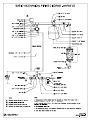
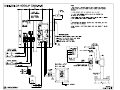
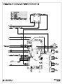
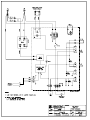
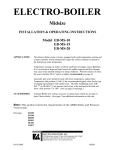
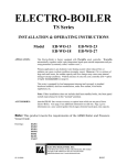
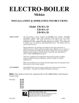
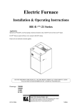
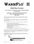
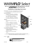
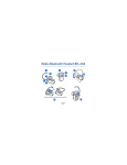
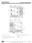
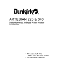
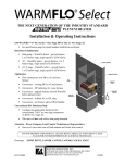
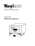
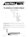
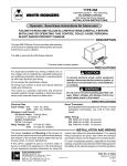
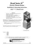
Electric Mini-Boiler TM Installation & Operating Instructions Model EMB-W-9 9 kW 2 GPM minimum flow Application - Low temperature, low pressure, radiant underfloor heating systems. includes a factory installed WarmFlo® aquastat. This model Comment - If this application is for traditional hydronics heating requiring temperatures greater than 14Ø and capacities larger than shown above, contact factory for other Electro-Boiler product series. If this application requires temperatures greater than 140°, this is the wrong model. Contact the distributor or factory for the EB-M*-** model series which is designed for temperatures up to 180°. This series can also do outdoor reset and other features. Accessories – Attached BL001 lists various accessory or option items which are not part of basic Electro-Boiler. Page 1 gives information on a zone control update which stages elements based upon zone capacity. Note: This product meets the requirements of the ASME Boiler and Pressure Vessel Code. Drawings: 10/22/2008 BX304 BH304 BS304 BS309 BD705 BH007 BL001 BI302B TABLE OF CONTENTS Description Page System Components 1 System or Water Flow 1 Room Thermostat Placement 1 Built in Temperature Control 2 Water Flow Calculation 2 Installation Requirements 2 Mechanical Installation 3 Electrical Hookup 4 Water Fill Procedure 6 Operational Tips 7 Troubleshooting Helps 8 Drawings: Piping, install kit Hook-up Internal Wiring (reference information) Schematic, one line Sensor Installation Zones Boiler Accessories 10/22/2008 BX304 BH304 BS304 BS309 BD705 BH007 BL001 BI302B GENERAL As stated, this product series applies to underfloor hydronics heating. The basic components for an electric energy heating system typically includes: 1. 2. 3. 4. 5. Electric Mini-Boiler itself – covered by this manual Thermostat control – covered by this manual Plumbing kit or piping material at the boiler itself - Can be ordered as a kit, reference catalog number EMB-PK. These items are shown on plumbing installation drawing BX304. Circulating pump - Typically sized for head pressure and system flow requirement, typical catalog number EMB-P2. The underfloor circulating tubes and manifolds - Provided and manufactured by others, not covered in this manual. APPROVED TUBING/PIPING When plumbing this boiler and its peripheral parts to the loop system, all plumbing parts and/or tubing must be sealed to prevent entrance of oxygen. Use only tubing or polyethylene tubing with oxygen Diffusion Barrier (ie. PEX). WARMFLO AQUASTAT This model is factory equipped with the WarmFlo® comfort module setup specifically for boiler water temperatures. During installation the sensor must be installed within the pipe well (see Mechanical section) and the controller modulates or regulates the elements to maintain a preset maximum or preset operating temperature. The circuit board has a screwdriver adjustment (see Operational Tips section) for setting the operating temperature point. During initial turn on (slab stat call for heat) both elements come on full. When the water temperature reaches the set point, the first 4.5 kW element begins turning off and on in an attempt to regulate at this specific temperature. Assuming proper flow, the element power will regulate to maintain this preset temperature. If Stage 1 is totally off and the temperature overshoots by 5°, Stage 2 element is also turned off. ROOM THERMOSTAT PLACEMENT Comfort and proper space heating response is a direct relationship to the room thermostat type and the placement of the thermostat sensing bulb. Typically an underfloor heating system can be broken down into two categories. 10/22/2008 Energy storage, water tubing is under the concrete or within the sand base - The controlling thermostat must have a remote bulb, and this remote bulb must sense the concrete slab temperature (slab stat). Coordinated with the concrete pour, install a ¾” PVC, minimum bend radius of 7 inches, and locate at approximately center (vertical) of the concrete slab. The thermostat sensing bulb can later be pushed down this PVC conduit. If the slab is already poured without conduit for slab stat, use electronic remote sensing thermostat such as Electro Industries’ ES-24-SRO. This type of device only requires a ¼” hole drilled in the concrete at some center wall location. Quick response, hydronics tubing just under the concrete surface, no flooring material over the concrete - In this case, heated water can directly radiate into the room, a standard wall mount room thermostat is adequate. Mount room thermostat on an inside wall similar to most heating systems. Comment: If the slab was poured without the conduit, Electro Industries can provide a remote sensing slab stat with a remote sensor requiring only a ¼” hole. If it is at an inside wall, the ¼” hole need only be 1’ or 2” away from the plate. If it is an outside wall you should go in about 24”. Simply insert the sensor about 2” and fill with basic silicone to keep the sensor protected within the hole. 1 BI302B TEMPERATURE CONTROL The hi-limits within this unit are for safety purposes only. The system installation must have a proper responding slab sensing thermostat to properly turn the boiler on and off. If the water flow is greater than the minimum GPM specified, this boiler should not reach hi-limit and the hydronics loop should continue to flow in the normal heating pattern until the operating slab stat is satisfied. If hi-limiting is experienced prior to satisfying the operating slab stat, there is probably a water flow problem. The WarmFlo® aquastat sensor is designed to control the temperature at the set point; however, depending upon the sensor location, water flow through the pipe at the sensor well, and the non-failure of the circuit board; the temperature of this unit should never reach hi-limit (160°). The limits are provided as a safety backup to the WarmFlo® modulator. INFORMATION/WATER FLOW CALCULATIONS Water flow, GPM, can easily be calculated if the temperature rise across the electric boiler can be measured. The formula below can only be used when the temperature rise is stable and the boiler is not hi-limiting. In other words, verify constant current draw and stable outlet temperatures for at least 15 minutes. GPM= Volts x Amps x 3.4 500 x Temp. rise Example: 240 volts x 36 amps x 3.4 500 x 10 degree rise INFORMATION/WATER FLOW CALCULATIONS – METRIC Volts x Amps x 3.587 240 volts x 36 amps x 3.587 L/min = Example: 251.04 x Temp. rise ° C 251.04 x 6° C rise = = 29376 5000 = 30991.68 1506.24 = 5.8 gpm 20.57 L/min INSTALLATION REQUIREMENTS 1. All installation work must be performed by trained, qualified contractors or technicians. Electro Industries, Inc., sponsors installation and service schools to assist the installer. Visit our web site at electromn.com for upcoming service schools. WARNING ALL ELECTRICAL WIRING MUST BE IN ACCORDANCE WITH NATIONAL ELECTRIC CODE AND LOCAL ELECTRIC CODES, ORDINANCES, AND REGULATIONS. WARNING OBSERVE ELECTRIC POLARITY AND WIRING COLORS. FAILURE TO OBSERVE COULD CAUSE ELECTRIC SHOCK AND/OR DAMAGE TO THE EQUIPMENT. CAUTION This unit can only be used for its intended design as described in this manual. Any internal wiring changes, modifications to the circuit board, modifications or bypass of any controls, or installation practices not according to the details of this manual will void the product warranty, the CSA/us certification label, and manufacturer product liability. Electro Industries, Inc., cannot be held responsible for field modifications, incorrect installations, and conditions which may bypass or compromise the built-in safety features and controls. 2. This installation manual and Electro-Boiler products relate only to the addition of the Electro-Boiler to the hydronics system. The owner/installer assumes all responsibility and/or liability associated with any needed installation of the gas/oil boiler, pump, plumbing, system design, etc. Any instructions or comments made within this manual (or factory phone assistance) relating to the hydronics system or backup gas/oil boiler are provided as comments of assistance and “helps” only. 10/22/2008 2 BI302B CAUTION Hazards or unsafe practices could result in property damage, product damage, severe personal injury and/or death. 3. Remember, safety is the installer’s responsibility and the installer must know this product well enough to instruct the end user on its safe use. Safety is a matter of common sense - - a matter of thinking before acting. Professional installers have training and experienced practices for handling electrical, sheet metal, and material handling processes. Use them. CLEARANCES BACK LEFT RIGHT FRONT TOP BOTTOM MINIMUM CLEARANCE FROM SUGGESTED MINIMUM COMBUSTIBLE SURFACES SERVICE CLEARANCE 0 INCH 0 MM 0 INCH 0 MM 1 INCH 25 MM 6 INCHES 152 MM 1 INCH 25 MM 6 INCHES 152 MM 1 INCH 25 MM 24 INCHES 610 MM 1 INCH 25 MM 24 INCHES 610 MM REQUIRED CLEARANCE – 10 INCHES/254 MM AVAILABLE, ELECTRO INDUSTRIES, INSTALL PARTS OR KITS EMB-BK MINI-BOILER PLUMBING KIT BASIC EMB-P2 PUMP KIT 1/25HP BOILER ES-24-SRO STAT DIG SLAB/ROOM/ROOM 24VAC @WFS5 WATER SENSOR 5616 TRANSFORMER HTR 4X4 PLATE 40VA 24VAC 5576 AIR ELIMINATOR 3/4" ROLLAIRTROL 5456A GAUGE PRES/TEMP 75 PSI/320DG F .25" 5453 VALVE RELIEF 30 PSIG .75” NPT MALE 5590 EXPANSION TAN K 40K BTU 20.1 GALLON EMB-PK MINI-BOILER INSTALL KIT PREFERRED EB-5415A ZONE CONTROLLER MECHANICAL INSTALLATION CAUTION Electro Industries Inc. requires the use of dielectric isolation between the boiler vessel supply and return piping when the boiler is plumbed using copper or any other dissimilar metal. Damage to the vessel caused by galvanic corrosion voids Electro Industries’ warranty. Reference drawing BX304 At the outlet pipe the first fitting must be the supplied Tee with the sensor well fitting. It is important that the WarmFlo® aquastat sensor be as close as possible to the vessel, reference detail A on drawing BH304. Please reference BD705 for proper installation of the sensor. After the Tee and the sensor have been permanently installed, route the sensor cable along the right side of the unit and properly affix (do not puncture cable) to the wall. The plumbing components and piping layout shown on drawing BX304 has been very carefully picked and should be plumbed as shown. When following this diagram, the water fill procedure becomes very simple and almost guarantees the removal of all air or prevents air locking problems. Experienced hydronic heating installers may be able to eliminate components such as regulated fill valve, check valve, temperature gauge, etc., but the inclusion of these components guarantees installation and initial operating success. The key mechanical components required include: 10/22/2008 3 BI302B Boiler/Plumbing Kit Placement – This model series is wall hung and the vessel must be vertical. The plumbing kit items are located adjacent to the boiler housing itself as shown on drawing BX304. For future servicing, the unit itself must be installed a minimum of 18” above the floor. The elements are screwed in from the bottom. Allow adequate space for cover removal and maintenance. Expansion Tank - As a closed loop hydronic heating system, a minimal expansion tank is required. This can be an air diaphragm tank as provided in the plumbing kit or a basic “empty” tank where air is compressed at the tank top. Temperature/Pressure Gauge - Recommended to observe the operation of the system. Actually a temperature gauge at the inlet and outlet is desirable. Pressure Safety Valve - This is required at the hot outlet and is furnished as a loose component with the boiler unit itself. Failure to install the provided, 30 PSI, pressure relief valve as shown void warranty and the CSA product listing. Add the necessary pipe extension from the relief valve to the floor to prevent water damage on this unit or surrounding area. Gate Valve/Drain Valve - These are for servicing and easy fill purposes. Circulating Pump - Depending upon system lift and system loop resistance (feet of head), the proper circulating pump is required to guarantee the minimum GPM flow as specified on the cover sheet. Comment: Circulator pump can be in the outlet or inlet. However, the circulator pump should “pump away from” the expansion tank. Air Vent Relief - Whenever there is a plumbing point higher than any of the components shown or an adjacent line (any vertical “U” trap), an air vent valve should be provided. Building Water Supply Connection – Reference drawing BX304, note 4, some local building codes require sophisticated check valve or anti-syphon check valve when the hydronics heating system is permanently connected to the domestic water system. The intent of this connection is temporary and for fill purposes only. The installer has the responsibility of complying with local building codes. ELECTRICAL HOOKUP Reference drawing BH304. WARNING DISCONNECT ALL ELECTRICAL POWER BEFORE ELECTRICALLY CONNECTING OR SERVICING THE UNIT. FAILURE TO DISCONNECT THE ELECTRICAL POWER BEFORE WORKING ON THIS PRODUCT CAN CREATE A HAZARD LEADING TO PERSONAL INJURY OR DEATH. 1. Panel breaker sizes – 4.5 kW Mini-Boiler will require 30-amp breaker, copper wire. 9 kW Mini-Boiler will require 50-amp breaker, copper wire. 2. 24Ø Volt Power Source – route and install the proper current carrying conductors, suggested by local codes, from service panel fuse or circuit breaker. Nameplate shows current & KW rating. NOTE: This model series is designed and equipped for 240-volt residential single phase. If this unit is used on 208 volt, energy capacity is reduced and there is a possibility of intermittent relay operation. Call factory for 208-volt application. The source is either from the standard service panel or may be part of an off-peak separately metered panel/CT metered enclosure. Consult with local utility if questions on off-peak installations. Since this unit is less than 10 kW, no fusing or circuit breaker at the boiler itself is required. The 240-volt (L1, L2, with copper ground) is connected directly to the left bottom terminal block. 10/22/2008 4 BI302B WARNING USE ONLY COPPER WIRE FOR CONNECTION TO THE CIRCUIT BREAKER TERMINALS AND INSIDE THIS PRODUCT’S CABINET. WARNING TO AVOID THE RISK OF ELECTRIC SHOCK OR DEATH, WIRING TO THE UNIT MUST BE PROPERLY GROUNDED. FAILURE TO PROPERLY GROUND THE UNIT CAN RESULT IN A HAZARD LEADING TO PERSONAL INJURY OR DEATH. 3. Circulating Pump – the two screw terminals (orange wires) represent a switch closure (see drawing – 10-amp maximum) to operate the circulating pump motor. Voltage for the pump must come from a separate source. Wiring entrance must be left KO, do not combine with thermostat cable or other control wiring. 4. Operating Thermostat – zone valve dry contact end switch is an operating contact, direct wired thermostats include: Standard Mechanical – connect to control board “R” and “W”. Important! -Set thermostat internal heat anticipator to Ø.2. Electro-Stat - (ES-24-SRO) 4 wire connection required. This is an electronic remote sensing device, remote sensor can be up to 50 feet, cut and splice as required. Use only stranded wire, shielded cable not required. The primary advantages include the capability for longer sensor and the sensor itself is less than ¼”. This means it can be installed after the slab is complete by simply drilling a ¼” hole, 1/8” slot, etc. slightly out from an inside wall. * R to R, W to W, C to C, green to ground * Use drawing EH304 (with ES product) for hookup, note change in load control connection. WARNING VOLTAGE SEPARATION IS REQUIRED. THE 24Ø POWER AND PUMP WIRING MUST REMAIN LEFT OF THE BOTTOM PIPE. THE THERMOSTAT WIRES AND LOAD CONTROL WIRING (BLUE & BLUE/WHT) MUST EXIT AND REMAIN ON THE RIGHT SIDE OF THE BOTTOM PIPE. 5. Load Management Interrupt Control – this Mini-Boiler product has been pre-wired and designed for a power company load management receiver connection. This should not be altered in any manner! A. Remove blue jumper wire B. Extend or connect the two terminal screw points to the power company load control device. As shipped, this unit is only equipped for off-peak =N.C. logic. If reversed logic is required, contact the factory for modification. Optional – if load management is not used, simply leave the blue wire jumper connected as shipped from manufacturer. Also for Electro-Stat the load control connection is at the Electro-Stat “R” terminal. 6. Zone Valve – do not power from EMB internal transformer. Contractor needs to install separate 24VAC transformer to operate zone valves. Suggest adding zone interlock control, EB-5415A . Call factory. 7. Inspection/final check – Verify all electrical connections are tight (including factory connections), verify there is proper spacing between all power and electrical wire/terminals, and verify top high limit manual reset is “in”. During shipping freight vibration there are times when the boiler vessel top manual reset high limit is “popped out”. WATER ADDITIVES 1. Unless the source water is unusually poor and/or rust elements, additives are not required. It is recommended the water source as shown on drawing BX304 comes through the household water softener. 10/22/2008 5 BI302B 2. Impurities within a closed loop hydronics boiler are considerably less damaging than the typical domestic water heater. In a closed loop electric boiler, the water impurities “boil out” and the system essentially reverts to pure water. As a closed system, this “pure water” becomes the operating mode. In the case of domestic water tank, there is always new water entering with new impurities. 3. However, if additives are required, use the recommendations and source from your local professional plumber, specializing in hydronics heating systems. WATER FILL PROCEDURE The following procedure only applies to the prepackaged plumbing kit and/or when the system is plumbed exactly as shown on drawing BX304. 1. Connect the temporary household water supply source (probably hose connection) to the "supply water connection" input. NOTE: If supply water connection is permanent, some local building codes may require special anti-siphon check valve, PRZ check valve, or equivalent between the Mini Boiler fill regulator and the domestic water source or the city water connection. 2. Connect a drain hose to lower hose bib, "drain valve". 3. Open "drain valve" and close "inlet gate valve" (between drain valve and boiler bottom inlet). 4. Verify “top gate valve” is open. 5. Do not apply 24Ø volt heating power during water fill sequence. 6. Open "water supply valve" and open household water supply source. This may be at normal household pressure (4Ø to 6Ø PSI), the auto-fill value regulator keeps the hydronics loop at its proper low pressure. 7. Allow system to circulate, discharging through drain valve, for at least 1Ø minutes. 8. Put your ear against the metal pipe and listen for air bubbles. If the water flow is consistent and quiet, the system is probably purged and water filled. 9. Close the "drain valve". Open the "inlet gate valve". 10. The cold system pressure at the gauge should be approximately 1Ø to 14 PSI. 11. Close "water supply valve" and disconnect water supply. 12. Optional – The circulating pump can be energized during this fill operation by having the 240 power main source breaker off and simply jumpering the 2 screw terminals for the pump wire connection. 10/22/2008 6 BI302B Figure 1 OPERATIONAL TIPS 1. Indicator lights – there is a set of four indicator lights on the lower right corner of the front cover with an identical set of four indicator lights on the internal circuit board itself. Figure 1 is a reproduction of the front decal giving definition and information for using these indicator lights. Note the statement that there must be a call for heat before attempting to interpret the indicator lights. 2. 24Ø volt element power current flow can be measured when the external operating thermostat is calling for heat. There are no delays. Assumes off-peak mode. 3. The operating thermostat heat call can be verified by the red LED marked “Mini-Boiler heat on” located on front cover. 4. The 160° (71° C) hi-limit is automatic reset. 5. The 205° (96° C) hi-limit is manual reset and under the cover, located on the vessel top, left. Warning: This 205° (96° C) manual reset controls the 240 power to the elements. Therefore, open the boiler disconnect prior to removing cover and prior to attempting to reset this limit. Note: Reset tab is brass in color and located on the side of the hi-limit. 6. Via a small pin jumper arrangement on the control board, the circulator pump can be a direct function of the “W” input or interrupted by the load control device (even though there is a W input). This diagram illustrates this pin jumper arrangement. This unit is factory setup in the “W” position meaning the pump will always run as a direct function of “R” to “W” operating thermostat. By simply moving this black 2-position jumper to the “L” the pump will be turned off during load control interrupt. 7. At outlet temperatures of approximately 120 F (53° C), the maximum system pressure should be approximately 18 PSI (124 kPa). If the PSI (or kPa) increase from cold water to operating hot water is more than approximately 3 to 4 PSI (20.6 to 27.5 kPa), the expansion tank is too small. 8. Check for water leaks and repair as required. 9. If flow seems to be a concern, determine both inlet and outlet water temperature and apply GPM (L/min) formula detailed in previous section “Information/Water Flow Calculations”. 10/22/2008 7 BI302B WARMFLO AQUASTAT OPERATION Sensor cable installation – see previous paragraph, Mechanical. Determine from floor tubing supplier design outline the desired floor temperature. Typically this relates to floor covering and tube placement design. Set the aquastat set point for desired warm water outlet. The temperature set point is selected by a small screwdriver switch on the control board. Use the following chart: Switch Position 0 1 2 3 4 5 6 7 Set Point 85 95 105 115 125 135 145 150 The green LED on the circuit board is on whenever Stage 1 electric element is on. This can either be full on, pulsing at a slow rate, or full off. TROUBLESHOOTING HELPS Monitor – the green LED to the left of the dial switch not only indicates the first element operating on/off, but also provides some sensor quality information. If this LED is pulsing, there is either a shorted sensor, open wire to the sensor, or some sensor wiring error. The internal logic is not receiving temperature information from the sensor tip. The default for a bad sensor – boiler operates at half capacity, stage 1 on, stage 2 off. Sequence At heat call, elements 1 and 2 are full on. As the outlet temperature approaches the set point, element 1 begins to pulse modulate. At set point element 1 is off or 0%. At +5° above set point element 2 turns off. At set point element 1 again begins to modulate. At 5° below set point element 1 is at 100% and element 2 would again turn on. Mechanical hi-limit, top vessel screw-in, automatic reset – this is at about 160° F, opens the red/white wire loop. This can be monitored by the “Auto Reset” front indicator light. As the water cools to approximately 120° it should self reset and restart. Manual reset limits – surfaced mounted to the top of the vessel, opens at 205° F. This actually opens the current carrying leg to each element and prevents 240 power from reaching the element. This can be monitored from the “Manual Reset” front indicator light. To reset this device, notice a small shiny lever protruding from one side of the black insulator. Simply push this lever inward and it should snap. Comment: These lights will only be active during a heat call and when the element relay is closed. WARMFLO TEMPERATURE BYPASS TROUBLESHOOTING OR TESTING Adding a jumper between “W” screw terminal and tab marked “E” bypasses the temperature sensing and WarmFlo control. In other words, with the jumper installed a “W” input represents 9 kW, full on. 10/22/2008 8 BI302B MINI-BOILER HOOKUP (EMB-W-9) NOTES: 1. THIS UNIT HAS A FACTORY-INSTALLED BLUE JUMPER THAT BYPASSES THE LMC MODE. WHEN LMC OPTION IS USED, REMOVE JUMPER BEFORE INSTALLING. FUSE SHOWN 2A WITH MAX. COVER REMOVED NO LIGHTS 3. J4 OPERATE MUST ON-BOARD INTERNAL WIRING 2. SHOWN 4. ANY HAVE LED 2-WIRE ONLY ON THERMOSTAT EXTERNAL LED PLUGGED TO CALL IN FOR OR HEAT. JUMPERED FOR OPERATE. STAT OR END SWITCH CONTACT CAN BE USED TO OPERATE R & W, ELECTRO-STAT SHOWN AS EXAMPLE ONLY. 5. 3/A1 4/A2 2/T1 1/L1 6. TRANSFORMER FOR INTERNAL CIRCUITS ONLY. ZONE VALVES, ETC. MUST HAVE T6 240 VAC K2 THEIR OWN 24V SOURCE. T5 COM 7. HIGH VOLTAGE & LOW VOLTAGE WIRING MUST HAVE MINIMUM 1" (2.5CM) SPACING. TR1 NO UPCB5621 W2 W3 CS T1 COM T7 T10 160 205 T11 ARL NO T2 A N1 T8 K1 TEMP. SENSOR 1 L W o BLK G SEE NAMEPLATE FOR CIRCULATING PUMP A E T2 SWITCH CLOSURE POWER CIRCUIT IS EXTERNAL. CURRENT RATING. CONTACT RATING - G 10A AT 120 VOLTS. COPPER ONLY 160 HL LED4 COM L2 W5 2 T3 T4 TB1 SW1 TB2 1 LED3 J4 W4 T9 UAS300 EL MODE 3 205°F (96°C) MANUAL RESET LIMIT (RED) 160°F (71°C) AUTO RESET LIMIT (RED) UTILITY OFF-PEAK (AMBER) MINI-BOILER HEAT ON (RED) 1 LED2 J3 LED1 J2 HEAT ON 1 SET TEMP. L1 L2 G BLUE BLU/WHT R W C W1 3/4"-1/4" BUSHING (XBSH7125) TEMP. SENSOR POWER TB3 CIRCUIT 3/4" TEE (XTEE7000) 2 1 SOURCE LIGHTS J1 TB3 RED L1 INDICATOR o 205 HL RED BREAKER 1/4" X 3/4" PIPE WELL (#5533) BLK L1 COM L2 DETAIL CIRCUIT SCALE BREAKER A-A 3:1 WATER SENSOR 120VAC ELECTRO-STAT NEUTRAL REFERENCE PROPER (ES-24-BR) SENSOR BD705 FOR INSTALLATION T-STAT CABLE PUMP (TB2 "C") MINI-BOILER OUTLET (TB2 "W") LMC PIPE (TB2 "R") 4 ELECTRO INDUSTRIES, INC. MONTICELLO, MN 55362 BLUE (TB1) BLUE (TB1) SLAB SENSOR BH304 P.1 Rev.G 03-06-07 MINI-BOILER HOOKUP (EMB-W-9) MULTI-ZONE, ANY NUMBER OR SIZE. ELECTRO-STAT ELECTRO-STAT (ES-24-BR) (ES-24-BR) ZONE 1 ZONE 2 4-WIRE 4-WIRE THERMOSTAT THERMOSTAT C GREEN CABLE GREEN CABLE W R C W R SLAB SENSOR SLAB SENSOR #5616 TRANSFORMER C FUSE SHOWN COVER NO 2A WITH MAX. 24V REMOVED INTERNAL 120V POWER FROM PUMP CB R WIRING SHOWN TYPICAL ZONE W 4/A2 M YEL 2/T1 RED NO COM T1 W3 T2 T11 ARL NO 205 N1 TB3 CURRENT RATING. W5 CONTACT RATING - G UAS300 EL MODE J3 160°F (71°C) AUTO RESET LIMIT (RED) UTILITY OFF-PEAK (AMBER) MINI-BOILER HEAT ON (RED) 1 T3 T4 TB1 SW1 TB2 HEAT ON LED1 1 J2 SET TEMP. L1 L2 G 3 LIGHTS R 205°F (96°C) MANUAL RESET LIMIT (RED) 1 LED3 J4 W4 T9 W o LED2 POWER CIRCUIT IS EXTERNAL. INDICATOR 1 L 160 HL LED4 CIRCULATING PUMP 10A AT 120 VOLTS. 1 J1 COM COPPER ONLY #5544 1 o BLK E M W 205 HL K1 TEMP. SENSOR T2 YEL T10 160 T8 RED SWITCH CLOSURE - YEL RED 3/A1 COM W2 CS G W C OR T5 UPCB5621 L2 SERIES TR1 T7 L1 HONEYWELL V8043F 240 VAC K2 SEE NAMEPLATE FOR - EXAMPLE: RED 1/L1 T6 END SWITCH EQUIVALENT #5544 PAGE 1 VALVE STAT - ISOLATED RED SEE C - 2-WIRE YEL BLUE BLU/WHT R W C W1 W R Room Thermostats SOURCE POWER CIRCUIT BREAKER #1 T-STAT L1 ZONE VALVES #2 CABLE (TB2 "W") L2 (TB2 "R") PIPING CIRCUIT BREAKER MANIFOLD LMC 120VAC NEUTRAL NOTES: 1. ZONE VALVE END SWITCHES, MUST BE ISOLATED CONTACT. PUMP (TB1) BLUE (TB1) BLUE 2. USE TRANSFORMER OPERATING ZONE VALVE SYSTEM. DO NOT USE BOILER TRANSFORMER 3. SAME HOOK-UP FOR ELECTRO INDUSTRIES, INC. MONTICELLO, MN 55362 ANY FOR ZONE VALVES. NUMBER OF ZONES. BH304 P.2 Rev.G 03-06-07 ELECTRO-BOILER SENSOR INSTALLATION Once the pipe well has been installed. Liberally apply the supplied heat compound around the tip of the Warmflo sensor. Then gently insert sensor into pipe well. Note: Using the tip of your finger, or another non-piercing object will aid in the insertion of the rubber grommet. Once the grommet has been inserted into the well gently press the sensor until it reaches the bottom of the pipe well. Installation complete. 09/26/2001 1 BD705 WARMFLO BOILER ZONE VALVE HOOKUP ELECTRO-STAT ZONE ELECTRO-STAT 1 ZONE SLAB STAT SLAB ELECTRO-STAT 2 ZONE STAT SLAB 4-WIRE 4-WIRE 4-WIRE THERMOSTAT THERMOSTAT THERMOSTAT CABLE CABLE STAT CABLE R C W GREEN W GREEN GREEN C 3 R SLAB SENSOR SLAB C W R SENSOR SLAB TO TRANSFORMER ADDITIONAL SLAB R 120V SENSOR TYPICAL 24V W C C YEL YEL M - 2-WIRE - ISOLATED - EXAMPLE: V8043F STAT END STATS (ZONES) ZONE VALVE SWITCH YEL W HONEYWELL YEL C SERIES OR YEL W M YEL C M WARMFLO SERIES 1 1 RED RED RED RED RED ELECTRO-BOILER RED EQUIVALENT 1 EB-W-** TO EMB-W-9 R ADDITIONAL ZONE 3 3 VALVES 3 Room Thermostats W NOTES: #1 ZONE VALVES #2 #3 1. ZONE VALVE END SWITCHES, MUST BE ISOLATED CONTACT. 2. USE TRANSFORMER NOT 3. ZONE CONTROLLER SEE DRAWING PIPING ELECTRO INDUSTRIES, INC. MONTICELLO, MN 55362 OPERATING ZONE USE BOILER TRANSFORMER BH009 FOR CAN BE USED TO FOR VALVE SYSTEM. DO ZONE VALVES. SIMPLIFY HOOKUP. DETAILS. MANIFOLD BH007 P.1 Rev.C 03-06-07 WARMFLO BOILER ZONE VALVE HOOKUP ZONE SLAB 1 ZONE STAT EI P/N #7101 2 ZONE SLAB EI P/N #7101 EI P/N #7101 2-WIRE 2-WIRE 2-WIRE THERMOSTAT THERMOSTAT THERMOSTAT CABLE CABLE CABLE R R IN-SLAB IN-SLAB IN-SLAB SENSOR SENSOR SENSOR W/ 10 FT. W/ 10 FT. W/ 10 FT. CABLE CABLE TO TRANSFORMER ADDITIONAL SLAB R YEL C C YEL M - 2-WIRE - ISOLATED - EXAMPLE: HONEYWELL STAT END STATS (ZONES) TYPICAL ZONE VALVE 24V STAT R CABLE 120V 3 SLAB STAT YEL SWITCH C V8043F SERIES OR YEL M YEL C YEL M WARMFLO SERIES 1 1 RED RED RED RED RED ELECTRO-BOILER RED EQUIVALENT 1 EB-W-** TO EMB-W-9 R ADDITIONAL ZONE 3 3 VALVES 3 Room Thermostats W NOTES: #1 ZONE VALVES #2 #3 1. ZONE VALVE END SWITCHES, MUST BE ISOLATED CONTACT. 2. USE NOT 3. TRANSFORMER OPERATING USE BOILER ZONE CONTROLLER SEE DRAWING PIPING ELECTRO INDUSTRIES, INC. MONTICELLO, MN 55362 ZONE VALVE SYSTEM. DO TRANSFORMER FOR ZONE CAN BH009 FOR BE USED VALVES. TO SIMPLIFY HOOKUP. DETAILS. MANIFOLD BH007 P.2 Rev.C 03-06-07 BOILER ACCESSORIES ZONE CONTROLLER This will simplify your wiring and make zoning applications much easier. In addition, enhanced communicating features have the ability to stage the electric boiler based upon the connected zone capacity. Pumps, Actuators, Valves Standard Features EB-ZTA-1 - install within boiler cabinet EB-ZEA-1 - with enclosure and 40VA transformer EB-ZEA-2 - add additional 4, enclosure and 40VA • Utility load control • Terminal block wiring, visual wiring layout • Indicator lights showing zone operation Pumps • 24-volt, 40VA transformer 120/208/240 connection Zone Valves EB-Z2P - two pumps with priority and dual temp. EB-ZTS-1 - install within boiler cabinet, encl. option EB-ZTS-2 - add additional 4, enclosure and 40VA • Fuse protection • Priority option • Dual temperature operation • Applies to digital or standard thermostats • Dial switch, select each zone capacity All Others EB-ZXA-1 - universal, pumps or valves, non-communicating, for any boiler EB-ZS-4 - automatic staging system for Brand X boilers or dual EB-R, -L, -E Series EB-ZC-4 - wiring and convenience interface, isolated boiler end switch EB-5415A - low cost, 2 or 3 zones, sheds one boiler stage (Mini-Boiler enhancement) SLAB STAT Sensing and controlling the system based upon radiant floor surface temperature or the concrete mass has very positive benefits. Radiant floor air stat in the same area as a forced air roomstat presents serious control problems. A remote sensing slab stat for the radiant floor removes this issue. Remote sensing slab stat is required for storage applications. ES-24-BR SWITCHING RELAY - EE-5051 This DPDT 24-volt switching relay provides a convenient solution to any AC or DC application. MULTI-BOILER - EB-C-STG5 Electrically connects between 2nd and 3rd, 3rd and 4th, etc. OTHER OPTIONS • • • • Ideal for zone pumps 24V coil 120V, 10A, contact sets Easy to wire and nicely packaged SOT-1 5701 5702 EB-S-SB WF-ANZ* Switchover to standby, total run time Single feed bus for 2 CB’s (SQ-D CB) Single feed bus for 3 CB’s (SQ-D CB) Dual boiler option for EB-S Series WarmFlo Analyzer, now applicable to WO and WA Series Specifications subject to change without notice, all rights reserved. TWO SUPPLY WATER TEMPERATURE REQUIREMENT • Handled as the priority zone on multi-zone (EB-ZEA-1) or two pump (EB-Z2P) controllers • Priority switch on, zone 1 active - TS boiler automatically changes to 150° (or selection 176°) supply water setting • • All other zones are held off With zone 1 satisfied or 60-minute timeout, the boiler automatically returns to the preset temperature and reacts to the other zones Low Temp High Temp Radiant, slab Radiant, staple up Radiant, slab Baseboard Radiant, slab Fan coil Radiant, slab Water heater, side arm Radiant, slab Hanging unit heater (garage, shop, etc.) INSTALLATION PLUMBING KITS These installation kits provide the critical plumbing components needed for easy installation of the Electro-Boiler. In addition to the items shown in the matrix below, each kit includes all necessary ball valves, drain valve, tees, elbows, nipples, bushings, couplings, etc. for direct connection to circulator pump and/or manifold. Electro Industries’ boilers come standard equipped with outlet temperature/pressure gauge, pressure relief safety valve, and when applicable, the WarmFloTM electronic control sensors. These kits provide the additional components for easy installation: Model Application Return Gauge EMB-BK All EMB Series EMB-PK All EMB Series EB-PK-M EB-MS, -MA, -MO Series EB-BK-TS EB-S, -WA, -WO Series EB-PK-TS EB-S, -WA, -WO Series Expansion Tank Air Vent 2.1 gal. (7.9 L), 40,000 Btu/h Basic float type 2.1 gal. (7.9 L), 40,000 Btu/h Enhanced air separator, EAS 4.5 gal. (17 L), 135,000 Btu/h Enhanced air separator, EAS 4.5 gal. (17 L), 135,000 Btu/h Basic float type 4.5 gal. (17 L), 135,000 Btu/h Enhanced air separator, EAS CIRCULATING PUMPS 5585 - Mini-Boiler & 10 kW TS Series • 120V, 1/25 HP, maintenance-free wet rotor circulator • Pump curve example - 5 GPM (19 L) @ 11 ft. of head (32.9 kPa) 07/24/2007 5586 - TS Series, Standard • 120V, 1/6 HP, maintenance-free oil lubricated circulator • Pump curve example - 10 GPM (37.8 L) @ 20 ft. of head (50.8 kPa) 5578 - 3/4” Pipe 5582 - 1” Pipe 5579 - 1-1/4” Pipe • Two flanges, with isolation valve BL001 Electro Industries, Inc. Limited Product Warranty Effective October 1, 2007 Electro Industries, Inc. warrants to the original owner, at the original installation site, for a period of two (2) years from date of installation, that the product and product parts manufactured by Electro Industries are free from manufacturing defects in materials and workmanship, when used under normal conditions and when such product has not been modified or changed in any manner after leaving the plant of Electro Industries. If any product or product parts manufactured by Electro Industries are found to have manufacturing defects in materials or workmanship, such will be repaired or replaced by Electro Industries. Electro Industries shall have the opportunity to directly, or through its authorized representative, examine and inspect the alleged defective product or product parts. Electro Industries may request that the materials be returned to Electro Industries at the owner’s expense for factory inspection. The determination as to whether product or product parts shall be repaired, or in the alternative replaced, shall be made by Electro Industries or its authorized representative. Electro Industries will cover reasonable labor costs to repair defective product or product parts for ninety (90) days after installation. TWENTY YEAR (20) LIMITED WARRANTY ON BOILER ELEMENTS AND VESSELS Electro Industries, Inc. warrants that the boiler elements and vessels of its products are free from defects in materials and workmanship through the twentieth year following date of installation. If any boiler elements or vessels are found to have a manufacturing defect in materials or workmanship, Electro Industries will replace them. TWENTY YEAR (20) LIMITED WARRANTY ON SPIN FIN ELEMENTS Electro Industries, Inc. warrants that the spin fin elements of its products are free from defects in materials and workmanship through the twentieth year following date of installation. If any spin fin elements are found to have a manufacturing defect in materials or workmanship, Electro Industries will replace them. FIVE YEAR (5) LIMITED WARRANTY ON OPEN WIRE ELEMENTS Electro Industries, Inc. warrants that the open wire elements of its products are free from defects in materials and workmanship through the fifth year following date of installation. If any open wire elements are found to have a manufacturing defect in materials or workmanship, Electro Industries will replace them. Page 1 of 2 XX017 THESE WARRANTIES DO NOT COVER: 1. Costs for labor for removal and reinstallation of an alleged defective product or product parts, transportation to Electro Industries, and any other materials necessary to perform the exchange, except as stated in this warranty. Replacement material will be invoiced to the distributor in the usual manner and will be subject to adjustment upon verification of defect. 2. Any product that has been damaged as a result of being improperly serviced or operated, including, but not limited to, the following: operated with insufficient water or airflow, allowed to freeze, subjected to flood conditions, subjected to improper voltages or power supplies, operated with airflow or water conditions and/or fuels or additives which cause unusual deposits or corrosion in or on the product, chemical or galvanic erosion, improper maintenance or subject to any other abuse or negligence. 3. Any product that has been damaged as a result of natural disasters, including, but not limited to, the following: lightning, fire, earthquake, hurricanes, tornadoes or floods. 4. Any product that has been damaged as a result of shipment or handling by the freight carrier. It is the receiver’s responsibility to claim and process freight damage with the carrier. 5. Any product that has been defaced, abused, or suffered unusual wear and tear as determined by Electro Industries or its authorized representative. 6. Workmanship of any installer of the product. This warranty does not assume any liability of any nature for unsatisfactory performance caused by improper installation. 7. Transportation charges for any replacement part or component, service calls, normal maintenance; replacement of fuses, filters, refrigerant, etc. CONDITIONS AND LIMITATIONS: 1. If at the time of a request for service the original owner cannot provide an original sales receipt or a warranty card registration then the warranty period for the product will have deemed to begin thirty (30) days after the date of manufacture and NOT the date of installation. 2. The product must have been sold and installed by a licensed electrical contractor, a licensed plumbing contractor, or a licensed heating contractor. 3. The application and installation of the product must be in compliance with Electro Industries’ specifications as stated in the installation and instruction manual, and all state and federal codes and statutes. If not, the warranty will be null and void. 4. The purchaser shall have maintained the product in accordance with the manual that accompanies the unit. Annually, a qualified and licensed contractor must inspect the product to assure it is in proper working condition. 5. All related heating components must be maintained in good operating condition. 6. All lines must be checked to confirm that all condensation drains properly from the unit. 7. Replacement of a product or product part under this limited warranty does not extend the warranty term or period. 8. Before warranty claims will be honored, Electro Industries shall have the opportunity to directly, or through its authorized representative, examine and inspect the alleged defective product or product parts. Remedies under this warranty are limited to repairing or replacing alleged defective product or product parts. The decision whether to repair or, in the alternative replace, products or product parts shall be made by Electro Industries or its authorized representative. THESE WARRANTIES DO NOT EXTEND TO ANYONE EXCEPT THE ORIGINAL PURCHASER AT RETAIL AND ONLY WHEN THE PRODUCT IS IN THE ORIGINAL INSTALLATION SITE. THE REMEDIES SET FORTH HEREIN ARE EXCLUSIVE. ALL IMPLIED WARRANTIES, INCLUDING WARRANTIES OF MERCHANTABILITY AND FITNESS FOR A PARTICULAR PURPOSE, ARE HEREBY DISCLAIMED WITH RESPECT TO ALL PURCHASERS OR OWNERS. ELECTRO INDUSTRIES, INC. IS NOT BOUND BY PROMISES MADE BY OTHERS BEYOND THE TERMS OF THESE WARRANTIES. FAILURE TO RETURN THE WARRANTY CARD SHALL HAVE NO EFFECT ON THE DISCLAIMER OF THESE IMPLIED WARRANTIES. ALL EXPRESS WARRANTIES SHALL BE LIMITED TO THE DURATION OF THIS EXPRESS LIMITED WARRANTIES SET FORTH HEREIN AND EXCLUDE ANY LIABILITY FOR CONSEQUENTIAL OR INCIDENTAL DAMAGES RESULTING FROM THE BREACH THEREOF. SOME STATES DO NOT ALLOW THE EXCLUSION OR LIMITATION OF INCIDENTAL OR CONSEQUENTIAL DAMAGES, SO THE ABOVE LIMITATIONS OR EXCLUSIONS MAY NOT APPLY. PRODUCTS OR PARTS OF OTHER MANUFACTURERS ATTACHED ARE SPECIFICALLY EXCLUDED FROM THE WARRANTY. THIS WARRANTY GIVES YOU SPECIFIC LEGAL RIGHTS, AND YOU MAY HAVE OTHER RIGHTS WHICH VARY UNDER THE LAWS OF EACH STATE. IF ANY PROVISION OF THIS WARRANTY IS PROHIBITED OR INVALID UNDER APPLICABLE STATE LAW, THAT PROVISION SHALL BE INEFFECTIVE TO THE EXTENT OF THE PROHIBITION OR INVALIDITY WITHOUT INVALIDATING THE REMAINDER OF THE AFFECTED PROVISION OR THE OTHER PROVISIONS OF THIS WARRANTY. Page 2 of 2 XX017