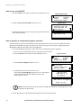
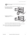
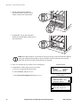
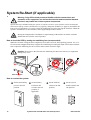
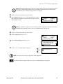
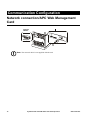
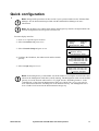
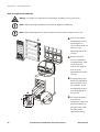
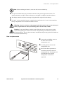
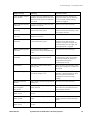
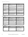
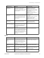
1
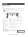
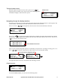
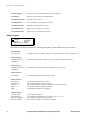
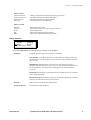
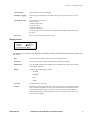
Operation Symmetra® PX 10-40 kW 400 V and 208 V About this Manual This manual is intended for the users of the Symmetra® PX 10-40 kW UPS. Companion manuals For additional information, see the following Symmetra PX manuals: 400V • Receiving and unpacking (990-4150) • Safety (990-2984) • Installation (990-4149) 208V • Receiving and unpacking (990-4150) • Safety (990-2984) • Installation (990-4063) How to find updates to this manual Check for updates at the APC Web site www.apc.com. Look for the latest letter version of the manual. 990-4147D-001 Symmetra PX 10-40 kW 400 V and 208 V Operation Contents Safety ................................................................................ 1 Overview........................................................................... 2 Display Interface. . . . . . . . . . . . . . . . . . . . . . . . . . . . . . . . . . . . . . . . . . 2 Overview . . . . . . . . . . . . . . . . . . . . . . . . . . . . . . . . . . . . . . . . . . .2 Top-level status screen . . . . . . . . . . . . . . . . . . . . . . . . . . . . . . . .2 Top-level menu screen . . . . . . . . . . . . . . . . . . . . . . . . . . . . . . . . .3 Navigating through the display interface . . . . . . . . . . . . . . . . . . .3 Control screen . . . . . . . . . . . . . . . . . . . . . . . . . . . . . . . . . . . . . . .3 Status screens . . . . . . . . . . . . . . . . . . . . . . . . . . . . . . . . . . . . . . .4 Setup screens . . . . . . . . . . . . . . . . . . . . . . . . . . . . . . . . . . . . . . .5 Accessories screen . . . . . . . . . . . . . . . . . . . . . . . . . . . . . . . . . . .6 Logging screen . . . . . . . . . . . . . . . . . . . . . . . . . . . . . . . . . . . . . .6 Display screen . . . . . . . . . . . . . . . . . . . . . . . . . . . . . . . . . . . . . . .7 Diags screens . . . . . . . . . . . . . . . . . . . . . . . . . . . . . . . . . . . . . . .8 Help screens . . . . . . . . . . . . . . . . . . . . . . . . . . . . . . . . . . . . . . . .8 Operation.......................................................................... 9 Operation Procedures . . . . . . . . . . . . . . . . . . . . . . . . . . . . . . . . . . . . . 9 How to perform a total power off . . . . . . . . . . . . . . . . . . . . . . . . .9 How to turn load ON/OFF . . . . . . . . . . . . . . . . . . . . . . . . . . . . . .10 How to transfer to maintenance bypass operation . . . . . . . . . . .10 How to return to on-line operation from maintenance bypass operation . . . . . . . . . . . . . . . . . . . . . . . . . . . . . . . . . . . .11 System Re-Start (if applicable) . . . . . . . . . . . . . . . . . . . . . . . . . . . . . 14 How to level the UPS by setting the stabilizing feet (recommended) . . . . . . . . . . . . . . . . . . . . . . . . . . . . . . . . . . . . .14 How to re-start the system . . . . . . . . . . . . . . . . . . . . . . . . . . . . .14 Communication Configuration ..................................... 16 Network connection/APC Web Management Card . . . . . . . . . . . . . 16 Quick configuration . . . . . . . . . . . . . . . . . . . . . . . . . . . . . . . . . . . . . . 17 990-4147D-001 Symmetra PX 10-40 kW 400 V and 208 V Operation i Maintenance................................................................... 18 Parts Replacement . . . . . . . . . . . . . . . . . . . . . . . . . . . . . . . . . . . . . . . 18 How to obtain replacement modules . . . . . . . . . . . . . . . . . . . . . .18 Replacement parts and numbers . . . . . . . . . . . . . . . . . . . . . . . .18 How to replace the power modules . . . . . . . . . . . . . . . . . . . . . . .19 How to replace the batteries . . . . . . . . . . . . . . . . . . . . . . . . . . . .20 How to replace cards . . . . . . . . . . . . . . . . . . . . . . . . . . . . . . . . .21 Troubleshooting ............................................................ 22 General status . . . . . . . . . . . . . . . . . . . . . . . . . . . . . . . . . . . . . .22 General fault . . . . . . . . . . . . . . . . . . . . . . . . . . . . . . . . . . . . . . .24 Module failure . . . . . . . . . . . . . . . . . . . . . . . . . . . . . . . . . . . . . .26 Threshold alarm . . . . . . . . . . . . . . . . . . . . . . . . . . . . . . . . . . . . .26 Bypass . . . . . . . . . . . . . . . . . . . . . . . . . . . . . . . . . . . . . . . . . . . .27 ii Symmetra PX 10-40 kW 400 V and 208 V Operation 990-4147D-001 Safety Warning: ALL safety instructions in the Safety Sheet (990-2984) shall be read, understood, and followed. Failure to do so could result in equipment damage, serious injury, or death. Warning: After the UPS has been electrically wired, do not start it up. Start-up is commissioned to APC-authorized personnel only. For safety reasons, the trained user is only allowed to operate the display and replace the following parts: • power modules • batteries • cards 990-4147D-001 Symmetra PX 10-40 kW 400 V and 208 V Operation 1 Overview Display Interface Overview The display is the UPS user interface. It is used to configure and monitor the system and to set alarm thresholds. It also provides audible and visual alarms. Note: The screens shown in this manual are examples only, and the use of XXX indicates variable data. LOAD ON ON BATT BYPASS ESC Chrg 100% Load 000% XXXVin 000Vout XXHz Runtime: 00hr 30m ? FAULT LOAD ON LED When green, the Symmetra PX UPS is providing power to the load equipment. ON BATT LED When yellow, power is flowing from the batteries to the power modules. BYPASS LED When yellow, power to the load is being supplied through the bypass static switch. FAULT LED When red, a fault condition exists. LCD Displays alarms, status data, instructional help, and configuration items. UP and DOWN navigation keys Select menu items and access information. HELP key Launches context-sensitive help. ENTER key Opens menu items and confirm changes to system parameters. ESC key Returns to previously displayed screen. Top-level status screen The top-level status screen is the active screen when the display is not being operated. The top-level status screen provides basic system status information. Chrg 100% Load 000% XXXVin 000Vout XXHz Runtime: 0hr 0m Top-level status screen 2 Symmetra PX 10-40 kW 400 V and 208 V Operation 990-4147D-001 Top-level menu screen When the top-level status screen is active, press ENTER to open the top-level menu screen. This screen is the launching pad to command, configure, and monitor the system. Selector arrow Control Status Setup Accessories Logging Display Diags Help Top-level menu screen Navigating through the display interface From the top-level menu screen the eight sub-menus shown on the illustration above can be opened. The menu structure is hierarchical and some sub-menus contain several screens. Press UP or DOWN Control Status Setup Accessories to navigate the selector arrow to the desired sub-menu selection. Logging Display Diags Help Top-level menu screen Press ENTER to open the sub-menu. In the below example, the status sub-menu has been opened. The arrow in the lower right corner indicates that the status sub-menu contains more screens. Press DOWN to view the other status screens. 0 1 2 3 Vin XXX.X XXX.X XXX.X Vbyp Vout XXX.X X.X XXX.X X.0 XXX.X X.X Arrow indicates more screens Status screen Some screens contain changeable options, as indicated by an input arrow. To change a setting, press UP or DOWN to increase or decrease its value. Press ENTER to accept the setting. Input arrows indicate changeable options Low Batt Dur: 2min 20sec Shutdwn Dly: Return Dly: 0sec Return Bat Cap: 0% Low Batt Dur: 10min Shutdwn Dly: 20sec Return Dly: 0sec Return Bat Cap: 0% Shutdown menu Shutdown menu The eight sub-menu screens are described in the following sections. Control screen Control Status Setup Accessories Logging Display Diags Help Top-level menu screen From the Control screen, you can select the following items: 990-4147D-001 Symmetra PX 10-40 kW 400 V and 208 V Operation 3 Overview – Display Interface Statu UPS into Bypass Transfer to or return from maintenance bypass operation. Do Self Test Initiate a system of self-tests and diagnostics. Simulate Power Fail Simulate a power failure. Graceful Reboot Turn off and start load equipment correctly. Graceful Turn Off Shut down load equipment correctly. Start Runtime Cal Begin runtime calibration of the UPS. Turn Load On/Off Apply power to or shut down the UPS. Status screens Control Status Setup Accessories Logging Display Diags Help Top-level menu screen The status screens display information regarding load, battery, power module voltage, and current. Status screen 1 Vin, Vout, Iout The input voltage (V), output voltage (V), and output current (A) for each phase (1-3). Status screen 2 %load assuming no redundancy Percentage of the load in relation to the total capacity of all power modules. Status screen 3 %load allowing for n+ redundancy Percentage of the load allowing for redundancy in your system. Status screen 4 Frequencies The input and output frequency in hertz (Hz). Status screen 5 Batt Voltage Batt Capacity Runtime #Batts #Bad Actual voltage of the DC bus (volts). Percentage of battery capacity available. The available runtime for battery operation in hours and minutes. The number of installed battery modules. The number of failed battery modules. Status screen 6 Capacity: kVA Fault Tolerance Total Pwr Modules Bad Pwr Modules 4 The system load capacity. The configured redundancy for your UPS (n+0, n+1, n+2...). The number of power modules installed. The number of failed power modules installed. Symmetra PX 10-40 kW 400 V and 208 V Operation 990-4147D-001 Overview – Display Interface Status screen 7 Alarm Thresholds Fault Tolerance n+0 Runtime hr min load: kVA Settings configured for the thresholds that trigger alarms. The alarm threshold for reduced redundancy. The alarm threshold for reduced runtime. Alarm indication of exceeded load. Status screen 8 Self Test Lst Xfr Status IM RIM Status of the last self-test. Information on the last transfer to battery operation. General UPS status. Status of the main intelligence module. Status of the redundant intelligence module. Setup screens Control Status Setup Accessories Logging Display Diags Help Top-level menu screen From the setup screen, the default factory settings can be changed: Shutdown Configure the following system shutdown conditions: Low Batt Dur: Low battery duration is the time from low battery signal to the shutdown of the load. This signal is sent to the server using shutdown software (PC + PCNS). Shutdwn Dly: Shutdown delay is the time from when the UPS receives a shutdown command (usually sent by a server) to the shutdown of UPS power to the load equipment. This delay allows load equipment to finish shutdown processes. Return Dly: Return delay is the amount of time the UPS needs to turn on after a power outage has ended. Return Bat Cap: Return battery capacity is the minimum percentage of battery capacity required for the UPS to turn the load on. Defaults Return all UPS settings to their default values. Output Frequency Set the desired output frequency 990-4147D-001 Symmetra PX 10-40 kW 400 V and 208 V Operation 5 Overview – Display Interface Alarms Redundancy: The state of redundancy that will trigger an alarm. Choices are: • N+0 – an alarm will occur when there is more load than all functioning power modules can support; • N+1 – an alarm will occur when there are no spare power modules in good condition; • N+2 – an alarm will occur when there is only one functioning power module. Load: When the load is greater than this threshold, an alarm will sound. Runtime: When the UPS time duration for powering the load is less than this threshold, an alarm will sound. This alarm is the result of an increase in load or a decrease in battery capacity. Bypass Set the conditions that will allow the UPS to automatically transfer to bypass operation. Copy Copy the UPS settings. Other Self Test: Set the UPS to perform a self-test automatically at periodic intervals. UPS ID: Type in a unique name for the UPS. Vout Reporting: Set the reporting to the number of the tap to which the most significant load is wired on the output transformer. Output: Set the UPS output voltage. BatFrAmpHour: Set the Ampere-Hour rating of external battery enclosures that are not APC Symmetra PX Battery Enclosures. Accessories screen Control Status Setup Accessories Logging Display Diags Help Top-level menu screen From the accessories screen, you can view the status of APC accessories connected to the UPS. See relevant manuals for further information. Logging screen Control Status Setup Accessories Logging Display Diags Help Top-level menu screen The logging screen allows you to customize the UPS log. The following items are accessible from this screen: View Log 6 Point to an entry in the log and press the ENTER key to view a description of the event. The display logs the most recent 64 events. Symmetra PX 10-40 kW 400 V and 208 V Operation 990-4147D-001 Overview – Display Interface View Statistics View statistics of the events logged. Configure Logging Set the type of events that are recorded in the log. To log a type of event, choose On. List Event Groups View the list of event types: • Power Events • UPS Control Events • User Activities • UPS Fault Events • Measure UPS Events For each group, press the ENTER key to display the individual events listed under the group. Clear Log Clear all events currently stored in the log. Display screen Control Status Setup Accessories Logging Display Diags Help Top-level menu screen The display screen allows you to customize the display interface. The following items are accessible from this screen: Date Set the correct date (day:month:year) and time (hour:minute). Password The password protects against unauthorized configuration changes. Information View the model number, serial number, date of manufacture, and revision number of the display interface. Beeper Configure the audible alarm interface: • At UPS • At Disp • Vol • Click Contrast Set the contrast on the LCD. Config Personalize the top-level menu screen. Choose each line you want displayed from a list of options. To change a line, move the selection arrow to the line you want to change and press the ENTER key. Scroll up or down the list to find the data you want displayed and press the ENTER key to save your changes. Press the ESC key to discard your changes. 990-4147D-001 Symmetra PX 10-40 kW 400 V and 208 V Operation 7 Overview – Display Interface Diags screens Control Status Setup Accessories Logging Display Diags Help Top-level menu screen The diagnostics screen provides information used in troubleshooting. The following items are accessible from this screen: Faults & Diagnostics Lists any failures found. If any status except ON or OK is displayed, a module, a card or a battery must be replaced. The Faults & Diagnostics screen will describe the location of the failed module/card. If you do not have a redundant intelligence module installed, you must place the UPS in bypass operation before removing the intelligence module. Lists external device status. Help screens To access the display interface context-sensitive help screens, press the 8 Symmetra PX 10-40 kW 400 V and 208 V Operation key. 990-4147D-001 Operation Operation Procedures How to perform a total power off Set the system enable switch to the STANDBY position. Set the DC disconnect to the OFF position. Disconnect all battery units by removing or pulling out to the red disconnect line. Set the mains/utility power supply to the OFF or locked out position. If the UPS has dual mains/utility supply, set both supplies to the OFF or locked out position. Caution: To ensure the unit is stable, do not pull the battery units out beyond the red disconnect line unless you intend to remove them from the UPS. 990-4147D-001 Symmetra PX 10-40 kW 400 V and 208 V Operation 9 Operation – Operation Procedures How to turn load ON/OFF 1. Select Control on the top-level status screen and press ENTER. Top-level menu screen Control Status Setup Accessories 2. Scroll to Turn Load ON/OFF and press ENTER. Logging Display Diags Help Control screen Graceful Reboot Graceful Turn Off Start Runtime Cal Turn Load On 3. The display will now show a message saying that the load has been turned ON/OFF. UPS LOAD IS ON How to transfer to maintenance bypass operation The UPS must be placed in maintenance bypass operation before it can be serviced. When the UPS is operating in maintenance bypass operation, power flows directly from the power supply through the Maintenance Bypass Panel and to the load equipment. 1. Use the UPS display interface to place the UPS in maintenance bypass operation: a. Press ESC on the monitoring screen to open the top-level menu. b. Select Control on the top-level menu and press ENTER. Top-level menu Control Status Setup Accessories Logging Display Diags Help c. Select UPS into Bypass and press ENTER. UPS Into Bypass Do Self Test Simulate Power Fail Graceful Reboot d. Confirm the selection on the next screen: Select Yes, UPS into Bypass and press ENTER. The Bypass LED will illuminate and the display will show the following two screens: UPS has been commanded to go into Bypass... UPS load is in Bypass Press any key... Note: The H3 LED above the Q3 breaker should then illuminate, indicating that it is safe to operate the Q3 breaker. 2. Set the Q3 breaker on the Maintenance Bypass Panel to the ON position. 10 Symmetra PX 10-40 kW 400 V and 208 V Operation 990-4147D-001 Operation – Operation Procedures Note: The H2 LED above the Q2 Breaker should then illuminate, indicating that it is safe to operate the Q2 breaker. 3. Set the Q2 breaker on the Maintenance Bypass Panel to the OFF position. 4. Set the Symmetra PX UPS system enable switch and the DC disconnect breaker to the STANDBY position. 5. If applicable, set the XR Battery Enclosure DC disconnect breaker to the STANDBY position. 6. Set the Q1 breaker on the Maintenance Bypass Panel to the OFF position. 7. When steps 1 through 6 have been completed, the UPS will be in maintenance bypass operation. How to return to on-line operation from maintenance bypass operation 1. Set the Q1 breaker on the Maintenance Bypass Panel to the ON position. 990-4147D-001 Symmetra PX 10-40 kW 400 V and 208 V Operation 11 Operation – Operation Procedures 2. Set the Symmetra PX UPS DC disconnect breaker and the system enable switch to the ON position. 3. If applicable, set the DC disconnect breaker for the XR Battery Enclosure to the ON position. Note: Wait approximately 30 seconds for system to boot up. If the user interfase displays a message saying that the number of power modules has decreased since last start-up, check that all power module locking latches are engaged. 4. Press ESC until the top-level status screen is displayed. 5. Command the UPS to apply power to the load: a. Press ESC to open the top-level menu. b. Select Control, and press ENTER. c. Select Turn UPS Output On and press ENTER. Top-level menu Control Status Setup Accessories Logging Display Diags Help Control menu UPS Into Bypass Do Self Test Simulate Power Fail Graceful Reboot Graceful Turn Off Start Runtime Cal Turn UPS Output On 12 Symmetra PX 10-40 kW 400 V and 208 V Operation 990-4147D-001 Operation – Operation Procedures d. Select Yes, UPS Output ON, and press ENTER. The Load on LED illuminates and the following two screens appear: Confirmation screen Confirm Yes, UPS Output ON No, Abort UPS has been commanded to turn load power on... UPS load is on Press any key... 6. Transfer the UPS into static bypass operation through the UPS display interface: a. Press ESC to open the top-level menu. b. Select Control and press ENTER. Top-level menu Control Status Setup Accessories c. Select UPS Into Bypass and press ENTER. Logging Display Diags Help Control menu UPS Into Bypass Do Self Test Simulate Power Fail Graceful Reboot d. Select Yes, UPS into Bypass, and press ENTER. Confirmation screen Confirm Yes, UPS into Bypass No, Abort Note: The H2 LED above the Q2 breaker should then illuminate, indicating that it is safe to operate the Q2 breaker. 7. Set the Q2 breaker on the Maintenance Bypass Panel to the ON position. Note: The H3 LED above the Q3 breaker should then illuminate, indicating that it is safe to operate the Q3 breaker. 8. Set the Q3 breaker on the Maintenance Bypass Panel to the OFF position. 9. Transfer the UPS out of static bypass operation through the UPS display interface: a. Press ESC to open the top-level menu. b. Select Control, and press ENTER. c. Select UPS Out of Bypass and press ENTER. d. Select Yes, UPS out of Bypass, and press ENTER. 990-4147D-001 Symmetra PX 10-40 kW 400 V and 208 V Operation 13 System Re-Start (if applicable) Warning: Only APC-trained personnel familiar with the construction and operation of the equipment, as well as the electrical and mechanical hazards involved, may install and remove system components. System start-up is included with your system. If you have to move your system to a new location and need a new start-up, remove all batteries (see page 20), and power modules (see page 19) and follow the total power off procedure (see page 9). Raise the stabilizing feet before moving the enclosure. When the system is reinstalled in its new location, follow applicable procedures below. During the transportation, installation or repositioning of the unit do not tilt the enclosure further than 45° from the vertical position. How to level the UPS by setting the stabilizing feet (recommended) When the electrical wiring has been completed, secure the UPS in its final operating position. Use a 13/ 14-mm wrench (shipped with UPS) to adjust all 4 stabilizing feet until pads make solid contact with the floor. Adjust the stabilizing feet to level from front to back and left to right. Caution: Do not move the UPS after the stabilizing feet have been lowered, or equipment damage may occur. 13/14-mm wrench How to re-start the system Set the mains/utility power to the ON position. Set the Battery Enclosure DC switch to the ON position, if applicable. Set the UPS DC switch to the ON position. Set the system enable switch to the ON position. SE YN SA TB EL ME 14 Symmetra PX 10-40 kW 400 V and 208 V Operation 990-4147D-001 Operation – System Re-Start (if applicable) Note: Wait approximately 30 seconds for system to boot up. If the user interfase displays a message saying that the number of power modules has decreased since last start-up, check that all power module locking latches are engaged. Press ESC until you get to the top-level menu. Select Status and press ENTER. Verify that all power, battery, and intelligence modules are detected by the system and are functioning correctly. Control Status Setup Accessories Logging Display Diags Help Note: If a problem is reported, ensure that the system component in question is correctly installed. If the problem persists, refer to “Troubleshooting” on page 22. Press ESC until you get to the top-level menu. Select Control and press ENTER. Control Status Setup Accessories Select Turn Load On and press ENTER. Press ENTER to confirm that the load is on. Logging Display Diags Help Graceful Reboot Graceful Turn Off Start Runtime Cal Turn Load On LOAD ON ON BATT UPS Load is ON BYPASS FAULT Note: The UPS is now ready to support the load equipment. If On Batt, Fault or Bypass LED is on, refer to “Troubleshooting” on page 22. 990-4147D-001 Symmetra PX 10-40 kW 400 V and 208 V Operation 15 Communication Configuration Network connection/APC Web Management Card Computer interface Serial port Note: The network cable is not supplied with the unit. 16 Symmetra PX 10-40 kW 400 V and 208 V Operation 990-4147D-001 Quick configuration Note: Disregard the procedures in this section if your system includes an APC InfrastruXure Manager. See the documentation provided with the InfraStruXure Manager for more information. Note: The IP address, the subnet mask and the default gateway must be configured before the network management card can operate on a network. From the display interface: 1. Press ESC to open the top-level menu. 2. Select Accessories and press ENTER. Control Status Setup Accessories Logging Display Diags Help 3. Select Network Setup and press ENTER. Web/SNMP Mngmnt Card Network Setup View Network Setup 4. Configure the IP address, the subnet mask, and the default gateway. 5. Select Accept and press ENTER. IP>>XXX.XXX.XXX.XXX Mask>>XXX.XXX.XXX.XXX Gway>>XXX.XXX.XXX.XXX Accept changes IP>>159.215.086 Mask>>255.255.255.000 Gway>>159.215.086.001 Accept changes Note: If a default gateway is unavailable, use the IP address of a computer located on the same subnet as the Management Card that is usually running. The Management Card uses the default gateway to test the network when traffic is very light. See the “Watchdog Features” in the “Introduction” of the Network Management Card User’s Guide CD (.\doc\usrguide.pdf) for more information about the watchdog role of the Default Gateway. The Management Card User’s Guide CD is located in the documentation storage tray. 990-4147D-001 Symmetra PX 10-40 kW 400 V and 208 V Operation 17 Maintenance Parts Replacement How to obtain replacement modules To obtain a replacement module, contact APC Customer Support. 1. In the event of a module failure, the display interface may display additional “fault list” screens. Press any key to scroll through these fault lists, record the information, and report it to the customer support representative. 2. If possible, call APC Customer Support from a telephone that is within reach of the UPS display interface so that you can gather and report additional information to the representative. 3. Be prepared to provide a detailed description of the problem. A representative will help you solve the problem over the telephone, if possible, or will give you a return material authorization (RMA) number. If a module is returned to APC, this RMA number must be clearly printed on the outside of the package. 4. If the Symmetra PX UPS is within the warranty period, repairs will be performed free of charge. If it is not within the warranty period, there will be a charge for repair. 5. If the UPS is covered by an APC service contract, have that information available and provide it to the representative. Replacement parts and numbers 18 Part 400V 208V 40 kW enclosure only SYCF40KH SYCF40KF 10 kW power module SYPM10KH SYPM10KF Battery module SYBT4 SYBT4 Battery unit SYBTU1-PLP SYBTU1-PLP Intelligence module SYMIM4 SYMIM4 Symmetra PX static switch module WSYSW40KH WSYSW40KF System power supply card WSYCSPS WSYCSP Display and Computer Interface Card WSYCDCI WSYCDCI Battery monitoring card WSYCBTMON WSYCBTMON Switch gear monitoring card WSYCSGMON WSYCSGMON System ID card WSYCSYSID WSYCSYSID XR communication card WSYCXRCOM WSYCXRCOM Web card, SNMP AP9617 Web/Management Slot Card AP9617 Web/Management Slot Card Battery Enclosure only SYCFXR8 SYCFXR8 Symmetra PX 10-40 kW 400 V and 208 V Operation 990-4147D-001 Maintenance – Parts Replacement How to replace the power modules Warning: Only trained persons familiar with the construction and operation of the equipment, as well as the electrical and mechanical hazards involved, may install and remove system components. Warning: Before removing any power modules, make sure that the remaining power modules can support the load. Heavy: Two people are required to lift components weighing 18-32 kg (40-70 lb). Turn the locking latch to the left until the arrow points down. Unscrew the spring-activated knobs on both sides of the module. Pull the module out of the enclosure as far as the lock mechanism will allow. SSQQyyuumic mickkm-S m-Setta etatrrrtt U raaUTsTM seeMr rPGGu PXXu id id e e Release the lock by pressing the black plastic tab on each side of the module. Pull the module out of the enclosure. Push the replacement module into the system. Tighten the spring-activated knobs on each side of the module. Secure locking latch to ensure that the module makes proper contact in the unit. Caution: Do not attempt to insert the power module using unnecessary force. Caution: Tighten the spring-activated knobs before securing the locking latch to ensure that the module makes proper contact in the unit. The power module will not operate unless the locking latch is engaged. 990-4147D-001 Symmetra PX 10-40 kW 400 V and 208 V Operation 19 Maintenance – Parts Replacement How to replace the batteries Heavy: Two people are required to lift components weighing 18-32 kg (40-70 lb). Note: When removing the batteries, start from the highest available bay. Note: When replacing batteries, always replace the whole battery string A+B or C+D. Remove the battery compartment cover by loosening the six screws and set aside for later use, (only applicable to the 200 V version). Remove the three screws in the battery securing bracket, push it to the left and remove. Set aside for later use (only applicable to the 200 V version). Seize the battery unit handle lift and pull the battery halfway out of the enclosure. A lock mechanism prevents it from being pulled all the way out. A B CD A B C D D 20 To release the battery Symmetra PX 10-40 kW 400 V and 208 V Operation from the lock mechanism, one person pushes the battery up and pulls it out, while the other person supports the battery. 990-4147D-001 Maintenance – Parts Replacement Note: When installing the batteries, start from the lowest available bay. One person holds the battery by the handle, while the other person supports the bottom of it. Position the battery to slide in between the grooves and push it completely into the enclosure. The display interface will show a message saying that it has registered a new battery. For 200 V versions attach the battery securing bracket and fasten with 3 screws, and reattach the battery compartment cover and fasten with the 6 screws. Warning: Allow for a 24-hour recharging period of the batteries after system start-up or battery replacement for battery monitoring data to become fully reliable. Caution: Do not install battery modules in the UPS until you are ready to power up the system. Disregarding this caution can result in a deep discharge of the batteries and cause permanent damage. The time between battery installation and powering up the UPS should not exceed 72 hours/three days. How to replace cards Loosen the two Phillips screws at the front of the network management card. Carefully pull out the network management card. Reverse the above procedure to install the replacement network management card. The display will report that the new network management card has been registered. 990-4147D-001 Symmetra PX 10-40 kW 400 V and 208 V Operation 21 Troubleshooting This section lists all of the common alarm and status messages that might be displayed on the UPS display interface. A suggested corrective action is listed with each message to help troubleshoot the problem. Note: If a problem is reported, ensure that the system component in question is correctly installed. General status 22 Display message Meaning Corrective action Input Freq outside configured range The input frequency to the UPS is outside the configured range. The output frequency will not synchronize with the input frequency. Normal bypass is not available. Option 1: Improve the frequency of the incoming voltage. Option 2: Widen range of the acceptable incoming frequency using the display interface. Select Start-UP, Setup, Output, Freq Select. Option 3: Proceed with startup. Normal bypass is not available. AC adequate for UPS but not for bypass The UPS will function online with the input voltage, but the input voltage is not adequate to power the load in the event of bypass operation. Option 1: Improve the incoming voltage. Option 2: Proceed with startup. Normal bypass is not available. Low/No AC input, startup on battery Input voltage is not adequate to start the UPS. If start-up proceeds, the UPS will function in battery operation. Option 1: Cancel start-up until acceptable input voltage is present. Option 2: Continue start-up and run on battery. Main Intelligence Module inserted An intelligence module has been installed in the UPS. No corrective action necessary. Main Intelligence Module removed An intelligence module has been removed from the UPS. If no intelligence modules have been removed, check that the intelligence modules are properly inserted and that the fastening screws are tight. Redundant Intelligence Module inserted An intelligence module has been installed in the UPS. No corrective action necessary. Redundant Intelligence Module removed An intelligence module has been removed from the UPS. If no intelligence modules have been removed, check that the intelligence modules are properly inserted and that the fastening screws are tight. # Batteries changed since last ON At least one battery module has been added or removed from the UPS since the last time the power on command was used. No corrective action necessary. Symmetra PX 10-40 kW 400 V and 208 V Operation 990-4147D-001 Troubleshooting – Parts Replacement Display message Meaning Corrective action # Pwr modules changed since last ON At least one power module has been added or removed from the UPS since the last time the power on command was used. Check that all power modules are properly inserted, the two fastening screws are tight, and the locking latches are engaged. Battery Module Quantity increased At least one battery module has been added to the system. No corrective action necessary. Battery Module Quantity decreased At least one battery module has been removed from the system. If no battery modules have been removed, ensure that all battery units are properly inserted. Power Module Quantity increased At least one power module has been added to the system No corrective action necessary. Power Module Quantity decreased At least one power module has been removed from the system. If no power modules have been removed, check that all power modules are properly inserted, the two fastening screws are tight, and the locking latch is engaged. Battery Cabinet Quantity increased At least one external Battery Enclosure has been connected to the UPS. No corrective action necessary. Battery Cabinet Quantity decreased At least one external Battery Enclosure has been disconnected from the UPS. Ensure that all Battery Enclosure communication cables are properly connected and that the LEDs are illuminated on the battery communication cards. Low-Battery The UPS is online and the battery charge is low. No corrective action necessary. Note: If the input voltage fails, runtime will be limited. Battery Discharged The UPS is in battery operation and the battery charge is low. No corrective action necessary. Note: Runtime is limited in duration. Shut down the system and the load equipment or restore incoming voltage. Automatic Self Test Started The UPS has started pre-programmed battery test. No corrective action necessary. Number of System Power Supplies Decreased One of the system power supplies has been removed. If no system power supplies have been removed, check that they have been properly inserted. External switch gear Q001 closed The external switch gear Q001 is closed. No corrective action necessary. External switch gear Q001 opened The external switch gear Q001 is open. No corrective action necessary. The UPS is disconnected from the input power. External switch gear Q002 closed The external switch gear Q002 is closed. No corrective action necessary. 990-4147D-001 Symmetra PX 10-40 kW 400 V and 208 V Operation 23 Troubleshooting – Parts Replacement Display message Meaning Corrective action External switch gear Q002 opened The external switch gear Q002 is open. No corrective action necessary. The load is disconnected from the UPS output. External switch gear Q003 closed The external switch gear Q003 is closed. No corrective action necessary. The UPS is in maintenance bypass operation. External switch gear Q003 opened The external switch gear Q003 is open. No corrective action necessary. Graceful Shutdown Started A graceful shutdown or reboot has been initiated from the display interface or other accessory. No corrective action necessary. Redundancy OK A loss of power module redundancy occurred and the redundancy has been restored. Either additional modules have been installed or the load has been reduced. No corrective action necessary. Display message Meaning Corrective action Replace Batt(s) One or more battery units need replacement Refer to Parts Replacement section for procedures. The Redundant Intelligence Module Has Assumed Control The main intelligence module has failed, and the redundant intelligence module is functioning as the primary intelligence module. Replace the main intelligence module. Refer to Parts Replacement section for procedures. On Battery The UPS has transferred to battery operation as the input is not within the acceptable range. The batteries continue to discharge until the input is restored to an acceptable range. No corrective action necessary. Note: Runtime is limited in duration. Prepare to shut down the UPS and the load equipment or restore incoming voltage. Load Shutdown From Bypass. Input Freq/Volts Out Of Range The UPS has transferred to battery operation because the input is out of acceptable range. Correct the input voltage problem. Internal Temperature Exceeded Upper Limit The temperature of one or more battery units has exceeded system specifications. Ensure that the ambient temperature meets the specifications of the system. If the ambient temperature is below 40oC (104oF), initiate a self test to detect any bad battery units. Replace bad battery units. Shutdown Due To Low Battery The UPS was in battery operation and shut down the load when no more battery power was available. No corrective action necessary. General fault 24 Symmetra PX 10-40 kW 400 V and 208 V Operation 990-4147D-001 Troubleshooting – Parts Replacement Display message Meaning Corrective action No Batteries Are Connected No battery power is available. Option 1: Check that batteries are inserted properly. Option 2: Check for DC breaker trip. UPS Is Overloaded The load exceeded the system power capacity. Option 1: Decrease the load. Option 2: If possible, add a power module to the system. Internal Communications Failed One of the buses used for the communication between the UPS modules failed. Contact APC Customer Support. No Working Power Modules Found No working power modules were found. Option 1: Check that all power modules are properly inserted, the two fastening screws are tight, and the locking latches are engaged. Option 2: Check for other alarm messages. XR Frame Fault One of the battery enclosures has failed. Contact APC Customer Support. System Not Synchronized to AC Line System cannot synchronize to AC line and bypass mode may not be available if required. Option 1: Decrease the sensitivity to input frequency (select Startup, Setup, Output Freq, and select value). Option 2: Correct the input voltage to provide acceptable voltage on frequency. Battery Voltage Is Too High The battery voltage is too high and the charger has been deactivated. Contact APC Customer Support. Site Wiring Fault Wrong phase rotation on the input side. An electrician should check that the UPS has been wired properly. Isolation Transformer Over-temperature The isolation transformer temperature is too high. Contact APC Customer Support. External DC Disconnect Switch Tripped The external DC disconnect switch tripped. Battery power is not available or the runtime is lower than expected. Activate the external DC Disconnect Switch. Sys Power Sply Fail A system power supply has failed. One of the power supplies has to be changed. Contact APC Customer Support. Battmon Card Failed The battery monitor card has failed. Refer to Parts Replacement section for further details. Battery Monitor Card Removed The battery monitor card has been removed. If the battery monitor card has not been removed, check that it has been properly inserted. SwGr Comm Card Fail The switch gear communications card has failed. Refer to Parts Replacement section for further details. 990-4147D-001 Symmetra PX 10-40 kW 400 V and 208 V Operation 25 Troubleshooting – Parts Replacement Display message Meaning Corrective action Switch Gear Communication Card Removed The switch gear communcations card has been removed. If the switch gear communication card has not been removed, check that it has been properly inserted. Internal DC Disconnect Switch Tripped The internal DC disconnect switch tripped and battery power is not available. Activate the internal DC Disconnect Switch. Static Bypass Switch Module Fault The static bypass switch module has failed. Contact APC Customer Support. System ID Card Removed The system ID card has been removed. If the system ID card has not been removed, check that it has been properly inserted. System ID Card Failed The system ID card has failed. Refer to Parts Replacement section for further details. System Start Up Configuration Failed System configuration download failed. Unable to determine system voltage and/or enclosure size. Check for other alarms and contact APC customer support if problem persists. Display message Meaning Corrective action Battery Module Fault A battery module has failed and requires replacement. Refer to Parts Replacement section for procedures. Power Module Fault A power module has failed and requires replacement. Refer to Parts Replacement section for procedures. Intelligence Module Fault The main intelligence module has failed and requires replacement. Replace the main intelligence module. Refer to Parts Replacement Section for procedures. Redundant Intelligence Module Fault The redundant intelligence module has failed and requires replacement. Replace the redundant intelligence module. Refer to Parts Replacement Section for procedures. Display message Meaning Corrective action Redundancy Has Been Lost The UPS no longer detects redundant power modules. One or more power module(s) have failed, or the load has increased. Option 1: If possible, install additional power modules. Option 2: Replace failed modules. Refer to Parts Replacement section for procedures. Option 3: Reduce the load. Module failure Threshold alarm 26 Symmetra PX 10-40 kW 400 V and 208 V Operation 990-4147D-001 Troubleshooting – Parts Replacement Display message Meaning Corrective action Redundancy Is Below Alarm Limit Actual power module redundancy has fallen below user-specified redundancy alarm threshold. At least one power module has failed or the load increased. Option 1: If possible, install additional power modules. Option 2: Replace failed modules. Refer to Parts Replacement section for procedures. Option 3: Reduce the load. Option 4: Use display interface to change alarm limit. Runtime Is Below Alarm Threshold The predicted runtime is lower than the user-specified minimum runtime alarm threshold. Either the battery capacity has decreased, or the load has increased. Option 1: Allow the battery modules to recharge. Option 2: If possible, increase the number of battery modules. Option 3: Reduce load Option 4: Decrease alarm threshold. Load Power Is Above Alarm Limit The load has exceeded the userspecified load alarm threshold. Option 1: Use the display interface to raise the alarm threshold. Option 2: Reduce the load. Load Is No Longer Above Alarm Threshold The load exceeded the alarm threshold and the situation has been corrected either because the load decreased or the threshold was increased. No corrective action necessary Min Runtime Restored The system runtime dropped below the configured minimum and has been restored. Additional battery modules were installed, the existing battery modules were recharged, the load was reduced, or the threshold was decreased. No corrective action necessary. Display message Meaning Corrective action Bypass Not Available Input Freq/Volt Out Of Range The frequency or voltage is out of acceptable range for bypass. This message occurs when the UPS is online, and indicates that the bypass mode may not be available if required. Correct the input voltage to provide acceptable voltage or frequency. UPS In Bypass Due To Fault The UPS has transferred to Bypass Mode because a fault has occurred. Contact APC Customer Support. UPS In Bypass Due To Overload The load exceeded the system power capacity. The UPS has switched to Bypass Mode. Option 1: Decrease the load. Option 2: If possible, add a power module to the system. UPS In Maintenance Bypass The system is in maintenance bypass: Q002 is open and Q003 is closed. No corrective action necessary. Bypass 990-4147D-001 Symmetra PX 10-40 kW 400 V and 208 V Operation 27 Troubleshooting – Parts Replacement Display message Meaning Corrective action UPS In Forced Bypass State The system has been forced into maintenance bypass operation: Q003 is closed and/or manual bypass switch is activated. No corrective action necessary. Static Bypass Switch Module Removed The static bypass switch has been removed. If a static bypass switch has not been removed, check that it has been properly inserted. If the system works in bypass, ensure the presence of AC mains supply input. If a problem persists, note UPS model #, serial #, and date purchased before calling APC Customer Support. 28 Symmetra PX 10-40 kW 400 V and 208 V Operation 990-4147D-001 APC Worldwide Customer Support Customer support for this or any other APC product is available at no charge in any of the following ways: • Visit the APC Web site to access documents in the APC Knowledge Base and to submit customer support requests. – www.apc.com (Corporate Headquarters) Connect to localized APC Web sites for specific countries, each of which provides customer support information. – www.apc.com/support/ Global support searching APC Knowledge Base and using e-support. • Contact the APC Customer Support Center by telephone or e-mail. – Local, country-specific centers: go to www.apc.com/support/contact for contact information. For information on how to obtain local customer support, contact the APC representative or other distributors from whom you purchased your APC product. Entire contents copyright 2008 American Power Conversion Corporation. All rights reserved. Reproduction in whole or in part without permission is prohibited. APC, the APC logo, and Symmetra are trademarks of American Power Conversion Corporation. All other trademarks, product names, and corporate names are the property of their respective owners and are used for informational purposes only. 990-4147D-001 *990-4147D-001* 08/2008