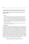
1
A500.A4
01.10.13 6:40 PM
Page 3
VARIABLE FREQUENCY DRIVES
A500 SERIES
ADVANCED INTELLIGENT CONTROL
UL
cUL
CE
Modbus plus
Device Net
Profibus DP
CC-Link
The Culmination of
Mitsubishi’s Expertise
Reaches into the Realms
of Advanced Technology
Expanding the Potential
of Inverters
Announcing the FR-A500 Series, a new line
of advanced inverters that combines Mitsubishi
Electric’s original technology with the benefits
of its vast pool of accumulated expertise.
Beginning with advanced magnetic flux vector
control, which allows high-precision operations
at ultra-low speeds, Mitsubishi has mastered
many aspects of advanced technology to equip
this series with performance of the highest
order. With their astonishing top-level
specifications, this new series opens up an
entirely new area of potential for inverters
in the 21st Century.
CONTENTS
Features
3
Model Configuration
7
Standard Specifications
8
External Dimension Diagrams
10
Terminal Connection Diagram
14
Explanation of Terminal Specifications
15
Explanation of Control Panel
16
Key Operations Using the Control Panel
17
Explanation of Parameter Unit
18
List of Parameters
19
Applications
23
Protective Functions
24
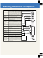
Selecting Peripherals and Options
26
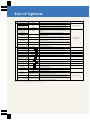
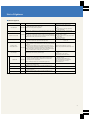
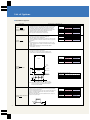
List of Options
27
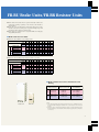
FR-BU Brake Units/FR-BR Resistor Units
32
FR-HC High-power Factor Converters
FR-RC Power Regenerating Converters
34
Points to Note when Using and
Selecting Units
36
Points to Note when Selecting
Peripherals
37
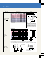
Features
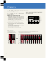
1. The Ability to Maximize Drive Performance
■ Advanced Flux Vector Control
Example of motor temperature/speed variation characteristics
(SFJR 4P 3.7kW motor). (Repeated operations at 90% usage rate,
on-line auto tuning selected)
New levels in drive performance have been achieved thanks to the
use of advanced flux vector control, an original technology
developed by Mitsubishi.
320
The units feature a RISC processor which is used for on-line auto
tuning, turning the motor quickly when starting. This allows it to
perform high-precision operations that are unaffected by motor
temperature, as well as stable high-torque operation from ultra
low speeds.
Speed control range: 1:120 (0.5~60Hz, driving mode)
Using the auto tuning function, high precision operation is
possible with motors from all over the world.
Speed (r/min)
300
240
0
10
20
30
40
50
Elapsed time (min)
60
200
100
100
Enlarged
0
50
100
150
200
Torque (%)
Torque (%)
Motor temperature
270
160
(339.2)
140
(296.8)
120
(254.4)
100
(212)
80
(169.6)
60
(127.2)
40
(84.8)
20
(42.4)
0
70
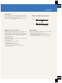
Example of speed/torque characteristics when using advanced flux vector control
(on-line tuning selected, SF-JR 4P 3.7kW motor)
200
0
-100
-100
-200
-200
(r/min)
3
Speed (no auto tuning)
280
250
Combining this function with a motor equipped with PLG
feedback improves high-precision operations still further (builtin option FR-A5AP).
* Use an inverter that is one rank higher than the motor capacity.
Speed control range: 1:1000 (driving mode)
Speed variation rate: ±0.02% (driving mode)
Zero speed holding torque: 150% (short time rating)
0
290
260
● Boost Performance even further with PLG feedback
Example of speed/torque
characteristics during low-speed
operations (SF-JR 4P 3.7kW motor)
Speed (with auto tuning)
310
Temperature (°C (°F))
● High-precision Operations without a PLG
0
6Hz
200
30Hz
400
600
800
1000
(r/min)
60Hz
1200
1400
1600
1800
2000
Features
■ Smart Driver
Uneven rotation at low speeds has been greatly improved by the
use of a smart driver (a newly developed ASIC) which directly
monitors and controls the main circuit's status.
• Uneven rotation: less than half that of a conventional Mitsubishi
inverter at 1 Hz
Example of comparative data on uneven rotation
(inverter operation frequency: 3Hz; SF-JR 4P 3.7kW motor)
FR-A500
5%
0
15%
FR-A200
0
■ High-response Current Limit
■ Expandability
Further improving the responsiveness of current detection has
reduced the occurrence of trips arising from overcurrent.
This makes it possible to deal more effectively with the momentary
large currents that occur when starting a reverse coasting motor or
when switching an MC ON and OFF on the inverter output.
Various I/Os are available, including pulse train, analog signals,
digital signals, and network connections.
• Up to three option cards can be mounted internally.
• Direct communications with a PLC is possible, e.g. Control &
Communication Link (CC-Link).
Accommodates PLC X/Y instructions for easy programming.
■ New Functions
The addition of a number of new functions has made it possible to
handle various applications.
Some examples are:
• Power failure deceleration stop function
→ Rotary cutters, etc.
• PID control → Air-conditioning, etc.
• Brake sequence function → Conveyors, etc.
• Commercial power supply inverter switch-over sequence
function → Pumps, etc.
4
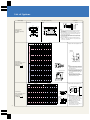
Features
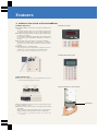
2. Achieves New Levels of User-friendliness
■ Simple Operation
FR-DU04 control panel
● The simple FR-DU04 control panel is provided as standard on all
models.
An optional extension cable can be used with the control panel.
Operational and alarm signals can also be shown with this unit.
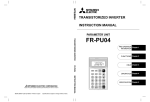
● The FR-PU04 LCD parameter unit with long-life backlight display
is available as an option.
The unit features Mitsubishi's original direct input method which
uses the ten-key pad. Eight different languages are available on
one unit.
● The parameter user group function is provided as standard.
This function facilitates control of parameters by making it
possible to select, read and write only those parameters that are
required.
● Communications is a standard feature.
The control panel can be disconnected to allow the unit to be
controlled by a personal computer via an RS-485 interface.
Note: A converter is necessary if an RS-232C interface is to be used.
FR-PU04 parameter unit (option)
■ Easy Maintenance
● The life of the cooling fan has been extended by the use of
ON/OFF control, and replacement is easier.
Simple to install/remove control terminals
● Simple installation and removal of the control terminal block
makes maintenance easier.
● Parameters can be preserved by the control panel which is fitted
as standard.
When an inverter is replaced, parameters can be set up simply by
writing previously stored parameters from the control panel.
Note: It is necessary to batch-read the parameters at the control panel
beforehand.
5
Terminal block
Features
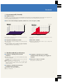
3. Environmentally Friendly
■ Soft-PWM Control
In addition to the conventional low-noise mode, Mitsubishi has developed its own original Soft-PWM control method which suppresses the
increase in acoustic noise and limits RFI noise to minimum levels similar to those of the Mitsubishi FR-Z Series inverter.
Note: The default setting is Soft-PWM control ON.
■ Motor Noise Data Example (SF-JR 4P 3.7kW motor, carrier frequency 2kHz)
With Soft-PWM
Noise level (Pa)
Without Soft-PWM
Noise level (Pa)
12k
12k
10k
10k
8k
8k
6k
6k
4k
4k
2k
2k
0
0
4
2
0
2k
4k
6k
8k
10k
4
2
Time (sec)
12k 0
Frequency (Hz)
0
2k
4k
6k
8k
Frequency (Hz)
10k
Time (sec)
12k 0
Since the frequency components are dispersed, the motor generates little metallic
noise and does not sound unpleasant.
Since the frequency components are concentrated, the motor generates a grating
metallic noise.
■ Compatible with Harmonic Limits
■ EMC Filter Available
● A compact direct current reactor (DCR) can be connected to units
of all capacities.
● It is also possible to connect a high-power factor regenerative
converter (FR-HC) that conforms to Japanese harmonic
guidelines (conversion coefficient: K5=0).
● Using the optional EMC filter makes it easy to comply with
European EMC Directives.
4. World-standard Specifications
■ Compliance with Major International
Standards
● All units comply with UL, CSA* and EN standards (low-voltage
directives) as standard.
*In order to obtain CSA standards approval at UL, the cUL mark
is applied.
● NEMA1 compliance is standard up to 22K.
● The optional FR-PUO4 parameter unit can handle eight
languages: Japanese, English, German, French, Spanish, Italian,
Swedish and Finnish
■ Compliance with 240V power supplies
(maximum 22K) and 480V power supplies as
standard
■ Sink /Source Logic is selectable
(Using jumper on terminal block).
■ Compliance with Main International
Communications Standards
● North America - DeviceNet™ Modbus plus
● Europe - Profibus DP
6
Model Configuration
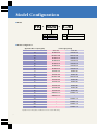
■ Model
FR - A520 - 3.7K
Type
A520
A540
Voltage class
200V class
400V class
Type
0.4K280K
Applicable Motor Capacity
Indicates capacity in kW
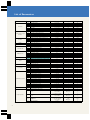
■ Model Configuration
Applicable Motor Capacity (kW)
Power Supply Voltage
200V class
400V class
0.4
FR-A520-0.4K
FR-A540-0.4K
0.75
FR-A520-0.75K
FR-A540-0.75K
1.5
FR-A520-1.5K
FR-A540-1.5K
2.2
FR-A520-2.2K
FR-A540-2.2K
3.7
FR-A520-3.7K
FR-A540-3.7K
5.5
FR-A520-5.5K
FR-A540-5.5K
7.5
FR-A520-7.5K
FR-A540-7.5K
11
FR-A520-11K
FR-A540-11K
15
FR-A520-15K
FR-A540-15K
18.5
FR-A520-18.5K
FR-A540-18.5K
22
FR-A520-22K
FR-A540-22K
30
FR-A520-30K
FR-A540-30K
37
FR-A520-37K
FR-A540-37K
45
FR-A520-45K
FR-A540-45K
55
FR-A520-55K
FR-A540-55K
75
Available soon
Available soon
90
Available soon
–
110
–
Available soon
160
–
Available soon
220
–
Available soon
280
–
Available soon
Applicable motors with capacities of 75kW and over are not covered in this catalog.
7
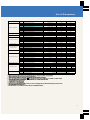
Standard Specifications
Ratings
■ 200V class
0.4K
0.75K
1.5K
2.2K
3.7K
5.5K
7.5K
11K
15K
18.5K
22K
30K
37K
45K
55K
Applicable motor capacity (kW) (Note 1)
0.4
0.75
1.5
2.2
3.7
5.5
7.5
11
15
18.5
22
30
37
45
55
(Note 2)
1.1
1.9
3.1
4.2
6.7
9.2
12.6
17.6
23.3
29
34
44
55
67
82
3
5
8
11
17.5
24
33
46
61
76
90
115
145
175
215
Type FR-A520-
Rated capacity (kVA)
Rated current (A)
Output
(Note 3)
Overload current rating
Regenerative
braking torque
Power
supply
150% for 60 sec., 200% for 0.5 sec. (Inverse time characteristics)
(Note 4)
Voltage
3-phase 200 - 220V 50Hz, 200 - 240V 60Hz
Max. value/time
3%ED
Tolerable working rate
3-phase 200 - 220V 50Hz, 200 - 230V 60Hz
100% for 5 sec.
150% for 5 sec.
20%
2%ED
(Note 5)
Continuous
(Note 5)
Rated input, AC voltage, frequency
3-phase 200 - 220V 50Hz, 200 - 240V 60Hz
3-phase 200 - 220V 50Hz, 200 - 230V 60Hz
Tolerable AC voltage fluctuation
170 - 242V 50Hz, 170 - 264V 60Hz
170 - 242V 50Hz, 170 - 253V 60Hz
± 5%
Tolerable frequency fluctuation
(Note 6)
Power facility capacity (kVA)
1.5
2.5
4.5
5.5
9
12
17
20
28
34
41
52
Cooling method
Self cooling
Approx. weight (kg (lb))
2.0
(4.4)
2.5
(5.5)
66
80
100
Open type (IP00)
Fully enclosed type (IP20, NEMA1)
Protective structure (JEM1030)
Forced cooling
3.5
(7.7)
3.5
(7.7)
3.5
(7.7)
6.0
(13.2)
6.0
(13.2)
8.0
(17.6)
13.0
(28.7)
13.0
(28.7)
13.0
(28.7)
30.0
(66.1)
40.0
(88.2)
40.0
(88.2)
50.0
(110.2)
■ 400V class
0.4K
0.75K
1.5K
2.2K
3.7K
5.5K
7.5K
11K
15K
18.5K
22K
30K
37K
45K
55K
Applicable motor capacity (kW) (Note 1)
0.4
0.75
1.5
2.2
3.7
5.5
7.5
11
15
18.5
22
30
37
45
55
(Note 2)
1.1
1.9
3
4.2
6.9
9.1
13
17.5
23.6
29
32.8
43.4
54
65
84
1.5
2.5
4
6
9
12
17
23
31
38
43
57
71
86
110
80
100
Type FR-A540-
Rated capacity (kVA)
Rated current (A)
Output
Overload current rating
(Note 3)
Voltage
(Note 4)
Regenerative
braking torque
Power
supply
150% for 60 sec., 200% for 0.5 sec. (Inverse time characteristics)
3-phase 380 - 480V 50Hz/ 60Hz
Max. value/time
100% for 5 sec.
Tolerable working rate
20%
2%ED
Rated input, AC voltage, frequency
3-phase 380 - 480V 50Hz/ 60Hz
Tolerable AC voltage fluctuation
323 - 528V 50Hz/ 60Hz
Tolerable frequency fluctuation
± 5%
Power facility capacity (kVA)
1.5
2.5
4.5
Protective structure (JEM1030)
9
12
17
20
28
34
41
52
Self cooling
3.5
(7.7)
3.5
(7.7)
66
Open type (IP00)
Fully enclosed type (IP20, NEMA1)
Cooling method
Approx. weight (kg (lb))
5.5
(Note 5)
Continuous (Note 5)
Forced cooling
3.5
(7.7)
3.5
(7.7)
3.5
(7.7)
6.0
(13.2)
6.0
(13.2)
13.0
(28.7)
13.0
(28.7)
13.0
(28.7)
13.0
(28.7)
24.0
(53.0)
35.0
(77.3)
35.0
(77.3)
36.0
(79.5)
Notes: 1. "Applicable motor capacity" refers to the maximum applicable capacity when using a 4-pole standard Mitsubishi motor.
2. The rated output capacity is 220V for the 200V class, and 440V for the 400V class.
3. The percentage given for the overload current rating indicates the ratio with respect to the inverter's rated output current. In the case of repeated use, it is essential
to wait until the inverter and the motor have cooled to below the temperature for 100% load.
4. The maximum output voltage may not exceed the power supply voltage, and can be set at any value below the power supply voltage.
5. Indicates the average torque for decelerating to a stop from 60Hz. Changes according to motor loss.
6. Power capacity differs according to the power supply impedance value (including the input reactor or wire values).
8
Standard Specifications
■ Common Specifications
Control Method
Soft-PWM control, high-carrier frequency PWM control (V/F control, advanced flux vector control selection)
Output frequency range
Control Specifications
Frequency
control resolution
0.2 to 400Hz
Analog input
0.015 Hz (Terminal No. 2 input: 12 bit/0 to 10V, 11 bit/0 to 5V; Terminal No. 1 input: 12 bit/-10 to +10V, 11 bit/-5 to +5V)
Digital input
0.01Hz
Within ±0.2% of max. output frequency (25°C (53°F)±10°C (±21.2°F))/during analog input: within 0.01% of set output frequency during digital input
Frequency precision
Voltage/frequency characteristics
Starting torque
150% at 0.5 Hz (advanced flux vector control)
Torque boost
Manual torque boost
Acceleration/deceleration time setting
DC braking
Operation Specifications
Input
signal
DC0 to 5V, 0 to 10V, 0 to ±10V, 4 to 20mA
Digital input
Input from control panel, parameter unit; BCD 3-digit or 12-digit binary (using option FR-A5AX)
Starting signal
Individual selection of forward run, reverse run; starting signal self-hold input (3-wire input) selective
Multi-speed selection
Up to 15 set speeds (each speed can be set between 0 and 400 Hz; speed can be changed via control panel or parameter unit during operation)
2nd, 3rd accel/decel time
0 to 3,600 sec. (max. of three individual accelerations/decelerations can be set)
JOG operation selection
JOG operation mode selection terminal provided (Note 1)
Current input selection
Instant cutoff of inverter output (frequency, voltage)
Error reset
Reset of protection operation hold state
Upper/lower limit frequency setting, frequency jump operation, external thermal input selection, reverse polarity operation, instantaneous power
failure restart operation, commercial power supply inverter switch-over function, forward run/reverse run prevention, slip compensation, operation
mode selection, off-line auto tuning function, online auto tuning function, PID control, programmed operation, computer link operation (RS-485)
Five types can be selected from: inverter running, frequency reached, instantaneous power failure (undervoltage), frequency detection, 2nd
frequency detection, 3rd frequency detection, in program mode operation, in PU operation, overload warning, regenerative brake pre-alarm,
electronic thermal relay pre-alarm, zero current detection, output current detection, PID lower limit, PID upper limit, PID forward run, PID reverse
run, commercial power supply-inverter switchover MC 1, 2, 3, operation ready, brake release request, fan trouble, and fin overheat re-alarm.
Open collector output.
Relay output - contactor (230 VAC 0.3A 30 VDC 0.3A); open collector - alarm code (4-bit) output
Error (inverter trip)
One type can be selected from: output frequency, motor current (constant or peak value), output voltage, frequency setting value, operation
speed, motor torque, converter output voltage (constant or peak value), regenerative brake duty, electronic thermal relay load rate, input
power, output power, load meter and motor excitation current. Pulse train output (1,440 pulse/sec./full scale) or analog output (0 to 10 VDC).
Display
For meter
Displayed on
FR-DU04
control panel or
FR-PU04
parameter unit
Additional
displays only on
FR-PU04
parameter unit
Select input of frequency setting signal 4 to 20 mA DC (terminal No. 4)
Output stop
Operation status
Operation status
Error details
Operation status
Error details
Interactive
Protective and warning functions
Ambient temperature
Environment
Operation current level setting possible (0 to 200% variable), enable/disable selection
Analog input
Operation functions
Output
signal
0 to 3,600 sec. (individual setting for acceleration/deceleration possible), linear or S-curve mode
Operation frequency (0 to 120 Hz), operation time (0 to 10 sec.), operation voltage (0 to 30%) variable
Stall prevention operation level
Frequency
setting signal
Any base frequency setting possible between 0 and 400 Hz; constant torque or variable torque pattern selection possible.
Atmosphere
Altitude and vibration
Details of errors are displayed when the protective function activates. Details of up to eight errors are saved. (Only four errors are displayed on the control panel.)
Input terminal signal status, output terminal signal status, option mounting status, terminal assignment status.
Output voltage, current, frequency and cumulative power ON time before protective function activates
Operation guide and troubleshooting with help function
Overcurrent cutoff (during acceleration, deceleration, constant speed), regenerative overvoltage cutoff, undervoltage, instantaneous power failure,
overload cutoff (electronic thermal relay), brake transistor error (Note 2), ground fault overcurrent, output short circuit, stall prevention, overload
warning, brake resistor overheating, fin overheating, fan trouble, option error, parameter error, PU disconnected number of retries exceeded, output
phase loss, CPU error, 24VDC power output short circuit, control panel power short circuit.
-l0°C (-21.2°F) to +50°C (+106°F) (no freezing) (-10°C (-21.2°F) to +40°C (+84.8°F) using fully enclosed structure specifications attachment (FR-A5CV))
Ambient humidity
Storage temperature
Select from output frequency, motor current (constant or peak value), output voltage, frequency setting value, operation speed, motor torque,
overload, converter output voltage (constant or peak value), electronic thermal relay load rate, input power, output power, load meter, motor
excitation current, cumulative power ON time, actual operation time, cumulative power, regenerative brake duty and motor load rate.
90%RH or less (no condensation)
(Note 3)
-20°C (+42.4°F) to +65°C (+137.8°F)
Indoors (no corrosive gases, flammable gases, oil mist or dust)
Max. 1,000 m (3,280.8 ft) above sea level, max. 5.8 m (19.03 ft)/s 2 {0.6G} (JIS C 0911 compliance)
Notes:
1. JOG operation is possible with the control panel and parameter unit.
2. Not provided for models FR-A520-11 K through 55K, or models FR-A540-11 K through 55K, which have no brake circuits.
3. Temperatures to which the units can be exposed for a short time, such as during transportation.
9
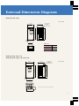
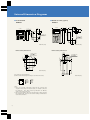
External Dimension Diagrams
■ FR-A520-0.4K, 0.75K
units: mm (inch)
110 (4.33)
D
2 (0.08)- 6 (0.24)
mounting hole
245 (9.65)
260 (10.24)
5
(0.20)
6
(0.24)
95 (3.74)
● 200V class
Inverter type
D
FR-A520-0.4K
110 (4.33)
FR-A520-0.75K
125 (4.92)
■ FR-A520-1.5K, 2.2K, 3.7K
■ FR-A540-0.4K, 0.75K, 1.5K, 2.2K, 3.7K
150 (5.91)
140 (5.51)
2 (0.08)- 6 (0.24)
mounting hole
units: mm (inch)
245 (9.65)
260 (10.24)
5
(0.20)
6
(0.24)
49.5
(1.95)
125 (4.92)
Note: FR-A540-0.4K~1.5K do not have cooling fans.
143 (5.63)
10
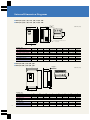
External Dimension Diagrams
■ FR-A520-5.5K, 7.5K, 11K, 15K, 18.5K, 22K
■ FR-A540-5.5K, 7.5K, 11K, 15K, 18.5K, 22K
W
D
2 (0.08)- 6 (0.24)
mounting hole
units: mm (inch)
H
H1
D1
10.5 (0.41)
W2
As viewed from direction of arrow
Note: FR-A520-5.5K-11K, FR-A540-5.5K, 7.5K
do not have slits.
C
W1
● 200V class
Inverter type
FR-A520-5.5K/7.5K
FR-A520-11K
FR-A520-15K/18.5K/22K
W
220 (8.66)
220 (8.66)
250 (9.84)
W1
195 (7.68)
195 (7.68)
230 (9.06)
W2
211 (8.31)
211 (8.31)
242 (9.53)
H
H1
260 (10.24) 245 (9.65)
300 (11.81) 285 (11.22)
400 (15.75) 380 (14.96)
D
D1
170 (6.69) 86.5 (3.41)
190 (7.48) 101.5 (4.00)
190 (7.48) 101.5 (4.00)
C
6 (0.24)
6 (0.24)
10 (0.39)
● 400V class
Inverter type
FR-A540-5.5K/7.5K
FR-A540-11K/15K/18.5K/22K
W
220 (8.66)
250 (9.84)
W1
195 (7.68)
230 (9.06)
W2
211 (8.31)
242 (9.53)
H
H1
D
D1
260 (10.24) 245 (9.65) 170 (6.69) 86.5 (3.41)
400 (15.75) 380 (14.96) 190 (7.48) 101.5 (4.00)
C
6 (0.24)
10 (0.39)
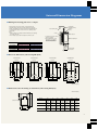
■ FR-A520-30K, 37K, 45K, 55K
■ FR-A540-30K, 37K, 45K, 55K
2 (0.08)- 6 (0.24)
mounting hole
W
units: mm (inch)
D
D1
3.2
(0.13)
H1
H
W2
As viewed from direction of arrow
C
W1
11
● 200V class
Inverter type
FR-A520-30K
FR-A520-37K /45K
FR-A520-55K
W
W1
W2
340 (13.39) 270 (10.63) 320 (12.60) 550
450 (17.72) 380 (14.96) 430 (16.93) 550
480 (18.90) 410 (16.14) 460 (18.11) 700
H
H1
(21.65) 530 (20.87)
(21.65) 525 (20.67)
(27.56) 675 (26.57)
D
195 (7.68)
250 (9.84)
250 (9.84)
D1
71.5 (2.81)
154 (6.06)
154 (6.06)
C
10 (0.39)
12 (0.47)
12 (0.47)
● 400V class
Inverter type
FR-A540-30K
FR-A540-37K /45K /55K
W
W1
W2
H
H1
340 (13.39) 270 (10.63) 320 (12.60) 550 (21.65) 530 (20.87)
450 (17.72) 380 (14.96) 430 (16.93) 550 (21.65) 525 (20.67)
D
195 (7.68)
250 (9.84)
D1
71.5 (2.81)
154 (6.06)
C
10 (0.39)
12 (0.47)
External Dimension Diagrams
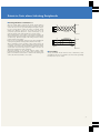
■ Making the housing plate more compact
Housing plate
When the inverter is being used inside a housing plate, the heat
generated inside the plate can be greatly reduced by projecting the
inverter's heat radiating fin outside of the plate. This mounting method is
recommended when trying to reduce the size of a completely sealed
housing plate.
Notes
1. When mounting, use mounting attachment FR-A5CN (sold separately)
(for models 1.5K~55K).
2. The fin height is greater than the height of the FR-A200 series.
Model
FR-A5CN01
FR-A5CN02
FR-A5CN03
FR-A5CN04
Compatible
200V class
FR-A520-1.5~3.7K
FR-A520-5.5K/7.5K
FR-A520-11K
FR-A520-15K~22K
FR-A5CN mounting
hardware**
(option)
Inside housing plate
Inverter
Cooling fan
*D1 dimensions from the external
dimensions diagram.
**With the FR-A5CN01, the fin
replacement cover attaches
to the mounting hardware at
the bottom of the inverter.
Heat radiating fin
inverter
400V class
FR-A540-0.4K~3.7K
FR-A540-5.5K/7.5K
—
FR-A540-11K~22K
Cooling
breeze
D1
External plate
dimensions*
■ Panel cut dimensions (when using FR-A5CN)
195 (7.68)
212 (8.35)
90
(3.54)
440 (17.32)
517 (20.35)
244 (9.61)
335 (13.19)
320 (12.60)
40 102
(1.57) (4.02)
90 (3.54)
102 (4.02)
407 (16.02)
305 (12.01)
280 (11.02)
200 (7.87)
6 (0.24)-M5
(0.20) screws
7.5
(0.30)
2.5
(0.10)
6 (0.24)-M5
(0.20) screws
195 (7.68)
212 (8.35)
• FR-A5CN04
175 (6.89)
90 (3.54)
102 (4.02)
367 (14.45)
90 (3.54)
265 (10.43)
280 (11.02)
265 (10.43)
365 (14.37)
100 (3.94)
6 (0.24)-M5
(0.20) screws
100 (3.94)
125 (4.92)
• FR-A5CN03
175 (6.89)
6 (0.24)-M5
(0.20) screws
230 (9.06)
260 (10.24)
12.5
(0.49)
• FR-A5CN02
144 (5.67)
7.5
(0.30)
• FR-A5CN01
units: mm (inch)
H4
■ Dimensions after mounting of attachment (when using FR-A5CN)
H
H2
H1
units: mm (inch)
Model
FR-A5CN01
Outside of inverter
W1
W
H3
FR-A5CN02
FR-A5CN03
FR-A5CN04
W
150
(5.91)
245
(9.65)
245
(9.65)
280
(11.02)
H
389.5
(15.33)
408.5
(16.08)
448.5
(17.66)
554
(21.81)
H1
18
(0.71)
116.5
(4.59)
116.5
(4.59)
122
(4.80)
W1
125
(4.92)
195
(7.68)
195
(7.68)
230
(9.06)
H2
370
(14.57)
370
(14.57)
410
(16.14)
530
(20.87)
H3
11.5
(0.45)
22
(0.87)
22
(0.87)
12.5
(0.49)
H4
8
(0.31)
16.5
(0.65)
16.5
(0.65)
11.5
(0.45)
12
External Dimension Diagrams
■ Parameter Unit (option)
FR-PU04
24
(0.94)
13
(0.51)
80 (3.15)
13
(0.51)
20
(0.79)
125 (4.92)
81.5 (3.21)
48 (1.89)
21.5
(0.85)
24
(0.94)
46.5 (1.83)
16.5 (0.65)
15 9.7
(0.59) (0.38)
72 (2.83)
9.7
(0.38)
15
(0.59)
20
(0.79)
72 (2.83)
18.5
(0.73)
■ Control Panel
FR-DU04
2 (0.08)- 4 (0.16)
mounting hole
5 (0.20)- 4 (0.16)
mounting hole
54 (2.13)
40 (1.57)
units: mm (inch)
Panel cutaway dimensions
16.5
(0.65)
2 (0.08)- 4 (0.16)
mounting hole
17 (0.67)
13 1.5 (0.06)
43.75
11.75 (1.72)
(0.46)
1.25
(0.05)
81.5 (3.21)
3.5
46.5 (0.14)
(1.83)
17 (0.67)
19.75
(0.78)
16.5 (0.65)
23.75
(0.94)
2 (0.08)- 4 (0.16)
mounting hole
1.5
(0.06)
Panel cutaway dimensions
units: mm (inch)
3.25
(0.13)
54
(2.13)
units: mm (inch)
PU connector pin arrangement
(main inverter unit (receptacle side), as seen from the front)
8
1
SG
P5S
3 RDA
4 SDB
SDA
RDB
7 SG
8 P5S
1
5
2
6
Notes:
1. Please do not make connections between the PU connector and
computer LAN boards, fax modem sockets, or modular connectors
for telephones. Since their electrical specifications are different,
doing so may damage the unit.
2. Pins w and i (P5S) are the power supplies for the control panel and
the parameter unit. Please do no use them during communications
via the RS-485 interface.
13
3.75
(0.15)
40
(1.57)
units: mm (inch)
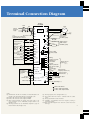
Terminal Connection Diagram
Inverter
FR-A500
NFB
Motor
MC
R
S
T
3-phase
AC power
supply
U
PU connector
(RS-485)
IM
V
W
(Note 8)
R1
S1
Short bar
(Note10)
24 VDC power supply and
external transistor common
Short bar (Note 3)
Grounding
Power factor
improvement
DC reactor
FR-BEL (option)
P1
PC
Forward run start
STF
Reverse run start
STR
P
R
(Note 1)
STOP
Start self-hold
selection
High
Multi-speed
selection
(Max. 15
speeds)
PX
PR
R
RH (Note 5)
speed
Medium
speed
Low
speed
RL
(Note 5)
A
B
C
(Note 5)
JOG
RT (Note 5)
MRS
JOG mode
Output stop
Reset
RES
AU (Note 5)
CS (Note 5)
Current input selection
Instantaneous power
failure restart selection
RUN
SU
IPF
Contact
SD input
OL
common
10E (+10V)
10 (+5V)
2
1
DC0 - 5V
2 DC0
-10V
(Note 6)
FM
5 (Analog common)
SD
Common
(Note 6)
Auxiliary input
Current input
Running
Frequency reached
Instantaneous
power failure
Overload
Open collector
output (Note 4)
(Note 10)
Frequency detection
SE Open collector output
common
Scale calibration
resistor
(Note 7)
Display meters
1/2W 10kΩ
(frequency meters, etc.)
(Note 10)
3
Error output
(Relay output)
FU
Control input signal (not for voltage input)
Frequency
potentiometer
1/2W1KΩ
High-frequency
brake resistor
FR-ABR (option)
N
RM (Note 5)
2nd acceleration/
deceleration time selection
(Note 9)
Short bar (Note 2)
(Note 1)
- ±5V Changeover
1 DC0
DC0 - ±10V
AM
5
+
-
coil type )
( Moving
1mA full scale
(+) Analog signal output
(-) (DC 0-10V)
4 (DC4 - 20mA)
Grounding (Note 8)
Frequency setting signal (analog)
Main circuit terminal
Control circuit input terminal
Control circuit output terminal
Notes:
(1) Terminals PR and PX are mounted on models FR-A520-0.4 K
through 7.5 K and models FR-A540-0.4 K through 7.5 K.
(2) Remove this short bar when using the FR-ABR.
(3) Remove this short bar when using the FR-BEL.
(4) These output terminals can output error alarm codes, or 26
types of function can be individually assigned with Pr. 190
through to 195.
(5) This input terminal can be individually assigned 23 types of
function with Pr.180 through to 186.
(6) The input signal can be changed with Pr. 73.
(7) Not required when the meter is calibrated with the control
panel.
(8) Always ground the inverter and motor.
(9) 2W1kΩ is recommended when the frequency setting is
changed frequently.
(10) This connection diagram is for when the control circuit uses
sink logic.
14
Explanation of Terminal Specifications
Terminal
symbol
Type
Main Circuit
Terminal name
Explanation
R,S,T
AC power supply input
Connected to the commercial power supply.
U,V,W
Inverter output
Connects the 3-phase squirrel cage motor.
R1,S1
Control circuit power
supply
Connected to the AC power supply terminals R and S. To hold the error display or error output, remove the short bar on the terminal
block, and input a power supply to this terminal from an external source.
P,PR
Brake resistor connection
Remove the short bar between terminals PX and PR, and connect the optional brake resistor (FR-ABR) between terminals P and PR.
P,N
Brake unit connection
Connect the optional FR-BU type brake unit or high-power factor converter (FR-HC).
P,P1
Power factor improvement
DC reactor connection
Remove the short bar between terminals P and P1, and connect the optional power factor improvement DC reactor (FR-BEL).
PR,PX (Note 1) Built-in brake circuit connection The built-in brake circuit is enabled when the short bar is connected between terminals PX and PR. (Default setting)
Grounding
This is for grounding the inverter chassis. Always ground the inverter.
STF
Forward run start
Serves as the forward run command when terminals STF-SD (Note 3) are ON. In the programmed
operation mode, serves as programmed operations start signal. (Start at ON, stop at OFF)
STR
Reverse run start
Serves as the reverse run command when terminals STR-SD (Note 3) are ON.
Start self-hold selection
The self-hold of the start signal is selected when terminals STOP-SD (Note 3) are ON.
Contact
Control Circuit, Input Signals
STOP
RH, RM, RL
Multi-speed selection
JOG
JOG mode selection
RT
Frequency setting
Analog
Open collector
Control Circuit Output Signal
The terminal function
changes according to the
input terminal function
(Note
3)
The 2nd acceleration/deceleration time is selected when terminals RT-SD
are ON. If other 2nd selection (Pr. 180
functions such as "2nd torque boost" or "2nd V/F (base frequency)" are set, these functions will be through 186).
selected when terminals RT-SD are ON.
Output stop
Inverter output stops when terminals MRS-SD (Note 3) are ON (for 20 ms or more). This is used to cut off the inverter output when
stopping the motor with a magnetic brake.
RES
Reset
This is used to cancel the hold state when the protection circuit activates. Turn ON terminals RES-SD
and then turn OFF.
AU
Current input selection
Operation is possible with the frequency setting signal 4 to 20 mA DC only when terminals AU-SD (Note 3) are ON.
CS
Instantaneous power
failure restart selection
If terminals CS-SD (Note 3) are ON, the motor will restart automatically when the power is restored.
However, to use this operation, restart must be enabled. (Restart is disabled as the default setting.)
SD
Contact input common (sink)
This is the common terminal for the terminal FM and for the contact input terminal during sink logic. It is insulated from the control
circuit's common terminals.
PC
24 VDC power supply,
external transistor
common and contact
input common (source)
When connecting a transistor output (open collector output) such as a programmable logic controller (PLC), malfunctions caused by
supplied current can be prevented by connecting the external power common for the transistor output to this terminal. It is possible
to use 24 VDC 0.l A as the power supply. When source logic is selected, this is the common terminal for the contact input terminal.
10
Communications
The multi-speed can be selected with a combination of ON/OFF commands between the terminals RH,
RM and RL-SD (Note 3) .
JOG operation is selected when terminals JOG-SD (Note 3) are ON, and JOG operation can be started
with the start signal (STF or STR), or control panel.
MRS
10E
Contact
2nd acceleration/
deceleration time
selection
Frequency setting power
supply
10 VDC tolerable load current 10 mA
5 VDC tolerable load current 10 mA
(Note 3)
for 0.1 sec., or more,
The terminal function
changes according to the
input terminal function
selection (Pr. 180
through 186).
When connecting a potentiometer at the default setting, connect to terminal 10. To connect to
terminal 10E, change the input specifications for terminal 2.
2
Frequency setting
(voltage)
When 0 to 5 VDC (or 0 to 10 V) is input, the max. output frequency is reached at 5 V (10 V). The input and output are proportional.
The inputs 0 to 5 VDC (default setting) and 0 to 10 VDC are changed using Pr. 73. Input resistance 10 Ω max., tolerable voltage 20V.
4
Frequency setting
When 4 to 20 mA DC is input, the max. output frequency is reached at 20 mA. The input and output are proportional. This input
signal is enabled only when terminals AU-SD (Note 3) are ON. The input resistance 250 Ω max., tolerable current 30 mA
1
Auxiliary frequency
setting
When 0 to ±5 VDC or 0 to ±10 V is input, this signal is added to the terminal 2 or 4 frequency setting signal. The inputs 0 to ±5 VDC
or 0 to ±10 V (default setting) are changed using Pr 73. Input resistance 10 Ω max., tolerable voltage ±20V
5
Frequency setting
common
This is the common terminal for the frequency setting signal (terminal 2, 1 or 4) and analog output terminal AM. This terminal is not
insulated from the control circuit's common terminals. Do not ground this common.
A,B,C
Error output
This is a 1c relay output that indicates that the inverter's protection circuit has functioned and the output has
stopped. 200 VAC 0.3 A, 30 VDC 0.3A. When an error occurs, there is non-continuity between B-C (continuity
between A-C); in normal operations, there is continuity between B-C (non-continuity between A-C).
RUN
Inverter running
SU
Frequency reached
OL
Overload warning
IPF
Instantaneous power
failure
FU
Frequency detection
L level is output when the inverter output frequency is higher than the starting frequency (default: 0.5 Hz, The terminal function
changeable), and the H level is set when stopped or during DC braking (Note 2). Tolerable load: 24 VDC 0.l A
changes according to the
The L level is set when the output frequency is within ±10% (default, changeable) of the set frequency, and output terminal function
selection (Pr. 190 to
the H level is set during acceleration/deceleration and when stopped (Note 2). Tolerable load: 24V DC 0.lA
195).
The L level is output when stall prevention is activated by the stall prevention function, and the H level is set when stall prevention is
canceled (Note2). Tolerable load: 24 VDC 0.l A
The L level is output when the instantaneous power failure or undervoltage protection has functioned
(Note 2). Tolerable load: 24 VDC 0.1 A
The L level is output when the output frequency is higher than the set detection frequency, and the H level is output when it
is lower (Note 2). Tolerable load: 24 VDC 0.1 A
SE
Open collector output common This is the common terminal for the terminals RUN, SU, OL, 1PF and FU. It is insulated from the control circuit's common terminals.
Pulse
FM
For display meter
Analog
AM
Analog signal output
RS485
–
PU connector
One of 16 monitor items, such as output Default output item: frequency; tolerable load current 1 mA l,440 pulse/sec. at 60 Hz
frequency, is selected and output. The
output signal is proportional to the size
Default output item: frequency; output signal 0 to 10 VDC, tolerable load current 1 mA
of each monitor item.
RS-485 communications can be carried out using the control panel connector.
Compliance standards: EIA Standard RS-485. Transmission format: multidrop link method. Communication rate: max. 19200 baud.
Total length: 500 m (1,640.4 ft).
Notes:
1. Terminals PR and PX are mounted on models FR-A520-0.4 K through 7.5 K, and on models FR-A540-0.4 K through 7.5 K.
2. The L level indicates when the open connector output transistor turns ON (continuity state). The H level indicates when it is in the OFF state (non-continuity state).
3. When using source logic, the terminal PC will be the common terminal, not SD.
15
If terminals STF and
STR-SD (Note 3) are ON
simultaneously, they
serve as the stop
command.
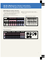
Explanation of Control Panel
Control Panel FR-DU04
External View
4-digit LED monitor
Frequency
Unit indicators:
Current
Voltage
Monitor, External operation,
PU operation
Mode display
Reverse, Forward
Arrow keys
[UP/DOWN keys]
Operation controls
Reverse key
Forward key
MODE key
STOP & RESET key
SET key
Note: The Control Panel is standard equipment, and may be detached.
■ External Operation
When a Start or Frequency instruction is sent from the control
terminal.
CONTROL PANEL
Hz
A
V
FR-DU04
MON
EXT
REV
The monitor display during forward
run at 60Hz.
■ PU Operation
(PU: control panel, parameter unit)
When the unit is operated from the control panel.
Connection example
Inverter
PU
FWD
Power supply
U
R
S
T
V
Control
panel
Motor
IM
W
Connection example
Inverter
Motor
R
Power supply
Frequency
potentiometer
U
S
V
T
W
IM
STF
STR
SD
10
2
5
■ Simultaneous PU/External Operations
Simultaneous control panel (FR-DU04), parameter unit (FR-PU04)
and external operations is possible by setting Pr. 79.
(1) Press [MODE] key
FR-DU04
MON
(2) Set the desired operating frequency
using the arrow keys
eg. In the case of 60Hz, press
(or
) [SET]
FR-DU04
(3) Press [FWD] (or [REV]) key.
The motor starts.
FR-DU04
MON
MON
(4) Press [STOP] key. The motor stops.
FR-DU04
MON
CONTROL PANEL
Hz
A
V
EXT
REV
PU
FWD
CONTROL PANEL
Hz
A
V
EXT
REV
PU
FWD
CONTROL PANEL
Hz
A
V
EXT
REV
PU
FWD
CONTROL PANEL
Hz
A
V
EXT
REV
PU
FWD
16
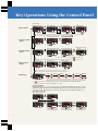
Key Operations Using the Control Panel
(at power ON)
● Frequency monitor
FR-DU04
● Monitor Display
MON
CONTROL PANEL
Hz
A
V
EXT
REV
PU
FWD
● Current monitor
SET
FR-DU04
MON
SET
CONTROL PANEL
Hz
A
V
EXT
REV
PU
FWD
● Alarm monitor
● Voltage monitor
FR-DU04
SET
MON
SET
SET
CONTROL PANEL
Hz
A
V
EXT
REV
PU
FWD
MON
SET
❊1
No alarm
MODE
FR-DU04
● Frequency Setting
Display
● Write frequency
setting to memory
● Change frequency setting
MON
FR-DU04
CONTROL PANEL
Hz
A
V
EXT
REV
PU
FWD
MON
CONTROL PANEL
Hz
A
V
EXT
REV
SET
MON
FR-DU04
PU
FWD
MON
● Change parameter number
FR-DU04
FR-DU04
CONTROL PANEL
Hz
A
V
EXT
REV
PU
FWD
MON
CONTROL PANEL
Hz
A
V
EXT
REV
CONTROL PANEL
Hz
A
V
EXT
REV
PU
FWD
SET
● Write value setting to
memory
FR-DU04
MON
Use
CONTROL PANEL
Hz
A
V
EXT
REV
PU
FWD
SET
FR-DU04
Press for
approximately
1.5 seconds
MON
CONTROL PANEL
Hz
A
V
EXT
REV
PU
FWD
to change value setting
SET
● External
operation
MON
SET
● Change value setting
PU
FWD
Use
to change
parameter number
FR-DU04
PU
FWD
MODE
MODE
● Operation Mode
Display
EXT
REV
Use
to change
frequency setting
MODE
● Parameter Setting
Display
CONTROL PANEL
Hz
A
V
❊1
SET
❊2
FR-DU04
Alarm
MODE
● PU operation
FR-DU04
CONTROL PANEL
Hz
A
V
EXT
REV
PU
FWD
MON
● JOG operation
CONTROL PANEL
Hz
A
V
EXT
REV
FR-DU04
PU
FWD
MON
CONTROL PANEL
Hz
A
V
EXT
REV
PU
FWD
MODE
FR-DU04
● Help Display
MODE
MON
CONTROL PANEL
Hz
A
V
EXT
REV
Alarm history
Alarm history
clear
Parameter
clear
Read software
version
User clear
PU
FWD
❊1
If
❊2
During external operations, the frequency setting display does not appear.
SET
All clear
is pressed continuously for approximately 1.5 seconds, the current display switches to the initial power ON display.
Copying Parameters
Parameter settings can be copied to another inverter (excluding non-FR-A500 series inverters) by using
the FR-DU04 operation panel or the FR-PU04 parameter unit. First, all of the parameters on the source
inverter are read, the operation panel is connected to the target inverter, and all of the parameters are
then written to the inverter.
● Parameter setting screen
FR-DU04
MON
FR-DU04
MON
FR-DU04
CONTROL PANEL
Hz
A
V
EXT
REV
PU
FWD
CONTROL PANEL
Hz
A
V
EXT
REV
PU
FWD
MON
SET
FR-DU04
MON
CONTROL PANEL
Hz
A
V
EXT
REV
PU
FWD
CONTROL PANEL
Hz
A
V
EXT
REV
PU
FWD
Press the SET key for
approximately 1.5 seconds
to read all of the parameters.
17
FR-DU04
MON
CONTROL PANEL
Hz
A
V
EXT
REV
PU
FWD
Press the SET key for
approximately 1.5 seconds
to write all of the parameters.
FR-DU04
MON
CONTROL PANEL
Hz
A
V
EXT
REV
PU
FWD
Press the SET key for
approximately 1.5 seconds
to check the parameters.
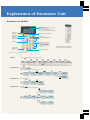
Explanation of Parameter Unit
Parameter Unit FR-PU04
Monitor screen
● Wide backlit LCD (13 characters x 4 line display)
● Interactive parameter setting
● Help function, troubleshooting guidance
● 21 types of monitor (frequency, current, voltage, etc.)
Monitor mode
select key
Operation mode selection key
Setting mode
select key
Escape key
Keys for changing frequency
HELP mode
select key
The FR-PU04
attached to
the main
inverter unit
SHIFT key
Operation instruction keys
● Used when issuing Forward,
Reverse and STOP instructions
(STOP key issues RESET
instruction when an alarm is
generated)
Function and
number keys
(0~9)
Operating the parameter unit is basically the
same as operating the earlier FR-PU02E unit.
READ and WRITE keys
Note: The Parameter Unit is optional equipment.
● Monitor:
Press the
SHIFT
key repeatedly to call up 5 types of monitor
SHIFT
Monitor
mode
Note: If
● Parameter Set:
Select
menu
WRITE
SHIFT
SHIFT
Frequency
monitor
Current
monitor
Note
Note
SHIFT
SHIFT
SHIFT
Voltage
monitor
Alarm
History
Note
Note
SHIFT
SHIFT
Other
selection monitor
Others
is pressed during monitoring, the unit is set to show the initial monitor display after power ON and inverter set, or monitor mode select.
Selected using the SET key
Enter the parameter setting value
Eg. Set Parameter 8 (deceleration time) setting to 180 seconds:
•
READ
8
SET
Enter parameter
number
Setting mode
WRITE
1 8 0
Displays
parameters
current value
Displays new
value entered
SHIFT
Displays current
value of next
parameter
Parameter
accepted
Number key
● Parameter List
3 value
monitor
(Hz, A, V)
•
READ
Select using
SET
key
•
READ
HELP
SET
Displays value
of parameter
entered
Setting mode
Parameter
Information
Displayed
Parameter
list display
(i.e. Pr.0 set display)
● All Operations
Select using SET key
Perform READ, WRITE, CHECK for all parameters
•
READ
All Pr.s reading
Reading
completed
All Pr.s writing
Writing
completed
Verifying
parameters
Verification
complete
WRITE
SET
Setting mode
Parameter
copy options
18
List of Parameters
Function
Basic functions
Standard operation functions
Output terminal functions
2nd functions
Display functions
Restart
Supplementary functions
19
Pr. No.
Name
Setting range
Minimum setting
Default setting
0 - 30%
0.1%
6%/4%/3%/2%(Note 1)
Maximum frequency
0 - 120Hz
0.01Hz
120Hz
Minimum frequency
0 -120Hz
0.01Hz
0Hz
3
Base frequency
0 - 400Hz
0.01Hz
60Hz
4
Multi-speed setting (high speed)
0 - 400Hz
0.01Hz
60Hz
5
Mult-speed setting (middle speed)
0 - 400Hz
0.01Hz
30Hz
6
Mult-speed setting (low speed)
0 - 400Hz
0.01Hz
10Hz
7
Acceleration time
0 - 3600 sec./0 - 360 sec.
0.1 sec./0.01 sec.
5 sec./15 sec. (Note 3)
8
Deceleration time
0 - 3600 sec./0 - 360 sec.
0.1 sec./0.01 sec.
5 sec./15 sec. (Note 3)
9
Electronic thermal O/L relay
0 - 500A
0.01A
Rated output current
0
Torque boost
1
2
(Note 2)
10
DC injection brake operation frequency
0 - 120Hz, 9999
0.01Hz
3Hz
11
DC injection brake operation time
0 - 10 sec., 8888
0.1 sec.
0.5 sec.
12
DC injection brake voltage
0 - 30%
0.1%
4%/2%(Note 3)
13
Starting frequency
0 - 60Hz
0.01Hz
0.5Hz
14
Load pattern selection (Note 2)
0-5
1
0
15
JOG frequency
0 - 400Hz
0.01Hz
5Hz
16
JOG acceleration/deceleration time
0 - 3600 sec./0 - 360 sec.
0.1 sec./0.01 sec.
0.5 sec.
17
MRS input selection
0, 2
1
0
18
High speed maximum frequency
120 - 400Hz
0.01Hz
120Hz
19
Base frequency voltage (Note 2)
20
Acceleration/deceleration reference frequency
0 - 1000V, 8888, 9999
0.1V
9999
0 - 400Hz
0.01Hz
60Hz
21
Acceleration/deceleration time increments
22
Stall prevention operation level
23
Stall prevention operation at double speed
0 - 200%, 9999
0.1%
9999
24
Multi-speed setting (4 speed)
0 - 400Hz, 9999
0.01Hz
9999
25
Multi-speed setting (5 speed)
0 - 400Hz, 9999
0.01Hz
9999
26
Multi-speed setting (6 speed)
0 - 400Hz, 9999
0.01Hz
9999
27
Multi-speed setting (7 speed)
0 - 400Hz, 9999
0.01Hz
9999
28
Multi-speed input compensation
0, 1
1
0
29
Acceleration/deceleration pattern
0, 1, 2, 3
1
0
30
Regenerative function selection
0, 1, 2
1
0
31
Frequency jump 1A
0 - 400Hz, 9999
0.01Hz
9999
32
Frequency jump 1B
0 - 400Hz, 9999
0.01Hz
9999
33
Frequency jump 2A
0 - 400Hz, 9999
0.01Hz
9999
34
Frequency jump 2B
0 - 400Hz, 9999
0.01Hz
9999
35
Frequency jump 3A
0 - 400Hz, 9999
0.01Hz
9999
36
Frequency jump 3B
0 - 400Hz, 9999
0.01Hz
9999
37
Speed display
0, 1 - 9998
1
0
41
Up to frequency sensitivity
0 - 100%
0.1%
10%
42
Output frequency defection
43
Output frequency defection during reverse rotation
44
2nd acceleration/deceleration time
45
2nd deceleration time
46
2nd torque boost (Note 2)
47
2nd V/F (base frequency) (Note 2)
0, 1
1
0
0 - 200%, 9999
0.1%
150%
0 - 400Hz
0.01Hz
6Hz
0 - 400Hz, 9999
0.01Hz
9999
0 - 3600 sec./0 - 360 sec.
0.1 sec./0.01 sec.
5 sec.
0 - 3600 sec./0 - 360 sec., 9999
0.1 sec./0.01 sec.
9999
0 - 30%, 9999
0.1%
9999
0 - 400Hz, 9999
0.01Hz
9999
150%
48
2nd stall prevention operation current (Note 12)
0 - 200%
0.1%
49
2nd stall prevention operation frequency (Note 12)
0 - 400Hz, 9999
0.01Hz
0
50
2nd output frequency detection
0 - 400Hz
0.01Hz
30Hz
52
DU/PU main display data selection
1
0
53
Parameter for FR-PU04
54
FM terminal function selection
1 - 3, 5 - 14, 17, 18, 21
1
1
55
Frequency monitor reference
0 - 400Hz
0.01Hz
60Hz
56
Current monitor reference
0 - 500A
0.01A
Rated output current
57
Restart coasting time
0, 0.1 - 5 sec., 9999
0.1 sec.
9999
58
Restart cushion time
0 - 60 sec.
0.1 sec.
1.0 sec.
59
Remote setting function selection
0, 1, 2
1
0
0 - 20, 22, 23, 24, 25, 100
Refer the instruction manual for the detail.
List of Parameters
Function
Operation selection functions
Motor constants
VF 5 points adjustable
3rd functions
Communications functions
Pr. No.
Setting range
Minimum setting
60
Intelligent mode selection (Note 12)
Name
0-8
1
0
65
Retry selection
0-5
1
0
66
Stall prevention operation reduction starting frequency (Note 12)
60Hz
67
Number of retries at alarm occurrence
68
Retry waiting time
69
Retry count display ensure
70
Special regenerative brake duty
Default setting
0 - 400Hz
0.01Hz
0 - 10, 101 - 110
1
0
0 - 10 sec.
0.1 sec.
1 sec.
0
---
0
0 - 15%/0 - 30%/0%(Note 5)
0.1%
0%
0 - 8, 13 - 18, 20, 23, 24
1
0
0 - 15
1
2
0 - 5, 10 - 15
1
1
0-8
1
1
0 - 3, 14 - 17
1
14
0, 1, 2, 3
1
0
71
Applied motor (Note 12)
72
PWM frequency selection
73
0 - 5V, 0 - 10V selection
74
Filter time constant selection
75
Reset selection/PU disconnected/PU
76
Alarm code output selection
77
Parameter write disable selection
0, 1, 2
1
0
78
Reverse rotation prevention selection
0, 1, 2
1
0
79
Operation mode selection (Note 12)
0-8
1
0
80
Motor capacity (Note 12)
0.4 - 55kW, 9999
0.01kW
9999
9999
81
Number of motor poles (Note 12)
2, 4, 6, 12, 14, 16, 9999
1
82
Motor excitation current (Note 12)
0 - 9999
1
9999
83
Rated motor voltage (Note 12)
0 - 1000V
0.1V
200V (Note 6)
84
Rated motor frequency (Note 12)
50 - 120Hz
0.01Hz
60Hz
89
Speed control gain (Note 10)
0 - 1000.0%
0.1%
100%
90
Motor constant (R1) (Note 10)
(Note 10)
(Note 10)
9999
91
Motor constant (R2) (Note 10)
(Note 10)
(Note 10)
9999
92
Motor constant (L1)
(Note 10)
(Note 10)
(Note 10)
9999
93
Motor constant (L2) (Note 10)
(Note 10)
(Note 10)
9999
94
Motor constant (X) (Note 10)
(Note 10)
(Note 10)
9999
95
Online auto-tuning selection (Note 12)
0, 1
1
0
96
Auto-tuning setting/status (Note 12)
0, 1, 101
1
0
0 - 400Hz, 9999
0.01Hz
9999
0 - 1000V
0.1V
0
0 - 400Hz, 9999
0.01Hz
9999
100
V/F1 (1st frequency) (Note 2, 12)
101
V/F1 (1st frequency voltage)
102
V/F2 (2nd frequency) (Note 2, 12)
103
V/F2 (2nd frequency voltage) (Note 2, 12)
104
V/F3 (3rd frequency) (Note 2, 12)
105
V/F3 (3rd frequency voltage)(Note 2, 12)
106
V/F4 (4th frequency)(Note 2, 12)
107
V/F4 (4th frequency voltage) (Note 2, 12)
108
V/F5 (5th frequency) (Note 2, 12)
109
V/F5 (5th frequency voltage)(Note 2, 12)
0 - 1000V
0.1V
0
110
3rd acceleration/ deceleration time
0 - 3600/0 - 360 sec., 9999
0.1 sec./0.01 sec.
9999
111
3rd deceleration time
0 - 3600/0 - 360 sec., 9999
0.1 sec./0.01 sec.
9999
112
3rd torque boost (Note 2)
0 - 30.0%, 9999
0.1%
9999
113
3rd V/F (base frequency) (Note 2)
0 - 400Hz, 9999
0.01Hz
9999
114
3rd stall prevention operation current
0 - 200%
0.1%
150%
115
3rd stall prevention operation frequency
116
3rd output frequency detection
117
Station number
118
Communication speed
119
Stop bit length/data length
120
Parity check presence/absence
0, 1, 2
1
2
121
Number of communication retries
0 - 10, 9999
1
1
122
Communication check time interval
0, 0.1 - 999.8 sec., 9999
0.1
0
123
Wait time setting
0 - 150ms, 9999
10ms
9999
124
CR/LF absence/presence selection
0, 1, 2
1
1
(Note 2, 12)
0 - 1000V
0.1V
0
0 - 400Hz, 9999
0.01Hz
9999
0 - 1000V
0.1V
0
0 - 400Hz, 9999
0.01Hz
9999
0 - 1000V
0.1V
0
0 - 400Hz, 9999
0.01Hz
9999
0 - 400Hz
0.01Hz
0
0 - 400Hz, 9999
0.01Hz
9999
0 - 31
1
0
48, 96, 192
1
192
0,1 (data length 8)
10, 11 (data length 7)
1
1
20
List of Parameters
Function
PID control
Commercial power supply
switchover
Pr. No.
Display
Supplementary functions
Current detection
Auxiliary functions
Supplementary functions
Restart
Initial monitor
User functions
Terminal function selection
Supplementary functions
Program operations
21
Setting range
Minimum setting
10, 11, 20, 21
---
Default setting
10
0.1 - 1000%, 9999
0.1%
100%
0.1 - 3600sec., 9999
0.1sec.
1 sec.
0 - 100%, 9999
0.1%
9999
0 - 100%, 9999
0.1%
9999
0 - 100%
0.01%
0%
0.01 - 10.00sec., 9999
0.01 sec.
9999
PID action selection
129
PID proportional band
130
PID integral time
131
Upper limit
132
Lower limit
133
PID action set point for PU operation
134
PID differential time
135
Commercial power supply switchover sequence output
terminal selection (Note 12)
0, 1
1
0
136
MC switchover interlock time (Note 12)
0 - 100.0sec.
0.1 sec.
1.0 sec.
137
Start waiting time (Note 12)
0 - 100.0sec.
0.1 sec.
0.5 sec.
138
Commercial power supply-inverter switchover selection
at alarm occurrence (Note 12)
Automatic inverter-commercial power supply switch-over
selection at alarm occurrence
0, 1
1
0
0 - 60.00Hz, 9999
0.01Hz
9999
139
Backlash
Name
128
0 - 400Hz
0.01Hz
1.00Hz
0 - 360 sec.
0.1 sec.
0.5 sec.
140
Backlash acceleration stopping frequency (Note 11)
141
Backlash acceleration stopping time (Note 11)
142
Backlash deceleration stopping frequency (Note 11)
0 - 400Hz
0.01Hz
1.00Hz
143
Backlash deceleration stopping time (Note 11)
0 - 360%
0.1 sec.
0.5 sec.
144
Speed setting switchover
148
Stall prevention level at 0 V input
0, 2, 4, 6, 8, 10, 102, 104, 106, 108, 110
1
4
0 - 200%
0.1%
150%
149
Stall prevention level at 10 V input
0 - 200%
0.1%
200%
150
Output current detection level
0 - 200%
0.1%
150%
151
Output current detection period
0 - 10 sec.
0.1 sec.
0
152
Zero current detection level
0 - 200.0%
0.1%
5.0%
153
Zero current detection period
0 - 1 sec.
0.01 sec.
0.5 sec.
154
Voltage reduction selection during stall prevention operation
0, 1
1
1
155
RT activated condition
0, 10
1
0
156
Stall prevention operation selection
157
OL signal waiting time
158
AM terminal function selection
160
User group read selection
162
Automatic restart after instantaneous failure selection
163
First cushion time for restart
164
First cushion voltage for restart
0 - 100%
0.1%
0%
165
Restart stall prevention operation level
0 - 200%
0.1%
150%
170
Watt-hour meter clear
0
---
0
171
Actual operation hour meter clear
0
---
0
173
User group 1 registration
174
User group 1 deletion
0 - 31, 100
1
0
0 - 25 sec., 9999
0.1 sec.
0
1 - 3, 5 - 14, 17, 18, 21
1
1
0, 1, 10, 11
1
0
0, 1
1
0
0 - 20 sec.
0.1 sec.
0 sec.
0 - 999
1
0
0 - 999, 9999
1
0
0
175
User group 2 registration
0 - 999
1
176
User group 2 deletion
0 - 999, 9999
1
0
180
RL terminal function selection
0 - 99, 9999
1
0
181
RM terminal function selection
0 - 99, 9999
1
1
182
RH terminal function selection
0 - 99, 9999
1
2
183
RT terminal function selection
0 - 99, 9999
1
3
184
AU terminal function selection
0 - 99, 9999
1
4
185
JOG terminal function selection
0 - 99, 9999
1
5
186
CS terminal function selection
0 - 99, 9999
1
6
190
RUN terminal function selection
0 - 199, 9999
1
0
191
SU terminal function selection
0 - 199, 9999
1
1
192
IPF terminal function selection
0 - 199, 9999
1
2
193
OL terminal function selection
0 - 199, 9999
1
3
194
FU terminal function selection
0 - 199, 9999
1
4
195
A.B.C terminal function selection
0 - 199, 9999
1
99
199
User initial value setting
0 - 999, 9999
1
0
200
Program minute/second selection
0-3
1
0
1
0.1 Hz
Min. or sec.
0
9999
0
201
Program set 1
1 - 10
0 - 2: direction of rotation
0 - 400, 9999: frequency
0 - 99, 59: time
211
Program set 2
11 - 20
0 - 2: direction of rotation
0 - 400, 9999: frequency
0 - 99, 59: time
1
0.1 Hz
Min. or sec.
0
9999
0
221
Program set 3
21 - 30
0 - 2: direction of rotation
0 - 400, 9999: frequency
0 - 99, 59: time
1
0.1 Hz
Min. or sec.
0
9999
0
231
Time-of-day setting
0 - 99.59
---
0
List of Parameters
Function
Multi-speed operations
Auxiliary functions
Stop selection functions
Power failure stop functions
Function selection
Load torque high speed
frequency control
Stop on contact control
Brake sequence functions
Supplementary functions
Calibration functions
Supplementary functions
Pr. No.
Setting range
Minimum setting
Default setting
232
Multi-speed setting (speed 8)
Name
0 - 400Hz, 9999
0.01Hz
9999
233
Multi-speed setting (speed 9)
0 - 400Hz, 9999
0.01Hz
9999
234
Multi-speed setting (speed 10)
0 - 400Hz, 9999
0.01Hz
9999
235
Multi-speed setting (speed 11)
0 - 400Hz, 9999
0.01Hz
9999
236
Multi-speed setting (speed 12)
0 - 400Hz, 9999
0.01Hz
9999
237
Multi-speed setting (speed 13)
0 - 400Hz, 9999
0.01Hz
9999
238
Multi-speed setting (speed 14)
0 - 400Hz, 9999
0.01Hz
9999
239
Multi-speed setting (speed 15)
0 - 400Hz, 9999
0.01Hz
9999
240
Soft-PWM setting
0, 1
1
1
244
Cooling fan operation selection
0, 1
1
0
250
Stop selection time
0 - 100 sec., 9999
0.1sec.
9999
261
Power failure stop selection
0, 1
1
0
262
Subtraction frequency at deceleration start
0 - 20Hz
0.01Hz
3Hz
263
Subtraction starting frequency
0 - 120Hz, 9999
0.01Hz
60Hz
264
Power failure deceleration time 1
0 - 3600/0 - 360 sec.
0.1sec./0.01sec.
5sec.
265
Power failure deceleration time 2
0 - 3600/0 - 360 sec., 9999
0.1sec./0.01sec.
9999
266
Power failure deceleration time switchover frequency
0 - 400Hz
0.01Hz
60Hz
270
Stop on contact /load torque high speed frequency control selection
0, 1, 2, 3
1
0
271
High speed setting maximum current
0 - 200%
0.1%
50%
272
Medium speed setting minimum current
273
Current averaging range
274
Current averaging filter time constant
275
Stop on contact exciting current low-speed multiplying factor (Note 9)
0 - 200%
0.1%
100%
0 - 400Hz, 9999
0.01Hz
9999
1 - 4000
1
16
1 - 1000%, 9999
1%
9999
9999
276
Stop on contact PWM carrier frequency (Note 9)
0 - 15, 9999
1
278
Brake opening frequency (Note 7)
0 - 30Hz
0.01Hz
3Hz
279
Brake opening current (Note 7)
0 - 200%
0.1%
130%
280
Brake opening current detection time (Note 7)
0 - 2 sec.
0.1 sec.
0.3 sec.
281
Brake operation time at start (Note 7)
0 - 5 sec.
0.1 sec.
0.3 sec.
282
Brake closing frequency (Note 7)
0 - 30Hz
0.01Hz
6Hz
283
Brake operation time at stop (Note 7)
0 - 5 sec.
0.1 sec.
0.3 sec.
284
Deceleration detection function selection (Note 7)
285
Over-speed detection frequency
300~
Parameters for inboard options
900
FM terminal calibration
---
901
AM terminal calibration
---
902
Frequency setting voltage bias
0 - 10V
0 - 60Hz
0.01Hz
0V
0Hz
903
Frequency setting voltage gain
0 - 10V
1 - 400Hz
0.01Hz
5V
60H
904
Frequency setting current bias
0 - 20mA
0 - 60Hz
0.01Hz
4mA
0Hz
905
Frequency setting current gain
0 - 20mA
1 - 400Hz
0.01Hz
20mA
60H
990
Buzzer control
991
Parameter for FR-PU04
0, 1
1
0
0 - 30Hz, 9999
0.01Hz
9999
Refer the option instruction manual for details.
0, 1
-----
1
1
Refer the FR-PU04 instruction manual for details.
22
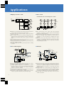
Applications
■ High-speed Crane or Lift
■ Line control
< Intermediate axis control using draw control >
High-power factor converter
Power
supply
NFB
Accessories
MC
Inverter
FR-A500
Main unit
Elevation
motor
B
Inverter
FR-A500
✕
✕
✕
✕
✕
✕
✕
✕
✕
✕
Mechanical
brakes
Feed roll
Drive roll
Travel
motor
IM
IM
IM
IM
IM
FR-A500
FR-A500
FR-A500
FR-A500
FR-A500
B
Fork
motor
Inverter
FR-A500
Ratio
setting
Power supply
B
NFB
MC
● Thanks to the wide-range speed control, high-speed operation is
possible without any decline in stopping precision.
● A brake unit is not required because a power regeneration
function is provided.
● Since elevation and travel are performed simultaneously, the
high-power factor converter should be selected according to the
capacity of the elevation motor plus the capacity of the travel
motor.
● The mechanical brake power supply is connected to the power
supply of the high-power factor converter.
● The mechanical brakes can be applied with optimal timing using
the brake sequence function.
● The large starting torque allows powerful performance in lifting
operations.
● Since advanced flux vector control offers high operational
precision, it is possible to alter the speed of each roll slightly
during draw control operations.
● Driving the rear stage rolls at slightly higher speeds than the front
stage rolls allowing stable operation in which tension is
maintained at a rate that matches the elongation rate of the
material.
● When the on-line auto tuning function is selected, the motor
constants are automatically tuned each time the motor starts,
eliminating speed variations caused by temperature fluctuations
and providing stable control.
■ Air-conditioning Fan
■ Extruder
NFB
MC1
Inverter
MC3
Pull-off roller
Power
supply
Airflow
rate
setting
Pull-off
motor
FR-A500
Vinyl bag
Materials
IM2
Reduction
gears
MC2
Pressure conveyor
Airflow
Duct
Blower
Motor
Chill source (chiller)
Heat source (heat pump or boiler)
Heat
exchanger
Hot/cold
water
Air
Air filter
Reduction
gears
Reduction
gears
Wind-up
motor
Belt
Extrusion
motor
IM1
Air
IM
PLG
FRA500
Inverter
Extruder
Inverter
IM3
Power
NFB supply NFB
FRA500
MC
MC
FRA500
Inverter
MC NFB
Frequency potentiometer
Air handling unit
● Because of the PID control function built into the inverter,
constant temperature control operation is possible.
● MCl-MC3 operation timing can be controlled with optimum
precision using the inverter's built-in commercial power supply
switchover sequence function. The external switchover
sequence circuit is also simplified.
● An electromechanical interlock that prevents MC2 and MC3 from
being turned ON simultaneously is required.
● The inverter controls temperature constantly during operation,
creating a pleasant environment and conserving energy.
23
● The frequencies for the two inverters used for extrusion and pulloff can be set with one frequency potentiometer. The ratio
between the operational frequencies of the two inverters is
adjusted for the bias and gain (Pr. 902 and 903) of the input
frequency signal.
● Advanced flux vector control (on-line auto tuning) makes it
possible to carry out operations with minimal speed fluctuation.
As a result, extrusion pressure can be accurately controlled
according to the differences in the materials being extruded.
● Using a PLG on the wind-up motor allows even more precise
control of operations.
Protective Functions
Except for the motor's electronic thermal relay, the following functions are provided for the protection of the inverter itself, but they may
also function when the inverter breaks down.
Function name
Description
When the inverter output current exceeds the rated current by more than approximately
200% during acceleration/deceleration or at constant speed, the protective circuit activates,
halting inverter output.
Over-current cut-off
Regenerative overvoltage
cut-off
If the DC voltage in the inverter's internal main circuit exceeds the rated value as a result of
regenerative energy generated through motor braking during acceleration/deceleration or at
constant speed, the protective circuit activates, halting inverter output. There are also cases
where it is activated by surge voltage generated in the power supply system.
Display
Accelerating
E.OC1
Constant speed
E.OC2
Decelerating
E.OC3
Accelerating
E.OV1
Constant speed
E.OV2
Decelerating
E.OV3
Type (Note3)
Major
Minor
fault
fault
●
●
Motor
The electronic thermal relay inside the inverter detects motor overheating resulting from overloading or a decline in
cooling capacity at constant speed, activating the protective circuit and halting inverter output. The electronic thermal
relay cannot protect multipolar and other special motors, or several motors working together, so a thermal relay should
be installed on the inverter's output side.
E.THM
●
Inverter
In the case where a current flows that is at least 150% of the rated output current but does not exceed the overcurrent
cut-off (OC) level (200% max.), the electronic thermal relay activates according to reverse time characteristics to
protect the main circuit transistors, and halts inverter output. (150% of overload capacity, 60 seconds.)
E.THT
●
Instantaneous power failure
protection
When the power fails for more than 15ms and is restored within approximately 100ms, the instantaneous power failure
protection function activates to prevent erroneous operation of the control circuit, and halts inverter output. At this time,
error warning output contacts open (between terminals A and C) and close (between terminals B and C) (Note 4). If
the power failure continues for 100ms or more, the error warning output does not activate, and if the start signal is ON
when power is restored, the inverter restarts. (If the instantaneous power failure lasts for less than 15msec, the control
circuit functions normally.)
E.IPF
●
Undervoltage protection
(1) If the inverter's supply voltage drops, the control circuit can no longer fulfill its normal functions. Moreover, the
motor suffers from insufficient torque and overheating. For this reason, inverter output halts when the supply
voltage falls to 150V or below (300V or below in the case of 400 V class units).
(2) The undervoltage protection function operates if there is no short bar between P and P1.
E.UVT
●
Fin overheat
If the cooling fin overheats, the fin overheat sensor activates and halts inverter output.
E.FIN
●
Fan trouble
In the case of inverters with built-in cooling fans, "FN" is displayed at the control panel if the cooling fan stops operation
because of trouble, or operates differently from the setting for Pr. 244 (Cooling fan operation selection). Inverter output
does not halt.
FN
Brake resistor overheating
protection
Inverters with a capacity of 7.5K or less are equipped with a built-in brake resistor. When the regenerative energy from
the motor exceeds the prescribed value, brake circuit operations halt temporarily to protect the brake resistor from
overheating. (Performing braking operations in this state causes a regenerative overvoltage cut-off.) After the time
required to cool the brake resistor has passed, brake circuit operations restart.
---
Brake transistor error detection
Inverter output halts when the brake transistor is damaged or other faults occur in the brake circuit. In such cases, it is
necessary to shut off the inverter's power supply immediately.
E.BE
●
Output side ground fault
overcurrent protection
Inverter output halts when a ground fault occurs on the inverter's output side (load side) and a ground fault overcurrent
is generated.
E.GF
●
External thermal relay
operation (Note 1)
When an externally installed motor overheating protective thermal relay or temperature relay within the motor, etc.,
activates (relay contact open), the inverter can be stopped if the contact is input to the inverter. Even if the relay
contact resets automatically, the inverter will not restart unless it is reset also.
E.OHT
●
Option error
(1) When a dedicated built-in type option is installed within the inverter, inverter output halts if there is a setting error or
the connection is faulty.
(2) When a high-power factor converter connection is set, the display indicates that an AC power supply is connected to
R, S, T.
E.OPT
●
Parameter error
Generated when an error occurs in a stored parameter (e.g. E2ROM breakdown).
E.PE
●
PU disconnected
Inverter output halts when communication between the main unit and the PU are interrupted by disconnection of the
PU, etc., when Pr. 75 is set to 2,3, 16, 17.
E.PUE
●
No. of retries exceeded
When operations cannot be restarted normally within the set number of retries, inverter output is halted.
E.RET
●
Output phase loss detection
Detects when the inverter looses an output phase (U, V or W).
E.LF
●
CPU error
If the built-in CPU does not complete operations within the prescribed time, it self-diagnoses a fault and halts inverter
output.
E.CPU
●
During
acceleration
When a current of 150% (Note 2) or more of the inverter's rated current flows in the motor, the rise in frequency is
stopped until the load current declines, preventing the inverter from executing an over-current shut-off. The frequency
is increased again once the current falls below 150% of the rated value.
OL
At constant
speed
When a current of 150% (Note 2) or more of the inverter's rated current flows in the motor, the frequency is lowered
until the load current declines, preventing the inverter from executing an over-current shut-off. The frequency is
restored to the set level once the current falls below 150% of the rated value.
During
deceleration
If the motor's regenerative energy is excessive and surpasses its braking capacity, the decline in frequency is halted,
preventing the inverter from executing an over-current shut-off. Once the regenerative energy has declined,
deceleration continues. When a current of 150% (Note 2) or more of the inverter's rated current flows in the motor, the
decline in frequency is halted until the load current declines, preventing the inverter from executing an over-current
shut-off. The frequency is lowered once again once the current falls below 150% of the rated value.
Overload cut-off
(electronic
thermal relay)
Current limit/
Stall prevention
E.OLT
(when inverter
output is halted)
24VDC power supply output
short circuit
When the 24VDC power output from the PC terminal is short circuited, power output is shut off. At such times, all
external contact inputs are switched OFF. Resetting cannot be performed by an RES signal input. To reset, either use
the control panel or shut off the power, then turn it on again.
E.P24
Operating panel power supply
short circuit
When the control panel power supply (P5S of the PU connector) is short circuited, power output is shut off. At such
times, it is not possible to use the control panel (parameter unit) or perform RS-485 communications from the PU
connector. To reset, either input an RES signal or shut off the power, then turn it on again.
E.CTE
Brake sequence error
In the case where a sequence error occurs when using the brake sequence functions (Pr. 278~Pr. 285), inverter output
is halted. Please consult the manual for details about errors.
●
●
E.MB1~MB7
Notes:
1. External thermal relay operations are only performed when Pr. 180~Pr. 186 (input terminal function selection) is set to OH.
2. Indicated when the stall prevention operation current level is set to 150% (default setting). When this value is altered, stall prevention is performed at the altered set value.
3. Major faults: The protective function activates, inverter output is shut off, and an error out is executed. Minor faults: Output is not shut off even when the protective function
activates. It is possible to output minor fault signals by setting parameters.
4. In the case where Pr. 190~Pr. 196 (output terminal function selection) are set to the default values.
24
Protective Functions
● Resetting Methods
When a protective function is activated, it halts inverter output (the
motor coasts to a halt). It is held in this state and will not restart
unless it is reset. To reset the inverter, three methods are available:
- shut off the power, then turn it on again;
- switch the reset (RES) signal ON for at least 0.1 second, then OFF;
- press the RESET key on the control panel or parameter unit. (Use
the parameter unit’s help function)
If the RES signal is ON continuously, the control panel indicates
"Err" while the parameter unit indicates that it is in the process of
resetting.
Notes:
1. Displays
When the protective circuit is activated, the LED display on the control panel
automatically changes according to the indications in the above table. In the
case of the parameter unit, the unit's liquid crystal display gives a more detailed
explanation of the fault.
2. Holding the error output signal
When protective functions operate, if the electromagnetic contactor installed on
the inverter's power supply side is switched OFF, the inverter's control source
disappears and it becomes impossible to hold the error output signal. If it is
necessary to hold the signal, make the error output a sequence that is held
externally.
If the control circuit is provided with a separate power supply as described
below, it is possible to hold the error signal and error display. Details of the
fault are stored even if the power supply is shut off, and can be confirmed at the
control panel (parameter unit).
■ Connecting the control circuit to a separate power supply
● In the case of FR-A520-0.4K~3.7K/FR-A540-0.4K~3.7K
Remove the short bar between terminals R-R1 and S-S1, and
connect the control source to terminals R1, S1.
● In the case of FR-A520-5.5K~55K/FR-A540-5.5K~55K
As shown in the diagram, remove the short bars from the two-tier
terminal block (see inverter manual for further details), and connect
the control source to the upper-tier terminal.
Note: Connecting the control source to the lower-tier terminal will damage the
inverter.
Inverter
NFB
Power supply
R
S
T
Control
Power supply
R1
Remove
the 2 short bars
S1
Notes:
1. The control source (R1, S1) does not need to be phase sequenced with the main power supply (R, S, T). However, the phase sequence must be matched when the optional
FR-HC high-power factor converter is used.
2. Even if the main power supply is OFF, the error output will not function.
3. The inverter can be reset by turning the main power supply OFF, the ON again.
4. Do not turn the control source OFF when the main power supply is ON.
5. When using the FR-BIF radio noise filter (sold separately), connect it to the primary side of the MC. If it is connected to the secondary side, the insufficient voltage alarm
(E.UVT) will be triggered when the MC is turned off.
25
Selecting Peripherals and Options
Name (Model)
Power facility capacity
Functions & Applications, etc.
Please select a power supply that is larger than the kVA values stated
in the "Power facility capacity" column in the Ratings table (p.8).
However, in the case where the value exceeds 1000kVA and the wiring
length is 10m or less, install an FR-BEL DC reactor (or AC reactor) to
balance the power supply. It should also be installed to prevent
erroneous operation of the inverter in the case where surge voltages
occur in the power supply line because thyristor converters, vacuum
contactors, etc., exist on the same power supply system. In addition, it
is effective in improving the inverter's power factor. Finally, it should
also be installed when the imbalance in the supply voltage is 3% or
more.
Installation location
Power transformer
No-fuse breaker
Electromagnetic contactor
Input side main
circuit wire
On the inverter's input side, current flow is larger than in the case where the
motor is operated using a commercial power supply.
No-fuse breaker or earth
leakage breaker
A large inrush current flows when the inverter's power is turned on, it is
necessary to be careful when selecting a no-fuse breaker. When
selecting an earth leakage breaker, please select a model such as
Mitsubishi's New Super NV which has been designed to cope with the
high frequency components generated by the inverter, and can cope
with high frequencies and surges.
Power factor
improvement AC
reactor(FR-BAL)
All models in the FR-A500 series from 0.4kW~55kW (200V,400V) are
equipped with a terminal for connecting the FR-BEL DC reactor. The
FR-BEL is a compact, lightweight DC reactor which delivers greater
efficiency in input power factor improvement and power supply
balancing, and its use is highly recommended.
Electromagnetic
contactor
It is necessary to be careful when selecting an electromagnetic
contactor for the same reason as in the case of selecting a no-fuse
breaker.
Noise filter (SF)
For reducing the electromagnetic noise generated by the inverter.
Complies with EC noise directives. A dedicated filter for the input side.
Line noise filter
(FR-BSF01)(FR-BLF)
For reducing the electromagnetic noise generated by the inverter.
Generally speaking, effective in the frequency band from 1MHz to
10MHz. The greater the number of wire feed-throughs, the more
effective the filter is.
Radio noise filter
(FR-BIF)
For reducing the electromagnetic noise in the AM radio frequency band
generated by the inverter. A dedicated filter for the input side.
Power factor
improvement and power
supply balancing DC
reactor (FR-BEL)
For use in inverter input power factor improvement. Effective in
reducing input harmonics. Also useful when power supply balancing is
necessary.
Power factor
improvement reactor
Noise filter
Line noise filter
Radio noise
filter
R
Power factor
improvement reactor
(power supply balancing)
S
T
P
P1
P
Brake resistor
Inverter
PR
Brake resistor for
frequent braking
operations (FR-ABR)
Useful in applications that involve frequent stopping or large moments
2
of inertia (GD ) and in cases where it is necessary to boost the braking
capacity (%ED) of the inverter's built-in brake resistor (7.5K and below).
FR-BU brake units and
FR-BR resistor units
Brake units for use in boosting the inverter's braking capacity. Provide
powerful braking performance in a wide range of applicable units, from
small to large capacity. Used in combination with resistor units.
Brake unit
P
High-power factor
converter
N
U
V
W
Line noise filter
High-power factor
converter (FR-HC)
For use in suppressing the input harmonics. Under the "Japanese
Harmonics Suppression Countermeasure Guidelines for Specific
Customers," the equivalent capacity conversion coefficient is K5=0.
Since it is equipped with a power regeneration function, it is also ideal
for applications where large braking capacity is required.
Motor
Line noise filter
(FR-BSF01)(FR-BLF)
For use in reducing line noise at the inverter's output side. Can be
installed at both the input and the output side. In the case where it is
installed at the output side, the number of wire feed-throughs should
be less than 4 turns (4T).
IM
26
List of Options
Name
Type
12-bit digital input
FR-A5AX
Application, specifications, etc.
Digital output
Outputs signals such as output frequency, output voltage, output current in
analog form.
Relay output
FR-A5AR
Outputs the inverter main unit's standard output signal at the relay contact.
Orientation control, PLG
feedback control
FR-A5AP
Built-in options (FR-A500 only)
Common to all units
In combination with a pulse encoder, can halt the main axis at the home position
(orientation). Provides feedback of the motor's rotational speed and keeps speed
constant.
Pulse train input
Can input speed instructions to the inverter as pulse train signals.
Computer link
FR-A5NR
Allows changes in inverter operations, monitoring and parameters to be executed
from a computer or PLC.
Profibus DP
FR-A5NP
Allows changes in inverter operations, monitoring and parameters to be executed
from a computer or PLC.
DeviceNetTM
FR-A5ND
Allows changes in inverter operations, monitoring and parameters to be executed
from a computer or PLC.
CC-Link
FR-A5NC
Allows changes in inverter operations, monitoring and parameters to be executed
from a PLC.
Modbus Plus
FR-A5NM
Allows changes in inverter operations, monitoring and parameters to be executed
from a computer or PLC.
FR-PU04
Interactive parameter unit with LCD
Parameter unit (8 languages)
Common to all units
(Available soon)
Common to all units
Parameter unit connector cable
FR-CB2
Cooling fan external installation
attachment
FR-A5CN
Allows inverter's heat generating parts to be installed externally at the back of the
unit.
For inverter capacities 1.5K~55K
IP40 attachment
FR-A5CV
Allows inverter’s to meet IP40 specifications
For inverter capacities 0.4K~22K
Conduit connection attachment
FR-A5FN
Allows direct connection of conduits. IP20 compliance possible.
For inverter capacities 30K~55K
Mounting adaptor attachment
FR-A5AT
Plate to allow mounting using same dimensions as FR-A200E models.
For inverter capacities 0.4K~22K, 55K
Noise filter
(compliant with EMC Directives)
SF
Noise filter (compliant with EMC Directives) (EN61800-3, EN50081-2)
For inverter capacities 0.4K~55K
Boosts braking capacity of inverter's built-in brake
For inverter capacities 0.4K~7.5K
Filter for suppressing micro-surge voltage at inverter's output side
For inverter capacities 0.4K~55K
For inverter capacities 0.4K~55K
For inverter capacities 0.4K~55K
Brake resistor for frequent
braking operations
Standalone, common
Outputs the inverter main unit's standard output signal at the open collector.
FR-A5AY
Expansion analog output
Applicable inverter
A digital signal of BCD or binary code used for setting the inverter's frequency.
Surge voltage suppression filter
FR-ABR-(H)
Cable for connecting control panel or parameter unit
(Note 1)
FR-ASF-H
Power factor improvement
DC reactor
FR-BEL(H)
(Note 1)
For inverter input power factor improvement (overall power factor approx. 95%)
and power supply balancing
Power factor improvement
AC reactor
FR-BAL-(H)
(Note 1)
For inverter input power factor improvement (overall power factor approx. 90%)
and power supply balancing
Radio noise filter
FR-BIF-(H)
(Note 1)
For suppressing radio noise
FR-BSF01
For suppressing line noise (for small capacities of 3.7kW or less)
Common to all units
Line noise filter
FR-BLF
For suppressing line noise
Brake unit
Resistor unit
FR-BU-15K~55K, H15K~H55K
FR-BR-15K~55K, H15K~H55K
For use in boosting inverter's braking capacity. (For high inertia loads or negative
loads.) Used in combination with resistor units.
Power regeneration converter
FR-RC-15K~55K,H15K~H55K
High performance brake unit capable of regenerating braking energy generated
by motor.
FR-HC7.5K~55K, H7.5K~H55K
Greatly suppresses high frequencies by improving input current waveforms into
sine waves by switching converter.(Used in conjunction with standard
accessories) Power regeneration also possible.
High-power factor converter
Note: Units in the 400V class are designed by an "H" in the model name.
27
Depends on capacity
List of Options
■ Built-in Options
Name
12-bit digital input
Model
FR-A5AX
Digital output
FR-A5AY
Expansion analog output
Relay output
Orientation control,
PLG feedback control
FR-A5AR
FR-A5AP
Pulse train input
Communications
Computer link
FR-A5NR
Function
● Input interface for precise setting of the inverter's frequency using external
3-digit digital signals of BCD or binary code.
● Can also execute gain/offset adjustments.
● Selects any 7 signals from the 26 output signal types provided in the inverter
main unit as standard and outputs them at the open collector.
● Permissible load: 24VDC 0.1A (per circuit)
● Logic: sink type or source type (common)
● Outputs any 2 signals form the 16 types of signals, such as output frequency,
output voltage, output current, that can be monitored at the FM or AM terminal.
● A 20mA DC or 5VDC (10V) meter can be connected.
● Output voltage: 0~10VDC max.
● Output current: 0~20mA DC
● Output resolution: 3mV at voltage output, 1µA at
current output
● Output precision: ±10%
● Selects any 3 signals from the 26 output signal types provided in the inverter
main unit as standard and outputs them at the relay contact.
● Signal type: Contactor
● Contact capacity: 230VAC 0.3A
30VDC 0.3A
● In combination with a position detector (pulse encoder) attached to the main
axis of a machine tool, can halt the main axis at the home position (orientation
function).
● The pulse encoder detects the motor's rotational speed and the detected
signal is fed back to the inverter, automatically correcting for speed variations.
As a result, the motor speed is kept constant even if load variations occur.
● The current position of the main axis and the motor's actual rotational speed
can be monitored using the control panel or the parameter unit.
● Motor used: Standard motor (2-8 poles)
● Encoder specification: Differential output, 5V DC
● Input speed to the inverter as pulse train signals.
● Max. permissible number of pulses: 100K pps
or less
● Input interface: Open collector
● Input voltage/current: 24V, 10mA DC
● Connects the inverter with a personal computer, FA controller or other
computer using a communications cable, and allows changes in inverter
operation, monitoring and parameter changing to be executed from the
computer by means of user programs.
● Use of twisted pair cable protects communications against noise.
Profibus DP
DeviceNet TM
CC-Link
Modbus Plus
Rating, etc.
● Input voltage: 24VDC 5mA (per circuit)
● Signal format: contact signal or open collector
input
● Logic: sink type or source type (switchover
possible at main unit)
● Compliance standards: EIA RS485, RS422
standards (common)
● Transmission format: multi-drop link
● Communication rate: 19,200 baud max.
● Up to 32 units can be connected
● Total length: 500m
FR-A5NP
● Allows changes in inverter operations, monitoring and parameters to be
executed from a computer or PLC.
● Up to 42 units can be connected
FR-A5ND
● Allows changes in inverter operations, monitoring and parameters to be
executed from a computer or PLC.
● Communication rate: 10M baud max.
FR-A5NC
● Allows changes in inverter operations, monitoring and parameters to be
executed from a PLC.
● Total length: 1200m (at 156K baud)
FR-A5NM
● Allows changes in inverter operations, monitoring and parameters to be
executed from a computer or PLC.
● Total length: 100m (at 10M baud)
Note: 3 option cards can be mounted at one time, limited to one card of each option type. Only one communications card can be mounted.
28
List of Options
■ Standalone Options
Name (Type)
FR-A5CN
Attachment for external
mounting of cooling fin
FR-A5CV
Attachment for IP40
Specifications, configurations, etc.
• By using this attachment, the cooling fin, which is the inverter's heatgenerating component, can be extended to the back of the housing plate.
This makes it possible to radiate the inverter's heat to the back of the
housing plate, allowing the control panel to be made more compact.
• Use of this attachment increases the mounting space by the size of the
attachment. Therefore, when using this attachment, refer to the
dimensions (page 12) that include the attachment.
• Refer to page 12 for the dimensions of the panel cut.
• The inverter can be converted to IP40 specification by mounting this
attachment on the inverter’s top/bottom or left/right slits.
• This attachment is suited for wall mounting.
(The IP40 [JEM1030]: The attachment is constructed so that wires larger
than 1 mm in diameter or drive belts thicker than 1 mm do not project into
the inverter.)
Applicable inverter
Model
200V class
400V class
FR-A5CN01
FR-A520-1.5K~3.7K
FR-A540-0.4K~3.7K
FR-A5CN02
FR-A520-5.5K/7.5K
FR-A540-5.5K/7.5K
FR-A5CN03
FR-A520-11K
FR-A5CN04
FR-A520-15K~22K
—
FR-A540-11K~22KK
Applicable inverter
Model
200V class
400V class
FR-A5CV01
FR-A520-0.4K~7.5K
FR-A540-0.4K~7.5K
FR-A5CV02
FR-A520-11K~22K
FR-A540-11K~22K
Notes
1: This attachment is not constructed to be impervious to water or other
liquids, and therefore is not suited to environments with lots of dripping
water, soot etc.
2: When using this attachment, the inverter's allowable ambient
temperature is –10° to 40°C.
• This attachment is for connecting a conduit directly to the inverter.
It is mounted on the bottom of the inverter.
• 30K~55K (200 V~400 V) inverters can be brought up to IP20
specifications by mounting this attachment. (Standard is IP00)
Applicable inverter
Model
Inverter
200V class
400V class
FR-A5FN01
FR-A520-30K
FR-A540-30K
FR-A5FN02
FR-A520-37K/45K
FR-A540-37K/55K
FR-A5FN03
FR-A520-55K
—
Note
2-φ C hole
H1
H
FR-A5FN
Attachment for conduit
connection
FR-A5FN
• Attachment Dimensions (unit: mm)
D1
N- φ C1 hole
(with cap)
W1
W1
Model
H
W1
H1
D1
N
C
C1
FR-A5FN01
157.5
95
102.5
125
3
10
76
FR-A5FN02
297.5 113
227.5
120
3
12
91
FR-A5FN03
297.5 113
227.5
120
4
12
91
Mounting panel surface
Note: Attachment is fastened in four places, with two mounting
screws on the bottom of the inverter and at two places
on the bottom of the FR-A5FN.
Mounting adapter attachment
FR-A5AT
This attachment allows FR-A500 series models to be mounted using the
same holes as those used for FR-A200E series models, greatly facilitating
the task of replacing earlier models.
11K~15K, 30K~55K models in the 200V class, and 11K~15K models in the
400V do not require the adapter because they use the same mounting
dimension as earlier models.
Note: When the adapter is used, the installation dimensions change as a
result of an increase in depth.
Inverter
12
FR-A5AT
29
Model
Applicable inverter
200V class
400V class
FR-A5AT01
FR-A520-0.4K/0.75K
—
FR-A5AT02
FR-A520-1.5K~3.7K
FR-A540-0.4K~3.7K
FR-A5AT03
FR-A520-5.5K/7.5K
FR-A540-5.5K/7.5K
FR-A5AT04
FR-A520-18.5K/22K
FR-A540-18.5K/22K
FR-A5AT05
—
FR-A540-55K
List of Options
Name (Type)
Dimentions (units: mm)
Connecters
External Dimensions
Brake resistor for frequent
braking operations
FR-ABR-(H)
K
400V class
FR-ABR-0.4K
FR-ABR-0.75K
FR-ABR-2.2K (Note)
FR-ABR-3.7K
FR-ABR-5.5K
FR-ABR-7.5K
FR-ABR-H0.4K
FR-ABR-H0.75K
FR-ABR-H1.5K
FR-ABR-H2.2K
FR-ABR-H3.7K
FR-ABR-H5.5K
FR-ABR-H7.5K
Resist- Approximate
ance
weight
value (Ω)
(kg)
A
B
C
D
E
F
10%
140
125
100
40
20
2.5
200
0.2
10%
215
200
175
40
20
2.5
100
0.4
10%
240
225
200
50
25
2.0
60
0.5
10%
215
200
175
60
30
2.5
40
0.8
10%
335
320
295
60
30
2.5
25
1.3
10%
400
385
360
80
40
2.5
20
2.2
10%
115
100
75
40
20
2.5
1200
0.2
10%
140
125
100
40
20
2.5
700
0.2
10%
215
200
175
40
20
2.5
350
0.4
10%
240
225
200
50
25
2.0
250
0.5
10%
215
200
175
60
30
2.5
150
0.8
10%
335
320
295
60
30
2.5
110
1.3
10%
400
385
360
80
40
2.5
75
2.2
5.3
External dimensions
Permissible
brake duty
500+20
0
A
B±1
C
Glass braided wire
20mm2 white
D
F
E
200V class
Brake resister
model
(Units: mm)
Remove short bar
Inverter
PX
Brake resistor
(FR-ABR)
PR
R
P
Note: 1.5K, 2.2K common
Notes:
1. When using the FR-ABR brake resistor, remove the short
bar between terminals PR and PX. Leaving the short bar
in place will cause the built-in brake resister to overheat.
(There is no need to remove the built-in brake resistor.)
2. Regenerative brake duty should be set at levels below the
permissible brake duty levels stated in the table.
3. Since the temperature of the brake resistor may exceed
300C°, depending on how frequently it operates, please
take care with installation and heat dissipation.
4. MYS type resistors may also be used, but care should be
taken with permissible brake duty.
Compliant with European EMC Directives
External dimensions
142 410
65
105 386
6
2.4
27
33
SF1260 FR-A520-5.5K~11K
222 468
80
190 449
7
5
118
440
SF1261 FR-A520-15K
253 600
86
220 575
10
7.6
37
71
SF1262 FR-A520-18.5K/22K
303 650
86
270 625
10
8.6
57
71
SF1263 FR-A520-30K
327 730
86
293 705
10
11
100
200V
71
SF1265 FR-A520-37K~55K
468 913 110 410 768
12
22
52
1500
SF1197 FR-A540-0.4K~3.7K
57
114 360 47.5 117 340
6
1.5
10
SF1147B FR-A540-5.5K/7.5K
213 360
38
180 340
6
1.8
51
51
SF1175 FR-A540-11K/15K
253 530
60
220 505
10
4.7
56
76
SF1176 FR-A540-18.5K/22K
303 600
60
260 575
10
5.9
71
108
SF1177 FR-A540-30K
327 700
80
280 675
10
9.4
65
156
SF1178 FR-A540-37K/45K
450 770
80
384 735
12
16
74
156
SF1179 FR-A540-55K
467 920
80
410 895
12
125
125
156
C
W1
D
400V
Noise filter
(compliant with
EMC Directives)
SF
2- C hole
H
SF1259 FR-A520-1.5K~3.7K
Applicable inverter
model
H1
SF1258 FR-A520-0.4K/0.75K
Noise filter external dimensions (unit: mm) Approximate Loss Leakage
current
weight
(W) reference
W
H
D W1 H1 C
(kg)
value (mA)
112 360 40 85 340 6
1
8
22
Noise filter
model
Note:
With some exceptions, the mounting adapter attachment (FR-A5AT
) is necessary.
When the adapter is used, the installation dimensions change as a result of an increase in depth.
W
Power supply
Blue
White
NFB
R
S
T
5 hole
4
29
42
Radio noise filter
FR-BIF.....- 200V class
FR-BIF-H.....- 400V class
Inverter
Leakage current: 4mA
Green
Approx. 300
Red
Measures to deal with leakage current
Please take the following steps to prevent erroneous operation of peripherals and electric shocks caused by leakage current:
1. Ground the noise filter before connecting to the power supply. In this case, please confirm that it is properly grounded to earth via the panel's ground.
2. Please note, the noise filter's leakage current when selecting earth leakage breakers or earth leakage relays. Also, in cases where earth leakage
breakers or earth leakage relays cannot be used because the leakage current of a large-capacity noise filter is too large, ensure that the grounding
measures referred to in 1. are properly taken.
29
58
7
44
FR-BIF
Notes:
1. Cannot be connected to inverter's output side.
2. Cut wiring as short as possible and connect with
inverter's terminal block
30
List of Options
Dimentions (units: mm)
H
Weight
(kg)
M3.5
25
0.5
120
53
102 1.6 105
6
M4
25
0.7
130
65
110 1.6 115
6
M4
30
1.1
130
65
110 1.6 115
6
M4
30
1.2
150
75
102
2
135
6
M4
40
1.7
150
75
126
2
135
6
M5
40
2.2
150
75
126
2
135
6
M5
40
2.3
170
93
132 2.3 155
6
M5
50
3.1
170
93
170 2.3 155
6
M8
56
3.8
185
94
184 2.6 165
7
M8
56
5.1
185 119 182 2.6 165
7
M8
70
5.4
185 119 201 2.6 165
7
M8
70
6.7
195 136 215 2.6 175
7
M10
70
7.4
195 136 215 2.6 175
7
M10
70
8.0
195 136 246 3.2 175
9
M12
80
9.8
100
54
80
1.6
85
6
M3.5 28
0.5
110
54
85
1.6
95
6
M3.5 28
0.7
130
63
89
1.6 115
6
M3.5 32
0.9
130
63
101 1.6 115
6
M3.5 32
1.1
150
75
102
2
135
6
M4
40
1.7
150
75
124
2
135
6
M4
40
2.2
150
75
124
2
135
6
M4
40
2.3
170
93
132 2.3 155
6
M5
50
3.1
170
93
160 2.3 155
6
M6
56
3.7
185
94
173 2.6 165
7
M6
56
4.8
185 119 171 2.6 165
7
M6
70
5.0
185 119 189 2.6 165
7
M6
70
6.7
195 136 199 2.6 175
7
M8
70
7.0
195 138 219 3.2 175
9
M8
80
8.6
195 138 219 3.2 175
9
M8
80
9.0
FR-BAL
Input power factor: approx. 95%
Inverter
FR-BEL
P
P
P1
P1
Remove short bar
Notes:
1. Be sure to remove the short bar between
inverter terminals P and P1 (unless the
short bar is removed, there is no power
factor improvement).
2. The wiring distance between the inverter
and the reactor should be less than 5m.
3. The size of the wire used should be the
same or greater than the power supply
wire (R,S,T).
4. Select according to motor capacity.
(Where the capacity of the inverter is
greater than that of the motor, match the
capacity with that of the motor.)
Terminal screw size G
E (mounting pitch)
A
FR-BAL-H
C
D
E
F
Weight
(kg)
A
B
C
D
E
F
Weight
(kg)
0.4kW 135
64
120
120
45
M4
2
135
64
120
120
45
M4
2.1
0.75kW
135
74
120
120
57
M4
3
160
76
145
145
55
M4
3.7
1.5kW 160
76
145
145
55
M4
4
160
92
145
145
70
M4
5.3
2.2kW 160
96
145
145
75
M4
6
160
96
145
145
75
M4
5.9
3.7kW 220
95
200
200
70
M5
8.5
220
95
195
200
70
M5
8.5
5.5kW 220
101
200
200
75
M5
9.5
220
101
200
200
75
M5
9.5
7.5kW 220
125
205
200
100
M5
14.5
220
125
200
200
100
M5
14
11kW
280
140
245
255
100
M6
19
280
140
235
255
100
M6
18.5
15kW
295
156
280
270
110
M6
27
295
156
270
270
110
M8
27
22kW
290
200
300
240
170
M8
35
290
200
300
240
170
M8
35
30kW
290
220
300
240
190
M8
43
290
220
300
240
190
M8
43
37kW
330
240
310
270
190 M10
50
330
220
360
270
190 M10
50
45kW
330
240
360
270
190 M10
60
330
220
410
270
190 M10
60
55kW
330
245
400
270
190 M10
70
330
220
450
270
190 M10
70
Input power factor: approx. 90%
RXS YTZ
Power supply
G
6
NFB FR-BAL
X
R
Inverter
R
S
Y
S
T
Z
T
D
Mounting hole
(mounting screw F)
Terminal block
Specification
number
C or less
F
H
E
95
F
D
1.6
C
C
94
Line noise
filter
D
B
50
E
A
B
A
Power supply
7
160
180
110
R
S
T
1. Each phase should be wound at least 3 times (4T, 4 turns) in
the same direction. (The greater the number of turns, the
more efficient.)
2. When the thickness of the wire prevents winding, use at least
4 in series and ensure that the current passes through each
phase in the same direction.
3. Can be used on the output side in the same way as the input
side. On the output side, the number of turns should be less
than 3 (4T, 4 turns).
4. Please use FR-BSF01 for inverters with small capacities of
3.7kW or less. Thick wires (38mm2 or more) cannot be used.
In such cases, use FR-BLF.
35
80
2.3
4.5
65
200V
400V
Model
0.4K
0.75K
1.5K
2.2K
3.7K
5.5K
7.5K
11K
15K
18.5K
22K
30K
37K
45K
55K
H0.4K
H0.75K
H1.5K
H2.2K
H3.7K
H5.5K
H7.5K
H11K
H15K
H18.5K
H22K
H30K
H37K
H45K
H55K
Inverter
NFB
Notes:
B
22.5
130
85
7
Motor
capacity
31
2- 5
65
33
Power factor
improvement DC reactor
(for power supply
balancing)
FR-BEL(H)
K
Power factor
improvement AC reactor
(for power supply
balancing)
FR-BAL(H)
K
31.5
110
95
Line noise filter
FR-BSF01
(for small capacities)
FR-BLF
Connecters
FR-BLF
FR-BSF01
B or less
Name (Type)
Product
No.
A
Notes:
1. The input power factor is improved to
approximately 90%.
2. Select according to applicable motor
capacity. (Where the capacity of the
motor is greater than that of the inverter,
match the capacity with that of the
motor.)
3. When the motor capacity is 18.5kW,
select the model for 22kW.
Install the FR-BAL power factor
improvement AC reactor when using a
power regeneration converter.
FR-BU Brake Units/FR-BR Resistor Units
● Brake units and resistor units are options that fully enhance the
regenerative braking capability of the inverter, and should be
used together.
● There are 6 types of brake unit as shown in the table below. They
should be selected according to the required braking torque and
deceleration time using the selection table.
● Brake units are equipped with a 7-segment LED which displays
duty (%ED) and errors.
■ Brake Unit Selection Table
● Short-time rated %ED at 100% braking torque
Motor capacity
200V
400V
200V
400V
Brake unit
Inverter
FR-BU-15K
FR-BU-30K
FR-BU-55K
FR-BU-H15K
FR-BU-H30K
FR-BU-H55K
%ED
%ED
5.5kW 7.5kW 11kW 15kW 18.5k 22kW 30kW 37kW 45kW 55kW
5.5K 7.5K 11K 15K 18.5K 22K 30K 37K 45K 55K
5.5K 7.5K 11K
30K
37K
45K
80
40
15
15K 18.5K 22K
10
--
--
--
--
--
55K
--
--
--
65
30
25
15
10
--
--
-10
--
--
--
--
90
60
30
20
15
80
40
15
10
--
--
--
--
--
--
--
--
65
30
25
15
10
--
--
--
--
--
--
--
90
60
30
20
15
10
● Short-time rated braking torque (%) at 10% ED 15 seconds
Motor capacity
FR-BU-15K
FR-BU-30K
FR-BU-55K
FR-BU-H15K
FR-BU-H30K
FR-BU-H55K
5.5K
5.5K
7.5K 11K 15K 18.5K 22K 30K 37K 45K 55K
7.5K 11K 15K 18.5K 22K 30K 37K 45K 55K
Braking
torque
(%)
280
200
120
100
80
70
---
---
---
---
---
---
260
180
160
130
100
80
70
---
---
---
---
---
300
250
180
150
120
100
--------Braking 280 200 120 100 80 70
torque ----- 260 180 160 130 100 80
70
--(%)
--------- 300 250 180 150 120 100
■ Brake Unit/Resistor Unit Combinations and
Wiring
Resistor unit model
Wiring (P-P/+,N-N/-,
P/+-P,PR-PR)
200V
Brake unit model
FR-BU-15K
FR-BU-30K
FR-BU-55K
FR-BR-15K
FR-BR-30K
FR-BR-55K
2
3.5mm (AWG12)
2
5.5mm (AWG10)
2
14mm (AWG6)
400V
200V
400V
Brake unit
Inverter
5.5kW 7.5kW 11kW 15kW 18.5kW 22kW 30kW 37kW 45kW 55kW
200V
400V
FR-BU-H15K
FR-BU-H30K
FR-BU-H55K
FR-BR-H15K
FR-BR-H30K
FR-BR-H55K
2
3.5mm (AWG12)
2
3.5mm (AWG12)
2
5.5mm (AWG10)
Use the above recommended wiring sizes or larger sizes.
Resistor unit
Brake unit
Notes:
1. Since the temperature of the resistor unit increases up to a maximum of 100°C,
use heat-resistant wiring (glass braided wire, etc.) or encase the wire in silicon
tubing.
2. Please be sure to connect the terminals P/+ and N/- correctly with the inverter's
P and N terminals. The brake unit will not function properly if the connections
are incorrect.
32
FR-BU Brake Units/FR-BR Resistor Units
■ External Dimensions
● Resistor unit
● Brake unit
(unit: mm)
W3
D1
H3 ±1
6
H1 ±3
H ±5
7.5
W3
2- C
(H2)
(unit: mm)
øC
Terminal block TB2
225
240
Terminal block TB1
C
(35)
W1
In the case of FR-BR-55K,
H55K, eyebolts are used.
W2
128
204
33
W1
W
7.5
W2
D ±5
Eyebolt
Displays duty (%ED)
and errors
(40)
C
(35)
(H2)
Operation display
W ±5
400V
FR-BU-15K
FR-BU-30K
FR-BU-55K
FR-BU-H15K
FR-BU-H30K
FR-BU-H55K
W1
W2
W3
C
Approximate
weight (kg)
Resistor unit
model
W
H
100
60
18.5
48.5
6
2.4
FR-BR-15K
170
450
410
20
220
3.2
100
160
90
33.5
78.5
6
3.2
FR-BR-30K
340
600
560
20
220
4
270
265
145
58.5
---
---
5.8
FR-BR-55K Note
480
700
620
40
450
3.2
160
90
33.5
78.5
6
3.2
FR-BR-H15K
170
450
410
20
220
160
90
33.5
78.5
6
3.2
FR-BR-H30K
340
600
560
20
FR-BR-H55K Note
480
700
620
40
265
145
58.5
---
---
5.8
200V
200V
W
400V
Brake unit model
H1 H2
C
Approximate
weight
(kg)
432
6
15
582
10
30
410
670
12
70
3.2
100
432
6
15
220
4
270
582
10
30
450
3.2
410
670
12
70
D
D1 W1 H3
Note: Eyebolts are used in two places.
■ Example of External Connection
No-fuse breaker
NBF
Inverter
R
U
Motor
S
V
IM
T
W
Inverter
Brake unit
PR
PR
(Note 2)
PR
P
P/+
PX
N
N/-
HA
HB
Error
output
P
Inverter
P
N
Brake unit
Twist
PR
P P
N
PR
Twist
Resistor
unit
P
PR
TH1
THS
HC
Brake unit
FR-BU
P P
N
PR
P
N
P
Resistor
unit
TH2
Less
than
5m
Less
than
5m
Less than
10m
Less than
10m
Resistor unit
FR-BR
Notes:
1. The wiring between the inverter and the brake unit, and the resistor unit and the brake unit, should be kept as short as possible. If it exceeds 5 meters, use twisted
wire. (When twisted wire is used, the distance should not exceed 10 meters.) Select a wiring size larger than the recommended size.
2. When using FR-BU with an inverter with a capacity of 7.5K or below, the short bar between terminals PR and PX must be removed.
33
FR-HC High-power Factor Converters
FR-RC Power Regenerating Converters
FR-HC High-power Factor Converters
● Used for suppressing the high frequencies of the inverter's
power supply, it achieves an equivalent capacity conversion
coefficient of K5=0 under the "Japanese Harmonics Suppression
Countermeasure Guidelines for Specific Customers."
● Improves input current waves into sine waves.
● Reduces input capacity by improving input power factor.
● Power source regenerative functions included as standard.
● Integrated converter operation with multiple connection to
inverters possible.
■ Specifications
200V
15K
30K
7.5K
Applicable inverter capacity (Note 1)
3.7K~7.5K
55K
H7.5K
30K~55K
3.7K~7.5K
7.5K~15K
3-phase 200V~220V50Hz
200V~230V 60Hz
33
61
15K~30K
H55K
30K~55K
115
3-phase 380V~460V 50/60Hz
215
17
31
DC293V~335V
Rated output voltage (V) (Note 2)
Unit (kg)
Approximate Accessory
weight components
(kg) (reactors 1,2, external
15K~30K
7.5K 15K
30K
55K
500
300
Rated input
voltage/frequency
Rated input current
7.5K~15K
400V
H15K H30K
Time used td (sec.)
ModelFR-HC-
■ Regenerative Power Capacity
57
110
DC558V~670V
200
100
50
8
15
29
70
9
16
35
72
30
21
31
67
97
23
32
52
94
10
10
20
30
40
50
60
70
80
Short-time permissible regenerative power WRS (kW)
box) total (kg)
Notes:
1. With regard to the applicable inverter for the high-power factor converter, the
applicable capacity is the total capacity.
2. The output voltage changes according to the input voltage value.
■ External Dimensions
400V
200V
Voltage Capacity
7.5K
15K
30K
55K
H7.5K
H15K
H30K
H55K
FR-HC converter
W
H
D
Reactor 1 FR-HCL01
W
H
D
Reactor 2 FR-HCL02
W
H
D
220
300
190
160
155
100
240
230
160
250
400
190
190
205
130
260
270
170
340
550
195
200
230
170
340
320
180
480
700
250
210
260
210
430
370
360
220
300
190
160
150
100
240
220
160
250
400
190
190
195
130
260
260
170
340
550
195
220
215
140
340
310
180
480
700
250
280
255
190
400
380
285
External box FR-HCB
W
H
D
190
320
165
270
450
203
High-power factor converter
External box
H
H
W
D
W
D
Reactors 1,2
190
320
165
H
W
270
450
D
203
34
FR-HC High-power Factor Converters
FR-RC Power Regenerating Converters
■ External Dimensions
MC1
MC2
Reactor 1
(FR-HCL01)
Inverter
(FR-A500)
High-power factor converter
(FR-HC)
External box
(FR-HCB)
Resistor
R
Reactor 2
(FR-HCL02)
S
T
NFB
MC
Power
Supply
R
R2
S
S2
T
T2
R3
R2
S2
MC
S3
T3
T2
R3
R4
R4
P
P
S3
S4
S4
N
N
T3
T4
T4
RDY
MRS
RSO
RES
R Phase
S detector
Resistor
Filter condenser
U
V
W
Motor
SD
SE
R1
Control
S1 source
T
Notes:
1. Be sure to open inverter power input terminals R, S and T. If they are incorrectly connected, the inverter will be damaged. Also, if the polarity of terminals P and N are
mistaken, the high-power factor converter and the inverter will be damaged.
2. The wiring of terminals R4, S4, T4 and terminals R, S and T must match the power supply phase shift.
3. Be sure to confirm the order in which reactor 1 and reactor 2 are connected. The reactors will overheat if connection mistakes are madde.
FR-RC Power Regenerating Converters
Mounting bracket (movable)
H2
2-øC hole
200V
■ External Dimensions
400V
● Capable of regenerating braking energy generated by motor into
power.
● Designed so that heat generated by the converter can be isolated
outside of the panel by installing heat generating parts externally
at the rear of the panel.
Model
FR-RC-15K
FR-RC-30K
FR-RC-55K
FR-RC-H15K
FR-RC-H30K
FR-RC-H55K
(Unit: mm)
D1 W1 H1 H2 H3
C
Approx.
weight
195
87
200
432
10
8
10
19kg
195
90
270
582
10
8
10
31kg
700
250
135
410
670
15
15
12
56kg
340
600
195
90
270
582
10
8
10
31kg
340
600
195
90
270
582
10
8
10
33kg
480
700
250
135
410
670
15
15
12
56kg
W
H
D
270
450
340
600
480
Rating plate
■ Selection Table
Display panel
window
H
H1
Front cover
Short-time rated %ED at 150% braking torque
Cooling fan
H3
D1
3.2
D
W
400V
Dimensions for external
installation of heat-generating parts
200V
C
W1
Model name FR-RC-
K
Input voltage
35
15K
30K
55K
3-phase 200V 50Hz
200~230V 60Hz
H15K H30K H55K
3-phase 400V 50Hz
400~460V 60Hz
Permissible input voltage fluctuation
±10%
Applicable inverter
7.5K~55K (select internal switch according to motor capacity)
Motor capacity
200V
Inverter
400V
FR-RC-15K
FR-RC-30K %ED
FR-RC-55K
FR-RC-H15K
FR-RC-H30K %ED
FR-RC-H55K
7.5kW 11kW 15kW 18.5kW 22kW 30kW 37kW 45kW 55kW
7.5K 11K 15K 18.5K 22K 30K 37K 45K 55K
7.5K 11K 15K 18.5K 22K 30K 37K 45K 55K
45
45
25
---
---
---
---
---
---
---
---
45
30
25
25
---
---
--25
---
---
---
---
---
45
35
25
45
45
25
---
---
---
---
---
---
---
---
45
45
45
25
---
---
---
---
---
---
---
---
45
45
45
25
Be sure to install an FR-BAL power factor improvement reactor to balance the
power supply.
Points to Note when Using and Selecting Units
■ For Maximum Safety
• In order to use the equipment properly and safely, please be sure
to read the manual before use.
• This product was not designed or manufactured as equipment or
a system to be used in situations that can affect or endanger
human life.
• When considering this equipment for operations in special
machinery or systems used in passenger-moving applications,
medical applications, aerospace applications, atomic power
applications, electric power applications, or submarine repeating
applications, please contact Mitsubishi Electric Corporation's
sales department.
• Although this product was manufactured under conditions of
strict quality control, you are strongly advised to install safety
devices when it is used in facilities where a breakdown in the
product is likely to cause a serious accident or loss.
• Please do not use loads other than 3-phase induction motors.
Operation
• To avoid damage to the inverter when an electromagnetic
contactor (MC) is installed on the primary side, please do not
subject the MC to repeated start/stop operations.
• When a fault occurs in the inverter, the protective function
activates and halts inverter output, but does not suddenly stop the
motor itself. For this reason, please install the mechanical
stopping and holding mechanisms necessary as mechanical
equipment for emergency stops.
• Even if the inverter's power supply is cut off, it takes time for the
capacitor to discharge. When carrying out inspections, wait for at
least 10 minutes after the power supply has been cut off, then use
a tester, etc., to confirm the voltage.
Wiring
• The inverter will be damaged if electric power is applied to the
inverter's output terminals (U, V, W). Before switching on the
power, please check wiring and sequence very carefully to
ensure there are no wiring connection errors.
• Terminals P, P1, PR, PX and N are designed for use in connecting
specially designed, dedicated options.
Do not connect
equipment other than dedicated options to these terminals. Also,
please do not create a short circuit between power terminal 10,
which is used for setting frequency, and common terminal 5.
Installation
• Please install the unit in a clean location, avoiding adverse
environments such as oil mist, fluff, dust, etc., or use it within a
sealed enclosure which will not allow the entry of floating
particles. In the latter case, please ensure that the cooling system
and dimensions allow the inverter's ambient temperature to
remain within the permissible values (see page 9 for specification
values). The enclosure can be made more compact if the FRA5CN option is used for isolating the inverter's heat generating
parts outside the enclosure is used.
• Since certain parts of the inverter can get extremely hot, do not
attach it to combustible material.
• The unit should be attached to the wall, vertically
Power Supply
• In cases where the unit is installed directly below a large-capacity
power supply (1000 kVA or over, length of wiring 10 meters or
less), or where switching of a phase advance capacitor occurs, an
excessive peak current may flow in the power input circuit,
damaging the inverter. In such cases, be sure to install an
optional FR-BEL or FR-BAL power factor improvement reactor.
Capacity of
power supply
(kVA)
Installation range
of power factor
improvement reactor
1500
1000
500
0
Length of wiring (m)
10
• If a surge voltage occurs in the power system, the surge energy
may flow into the inverter, causing the inverter to execute an
over-voltage alarm stop. In such cases, be sure to install an
optional FR-BEL or FR-BAL power factor improvement reactor.
Settings
• Using the control panel or the parameter unit for setting makes it
possible to set the inverter for high-speed operations up to
400Hz, so a mistake when setting can be very dangerous. Use the
upper frequency setting function to set an upper limit. (The
default setting is a maximum frequency of 60Hz during external
input signal operations. PU operations are set for 120Hz.)
• Please do not set the regenerative brake duty function (Pr. 70)
except when the optional brake resistor is being used. Since this
function is used to protect against overheating of the brake
resistor, do not set it at a level that exceeds the brake resistor's
permissible duty.
• Setting the DC braking voltage and operation time at a higher
value than the default setting can cause motor overheating
(electronic thermal relay trip).
Points to Note
Selecting Inverter Capacity
• In the cases where special motors or several motors are operated
in parallel using a single inverter, select an inverter whose
capacity is such that the total rated current of the motors is equal
to or less than the inverter's rated output current.
Motor Starting Torque
• The starting and accelerating characteristics of motors driven by
inverters are constrained by the overload current rating of the
inverters used in combination. Torque characteristic values are
smaller than when general commercial power supplies are used.
When a large driving torque is necessary and even advanced flux
vector control is inadequate, please choose an inverter with a
capacity that is one rank higher, or increase the capacity of both
the motor and the inverter.
Acceleration/Deceleration Time
• The motor's acceleration/deceleration time is determined by the
torque and load torque generated by the motor, and by the
moment of inertia (GD2 ) of the load.
• In the case where the current limit function or stall prevention
function activates during acceleration/deceleration, the time
sometimes increases, so please make the acceleration/
deceleration time greater.
• When you wish to shorten the acceleration/deceleration time,
make the torque boost value larger or select advanced flux vector
control. (Making the torque boost value too large may activate
the stall prevention function, otherwise, try lengthening the
acceleration time.) If this is still not enough, increase the capacity
of both the inverter and the motor. To shorten the deceleration
time, it is necessary to add the optional FR-ABR brake resistor for
frequent braking operations (for capacities of 7.5K and below), or
the optional FR-BU brake unit or the optional FR-RC power
regenerating converter, etc., necessary for absorbing braking
energy
36
Points to Note when Selecting Peripherals
■ Selecting and Installing No-fuse Breakers
Please install a no-fuse breaker (NFB) on the incoming side to
protect the wiring on the inverter's primary side. The selection of
the NFB depends on the power factor on the inverter's power
supply side (changes in supply voltage, output frequency, load); In
particular, since the operating characteristics of fully
electromagnetic type NFBs change according to high frequency
current, it is necessary to select larger capacities. (Use the materials
on the appropriate breakers for confirmation.) Also, for leakage
breakers, please use models that have been designed to cope with
high frequencies and surges, such as Mitsubishi's New Super NV.
■ Handling Primary Side Electromagnetic
Contactors
Inverters may be used without electromagnetic contactors (MC) on
the power supply side. In the case of operations using external
terminals (using terminals STF or STR), even if a primary-side MC is
installed to prevent accidents caused by natural restarts when
power is restored following instantaneous power failures, etc., or to
ensure safety during maintenance operations, please do not use the
MC to execute frequent start/stop operations (the switching life of
an inverter input circuit is approximately 100,000 operations). In
PU operation mode, inverters do not restart automatically after
power is restored, so they cannot be restarted by the MC. It is
possible to halt operations using a primary side MC, but the
inverter's special regenerative brake does not function and the
motor coasts to a stop.
There is a danger that the high frequency components of the
inverter's output will cause overheating and damage any power
factor improvement capacitor and surge killer installed on the
inverter's output side. Furthermore, neither capacitor nor surge
killers should be inserted because current flows in the inverter
causing the overcurrent protection function to activate. Use the
power factor improvement DC reactor (page 31) for power
improvement.
■ Noise
During quiet operation, electromagnetic noise tends to increase, so
countermeasures should be taken. Depending on how the inverter
is installed, noise may have effects even when the carrier frequency
is lowered.
Countermeasures
• The noise level can be reduced by lowering the carrier frequency.
• An FR-BIF(H) radio noise filter is effective at countering AM radio
noise.
• An FR-BSF01 or FR-BLF line noise filter is effective at preventing
sensor malfunctions.
• Separate wires by at least 30cm (at the very least 10cm) from
inductive noise from inverter power wires and use twisted pair
shielded cable for signal lines.
■ Leakage Current
Please note carefully that when an electromagnetic contactor is
installed between the inverter and the motor, and an OFF/ON
procedure is performed during operations, a large inrush current
occurs and may affect the motor. When an MC is installed for
switching to commercial power supplies, etc., we recommend that
you use commercial power supply switchover functions Pr. 135 ~
Pr. 139.
Electrostatic capacitance occurs between inverter I/O wiring and
other wiring, the ground and motor wiring. Current can leak
through any of these. Its value can be affected by the carrier
frequency etc., so in low noise operation leakage current increases
and leakage breakers and relays can operate at unwanted times.
Adopt the following counter measure to prevent this.
Countermeasure
• Lower inverter carrier frequency Pr.72. Motor noise, however, will
increase.–Therefore, it is recommend that you use Soft-PWM
control Pr. 240.
■ Installing Thermal Relays
■ Power Supply Harmonics
The inverter is provided with a protection function that employs an
electronic thermal relay to protect the motor from overheating.
However, in cases where several motors or multi-polar motors are
operated using a single inverter, please install a heat-activated type
thermal relay (OCR) between the inverter and the motor(s). In such
cases, set the inverter's electronic thermal relay to 0 A, and the OCR
setting to 1.1 times the current value on the motor's rating plate
taking inter-wire leakage current into account.
A harmonic is defined as having a frequency that is an integer
multiple of its basic frequency. Normally, frequencies up to 40 or 50
times (to several kHz) are defined as harmonics, while higher
harmonics are treated as noise. The table below clarifies causes and
responses to noise and harmonics.
■ Handling Secondary Side Electromagnetic
Contactors
■ Secondary-side Measuring Instruments
When the wiring between the inverter and the motor is long, the
effects of inter-wire leakage current, especially with small-capacity,
400V class units, may cause heating in instruments or Current
Transformers. For this reason, please select instruments that have
an adequate current rating.
When the inverter's output voltage and output current are measured
and displayed, we recommend that you make use of the inverter's
AM-5 terminal output function.
37
■ Removal of Power Factor Improvement
Condenser (Phase Advance Capacitor)
Item
Noise
Harmonics
Harmonic (10 kHz on up)
40 to 50 times
(to several kHz)
Main cause
Inverter area
Converter area
Transmission route
Cable runs, space,
induction
Cable runs
Effect
Distance, wiring route
Line impedance
Amount
produced
Voltage change rate
Switching frequency
Current capacitance
Phenomenon
Misdetection of sensors,
radio noise, etc.
Heat produced by
condensive capacitors
and generators
Remedy
Change wiring route
install noise filter
Install reactor
Frequency band
Points to Note when Selecting Peripherals
■ Wiring Thickness and Distances
When the wiring distance between the inverter and the motor is
long, use a thick wire that will keep the drop in voltage in the main
circuit cable to 2% or less, especially during low frequency output.
In cases of long distance cabling, the effects of charging current
arising from floating capacity in the wiring may cause the
overcurrent protection function to activate erroneously, so the
maximum length of the wiring should not exceed 500 meters.
When advanced flux vector control is selected for operations, the
wiring between the inverter and the motor should be a maximum of
30 meters long. (When the length of the wiring exceeds 30 meters,
perform off-line auto-tuning.)
Please use the recommended connecting cable when installing the
control panel (parameter unit) separately from the main body.
When performing remote operations using analog signals, the
control wire between the control signal and the inverter should be
a maximum of 30 meters long, and should be isolated from power
circuits (main circuit and relay sequence circuits) so as not to be
affected by induction from other equipment.
When the frequency is set using an external volume control
(potentiometer) rather than the control panel (parameter unit),
please use shielded or twisted wire as shown in the drawing, and
connect the shield to terminal 5, not to earth.
10(10E)
(3)
(2)
2
(1)
Frequency
setting
equipment
(3)
Twisted wire
5
Shielded wire
10(10E)
(2)
2
(1)
5
Frequency
setting
equipment
■ Grounding
Always ground the inverter and the motor. Furthermore, when
grounding the inverter, it is essential to use the inverter's grounding
terminal, not its case or chassis.
38
A500.A4
01.10.13 6:40 PM
Page 2
Safety Warning
To ensure proper use of the products listed in this catalog,
please be sure to read the instruction manual prior to use.
L-174-8-C3377-A NA9801 Printed in Japan (BUN)
M
New publication, effective Jan.1998
Specifications subject to change without notice.