1
ICP2432 User’s Guide
for OpenVMS Alpha
(DLITE Interface)
DC 900-1516D
Protogate, Inc.
12225 World Trade Drive, Suite R
San Diego, CA 92128
February 2002
Protogate, Inc.
12225 World Trade Drive, Suite R
San Diego, CA 92128
(858) 451-0865
ICP2432 User’s Guide for OpenVMS Alpha (DLITE Interface)
© 2002 Protogate, Inc. All rights reserved
Printed in the United States of America
This document can change without notice. Protogate, Inc. accepts no liability for any errors this
document might contain.
Freeway is a registered trademark of Simpact, Inc.
All other trademarks and trade names are the properties of their respective holders.
Contents
List of Figures
7
List of Tables
9
Preface
11
1
Product Overview
17
2
Software Installation
19
2.1
2.2
2.3
2.4
2.5
2.6
3
Device Driver Installation Procedure. . . . . . . . . . . .
Protocol Software Installation Procedure . . . . . . . . .
Software Installation Procedure (VMSINSTAL tape) . . .
Software Installation Procedure (VMS BACKUP saveset).
Loading the ICP2432 Driver . . . . . . . . . . . . . . . .
Loading the Protocol Software . . . . . . . . . . . . . . .
.
.
.
.
.
.
.
.
.
.
.
.
.
.
.
.
.
.
.
.
.
.
.
.
.
.
.
.
.
.
.
.
.
.
.
.
.
.
.
.
.
.
.
.
.
.
.
.
.
.
.
.
.
.
Programming Using the DLITE Embedded Interface
3.1
3.2
Overview . . . . . . . . . . . . . . . . . . . . . . . . . . . . .
Embedded Interface Description . . . . . . . . . . . . . . . .
3.2.1 Comparison of Freeway Server and Embedded Interfaces
3.2.2 Embedded Interface Objectives . . . . . . . . . . . . . .
3.3 DLITE Interface . . . . . . . . . . . . . . . . . . . . . . . . .
3.3.1 DLITE Limitations and Caveats . . . . . . . . . . . . . .
3.3.1.1 Raw Operation Only. . . . . . . . . . . . . . . . .
3.3.1.2 No LocalAck Processing Support . . . . . . . . . .
3.3.1.3 AlwaysQIO Support . . . . . . . . . . . . . . . . .
3.3.1.4 Changes in Global Variable Support . . . . . . . .
3.3.1.5 dlInit Function No Longer Implied . . . . . . . . .
3.3.1.6 Unsupported Functions . . . . . . . . . . . . . . .
DC 900-1516D
20
21
23
27
29
31
35
.
.
.
.
.
.
.
.
.
.
.
.
.
.
.
.
.
.
.
.
.
.
.
.
.
.
.
.
.
.
.
.
.
.
.
.
.
.
.
.
.
.
.
.
.
.
.
.
.
.
.
.
.
.
.
.
.
.
.
.
.
.
.
.
.
.
.
.
.
.
.
.
.
.
.
.
.
.
.
.
.
.
.
.
35
36
36
37
38
38
38
38
39
39
40
40
3
ICP2432 User’s Guide for OpenVMS Alpha (DLITE Interface)
3.3.1.7 Blocking I/O . . . . . . . . . . . . . . .
3.3.1.8 Multithreaded Support. . . . . . . . . .
3.3.2 The Application Program’s Interface to DLITE
3.3.2.1 Building a DLITE Application . . . . . .
3.3.2.2 Blocking and Non-blocking I/O . . . . .
3.3.2.3 Changes in DLI/TSI . . . . . . . . . . .
3.3.2.4 Changes in DLI Functions . . . . . . . .
3.3.2.5 Callbacks . . . . . . . . . . . . . . . . .
3.3.2.6 DLITE Error Codes. . . . . . . . . . . .
3.3.3 Configuration Files . . . . . . . . . . . . . . .
3.3.4 Logging and Tracing . . . . . . . . . . . . . .
3.3.4.1 Common Logging Service Errors . . . .
3.3.4.2 General Application Error File. . . . . .
4
.
.
.
.
.
.
.
.
.
.
.
.
.
.
.
.
.
.
.
.
.
.
.
.
.
.
.
.
.
.
.
.
.
.
.
.
.
.
.
.
.
.
.
.
.
.
.
.
.
.
.
.
.
.
.
.
.
.
.
.
.
.
.
.
.
.
.
.
.
.
.
.
.
.
.
.
.
.
.
.
.
.
.
.
.
.
.
.
.
.
.
.
.
.
.
.
.
.
.
.
.
.
.
.
.
.
.
.
.
.
.
.
.
.
.
.
.
.
.
.
.
.
.
.
.
.
.
.
.
.
.
.
.
.
.
.
.
.
.
.
.
.
.
Application Interface
4.1
Device Driver Interface . . . . . . . . . . . . . .
4.1.1 Channel Assignment . . . . . . . . . . . . .
4.1.2 $QIO Interface . . . . . . . . . . . . . . . .
4.1.2.1 I/O Function Code . . . . . . . . . . .
4.1.2.2 I/O Status Block (IOSB) . . . . . . . .
4.1.2.3 Buffer Address and Size (P1 and P2) .
4.1.2.4 Node Numbers (P4) . . . . . . . . . .
4.2 Supported VMS System Services . . . . . . . . .
4.2.1 SYS$ASSIGN . . . . . . . . . . . . . . . . .
4.2.2 SYS$CANCEL . . . . . . . . . . . . . . . . .
4.2.3 SYS$DASSGN . . . . . . . . . . . . . . . . .
4.2.4 SYS$QIO(W) . . . . . . . . . . . . . . . . .
4.2.4.1 IO$_INITIALIZE[|IO$M_NOWAIT] .
4.2.4.2 IO$_LOADMCODE . . . . . . . . . .
4.2.4.3 IO$_STARTMPROC . . . . . . . . . .
4.2.4.4 IO$_STARTDATA . . . . . . . . . . .
4.2.4.5 IO$_SENSEMODE . . . . . . . . . . .
4.2.4.6 IO$_READxBLK[|IO$M_ABORT] . .
4.2.4.7 IO$_WRITExBLK[|IO$M_ABORT] .
4.3 DLI Session Interface . . . . . . . . . . . . . . .
4.3.1 DLI Session Basics . . . . . . . . . . . . . .
4
.
.
.
.
.
.
.
.
.
.
.
.
.
40
40
41
41
41
42
42
48
49
49
52
53
53
55
.
.
.
.
.
.
.
.
.
.
.
.
.
.
.
.
.
.
.
.
.
.
.
.
.
.
.
.
.
.
.
.
.
.
.
.
.
.
.
.
.
.
.
.
.
.
.
.
.
.
.
.
.
.
.
.
.
.
.
.
.
.
.
.
.
.
.
.
.
.
.
.
.
.
.
.
.
.
.
.
.
.
.
.
.
.
.
.
.
.
.
.
.
.
.
.
.
.
.
.
.
.
.
.
.
.
.
.
.
.
.
.
.
.
.
.
.
.
.
.
.
.
.
.
.
.
.
.
.
.
.
.
.
.
.
.
.
.
.
.
.
.
.
.
.
.
.
.
.
.
.
.
.
.
.
.
.
.
.
.
.
.
.
.
.
.
.
.
.
.
.
.
.
.
.
.
.
.
.
.
.
.
.
.
.
.
.
.
.
.
.
.
.
.
.
.
.
.
.
.
.
.
.
.
.
.
.
.
.
.
.
.
.
.
.
.
.
.
.
.
.
.
.
.
.
.
.
.
.
.
.
.
.
.
.
.
.
.
.
.
.
.
.
.
.
.
.
.
.
.
.
.
.
.
.
.
.
.
.
.
.
.
.
.
.
.
.
.
.
.
.
.
.
55
58
58
58
59
59
60
61
61
62
62
63
65
66
67
68
69
71
73
75
75
DC 900-1516D
Contents
4.3.2 Use Of Node Numbers (DLI) . . . . . . . .
4.3.2.1 Node 1 . . . . . . . . . . . . . . . . .
4.3.2.2 Node 2 . . . . . . . . . . . . . . . . .
4.3.2.3 Nodes 3 through 126. . . . . . . . . .
4.3.3 DLI Session Commands . . . . . . . . . . .
4.3.3.1 ATTACH Command . . . . . . . . . .
4.3.3.2 DETACH Command. . . . . . . . . .
4.3.3.3 TERMINATE Command . . . . . . .
4.3.4 ICP Discarded Packets . . . . . . . . . . . .
4.4 Node Auto-Assignment Mode for Read Requests
4.5 Compatibility with Older ICP Protocols . . . . .
4.6 Protocol Toolkit . . . . . . . . . . . . . . . . . .
5
.
.
.
.
.
.
.
.
.
.
.
.
.
.
.
.
.
.
.
.
.
.
.
.
.
.
.
.
.
.
.
.
.
.
.
.
.
.
.
.
.
.
.
.
.
.
.
.
.
.
.
.
.
.
.
.
.
.
.
.
.
.
.
.
.
.
.
.
.
.
.
.
.
.
.
.
.
.
.
.
.
.
.
.
.
.
.
.
.
.
.
.
.
.
.
.
.
.
.
.
.
.
.
.
.
.
.
.
.
.
.
.
.
.
.
.
.
.
.
.
.
.
.
.
.
.
.
.
.
.
.
.
.
.
.
.
.
.
.
.
.
.
.
.
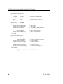
ICP Packet Formats
5.1
5.2
6
.
.
.
.
.
.
.
.
.
.
.
.
.
.
.
.
.
.
.
.
.
.
.
.
75
76
76
76
76
77
78
79
79
79
80
80
83
DLI Packet Format . . . . . . . . . . . . . . . . . . . . . . . . . . . . . . 83
DLI Optional Arguments . . . . . . . . . . . . . . . . . . . . . . . . . . . 85
ICPLOAD Utility
6.1
6.2
6.3
6.4
ICPLOAD Components . . . . . . . . . . . . . .
OS/Impact and Downloaded Files . . . . . . . .
Get or Set the Timeout Value . . . . . . . . . . .
Using ICPLOAD.EXE . . . . . . . . . . . . . . .
6.4.1 Invoking ICPLOAD via the RUN Command
6.4.2 Invoking ICPLOAD as a Foreign Command
6.4.3 ICPLOAD Commands . . . . . . . . . . . .
6.4.3.1 HELP . . . . . . . . . . . . . . . . . .
6.4.3.2 RESET . . . . . . . . . . . . . . . . .
6.4.3.3 LOAD . . . . . . . . . . . . . . . . . .
6.4.3.4 START . . . . . . . . . . . . . . . . .
6.4.3.5 GET . . . . . . . . . . . . . . . . . . .
6.4.3.6 SET . . . . . . . . . . . . . . . . . . .
6.5 ICPLOAD Callable Routines . . . . . . . . . . .
6.5.1 Conventions . . . . . . . . . . . . . . . . .
6.5.1.1 icpreset . . . . . . . . . . . . . . . . .
6.5.1.2 icpload . . . . . . . . . . . . . . . . .
6.5.1.3 icpstart . . . . . . . . . . . . . . . . .
DC 900-1516D
89
.
.
.
.
.
.
.
.
.
.
.
.
.
.
.
.
.
.
.
.
.
.
.
.
.
.
.
.
.
.
.
.
.
.
.
.
.
.
.
.
.
.
.
.
.
.
.
.
.
.
.
.
.
.
.
.
.
.
.
.
.
.
.
.
.
.
.
.
.
.
.
.
.
.
.
.
.
.
.
.
.
.
.
.
.
.
.
.
.
.
.
.
.
.
.
.
.
.
.
.
.
.
.
.
.
.
.
.
.
.
.
.
.
.
.
.
.
.
.
.
.
.
.
.
.
.
.
.
.
.
.
.
.
.
.
.
.
.
.
.
.
.
.
.
.
.
.
.
.
.
.
.
.
.
.
.
.
.
.
.
.
.
.
.
.
.
.
.
.
.
.
.
.
.
.
.
.
.
.
.
.
.
.
.
.
.
.
.
.
.
.
.
.
.
.
.
.
.
.
.
.
.
.
.
.
.
.
.
.
.
.
.
.
.
.
.
.
.
.
.
.
.
.
.
.
.
.
.
.
.
.
.
.
.
. 89
. 90
. 90
. 91
. 91
. 91
. 92
. 94
. 95
. 96
. 97
. 98
. 99
. 100
. 100
. 101
. 102
. 103
5
ICP2432 User’s Guide for OpenVMS Alpha (DLITE Interface)
Index
6
105
DC 900-1516D
List of Figures
Figure 1–1:
Typical Data Communications System Configuration . . . . . . . . . . . 18
Figure 3–1:
DLI/TSI Interface in the Freeway Server Environment . . . . . . . . . . . 36
Figure 3–2:
DLITE Interface in an Embedded ICP2432 Environment. . . . . . . . . . 37
Figure 3–3:
DLI_ICP_DRV_INFO “C” Structure. . . . . . . . . . . . . . . . . . . . . 45
Figure 4–1:
P4 Parameter Format . . . . . . . . . . . . . . . . . . . . . . . . . . . . . 60
Figure 4–2:
“C” Definition of the Device Information Structure . . . . . . . . . . . . 70
Figure 5–1:
“C” Definition of ICP Packet Structure . . . . . . . . . . . . . . . . . . . 84
Figure 5–2:
“C” Definition of DLI Optional Arguments Structure . . . . . . . . . . . 86
DC 900-1516D
7
ICP2432 User’s Guide for OpenVMS Alpha (DLITE Interface)
8
DC 900-1516D
List of Tables
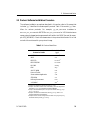
Table 2–1:
Protocol Identifiers. . . . . . . . . . . . . . . . . . . . . . . . . . . . . . . 21
Table 3–1:
DLITE Error Codes . . . . . . . . . . . . . . . . . . . . . . . . . . . . . . 50
Table 3–2:
VMS Errors Mapped to dlerrno . . . . . . . . . . . . . . . . . . . . . . . . 51
Table 3–3:
DLI Error Codes . . . . . . . . . . . . . . . . . . . . . . . . . . . . . . . . 53
Table 5–1:
Comparison of DLI_OPT_ARGS and ICP_PACKET Structures . . . . . . 87
Table 6–1:
ICPLOAD Command Summary . . . . . . . . . . . . . . . . . . . . . . . 92
DC 900-1516D
9
ICP2432 User’s Guide for OpenVMS Alpha (DLITE Interface)
10
DC 900-1516D
Preface
Purpose of Document
This document describes how to use the ICP2432 intelligent communications processor
(ICP) in a peripheral component interconnect (PCI) bus computer running the VMS
operating system.
Intended Audience
This document is intended primarily for VMS system managers and applications programmers.
Organization of Document
Chapter 1 is an overview of the product.
Chapter 2 describes how to install the ICP2432 and protocol software in a VMS system.
Chapter 3 describes the VMS embedded DLITE interface. This chapter supplements the
Freeway Data Link Interface Reference Guide and is of interest primarily to programmers
who are either porting an existing application (currently operational in the Freeway
server environment) to the embedded environment (for example, the PCIbus ICP2432)
or who are developing an initial DLITE application in the embedded environment.
Chapter 4 describes the application interface to the ICP2432 device driver.
Chapter 5 describes the format of packets written to or read from the ICP.
Chapter 6 describes the ICPLOAD utility.
DC 900-1516D
11
ICP2432 User’s Guide for OpenVMS Alpha (DLITE Interface)
3/3/99 Leslie:
Temporarily
remove 1332,
1532, 1541,
and 1543
(post-layoffs)
Protogate References
The following documents provide useful supporting information, depending on the
customer’s particular hardware and software environments. Most documents are
available on-line at Protogate’s web site, www.protogate.com.
General Product Overviews
•
•
•
•
Freeway 1100 Technical Overview
25-000-0419
Freeway 2000/4000/8800 Technical Overview
25-000-0374
ICP2432 Technical Overview
25-000-0420
ICP6000X Technical Overview
25-000-0522
Hardware Support
•
•
•
•
•
•
•
•
•
•
•
Freeway 1100/1150 Hardware Installation Guide
DC 900-1370
Freeway 1200 Hardware Installation Guide
DC 900-1537
Freeway 1300 Hardware Installation Guide
DC 900-1539
Freeway 2000/4000 Hardware Installation Guide
DC 900-1331
Freeway 3100 Hardware Installation Guide
DC 900-2002
Freeway 3200 Hardware Installation Guide
DC 900-2003
Freeway 3400 Hardware Installation Guide
DC 900-2004
Freeway 3600 Hardware Installation Guide
DC 900-2005
Freeway 8800 Hardware Installation Guide
DC 900-1553
Freeway ICP6000R/ICP6000X Hardware Description
DC 900-1020
ICP6000(X)/ICP9000(X) Hardware Description and Theory of
Operation
DC 900-0408
•
•
•
ICP2424 Hardware Description and Theory of Operation
DC 900-1328
ICP2432 Hardware Description and Theory of Operation
DC 900-1501
ICP2432 Hardware Installation Guide
DC 900-1502
Freeway Software Installation Support
•
•
•
•
•
12
Freeway Software Release Addendum: Client Platforms
DC 900-1555
Freeway User’s Guide
DC 900-1333
Getting Started with Freeway 1100/1150
DC 900-1369
Getting Started with Freeway 1200
DC 900-1536
Getting Started with Freeway 1300
DC 900-1538
DC 900-1516D
Preface
•
•
•
Getting Started with Freeway 2000/4000
DC 900-1330
Getting Started with Freeway 8800
DC 900-1552
Loopback Test Procedures
DC 900-1533
Embedded ICP Installation and Programming Support
•
•
•
•
•
ICP2432 User’s Guide for Digital UNIX
DC 900-1513
ICP2432 User’s Guide for OpenVMS Alpha
DC 900-1511
ICP2432 User’s Guide for OpenVMS Alpha (DLITE Interface)
DC 900-1516
ICP2432 User’s Guide for Windows NT
DC 900-1510
ICP2432 User’s Guide for Windows NT (DLITE Interface)
DC 900-1514
Application Program Interface (API) Programming Support
•
•
•
Freeway Data Link Interface Reference Guide
DC 900-1385
Freeway Transport Subsystem Interface Reference Guide
DC 900-1386
QIO/SQIO API Reference Guide
DC 900-1355
Socket Interface Programming Support
•
Freeway Client-Server Interface Control Document
DC 900-1303
Toolkit Programming Support
•
Freeway Server-Resident Application and Server Toolkit Program- DC 900-1325
mer’s Guide
•
•
OS/Impact Programmer’s Guide
DC 900-1030
Protocol Software Toolkit Programmer’s Guide
DC 900-1338
Protocol Support
•
•
•
•
•
•
•
•
•
ADCCP NRM Programmer’s Guide
DC 900-1317
Asynchronous Wire Service (AWS) Programmer’s Guide
DC 900-1324
Addendum: Embedded ICP2432 AWS Programmer’s Guide
DC 900-1557
AUTODIN Programmer’s Guide
DC 908-1558
BSC Programmer’s Guide
DC 900-1340
BSCDEMO User’s Guide
DC 900-1349
BSCTRAN Programmer’s Guide
DC 900-1406
DDCMP Programmer’s Guide
DC 900-1343
FMP Programmer’s Guide
DC 900-1339
DC 900-1516D
13
ICP2432 User’s Guide for OpenVMS Alpha (DLITE Interface)
•
•
•
•
•
•
Military/Government Protocols Programmer’s Guide
DC 900-1602
SIO STD-1200A (Rev. 1) Programmer’s Guide
DC 908-1359
SIO STD-1300 Programmer’s Guide
DC 908-1559
X.25 Call Service API Guide
DC 900-1392
X.25/HDLC Configuration Guide
DC 900-1345
X.25 Low-Level Interface
DC 900-1307
Document Conventions
The term “ICP,” as used in this document, refers to the physical ICP2432, whereas the
term “device” refers to all of the VMS software constructs (device driver, I/O database,
and so on) that define the device to the system, in addition to the ICP2432 itself.
Program code samples are written in the “C” programming language.
Ginni note:
Add
description.
Document Revision History
The revision history of the ICP2432 User’s Guide for OpenVMS Alpha (DLITE Interface),
Protogate document DC 900-1516D, is recorded below:
Revision
Release Date
Description
DC 900-1516A
December 1998
Original release with the DLITE interface
DC 900-1516B
December 1998
Minor changes throughout
DC 900-1516C
March 1999
Add ICPLOADVMS.COM file (Section 2.5 on page 29)
Add new DLITE errors (Table 3–1 on page 50)
DC 900-1516D
February 2002
Change contact info to Protogate. Change file prefix
from SIMPACT_ to ICP2432_. Add additional
information on software and driver installation.
Customer Support
If you are having trouble with any Protogate product, call us at (858) 451-0865 Monday
through Friday between 8 a.m. and 5 p.m. Pacific time.
14
DC 900-1516D
Preface
You can also fax your questions to us at (877) 473-0190 any time. Please include a cover
sheet addressed to “Customer Service.”
We are always interested in suggestions for improving our products. You can use the
report form in the back of this manual to send us your recommendations.
DC 900-1516D
15
ICP2432 User’s Guide for OpenVMS Alpha (DLITE Interface)
16
DC 900-1516D
Chapter
1
Product Overview
The Protogate ICP2432 data communications product allows PCIbus computers running the VMS operating system to transfer data to other computers or terminals over
standard communications circuits. The remote site need not have identical equipment.
The protocols used comply with various corporate, national, and international standards.
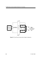
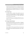
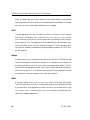
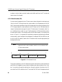
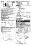
The ICP2432 product consists of the software and hardware required for user applications to communicate with remote sites. Figure 1–1 is a block diagram of a typical system configuration. Application software in the VMS system communicates with the
ICP2432 by means of the Protogate-supplied device driver.
The ICP controls the communications links for the user applications. The user application writes commands and data to the ICP in the form of packets. The user application
also reads responses and data from the ICP in the form of packets. All packets conform
to the format described in Chapter 5.
DC 900-1516D
17
ICP2432 User’s Guide for OpenVMS Alpha (DLITE Interface)
User
Application
Processes
Host Driver
(ZJDRIVER.EXE)
P
C
I
b
u
s
Communication
link
ICP
•
•
•
•
•
•
Data links
to remote computer
or data network
Communication
link
3421
Figure 1–1: Typical Data Communications System Configuration
18
DC 900-1516D
Chapter
2
Software Installation
A typical software installation may contain two or more distribution media packages
(tapes, CDs, and so on). One package contains the ICP2432 VMS device driver, DLITE,
and related files. The other package may contain a specific Protogate protocol and its
related files. This chapter describes the installation procedure for both the device driver
and the protocol software for VMS systems.
The software installation procedures in this chapter refer to directory names that are
used by Protogate’s “Freeway” line of server products.
Before you install the software you must determine the type of installation media you
have. There are two types of installation media: a VMS formatted tape that uses the
VMSINSTAL utility, or a VMS BACKUP saveset taken from a CD or from the Protogate
FTP site. If you have a VMSINSTAL tape, follow the steps in Section 2.3. If you have a
BACKUP saveset, follow the steps in Section 2.4.
DC 900-1516D
19
ICP2432 User’s Guide for OpenVMS Alpha (DLITE Interface)
2.1 Device Driver Installation Procedure
The ICP2432 driver (ZJDRIVER) uses the “Freeway” directory tree for building executable images even if you are not using a Freeway server. The software installation procedures described in this section load the ZJDRIVER and the DLITE API into a new or
already existing Freeway directory.
The following files are placed in the FREEWAY directory:
•
The [FREEWAY.CLIENT.VMS_EMB.BIN] directory contains the executable
images of the ZJDRIVER and driver utilities.
•
The [FREEWAY.CLIENT.VMS_EMB.ICPLOAD] directory contains the source
code for the ICPLOAD protocol download utility.
•
The [FREEWAY.CLIENT.VMS_EMB.DRIVER] directory contains the source code
for the ZJDRIVER and for the IOGEN Configuration Building Module (ICBM)
Utility.
•
The [FREEWAY.CLIENT.VMS_EMB.LIB] directory contains the DLITE library
that is used when linking a VMS program that will communicate with the protocol software on the ICP.
Use the following procedure to install the ZJDRIVER, ICPLOAD, and DLITE software
files on your system.
Step 1: Determine the type of installation media you have. There are two types of
installation media: a VMS formatted tape that uses the VMSINSTAL utility, or a VMS
BACKUP saveset taken from a CD or from the Protogate FTP site.
Step 2: To install the driver software from a VMS formatted media using the
VMSINSTAL utility, refer to Section 2.3 on page 23. To install the driver software from
a VMS BACKUP saveset, refer Section 2.4 on page 27.
20
DC 900-1516D
2: Software Installation
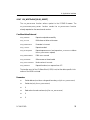
2.2 Protocol Software Installation Procedure
The software installation procedures described in this section refer to file names that
include a “ppp” identifier to indicate a specific protocol. Table 2–1 shows the “ppp” identifiers for various protocols. For example, ppp_FW_2432.MEM translates to
BSC3270_FW_2432.MEM for BSC3270 or X25_FW_2432.MEM for X.25. Note that some
newer protocol releases have image names that fit within the DOS 8.3 format (for example: X25_2432.MEM). Check the release notes in the protocol distribution kit to find
out which format is used for your protocol image.
Table 2–1: Protocol Identifiers
Protocol or Toolkit
Protocol Identifier
(ppp )
AUTODIN
autodin1
AWS
aws
BSC3270
bsc32702
BSC2780/3780
bsc3780b
DDCMP
ddcmp
FMP
fmp
ADCCP NRM
nrm
Protocol Toolkit
sps
Server-resident Application
sra3
STD1200A
s12
Military/Government
mil4
X.25/HDLC
x255
1 Except
for the readme and release notes, where ppp is adn.
Except for the readme, release notes, release history, and load configuration
files where ppp is bsc for both BSC3270 and BSC2780/3780.
3 Except for the executable object for the protocol software where ppp is sps
(sps_fw_2432.mem).
4 Except for the readme and release notes, where ppp is mgn, where n is a
Protogate-supplied product designator.
5
Except for the DLI and TSI configuration files which are apidcfg and apitcfg
and the test directory where ppp is x25mgr.
2
DC 900-1516D
21
ICP2432 User’s Guide for OpenVMS Alpha (DLITE Interface)
The following files are in the FREEWAY directory:
•
README.ppp provides general information about the protocol software
•
RELNOTES.ppp provides specific information about the current release of the
protocol software
•
RELHIST.ppp provides information about previous releases of the protocol soft-
ware
For older Simpact software releases prior to June 1, 1998, the executable object for the
protocol software, ppp_FW_2432.MEM , was distributed in the [FREEWAY.ICPCODE.ICPXXXX.PROTOCOLS] directory. For releases after June 1, 1998, this file is in
the [FREEWAY.BOOT] directory.
For software releases prior to June 1, 1998, the executable object for the system-services
module,
XIO_2432.MEM,
was
distributed
in
the
[FREEWAY.ICP-
CODE.ICPXXXX.OSIMPACT] directory. For releases after June 1, 1998, this file is in the
[FREEWAY.BOOT] directory. The load files provided with protocols with a release date
prior to June 1, 1998 contain a fully qualified path for the protocol and XIO image files.
Such files should be modified to remove the path to the XIO image. This allows your
system to boot the local copy of the XIO image provided in the [FREEWAY.BOOT]
directory.
Step 1: Determine the type of installation media you have. There are two types of
installation media: a VMS formatted tape that uses the VMSINSTAL utility, or a VMS
BACKUP saveset taken from a CD or from the Protogate FTP site.
Step 2: To install the protocol software from a VMS formatted media using the
VMSINSTAL utility, refer to Section 2.3 on page 23. To install the protocol software
from a VMS BACKUP saveset, refer Section 2.4 on page 27.
22
DC 900-1516D
2: Software Installation
2.3 Software Installation Procedure (VMSINSTAL tape)
The software distribution media contains several VMS BACKUP savesets. To install the
software from the distribution media onto your VMS computer, use the VMSINSTAL
utility as described in the following procedure.
Caution
Remember that installing new software overwrites the previous
software.
After the distribution media is mounted, the procedure is automated and only requires
that you respond to menu prompts. Console displays are shown in typewriter type and
your responses are shown in bold type. Follow each entry with a carriage return. The
abbreviation DDCU signifies that a device name is required.
You might find it useful to perform the installation at a hardcopy terminal. This provides a printed record that you can use for troubleshooting if needed.
Step 1: On the host computer, log in to an account that has system-manager privileges.
Step 2: Insert the distribution media into the appropriate drive.
Step 3: Run VMSINSTAL as follows to install the files from each distribution media to
your VMS computer (V nnnn is the current software version number).
$ @SYS$UPDATE:VMSINSTAL
OpenVMS AXP Software Product Installation Procedure Vnnnn
It is today’s date at current time.
Enter a question mark (?) at any time for help.
DC 900-1516D
23
ICP2432 User’s Guide for OpenVMS Alpha (DLITE Interface)
The computer checks the following conditions:
•
Are you logged in to the system manager’s account? You should install the software from that account; however, any account with the necessary privileges is
acceptable.
•
Do you have adequate account quotas for installing software? VMSINSTAL checks
for the various quota values.
•
Are any users logged on the system? Problems might occur if someone tries to use
the system while you are installing a new release of the software.
Step 4: If there are potential problems with the account quotas, the computer displays:
The following account quotas may be too low.
The computer lists the account quotas that might be too low. Next, it lists any other
active processes.
If any potentially conflicting conditions are noted, the computer gives you the opportunity to stop the installation by displaying the following message:
* Do you want to continue anyway [NO]?
If you answer yes, the computer asks:
Are you satisfied with the backup of your system disk [YES]?
If you answer no, the installation stops so you can save your data before restarting the
installation.
Step 5: If you proceed with the installation, the computer displays the following message. Remember that DDCU means a device name.
* Where will the distribution volumes be mounted: DDCU:
24
DC 900-1516D
2: Software Installation
For DDCU, substitute a device name such as MUA0, MKA100, DUAl, or something similar.
Step 6: The computer displays:
Enter the products to be processed from the first distribution
volume set.
* Products: *
Enter an asterisk (this causes all products to be installed).
Step 7: The computer displays:
* Enter installation options you wish to use (none):
Refer to Digital’s VMS Installation Guide for a list of the VMSINSTAL options and how
to enter them. Press <return> to select the standard installation options.
Step 8: The computer displays:
This installation procedure will place the files on device
SYS$SYSDEVICE.
* Is this acceptable [Y]? y
Press <return> to answer yes (this is highly recommended). If you answer no, you are
prompted to enter the name of a target disk.
Step 9: The computer displays:
This installation procedure will place the product files in
directory [FREEWAY...]
on device ddcu
DC 900-1516D
25
ICP2432 User’s Guide for OpenVMS Alpha (DLITE Interface)
* Is this acceptable [Y]? y
Remember that DDCU means a device name. Press <return> to answer yes (this is highly
recommended). If you answer no, you are prompted to enter the name of a directory.
Step 10: The computer displays:
There are no more questions. The installation will proceed.
The procedure completes automatically. Depending on the speed of your system, this
will take several minutes, then it displays:
%VMSINSTAL-I-MOVEFILES, Files will now be moved to their target directories...
Installation of Product Vnnnn completed at current time.
Step 11: The computer displays:
Enter the products to be processed from the next distribution volume set.
* Products:
If you will be installing another protocol, enter an asterisk (*) to continue. When there
are no other distribution sets, enter exit. The computer displays:
VMSINSTAL procedure done at current time.
The ICP2432 software is now installed onto your computer’s disk.
26
DC 900-1516D
2: Software Installation
2.4 Software Installation Procedure (VMS BACKUP saveset)
Some software distributions or updates from Protogate may be in the form of a ZIP file
or a VMS BACKUP saveset that does not use the VMSINSTAL utility. This section lists
the procedures to install software from this type of distribution.
Caution
Remember that installing new software overwrites the previous
version of that software.
The software distribution will usually contain three files as listed below:
•
filename.BCK: a binary file containing the VMS BACKUP saveset
•
filename.LOG: a text file containing a listing of the BACKUP saveset
•
filename.TXT: a text file containing additional installation instuctions
•
(Where filename is the name of the software distrbution.)
Always read the TXT file included in the distribution as it may contain software notes
and additional installation instructions.
If you have multiple savesets, install the driver/DLITE or DLI saveset first, then install
the protocol savesets into the same Freeway directory tree. The protocol saveset will create the subdirectories needed for it’s specific protocol files and test programs.
Step 1: If the distribution is a ZIP file, unzip the file on a Windows PC to get the BCK,
LOG, and TXT files. If the distribution came on a CD ROM, copy the files from the VMS
distribution directory onto your Windows PC. If you have an unzip utility or a CD
ROM drive on your VMS system, you may extract the distribution files directly on your
VMS system and skip the next step.
DC 900-1516D
27
ICP2432 User’s Guide for OpenVMS Alpha (DLITE Interface)
Step 2: Use FTP in binary (image) mode to copy the saveset (BCK file) from your Windows PC to your VMS system.
Step 3: Convert the saveset file to a record format that will be recognized by the VMS
BACKUP utility. To do this, use the DCL command below:
$ SET FILE /ATTR=(RFM:FIX,RAT:NONE,LRL:32256) filename.BCK
Step 4: Use the VMS BACKUP utility to restore the files on your system. You may
install the software in an already existing Freeway directory tree or create a new one with
this installation. To install the files in a top-level Freeway directory, use the following
DCL command:
$ BACKUP/NEW filename.BCK/SAVESET [000000...]
To create a Freeway directory tree as a subdirectory, use the following DCL command as
an example:
$ BACKUP/NEW filename.BCK/SAVESET [PROTOGATE.VMS072...]
The software is now installed onto your computer’s disk.
28
DC 900-1516D
2: Software Installation
2.5 Loading the ICP2432 Driver
The following procedure describes how to load the VMS device driver (ZJDRIVER) for
the ICP2432. Once the device driver is loaded on your system, it does not have to be
reloaded until the system is rebooted. The procedure also provides instruction on how
to configure your system so that the ZJDRIVER is loaded automatically during system
startup.
Step 1: Verify that you have installed one or more ICP2432 boards in your computer,
as described in the ICP2432 Hardware Installation Guide.
Step 2: Verify that you have installed the ZJDRIVER and DLITE software on your disk
drive.
Step 3: Set your default directory to the embedded “binary” subdirectory within the
Freeway directory tree as follows. DDCU: is the name of the disk device that contains
the Freeway tree:
$ SET DEF DDCU:[FREEWAY.CLIENT.VMS_EMB.BIN]
Step 4: Execute the configuration command file for the driver. This DCL command file
will link the ZJDRIVER and copy it to the proper system directory. This command file
also links the driver support programs and creates driver-related command files that are
customized for your system.
$ @ZJCONFIGURE
Step 5: Set the ICP2432_ prefix for the driver by using the SYSMAN utility. First display
the current prefix list:
$ MCR SYSMAN
SYSMAN> IO SHOW PREFIX
DC 900-1516D
29
ICP2432 User’s Guide for OpenVMS Alpha (DLITE Interface)
SYSMAN-I-OUTPUT, command execution on node GABIN
SYSMAN-I-IOPREFIX, the current prefix list is: SYS$,DECW$
The current prefix list is SYS$,DECW$. The empty string equates to the prefix SYS$.
Next set the ICP2432_ prefix:
SYSMAN> IO SET PREFIX="SYS$,DECW$,ICP2432_"
Step 6: Use autoconfigure to configure the ICP2432 cards in the system:
SYSMAN> IO AUTOCONFIGURE /SELECT=ZJ*
Step 7: Exit the SYSMAN utility:
SYSMAN> EXIT
Step 8: Check the ICP device status. Each ICP board will appear on the system as
devices ZJA0, ZJB0, etc. in the order that they were placed on the PCI bus. Use the following command to check that all installed ICP boards were configured and have
“online” status:
$ SHOW DEVICE ZJ
Step 9: If you prefer to use autoconfigure to automatically load ZJDRIVER as part of
the system startup (recommended), add the following line as the last line of the
SYS$MANAGER:SYCONFIG.COM file.
@[FREEWAY.CLIENT.VMS_EMB.BIN]ICP2432_ICBM_INSTALL.COM
30
DC 900-1516D
2: Software Installation
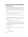
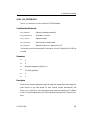
2.6 Loading the Protocol Software
The following procedure describes how to load the protocol software into the ICP2432
boards. Note that you may load and reload the protocol software as many times as you
wish without having to reload the VMS device driver (ZJDRIVER) for the ICP2432. The
procedure also provides instruction on how to configure your system so that the protocol software is loaded automatically at system startup.
Step 1: To download the protocol software to a single ICP, use the command file ICPLOADVMS.COM located in the [FREEWAY.CLIENT.VMS_EMB.BIN] directory. This
command file uses the ICPLOAD utility described in Chapter 6.
ICPLOADVMS.COM uses the script file that is placed in the [FREEWAY.BOOT] direc-
tory during protocol software installation (performed in Section 2.2). Check this directory for the script file of the protocol you wish to download.
The syntax for executing ICPLOADVMS.COM is as follows:
$ @ICPLOADVMS device_name script_file_name dlite_flag
Where the command line parameters are defined as follows:
device_name
Device name of the ICP to be downloaded
(for example, ZJA0 , ZJB0, …)
script_file_name
Script file name placed in the [FREEWAY.BOOT]
directory during protocol software installation
(for example, fmpload, spsload, …)
dlite_flag
DLITE mode select flag. If you are using the DLITE
embedded interface described in Chapter 3, set the
dlite_flag to “dlite” or “DLITE”. If you are interfacing
directly to the ZJDRIVER without DLITE (non-API
mode), then leave this field blank. For more details
on the DLITE mode, see Section 4.4 on page 79.
DC 900-1516D
31
ICP2432 User’s Guide for OpenVMS Alpha (DLITE Interface)
Note
ICPLOADVMS searches for the script file and the installed protocol
software image (for example, fmpload and FMP_FW_2432.MEM) in
the specified directory. If not found in the specified directory, then
it searches in the [FREEWAY.BOOT] directory. If the directory is
not specified, the current directory is used. If the script file can not
be found, ICPLOADVMS returns an error.
Step 2: Execute ICPLOADVMS.COM to download the protocol software onto a single
ICP2432 as shown in the example below:
$ @ICPLOADVMS ZJA0 fmpload DLITE
Processing DKA200:[FREEWAY.BOOT]FMPLOAD.
Resetting ZJA0. This will take about 15 seconds...
Loading Firmware DKA200:[FREEWAY.BOOT]XIO_2432.MEM...
Loading Firmware DKA200:[FREEWAY.BOOT]FMP_FW_2432.MEM...
Starting Firmware (DLITE) ...
Step 3: Use the ICP2432_STARTUP.COM command file located in the [FREEWAY.CLIENT.VMS_EMB.BIN] directory to download multiple ICP boards or to set up to down-
load the protocol software on system startup. This file uses ICPLOADVMS.COM to load
protocol images one or more ICP boards.
Edit the ICP2432_STARTUP.COM file and modify the example lines to reflect your specific script file name and device name. Add lines for downloading multiple ICP boards.
The following example downloads the FMP protocol software to device ZJA0 using the
DLITE embedded interface (described in Chapter 3).
32
DC 900-1516D
2: Software Installation
$! Download Protocol Software
$!
$! $ICPLOADVMS device-name download-script-file dlite-flag
$!
$!
$ ICPLOADVMS ZJA0 fmpload DLITE
$
Step 4: Execute the ICP2432_STARTUP.COM file from its directory to download the
protocol(s) to the ICP board(s) you specified:
$ @ICP2432_STARTUP
Step 5: If you prefer to load the protocol software into the ICP board(s) during system
startup (rather than performing Step 2 or Step 4), you can add a line at the end of your
system startup command file (SYS$MANAGER:SYSTARTUP_VMS.COM) to run the
ICP2432_STARTUP.COM file as follows:
$ @DDCU:[FREEWAY.CLIENT.VMS_EMB.BIN]ICP2432_STARTUP
DC 900-1516D
33
ICP2432 User’s Guide for OpenVMS Alpha (DLITE Interface)
34
DC 900-1516D
Chapter
Techpubs —
Terminology
Cautions: 1)
use blocking
and nonblocking I/O
(instead of
synchronous
and
asynchronou
s 2) use
“Raw
operation”
rather than
“Raw mode”
3
Programming Using the
DLITE Embedded Interface
3.1 Overview
This chapter primarily describes the differences between the data link interface (DLI) to
Freeway (as described in the Freeway Data Link Interface Reference Guide) and the
DLITE embedded interface in a OpenVMS system, referred to as “DLITE.” Changes to
the scope and nature of Freeway DLI support are described.
This chapter should be read by application programmers who are doing one of the following:
•
Porting an existing application (currently operational in the Freeway environment) to the embedded environment (for example, the embedded ICP2432
PCIbus board).
•
Developing an initial DLITE application in the embedded environment. You
should first read the Freeway Data Link Interface Reference Guide and have it available as your primary reference.
In addition to the Freeway Data Link Interface Reference Guide, the following Protogate
reference documents are of interest to application programmers:
•
Freeway Client-Server Interface Control Document (for writing to the socket level)
•
The applicable protocol-specific programmer’s guide for your application.
DLITE is a new, streamlined interface designed specifically for the embedded interface
to the ICP2432 board. The interface provides new capabilities while retaining the
majority of the “Freeway DLI” (henceforth referred to as DLI) capabilities. By using
DC 900-1516D
35
ICP2432 User’s Guide for OpenVMS Alpha (DLITE Interface)
DLITE, developers can concentrate on the communication requirements of the
ICP2432 rather than the details required by the VMS interface and the ICP2432
OpenVMS driver, thereby reducing programming complexity and development time.
DLITE can be thought of as a communications pipe to the ICP2432. It is compatible
with the existing Freeway DLI (with caveats described in Section 3.3.1 on page 38).
DLITE provides a high-level open/close/read/write interface to the ICPs. It supports
only non-blocking I/O.
3.2 Embedded Interface Description
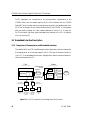
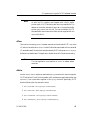
3.2.1 Comparison of Freeway Server and Embedded Interfaces
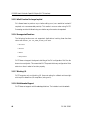
The traditional DLI and TSI interface supports client applications communicating with
the Freeway server on a local-area network (LAN). This type of interface is shown in
Figure 3–1. In an embedded environment, the application does not access a network in
communicating with the ICP.
Freeway
Client
Application DLI TSI
TCP/IP
TCP/IP
Socket Interface
DLI Binary
Configuration File
192.52.107.100
SRA
Msg
TSI Mux
ICP0
ICP1
WAN
Protocols
ICP2
ICP3
3400
Shared Memory
Interface
Ethernet
Industry
Standard Bus
Client
192.52.107.99
TSI Binary
Configuration File
dlicfg
tsicfg
DLI
TSI
DLI Text
Configuration Configuration Configuration
Preprocessor Preprocessor
File
(off-line)
(off-line)
TSI Text
Configuration
File
Figure 3–1: DLI/TSI Interface in the Freeway Server Environment
36
DC 900-1516D
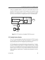
3: Programming Using the DLITE Embedded Interface
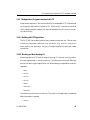
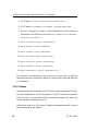
Instead, the embedded application using DLITE communicates directly with the
OpenVMS ICP2432 driver (through the VMS interface), which accesses the locally
attached ICP. This interface is shown in Figure 3–2. In this environment no Freewaytype communications take place; it is designed specifically for the embedded system.
ICP0
VMS
Interface
PCI
Driver
ICP1
WAN
Protocols
ICP2
ICP3
3515
Client
Application DLITE
PCIbus
VMS
DLITE Binary
Configuration File
dlicfg
DLI
DLITE Text
Configuration Configuration
Preprocessor
File
(off-line)
Figure 3–2: DLITE Interface in an Embedded ICP2432 Environment
3.2.2 Embedded Interface Objectives
The DLITE interface was designed as a streamlined interface to the ICP2432. It supports
only Raw operation protocols, which means that the application is responsible for all
communications with the ICP. DLITE supports only non-blocking I/O.
DLITE was designed to maximize portability between existing applications. The objective was an interface that would require “no changes” when porting from a Freeway
environment to an embedded environment. While this objective has been met (for Raw
operation using non-blocking I/O), there are differences between these environments,
as well as differences in system behavior. These differences are addressed in the following sections.
DC 900-1516D
37
ICP2432 User’s Guide for OpenVMS Alpha (DLITE Interface)
3.3 DLITE Interface
The DLITE interface is described here in terms of enhanced capabilities, limitations and
caveats, the API itself, configuration files, and logging/tracing (see Section 3.3.4).
Within each context, necessary changes and any behavior differences are noted.
3.3.1 DLITE Limitations and Caveats
3.3.1.1 Raw Operation Only
DLITE supports only Raw operation. As with DLI, Raw operation means that the API
sends nothing to the ICPs except that which is provided by the application for transmission; therefore, the client application must handle all the following:
•
Configuration of the ICP/Protocol
•
ICP and protocol control data (using the DLI OptArgs structure accompanying
each dlRead and dlWrite request)
•
I/O details of the specific protocol
Raw operation especially impacts configuration of the ICP. Whereas Normal operation
performs ICP configuration for the application using information from the DLI configuration file, the application using Raw operation is totally responsible for configuration. The DLI configuration file does not support “protocol” parameters (in fact, their
presence results in errors during configuration file processing because they are not
allowed in Raw operation).
3.3.1.2 No LocalAck Processing Support
Local acknowledgment (LocalAck) processing is not supported. When data is written to
an ICP, the user receives an acknowledgment that the ICP did in fact receive that data
(refer to your protocol-specific programmer’s guide for details). The Freeway DLI does
support a “LocalAck” capability that hides this from the application programmer (pre-
38
DC 900-1516D
3: Programming Using the DLITE Embedded Interface
vious writes are not posted as complete until DLI receives this LocalAck, then the
LocalAck is thrown away). However, the DLITE user is responsible for receiving each
LocalAck and performing any necessary processing. The DLITE behavior is exactly the
same as when the DLI LocalAck configuration parameter is set to “no”. This generally
implies the client application should post a dlRead after each dlWrite to receive the
expected Local Ack.
3.3.1.3 AlwaysQIO Support
DLI optionally supported an “AlwaysQIO” feature (applicable only when using
non-blocking I/O), which restricted notification of completed I/O to callback invocations only. If an I/O completed immediately in the I/O request, the completion would
not be reported with the return of the dlRead or dlWrite request. Instead, notification
would be through the user-supplied callback.
DLITE always behaves as if the AlwaysQIO configuration parameter is set to “yes” (nonblocking I/O only). Non-blocking I/O should always return with EWOULDBLOCK
while the I/O completes.
3.3.1.4 Changes in Global Variable Support
DLI maintained three global variables; dlerrno, iICPStatus, and cfgerrno. The global variables iICPStatus and cfgerrno are not supported for DLITE. The iICPStatus value simply
returned the value contained in the ICP status field, which is now available to the
DLITE application in the iICPStatus field from the OptArgs. The information in cfgerrno
is no longer available.
The dlerrno variable is still available, but has been redefined for DLITE as a function call
returning an integer (int _dlerrno()). Reference to dlerrno becomes a function call which
returns the last error. Note that this definition precludes using dlerrno as an “L-value” in
a “C” expression.
DC 900-1516D
39
ICP2432 User’s Guide for OpenVMS Alpha (DLITE Interface)
3.3.1.5 dlInit Function No Longer Implied
DLI allowed users to perform dlOpen before calling dlInit (dlInit would be invoked if
required, not a recommended practice). This results in an error when using DLITE.
Processing must be initialized using dlInit before any other service is requested.
3.3.1.6 Unsupported Functions
The following functions are not supported. Applications invoking these functions
return with the DLI_XX…XX_ERR_NEVER_INIT error.
•
dlControl
•
dlListen
•
dlPost
•
dlSyncSelect
DLITE does not support the dynamic building of the DLI configuration file if the .bin
does not currently exist. This means that DLITE expects the binary configuration file to
exist at run time in order to function properly.
3.3.1.7 Blocking I/O
DLITE supports only non-blocking I/O. Users not opting for callback routines might
wish to poll to determine I/O completion (using dlPoll).
3.3.1.8 Multithreaded Support
DLITE does not support multithreaded applications. The interface is not threadsafe.
40
DC 900-1516D
3: Programming Using the DLITE Embedded Interface
3.3.2 The Application Program’s Interface to DLITE
Except where described in the previous sections, the embedded DLITE interface does
not change the application’s interface to DLI. While the DLI interface has remained
intact, changes have been made in both the methods supporting DLI and in the underlying functionality.
3.3.2.1 Building a DLITE Application
The DLITE API is provided on a static library named LIBVMSEMB.OLB. The user must
include the preprocessor definitions VMS and DLITE (e.g., /DEFINE=(VMS,DLITE)
when building the application using the Protogate-supplied libraries and header
include files.
3.3.2.2 Blocking and Non-blocking I/O
As described above, DLITE does not support blocking I/O. However, some of the functions are implemented in a blocking manner. The following functions will effectively
block by not returning to the application until all processing is completed for the service
requested:
•
dlInit
•
dlOpen
•
dlClose
•
dlTerm
•
dlPoll
•
dlBufAlloc
•
dlBufFree
The following functions are non-blocking. They return to the application immediately
after the operation is queued.
•
dlRead
DC 900-1516D
41
ICP2432 User’s Guide for OpenVMS Alpha (DLITE Interface)
•
dlWrite
Using non-blocking I/O, a successful operation returns OK, and dlerrno has the value of
EWOULDBLOCK . The application is notified of I/O completion through the I/O com-
pletion handler (IOCH). The completed I/O operation is retrieved using a dlPoll request
for read/write complete. See Section 3.3.2.5 on page 48 for more information on callbacks and I/O completion.
3.3.2.3 Changes in DLI/TSI
The lack of a network connection has eliminated the need for some of the client/server
communications between the current DLI and TSI. While the user buffer is not affected,
some data previously in the DLI header (i.e. the Freeway header) and the TSI header is
no longer built by the API. These changes are transparent to the user but may be noted
when examining DLITE trace files.
3.3.2.4 Changes in DLI Functions
No changes are required in the user interface to DLI. Some DLI functions have changed
in their implementation, which might affect the user’s expected behavior of the function. Changes in the affected functions are described below.
dlBufAlloc
Implementation of buffer allocation has changed. Rather than allocating buffers from a
pre-allocated buffer pool managed by TSI, buffer allocation requests presented to
DLITE (using dlBufAlloc) invoke VMS system memory services to allocate buffers
(using malloc calls). Do not assume any type of buffer initialization. Also, the size
requested in dlBufAlloc can be thought of as the size requested from the system (the
actual size is somewhat larger, which includes some DLITE overhead requirements). If
the application requests one byte for the data buffer size, it should assume only one byte
is returned.
42
DC 900-1516D
3: Programming Using the DLITE Embedded Interface
User requests are verified against the MaxBufs and MaxBufSize DLITE configuration
parameters. Requests exceeding either of these return a buffer allocation error.
Buffers allocated using dlBufAlloc are allocated with room for the ICP and Protocol
header, and a small DLITE work area prefacing the user’s data area. This area is added
to the user’s request; users do not have to account for these requirements in their buffer
request. DLITE also “tags” each buffer, and verifies the buffer was allocated using
dlBufAlloc before it frees the buffer in dlBufFree. Users can not free a buffer they allo-
cated directly from the system using dlBufFree. Buffer alignment requirements for communications with the VMS ICP2432 driver are performed by dlBufAlloc. The buffer
returned is correctly aligned.
Note
The user’s buffer allocation request should be only for the user’s
data; the space required for the ICP and Protocol headers are
“silently” added to the buffer request by dlBufAlloc. If the application is not using the DLITE buffer allocation service, it must
account for the following:
• Sixteen (16) bytes for the protocol header immediately
prefacing the data buffer
• Sixteen (16) bytes for the ICP header immediately prefacing
the protocol header
• Alignment of the buffer address on the correct boundary
dlBufFree
This service has also changed its implementation. In concert with the change in buffer
allocation, a call to dlBufFree returns the requested buffer to the VMS memory services
(using free). Where previously the user could use the buffer pointer returned with the
successful dlBufFree request (the buffer still existed in the TSI buffer pool), now that
DC 900-1516D
43
ICP2432 User’s Guide for OpenVMS Alpha (DLITE Interface)
buffer is indeed freed. Any further reference to the buffer results in unpredictable
results. Requests with a NULL buffer pointer and attempts to free a buffer not allocated
with dlBufAlloc return with a buffer deallocation error message.
dlInit
The user application must call dlInit before any other DLITE service. If dlInit does not
find the DLI configuration file, it returns the DLI_INIT_ERR_CFG_LOAD_FAILED
error. It does not try to find a DLI source configuration file and perform the configuration processing in-line. The logging and tracing capabilities can fail initialization (e.g.
memory allocation or file I/O errors) without inhibiting DLITE from providing all its
other services. However, Protogate strongly discourages the operation of DLITE without the log facility.
dlOpen
A session open (dlOpen) initiates communications with the VMS ICP2432 driver and
returns with the result of the operation: a session ID if successful, an error otherwise. A
successful open returns a dlerrno of EWOULDBLOCK and generates a callback. This callback could be delivered before the API returns from the open request and would contain the correct session ID. This callback can be ignored, since the application can use
the completion of the open request to control the open operation.
dlPoll
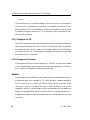
A new poll request of DLI_P0LL_GET_DRV_INFO returns VMS driver information.
The information shown in Figure 3–3 is returned through the pStat parameter provided
by the application (the application provides a pointer to an allocated area of type
DLI_ICP_DRV_INFO ). The area used to return this information must have been allo-
cated by the requesting application.
44
DC 900-1516D
3: Programming Using the DLITE Embedded Interface
typedef struct
{
unsigned long
unsigned long
unsigned long
unsigned long
unsigned long
unsigned char
_DLI_ICP_DRV_INFO
Node;
/* Node assigned */
DeviceNumber;
/* Device Number (ICP) */
NumberOfPorts;
/* Number of ports on ICP */
BufferAlignment; /* Byte alignment requirement */
NumberOfChans;
/* Number of Channels */
Version[DLI_MAX_STRING + 1];
/* Driver version string. */
}
DLI_ICP_DRV_INFO;
typedef DLI_ICP_DRV_INFO *PDLI_ICP_DRV_INFO;
#define DLI_ICP_DRV_INFO_SIZE sizeof(DLI_ICP_DRV_INFO)
Figure 3–3: DLI_ICP_DRV_INFO “C” Structure
Note
The DLI_POLL_TRACE_STORE poll request is not supported by
DLITE.
Cancel
Processing
using
dlPoll
(DLI_POLL_READ_CANCEL
and
DLI_POLL_WRITE_CANCEL) is performed differently. The change should be transpar-
ent to existing applications. New applications can optionally take advantage of this
change.
•
A request to cancel reads or writes (dlPoll request cancel read/write) cancels all
outstanding reads or writes for the session at the time the request is received. In
the Freeway DLI, these were cancelled individually, with the buffer pointer and
OptArgs pointer returned for each request.
•
Cancelled I/O is considered as completed. If a user has five read requests queued
and performs a read cancel, a poll would show five reads completed.
•
Cancelled I/O is returned as previously; each request is returned (with buffer
pointer and OptArgs pointer) with each poll requesting the cancel, until all are
DC 900-1516D
45
ICP2432 User’s Guide for OpenVMS Alpha (DLITE Interface)
returned. Returning the cancelled request reduces the number of I/O completions
by one.
•
Because cancelled I/O is considered completed, cancelled requests are also
returned in response to requests for completed reads and writes (using dlPoll).
These requests are returned with the DLI_IO_ERR_IO_CANCELLED error code.
•
This implementation of cancel processing supports those applications designed
for the Freeway DLI.
•
The user application should ignore the buffer length and associated buffer data
when a cancelled I/O request is returned.
dlRead
There is no change to the dlRead function. However, because DLITE supports Raw
operation only, it does require an associated OptArgs with each I/O request. DLITE fills
in the supplied OptArgs structure with the appropriate data from the ICP and Protocol
headers associated with the read data received from the ICP. Read requests (dlRead) are
returned to the application with the supplied OptArgs structure built from the ICP and
Protocol header received with the data buffer. All the ICP and protocol information is
available in the OptArgs structure when the read buffer is returned.
Non-blocking I/O should expect an EWOULDBLOCK error upon return. A callback is
issued when the read is completed. A callback is invoked for each (both read and write)
read completion.
If the read operation is returned with an error, the data in the OptArgs structure is not
valid. The application must verify the read operation before referencing OptArgs data.
46
DC 900-1516D
3: Programming Using the DLITE Embedded Interface
Note
As with the DLI interface, read requests with a NULL buffer
pointer result in DLITE allocating and returning a read buffer. The
address of the buffer allocated is returned in the supplied buffer
pointer upon return from the call. The user that wants a DLITE
allocated buffer should ensure the buffer pointer supplied with the
dlRead call is NULL.
dlTerm
Termination processing (dlTerm) releases resources and terminates DLITE. Any active
I/O active is cancelled when dlTerm is called. Data buffers associated with the cancelled
I/O are deallocated if those buffers were allocated by DLITE (using dlBufAlloc). OptArgs
buffers are not deallocated. The application should cancel all I/O before terminating.
Note
The user application must perform a dlTerm to release system
resources.
dlWrite
As with dlRead, dlWrite requires an associated OptArgs structure with the write request.
DLITE builds the ICP and Protocol headers, which preface every application buffer (see
dlBufAlloc), from information supplied in this OptArgs structure. Specifically, DLITE
does the following for Raw operation writes:
1. ICP->usClientID = htons (OptArgs->usICPClientID);
2. ICP->usServerID = htons (OptArgs->usICPServerID);
3. ICP->usCommand = htons (OptArgs->usICPCommand);
4. ICP->usParms[0-2] = htons (OptArgs->usICPParms[0-2]);
DC 900-1516D
47
ICP2432 User’s Guide for OpenVMS Alpha (DLITE Interface)
5. DLITE adds ICP->iStatus = LittleEndian ? htons (0x4000) : htons (0);
6. DLITE adds ICP->usDataBytes = htons (BufLen + DLI_PROT_HDR_SIZE);
7. If the ICP command is an Attach, or a Write Expedite, the node ID (previously
retrieved from the VMS driver) is stored in ICP->usParam[0] ( ICP->usParms[0] =
htons( Session->drvNodeID ) ).
8. PROT->usCommand = OptArgs->usProtCommand;
9. PROT->iModifier = OptArgs->iProtModifier;
10. PROT->usLinkID = OptArgs->usProtLinkID;
11. PROT->usCircuitID = OptArgs->usProtCircuitID;
12. PROT->usSessionID = OptArgs->usProtSessionID;
13. PROT->usSequence = OptArgs->usProtSequence;
14. PROT->usXParms[0-1] = OptArgs-> usProtXParms [0-1]);
Non-blocking I/O should expect an EWOULDBLOCK error upon return. A callback is
issued when the write is completed. A callback is invoked for each (both read and write)
write completion.
3.3.2.5 Callbacks
Callbacks represent the completion of an I/O activity; signaling the application to perform actions dependent on that I/O completion. In the DLITE interface, this operation
might be a dlPoll to retrieve session status to ascertain the session’s I/O state, or to
request read/write completes (using dlPoll).
Callbacks are issued in an AST context. Callbacks are delivered sequentially; they are
never reentered by another callback.
48
DC 900-1516D
3: Programming Using the DLITE Embedded Interface
There is no difference between the “main” callback and the “session” callback. They are
initiated sequentially by DLITE. For sake of efficiency, Protogate recommends the user
make use of only one.
To maintain conformity with the existing DLI, callbacks are delivered upon completion
of dlOpen processing. Although dlOpen processing does not generate a callback from the
system (i.e., an AST is not “kicked-off”) the API does, just prior to exiting the dlOpen
processing, emulate the event by placing a “callback” request in an internal callback
queue for delivery to the application.
In a similar manner, callbacks on dlClose requests are generated and delivered by the
API.
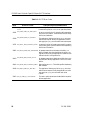
3.3.2.6 DLITE Error Codes
The error codes listed in Table 3–1 have been added to DLITE.
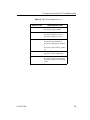
Selected VMS system errors are mapped into existing DLI error codes (dlerrno) so the
application can recognize the error condition and react accordingly. VMS errors are
mapped to dlerrno as described in Table 3–2.
3.3.3 Configuration Files
DLITE uses only the DLI configuration files (TSI configuration files are not used and
are not required). The DLI configuration file must specify “protocol = raw” in the session
sections. With this specification, no parameters are allowed in the protocol section.
The DLI configuration file has been changed to include parameters previously specified
in the TSI configuration file (which is no longer used). These parameters are required
to maintain conformity with those applications porting from DLI to DLITE. This file
has been changed as follows:
MaxBuffers — This parameter has been added to the “main” section. It replaces the
MaxBuffers parameter previously defined in the TSI configuration file. This value
DC 900-1516D
49
ICP2432 User’s Guide for OpenVMS Alpha (DLITE Interface)
Table 3–1: DLITE Error Codes
Value
DLITE Error Code
Description and Recommended Action
–10211 DLI_OPEN_ERR_ICP_INVALID_ST Returned by dlOpen(). The ICP has not been downATUS
loaded with a protocol or is in a non-operational state.
–10231 DLI_OPEN_ERR_NO_DRV_INFO
An error occurred in the I/O interface while requesting
VMS driver information. Terminate the interface, verify
VMS driver installation.
–10518 DLI_READ_ERR_NO_OPTARG
The application failed to provide an OptArgs structure
with the read request. Modify the application to build
and supply an OptArgs structure with each read request.
–10721 DLI_POLL_ERR_INVALID_STATE A request for driver information was made for a session
not currently open. Open the session before requesting
VMS driver information.
–10902 DLI_BUFA_ERR_SIZE_EXCEEDED An attempt was made to allocate more buffers, or a
buffer of greater size, than that defined in the DLI configuration file. Modify the application to adhere to sizes
defined in the DLI configuration file.
–11003 DLI_BUFF_ERR_NONE_ALLOC
An attempt was made to deallocate a buffer when none
were allocated. Modify application to account for used
buffers.
–11004 DLI_BUFF_ERR_ALREADY_FREE Returned by dlBufFree(). The buffer specified has already
been released.
–11918 DLI_WRIT_ERR_NO_OPTARG
The application failed to provide an OptArgs structure
with the write request. Modify the application to build
and supply an OptArgs structure with each write
request.
–12003 DLI_IO_ERR_IO_CANCELLED
The read or write request was cancelled at the request of
the user application.
50
DC 900-1516D
3: Programming Using the DLITE Embedded Interface
Table 3–2: VMS Errors Mapped to dlerrno
VMS Error Code
DC 900-1516D
Applicable dlerrno Codes
SS$IVMODE
DLI_READ_ERR_UNBIND
DLI_WRIT_ERR_UNBIND
SS$INSFMAPREG
DLI_READ_ERR_IO_FATAL
DLI_WRIT_ERR_IO_FATAL
DLI_POLL_ERR_IO_FATAL
SS$TIMEOUT
DLI_READ_ERR_TIMEOUT
DLI_WRIT_ERR_TIMEOUT
DLI_POLL_ERR_READ_TIMEOU
T
DLI_POLL_ERR_WRITE_TIMEO
UT
SS$BUFFEROVF
DLI_READ_ERR_OVERFLOW
DLI_POLL_ERR_OVERFLOW
SS$ACCVIO
DLI_READ_ERR_INVALID_BUF
DLI_WRIT_ERR_INVALID_BUF
DLI_POLL_ERR_INVALID_REQ_
TYPE
51
ICP2432 User’s Guide for OpenVMS Alpha (DLITE Interface)
is returned in the usMaxBufs field of the configuration parameters returned in
response to a dlPoll for system configuration. Operationally, this value limits the
number of buffers the user can have outstanding using the dlBufAlloc function. If
not explicitly defined in the DLI configuration file, the MaxBuffers parameter
defaults to 1024.
MaxBufSize — This parameter has been added to the “main” section. It replaces the
MaxBufSize parameter previously defined in the TSI configuration file. This value
is returned in the iMaxBufSize field of the configuration parameters returned in
response to a dlPoll for system configuration. Operationally, this value represents
the greatest size an application can request using dlRead, and defines the buffer
size used when a dlRead request is made without specifying a buffer (the API allocates and returns this buffer to the application). If not explicitly defined in the
DLI configuration file, the MaxBufSize parameter defaults to 1024.
MaxBufSize — This parameter has been defined in the “session” section of the DLI con-
figuration file. It replaces the MaxBufSize parameter previously defined in the TSI
configuration file (“connection” section). This value is returned in the
usMaxSessBufSize field of the session parameters returned in response to a dlPoll
for session status. Operationally, this value represents the greatest size an application can request to be written using dlWrite. If not explicitly defined in the DLI
configuration file, the MaxBufSize parameter defaults to 1024.
TSICfgName — The TSI configuration file is no longer used.
3.3.4 Logging and Tracing
The DLITE logging and tracing is similar to that supported in the Freeway environment. The Freeway maintains trace and log files internally according to the log and trace
levels defined in the DLI configuration file. Files are circular in nature and are written
to disk when the user application calls the dlTerm function.
There is no longer any need to “decode” the DLI trace file.
52
DC 900-1516D
3: Programming Using the DLITE Embedded Interface
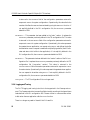
3.3.4.1 Common Logging Service Errors
An application can encounter several errors related to logging and tracing upon initialization with the dlInit function. See Table 3–3. These errors can result from the unavailability of system resources such as memory or disk space. In either case, the errors are
non-fatal and the application proceeds normally; however, logging and tracing are not
activated. The application can ignore these errors (since these services are not
available).
Table 3–3: DLI Error Codes
Error Code
Error Description
Recommended Action
–10006
DLI_INIT_ERR_LOG_INIT_FAILE
D
dlLogInit() failed to start logging. Non-fatal
return from dlInit. Application can ignore this
error (since this service is not available).
–11701
DLI_LOGI_ERR_TRACE_OPEN_F
AILED
dlTrcInit() failed to start tracing. Non-fatal
return from dlInit. Application can ignore this
error (since this service is not available).
3.3.4.2 General Application Error File
DLITE creates an application error file “_DLITERR.TXT” which contains descriptive
run-time errors. Regardless of log and trace levels defined in the DLITE configuration
file, the error file is created in the directory where the application is started. It is a circular file containing a maximum of 1000 entries.
DC 900-1516D
53
ICP2432 User’s Guide for OpenVMS Alpha (DLITE Interface)
54
DC 900-1516D
Chapter
4
Application Interface
Programmers who prefer not to use the DLITE embedded interface (described in
Chapter 3) have the option of writing their VMS application to communicate with the
Protogate protocol software by sending and receiving formatted packets to the ICP2432
device. This is done by issuing VMS queued I/O (QIO) requests to the device driver
(ZJDRIVER) supplied by Protogate. This chapter describes the use of the VMS system
services as they apply to the Protogate device driver.
4.1 Device Driver Interface
The Protogate VMS device driver provides the interface between one or more VMS
application programs and the protocol software on the ICP2432. The VMS program
builds formatted buffers in user space which consist of one or more headers and a data
area. The headers contain information such as command and response codes that both
the program and the protocol software use to determine the type and purpose of each
packet. The Protogate VMS device driver provides a logical path to move these buffers
between AXP and ICP physical memory. The VMS program must do all the interpretation of data within the buffer.
The flow of information between the AXP and ICP generally follows a command/response sequence. For each command sent by the VMS program to the ICP, the
program receives a response from the protocol software. There are, however, exceptions
to the command/response rule due to the asynchronous nature of communications. For
instance, once a link is started, data packets from the remote end of the communication
line can be received at any time. These packets are read by the VMS program through
DC 900-1516D
55
ICP2432 User’s Guide for OpenVMS Alpha (DLITE Interface)
the QIO read path and are not associated with any command sent by the program.
Asynchronous line events such as sudden changes in modem control signals are
reported in the same way. For this reason, the VMS program should always keep a
no-wait read posted to each active link in order to handle any unexpected packets.
Protogate’s standard VMS device driver (ZJDRIVER) provides an interface to the
ICP2432 that is used by several Protogate protocols. Although this driver follows the
general design of most other Digital device drivers, there are some functions that may
be different from other drivers. The following is a list of important facts about the standard Protogate driver:
•
The driver assigns one device name (for example, ZJA0) for each ICP2432 board.
The user program accesses different ICP links through this one device name by
using node numbers (described later in this section). Multiple programs can
access the same device name.
•
Except for download commands, all reads and writes are directed to a node number. Multiple programs can write to the same node number on the same ICP.
However, each program accessing the same ICP should read from a different node
number.
•
Successful completion of a QIO write call simply means that the client buffer
(header and data) has been copied from AXP memory to ICP memory. The VMS
program must post a separate read to receive confirmation of the command or
data.
•
If the VMS program is not able to post a QIO read for an incoming message
immediately, the message is not lost; if the ICP has available memory, it holds the
packet until the read is posted.
•
VMS error codes found in the I/O Status Block (IOSB) of the QIO calls are different from protocol error codes found in the protocol header.
•
56
The Protogate driver does not support timer functions such as timed reads.
DC 900-1516D
4: Application Interface
Your VMS system must have available PCIbus slots in order to use the ICP2432 boards.
After the device driver is installed in the VMS system, ICP boards appear as the device
names ZJAO, ZJBO. ZJCO, and so on.
The device driver supports the following VMS system service calls for normal program
applications:
•
SYS$ASSIGN - Assign a channel
•
SYS$QIO (IO$READxBLK, IO$WRITExBLK) - Read and write data
•
SYS$DASSGN - Close a channel
•
SYS$CANCEL - Cancel pending I/O
•
SYS$QIO(IO$_READxBLK|IO$M_ABORT, IO$_WRITExBLK|IO$M_ABORT)
-
Cancel read and write requests
•
SYS$QIO(IO$_STARTDATA) - Assign a node number for read requests in node
auto-assignment mode
•
SYS$QIO(IO$_SENSEMODE)- Get device driver information
The device driver supports the following VMS system service calls for ICP download
applications:
•
SYS$QIO (IO$INITIALIZE) - Reset an ICP
•
SYS$QIO (IO$LOADMCODE) - Download an ICP
•
SYS$QIO (IO$STARTMPROC) - Start the ICP protocol software
These system services can be accessed from programs written in MACRO-32 assembly
language or any high-level language supported by Digital such as C, FORTRAN,
PASCAL, ADA, BASIC, and COBOL. The following sections describe the system
services normally used by a VMS application programmer who is interfacing to an ICP.
The system service calls are described in more detail in Section 4.2 on page 61.
DC 900-1516D
57
ICP2432 User’s Guide for OpenVMS Alpha (DLITE Interface)
4.1.1 Channel Assignment
The VMS application program must assign a channel to the device driver before any I/O
can take place. To do this, the program uses the SYS$ASSIGN system service. The
format of this system service is shown in Section 4.2.1 on page 61. Once a VMS program assigns a channel to an ICP, it has access to all communication ports on that ICP.
A program can access more than one ICP by assigning a separate channel for each
board. Multiple VMS programs can access the same ICP board by assigning channels to
the same device name. Read and write operations for each of the programs are kept separate through the use of node numbers (described in Section 4.3.2 on page 75).
4.1.2 $QIO Interface
On VMS systems, application programs communicate with the ICP protocol software
through the use of the $QIO system service. The format of the SYS$QIO call as it relates
to the ICP device is shown in Section 4.2.4 on page 63. More detailed information on
the QIO call and parameters can be found in the VMS System Services Reference Manual.
The following sections describe parameters that have specific use with ICP protocol
applications.
4.1.2.1 I/O Function Code
The I/O function code determines whether the QIO operation is a read or a write. Use
IO$WRITEVBLK (write virtual block) when writing a buffer to the ICP and IO$READVBLK (read virtual block) when reading a buffer from the ICP. No other modifiers are
required. The function codes for logical block (IO$WRITELBLK, IO$READLBLK) and
physical block (IO$WRITEPBLK, IO$READPBLK) are also supported, but are normally
not used by ICP programmers.
58
DC 900-1516D
4: Application Interface
4.1.2.2 I/O Status Block (IOSB)
The programmer should always check the status field (first word) of the I/O Status
Block (IOSB) after each QIO completion. This field returns a VMS completion code or
error code that indicates the success of the call or reason for failure. The return codes
used by the ICP device driver are described in Section 4.2.4.6 on page 71. Note that
these error codes indicate VMS errors only and are different than the protocol error
codes that are returned in the data portion of the QIO read. Protocol-specific errors are
described in the Protogate programmer’s guide for the specific protocol you are using.
The fourth word of the IOSB contains the actual number of bytes transferred for READ
operations.
4.1.2.3 Buffer Address and Size (P1 and P2)
The P1 parameter contains the address of the buffer to be transferred to the ICP for
WRITE operations or the address of a buffer to receive data from the ICP for READ
operations. The address can be an array name or pointer to a data area. The buffer consists of the protocol header(s) followed by an optional data area. If a data area exists, it
must immediately follow the protocol header.
For WRITE operations, the P2 parameter equals the total size (in bytes) of the protocol
header(s) plus any data that follows the header. The size of the data area must not
exceed the maximum buffer size specified by the protocol software or a VMS buffer
overflow error occurs. For example, if the maximum ICP buffer size is set to 1024 bytes,
the maximum value of the P2 parameter would be the size of the protocol header(s)
plus 1024.
For READ operations, the P2 parameter equals the size of the program’s read buffer.
This buffer must be large enough to accept the protocol header(s) plus largest data area
expected from the ICP. Using the above example, the read buffer size would always be
header size plus 1024 bytes. When the read completes, the program can obtain the
actual number of bytes transferred from the I/O Status Block (IOSB). Since all ICP data
DC 900-1516D
59
ICP2432 User’s Guide for OpenVMS Alpha (DLITE Interface)
transfers include at least a protocol header, each buffer read from the ICP contains at
least the size of that header.
4.1.2.4 Node Numbers (P4)
Once a channel is assigned to the ICP device name, data is directed to individual ports
(links) on that ICP through the use of a node number in the P4 parameter of the QIO
call. A node number represents a logical full-duplex path to the protocol software on the
ICP. The legal values for node numbers in the ICP driver are 1 to 126. Note that this
range of numbers starts over again for each ICP device name. For example, node 1 on
ZJA0 is different from node 1 on ZJB0. The P4 parameter is a 32-bit word that contains
the read node number in the low byte and the write node number in the next byte, as
shown in Figure 4–1. As a general rule, application programs should place the desired
node number in both low bytes of the parameter (for example, 0101 hex, 0202 hex, and
so on) for all QIO transfers, read or write. The device driver uses the appropriate byte
and ignores the other.
Note
Read and write node numbers should not be confused with
PCIbus node numbers.
31
15
23
unused
unused
0
7
write node number
read node number
Figure 4–1: P4 Parameter Format
The protocol software on the ICP determines how the device driver node numbers are
used. Most of Protogate’s current protocol software uses node numbers to form “session” connections through the device driver. Using this method, all writes to the ICP
use nodes 1 and 2. All reads from the ICP use nodes 3 to 126. Some Protogate protocols
60
DC 900-1516D
4: Application Interface
have the ability to revert to an earlier node number scheme used by Simpact’s ICP3222
and Digital’s Commserver products. This scheme connects a single node number to
each ICP port. Whatever node number scheme or protocol you use, it is transparent to
the VMS device driver. More information about protocol specifics can be found in
Chapter 5.
4.2 Supported VMS System Services
The ICP2432 device driver supports the VMS system services described in the following
sections.
4.2.1 SYS$ASSIGN
Before issuing VMS QIO calls, the application must first assign a channel to an ICP with
the VMS SYS$ASSIGN call. This call sets up an association between this channel and
the ICP on subsequent QIO calls. See the VMS system services manual for a detailed
description of SYS$ASSIGN .
Synopsis
SYS$ASSIGN ( device_name, &channel [,acmode] [,mbxnam] )
Parameters
device_name
ICP device name (for example, ZJA0)
channel
Address of the communication channel that is assigned
Note
The ICP2432 device driver does not support access mode (acmode)
and mailbox (mbxnam).
DC 900-1516D
61
ICP2432 User’s Guide for OpenVMS Alpha (DLITE Interface)
4.2.2 SYS$CANCEL
To cancel all active or pending read or write requests associated with an I/O channel, the
application issues the VMS SYS$CANCEL call. See the VMS system services manual for
a detailed description.
Synopsis
SYS$CANCEL ( channel )
Parameters
channel
Communication channel
4.2.3 SYS$DASSGN
To terminate its association with an ICP device, the application issues the VMS
SYS$DASSGN call for the channel associated with the ICP. See the VMS system services
manual for a detailed description of SYS$DASSGN.
Synopsis
SYS$DASSGN ( channel )
Parameters
channel
62
Communication channel
DC 900-1516D
4: Application Interface
4.2.4 SYS$QIO(W)
To issue VMS read or write I/O calls, the client application issues the VMS SYS$QIOW
or SYS$QIO calls (for I/O with, or without wait). See the VMS system services manual
for a detailed description of SYS$QIOW and SYS$QIO.
Synopsis
SYS$QIO(W) ( [efn], channel, function [,&iosb] [,&astadr] [,astprm],
[,p1] [,p2] [,p3] [,p4] [,p5] [,p6] )
Parameters
efn
Event flag to be set on completion of I/O
channel
Communication channel associated with a device
function
Supported functions are described in Section 4.2.4.1 through
Section 4.2.4.7
iosb
Address of the I/O Status Block (IOSB) fields to receive the I/O
completion status
astadr
Address of an Asynchronous System Trap (AST) routine to be
executed on I/O completion
astprm
Asynchronous System Trap (AST) parameter passed to the AST
routine on I/O completion
P1—P6
Optional device- and function-specific I/O request parameters
The ICP2432 device driver supports these function codes, described in the following
sections:
1. IO$_INITIALIZE[|IO$M_NOWAIT]
2. IO$_LOADMCODE
DC 900-1516D
63
ICP2432 User’s Guide for OpenVMS Alpha (DLITE Interface)
3. IO$_STARTMPROC
4. IO$_READVBLK , IO$_READLBLK, IO$_READPBLK
5. IO$_WRITEVBLK, IO$_WRITELBLK, IO$_WRITEPBLK
All functions are handled as direct I/O using DMA transfer.
64
DC 900-1516D
4: Application Interface
4.2.4.1 IO$_INITIALIZE[|IO$M_NOWAIT]
The IO$_INITIALIZE function initializes the ICP2432.
Condition Values Returned
SS$_NORMAL
Initialization completed successfully
SS$_CANCEL
Request canceled
SS$_CTRLERR
Request not completed; a fatal error occurred
SS$_TIMEOUT
Request timed out; no response from ICP
The transfer count and device-specific information of the I/O Status Block (IOSB) are
not used.
Parameters
None.
Description
If the SS$M_NOWAIT modifier is used, the driver resets the device and returns immediately; it does not wait for initialization to complete.
If the SS$M_NOWAIT modifier is not used, the driver resets the device and initializes
the ICP2432 to prepare for downloading the software.
DC 900-1516D
65
ICP2432 User’s Guide for OpenVMS Alpha (DLITE Interface)
4.2.4.2 IO$_LOADMCODE
The IO$_LOADMCODE function loads a software block onto the ICP2432.
Condition Values Returned
Decreased size
above
Condition,
Parameters,
and
Description to
get
Description
on this page.
SS$_NORMAL
Request completed successfully
SS$_BADPARAM
Parameter is incorrect
SS$_CANCEL
Request canceled
SS$_ILLBLKNUM
ICP load address is incorrect
SS$_INSFMAPREG
DMA error occurred
SS$_TIMEOUT
Request timed out; no response from ICP
The transfer count and device-specific information of the I/O Status Block (IOSB) are
not used.
Parameters
P1
Packet address (must be on a longword boundary)
P2
Packet size (less than 1 megabyte)
P3
0
P4
ICP load address
P5
0
P6
0
Description
The driver accesses user virtual address space (specified by the P1 parameter) to access
the packet. The packet must be set on a longword boundary. For details of the ICP load
address, see the ICP2432 Hardware Description and Theory of Operation.
66
DC 900-1516D
4: Application Interface
4.2.4.3 IO$_STARTMPROC
The IO$_STARTMPROC function starts the ICP2432 software.
Condition Values Returned
SS$_NORMAL
Request completed successfully
SS$_BADPARAM
Parameter is incorrect
SS$_CANCEL
Request canceled
SS$_INVMODE
Software was not downloaded
SS$_TIMEOUT
Request timed out; no response from ICP
The transfer count and device-specific information of the I/O Status Block (IOSB) are
not used.
Parameters
P1
0
P2
0
P3
Node auto-assignment flag (0 or 1)
P4
ICP starting address
P5
0
P6
0
Description
When the P3 node auto-assignment flag is set, the driver changes the mode to assign the
node number of the read request for each channel number automatically. See
Section 4.4 on page 79 for more information about node auto-assignment. For details
of the ICP starting address, see the ICP2432 Hardware Description and Theory of Operation.
DC 900-1516D
67
12/3/98 Leslie:
Roger says this
is correct but
he will work
on better
wording (he
wants a better
term than
“auto
assignment”.
ICP2432 User’s Guide for OpenVMS Alpha (DLITE Interface)
4.2.4.4 IO$_STARTDATA
The IO$_STARTDATA function sets the node number of the read request for this channel number.
Condition Value Returned
SS$_NORMAL
Request completed successfully
SS$_ILLSEQIOOP
Driver was not in node auto-assignment mode
SS$_INVMODE
Software was not downloaded
The device-specific information of the I/O Status Block (IOSB) is set to the node number assigned by the driver.
Parameters
12/3/98 Leslie:
Roger says this
is correct but
he will work
on better
wording (he
wants a better
term than
“auto
assignment”.
P1
0
P2
0
P3
0
P4
0
P5
0
P6
0
Description
The IO$_STARTDATA function must be requested after the node auto-assignment flag
in the IO$_STARTMPROC function is set. If the driver is in node auto-assignment
mode, the IO$_STARTDATA function must be requested before the IO$_READxBLK or
IO$_WRITExBLK function is requested. If the node auto-assignment flag isn’t set, the
driver returns the SS$_ILLSEQIOOP error. See Section 4.4 on page 79 for more information about node auto-assignment.
68
DC 900-1516D
4: Application Interface
4.2.4.5 IO$_SENSEMODE
The IO$_SENSEMODE function returns the driver information.
Condition Value Returned
SS$_NORMAL
Request completed successfully
SS$_ACCVIO
Buffer does not allow write access
SS$_BADPARAM
Parameter is incorrect
The transfer count of the I/O Status Block (IOSB) is set, but the device-specific information of the IOSB is not used.
Parameters
P1
Buffer address
P2
Buffer size
P3
0
P4
0
P5
0
P6
0
Buffer Format
Figure 4–2 shows the device information structure as the driver returns the buffer.
Description
The IO$_STARTDATA function must be requested after the node auto-assignment flag
in the IO$_STARTMPROC function is set. If the driver is in node auto-assignment
mode, the IO$_STARTDATA function must be requested before the IO$_READxBLK or
IO$_WRITExBLK function is requested. If the node auto-assignment flag isn’t set, the
driver returns the SS$_ILLSEQIOOP error. See Section 4.4 on page 79 for more information about node auto-assignment.
DC 900-1516D
69
Note to
myself: This
paragraph is
the same as
the last
paragraph of
Section
4.2.4.4. It that
one changed,
change it here
too.
ICP2432 User’s Guide for OpenVMS Alpha (DLITE Interface)
typedef struct {
int TimeoutValue;
/* Timeout value for the SingleStepDriver */
int Node;
int IcpWasReset;
/* Node number corresponding to file handle. */
/* ICP has been reset since handle opened. */
int DeviceNumber;
int NumberOfPorts;
int IcpState;
int BufferAlignment;
int NumberOfChannel;
/* Device number to which handle is opened. */
/* Number of ports on the ICP. */
/* Current state of the ICP. */
/* Alignment requirement for I/O buffers. */
/* Number of channels open to this ICP. */
int DriverMode;
/* Driver mode of node auto-assignment */
#define MAX_VERSION_LENGTH 80
unsigned char Version[ MAX_VERSION_LENGTH ]; /* Driver version number */
} ZJ_SENSEMODE;
Figure 4–2: “C” Definition of the Device Information Structure
70
DC 900-1516D
4: Application Interface
4.2.4.6 IO$_READxBLK[|IO$M_ABORT]
The IO$_READxBLK function reads a packet from the ICP2432 firmware. The
IO$_READxBLK|IO$M_ABORT function cancels the IO$_READxBLK function already
requested on the same channel number.
Condition Values Returned
SS$_NORMAL
Request completed successfully
SS$_ACCVIO
Buffer does not allow write access
SS$_BADPARAM
Parameter is incorrect
SS$_BUFFEROVF
Received data is larger than specified buffer
SS$_CANCEL
Request canceled
SS$_ILLSEQIOOP
Request sequence error (must request IO$_STARTDATA before
the IO$_READxBLK request)
SS$_INSFMAPREG
DMA error occurred
SS$_INVMODE
Software was not downloaded
SS$_NOSUCHNODE
Node number is incorrect
SS$_TIMEOUT
Request timed out; no response from ICP
The transfer count of the I/O Status Block (IOSB) is set, but the device-specific infor- Decreased size
above
Condition
and
Parameters to
get P6 on this
page.
mation of the IOSB is not used.
Parameters
P1
Packet address (must be on a longword boundary; only for IO$_READxBLOCK)
P2
Packet size (only for IO$_READxBLOCK)
P3
0
P4
Read and write node numbers (only for IO$_READxBLOCK)
P5
0
P6
0
DC 900-1516D
71
ICP2432 User’s Guide for OpenVMS Alpha (DLITE Interface)
Description
The driver accesses user virtual address space (specified by the P1 parameter) to access
the packet. The packet must be set on a longword boundary.
The read and write node numbers are used for communication between the driver and
the ICP2432. The node numbers decide the source and destination of messages. Allowable values are 1 through 126. The read node number of P4 is bit 0 through bit 7. The
write node number of P4 is bit 8 through bit 15. See Section 4.1.2.4 on page 60 for more
information about node numbers.
12/3/98 Leslie:
Roger says this
is correct but
he will work
on better
wording (he
wants a better
term than
“auto
assignment”.
When the node auto-assignment mode is selected, the node number doesn’t have to be
set.
72
DC 900-1516D
4: Application Interface
4.2.4.7 IO$_WRITExBLK[|IO$M_ABORT]
The IO$_WRITExBLK function writes a packet to the ICP2432 firmware. The
IO$_WRITExBLK|IO$M_ABORT function cancels the IO$_WRITExBLK function
already requested on the same channel number.
Condition Values Returned
SS$_NORMAL
Request completed successfully
SS$_ACCVIO
Buffer does not allow write access
SS$_BADPARAM
Parameter is incorrect
SS$_CANCEL
Request canceled
SS$_ILLSEQIOOP
Request sequence error (must request IO$_STARTDATA before
the IO$_WRITExBLK request)
SS$_INSFMAPREG
DMA error occurred
SS$_INVMODE
Software was not downloaded
SS$_NOSUCHNODE
Node number is incorrect
SS$_TIMEOUT
Request timed out; no response from ICP
The transfer count of the I/O Status Block (IOSB) is set, but the device-specific information of the IOSB is not used.
Parameters
P1
Packet address (must be on a longword boundary; only for IO$_WRITExBLK)
P2
Packet size (only for IO$_WRITExBLK)
P3
0
P4
Read and write node numbers (only for IO$_WRITExBLK)
P5
0
P6
0
DC 900-1516D
73
ICP2432 User’s Guide for OpenVMS Alpha (DLITE Interface)
Description
The driver accesses user virtual address space (specified by the P1 parameter) to access
the packet. The packet must be set on a longword boundary.
The read and write node numbers are used for communication between the driver and
the ICP2432. The node numbers decide the source and destination of messages. Allowable values are 1 through 126. The read node number of P4 is bit 0 through bit 7. The
write node number of P4 is bit 8 through bit 15. See Section 4.1.2.4 on page 60 for more
information about node numbers.
74
DC 900-1516D
4: Application Interface
4.3 DLI Session Interface
Protogate protocols designed for use on ICP2432 boards use a session-based method of
communicating between the client application program and the protocol software on
the ICP. This method of communication allows greater flexibility in connecting TCP/IP
sockets to individual ICP ports for the Freeway line of servers. Protogate’s Data Link
Interface (DLI) library uses this session-based interface on both the Freeway server and
embedded ICP boards. If you have previously used Simpact protocols on older ICP
boards, you will find that the session-based interface differs somewhat from the older
interface. As a rule, protocol image files that begin with fw use the DLI session interface.
Inside a Freeway server, a program called msgmux manages protocol sessions for all
applications. When you use Protogate’s standard device driver with a session-based protocol image, your VMS program must take over these session management functions as
described in the following subsections.
4.3.1 DLI Session Basics
A session is made up of a logical connection to an ICP protocol. A session simply defines
a single connection or “service” to an ICP protocol. A session is started by “attaching”
to an ICP port number using a specific access mode. Sessions have different access
modes depending on the protocol. Consult your protocol programmer’s guide for
details.
4.3.2 Use Of Node Numbers (DLI)
When using DLI sessions, all writes to the ICP are performed on nodes 1 and 2. All reads
are performed on nodes 3 to 126. When using multiple programs to access the same
ICP, different read nodes are used to direct packets to the correct program. The following subsections describe the node numbers in more detail.
DC 900-1516D
75
ICP2432 User’s Guide for OpenVMS Alpha (DLITE Interface)
4.3.2.1 Node 1
Node 1 is the primary node number to which all data is written. The VMS driver allows
multiple programs to write to the same node number. The P4 parameter in the QIO call
should be 0x0101 for all writes.
4.3.2.2 Node 2
Node 2 is the alternate write node. Its use varies per protocol. In some documents,
node 2 is referred to as the “express node” for sending priority packets to the ICP. However, for most protocols this node is treated the same as node 1. Unless your protocol
programmer’s guide says otherwise, you should not use node 2 to write data packets to
the ICP. You should use node 2 to send the TERMINATE command described in
Section 4.3.3.3 on page 79.
4.3.2.3 Nodes 3 through 126
Nodes 3 through 126 are used as “read only” nodes and are assigned for use by the
ATTACH command. Although most Protogate protocols allow multiple sessions per
node number, it is easier if your programs assign a separate node number per session.
The Freeway server assigns the next lowest available read node number for each new
connection it receives. Again, your program does not have to follow this scheme. It
would be easier to assign a fixed node number for each ICP port (or service). For example, a session to port 0 would always use node 3, port 1 would use node 4, and so on.
4.3.3 DLI Session Commands
The following commands are used to establish and terminate sessions with Protogate
protocols on the ICP. The command codes described here are placed in the command
field of the ICP header (see Chapter 5).
76
DC 900-1516D
4: Application Interface
4.3.3.1 ATTACH Command
The ATTACH command creates a session between your program and the protocol software on the ICP.
The following values must be placed in the ICP header of the ATTACH command:
Command field = DLI_ICP_CMD_ATTACH
Status field
= hex 4000 (this tells the ICP to swap bytes for VMS systems)
Params[0]
= read node number
Some protocols may require you to fill in fields in the protocol header portion of the
ATTACH command with such things as access mode and protocol type. Consult your
protocol programmer’s guide for details.
Your program can read the ATTACH response by posting a QIO read to the node number you supplied in the ATTACH command. The two most important values to read
from the ATTACH response are the status field of the ICP header and the session ID
field of the protocol header. The status field contains 0 if the ATTACH command was
successful and an error code if it was unsuccessful. If the ATTACH was successful, the
session ID field contains a number associated with this session. This number must be
placed in the session ID field of all subsequent writes to this session.
DC 900-1516D
77
ICP2432 User’s Guide for OpenVMS Alpha (DLITE Interface)
4.3.3.2 DETACH Command
The DETACH command closes an individual session between your program and the
protocol software on the ICP. The following values must be placed in the ICP header of
the ATTACH command:
ICP Header:
Command field
= DLI_ICP_CMD_DETACH
Status field
= hex 4000 (this tells the ICP to swap bytes for VMS systems)
Protocol Header:
Session ID field
= session ID from ATTACH command
The DETACH command disassociates the protocol session ID from the session, freeing
it for use by another program. Your program can read the DETACH response from the
read node number specified in the ATTACH command for the session.
78
DC 900-1516D
4: Application Interface
4.3.3.3 TERMINATE Command
The TERMINATE command closes all sessions that use a particular read node number.
The following values must be placed in the ICP header of the ATTACH command:
Command field
= DLI_ICP_CMD_TERM
Status field
= hex 4000 (this tells the ICP to swap bytes for VMS systems)
Params[0]
= read node number
If there are one or more sessions using a single read node number, the TERMINATE
command forces the protocol software to do implied DETACH commands to each open
session. The ICP sends a TERMINATE response to the supplied read node.
4.3.4 ICP Discarded Packets
When the protocol software on the ICP receives a packet that has an invalid protocol
session ID, it writes the packet back through node 1. For this reason, you may want to
have a separate program which reads packets from node 1 and displays the contents.
4.4 Node Auto-Assignment Mode for Read Requests
The driver supports the node auto-assignment mode for read requests on DLI session
interfaces. The driver automatically assigns the node number of the read request for
each device assigned by the SYS$ASSIGN function. The application doesn’t have to set
the node numbers in the read and write node number (P4) of the IO$_READxBLK
function.
The driver mode must be changed to use node auto-assignment. This is done by setting
the flag of IO$_STARTMPROC function.
The application must also issue the IO$_STARTDATA function to assign the node number for the device assigned by the SYS$ASSGN function.
DC 900-1516D
79
ICP2432 User’s Guide for OpenVMS Alpha (DLITE Interface)
Follow these steps to use the node auto-assignment:
12/3/98 Leslie:
Ginni had the
first part of
the first bullet
underlined,
but no note.
1. Download the protocol software with set the flag of IO$_STARTMPROC function.
(When the icpload utility is used, set the /DLITE qualifier on the START command. See Section 6.4.3.4 on page 97 for more information about the START
command.)
2. The application assigns the device and gets the channel number.
3. The application issues IO$_STARTDATA to assign the node number and get it.
(See Section 4.2.4.4 on page 68 for more information about IO$_STARTDATA.)
4. The application issues IO$_READxBLK and IO$_WRITExBLK .
4.5 Compatibility with Older ICP Protocols
Protogate’s BSC and FMP protocol software for the ICP2432 now has the capability of
emulating the interface used by older ICP products such as the ICP1622, ICP3222, and
DEC Commserver. If you already have a VMS program using BSC or FMP on one of
these devices, your interface does not have to change. When you send the Set Buffer Size
command to node 1 (port 0), the BSC or FMP software automatically detects (from the
size of the packet) that you are using the older style of interface. The protocol software
then posts reads on all nodes associated with port numbers in addition to the data ack,
control, and trace nodes.
When using this method of interface, each read or write must contain the 8-byte protocol header and commands as described in your original BSC or FMP programmer’s
guide.
4.6 Protocol Toolkit
If you have purchased Protogate’s Protocol Toolkit for the ICP2432, the Sample Protocol Software (SPS) example uses the DLI session interface. The toolkit allows you to
change this to whatever style of interface you want to use, however, Protogate recom-
80
DC 900-1516D
4: Application Interface
mends that you use the DLI session interface so that you can also use the protocol image
in a Freeway environment.
DC 900-1516D
81
ICP2432 User’s Guide for OpenVMS Alpha (DLITE Interface)
82
DC 900-1516D
Chapter
5
Roger — Bill
Reid’s review
comment
was “What is
this and why
is it?” Maybe
it’s
redundant
now that we
are putting
all the packet
info in the
protocol
documents
...Leslie
ICP Packet Formats
This chapter describes the packet formats used by Protogate protocols. The packet
formats that are written to the ICP2432 are the same whether the ICP is attached to a
Freeway server or a PCI bus in your VMS system. Because most Protogate protocol programmer’s guides mention commands and responses as they apply to the Freeway
server, this chapter covers both Freeway and device driver use of packets.
5.1 DLI Packet Format
The OpenVMS ICP driver QIO interface provides a block-transfer interface between a
client application and the protocol software resident on the embedded ICP. From the
application’s perspective, these packets consist of message blocks composed of an ICP
header structure followed by a protocol header structure followed by an optional data
array. Figure 5–1 shows the “C” definition of this ICP packet structure.
When preparing a packet to write to the ICP, the application must initialize the
usICPCount field with the size in bytes of the PROT_HDR structure (16) plus the size of
the data array that follows it. After reading a packet from the driver, the application may
compute the size of the data array that follows the PROT_HDR structure by subtracting
16 from the value of the usICPCount field in the ICP_HDR structure.
Note that the ICP_HDR structure must be in network byte-order (Big Endian). This
means that the VMS program must swap bytes in the ICP header before writing packets
to the ICP. The VMS program must also swap bytes in the ICP header after reading each
packet from the ICP. The PROT_HDR structure remains in the client computer’s natural
byte order, which is Little Endian for AXP systems.
DC 900-1516D
83
ICP2432 User’s Guide for OpenVMS Alpha (DLITE Interface)
typedef struct _ICP_PACKET
{
ICP_HDR
icp_hdr;
PROT_HDR
prot_hdr;
char
*data;
} ICP_PACKET;
typedef struct
_ICP_HDR
{
unsigned short usICPClientID;
unsigned short usICPServerID;
unsigned short usICPCount;
unsigned short usICPCommand;
short iICPStatus;
unsigned short usICPParms[3];
} ICP_HDR;
typedef struct _PROT_HDR
{
unsigned short usProtCommand;
short iProtModifier;
unsigned short usProtLinkID;
unsigned short usProtCircuitID;
unsigned short usProtSessionID;
unsigned short usProtSequence;
unsigned short usProtXParms[2];
} PROT_HDR;
/* Network-ordered header */
/* Host-ordered header */
/* Variable length data array */
/* Old su_id */
/* Old sp_id */
/* Size of PROT_HDR plus data */
/* ICP's command */
/* ICP's command status */
/* ICP's extra parameters */
/* Protocol command */
/* Protocol command's modifier */
/* Protocol link ID */
/* Protocol circuit ID */
/* Protocol session ID */
/* Protocol sequence */
/* Protocol extra parameters */
Figure 5–1: “C” Definition of ICP Packet Structure
84
DC 900-1516D
5: ICP Packet Formats
5.2 DLI Optional Arguments
A program using the full DLI library interface to an ICP on a Freeway server is not
allowed to write information directly to the ICP and Protocol headers. Instead, Freeway
users place the desired values in a DLI_OPT_ARGS structure and the DLI write call
moves these values into the proper places in the ICP and Protocol headers. The same
applies to DLI read calls. Information from received packets is taken from the ICP and
protocol headers and placed in the DLI_OPT_ARGS structure where the program can
read it.
Although the DLI library is not used by programs accessing Protogate’s standard device
driver, it is mentioned here to allow embedded ICP users to see the similarity in packet
format when reading Freeway documents. Figure 5–2 shows the DLI_OPT_ARGS structure as it is used in a Freeway environment. Note that the ICP_PACKET structure differs
only slightly from the DLI_OPT_ARGS structure. The ICP_PACKET structure omits the
three Freeway server header fields (usFWPacketType, usFWCommand, and usFWStatus)
and adds one new field (usICPCount). See Table 5–1 for a comparison between the
header fields in the DLI_OPT_ARGS and ICP_PACKET structures.
DC 900-1516D
85
ICP2432 User’s Guide for OpenVMS Alpha (DLITE Interface)
typedef struct _DLI_OPT_ARGS
{
unsigned short usFWPacketType;
unsigned short usFWCommand;
unsigned short usFWStatus;
unsigned short usICPClientID;
unsigned short usICPServerID;
unsigned short usICPCommand;
short iICPStatus;
unsigned short usICPParms[3];
unsigned short usProtCommand;
short iProtModifier;
unsigned short usProtLinkID;
unsigned short usProtCircuitID;
unsigned short usProtSessionID;
unsigned short usProtSequence;
unsigned short usProtXParms[2];
} DLI_OPT_ARGS;
/* Server's packet type */
/* Server's command sent or received */
/* Server's status of I/O operations */
/* Old su_id */
/* Old sp_id */
/* ICP's command */
/* ICP's command status */
/* ICP's extra parameters */
/* Protocol command */
/* Protocol command's modifier */
/* Protocol link ID */
/* Protocol circuit ID */
/* Protocol session ID */
/* Protocol sequence */
/* Protocol extra parameters */
Figure 5–2: “C” Definition of DLI Optional Arguments Structure
86
DC 900-1516D
5: ICP Packet Formats
Table 5–1: Comparison of DLI_OPT_ARGS and ICP_PACKET Structures
DLI_OPT_ARGS
field name
ICP_PACKET
field name
Field Description
usFWPacketType
omitted
Server’s packet type
usFWCommand
omitted
Server’s command sent or received
usFWStatus
omitted
Server’s status of I/O operations
usICPClientID
icp_hdr.usICPClientID
Old su_id
usICPServerID
icp_hdr.usICPServerID
Old sp_id
omitted
icp_hdr.usICPCount
Size of PROT_HDR plus data
usICPCommand
icp_hdr.usICPCommand
ICP’s command
iICPStatus
icp_hdr.iICPStatus
ICP’s command status1
usICPParms[0]
icp_hdr.usICPParms[0]
ICP’s extra parameter
usICPParms[1]
icp_hdr.usICPParms[1]
ICP’s extra parameter
usICPParms[2]
icp_hdr.usICPParms[2]
ICP’s extra parameter
usProtCommand
prot_hdr.usProtCommand
Protocol command
iProtModifier
prot_hdr.iProtModifier
Protocol command’s modifier
usProtLinkID
prot_hdr.usProtLinkID
Protocol link ID
usProtCircuitID
prot_hdr.usProtCircuitID
Protocol circuit ID
usProtSessionID
prot_hdr.usProtSessionID
Protocol session ID
usProtSequence
prot_hdr.usProtSequence
Protocol sequence
usProtXParms[0]
prot_hdr.usProtXParms[0]
Protocol extra parameter
usProtXParms[1]
prot_hdr.usProtXParms[1]
Protocol extra parameter
data
Data array
omitted
2
1
For writes to the driver, iICPStatus should be 0x4000 because an AXP system is a Little Endian processor.
2
An application using Protogate’s DLI specifies data separately from the DLI_OPT_ARGS structure.
DC 900-1516D
87
ICP2432 User’s Guide for OpenVMS Alpha (DLITE Interface)
88
DC 900-1516D
Chapter
6
Roger — Bill
Reid’s review
comment
was “We do
not tell the
user what
this thing is.”
It appears
adequate to
me, but
maybe you
can add
something
more user
friendly??
...Leslie
ICPLOAD Utility
This chapter describes how to use the ICPLOAD program to download the ICP-resident
application to the ICP and get or set the driver’s timeout value for the SingleStep debugger (a product of Wind River, Inc.).
ICPLOAD may be used in several different ways:
•
As an ordinary VMS executable image, invoked via the DCL RUN command; in
this mode, ICPLOAD prompts the user for commands
•
As a DCL foreign command; in this mode, qualifiers on the foreign command line
dictate the operations to be performed
•
As routines called from a user-written program; this allows user-written applications to perform the reset and download operations on an ICP without having to
code the special $QIO calls that are required
6.1 ICPLOAD Components
The following files comprise the ICPLOAD program:
ICPLOAD.EXE
The program in executable form
ICPLOAD.HLB
A help library that may be accessed via the ICPLOAD command
HELP
ICPLOAD.OLB
An object library which includes the object modules (see
Section 6.5 on page 100)
DC 900-1516D
89
ICP2432 User’s Guide for OpenVMS Alpha (DLITE Interface)
6.2 OS/Impact and Downloaded Files
Software on the ICP2432 executes under control of Protogate’s OS/Impact operating
system. The OS/Impact system generation procedure typically creates several different
files, each of which must be downloaded to the ICP. A load address is specified for each
file; this defines the address at which each file is to be placed within the ICP’s memory.
In addition, an execution address is specified for the ICP. After all the component files
have been downloaded to the ICP, the ICP is informed of the execution address and it
transfers control to that location.
If you are using an integrated hardware/software product, the necessary files, load
addresses for each, and execution address are described in the product-specific documentation.
A download operation will only succeed if the ICP device is in the proper state to receive
it. This is normally ensured by first issuing a reset command to the ICP. If a debugging
console is connected to the ICP, there will be a brief delay before the ICP will accept the
download.
6.3 Get or Set the Timeout Value
The ICPLOAD program can be used to read the driver’s current I/O timeout value or to
set a new timeout value. When the timeout value is 0, there is no timeout. Protogate
highly recommends that you do not change the default timeout value unless you are
debugging protocol software using the SingleStep debugger.
90
DC 900-1516D
6: ICPLOAD Utility
6.4 Using ICPLOAD.EXE
6.4.1 Invoking ICPLOAD via the RUN Command
ICPLOAD.EXE may be invoked via a RUN command from VMS’s DCL prompt. It will
then prompt for its first command, as follows:
$ RUN ICPLOAD
ICPLOAD>
ICPLOAD may be executed from a command procedure, in which case it reads com-
mands from the lines in the command procedure immediately following the DCL RUN
command.
6.4.2 Invoking ICPLOAD as a Foreign Command
ICPLOAD may be invoked as a foreign command as follows:
1. Define a DCL symbol that equates to the complete file specification of
ICPLOAD.EXE, with a leading currency symbol (“$”), as follows:
$ LDICP == "$ddcu:[dire]ICPLOAD"
where ddcu:[dire] represents sufficiently qualified device and directory specifications to find the directory in which ICPLOAD.EXE resides.
2. Invoke ICPLOAD as follows:
$ LDICP icp_device [/RESET] [/TIMEOUT=[time_value]] [/FILE=filename] [/ADDRESS=addr] [/STARTUP=addr][/DLITE]
Each qualifier on the foreign command line corresponds to a command verb accepted
by ICPLOAD when it is in command mode. If multiple qualifiers are present, they will
be interpreted in the order shown above. Refer to the descriptions of the ICPLOAD
commands in Section 6.4.3 for the meanings of the various qualifiers.
DC 900-1516D
91
ICP2432 User’s Guide for OpenVMS Alpha (DLITE Interface)
In the preceding examples, the symbol LDICP was chosen arbitrarily; you can replace
this with any symbol you like.
If ICPLOAD is invoked as a foreign command without specifying any parameters or
qualifiers, the ICPLOAD> prompt will be given and the utility will operate as if it had
been invoked via a RUN command.
6.4.3 ICPLOAD Commands
The general syntax of ICPLOAD commands is similar to that of DCL commands. Each
command begins with a verb, followed by a device name parameter (except for the
HELP and EXIT commands).
Most commands allow one or more optional qualifiers. All qualifiers are global (that is,
their position within the command line is not significant). All command verbs and
qualifier names may be abbreviated to the shortest string that is unique in context; four
characters are sufficient in all cases.
Table 6–1 briefly lists the commands that are available at the ICPLOAD> prompt.
Table 6–1: ICPLOAD Command Summary
Command
92
Action
Reference
Section
HELP
Request help on ICPLOAD commands
Section 6.4.3.1
RESET device
Reset the ICP
Section 6.4.3.2
LOAD device
Download a file to the ICP
Section 6.4.3.3
START device
Start execution of downloaded code
Section 6.4.3.4
GET device
Get the driver’s current timeout value (in seconds)
Section 6.4.3.5
SET device
Set a new timeout value (in seconds)
Section 6.4.3.6
EXIT
End ICPLOAD execution, return to DCL prompt
—
DC 900-1516D
6: ICPLOAD Utility
The usual sequence of commands for downloading an ICP is:
•
RESET the device
•
LOAD the files to the ICP; the ICP-resident software is usually provided in several
different files, and a separate LOAD command is required for each file
•
START execution of the ICP-resident software
The following sections describe the RESET, LOAD, START, and HELP commands in
detail.
The Format paragraph shows the command with all of its parameters and required
qualifiers. All command arguments (values which must be supplied by the operator) are
represented by descriptive words in italics. These same words are used in the subsequent
descriptions of the individual parameters and qualifiers.
The Parameters paragraph gives a detailed description of each parameter. Parameters
must be typed in the order shown in the Format paragraph.
The Qualifiers paragraph gives a detailed description of each qualifier that may be specified on the command. You must include all the qualifiers shown in the Format paragraph; the other qualifiers are optional. Qualifiers may be typed in any order.
The Description paragraph provides, where necessary, a more elaborate explanation of
the function of the command.
The Example paragraph gives one or more examples of the command’s use. Each example is followed by a description of the exact function performed by the illustrated command.
The Foreign Command paragraph shows how to request the same operation when
ICPLOAD is invoked as a foreign command. These examples assume that the symbol
used to invoke ICPLOAD is LDICP.
DC 900-1516D
93
ICP2432 User’s Guide for OpenVMS Alpha (DLITE Interface)
6.4.3.1 HELP
This command provides help at the ICPLOAD command prompt.
Format
HELP
Parameters
None
Qualifiers
None
Description
The HELP command provides access to the help library
ICPLOAD.HLB at the ICPLOAD command prompt. Operation
is similar to that for DCL’s HELP.
The logical name ICP2432_HELPFILE must exist and must
provide a full file specification (including device and directory
name) for ICPLOAD.HLB. ICP2432_HELPFILE is defined in
simpact_startup.com.
Foreign Command
94
None
DC 900-1516D
6: ICPLOAD Utility
6.4.3.2 RESET
This command performs a hardware reset of the ICP.
Format
RESET device_name
Parameters
device_name
This parameter specifies the ICP device to be reset.
Qualifiers
None
Description
The RESET command enables the ICP to be downloaded via a
subsequent LOAD command.
Your process must have the OPER privilege to use this command.
Example
ICPLOAD> RESET ZJB0
This command resets the second ICP2432 in the system.
Foreign Command
DC 900-1516D
$ LDICP device_name /RESET
95
ICP2432 User’s Guide for OpenVMS Alpha (DLITE Interface)
6.4.3.3 LOAD
This command transfers the ICP-resident software from a file on the client system to the
ICP.
Format
LOAD device_name
Parameters
device_name
This parameter specifies the ICP device to be downloaded.
Qualifiers
/FILE=file_name
This qualifier specifies the name of an OS/Impact file.
/ADDRESS=address
This qualifier specifies the ICP address at which the file is to be
loaded. (If desired, you can use the DCL %X prefix to denote a
hexadecimal value.)
Description
The LOAD command causes the file(s) named in the qualifiers
to be transferred to the ICP.
Your process must have the OPER privilege to use this command.
The ICP-resident software is supplied in several files. Each must
be transferred to the ICP in turn, with the appropriate
/ADDRESS qualifier.
Example
ICPLOAD> LOAD ZJA0/FILE=X25.MEM/ADDR=%X40000
This command downloads the software from the X25.MEM file
to the ICP known as ZJA0.
Foreign Command
96
$ LDICP device_name /FILE=filename/ADDRESS=address
DC 900-1516D
6: ICPLOAD Utility
6.4.3.4 START
This command causes the ICP to begin execution of the downloaded software.
Format
START device_name /STARTUP=address
Parameters
device_name
This parameter specifies the ICP device to be started.
Qualifiers
12/3/98 Leslie:
Ginni had the
first sentence
underlined,
but no note.
/DLITE
This qualifier specifies the driver works for node auto-assignment. See Section 4.4 on page 79 for more information about
node auto-assignment.
/STARTUP=address
This qualifier specifies the starting execution address.
(If desired, you can use the DCL %X prefix to denote a hexadecimal value.)
Description
The START command causes the ICP to begin execution of the
ICP-resident software at the specified address.
The ICP2432 can receive multiple download images, so an
explicit start request is required.
Example
ICPLOAD> START ZJA0/STARTUP=%X802000
This command causes the ICP known as ZJA0 to begin execution at address 802000 (hex).
Foreign Command
DC 900-1516D
$ LDICP device_name /START=address
97
ICP2432 User’s Guide for OpenVMS Alpha (DLITE Interface)
6.4.3.5 GET
This command gets the driver’s timeout value (in seconds) for the SingleStep debugger.
Format
GET device_name /TIMEOUT
Parameters
device_name
This parameter specifies the ICP device to get.
Qualifiers
/TIMEOUT
This qualifier specifies the timeout value in seconds.
Description
The GET command shows the driver’s timeout value for the
SingleStep debugger.
Example
ICPLOAD> GET ZJA0 /TIMEOUT
3
The example command above shows the timeout value to be 3
seconds.
Foreign Command
98
$ LDICP device_name /TIMEOUT
DC 900-1516D
6: ICPLOAD Utility
6.4.3.6 SET
This command sets the driver’s timeout value (in seconds) for the SingleStep debugger.
Format
SET device_name /TIMEOUT=timeout_value
Parameters
device_name
This parameter specifies the ICP device to set.
Qualifiers
/TIMEOUT
This qualifier specifies the timeout value in seconds.
Description
The SET command sets the driver’s timeout value for the
SingleStep debugger.
Example
ICPLOAD> SET ZJA0 /TIMEOUT=5
The example command above sets the timeout value at 5
seconds.
Foreign Command
DC 900-1516D
$ LDICP device_name /TIMEOUT=5
99
ICP2432 User’s Guide for OpenVMS Alpha (DLITE Interface)
6.5 ICPLOAD Callable Routines
The ICPLOAD.OLB file includes several routines that may be called by a user-written
VMS application to affect downloading of an ICP. This section describes how to use
these routines.
6.5.1 Conventions
The ICPLOAD callable routines are written in C. They may be called from any VMS
language that conforms to the Alpha Procedure Calling Standard.
Each of these routines returns either a VMS or RMS system service status code. Integer
arguments are passed by value. Character string arguments are passed by reference and
must have a terminating null byte (ASCIZ). Unused optional arguments should be zero
(passed by value) or zero-length strings (passed by reference).
When linking against ICPLOAD.OLB, the DEC C Run Time Library must be included
in the link.
100
DC 900-1516D
6: ICPLOAD Utility
6.5.1.1 icpreset
This routine causes an ICP to be reset and prepared for a download operation.
Format
int icpreset (char *device);
Returns
The
completion
status
of
the
operation
(normally
SS$_NORMAL).
Arguments
DC 900-1516D
device: the VMS device name of the ICP.
101
ICP2432 User’s Guide for OpenVMS Alpha (DLITE Interface)
6.5.1.2 icpload
This routine causes a file to be downloaded to the ICP. This routine is typically used
more than once per download sequence (once for each OS/Impact component file).
Format
int icpload (char *device,
char *file,
int address);
Returns
The
completion
status
of
the
operation;
normally
SS$_NORMAL. Refer to Chapter 4 for descriptions of status
codes returned by the ICP device driver. If icpload() returns an
RMS status code, a problem was encountered when opening
one of the files specified in the argument list.
Arguments
device: the VMS device name of the ICP.
file: name of the OS/Impact file.
address: starting address within ICP memory to which the file is
to be loaded.
102
DC 900-1516D
6: ICPLOAD Utility
6.5.1.3 icpstart
This routine is used to cause an ICP to begin execution of the downloaded code.
Format
int icpstart( char *device, int address, int flag);
Returns
The
completion
status
of
the
operation;
normally
SS$_NORMAL. Refer to Chapter 4 for descriptions of status
codes returned by the ICP device driver.
Arguments
device: the VMS device name of the ICP.
address: starting address for execution.
flag: if set to 1, the driver is set for auto node assignment.
DC 900-1516D
103
ICP2432 User’s Guide for OpenVMS Alpha (DLITE Interface)
104
DC 900-1516D
Index
A
Always QIO support 39
Application
how to build for DLITE 41
Application interface 55
Assign a channel 61
ATTACH command 77
Audience 11
Auto-assignment mode 79
B
Blocking I/O 41
Building a DLITE application 41
C
Callable routines
ICPLOAD 100
Callbacks 48
Cancel reads and writes 62
Cancelling I/O 45
cfgerrno global variable 39
Commands
HELP 94
ICPLOAD 92
LOAD 96
RESET 95
START 97
Configuration
typical system 18
Configuration files 49
raw operation 49
Configuration parameters
MaxBuffers 49
MaxBufSize 52
TSICfgName 52
DC 900-1516D
Customer support 14
D
Data link interface, See DLI
Deassign ICP 62
DETACH command 78
Device driver 17
executable image 20
installation directories 20
installation procedure 20
Device driver interface 55
Discarded packets 79
dlBufAlloc 42
dlBufFree 43
dlerrno function 39
dlerrno global variable 39
mapped to VMS errors 51
DLI
embedded environment 37
Freeway server environment 36
DLI optional arguments 85
DLI packet formats 83
DLI session commands
ATTACH 77
DETACH 78
TERMINATE 79
DLI session interface 75
dlInit 40, 44
DLITE
application interface to 41
blocking and non-blocking I/O 41
callbacks 48
changes in DLI functions 42
DLI/TSI changes 42
error codes 49, 51
105
ICP2432 User’s Guide for OpenVMS Alpha (DLITE Interface)
building DLITE application 41
configuration files 49
download select flag 31
embedded versus Freeway 36
environment 37
function changes 42
functions 41
general error file 53
libraries 41
limitations and caveats 38
always QIO support 39
dlInit no longer implied 40
global variables 39
local ack processing 38
raw operation only 38
unsupported functions 40
logging and tracing 52
objectives 37
overview 35
dlOpen 44
dlPoll 44
cancel processing 45
driver information 44
dlRead 46
dlTerm 47
dlWrite 47
raw operation processing 47
Documents
reference 12
Download
with DLITE 31
Download protocol software
using ICP2432_STARTUP.COM 33
using ICPLOADVMS.COM 31
Downloaded files 90
E
Embedded interface, See DLITE
Errors 53
cfgerrno 39
dlerrno 39
DLITE error codes 49
global variables 39
iICPStatus 39
logging error codes 53
106
VMS errors mapped to dlerrno 51
Executable object
for system services 22
F
Files
general application errors 53
ICP2432_STARTUP.COM 33
ICPLOADVMS.COM 31
freeway directory 22
Functions
callbacks 48
changes 42
dlBufAlloc 42
dlBufFree 43
dlerrno 39
dlInit 44
dlOpen 44
dlPoll 44
cancel processing 45
driver information 44
dlRead 46
dlTerm 47
dlWrite 47
raw operation processing 47
implemented as blocking I/O 41
non-blocking I/O 41
unsupported 40
G
Global variable support 39
H
HELP command 94
History of revisions 14
I
ICBM Utility
source code 20
ICP discarded packets 79
ICP packet formats 83
ICP packet structure 84
ICP utility 89
ICP2432 installation 23, 27
ICP2432_STARTUP.COM file 33
DC 900-1516D
Index
ICPLOAD
callable routines 100
source code 20
ICPLOAD commands 92
ICPLOAD components 89
icpload routine 102
ICPLOAD.EXE 91
ICPLOADVMS.COM file 31
icpreset routine 101
icpstart routine 103
iICPStatus global variable 39
Initialize ICP 65
Installation
device driver 20
ICP2432 23, 27
protocol 21
Interface, device driver 55
I/O
blocking and non-blocking 41
cancelling 45
IO$_INITIALIZE 65
IO$_LOADMCODE 66
IO$_READxBLK 71
IO$_SENSEMODE 69
IO$_STARTDATA 68
IO$_STARTMPROC 67
IO$_WRITExBLK 73
IO$M_ABORT 71, 73
IO$M_NOWAIT 65
L
Libraries 41
LIBVMSEMB.OLB 41
Load
driver 29
protocol software 31
LOAD command 96
Load software block to ICP 66
Local ack processing 38
Logging 52
error codes 53
general error file 53
M
MaxBuffers configuration parameter 49
DC 900-1516D
MaxBufSize configuration parameter 52
Multithreaded applications 40
N
Node auto-assignment mode 79
Node numbers
node 1 76
node 2 76
node 3–126 76
Non-blocking I/O 41
O
OptArgs 39, 45, 46, 47, 50
Optional arguments, See OptArgs
OS/Impact 90
Overview of DLITE 35
Overview of product 17
P
PCIbus 17
Product
overview 17
support 14
Programming
using DLITE interface 35
Protocol installation 21
Protocol software
download
using ICP2432_STARTUP.COM 33
using ICPLOADVMS.COM 31
Protocol toolkit 80
R
Raw operation 38
configuration files 49
Read I/O calls 63
Read packet to ICP 71
README.X25 22
Reference documents 12
RELHIST.X25 22
RELNOTES.X25 22
RESET command 95
Revision history 14
Routines
ICPLOAD 100
107
ICP2432 User’s Guide for OpenVMS Alpha (DLITE Interface)
icpload 102
icpreset 101
icpstart 103
ZJDRIVER
installation 20
source code 20
S
Session commands, DLI 76
Session interface, DLI 75
Sessions
opening ICP 44
Software installation (BACKUP saveset) 27
Software installation procedure
protocol 21
Software installation procedure (BACKUP
saveset)
ICP2432 27
Software installation procedure (VMSINSTAL)
ICP2432 23
Software installation (VMSINSTAL) 23
START command 97
Start ICP software 67
Structures
dlPoll driver information 45
Support, product 14
SYS$ASSIGN 61
SYS$CANCEL 62
SYS$DASSGN 62
SYS$QIO(W) 63
T
Technical support 14
TERMINATE command 79
Tracing 52
TSI in Freeway server environment 36
TSICfgName configuration parameter 52
V
VMS
error codes 51
W
Write I/O calls 63
Write packet to ICP 73
X–Z
XIO_2432.MEM 22
108
DC 900-1516D
ICP2432 User’s Guide for OpenVMS Alpha
(DLITE Interface)
DC 900-1516D
Customer Report Form
We are constantly improving our products. If you have suggestions or problems you would
like to report regarding the hardware, software or documentation, please complete this form
and mail it to Protogate at 12225 World Trade Drive, Suite R, San Diego, CA 92128, or fax it
to (877) 473-0190.
If you are reporting errors in the documentation, please enter the section and page number.
Your Name:
Company:
Address:
Phone Number:
Product:
Problem or
Suggestion:
Protogate, Inc.
Customer Service
12225 World Trade Drive, Suite R
San Diego, CA 92128