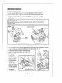
1
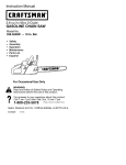
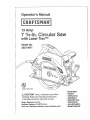
13 Amp
7 14°in° Circular
with Laser Trac T_'_
Model No.
320.10871
(9
DOUBLE
INSULATED
o WARRANTY
Z_ CAUTION
Read, understand and follow
all Safety Rules and Operating Instructions
in this Manual before using this product.
Sears, Roebuck and Co.,
Hoffman Estates, IL 60179 U.S.A.
Visit our Craftsman website: www.craftsman.com
I
I
• SAFETY
o UNPACKING
o ASSEMBLY
° DESCRIPTION
,' OPERATION
,' ADJUSTMENTS
• MAINTENANCE
Warranty
..............................................................................
Safety
Symbols
Safety
Instructions
Glossary
Assembly
............................................................................
.........................................................................................
Description
Operation
.........................................................................
............................................................................
Adjustments
Maintenance
Troubleshooting
Accessories
Sears
....................................................................
of Terms .........................................................................
Unpacking
Repair
.......................................................................
.........................................................................
...........................................................................
ONE YEAR
2
Page
3
Pages
4 - 11
Pages
11 - 12
Pages
12 - 13
Pages
13-
Pages
15 - 17
14
Pages
17 - 27
Page
28-
Pages
29 - 30
29
.........................................................................
Page
30
.................................................................................
Page
30
Pages
31 - 34
Parts ............................................................................
Repair
Page
Parts
Phone
Numbers
FULL WARRANTY
.............................................
ON CRAFTSMAN
Back
Cover
_ PRODUCT
If this Craftsman product fails due to a defect in material or workmanship
within one year from the date of purchase, RETURN ITTOTHE
NEAREST SEARS STORE OR PARTS AND REPAIR CENTER OR
OTHER CRAFTSMAN OUTLET IN THE UNITED STATES FOR FREE
REPAIR (OR REPLACEMENT IF REPAIR PROVES IMPOSSIBLE).
This warranty does not include expendable
batteries, bits or blades.
parts such as lamps,
If this Craftsman product is used for commercial or rental purposes,
this warranty applies for only 90 days from the date of purchase.
This warranty gives you specific legal rights, and you may also
have other rights, which vary from state to state.
Sears, Roebuck and Co., Hoffman Estates, IL 60179
SAVE THESE INSTRUCTIONS!
READ ALL INSTRUCTIONS!
2
The purposeof safetysymbolsis to attractyourattentionto possibledangers.
The safetysymbols,andtheexplanations
withthem,deserveyourcareful
attentionandunderstanding.
ThesymbolwarningsDONOTby themselves
eliminateanydangerTheinstructionsandwarningstheygiveare nosubstitutes
for properaccidentpreventionmeasures
z_ WARNING:
BE SURE to read and understand all safety instructions in ,,
this ,manual, including all safety alert symbols such as "DANGER", "WARNING
I and CAUTION , BEFORE using this saw. Failure to follow all instructions
_
below may result in electric shock fire and/or serious personal
SYMBOL
Z_
injury,
.
MEANING
SAFETY ALERT SYMBOL:
Indicates DANGER,WARNING,OR
CAUTION, May be used in conjunction
with other symbols
or pictographs,
DANGER: Failure to obey this safety warning WILL result
in death or serious injury to yourself or to ethers. Always
follow the safety precautions to reduce the risk of fire,
electric shock and personal injury.
[ Z_WARNING
Failure to obey this safety warning CAN result in death or
] serious injury to yourself or to others. Always follow the
safety precautions to reduce the risk of fire, electric shock
and personal injury.
I
_
CAUT_ON
]
!
I
J
obey
this or safety
MAY
result
in
personal
injury toto yourself
others warning
or property
damage,
Always
follow the safety precautions to reduce the risk of fire,
electric shock and personal injury.
Failure
DAMAGE PREVENTION AND INFORMATION MESSAGES
These inform user of important information and/or instructions that could lead to
equipment or other property damage if not followed. Each message is preceded
by the word "NOTE:" as in the example below:
NOTE: Equipment and/or property damage may result if these instructions
are not followed.
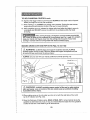
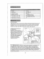
WEAR YOUR
z_WARNING:
The operation of any tool with a cimular
blade can result in foreign objects being thrown into
your eyes, which can result in severe eye damage.
Before beginning power tool operation, ALWAYS wear
safety goggles or safety glasses with side shield and
a full-face shield when needed. We recommend a Wide
Vision Safety Mask for use over eyeglasses or standard
safety glasses with side shield, available at Sears Stores
or other Craftsman Outlets.
]
z_WARNING:
BE SURE to read and understand all instructions
in this
manual before using this circular saw. Failure to follow all instructions may
result in hazardous radiation exposure, electric shock, fire and/or serious
personal injury.
SAFETY
PRECAUTIONS
FOR LASERS
This circular saw has a built-in laser light The laser is a Class Ilia and emits output power
of a maximum 1 mW and 635-665nm wavelengths These lasers do not normally present
an optical hazard However, DO NOT stare at the beam as this can cause flash blindness
The following label is on your tool.
It indicates where the saw emits the
laser light. BE AWARE of the laser light
location when using, ALWAYS MAKE
SURE that any bystanders in the vicinity
of use are made aware of the dangers
of looking
Exposure.
directly
into the laser.
DO NOT stare into beam. Only turn laser beam on when the saw
[ is/_,WARNING:
LASER RADIATION. Avoid Direct Eye
on the workpiece. LASER
Class LIGHT.
Ilia laser,
other than those specified in this manual may result in hazardous radiation
Use of controls, adjustments or performance of procedures
[ exposure.
_WARNING:
or transits
view
laserinstruments
beam will increase
[ telescopes
Z_WARNBNG:
Thetouse
of the
optical
such as, eye
but hazard.
not limited to,
1 DO NOT remove or deface any product labels. Removing
increases the risk of exposure to laser radiation.
product
labels
2, The laser beam can be harmful to the eyes. ALWAYS avoid direct eye exposure.
DO NOT look directly into the laser beam output aperture during operation DO NOT
project the laser beam directly into the eyes of others. Turn laser on ONLY when
making cuts.
3 Laser enhancing safety glasses are included to enhance the laser beam in bright light
conditions DO NOT wear these glasses if they interfere with the safe operation
of this saw.
4, The laser on the circular saw is not a toy. ALWAYS keep out of the reach of
children, The laser light emitted from this device SHOULD NEVER be directed
towards any person for any reason,
5. BE SURE the laser beam is aimed at a workpiece (such as wood or rough
coated surfaces) that does not have a reflective surface
4
6. DO NOT use on surfaces such as sheet steel that have a shiny, reflective surface.
The shiny surface could reflect the beam back at the operator, Be aware that laser
light reflected off of a mirror or any other reflective surfaces can also be dangerous
7o ALWAYS turn the laser beam off when not in use. Leaving the tool on increases
the risk of someone inadvertently staring into the laser's beam.
"1
when using this laser. Use of this feature in any manner other than what appears
/_
CAUTION:
only theradiation
instructions
contained in this manual
in this
manual mayALWAYS
result infollow
a hazardous
exposure,
J
/
8. DO NOT attempt to modify the performance of this laser device in any way,
This may result in a dangerous exposure to laser radiation.
9. ALWAYS use only the accessories that are recommended by Sears for use
with this producL Use of accessories that have been designed for use with
other laser tools could result in serious injury.
10. For further information regarding lasers, refer to ANSI-Z136.1
The STANDARD FOR THE SAFE USE OF LASERS, available
from the Laser Institute of America (407) 380-1553.
WORK
AREA
SAFETY
1_ Keep your work area clean and well lit. Cluttered workbenches and dark areas
invite accidents°
2. DO NOT operate power tools in explosive atmospheres, such as in the presence
of flammable liquids, gases, or dust. Power tools create sparks which may ignite
the dust or fumes,
3. Keep bystanders, children and visitors away while operating a power tool.
Distractions can cause you to lose control
4. Make your workshop childproof
tools away when not in use.
with padlocks and master switches_ Lock
5. MAKE SURE the work area has ample lighting so you can see the work and that
there are no obstructions that will interfere with safe operation BEFORE using your saw
PERSONAL
SAFETY
1. KNOW your power tool. Read the operator's manual carefully. Learn the saw's
applications and limitations, as well as the specific potential hazards related to this tool.
2. STAY ALERT, watch what you are doing and use common sense when operating
a power tool.
3. DO NOT use tool while tired or under the influence of drugs, alcohol or medication.
A moment of inattention while operating power tools may result in serious personal injury.
4. DRESS properly. DO NOT wear loose clothing or jewelry. Pull back long hair, Keep
your hair, clothing, and gloves away from moving parts° Air vents often cover moving
parts and should also be avoided. Loose clothing, jewelry or long hair can be caught
in moving pads°
5
PERSONAL
SAFETY
cont.
5. AVOID accidental starting. Re sure switch is in "OFF" position before
plugging in DO NOT carry tools with your finger on the switch. Carrying tools
with your finger on the switch or plugging in tools that have the switch in the
"ON" position invites accidents
6. REMOVE adjusting keys or wrenches before turning the tool "ON". Awrench
that is left attached to a rotating part of the tool may result in personal injury,
7 Do not overreach. Keep proper footing and balance at all times. Proper
footing and balance enables better control of the toot in unexpected situations.
8. ALWAYS SECURE YOUR WORK. Use clamps or a vise to hold work when
practical It is safer than using your hand and frees both hands to operate tool.
9 USE SAFETY EQUIPMENT, Always wear eye protection Dust mask, non-skid
safety shoes, hard hat, or hearing protection must be used for appropriate
condilions.
10o DO NOT USE ON A LADDER or unstable support. Stable footing on a solid
surface enables better control of the tool in unexpected situations,
TOOL
USE AND
CARE SAFETY
_, WARNING : BE SURE to read and understand all instructions before
operating this saw. Failure to follow all instructions
listed below may result in
electric shock, fire and/or serious personal injury.
1, ALWAYS use clamps or other practical ways to secure and support the
workpiece to a stable platform. Holding the work by hand or against your body
is unstable and may lead to loss of control
2. DO NOT force the tool. Use the correct tool and blade for your application,
The correct tool and blade will do the job better and safer at the rate for which it is
designed,
3 DO NOT use the tool if switch does not turn it "On" or "Off", Any tool that
cannot be controlled with the switch is dangerous and must be repaired.
4 DISCONNECT the plug from the power source before making any adjustments,
changing accessories or storing the tool, Such preventive safety measures
reduce the risk of starting the tool accidentally.
5. NEVER leave the tool running.
it comes to a complete stop.
ALWAYS turn it off. DO NOT leave the tool until
6. STORE idle tools out of the reach of children and other untrained
Tools are dangerous in the hands of untrained users.
persons,
7o MAINTAIN tools with care. Keep cutting tools sharp and clean. Properly
maintained tools with sharp cutting edges are less likely to bind and are easier to
control.
8 CHECK for misalignment
or binding of moving parts, breakage of parts, and
any other condition that may affect the tool's operation If damaged, have the tool
serviced before using. Many accidents are caused by poorly maintained tools,
9. USE ONLY accessories that are recommended for this tool, Accessories that
may be suitable for one tool may become hazardous when used on another tool.
6
ELECTRICAL
SAFETY
Z_WARNING:
Do not permit fingers to touch the terminals of plug when
installing or removing the plug from the outlet.
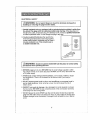
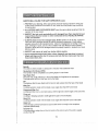
1. Double insulated tools are equipped with a polarized plug (one blade is wider than
the other).Thls plug will fit in a polarized outlet only one way. If the plug does not
fit fully in the outlet, reverse the plug If it still does not fit, contact a qualified electrician
to install a polarized outlet. Do not change the plug in any way.
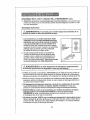
2. Double insulation[] eliminates the need for the
three-wire grounded power cord and grounded
power supply system. Applicable only to Class II
(double-insulated) tools. This circular saw is
a double insulated tool.
@
Cover or
®
Outlet
Box _
Grounded
I-_WARNING:
Double insulation
DOES NOT take the place of normal safety
precautions when operating this tool.
3, BEFORE plugging in the tool. BE SURE that the outlet voltage supplied is within
the voltage marked on the tool's data plate. DO NOT use "AC only" rated tools with
a DC power supply
4, AVOID body contact with grounded surfaces, such as pipes, radiators, ranges
and refrigerators. There is an increased risk of electric shock if your body is
grounded.
5 DO NOT expose power tools to rain or wet conditions or use power tools in
wet or damp locations. Water entering a power tool will increase the risk of
electric shock.
6, INSPECT tool cords for damager Have damaged tool cords repaired at a Sears
Service Centsr, BE SURE to stay constantly aware of the cord location and keep
it well away from the moving blade
7, DO NOT abuse the cord, NEVER use the cord to carry the toot by or pull the
plug from the outlet. Keep cord away from heat, oil, sharp edges or moving parts
Replace damaged cords immediately Damaged cords increase the risk of electric
shock
7
EXTENSION CORDS
Use a proper extension cord, ONLY use cords listed by Underwriters Laboratories
(UL). Other extension cords can cause a drop in fine voltage, resulting in a loss of
power and overheating of tool For this tool an AWG (American Wire Gauge) size of
at least 14-gauge is recommended for an extension cord of 25-ft or less in length
Use 12-gauge for an extension cord of 50-ft Extension cords 100-ft. or longer are not
recommended. Remember, a smaller wire gauge size has greater capacity than
a larger number (14-gauge wire has more capacity than 16-gauge wire; 12-gauge
wire has more capacity than 14-gauge) When in doubt use the smaller number
When operating a power tool outdoors, use an outdoor extension cord marked
"W-A" or "W" These cords are rated for outdoor use and reduce the risk of electric
shock.
Z_ CAUTION:
Keep the extension cord clear of the working area. Position
the cord so that it will not get caught on lumber, tools or other obstructions
while you are working with a power tool,
Z_WARNING:
Check extension cords before each use. If damaged
replace immediately. Never use tool with a damaged cord since touching
damaged area could cause electrical shock, resulting in serious injury.
SAFETY SYMBOLS
the
FOR YOUR TOOL
The label on your tool may include the following
symbols.
V .......................................................
Volts
A .................................
Amps
Hz .........................................
Hertz
W.............................................................
Watts
min ......................................
Minutes
_. ...............................
Alternating current
..............................
Direct current
no .......................................................
No-load speed
[] ............................................................
Class II construction, Double insulated
/min ....................................
Revolutions or Strokes per minute
z_, .............................
Indicates danger, warning or caution
It means attention! Your safety is involved
SERVICE SAFETY
I If any part of this saw is missing or should break, bend, or fail in any way;
or should any electrical component fail to perform properly: SHUT OFF
the power switch and lemove the saw plug from the power source and have
the missing, damaged or failed parts replaced BEFORE resuming operation
2, Tool service must be performed only at a Sears Parts and Repair Center,
Service or maintenance performed by unqualified personnel could result in
a risk of injury
3 When servicing a tool, use only identical replacement parts, Follow
instructions
in the maintenance section of this manual. Use of unauthorized
parts or failure to follow maintenance instructions may create a risk of electric
shock or injury
8
1
1
SAFETY RULES FOR CIRCULAR
SAWS
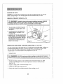
Keep hands away from cutting area and blade. Keep your
second hand on the auxiliary handle or motor housing. If both hands are holding
the saw, the blade cannot cut them.
Z_ CAUTION:
Blades coast after saw is switched off.
t KEEP your body positioned to eithei side of the saw blade and not in direct
line with the saw blade. Kickback could cause the saw to jump backwards (See
"Kickback What Causes It and Ways to Prevent It" on pages 18 and I9)
2. DO NOT reach underneath the work. The guard cannot protect you from the blade
beneath the workpiece.
DOES NOT cover the blade on the underside of the workpiece (Pgo 17 Fig. 4).
_ALWAYS keep your When
through
a workpiece,
the lower
blade guard
handssawing
and fingers
away
from the cutting
area.
3. CHECK lower guard for proper closing BEFORE each use. DO NOT operate the saw
if the lower guard does not move freely and close instantly. Never clamp or tie the
lower guard in the open position. If the saw is accidentally dropped, timelower guard may
be bent. Raise the lower guard with the retracting lever The guard is operating properly
when it moves freely, does not touch the blade or any other part in all angles and depths
of cut, and readily returns to the closed position
4 CHECK the operation and condition of the lower guard spring, If the guard and the
spring are not operating properly, they MUST BE serviced before use. The lower
guard may operate sluggishly, due to damaged pads, gummy deposits, or a buildup of
debris DO NOT operate your saw until the damage has been repaired or replaced.
5 The lower guard should be retracted manually ONLY for making special cuts, such
as pocket or compound cuts. ALWAYS raise the lower guard by retracting its lever.
As soon as the blade enters the material, the lower guard MUST be released. For al!
other sawing, the lower guard should operate automatically
6 ALWAYS make sure that the lower guard is covering the blade BEFORE placing the
saw down on a work bench or floor. An unprotected moving blade wil! cause the saw to
walk backwards, cutting whatever is in its palh Make note of the time it takes for the blade
[o stop spinning alter the switch is released.
7 NEVER hold the piece being cut in your hands or across your legs. tt is important to
support the workpiece properly in order to minimize body exposure, blade binding, or toss
of control.
8 HOLD TOOL by insulated gripping surfaces (handles) when performing an operation
where the cutting tool may contact hidden wiring or its own cord. Contact with a "live"
wire will make the exposed metal parts of the tool "live" and shock the operator
9 ALWAYS clamp the workpiece
securely so it will not move when making the cut
10 When ripping, ALWAYS USE a rip fence or straight edge guide. This improves the
accuracy of the cut and reduces the chance of the blade binding.
11. ALWAYS USE blades that have the correct size and shape (diamond vso round) arbor
holes. Blades that do not match the mounting hardware of the saw will run erratically and
cause loss of control
9
I
I
1
I
SAFETY RULES FOR CIRCULAR
!2
SAWS cont,
NEVER use damaged or incorrect blade washers or bolts. The blade washers
and bolts were specially designed for your saw, for optimum performance and
safety of operation
13 NEVER cut more than one piece at a time. DO NOT STACK more than one
workpiece on the worktable at a time.
!4. AVOID awkward operations and hand positions
cause your hand to move into the blade.
15 NEVER reach into the cutting
where a sudden slip could
path of the blade.
/fX WARNING: Use of this product can generate dust containing chemicals
known to cause cancer, birth defects or other reproductive harm. Some examples of
these chemicals are:
o Lead from lead-baaed paints.
• Crystalline silica from bricks and cement and other masonry products_
. Arsenic and chromium, from chemically treated lumber.
Your risk from these exposures varies, depending upon how often you do this
type of work.To reduce your exposure to these chemicals:
• Work in a well-ventilated area.
° Work with approved safety equipment, such as those dust masks that are specially
designed to filter out microscopic particles.
Avoid prolonged contact with dust from power sanding, sawing, grinding, drilling
and other construction activities. Wear protective clothing and wash exposed
areas with soap and water.
Allowing dust to get into your mouth, eyes, or lay on the skin may promote absorption
of harmful chemicals
WARNING: Use of this tool can generate and/or disburse dust, which may
cause serious and permanent respiratory or other injury. Always use NIOSH/OSHA
approved respiratory protection appropriate for the dust exposure. Direct particles
away from face and body.
ADDITIONAL
RULES
FOR SAFE OPERATION
WARNING: BE SURE to read and understand all instructions, Failure
to follow all instructions listed below may result in electric shock, fire and/or
serious personal injury.
1 Know your power tool. Read operator's manual carefully. Learn the applications
and limitations, as well as the specific potential hazards related to this tool Following
this rule will reduce timerisk of electric shock, fire or serious injury
2 ALWAYS wear safety glasses or eye shields when using this saw, Everyday
eyeglasses have only impact-resistant lenses; they are NOT safety glasses
3 PROTECT your lungs. Wear a face mask or dust mask if the operation is dusty
10
ADDITIONALRULESFORSAFE OPERATIONcont.
4 PROTECT your hearing. Wear appropriate personal hearing protection during use
Under some conditions and duration of use, noise from this product may contribute
to hearing loss
5 ALL VlSTORS AND BYSTANDERS MUST wear the same safety equipment that the
operator of the saw wears,
6 INSPECT the tool cords periodically and if damaged have them repaired at your
nearest Sears Service Center or other Authorized Service Facility. BE AWARE
of the cord location,
7, ALWAYS check the tool for damaged parts. Before further use of the tool, a guard or
other part that is damaged should be carefully checked to determine if it will operate
properly and perform its intended function Check for misalignment or binding of moving
parts, breakage of parts, and any other condition that may affect the tool's operation
A guard or other part that is damaged should be properly repaired or replaced at a Sears
Service center
8 INSPECT and remove all nails from lumber before sawing,
9, SAVETHESE INSTRUCTIONS, Refer to them frequently and use them to instruct
others who may use this tool, If someone borrows this tool, make sure they have
these instructions also,
Spindle
The shaft on which a blade or cutting tool is mounted Also called the Arbor
Revolutions Per Minute (RPM)
The number of turns completed by a spinning object in one minute
Saw Blade Path
The area over, under, behind or in front of the blade, as it applies to the workpiece.
That area which will be or has been cut by the blade,
Set
The distance that the saw blade tooth is bent (or set) outward from the face of the blade
Miter Cut
A cutting operation made with the blade at any angle other than 900 to the fence
Compound Miter Cut
A compound miter cut is a cut made using a miter angle and a bevel angle at the same time,
Cross cut
A cutting or shaping operation made against the grain of the workpiece
Bevel Cut
A cutting operation made with the blade at any angle other than 90° to the miter table,
Dado Cut
A non-through cut which produces a square-sided notch or trough in the workpiece
(requires special blade).
Chamfer Cut
A cut removing a wedge from a biock of wood so the end (or part of the end) is angled
at other than 90°
11
I
I
Ripping or Rip Cut
A cutting operation along the length of the workpiece
Freehand Cut
Performing a cut without using a fence, miter gauge, fixture, work clamp, or other
proper device to keep the workpiece flora twisting or moving during the cut.
Through Sawing
Any cutting operation where the blade extends completely through the thickness of
the workpiece
Non-Through Cuts
Any cutting operation where the blade does not extend completely through the
thickness of the workpiece, like a dado cut
Leading End
Tile end of the workpiece pushed into toot first
Kerr
The material removed by the blade in a through cut or the slot produced by the blade
in a non-through or partial cut
Kickback
A hazard that can occur when tile blade binds or stalls, throwing the workpiece back
toward operator
Werkpiece or Material
The item on which the cutting operation is being done The surfaces of a workpiece
are commonly [eferred to as faces, ends and edges
Gum
A sticky, sap-based residue from wood products,
Resin
A sticky, sap-based substance that has hardened
when you are assembling parts, making adjustments,
installing or removing
blades, cleaning or when it is not in use. Disconnecting
the saw will prevent
WARNING:
should
NEVER
connectedinjury.
to the power source
accidental
starting, Your
whichsaw
could
cause
seriousbe personal
1 Included with your circular saw is the cutting blade (unassembled) packed separately
Also a blade wrench stored in the base, for use installing or changing the blade, an
edge guide and a pair of Laser enhancing safety glasses used to enhance the laser
beam in bright light conditions
2 Inspect tile saw carefully to make sure that no breakage or damage has occurred during
shipping, If any of the items mentioned are missing (refer to PARTS LIST illustration see
Fig1 page 13), return tile saw to your nearest Sears store or Craftsman outlet to have
the saw replaced
/
in the power cord or operate saw until the broken or missing parts are replaced.
WARNING: If any parts are broken or missing, DO NOT attempt to plug
Failure to do so could result in possible serious injury.
12
]
]
-7
I
I
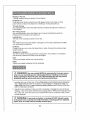
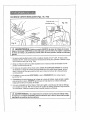
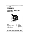
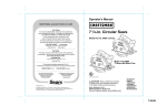
PARTS LIST
(Fig. 1)
4. Blade Wrench
I[ !
(for changing
I_J
the blade)
5_ Laser Enhancing
_/..,F
/
Safety Glasses
(-/ _11
.(7,U
(for enhancing laser)
"_----"
(unassembled,
install onto saw)
6. Operator's
Manual
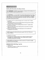
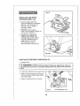
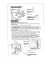
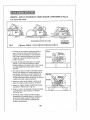
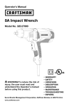
INSTALLING
THE BLADE
(Figs. 2 and 2a)
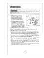
Carefully remove the blade from its packing, inspect it to be sure that it is not cracked
or damage&
1, Saw should not be plugged into power source,
powerWARNING:
source BEFORE
parts,injury,
makingALWAYS
adjustments
or installing
z_
To assembling
prevent personal
disconnect
the plugblades.
from
2. Place saw on its side on a flat surface
3 To loosen the depth-of-cut ad ustment lever, raise the saw up all the way and tighten lever
This gives you easier access to blade mounting area (see Fig 2a)
4
Place saw upright, on its base and on a flat surface (see Fig 2a).
5 To loosen the spindle clamping screw "A", depress the spindle lock button (see Fig 2)_
Place the blade wrench on the spindle clamping screw "A", Move the wrench back and
forth until you feel the spindle lock button depress further and it locks the blade in
position so the spindle clamping screw can be removed Keeping the spindle lock button
firmly depressed, turn the spindle screw
counterclockwise to remove
__j__
_
\J
Spindle
__
Lock Button
Depth-oI-Cut
Adjustment Lever
)uter "D" Washer
Fig. 2a
=A" Spindle
Clamping Screw
Blade Rotation
teeth point up at front
13
]-
INSTALLING
THE
BLADE
cont.
(Figs.
2 and 2a)
L_ WARNING:
BE SURE to wear protective work gloves while handling a saw
blade.The blade can injure unprotected hands,,
Z_ WARNING: A 7 1/4-inch blade is the maximum blade capacity of your saw, A
larger than 71/4-inch blade will come in contact with the blade guards. Also, NEVER
use a blade that is so thick that it prevents the outer blade washer from engaging
with the flat side of the spindle,, Blades that are too large or too thick can result in
an accident causing serious injury.
6. Completely remove the spindle clamping screw "A" and the outer "D" washer
(see Fig, 2a),
7,. The remaining washer is the inner bushing washer that fits around the spindle
shaft and it does not need to be removed,
8,, Put a drop of oil onto the inner bushing washer and outer "D" washer where
they will touch the blade.
9. Raise lower blade guard using the blade guard lever and hold it in the raised
position for the next step.
10, Place the saw blade inside the lower blade guard, onto the spindle shaft
and against the inner bushing.
/
shown
in (Fig.
NOTE: The
teeth2a),
of the blade should point upward at the front of the saw as
J
/
11,. Replace the "D" washer,
12. Firmly hold down spindle lock button as you replace the spindle screw and
hand tighten it in a clockwise direction, Then use blade wrench to tighten
the spindle clamping screw thoroughly,
with
theNEVER
flat side
of athe
spindle.
NOTE:
use
blade
that is too thick to allow the"D"washer
REIVIOVING
THE BLADE
(Figs.
2 and 2a)
1, Unplug the saw,
2, Follow steps 2, through 6, of "INSTALLING
remove the blade (see Fig. 2a).
14
THE BLADE" and
to engage
I
-I
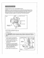
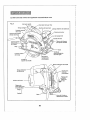
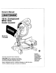
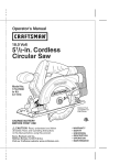
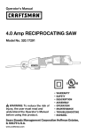
KNOW YOUR CIRCULAR
SAW (Fig, 3)
NOTE: Before attempting to use your saw, familiarize
operating features and safety requirements.
yourself with all of the
Your circular saw has a precision-built eiectdc motor and it should only be connected to
a 120-volt, 60-Hz AC ONLY power supply (normal household current). DO NOT operate
on direct current (DC). This large voltage drop will cause a loss of power and the motor
will overheat, If the saw does not operate when plugged into correct 120-volt, 60-Hz AC
ONLY outlet, check the power supply The saw has an 8-fL, 2-wire power cord
(no adapter needed).
This Circular
Saw has the following
features:
1.13 Amp, 5000 RPM (no-load speed) motor provides the power and torque for fast,
sure cuts in wood, plywood, hardboard and wood-base materials.
2. LaserTrac T_ The unique, innovative feature for accurate, efficient
cutting!
3. LED WORKLIGHT illuminates cutting area for easy visibility.
This light stays "On" when saw is plugged into power source.
4. Quick depth-of-cut
adjustments
2 3le-in. thick at 90;
with a maximum depth of cut:
1 13hs-in. thick at 45 °
5. Easy to read bevel cut scale adjusts from 0 ° to 52 ° bevel capacity.
6. Die-cast aluminum
blade guards for extra strength and durability,
7. Extended length, trigger switch for maximum control and comfort.
Squeeze for power "ON", release for power "OFF"°
8. Large stamped
Steel Base provides a stable work surface for better saw control.
9. Soft-grip ergonomically
designed contoured rear handle and front assist handle
for positive gripping, control, balance and comfort.
10. Includes
Craftsman ® 24 tooth carbide-tipped
11. Top mounted
blade spindle
steel general purpose blade.
lock for easy blade changes.
12. Includes
edge guide to help produce accurate cuts.
13_ Sawdust
ejection
14_ Permanently
chute helps direct dust and chips away from operator.
lubricated
15. Durable machined
'100% ball bearings
for smooth operation and tong life,
gearing for efficient power transmission.
15
]
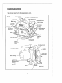
This Circular
Saw has the following features
Fig, 3
cont.
TriggerSwitch
Rear Handle
Laser Light Aperture
Upper
Blade Guard
Front Assist Handle
Motor Housing
Lower Blade
Guard Lever
I Scale
Bevel Adjustment
Locking Lover
Base
_oge Guide
Locking/retaining
Screw
Mounting Slots
for Edge Guide
Spindle
Clamping
Screw
Spindlo Lock Button
Cut Scale
Lower Blade
Motor Housing --
Depth-of-Cut
Adjustment Lever
Loosen _
Tighten 4"
Base
-Blade Wrench
(storesin base)
16
Input
13 Amps
Rating
120V, 60HZ AC
No Load Speed
5000
Blade Diameter
71/,_-in. (184mm)
Cutting Depth at 90 °
23/a-in. (60.33mm)
RPM
Cutting Depth at 45 °
113/1G-in. (46.03mm)
Maximum Bevel Angle
52 °
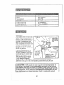
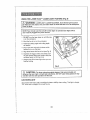
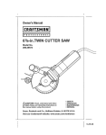
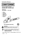
SAW BLADES
All saw blades need to be kept clean,
sharp and properly set in order to cut
efficiently Using a dull blade places a
heavy load on the saw and increases
the danger of kickback Keep extra
blades on hand, so sharp blades are
always available Gum and wood pitch
hardened on the blade slows the saw
down Use gum and pitch remover,
hot water or kerosene to remove them,
DO NOT use gasoline
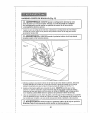
Fig. 4
r Blade
BLADE GUARD SYSTEM (FiG 4)
The lower blade guard, attached to
your circular saw, is there for your
protection and safety, It should
NEVER be altered for any reason,
If it becomes damaged or begins
to return slowly or sluggishly,
DO NOT operate your saw until the damage has been repaired or replaced.
ALWAYS leave the guard in its correct operating position when using the saw.
CAUTION: NEVER use the saw when the guard is not operating properly. The
guard should be checked for correct operation before each use, If you drop your saw,
check the lower blade guard and bumper for damage at all depth settings before using,
NOTE: The guard is operating properly when it moves freely and then readily returns to
the closed position. If for any reason your lower blade guard and bumper does not close
freely, take the saw to your nearest Sears Repair Center for service before using it.
17
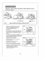
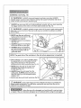
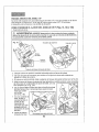
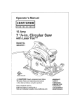
KICKBACK...WHAT
CAUSES
IT AND WAYS TO HELP
PREVENT
IT (Fig. 5)
The Causes of Kickback
Correct Blade Depth
Blade is Set Too
Deep
Fig. 5
1 Kickback is a sudden reaction to a pinched,
bound or misaligned saw blade, which
causes an uncontrolled saw to lift up and
out of the workpiece and toward
the operator.
Fig. 6
2 When the blade is pinched or bound tightly by the
kerr closing down, the blade stalls and the motor
reaction drives the unit rapidly back towards the
operator
3 If the blade becomes twisted or misaligned in the
cut, the teeth at the back edge of the blade can dig
into the top surface of the wood This causes the
blade to climb out of the kerr and
jump back towards the operator
4 Sawing into knots or nails in the workpiece
can cause Kickback
5 Sawing into wet or warped lumber can
cause Kickback, (see Fig. 6a)
6 Forcing a cut, or not supporting the workpiece
correctly can cause Kickback (see Fig 6a)
7 Kickback is a result of tool misuse and!or incorrect
operating procedures or conditions
It can be avoided by taldng the proper
precautions, on page 19,
18
Right _
Fig,
--1
I
I
Ways to Help Prevent Kickback
or the saw stalls. Kickback could cause you to lose control of the saw_ Loss of control
_
ALWAYS release trigger switch immediately if the blade binds
can lead to serious injury.
ALWAYS maintain a firm grip with
both (see Fig 7) hands on the saw
and position your body and arms to
allow you to resist Kickback forces
Kickback forces can be controlled by
the operator, if the proper precautions
are taken
2 If the blade is binding, or when you are
interrupting a cut for any reason, ALWAYS
release the trigger and hold the saw
motionless in the material until the blade
comes to a complete stop NEVER attempt
to remove the saw from the work or pull the
saw backward while the blade is in motion,
or Kickback may occur, CHECK and take
corrective action to eliminate the cause of blade binding
3 Inspect the workpiece for knots or nails before cutting Never saw into a knot or nail
4 DO NOT cut warped or wet lumber (see Fig 6a)
5 ALWAYS support large panels to minimize the risk of blade pinching and Kickback Large
panels tend to sag under their own weight (see Fig 6a) Supports MUST be placed under
the panel, one near the line of cut and one near the edge of the panel (see Fig 6)
6 When restarting the saw in the workpiece, CENTER the blade in the kerf and check to be
sure that the saw teeth are not engaged into the material, If the saw blade is binding, it may
walk up or Kickback from the workpiece when the saw is restarted
7 DO NOT use a dull or damaged blade, Unsharpened, improperly set, or gummed-up blades
produce narrow kerr which causes excessive friction, blade binding and Kickback
8 KEEP the blade at the correct depth setting. The depth setting should not exceed 1/4-inch
betow the material being cut (see Fig. 5). BE SURE that the blade depth and adjusting
locking levers are tight and secure BEFORE making a cut, If blade adjustment shifts while
cutting it may cause binding and Kickback,
9 USE EXTRA CAUTION when making a "Pocket Cut" into existing walls or other blind areas
The protruding blade may cut objects that can cause Kickback
19
I
I
1
..........................................
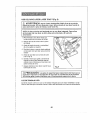
MAKING
DEPTH-OF-CUT
ADJUSTMENTS
(Fig. 8)
ALWAYS use the correct blade depth setting The correct blade depth setting for all cuts
should net be more than 1/4-inch below the material being cut (see Fig 5) Allowing more
depth will increase the chance of kickback and cause the cut to be rough Your saw is
equipped with a deptb-oFout scale that provides increased depth-of-cut accuracy
The depth-of-cut scale is located on the inside back of the upper blade guard
Fig, B
plh-of-Cul Scate
Raise the Saw
Depth-of-CutLever
\\
Lower the Saw
for Adiusting_
i
TO SETTHE
BLADE
DEPTH (Fig. 8a)
1 Unplug the saw,
,4k, WARNING:
ALWAYS unplug saw before making any adjustments, Failure to
unplug the saw could result in accidental starting which can cause serious personal
injury.
2 Raise the depth-of-cut adjustment
lever to loosen the base (see Fig, 8).
)
3. Determine the desired depth of cut
4 Locate the depth-of-cut scale oil the
back of the upper blade guard
(see Fig, 8a)
Adjusting
_
5 Hold the base of the saw flat against
the edge of the workpiece and then
raise or lower the saw until the indicator
mark on the bracket aligns with the
notch on the blade guard at
the desired depth-of-cut mark,
6 Tighten depth-of-cut adjustment lever
Fig_ 8a
2O
--[
/
,,,-
iNIllll
of-t t
9, -De,,
USING THE
LASER
TRAC _ LASER
LIGHT
FEATLIRE
(Fig. 9)
Z_ WARNING:
LASER LIGHT. LASER RADIATION, Avoid Direct Eye Exposure,
DO NOT stare into beam. Only turn laser beam on when the saw is on the workpiece.
Class ilia laser_
NOTE: Your circular saw has a built-in laser light. To activate laser light switch,
saw must be plugged into power source.
DO NOT turn the laser beam on until the saw
is on the workpiece
2r Mark the line of cut on the workpiece
Adjust the cutting angle and cutting depth
as needed
4 Plug in the saw and push the laser switch
forward to turn on the laser
5 Align laser beam with line-of-cut (see Fig 9)
6 Squeeze the trigger switch and slowly push
the saw forward using both hands Keep the
red laser beam on the line-of-cut
Always shut off the laser light when you are
finished cutting
Fig. 9
e_nh ance
CAUTION:
The laser enhancing safety glasses that were included will
the laser light in bright light conditions. DO NOT wear these glasses if they
interfere with the safe operation
of this saw,
LED WORKLIGHT
Your circular saw has a built-in worklight for better visibility when cutting This light is always
"ON" when saw is plugged into power source
21
]
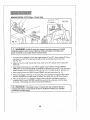
STARTING
A CUT (Fig. 10)
maintain proper control of saw, Failure to clamp and support workpiece
and loss of
I control
_ WARNING:
support workpiece securely. ALWAYS
of saw could ALWAYS
result in clamp
seriousand
injury,
1. ALWAYS use your saw with your hands positioned correctly, with one hand operating
the trigger switch and the other on the front assist handle (see Fig. 10).,
and easier. Loss of control of the saw could cause an accident resulting in possible
Z_ WARNING:
ALWAYS maintain proper control of the saw to make sewing safer
serious
injury.
2. NEVER use the saw with your
hands positioned as shown in Fig, 11
To Help Maintain Control:
3. ALWAYS support the workpiece
near the cuL
4. ALWAYS support the workpiece
so the cut will be on your right.
5. ALWAYS clamp the workpiece
so it will not move during the cut,,
Place the workpiece with the
good side down,
I NOTE: The good side of the workpiece
is the side where appearance
is important.
6. Before starting a cut, draw a guideline along
the desired line of cut, then place the front
edge of the saw base on that part of the
workpiece that is solidly suppoded (see Fig 10)
7. NEVER place the saw on the part of the
workpiece that will fall off when the cut
is made (see Fig. 11).
8. ALWAYS keep the cord away from the
cutting area. ALWAYS place the cord so it
does not hang up on the workpiece when
making a cut.
g Hold the saw firmly with both hands (see Fig 10)_
Fig. 11
z_ WARNING:
If the cord hangs up on the workpiece during a cut, release the
trigger switch immediately. To avoid injury, unplug the saw and move the cord to
prevent it from hanging up again.
I_
Using the saw with a damaged cord could result in serious injury
or death. If the cord has been damaged, have it replaced before using the saw again,,
22
]
TO HELP MAINTAIN
CONTROL
cont.:
t0. Squeeze the trigger switch to start the saw. ALWAYS let the blade reach full speed
before you begin the cut into the workpiece.
11_ When making a cut, ALWAYS use steady, even pressure. Forcing the saw causes
rough cuts and could shorten the life of the saw or cause Kickback.
12. After completing your cut, release the trigger switch and allow the blade to come to
a complete stop, DO NOT remove the saw from the workpiece while the blade
is moving_
When sawing through a workpiece, the lower blade guard DOES
NOT cover the blade on the underside of the workpiece (see Fig. 4, page 17). ALWAYS
keep your hands and fingers away from the cutting area. Any part of your body
coming in contact with the moving blade will result in serious injury.
MAKING
CROSS
CUTS AND
RIP CUTS
(Figs.
12 and 12a)
z_ WARNING: ALWAYS clamp and support workpiece securely. ALWAYS
maintain proper control of saw. Failure to clamp and support workpiece and !0ss
of control of saw could result in serious injury.
1 ALWAYS use your saw with your hands positioned correctly (see Fig 12).
Line of Cut
Fig. 12a
Fig. 12
Z_ WARNING: ALWAYS maintain proper control of the saw to make sawing
safer and easier. Loss of control of the saw could cause an accident resulting
in possible serious injury.
2oWhen making cross or rip cuts, align your line of cut with the right side of the notch
by the 0° indicator (see Fig. 12a).
3. Since the thickness of blades varies, IVlAKE A TRIAL CUT in scrap material along the
guideline to determine how much, if any, you should offset the blade from the guideline
to allow for the kerf of the blade to get an accurate cut.
23
MAKING
RIP CUTS
ALWAYS use a guide when making long or wide rip cuts with your saw, You can use
either a straight edge or use the edge guide that was included with your saw,
USING
/_
A STRAIGHT
EDGE
(Fig.
13)
WARNI NG: ALWAYS clamp and support workpiece
securely. ALWAYS
maintain proper control of saw. Failure to clamp and su .pport workpiece
combined with loss of control of saw could result in serious injury.
1.. You can make an efficient rip guide
by clamping a straight edge to your
workpiece.
2.. Carefully guide the saw along the
straight edge for a straight rip cut
(see Fig. 13).
3. ALWAYS LET THE BLADE REACH
FULL SPEED, then carefully guide
the saw into the workpiece. DO NOT
bind the blade in the cut. Push the
saw forward at a speed where the
blade is not laboring.
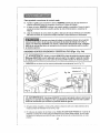
INSTALLING
Straight
Edge
Fig. 13
AND USING THE EDGE GUIDE (Figs. 14 and 14a)
Your saw comes with an edge guide that is 7 1/2-inches long on the guide edge !t allows you
to make accurate parallel cuts when trimming a workpiece It attaches to the saw's base
The arm of the edge guide is stamped 0 to 7 inches in l/B-inch increments and
18 centimeters in l-ram increments for easy adjustment of your cut
1. Unplug the saw
unplug
the saw could ALWAYS
result in accidental
starting
can any
cause
serious personal
Z_ WARNING:
unplug saw
beforewhich
making
adjustments.
Failureinjury.
to
2_
Position the edge guide so the arm with the inch increments is facing "up". Slide
the arm of the edge guide into the mounting slots at the front of the saw's base
(see Fig. 14)
3 Adjust the edge guide to tile desired length of cut
4_ Tighten the edge guide retaining screw
Clamp and support the workpiece securely before making your cut
24
"T
Fig, 14
INSTALLING
AND USING
THE EDGE GUIDE cont.
Place the edge guide firmly
against the edge of the workpiece
(See Fig, 14a) Doing this will
give you a true cut without
pinching the blade
7 BE SURE that the guiding
edge of tile workpiece is straight so
you can get a straight cuL
8 ALWAYS LETTHE BLADE
REACH FULL, SPEED, then
carefully guide the saw into tile
workpiece, DO NOT bind the
blade in the cut Push the
saw forward at a speed
where the blade is not laboring
Fig. 14a
HOWTO
SETYOUR
BEVEL
ANGLE
(Fig. 15)
1. Unplug the saw,
/iX WARNING:
ALWAYS unplug saw before making any adjustments.
Failure to
unplug the saw could result in aceiden'_al starting which can cause serious personal
injury.
2 Loosen bevel adjustment lever (see Fig 15)_
3 Raise the motor housing end of the saw
until you reach the desired angle setting
on the bevel scale
4 Tighten the adjustment lever securely
Polnter
Fig. 15
Bevel Adjustment Lever
MAKING BEVEL CUTS (Figs. 16 and 16a)
t
Line of Cut
45o Indicator
Fig. 16a
Fig. 16
WARNING: ALWAYS clamp and support workpiece securely.. ALWAYS
maintain proper control of saw. Failure to clamp and support workpiece and
loss of control of saw could result in serious injury.
1, Your saw can be adjusled to cut at any angle between 0° and 520 When making 450 bevel
cuts, there is a notch in tile saw base to help you line up timeblade with timeline of cut
(see Fig 16a)
2 Align your line of cut with the left side of the notch by the 450 indicator when making 450
bevel cuts
3 Since blade thicknesses vary and different angles require different settings, MAKE A
TRIAL CUT in scrap material along the guideline to determine how much, if any, you should
offset the blade from the guideline to allow for the kerf of the blade to get an accurate cut.
4. When making a bevel cut HOLD the saw FIRMLY with both hands (see Fig, 16)
5 Rest the front edge of the base on timeworkpiece, then squeeze the trigger switch to start
the saw. ALWAYS let the blade reach full speed, then guide timesaw into the workpiece.
6 After completing your cut, release the trigger switch and allow the blade to come to a
complete stop in the cut. DO NOT remove the saw from the werkpiece while the blade
is moving It will damage your bevel cut and cause Kickback.
reaches full speed, it could cause the saw to kickback towards you, possibly
WARNING:
the blade comes in contact with the workpiece before it
resulting
in serious Ifinjury.
26
7
MAKING
POCKET
/'_ WARNING:
CUTS ( Fig. 17)
ALWAYSadjust bevel setting tozero before makinga pocket
cut. Attempting a pocket cut at any other setting can result in a loss of control of
the saw, which can result in serious injury,
]
J
1 Adjust the bevel setting to zero, set the blade to the correct blade depth setting,
then use the lower blade guard lever to swing the guard up.
/ix WARNING:
serious injury.
ALWAYS raise the lower blade guard with the lever to avoid
.____
--1
Fig. 17
2 While holding the lower blade guard up by the lever, firmly rest the front of the saw base
flat against the workpiece with the rear handle raised so the blade does not touch the
workpiece (see Fig 17).
3 Squeeze the trigger switch to start the saw. ALWAYS let the blade reach full speed, then
slowly lower the blade onto the workpiece until the base is flat against the workpiece
AS the blade enters the material, you MUST release the lower blade guard lever.
4 After you complete the cut, release the trigger switch and allow the blade to come to a
complete stop After the blade has stopped, remove it from the workpiece If the corners
of your pocket cut are not completely cut through, use a hand finishing saw to finish the corners
z_ WARNING:
NEVER tie the lower blade guard in the raised position,
Leaving the blade exposed could result in serious injury.
27
I
I
POSITIVE0° BEVEL STOP
Yoursawhasa positive0° bevelstopanditwasadjustedatthefactorytoassure
0° angleofthesawbladefor900cuts However,
shippingcancausemisalignment
HOWTO
CORRECTTHE
0 ° ANGLE
SE"t-rlNG
(Figs.18,
18a and 18b)
1 Unplug the saw
Z_ WARNING:
ALWAYS unplug saw before making any adjustments. Failure
to unplug the saw could result in accidental starting which can cause serious
personal injury.
Fig. 18
Carpenter'sSquare
Saw Blade
Bevel
}cale
Bevel
Pointer
Bevel Adjustment Locking Lever
2 Place saw in an upside down position on workbench
3. Use a carpenter's square to check the squareness of the saw blade to the base of your saw.
4 If saw is not square, loosen bevel adjustment locking lever (see Fig. 18).
5. Loosen bevel adjust locking nut counterclockwise,
away from bevel adjust bracket, with small wrench
(see Fig 18a).
Use Phillips
screwdriver to
turn bevel adjust
screw up or down
to adjust base
until square with
the blade
(see Fig 18b).
7,
S
When base is square,
tighten nut clockwise
until tight up against
bevel adjust bracket
Tighten bevel
adjustment lever
Fig, 18a
Bevel Adjust Bracket
28
/_
WARNING:
Attempting
lever securely tightened
to make cuts without the bevel adjustment
locking
can result in serious injury.
z_ WARNING:
To ensure safety and reliability, all repairs - with the exception
of the externally accessible brushes - should be performed by a qualified service
technician at a Sears Service Center.
z_ WARNING:
For your safety, ALWAYS turn off switch and unplug circular
saw from the power source before performing any maintenance or cleaning.
It has been found that electric tools are subject to accelerated wear and possible
premature failure when they are used to work on fiber glass boats and sports cars,
wallboard, spackling compounds or plaster.. The chips and grindings from these
materials are highly abrasive to electrical tool parts, such as bearings, brushes,
commutators, etc. Consequently, it is not recommended that this tool be used for
extended work on any fiberglass material, wallboard, spackling compound or
plaster. During any use on these materials, it is extremely important that the
tool is cleaned frequently by blowing with an air jet.
/
during power tool operations, or when blowing dust. If operation Is dusty, also wear
/_
Always wear safety goggles or safety glasses with side shields
a dustWARNING:
mask.
ROUTINE
MAINTENANCE
products, penetrating oils, etc. come in contact with plastic parts, Chemicals can
/_ WARNING:
DO NOT plastic,
at any time
brake
fluids,
gasoline,personal
petroleum-based
damage,
weaken or destroy
whichletmay
result
in serious
injury.
Periodic maintenance allows for long life and trouble-free operation. A cleaning,
lubrication and maintenance schedule should be maintained. As a common
preventive maintenance practice, follow these recommended steps:
1 When work has been completed,
of the tool over time.
clean the tool to allow smooth functioning
2 Use clean damp cloths to wipe the tool.
3 Check the state of all electrical cables.
4 Keep the motor air openings free from oil, grease and sawdust or woodchips,
and store tool in a dry place_
5 Be certain that all moving parts that are exposed are well lubricated, particularly after
lengthy exposure to damp and/or dirty conditions.
29
J
|
LUBRICATION
All of the bearings in this tool are lubricated with a sufficient amount of high-grade
lubricant for the life of the tool under normal operating conditions. Therefore,
no further lubrication is required.
If the blade does not follow a straight
line:
• Teeth are dull, This is caused by hitting a hard object such as a nail, dulling
teeth on one side, The blade tends to cut to the side with the sharpest teeth.
o Base is out of line or bent.
° Blade is bent
• Edge guide or straight edge is not being use&
If the blade binds or smokes from friction:
- Blade is dull.
• Blade is on backwards.
. Blade is bent.
. Workpiece is not properly supported.
- Incorrect blade is being used.
z_ WARNING:
recommended
The use of attachments or accessories that are not
for this tool might be dangerous and could result in serious injury,
Sears and other Craftsman outlets have a large selection of 7 1/4-inch Craftsman
steel carbide-tipped blades designed for specific cutting applications,,
Contractor bulk packs are also available,,
Sears and other Craftsman outlets also offer sawhorses, combination and
framing squares, straight edges, edge guides, and a large assortment of
clamps to help you with all your sawing needs.
Visit your local Sears store or other Craftsman outlets or shop sears corn/craftsman
30
102
NO'_:
lOt_ContaEn_ 30 sg 5_ 57 52 61 _0 fiB_
107 C_ta_ns ?_ 72 _3
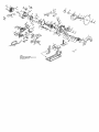
71/4-in.CIRCULARSAW- MODEL NUMBER320.10871
The Model Number will be found on the Narneplate
Always mention the Model Number in all correspondence
Item No,
1
2
3
4,
5
6
7
8
9
10
11
12
13
14
15
16
17
18
19
20
21
22
23
24
25
26
27
28
29
3O
31
32
33
34
35
36
37
38
39
4O
Parts No.
2780040000
3420333000
3420335000
31213390O0
3121340000
3320220000
3320219000
3320221000
3121384000
3121341000
3400174000
5650017000
5640151000
3121378000
3420334000
3121379000
3550225000
3550222000
5620151000
3420184000
2800006000
5610094000
3121051000
3121057000
3121054000
3700255000
5660030000
3550238000
3120560000
3550240000
3660072000
3700539000
5610048000
5620039000
3700262000
5610061000
561004.2000
5610053000
5670008000
5610062000
regarding your tool
Part Description
Laser Set
Gear Case
Upper Guard
Motor Housing
Rear Cover
Right Handle
Left Handle
Front Handle
Lens
Fan Baffle
Lock Rod
Plain Washer GB96-85 6 A140
Bolt
Depth Adjusting Lever
Moving Guard
Moving Guard Lever
Inner Flange
Clamp
Flange Screw
Adjusting Block
Brush Holder
Tapping Screw GB6560-86 4X16
Stopper
Rubber Ring
Spring
Washer
Circlips For Shaft
Lock Shaft
Button
Lock Ring
Spring
Epoxy Board
Tapping Screw GB845-85 4.2X55-F
Screw GB818-85 M4xl0
Wire Holder
Thread Forming Screw GB6560-66 5°i3
Tapping Screw G8845-85 ST4.2x19-F-H
Tapping Screw GB645-65 4.2x9.5-F
Spring Pin GB879-86 6x40
ThreadForming
Screw GB6560-86M5°14
32
Qty.
1
1
1
1
1
1
1
1
1
1
1
1
1
1
1
!
1
1
1
!
2
3
1
1
1
1
1
1
1
1
1
2
2
4
1
1
12
3
1
3
-F
71/4-in.CIRCULARSAW - MODEL NUMBER 320.10871
The Model Number will be found on the Nameplate
Always mention the Model Number in all correspondence
Item No.
41
42
43
44
45
46
47
48
49
5O
51
52
53
54
55
56
57
58
59
6O
6!
62
63
64
65
66
67
68
69
7O
71
72
73
74
76
77
78
79
8O
Parts No.
5610057000
5700041000
57O0O15OOO
3700780000
5680009000
5620044000
3660071000
3700278000
5630001000
3120562000
3700663000
3700865000
5650053000
3400011000
3700280000
5660010000
3550239000
5680004000
3550235000
5700019000
3700281000
5660023000
3121475000
3121424000
3700586000
3810073000
3121381000
3420311000
3121380000
3121382000
3121383OOO
2750160000
2821947OOO
5700013000
4360221000
2821992000
2740066000
2821992000
5650007000
regarding your tool
Part Description
Thread Forming Screw
Oil Impreging Bearing
Ball Bearing GB/T276-94 6201-2RD
Depth Bracket
Rivet GB873-86 6x8
Screw GB818-85 M4X25
Spring
Base Plate
Nut GB6170-86
Line Guide
Fence
Wrench
Washer
M4
Wing Bolt
Support Plate
E Ring GB896-86 9
Gear Shaft
Plain Key GB1096-79
Gear
5x14
Bali Bearing GB_T276-94 6003-2RS
Wave Washer
Circlips For Hole GB893.1_86 35
Power Indieto[ cover (Left)
Power Indictor cover (Right)
Lining
Blade
LED Cover
Gear Case Cover
Angle Lever
LED Support1
LED Support2
Rotor
Transform Assy
Ball Bearing GB T276-94
LED
Inner wire 1
Starer
Inner wire 2
6000-2Z
Spring Washer GB93-87 4
33
Qty.
2
1
1
1
2
1
1
1
1
1
1
1
1
1
1
1
1
1
1
1
1
1
1
1
1
1
1
1
1
1
1
1
1
1
1
1
3
71/4-in.CIRCULARSAW - MODEL NUMBER 320.10871
The Model Number will be found on the Nameplate,
Always mention the Model Number in al! correspondence
item No,
81
82
Parts No
Part Description
regarding your tool
Qty.
4870036000
Switch
1
83
84
85
86
87
88
89
4810002000
3700367000
5610093000
3121050000
Power Cord & Plug
Cord Anchorage
Tapping Screw JIS M4°i 1
Cord Guard
1
1
2
1
3121385000
4930012000
Laser Button
Terminal
1
3
90
91
92
5610059000
5650013000
5650001000
ThreadFarmingScrew G66560-86M5°x2
Plain Washer G897.1-85 5
Plain Washer GB97.1-85 3
1
1
2
93
94
95
5650003000
5620006000
5650005000
Spring Washer GB93-87 3
HexagonSocketScrew G870-85 M3_xl
Plain Washer GB97.1-85 4
2
2
2
96
97
5610058000
3550375000
Tapping Screw G86560-86
Nut M6X2P
1
1
98
99
100
4930013000
5620035000
Receptacle
Screw GB818-85 M3,5°x 8
3
4
101
102
103
104
105
106
107
3660138000
4960021000
5640152000
Torsion Spring
Carbon
Bolt
1
2
1
Base Plate Set
Gear Set
Rotor Set
1
1
1
M5X16
SEE BACK PAGE FOR PARTS ORDERING INSTRUCTIONS
34
I
I
I
I
I
V4pumgadas
Modelo No.
320. 10871
®
Doble Aislamiento
• GARANT{A
o SEGURIDAD
z_ PRECAUCION:
Lea entienda y siga
todas las Normas de Seguridad e Instrucciones
de Funcionamiento en este Manual antes de
usar este producto.
Sears, Roebuck
and Co.,
Hoffman
Estates,
IL 60179
U.S.A.
Visite nuestra p_gina Web Craftsman®:
o DESEMPACADO
o ENSAMBLAJE
o DESCRIPCION
• FUNCIONAMIENTO
o AJUSTES
• MANTENIrtilIENTO
www.craftsman.com
Garantfa....................................................................................
P_glna 36
Sfmbolosde Seguridad .........................................................
P_glna 37
Instruccionesde Seguridad................................................ PAglnas 38 - 45
Glosario de T6rmines..............................................................
P&glnas 45 - 46
Desempacado.........................................................................
PAglnas 46 - 47
Ensarnblaje.......................................................................................
P&glnas 47 - 48
Descripci6n.........................................................................
P_glnas 49 - 51
Funcionamiento...................................................................
PAgJnas 51 - 61
Ajustes..................................................................................
P_glnas 62 - 63
Mantenimiento.............................................................................
P>nas 63 - 64
Detecci6ny Resoluci6nde Problemas...................................
P&glna 64
Accesorios..................................................................................
P#,glna 64
Piezasde Repuesto...................................................................
P_,glnas 65 - 68
NOmerosde Tel_fonodel Serviciode
Piezas
de Repuesto
de Sears ................................................
C0ntratapa
GARANTiA DE UN AI_IO COMPLETO SOBRE PRODUCTOS CRAFTSMAN e
Si este producto Craftsman falla debido a defectos en el material o
mane de obra entre un a5o desde la fecha de cornpra,REGRESELO
A LATIENDA
SEARS O CENTRO DE PARTESY PIEZAS DE
REPUESTOS
U OTRO PUNTO DEVENTA CRAFTSMAN
MAS.
CERCANO EN LOS ESTADOS UNIDOS PARA SU REPARAClON
GRATUITA (O REEMPLAZO
SI LA REPARAClON
RESULTASE
IMPOSlBLE).
Esta garantfa no incluye piezas desechables, tales come Ib,mparas,
pilas, brocas o cuchillas.
Si esta herramienta Craftsman se utiliza para fines comerciales
o de alquiler, esta garantia aplica s61o para 90 dias desde la fecha
de compra.
Esta garant[a le otorga derechos legales especfficos, y es posible que
tambi_n cuente con otros derechos, los cuales varian de un estade
a otro.
Sears,
Roebuck and Co,., Hoffman
iGUARDE
iLEATODAS
ESTAS
INSTRUCCIONES!
LAS INSTRUCCIONES!
36
Estates,
IL 60179
El prop6sito de los s[mbolos de seguridad es Ilamar su atenci6n a posibles peligros
Los simbo!os de seguridad y las explicaciones que los acompa5an, merecen su
cuidadosa
atenci6n y entendimiento.
Las advertencias mediante s[mbolo p0r si
solas NO eliminan el peligro Las instrucciones y advertencias que ofrecen no
sustituyen las medidas de prevenci6n de accidentes apropiadas
Z_ ADVERTENClA:
ASEGURESE de leer y entender todas las instrucciones
de seguridad en este manual, ineluyendo todos los simbolos de alerta de seguridad
tales como "PELIGRO', "ADVERTENClA" y "PRECAUClON',
ANTES de usar esta
sierra. El incumplimiento an seguir todas las instrucciones indicadas a continuaci6n
podr[a resultar en descargas al_ctricas, incendio y/o lesiones personales graves.
DEFINICION
//_
DE LOS SiMBOLOS
ADVERTENClA
SilVlBOLO
DEo PRECAUClONo
ALERTA
DE Puede
SEGURIDAD:
ser utilizado Indica
en conjunto
PELIGRO,
con
otros s[mbolos o pictograma.
.......
"
_
=
"= No obedecer esta adverteneia de seguridad RESULTAR,_ en
muerte o lesi6n grave a usted o terceroso Siga siempre las
precaueiones de seguridad para reducir, el riesgo de incendio,
descargas el6ctricas y lesiones personales.
No obedecer
[--_'ADVERTENCIA:
esta advertencia
de seguridad
PUEDE
I resultar en muerte o lesiones graves a usted o terceros.
Siga siempre las precauciones de seguridad para reducir
el riesgo de incendio, descargas el6ctricas y lesiones
personaleso
•
I/ik
PRECAUCiON,j
.] No obedecer esta advertencia de seguridad PODR{A
resultar en lesiones personales a usted o terceros. Siga
slempre las precauciones de seguridad para reducir el
riesgo de incendio, descargas el6ctricas y lesiones
personaleso
PREVENCIC}N DE DAI/OS Y MENSAJES INFORMATIVOS
Estos informan al usuario sobre informaci6n y/o instrucciones importantes que podr{an conllevar
a da5os al equipo u otra propiedad si no se siguen Cada mensaje es precedido pot la palabra
"NOTA:" como se muestra en el ejemplo a continuaci6n:
NOTA: St estas instrucciones
y/o a la propiedad.
USE SUS
I
I
no se siguen podr[a resultar en daSos al equipo
z_ ADVERTENClA:
El funclonamiento de cualquier
herramienta con una hoja circular pedrian resultar en objetos
for_neos arrojados en sus ojos, Io cual podrlan resultar en
daSos graves a los ojos, Antes de comenzar a usar herramientas
el6ctricas, SIEMPRE use gafas de seguridad con protectores
laterales y protecteres de cara completa cuando sea necesario.
Nosotros recemendamos una M_scara de Seguridad de VisiSn
Amplia para usar sabre gafas de seguridad est_ndar con
protectores laterales, ta cual est& dispenible en las Tiendas
Sears u etros Puntos de Venta Craftsman,
37
1
z_ADVERTENClA:
ASEGURESE de leer y entender todas tas instrucciones
en este manual antes de usar esta sierra circular. No seguir tedas tss instrucciones
podr[a resultar en exposici6n a radiaciones peligrosas, descargas el_ctricas,
incendio y/o lesiones personalss graves,
/
PRECAUClONES
DE SEGURIDAD
PARA EL use DE L.,_SER
Esta sierra circular cuenta con un rayo !_ser integrade El I_ser es de Clase Ilia y emits
una salida de energia de m&ximo 1roW y 635-665nm longitudes de enda Estes I&seres
nermalmente no presentan un riesgo 5price Sin embargo, NO mire el rayo fijamente ya
que este pedria ocasionar deslumbramiento per r_.fagas de luz.
La siguiente etiqueta est& presente en su
herramienta. La misma i ndica d6nde la sierra
emite el rayo I_ser. ESTE CONClENTE de la
ubicaci6n del rayo l_ser al usar la herramienta,
ASEGURESE SIEMPRE que rode tercero que
se encuentre en proximidad de use est_
conciente de los pellgros de mirar
directamente al laser.
RADJACI_N
•
L_SER
NO
bIiRE
FUAMENTE
EL RAYO
635-G_Snnt Pol_cb: < 2,5row Esle ptod_docon _er _bse IP*_
¢11m
pie con I_ nornln2ZCFR, p,lrf_s 1040 J.O y 1040 !]l
Evite qu_ se emita radinci6n del I_ser de
exposici_n
a travbs de esle aperlura_
Z_ ADVERTENClA:
RAYO L,_SER. RADIAClON L,&SER. Evite la ExposiciSn
Directa de los Ojos, NO mire fijamente al rayo. Encienda el rayo Idser s61o
cuando la sierra se encuentre sobre la pieza de trabajo. Ldser Class Ilia.
Z_ ADVERTENClA:
El use de controles, ajustes o la realizaci6n de
procedimientos
distintos a los especificados en este manual podrfa resultar en
exposici6n a radiaci6n peligrosa.
Z_ADVERTENClA:
telescopies
El use de instrumentos 6prices tales come, entre otros,
o trasvases pars ver el rays I&ser incrementard los riesges a los ejos,
1o NO retire ni altere las etiquetas del producto. Retirar las etiquetas del
producto incrementa el riesgo de e×posici6n a radiaci6n I_ser.
2 El rayo Idser puede ser daSino para los ojos. Evite SIEIVIPRE la exposici6n
directa a los ojos_ NO mire directamente a la apertura de salida del rayo I_ser
durante el funcionamiento. NO proyecte el rayo I_ser directamente en los ojos de
terceros. Encienda el I&ser SOLAMENTE al realizar los cortes.
3, Se incluyen gafas pars distinguir mejor el rayo I_,ser en condiciones
NO use las gafas si interfieren con el use seguro de esta sierra,
de luz brillante.
4. El I_,ser en sierras circulares no es un juguete. Mant6ngalo SlEMPRE lejos del
alcance de los niSos, El rayo I_ser emitido per este dispositivo NUNCA DEBE
dirigirse hacia las personas per motive alguno.
5. ASEGORSE que el rayo Idser est6 apuntado hacia la pieza de trabajo (tal come
madera o superficies asperas) sin superficies reflectantes,,
6. NO use sobre rnateriales tales come Idminas de acero con superficies brillantes y
reflectantes. Una superficie brillante podrfa retie ar el rayo de nuevo al operador.
Aseg_rese de que e/rayo I_.ser no se refleje en espejos u otras superf c es
reflectantes, ya que tambi6n pudiera ser peligroso,,
38
k
-T
7. Apague SIEIV1PRE el rayo laser cuando no est6 en uso_ Dejar la herramienta sin
supervisiSn tambi6n puede incrementar el riesgo de que otra persona
inadvertidamente mire directamente al rayo I&ser.
PRECAUClON: Siga SIEMPRE s61o las instrucciones contenidas en este
manual cuando use el I&ser, El uso de esta caracteristlca de cualquier manera
distinta a Io que se indica en este manual podria resultar en exposici6n a radiaci6n
peligrosa.osure.
8. NO intente modificar el desempefio de este dispositivo I&ser de cualquier forma.
Esto podr[a resultar en una exposiciSn peligrosa a la radiaci6n lAser.
9. Use SlEMPRE sSIo accesorios recomendados por Sears para usar con este
producto. El uso de accesorios que han sido diseSados para su uso con otras
herramientas I&ser podr[a resultar en lesiones graves.,
10, Para mAs informaciSn acerca de los I&ser, refi_rase a ANSI-Z136.1 para el
ESTANDAR PARA USO SEGURO DE LASER, disponible del Instituto LAser de
Am6rica (407) 380-1553_
SEGURIDAD
EN EL AREA
DE TRABAJO
1. Mantenga su _rea de trabajo limpia y bien iluminada.
atestados y las Areas oscuras atraen accidentes_
Los bancos de trabajo
2. NO use herramientas
el_ctricas en ambientes explosivos, tales como en
presencia de liquidos, gases o polvos inflamables.
Las herramientas el6ctricas
producen chispas que podrian encender el polvo o gases..
3. Mantenga a observadores,
niSos y visitantes lejos mientras use una
herramienta el_ctrica. Las distracciones podrian ocasionar que pierda el control.
4,. Mantenga su talle de trabajo a prueba de niSos usando candados e interruptores
maestros,, Guarde bajo llave las herramientas cuando no las est6 usandoo
5. ASEGORESE que el Area de trabajo cuente con luz suficiente para que pueda
ver el trabajo y que no existen obstrucciones que interferirAn con el uso seguro
ANTES de usar su sierra_
SEGURIDAD
PERSONAL
1. CONOZCA su herramienta. Lea el manual del operador cuidadosamente. Aprenda
las aplicaciones y limitaciones de la sierra, asi como los peligros potenciales
especificos relacionados con esta herramienta.
2, MANTleNGASE ALERTA, mire Io que est& hacienda y use sentido comun al usar
una herramienta el_ctrica,
3. NO use la herramienta siestA cansado o bajo la influencia de drogas, alcohol
o medicamentos. Un momento de falta de atenciSn mientras usa herramientas
el_ctricas podr[a resultar en lesiones personales graves.
4. VISTA apropiadamente.
No use ropa suelta o joyas. Amarre el cabello largo hacia
atrAs. Mantenga su cabello, ropa y guantes lejos de piezas mSviles. La ropa suelta
o el cabello largo podr[an quedar atrapados en las piezas mSvileso Las aperturas de
ventilaciSn cubren la mayoda de piezas mSviles y deben evitarse.
5. EVITE la encendida de manera accidental Asegurese de que el interruptor est6
en la posici6n "OFF" ("APAGADO") antes de enchufar la herramientao NO sostenga
herramientas con su dedo en el interruptor. Llevar herramientas con su dedo en el
interruptor o enchufar las herramientas con el interruptor en la posici6n "ON"
("ENCENDIDO") atrae accidentes
39
SEGURIDAD
PERSONAL
cont.
6o RETIRE las Ilaves de ajuste o Ilave de la hoja antes de encender la herramientao
Una Ilave dejada en la parte rotativa de la herramienta podria resultar en lesiones
personales.
7 No se extienda para alcanzar. Mantenga una posici6n firme y balanceada en
todo momento. Una posiciSn firme y balanceada permite un mejor control de la
herramienta en situaciones inesperadas.
8. ASEGURE SIEMPRE SU TRABAJO. Use abrazaderas o un tornilto de banco para
sostener el trabajo cuando sea pr&cticoo Es m&s seguro que usar sus manos y libera
ambas manos para manejar la herramienta
9. USE EQUIPO DE SEGURIDAD. Siempre use protecciSn para los ojos. Las
m&scaras antipolvo, zapatos de seguridad antiresbalantes, cascos o protecciSn
para los ofdos debe usarse en condiciones apropiadas.
10. NO USE LA HERRANIIENTA SOBRE UNA ESCALERA o soporte inestable. Una
posiciSn firme y estable sobre una superficie sSlida permite un mejor control de la
herramienta en situaciones inesperadas_
SEGURIDAD
EN EL USO Y CUIDADO DE LA HERRAiVIIEN'TA
,/_ ADVERTENCIA:
ASEGURESE de leer y entender todas las
instruccionee
antes de usar esta sierra. No seguir todas las instrucciones
indicadas a continuaciSn podrfa resultar en descargas el_ctricas, incendio
leeiones personales graves.
y/o
t. SIEIVtPRE use abrazaderas u otras maneras practicas de asegurar y soportar la
pieza de trabajo sobre una plataforma estable. Sostener el trabajo con las manos
o contra su cuerpo es inestable y podria resultar en p6rdida de control,
2_ NO fuerce la herrarnienta° Use la herramienta y hoja correcta para su aplicaci6n.
La herramienta y hoja correcta lograr&n el trabajo mejor y de manera m&s segura a
la velocidad para Io cual fueron diseSadas.
3. NO use la herramienta
si el interruptor
no la enciende o apaga. Cualquier
herrarnienta que no puede ser controlada mediante el interruptor es peligrosa
y debe ser reparada
4o DESCONECTE el enchufe de la fuente de alimentacibn
antes de hacer
cualquier ajuste, cambiar accesorios o guardar la herramienta.
Tales medidas
preventivas de seguridad reducen el riesgo de que ta herramienta se encienda
accidentalmente
5. NUNCA deje la herramienta en funcionamiento.
Ap_guela SIEMPRE, NO deje
la herramienta sin supervisiSn hasta que se haya detenido por completo.
6. ALIVIACENE las herramientas
sin uso fuera del alcance de los nii_os y otras
personas no capacitadas
para ello. Las herramientas son peligrosas en manos
de usuarios no capacitados
7. Presente MANTENINIIENTO alas herramientas
con cuidado. Mantenga las
herramientas
de corte afiladas y limpias. Las herramientas que reciben el
mantenimiento apropiado con laterales de corte afilados evitar&n atascarse
y ser&n m&s f&ciles de controlar.
8. VERIFIQUE si existe una mala alineaci6n o atascamiento
de piezas mbviles,
rotura de piezas y cualquier otra condiciSn que podria afectar el funcionamiento
de la herramienta Si existen daSos, haga que la herramienta sea reparada antes
de usarla, Muchos accidentes son ocasionados pot herramientas real mantenidas
40
"T
SEGURIDAD
EN EL USOY
CUIDADO
DE LA HERRAMIENTA
cont.
9. USE SOLO accesorios recomendados para esta herramienta. Los accesorios que
podrian ser aptos para una herramienta podrfan tornarse peligrosos cuando se usan
con otra herramienta.
SEGURIDAD
ELI_CTRICA
/_, ADVE RTENClA: No permita que los dedos toquen los terminales
enchufe al instalar o retirar el enchufe de la toma.
1. Las herramientas con doble aislamiento est_n
equipadas con un enchufe polarizado (una hoja
mrs ancha que la otra). Este enchufe se ajustar_
a una toma polarizada en un solo sentido. Si el
enchufe no entra por completo en la toma, revierta
el enchufe. Si ann no entra, contacte a un electricista
calificado para que instale una toma polarizada.
No cambie et enchufe en ning_n modo.
2,
de un
Tapade
cala de
®
conectado a
tomacorrlente_-_-lierra
El doble aislamiento [] elimina la necesidad de
cordones de alimentaci6n de tres alambres para
conexi6n a tierra y sistemas de alimentaci6n con
conexi6n a tierra. Aplica s61o para herramientas
Clase It (con doble aislamiento). Esta sierra circular
es una herramienta con doble aislamiento.
Z_ ADVERTENCIA:
El doble aislamiento NO reemplaza la implementaci6n
de normales precauciones de seguridad al usar esta herramienta.
3. ANTES de enchufar la herramienta, ASEGURESE que el vollaje de la toma provisto se
encuentra dentro del rango de voltaje marcado en la placa de datos de la herramienta.
NO use herramientas con clasificaci6n "AC solamente" con fuentes de alimentaci6n DC.
4. EVITE el contacto corporal con superficies con conexi6n a tierra, tales como tuberfas,
radiadores, estufas y refrigeradoreSo Existe un mayor riesgo de descargas el_ctricas si
su cuerpo hace contacto a tierra_
5. NO expenga las herramientas el_ctricas a la Iluvia ni a condieiones de humedad
ni use herramientas el6ctricas en lugares mojados o h_medos. El agua que
penetra en la herramienta el_ctrica incrementar_ el riesgo de descargas el_ctricas.
6. INSPECCIONE el cord6n de la herramienta para verificar la preseneia de da_os.
Entregue cordones de herramientas dafiados al Centro de Servicio Sears.
ASEGURESE de estar constantemente conciente de la ubicaci6n del cord6n
y mant_ngalo lejos de la hoja en movimiento.
7. NO abuse el cord6n. NUNCA use el cord6n para transportar la herramienta ni para
halar el enchufe de la toma. Mantenga el cord6n lejos del calor, aceite, bordes filosos
o piezas m6viles. Remplace todo cord6n daSado de inmediato. Los cordones daSados
incrementan el riesgo de descargae el_ctflcas.
41
NORMAS
DE SEGURIDAD
PARA SIERRAS CIRCULARES
"t
F_
Mantenga las manos lejos de los bordes cortantes y la hoja.
I "Mantenga su segunda mano en el mango auxiliar o cubierta del motor. Si arnbas
manos es_n sosteniendo
[ Z PRECAUCI6N:
la sierra, la hoja no podr_ cortarlas.
Lahojadeceleran
unavezapagadalasierra.
/
/
]
! MANTENGA su cuerpo posicionado a cualquiera de los lados de la hoja de la sierra
y no en linea directa con la hoja. El rebote podria ocasionar que la sierra salte hacia
atrb.s (Ver "Rebote Qu_ Io Ocasiona y Maneras para Prevenirlo" en las p&ginas 18 y 19)
2 NO se extienda para alcanzar debajo det trabajoo El protector no le proteger& de la hoja
debajo de la pieza de trabajo
1
AI aserrar la pieza de trabajo, el protector
inferior de la hoja NO
cubre la hoja del lado inferior de la pieza de trabajo (PKg. 17 Fig. 4). Mantenga
SIEMPRE sus manos y dedos lejos del area de corte°
l
3 VERIFIQUE que el protector inferior se cierra adecuadamente ANTES de cada uso. NO
use la sierra si el protector inferior no se mueve libremente y no cierra Instant_neamente.
Nunca sujete ni amarre el protector inferior en posici6n abierta. Si la sierra es dsjada
caer accidentafmente, e! protector inferior podfia doblarse. Levante el protector inferior
usando fa palanca retrb,ctil El protector funciona apropiadamente si se mueve libremente,
no toca la hoja ni ninguna otra parte en cualquier _.ngulo y profundidad de corte y si
prontamente regresa ala posici6n de cierre
4 VERIFIQUE el funcionamiento
y condici6n del resorte de protector inferior. Si el
protector y resorte no funcionan apropiadamente, DEBEN ser reparados antes del
uso. E! protector inferior de la hoja podria funcionar lentamente, debido a piezas daSadas,
dep6sitos gomosos o acumulaci6n de detritos. NO opera su sierra haste que se haya
reparado o reemplazado el daSo.
5. El protector inferior debe retraerse manualmente SOLO para hacer cortes especiales,
tales como cortes de bolsillo o compuestos, Levante SIEMPRE el protector inferior
utilizando la palanca retr_ctit correspondiente.
En cuanto la hoja penetre el material,
el protector inferior DEBE ser liberado. Pare toda otto corte, el protector inferior debe
funcionar autom_ticamente.
6 AsegLirese SIEMPRE que el protector inferior est_ cubriendo la hoja ANTES de colocar
la sierra sobre un banco de trabajo o en el suelo. Una hoja m6vi! sin protecci6n
ocasionar_ que la sierra se desplace hacia arras, cortando Io que encuentre en su camino
Preste atenci6n a cu&nto tiempo te toma a la hoja dejar de girar despu6s de que se libere
el interruptor
7. NUNCA sostenga en sus manos la pieza que se est& cortando ni en sus piernas.
Es importante soportar la pieza de trabajo apropiadamente para minimizar la exposici6n
del cuerpo, el atascamiento de la hoja o la p_rdida de control
8. SOSTENGA LA HERRAMIENTA por los mangos aislados al realizer operaciones d6nde
la herramienta de corte pueda entrar en contacto con cables escondidos o con su
propio cord6n. El contacto con un cable "vivo" har_ que las piezas met&licas expuestas
electrocuten a! operador.
9 Sujete SIEMPRE la pieza de trabajo de manera segura pare que no se mueva al realizar
elcorte
43
NORMAS DE SEGURIDAD
PARA SIERRAS ClRCULARES
cont.
10 AI aserrar al hilo, USE SIEMPRE una guia de corte o gufa de corte recto. Esto
mejora la precisi6n det corte y reduce la posibilidad de atascamiento de la hoja_
1! USE SlEMPRE hojas del tamaSo correcto y forma correcta det orificio para el eje
(diamante vs, redondo). Las hojas que no concuerdan con la pieza de montaje de la
sierra girar_n de manera elrAtica y ocasionar_n la p6rdida de control
12, NUNOA use arandelas o pemos de la hoja, daSados o incorrectos. Las arandelas
y pernos de la hoja fueron diseRados especialmente pare su sierra, pare un 6primo
rendimiento y funcionarniento seguro
13 NUNCA corte m_s de una pieza ala vez. NO APILE m_s de una pieza de trabajo
sobre la mesa de trabajo a la vez,
14_ EVITE un funcionarniento
o posicionamiento
de las manes inc6modo d6nde un
resbal6n repentino podr[a ocasionar que su mane se mueva en el camino de la hoja,
15. NUNCA alcance debajo del camino de corte de la hoja.
z ADVERTENClA:
Algunas part[culas de polvo oreadas per lijado, aserrado,
triturado, taladrado y otros trabajos de coestrucci6n realizados con herramientae
el6ctricas contienen quimicos conocidos per ocasionar c_ncer, defectos del
nacimiento u otros daSos reproductivos, Algunos ejemplos de estos quimicos son:
o PIome proveniente de pinturas a base de p!omo.
• Silice cristalina proveniente de ladrillos y cementos y otros productos de mamposterfa.
• Ars_nico y c_omo proveniente de madera tratada quimicamente
Su riesgo de exposiciSn var[a dependiendo de cu&n a menudo realiza este tipo
de trabajo. Para reducir su exposici6n a estos qufmicos:
. Trabaje en un _trea bien ventilada
• Trabaje usando el equipo de seguridad aprobado, tel come mascarillas antipolvo
especialmente diseRadas para fiftrar partfculas microsc6picas.
Evite el contacto prolongado con polvo proveniente del lijado, aserrado, triturado,
taladrado y otras actividades de la construcci6n.
Use ropa protectora y lave las
&reas expuestas con agua y jab6n,
Permitir que el polvo penetre en su boca, ojos o descanse sobre la piel puede promover
la absorci6n de qufmicos da_inos
ADVERTENCIA:
El use de esta herramienta puede generar y/o emitir
polvo, el cual podria oeasionar da6os respiratorios graves y permanentes u otras
lesiones, Use siempre protecci6n respiratoria NIOSH/OSHA aprobada contra la
exposici6n al polvo_ Dirija las particulas lejos de su cara y cuerpoo
NORMAS
ADICIONALES
PARA UN FUNC!ONAMIENTO
SEGURO
No seguir todas las instrucciones
listadas a continuaci6n
podria resultar en
l descargas
Z!XxADVERTENClA:ASEGORESEdeleeryentendertodaslasinstrucciones.
el_ctricas, incendio y/o lesiones personales graves.
1 Conozca su herramienta el6ctricm Lea el manual del operador cuidadosamente.
Aprenda las aplicaciones y limiIaciones, asf come los riesgos potenciales de esta
herramienta Seguir esla norma reducir& el riesgo de descargas el_clricas, incendio y
lesiones graves
2 Use SIEMPRE gafas de seguridad o protectores para los ojos al usar esta sierra.
Las gafas para redes los dias solo cuentan con lentes resistentes al impacto; NO son
gafas de seguridad
44
I
-T
I
1
NORMAS
ADIClONALES
PARA UN FUNClONAIV]IENTO
SEGURO
cont.
3_ PROTEJA eLlS puimones. Use una mascara para la cara o mascarilla antipolvn si la
operaci6n generar_ polvn
4 PROTEJA sus oidns. Usa protecci6n personal para los oidns apropiada durante el use
Bajo ciertas condiciones, el ruido producido per esta herramienta podrfa contribuir a la
p6rdida de audici6n
5, TODOS LOS VlSITANTES Y OBSEVADORES DEBEN usar el mismo equipo de
seguridad usado per el ope_ador de la sierra
6 INSPECCIONE Ins cordones de herramienta peri6dicamente y si est&n dafiadns,
haga que Ins reparen en su Centre de Servicio Sears n Instalaci6n de Servicin
Autorizadao ESTE CONClENTE de la ublcaci6n del cordon°
7. Revise SIEMPRE la herramienta para verificar si existen piezas dafiadas. Antes de
continuar usando ssta herramienta, si un protector u otra plaza sst_n dafiados, debeser
inspeccionada cuidadosamente para determinar si funcionar_, apropiadamente y si
realizar_, la funci6n para la cual fue disefiada. Verifique si existe mala alineaci6n o
atascado de piezas m6viles, rotura de piezas y cualquier otra condici6n que podria
afectar el funcinnamiento de la herramienta Un protectnr u otra pieza dafiada debe
ser reparado apropiadamente o reemplazado en el Centre de Servicio Sears.
8. INSPECClONE y retire tndo clavn de la madera antes de preceder a aserrar.
9 GUARDE ESTAS INSTRUCCIONES. Refi6rase a elias frecuentemente
y uselas
para instruir a los demos sobre el use de esta herramienta. Si alguien toma
prestada ta herramienta, asegSrese que tambi6n tenga acceso a estas instrucciones.
Husillo
El eje sobre el cual la hoja o herramienta de code es montada Tambi6n sele conoce come Eje
Revoluciones Per rvlinutn(RPM)
El nOmero de giros completes de un objeto relative en un minutc
Camino de la hoja de la sierra
El _rea sobre, debajo, detr_,s y frente a la hoja, a medida qua se aplica a fa pieza de trabajo
Esa _rea que se certar_ o se ha codado con la hcja
Triscado
La distancia a la cual el diente de ta hoja de la sierra es doblado hacia fuera desde la cara
de la hoja
Corte a inglete
Una operaciOnde corte hecha con la hoja a un &ngulo diferente de 900 con respecto al tope-guia
Cnrte a inglete combinadn
Un carte a inglete combinado es un corte usando un _ngulo de inglete y un angulo de bisel al
mismo tiempo
Corte cruzado
Una operaci6n de code o de formado en sentido contrario a la veta de la pieza de traba]o
Cnrte biselado
Una operaci6n de ccrte hecha con una hoja a cualquier #,ngulodistinte a 90° de la mesa de inglete
Corte de ranura
Un code sin traspaso que produce una muesca o un canal de lade a lade en la pieza de trabajo
(se requiere una hoja especial)
45
I
I
Chafl&n
Code e'lectuado para eliminar una cuba de un bloque de madera de modo que el extreme
(o parle de _ste) quede a un Angu!o diferente de 900
Corte al file Una operaei6n de corte a Io largo de la Iongitud de la pieza de trabajo
Corte manos libres
Realizar un code sin usar una guia, un calibre de inglete, sujeci6n, abrazadera de trabajo, ni otro
dispositivo apropiado para prevenir que la pieza de trabajo gire o se mueva durante el corte
Aserrado en profundidad
Oualquier operaci6n de corte donde la hoja se extiende por completo a trav_s del espesor
de la pieza de trabajo
Cortes no en profundidad
Cualquier operaci6n de corte d6nde la hoja no se extiende por complete a trav_s del
espesor de la pieza de trabajo, como por ejemplo un code rasurado,
Borde delantero
El extremo de la pieza de trabajo que entra en contacto con ta herramienta primero
Linea de fractura
El material retirado por la hoja en un corte en profundidad o la ranura producida por
la hoja en un code no en profundidad o parcial
Rebote
Un peligro que puede ocurrir cuando la hoja se atasca, lanzando la pieza de trabajo
hacia atr&s hacia el operador
Pieza de trabajo o material
El objeto sobre el cual se estb, realizando la operaci6n de corte Las superficies de la
pieza de trabajo se denominan comi_nmente caras, extremes o bordes
Goma Un residuo pegajoso a base de savia proveniente de productos de madera
Resina Sustancia pegajosa a base de savia que se ha endurecido
ADVERTENCIA:
su sierra NUNCA debe ser conectada a la fuente de
alirnentaci6n euando usted est_i ensamblando
pJezas, hacienda ajustes,
instalando o retirando hojas, limpi&ndola o cuando no est_ en uso. Desconecte
la sierra para prevenir que se encienda accidentalmente,
Io cual ocasionarfa
lesiones personales graves.
1. Junto a su sierra circular se incluye una hoja de code (no ensamblada) empacada per
separado, Tambi_n, una Ilave de hoja, almacenada en la base para ser utilizada al
instalar o cambiar la hoja, una guia lateral y un par de gafas de seguridad para
mejorar la visualizaci6n del rayo laser en condiciones de luz brillante
2. Inspeccione la sierra cuidadosamente para asegurarse de que no ban ocurrido roturas
ni da5os durante el transpode. Si faltase cuatquiera de los items mencionados
(refi6rase a ta LISTA DE PARTES de la pb,gina 13), regrese la sierra a su tienda Sears
o punto de venta Craftsman m&s cercano para que la sierra sea reemplazada
ADVERTENCIA:
si cualquier de las piezas est_n rotas o faltantes, NO
intente enchufar el cordSn de alimentaci6n ni usar la sierra hasta que las piezaa
rotas o faltantes hayan sido reemplazadas. No eumplir con esta instrucci6n
podr[a resultar en posibles lesiones graves.
46
!
I
-r
LISTA
DE PARTES
(Fig. 1)
3. Gufa Lateral
I!t
4. Llave de la Hoja t_ I
(para cambiar _j
la hoja)
5_Galas de
_f'_=,]
segurldad para O' "_-_11
meJoramlentodel I_ser
(para mejerar la visualizaci6n del I&ser)
1. Sierrl
2. HoJa
(Sin ensamblar.
instalada en la sierra)
6. Manual del Operador
INSTALACION
DE LA HOJA (Figs. 2 y 2a)
Cuidadosamente, retire la hoja del empaque, inspecci6nela para asegurarse de que no est,.
agrietada ni da_ada.
1 La sierra no debe estar enchufada a la fuente de alimentaci6n
[
Z_ ADVERTENCIA:
Para prevenir lesiones personales, desconecte SIEMPRE
el enchufe de la fuente de alimentaci6n ANTES de ensamblar piezas, hacer ajustes
o instalar las hojas_
2 Coloque ia sierra sobre un lado sobre una superficie plana
3. Para aflojar la palanca de ajuste de la profundidad de corte, levante la sierra por complete
y apriete la palanca Esto le da mejor acceso al &rea de montaje de la hoja (ver la Fig. 2a)
,
Levante la sierra, sobre su base y sobre una superfioie plana (ver la Fig, 2a).
5. Para aflojar el tornillo de sujeci6n del husillo "A", pulse el bot6n de bloqueo del husillo
(ver la Fig, 2) Coloque la Ilave de la hoja sobre el tornillo de sujeci6n del husillo "A"
Mueva la Ilave hacia delante y hacia atr&s hasta que sienta que el bot6n de bloqueo del
husilfo se hunde aOn m_.s y bloquea la hoja en posici6n de manera tal que el tornillo de
sujeci6n del eje pueda ser retirado Manteniendo el bot6n de bloqueo del husillo
firmemente hundido, gire e! tornillo del husillo en sentido ---T-.,u.
".. ', _-----.-, _--k \ I
contrario alas manecillas del reloj para poder retirarlo
Bot6n de _bloqueo del husillo
Palanca de ajuste
de carte en
profundidad _
"D" Externa
Tornillo de Sujeci6n
del husillo "A"
47
la hoJa apuntan hacla arrtba
adelante
INSTALACION
DE LA HOJA
cont. (Figs.
2 y 2a)
ADVERTENCIA:
ASEGORESE de usar guantes de trabajo de protecciSn
mientras manipule la hoja de la sierra. La hoja puede tesionar manos sin protecci6no
ADVERTENClA:
Una hoja de 7 1/4 putgadas es la capacidad m&xima de tas
hojas para su sierra. Una hoja m_s grande que 7 1/4 pulgadas entrar_ en contacto
con los protectores de la hoja. Adem_s, NUNCA use una hoja tan gruesa que
_reviene que la arandela de la hoja exterior se ajuste al lado piano del husillo.
Hojas demasiado grandes o demasiado gruesas podr_an resuttar en un accidente
y ocasionar lesiones graves.
6, Retire por completo el tornillo de sujeci6n del husillo "A" y la arandeia =D" externa
(ver la Fig. 2a).
7. La arandela restante es la arandela para buje que encaja alrededor del eje del husillo
y no requiere set retirada.
8. Coloque una gota de aceite sobre la arandeia para buje interna y sobre ia arandeia
"D" extema donde tocar_,n la hoj&
9 Levante el protector inferior de la hoja usando la palanca del protector de la hoja y
mant6ngalo en posiciSn levantada durante le paso siguiente,
10., Coloque la nueva hoja de sierra en el protector de hoja inferior, sobre el eje del husillo
y contra el buje interno.
NOTA: Los dientes de la hoja deben apuntar hacia arriba en la parte delantera de
la hoja seg_3n se muestra en la (Fig. 2a).
11. Coloque nuevamente la arandeta "D".
12. Mantenga tirmemente pulsado el bot6n de bloqueo del husilto mientras reemplaza el
tomino del husillo y apri6telo a mano en direcci6n de las manecillas del reiojo Luego,
use la Ilave de la hoja para apretar por completo el tornillo de sujeci6n del husilloo
NOTA: NUNCA use una hoja demasiado gruesa como para permitir que la
arandela "D" entre en contacto con el lado piano del husillo.
RETIRO
DE LA HOJA
(Figs.
2 y 2a)
1o Desenchufe la sierra°
2.
Siga los pasos 2 al & de "INSTALACION DE LA HOJA" y retire la hoja (ver la Fig, 2a).
48
]
J
CONOZCA
SU SIERRA CIRCULAR
(Fig. 3)
operacionales
y requerimientos
seguridad.
NOTA: Antes de
intentar usar su de
sierra,
familiaHcese
con todos las caracteHsticas
Su sierra circular cuenta con un motor el_ctrico construido a precisiSn y sSIo debe ser
conectado a una fuente de alimentaci6n de 120 voltios, 60-Hz AC SOLAMENTE (corriente
normal del hogar) NO opere con corriente directa (DC). Esta gran calda en volta!e
ocasionarA p_rdida de potencia y el motor se sobrecalentar&o Si la sierra no funcBona
cuando se enchufa correctamente en una toma de 120 voltios, 60-Hz AC SOLAMENTE.
verifique la fuente de alimentaciSn. Esta sierra cuenta con un cordSn de alimentaciSn de
8 pies, 2 alambres (no requiere adaptador).
La Sierra Circular
ofrece las siguientes
caracteristicas:
1_ Motor de 13 Amp, 5000 RPM (velocidad sin carga). Ofrece fuerza y torque para
cortes rApidos y seguros en madera, madera contrachapada, madera prensada y
materiales a base de madera.
2, LaserTrac TM tLa exclusiva e innovadora
y eficientes!
caracterfstica
para cortes
precisos
3o LUZ DETRABAJO
LED que ilumina el Area de corte para mejor visibilidad_
Esta luz perrnanece encendida cuando la sierra estA enchufada ala fuente de
alimentaciSn
4. Ajustes rApidos para profundidad de corte con una profundidad
maxima
de corte de:
2 3/_ pulgadas a 90;
1 13116 pulgadas de espesor a 45 °
5. Escala para corte en bisel de fAcil lectura se ajusta para una capacidad de
biselado desde 0 ° hasta 52 °
6 Protectores
de la hoja de aluminio
moldeado
para mayor fuerza y durabilidad.
7, Interruptor gatillo de mayor Iongitud para mAximo control y confort. Apri_telo para
encender la sierra y iib_relo para apagarlao
8, Grande base de acero sellado
mayor control de la sierra,
que ofrece una superficie de trabajo estable para un
9. Mango posterior y mango de asistencia delantero,
contorneados y disefiados
ergon6micamente,
de agarre suave para un agarre seguro, control, balance
y conforL
10o Incluye hoja de acero Craftsman ®24 dientes con punta de carburo de tungsteno
para uso general.
11. Bloqueo
12. Incluye
superior
del husillo
de la hoja ensamblada
horde gufa para ayudar a producir certes precisos,
13. Conducto
de eyecci6n
de aserrfn ayuda a dirigir el polvo y astillas lejos del operador.
14. Rodamientos
esf6ricos permanentemente
lubricados
funcionamiento ininterrumpido y de larga duraciSn.
15. Engranajes
maquinados
duraderos
a1100% para un
para una transmisiSn de energ[a eficiente.
49
E
para cambios fAciles de ta hoja.
La Sierra Circular
ofrece las siguientes
caracteristicas
cont.
Inlerruptor del Laser Trac
Apertura del rayo I&ser
Mango posle_
Protector superior
de la hoja
Mango delantero de asistencia
Cubierta del motor
Palanca del protector
inferior de la hoja
3 LED
Escala del bisel
Pelanca de bloqueo
para ajuste del bisel
Uave de la hoja
en la base
Base
retenci6n/sujeciOn
del borde gula
Proteclor inferior
de la hoja
Ranuras de
monta e para
e borde gu a
/
Tornillo de
sujecibn del husillo
ueo del husillo
Mango delantero
... Escala para
code en
de asistencia
L
it_ t/l/l_'_
F,slltl_
\ /
I Lit
profundidad
Palanca del
/ protector
inferiorde
Cubieda del motor --
Palanca de
auste para corte
en profund dad
C
la hoja
i
_"Llavedela
almscena
50
hoja se
en 18 base
Entrada
13 Amps
Clasificaci6n
120V, 60HZ AC
Velocidad sin carga
5000
Di_me_ro de la hoja
71/4 pulgadas
(184 ram)
Profundidad
23/8 pulgadas
(60.33mm)
de corte a 90 °
RPM
Profundidad de corte a 45 °
113/16pulgadas
Angulo m&ximo de biselado
52 °
(46.03
mm)
HOJAS DE SIERRA
Toda hoja de sierra debe mantenerse limpia, afilada y ajustada adecuadamente para que corte
eficientemente El uso de una hoja sin filo pone tensi6n en exceso en ta sierra e incrementa
el peligro de rebo[e Guarde hojas adicionales a la mane. para tenor siempre hojas afiladas
disponibles La goma y pez negra endurecida sobre la hoja frena la sierra. Use removedor
de goma y pez negra, agua caliente o keros_n para retirarlos NO use gasolina
SISTEMA DE PROTECCION DE
LA HOJA (Fig. 4)
El protector inferior de la hoja,
adherido a su sierra circular, est& alli
para su protecci6n, NUNCA debe ser
alterado por cuatquier motivo, Si se
Ilegara a dafiar o comienza a girar
lentamente, NO use so sierra hasta
que el daBo haya sido reparado o
reemplazado. Deje StEMPRE el
protector en su posici6n
correcta de funcionamiento
cuando use la sierra
Fig. 4
Palancadet
aulom&licamente
Cuando se
tea]ice un corte
PRECAUCl0N:
NUNCE use la sierra cuando el protector no est6 funcionando
apropiadamente. El protector debe ser revieado para verificar su funcionamiento
apropiado antes de cada uso. Si la sierra cae al plso, verifique si el protector inferior
y parachoques han sufrido daSos en toda su configuraci6n de profundidad antes de
usar la sierra. NOTA: El protector funciona apropiadamente cuando se mueve libremente
y regresa prontamente a su posici6n cerrada. Si por cualquier motivo su protector de
hoja inferior no se cierra libremente, Ileve la sierra a su Centre de Reparaci6n Sears m_s
cercano antes de usarla.
51
r
REBOTE...QU
Los causas
I_ LO OCASIONAY
COIVIO AYUDAR
A PREVENIRLO
(Fig, 5)
del rebote
\
Profundldad correcta de la hoJa
Fig. 5
_REBOTE
1 E! rebote es una reacci6n repentina debido a
que la hoja de la sierra est,. presionada, se
atasca o est& mal alineada, Io cual ocasiona
que la sierra descontroladamente se levante
y salga de la pieza de trabajo, hacia atrb,s,
hacia el operador
2 Cuando la hoja esl_ presionada o se atasca
debido a qua la linea de fracture se cierra,
la hoja se atasca y la reacci6n del motor empuja
la unidad r&pidamente haeia atr_s, hacia el
operador
3 Sila hoja se tuerce oest& real alineada durante
el corte, los dientes en e! borde posterior de la
hoja pueden hundirse en la parle superior de
la superficie de la madera Esto ocasiona qua
la hoja escale hacia afuera de la linea de fracture
y salte hacia atr&s, hacia el operador.
4 Aserrar en nudes de la madera o cloves en la
plaza de trabajo pueden ocasionar el Rebote.
5 Aserrar en madera mojada o deformada puede
ocasionar el Rebote (ver la Fig 6a)
6 Forzar un corte o no soportar la pieza de trabajo
correetamente puede ocasionar un Rebote
(ver la Fig 6a)
7 El Rebote puede resultar del real use de la
herramienta y/o procedimientos o condicionee
de funoionamiento erradas. Puede evitarse
al tomar los precauciones apropiadas que
se lista a continuaei6n.
52
Fig. 6
Correcto_
La hoJaest_
demasiado en
profundfdad
Maneras para prevenir el Rebote
Libere SIEMPRE el interruptor gatillo si la hoja se atasca o si la
sierra se bloquea. El rebots podria ocasionar que usted pierda el control de la sierra,
resultando en lesiones graves,
1. Mantenga SIEMPRE un agarre firme con
ambas manos en la sierra (vet Ia Fig 7)
y posicione su cuerpo y brazos de manera
tal que le permitan resistir Ias fuerzas del
Rebote Las fuerzas dot Rebo[e pueden
set contreladas pot el operader, si se toman
las precauciones apropiadas
,
Si la Inojase atasca o si interrumpe un corte
por cualquier mofivo, libere StEMPRE el
gatillo y sostenga la sierra sin moverla en
el material hasta que la heja se detenga por
completo NUNCA intente retirar la heja en
movimiento, o podria ocurrir el Rebote.
VERIFIQUE y tome las acciones correctivas
para eliminar la causa de atascamiento de la hoja
Inspeccione la pieza de trabajo para verificar si existe presencia de nudes o claves antes
de cedar Nunca corte un nudo o clavo
4 NO code madera deformada o mojada (ver la Fig. 6a)
5 Soporte SIEMPRE panales grandes para rninimizar el riesgo de que la hoja quede apretada
y Rebote Los paneles grandes tienen la tendeneia a combarse bajo su propio peso
(ver la Fig 6a) DEBE colocar soportes debajo del panel, uno cerca de la linea de corte
y otro cerca del borde el panel (ver la Fig 6)
6 AI reiniciar el corte en la pieza de trabajo, CENTRE la hoja en la linea de fractura
y aseg_rese que los dientes do la sierra no est_n enganchados en el material. Si la hoja
de la sierra se atasca, podria caminar hacia arriba o Rebotar desde la pieza de trabajo
al encender nuevamente la sierra.
7 NO use hojas sin filo o dahadas. Las hojas sin filo, instaladas incorrectamente
o engomadas producen Ifneas de fractura angostas que oeasionan una fricci6n excesiva,
el atasco de la hoja y el Rebete
& MANTENGA la hoja en la configuraci6n de profundidad correcta. La cenfiguraci6n de
profundidad no debe exceder !/4 pulgada debajo del material que se est#, cortando
(vet la Fig. 5). ASEGURESE que la profundidad de la hoja y las palancas de bloqueo
de ajuete est_n apretadas y seguras ANTES de realizar el code Si el ajuste de la hoja
se mueve durante el code, podria ocasionar que la hoja se atasque y Rebote
9 USE PRECAUCION EXTRA al hacer un "Code de Bolsillo" en paredes existentes u etras
Areas ciegas. La hoja que sobresale podria cedar objetos que ocasionen el Rebete
53
_F
HACER
AJUSTES
DE LOS CORTES
EN PROFUNDIDAD
(Fig. 8)
Use SIEMPRE la configuraci6n de plofundidad de hoja co[recta La configuraci6n de
profundidad correcta de la hoja no debe set m_.s de 1/4 pulgada pot debajo del material que
se est_ cortando (ver la Fig,, 5), Permitir una mayor profundidad incrementar_, la posibilidad
de rebote y ocasionar_ que el corte no sea preciso Su sierra est_ equipada con una escala
pare cortes en profundidad que ofrece una mayor precisiSn para la profundidad de code,
La escala para profundidad de co[re est_ ubicada en Ia parte interne posterior de! protector
superior de la hoja.
Fig, 8
Profundidad del Code
Palanca de
pi'ofundidad
de code pare ajustes
PARA CONFIGURAR
LA PROFUNIDAD
DE LA HOJA (Fig. 8a)
1 Desenchufe la sierra
Z_ ADVERTENClA:
SIEMPRE desenchufe le sierra antes de hacer cualquier
ajuste. No desenehufar la sierra podr(a resultar en que se enclenda accidentalmente
y ocasione lesiones personaies graves,
Levante la palanca de ajuste de
la profundidad de code para aflojar
la base (ver la Fig 8)
2_
&_,J'_
\ / P,ofuod ded
IIIII\\del
Code
3 Determine la profundidad de code
deseada
4 Ubique la escala de profundidad de corte
en la parle posterior del protector
superior de la hoja (ver la Fig, 8a),
5 Sostenga la base de la sierra plana
con[re el borde de la pieza de trabajo
y levante o baje la sierra haste que fa
marea det indicador en la abrazadera
quede alineado con la muesca en el
protector de la hoja a la mama de
profundidad de code deseada
,
Apriete la palanca de ajuste de
la profundidad de corte
Escala
pare
_F,g- --II
54
USO DEL RAYO
L.&SER LASER
TRAC_(Fig.
9)
directa de los ojos. NO mire fijamente al rayo, S61o encienda el rayo l_ser cuando la
/_, ADVERTENCIA:
LASER,
sierra
est6 sobre la pieza deRA¥O
trabajo.
L_serRADIACION
Clase Ilia. LASER. Evite la exposici6n
NOTA: Su sierra circular est_ equipada con un rayo I_ser integrado. Para activar
el interruptor del rayo I;_ser, la sierra debe estar enchufada a la fuente de
I alimentaci6n
1, NO encienda el rayo l&ser hasta que
la sierra est{_ sobre la pieza de trabajo
2 Marque la linea de code sebre la pieza
de trabajo
3 Ajuste el _.ngulo de certe y profundidad
de corte segon se requiera
4. Enchufe la sierra y empuje hacia adelante
el interruptar del rayo l&ser para encender
el I#,ser
5 Alinee el rayo I&ser con la linea de carte
(ver la Fig 9)
6 Apriete el interrupter gatillo y lentamente
empuje la sierra hacia adelante usando
ambas manos, Mantenga el rayo I&ser rojo
sobre la linea de code.
7 Apague siempre el rayo I&ser cuando haya
terminado de cortar,
Fig. 9
Z_ PRECAUCION:
Las gafas de seguridad para mejoramiento del I&ser que se
incluyeron mejorar&n la visualizaci6n del rayo I_ser en condiciones de luz brillante.
NO use las gafae ei estas tnterfieren con el funcionamiento
seguro de la sierra
LUZ DETRABAJO
LED
Su sierra circular cuenta con una luz de trabajo integrada para una mejor visibilidad al cortar
Esta luz estA siempre encendida cuando la sierra est#, enchufada a la fuente de alimentaci6n.
55
COMENZAR
A CORTAR
(Fig.
10)
ADVERTENCIA: Sujete y soporte SIEMPRE la pieza de trabajo de manera segura.
Mantenga SIEMPRES control adecuado sobre la sierra. No sujetar y soportar la pieza
de trabajo y la p6rdida de control sobre la sierra podrian resultar en lesiones graves°
1 SIEMPRE use su sierra con las manos posicionadas de manere cor[ecta, con una mane
operando el interruptor gatillo y la otra sobre el mango delantere de asistencia (ver la Fig 10)
z_
ADVERTENClA:
Mantenga SIEMPRE el control apropiado
sobre la sierra pars
asegurar un aserrade m&s seguro y f_ciL La p6rdida de control sobre la sierra podria
ocasionar accidentes que resulten en posibles lesiones graves.
J
2. NUNCA use la sierra con sus
manos posicionadas
como se
muestra en la Fig. 11
Para ayudarle a mantener et control:
3 SIEMPRE soporte la pieza de trabajo
cerca del corte
4. SIEMPRE soporte la pieza de trsbaje
de manera ta! que el certe quede a
su derecha
5 SIEMPRE sujete la pieza de trabaje
pars que no se mueva durante el
corte Coleque la pieza de trabajo
con el lado bueno hacia abajo
41
NOTA: El lado buene de la pieza
de
trabajo es
el
lado del
cLla_
la
apariencia es importante° 1
6 Antes de comenzar a cortar, dibuje una linea
guia a Io largo de la lines de certe deseada,
luego coloque el horde delantero de la base de
la hoja sobre esa parte de la pieza de trabajo
que est6 s61idamente soportada (ver la Fig 10)
7 NUNCA coloque la sierra sobre la parte de la
pieza de trabajo que se caer& al realizar el
corle (ver la Fig 11)
8 SIEMPRE mantenga el cord6n alejado del
_rea de certe. SIEMPRE coloque el cord6n
de manera tal que no cuelgue sobre la pieza
de trabajo cuando est_ realizando el corte
9 Sostenga la sierra firmemente
manos (ver la Fig. 7),
con ambas
Fig. 11
/k
/
ZL&ADVERTENClA:
|
Si el cord6n cuelga sobre la pieza de trabajo durante el
corte, libere de inmediato el interrupter gatfllo. Pars evitar lesiones, desenchufe la
sierra y mueva el cord6n para preventr que cuetgue nuevamente.
Usar la sierra con un cord6n daSado podria resultar en lesianes
graves o muerte° Si el cord6n est& daSado, h&gelo reemplazar antes de usar
nuevamente la sierra.
56
J
Para ayudarle
a mantener
el control
cont.:
10 Apriete el gatillo para encender la sierra. SIEIvlPRE permita que la hoja alcance su
m&xima velocidad antes de comenzar a cortar en la pieza de trabajo
11o AI hacer el corte, SlEMPRE, aplique una presi6n estable y equitativa. Forzar la sierra
producir& cortes imprecisos y podria acortar la vida Otil de la sierra u ocasionar el
Rebote.
12. Una vez finalizado el corte, libere el gatillo y deje que la hoja se detenga por completo
NO retire la sierra de la pieza de trabajo mientras la hoja contin_Je en movimiento.
•
_m
_AIi •
aserrar una pieza de trabajo, el protector inferior de la hoja NO
cubre la parte inferior de la hoja que sobresale de la pieza de trabajo (ver la Fig. 4,
p_gina 17). Mantenga StEMPRE sus manos y dedos lejos del _rea de c0rte, Cualquler
parte de su cuerpo que entre en contacto con la hoja en movimiento podria resoltar
en lesiones graves.
HAClENDO
CORTES CRUZADOS
Y CORTES AL FILO (Figs. 12 y 12a)
1
Z_ ADVERTENCIA:
Sujete y soporte SIEMPRE la pieza de trabajo de manera segura. !
Mantenga SIEMPRES control adecuado sobre la sierra, No sujetar y soportar la pieza
de trabajo y la p_rdida de control sobre la sierra podrian resultar en lesiones graves.
/
1 SIEMPRE use su sierra con las manos posicionadas correctamente (ver la Fig 12)
Linea de corte
i
Fig. 12a
Fig, 12
z_ ADVERTENCIA:
Mantenga SIEMPRE el control apropiado sobre la sierra para
asegurar un aserrado m_s seguro y f_cil. La p6rdida de control sobre la sierra podria
ocasionar accidentes que resulten en posibles lesiones graves,
2 AI hacer cortes cruzados o cortes al filo, alinee Ia Ifnea de corte con el lado derecho de la
muesca al lado del indicador 0 (vet la Fig 12a)
3 En vista que el espesor de las hojas varia, HAGA UN CORTE DE PRUEBA en material de
desecho ale largo de la linea guia para determinar de cu&nto debe separar, si es el caso,
la hoja de la linea guia para permitir que la llnea de fractura de la hoja produzca un corte
preciso.
57
J
HACER
CORTES
AL FILO
SlEMPRE use una guia al hacer cones al filo largos o anchos con su sierra Puede usar un
borde recto o usar la guia de borde qua se incluy6 con su sierra
USO DE UN BORDE
RECTO
(Fig.
13)
Z_ ADVERTENClA"
Sujete y soporte SIEMPRE la pieza de trabajo de
manera segura. Mantenga SIEMPRES control adecuado sobra la sierra. No sujetar
y soportar la pieza de trabajo y la p@rdida de control sobre la sierra podrfan
resultar en lesiones graves.
1_ Puede hacer una guia para corte al filo
eficiente sujetando un borde recto a
su pieza de trabajo.
2. Cuidadosamente, goie la sierra ale
largo del horde recto para obtener un
corte al filo recto (ver la Fig 13)
3 SIEMPRE DEJE QUE LA HOJA
ALCANCE SU MAXIMA VELOCIDAD,
luego cuidadosamente gala la sierra
en la pieza de trabajo NO atasque la
hoja en el corte. Empuje la sierra hacia
adelante a una velocidad a la cual la
hoja no esl_ trabajando en exceso
INSTALACION
Borde
Recto
Fig. 13
Y USO DE LA GUiA DE BORDE
(Figs.
14 y 14a)
Su sierra viene con una guia de borde de 7 1/2pulgadas de Fargoen la gufa de borde, Esta
le permite hacer cortes paralelos precisos a! darle acabado a su pieza de trabajo La misma
se sujeta a ta base de la sierra El brazo de la guia de borde est& estampado de 0 a 7
pulgadas con incrementos de 1/8 de pulgada y !8 centimetros con incrementos de 1 mm
para f6cil ajuste de su corte
1 Desenchufe la sierra
z_
ADVERTENClA"
SIEMPRE desenchufe la sierra antes de hacer cualquier
ajusteo No desenchafar la sierra podria resultar en que esta se enclenda
accidentalmente, Io cual podda ocasionar lesiones personales graves.
2 Posicione la guia de borde de manera tal que el brazo con los incrementos en pulgadas
est6 de cara hacia arriba. Deslice el brazo de la guia de borde en las ranuras de montaje
en la parte delantera de la base de la sierra (ver la Fig, 14),
3 Ajuste la guia de borde a la Iongitud de code deseada
4 Apriete la guia de borde con el tornillo de sujeci6n
5 Sujete y seporte la pieza de trabajo de manera eegura antes de realizar el corte
58
Fig. 14
INSTALACION
Y USO DE LA
GUIA DE BORDE (Figs. 14 y 14a)
cont.
6. Coloque la guia de borde firmaments
centra el borde de la pieza de trabajo
(vet la Fig 14a) Hacer esto le dar_.
un corte verdadero sin apretar la hoja
7 ASEGORESE de que el borde guia
de la pieza de trabajo est_ recta
para obtener un corte
8. PERMITA SIEMPRE QUE LA HOJA
ALCANCE SU M_.XIMA VELOClDAD,
luego cuidadosamente guie la sierra
en la pieza de trabaje. NO atasque
la hoja en el cortm Empuje ]a sierra
hacia adelante a una velecidad a la
cual la hoja no est6 trabajando en
sxceso_
Fig. 14a
COMO
CONFIGURAR
EL ._NGULO
DEL BISEL
(Fig. 15)
1 Desenchufe la sierra
Z_ ADVERTENCIA:
SIEMPRE desenchufe la sierra antes de ha;e_'_-']
a usta, No desenchufar la sierra podr[a resultar en que esta se encienda
accidentalmente, to cual podr a ocas onar esiones personales graves
2.
I
j
Afloje la palanca de ajuste del bisel
(ver la Fig_15).
3 Levante el extremo de ta cubierta
de! motor de la sierra hasta que
alcance e! _ngule deseado en la
escala del biseL
--Punter_
del bisel
4 Apriete la palanca de ajuste del bisel
de manera segura
Fig, 15
59
Palanca de bloqueo para
ajuste det bisel
q-
HACIENDO
CORTES BISELADOS
(Figs. 16 y 16a)
J
Linea de corte --_
i
Figo 16a
ADVERTENCIA:
Sujete y soporte SIEMPRE la pieza de trabajo de manera
segura. Mantenga SIEMPRES control adecuado sobre la sierra. No sujetar y soportar
la pieza de trabajo y ta p6rdida de control sobre la sierra podrian resultar en lesiones
graves.
1
|
1 Su sierra puede ajustarse para cortar a cuafquier &ngule entre 0 ° y 52 o AI hacer cortes
biselados de 45 °, existe una muesca en la base de la sierra para ayudarle a alinear la hoja
con ia flnea de corte (ver la Fig !6a)
2 Alinee su linea de code con el lado izquierdo de la muesca al tado del indicador de 45 o
al hacer cortes de bisel de 45 o
3 En vista que el espescr de las hojas varla, HAGA UN CORTE DE PRUEBA en material
de desecho a to largo de la linea guia para determinar de ctl&nto debe separar, si es el
caso, la hoja de la linea guia para permitir que fa linea de fractura de la hoja produzca
un corte precise
4 AI realizar un corte de bisel SOSTENGA la sierra FIRMEMENTE con ambas manos
(ver la Fig 16)
5 Reesteblezca el borde delantero de la base de la pieza de trabajo, luego apriete el gatillo
para encender la sierra SIEMPRE permita que la hoja alcance su mMima velocidad,
luego gaie la sierra en la pieza de trabajo
6 Una vez completado el code, libere el interruptor gatillo y perrnita que la hcje se detenga
por complot en el corte NO retire la sierra de fa pieza de trabajo mientras la hoja continue
en movimiento DaSaria su code en bisel y podria ocasionar el Rebote.
3
Si la hoja entra en contacto con la pieza de trabajo antes
|
de alcanzar su m_xima velocidad, podria ocasionar que la sierra rebote hacia usterJ,
resultando en posibles !esiones graves.
ADVERTENClA:
6O
i
1
HACIENDO
CORTES
DE BOLSILLO
(Fig. 17)
ADVERTENCIA:
SIEMPRE ajuste la configuraeiSn del bisel en cero
antes de hacer un corte de botsillo. Intentar un corte de bolsillo en cualquier
otra configuraci6n podria resultar en p6rdida de control de la herramienta
y consiguientes lesiones graves,
Ajuste en cero la configuraci6n del bisel, establezca la configuraci6n de profundidad
correcta de la hoja, luego use la palance del protector inferior de la hoja para oscilar
el protector hacia arriba
ADVERTENCIA:
SIEMPRE levante el protector
la palanca para evitar lesiones graves,
inferior de la hoja desde
Mientras sostiene el protector inferior de la hoja hacia arriba desde la palanca, descanse
la parte delantera de la base de la hoja plana contra la pieza de trabajo con e! mango
posterior levantado para que la hoja no toque la pieza de trabajo (vet la Fig 17)
3 Apriete el interruptor gatilio para encender la sierra SIEMPRE permita que la hoja
alcance su mb,xima velocidad, luego ]entamente baje la hoja sobre la pieza de trabajo
hasta que la base est_ plana contra la pieza de trabajo A MEDIDA que la hoja penetra
en el material, usted DEBE liberar la palanca del protector inferior de la hoja.
4 Una vez completado el code, libere el gatillo y permita que la hoja se detenga per completo
Una vez detenida la hoja, retirela de la pieza de trabajo Si las esquinas de su bolsillo no se
han cortado por completo, use una sierra manual para darle el acabado alas esquinas
[
ADVERTENCIA:
NUNCA amarre el protector inferior de la hoja en posici6n
levantada. Dejar la hoja expuesta podrfa resultar en lesiones graves,
61
PARADA
SEGURA
DEL BISEL
A 0°
Su sierra est_ equipada con una parada segura del bisel a 0° el cual fue ajustado en la f_brica
para asegurar un _.ngulo de 0° de la hoja de la sierra para cortes a 900 Sin embargo,
el transporte podda ocasiona_ una p_rdida de alineaci6n
COMO CORREGIR
EL AJUSTE
1. Desenchufe la sierra.
DEL ,_,NGULO
DE 0 ° (Figs.
18, 18a y 18b)
ADVERTENCIA:
SIEMPRE desenchufe la sierra antes de hacer cualquier
ajusta. No desenchufar la sierra podrfa resultar en que esta se encienda accidentalmente,
Io cual podria ocasionar lesiones personales graves
Escuadra de carpintero
Hoja de la sierra
Fig. 18 !
scala
del bisel
del bisel
,_
Puntero
Palanca de bloqueo del ajuste del biset
2 Coloque la sierra en posici6n invertida hacia abajo sobre el banco de trabajo.
3 Use una escuadre de carpintero para verificar si la hoja de la sierra est,. cuadrada en
relaci6n a la base de su sierra.
4 Si la sierra no estb. cuadrada, afloje la palanca de bloqueo del ajuste de! bisel (ver la Fig 18)
5 Aflo e la tuerca de bloqueo de a uste del bisel girAndola en sentido contrario alas manecillas
del re!oj, lejos ce la abrazadera de ajuste del bise, con una
Ilave peque5a (ver la Fig 18a)
6 Use un destornillador Phillips para girar el tornillo de ajuste
del bisel hacia arriba o hacia abajo para ajustar la base
hasta que cuadre
con la hoja
(ver la Fig 18b).
Una vez cuadrada la
base, apriete la
tuerca gir_.ndola en
sentido de las
manecillas de!
reloj hasta qua est_
ajustada contra Ia
abrazadera de ajuste
del bisel.
8 Apriete la palanca
de ajuste det bisel
Abrazadera 3araajuste del bisel
62
/K
ADVERTENCIA:
Intentar hacer cortes sin que la palanca de ajuste del bisel
est_ apretada de manera segura podria resultar en lesiones graves.
Z_ ADVERTENCiA:
Para asegurar seguridad y confiabilidad, toda reparaci6n
debe set realizada pot t_cnicos calificados en un Centro de Servicio Sears.
z_
ADVERTENCIA:
desenchufe la sierra circular
mantenlmiento o limpieza.
Pare su seguridad, apague SIEMPRE el interruptor y
de la fuente de alimentaci6n antes de realizer cualquier
]
Se ha encontrado que las herramientas el_ctricas est&n sujetas a desgaste y fallas
prematuras cuando se utilizan sobre botes de libra de vidrio y autos deportivos, tabtaroca,
compuesto de relleno o yeso Las astillas y residuos de estos materiales son altamente
abrasivos para la piezas de herramientas el_ctricas, tales como rodamlentos, cepillos,
conmutadores, etc. Consecuentemente, no se recomienda que esta herramienta sea
utilizada para trabajos extensos sobre cualquier material de fibra de vidrio, tablaroca,
compuesto de retleno o yeso. Durante cualquier uso sobre estos materiales,
es ex_remadamente importante que la herramienta sea limpiada con frecuencia
usando un propulsor de aire.
1
al operar herramientas el_ctricas, o al soplar polvo. Si la operaci6n es polvorienta,
/K
slempre gafas de seguridad con protectores laterales
use ADVERTENClA:
tambi_n una mascarilla Use
antipolvo.
IV1ATENIMIENTO
J
|
DE RUTINA
1
I
base de petr61eo, aceites penetrantes etc. entren en contacto con las piezas
o
pl_sticas.
Los
qulmicos
pueden
daRar,
debtlitar
o
destruir
el
pl_stico,
Io
cual
podrla
Z_ ADVERTEN ClA: NUNCA deje que fluido de frenos, gasoline, productos a
resultar en lesiones personales graves.
El mantenimiento peri6dico permite una vida tJtil larga y un funcionamiento libre de
problemas. Mantenga un cronograma de limpieza, lubricaciRn y mantenimiento. Como
pr&ctica de mantenimiento preventivo comQn, siga los siguientes pasos recomendados:
1 AI finalizar el trabajo, limpie la herramienta para permitir un funcionamiento
ininterrumpido de la herramienta a io largo del tiempo.
2. Use paros limpios y humedos para limpiar la herramienta.
3. Verifique el estado de todos los cables el_ctricos.
4. Mantenga las aber[uras del motor libres de aceite, grasa y aserdn o astillas y guarde
la herramienta en un lugar seco.
5. Aseg_rese que todas las piezas m6viles est6n bien lubricadas, particularmente
despu@s de una large exposiciRn a condiciones htamedas y/o sucias.
63
|
LUBRICACION
Todas los rodamientos en esta herramienta han sido lubricados con lubricante de alto
grado suficiente para la vida t3til de la herramienta en condiciones normales de operaci6n.
Por Io tanto, no se requiere de ulterior lubricaci6n.
Si la hoja no sigue una Ifnea recta:
• Los dientes est_n sin filo. Esto es producto de golpear objetos duros tales como
clavos, Io cual hace que los dientes pierdan el filo de un lado. La hoja tiende a
cortar del lado con los dientes m&s afilados..
= La base est& fuera de lfnea o doblada.
• La hoja est_ doblada.
=La guia de borde o gu[a recta no se est& usandoo
Si la hoja se atasca o emite humo producto de la fricci6n:
• La hoja no tiene filo.
• La hoja est_ al rev6s
o La hoja estA doblada
• La pieza de trabajo no est_ soportada adecuadamente,
o Se est#, usando una hoja inadecuada.
]
[Z_
para ADVERTENCIA:
esta herramienta podrian
El use
set de
peligrosos
conexiones
y podr_an
o accesorios
resultar noenrecomendados
lesiones graves,
Sears y otros puntos de venta Craftsman cuenta con una amplia selecci6n de hojas
de 7 V4 pulgadas Craftsman de acero con dientes con punta de carburo de tungsteno,
diseRadas para aplicaciones especfficas de corte. Tambi6n existen disponibles
empaques a granel para contratistas.
Sears y otros puntos de venta Craftsman tambi6n ofrecen cabrillas, escuadras de
encofrado y combinadas, bordes rectos, guias de borde y una gran variedad
de abrazaderas para ayudarle con todas sus necesidades de aserrado.
Visite su tienda local Sears u otro punto de venta Craftsman o compre
por Internet en sears.corn/craftsman.
64
J/
/I
/
/
_rr
nmw
G8
1"-
Sierra Circular de 7 1/4pulgadas - MODELO NO. 320.10871
El Nurnero det Modelo se encuentra en la Placa de Identificaci6n Mencione siempre
el NQmero del Modelo en toda correspondencia acerca de su herramienta
No. item
I
2
3
4
5
6
7
8
9
10
11
12
13
14
15
16
17
16
19
20
21
22
23
24
25
26
27
28
29
30
31
32
33
34
35
36
37
38
39
4O
No. Parte
2780040000
3420333000
3420335000
3121339O0O
3121340000
3320220000
3320219000
3320221000
3121384000
3121341000
3400174000
5650017000
5640151000
3121378000
3420334000
3121379000
3550225000
3550222000
5620151000
3420184000
2800006000
5610094000
3121051000
3121057000
3121054000
3700255000
5660030000
3550238000
3120560000
3550240000
3660072000
3700539000
5610048000
5620039000
3700262000
5610061000
561OO42O00
5610053000
5670008000
5610062000
Cant.
Descripci6n
de la Parte
Set del laser
Estuche de engranajes
Protector superior
Cubierta del motor
Cubierta posterior
Mango derecho
Mango izquierdo
Mango delantero
Lente
Deflector del ventilador
Vadlla de bloqueo
Arandela plana GB96-85 6 A140
Tuerca
Palanca de ajuste de profundidad
Protector mTvil
Palanca del protector m6vil
Brida interior
Abrazadera
Tornillo bridado
Bloque de ajuste
Portacepillo
Tomillo roscador GB6560-86 4X16
Tope
Aro de goma
Resorte
Arandela
Arandelas
de retenciOn para el eje
Eje de bloqueo
Bot6n
Anillo de bloqueo
Resorte
Tabla Epoxy
Tornillo roscador GB845-85 4.2X55-F
Tornillo GB818-85 M4X 10
Porta cables
Tornillo roscado
Torni!lo roscador
Tornillo roscador
Perno a resorte
Tornillo roscado
66
GB6560-86
GB845-85
GB845-85
GB879-86
530
ST4.2x19-F-H
4.2x9.5-F
6x40
GB6560-86 M5,o40
1
1
1
1
1
1
1
1
1
1
1
1
1
1
1
1
1
1
1
1
2
3
1
1
1
1
1
1
1
1
1
2
2
4
1
1
12
3
1
3
I
I
I
Sierra Circular de 7 1/4pulgadas - MODELO NO. 320.10871
El Nt]mero del Modelo se encuentra en la Placa de IdentificaciSn Mencione siempre
el Nt3mero del Modelo en toda correspondencia acerca de su herramienta
No. item
41
42
43
44
45
46
47
48
49
50
51
52
53
54
55
56
57
58
59
6O
61
62
63
64
65
66
67
68
69
70
71
72
73
74
75
76
77
78
79
8O
No. Pa_e
5610057OOO
5700041000
5700015000
3700780000
5680009000
5620044000
3660071000
3700278000
5630001000
3120562000
3700663000
3700865000
5650053000
3400011000
3700280000
5660010000
3550239000
5680004000
3550235000
5700019000
3700281000
5660023000
3121475000
3121424000
3700586000
3810073000
3121381000
3420311000
3121380000
3121382000
3121383000
2750160000
2821947000
5700013000
4360221000
2821992OOO
2740066000
2821992000
5650007000
Descripci6n
de la Parte
Tornillo roscado
Rodamiento a aceite
Rodamiento
esf_ric0GB/T276-946201-2RD
Abrazadera para profundidad
Remache GB873-86 6x16
Tornillo roscado GB6561-86 M4xl 2
Resorte
Placa base
Soporte de profundidad
Indicador de _.ngulo
Torni!lo GB818-85 M4_6
Soporte del _.ngulo
Arandela
Tuerca de mariposa
Placa de soporte
Anillo E GB896-86 9
2
1
1
1
2
1
1
1
1
1
Ensamblaje del transformador
Rodamiento
esf_ricoGB_T276-946000-2Z
1
1
1
1
!
1
1
1
1
1
1
1
1
1
1
1
1
1
1
1
1
1
LED
Alambrel inferno
Estator
Alambre2 interno
Arandela de resorte GB93-87 4
1
1
1
1
3
Eje del engranaje
Llave plana GB1096-79 5x14
Engranaje
RodamienIo
esf_ricoGB_T276-946003-2RS
Arandela de presi6n
Arandelade retenci6nparaorificioGB893.1-8635
CubieriadellndicadordeAlimenlaci6n(Izquierda)
CubiertadelIndicadordeAtimentaci6n
(Derecha)
Revestimiento
Hoja
Cubierta del LED
Cubierta del estuche de engranaje
Palanca de Angulo
Soportel del LED
Soporte2 del LED
Rotor
67
I
I
Cant.
Sierra Circular de 7 1/4pulgadas - MODELO NO. 320.10871
El NQmero del Modelo se encuentra en la Placa de identificaci6n Mencione siempre
el Nt]mero del Mode!o en 1oda correspondencia acerca de su herramienta
No. item
81
82
83
84
85
86
87
88
89
9O
91
92
93
94
95
96
97
98
99
100
101
102
103
104
105
106
107
Cant.
No. Parte
Descripci6n
4870036000
4810002000
3700367000
5610093000
3121050000
Interrupter
Cord6n y enchufe de alimentaci6n
Anclaje del co[d6n
Tornilloroscador
JIS M4 12
Protector del cerd6n
1
1
1
2
1
3121385000
4930012000
5610059000
5650013000
5650001000
5650003000
5620006000
5650005000
Bot6n del I_.ser
Terminal
Tornillo roscado GB6560-86
Recept#,cufo
Tornillo GB818-85 M3.58
1
3
1
1
2
2
2
2
1
1
3
4
Resorte de torsi6n
Carb6n
Perno
1
2
1
Set de soporle
Set de engranaje
Set del rotor
1
1
1
5610058000
3550375000
4930013000
5620035000
3660138000
4960021000
5640152000
de la Pa[te
M5_20
Arandela plana GB97.1-85 5
Arandela plana GB97.1-85 3
Arandela de resorte GB93-87 3
Tornillo Allen hexagonal GB70-85 M3_12
Arandela plana GB97.1-85 4
Tornillo roscador GB6560-86 M5X16
Tuerca M6X2P
VER EL ANVERSO PARA INSTRUCClONES
68
SOBRE COMO ORDENAR
PARTES
w_F
I
I
70
J
71
I
I
I
Get it fixed, at your home
Your
For ,eLalr
- in your
home
Home
-of
avm anu garde h equc_rnent
no matter who made
or ours!
all major
brand appliances
or i_ea_ g al,d cecil, g systems.
it. no matter wile sold it]
For the replacement parts accessories and
owner's manuals thai you nee(l :_odo,it,/ourself
For Sears
erofessiona
nsta
aRd Items _ke garage
a,,on or home appliances
uoor openers
1-800-4-?TrY-HOME:'
[email protected]£'3,
WV_V.Se ars,c orrl
and water
heaters
/_n_ime: d_,' or nigb,L
(LI S.A andCanedal
"_iot_tw,_.ear_,.¢a
Our Home
For repair of c_,rr,'-in prodLIcts ike w, cuums
lawn equipment_
and e_ectronics, caI or go en-Iine fo[ the nearest
Sears
1-800-4884
Parts
222
and Repair
Al_ytlme.
Center.
da_' or n_ght _U S A
L
o,'l,'y)
%_O/tYg',r.
_38 _ r S 6art'
t"
To u',_rchasea prolect_en agreement (USA )
or ma_.n.tenanceagreement (Canada) on a prodt,£t seR4Ced by Sears
1-800-827-6655
Para _d;r
_Js A)
se[v=,cb de feparac#n
a domicil_o ypara ord=nar
....
__niezas
1-.882.-SU4"4OGAR,'
t_.-885.78,14427
1-800-361-6665
(Canada)
Au Canada Dnur ser_'_ueen [ran_,as.
1.800-LE-FOYER;"
(1-ve00-53.'_69371
WWt?/sears
e_
,_, Re_:;1_red Tladema rk t :_'_"[ ademm k ! _"__e ',' ce Ma k of Se_.r_ B ands. LL'C
¢i Marca Regi:4rada / TM Ma:ea de F#.brica !"t4 M_a[c_ {Je S_IvicicJ de Sear,.. B_nd_
%_que de cm
_e ce !
_,arque deposee de Sem'_ Brantf_. LLC
I_LC