1
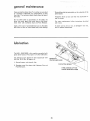
Save This Manual
For Future Reference
MODEL
NO.
113,206801
JOINTER/PLANER
ONLY
113.206931
JOINTER/PLANER
WITH
LEGS AND MOTOR
Serial
Number
Model
and serial
number
may be found
on a plate attached
to your base.
You should
record both
model and serial
number
in a safe place for
future use.
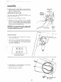
CAUTION:
6 -INCH
Read GENERAL
and ADDITBONAL
SAFETY
• assembly
aNSTRUCTIONS
o operating
carefully
Sold by SEARS,
Part
No. 67037
JO/N TER-PL A NER
• repair parts
ROEBUCK
AND
CO.,
Chicago,
IL
60684
U.S.A.
#,_._._
_bS._
general
safety
instructions
1. KNOW YOUR
POWER TOOL
Read and understand
the owner's
manual and labels
affixed
to
the
tool.
Learn
its application
and
limitations
as well
peculiar to this tool.
2. GROUND
as the
specific
potential
hazards
ALL TOOLS
This tool
is equipped
with
an approved
3-conductor
cord and a 3. arong grounding
type plug to fit the
3roper grounding
tv_ae receptacle.
The green conductor
r_ the cord is the grounding
w_re. Never connect
the
green wire to a I,ve terminal.
3. KEEP GUARDS
_r_ working
alignment.
IN PLACE
order,
and
_n
proper
4. REMOVE ADJUSTING
AND WRENCHES
adjustment
and
KEYS
Cluttered
AREA
areas
must not
and
be sl operv
-6. AVOID
CLEAN
benches
inwte
accidents.
tools
use power
expose
Provide
them
to rain. Keep work
area well
adequate surrounding
work space,
7. KEEP CHILDREN
visitors
should
n damp
or
wet
locations
or
ghted,
AWAY
be kept
a safe distance
from
work
_rea,
8. MAKE WOR KSHOP KID-PROOF
wtth
padlocks,
starter keys.
9. DON'T
master
switches
or
by
removing
job better
Don't
force
designed
11, WEAR
TOOL
or attachment
to do a ]ob
tt was
not
PROPER APPAREL
Do not wear loose clothing,
gloves, neckties or jewelry
(rings, wrist
watches)
to get caught
in moving
parts.
Nonstip
footwear
is recommended.
Wear protective
hair covering
to contain
long hair. Roll tong sleeves
above the elbow.
12. USE SAFETY
GOGGLES
(Head Protection)
Wear Safety goggles (must comply
with ANS Z87.1 ) at
all times.
Everyday
eyeglasses
only
have impact
resistant
lenses, they are NOT safety glasses.
Also, use
face or dust mask if cutting
operation
is dusty, and ear
of
14. DON'T OVERREACH
Keep proper
footing
15. MAINTAIN
and balance
at all times,
TOOLS WITH
<eep
toots
performance.
CARE
shart)
and
clean
Fo[tow
instructions
for
for
Pest and safest
l[_bricating
and
chang_ rig accessories.
before
blades,
TOOLS
servicing;
when
bits, cutters, etc.
changing
!7. AVOI D ACCI DENTAL
Make
in,
sure switch
accessories
such
as
STARTING
Is tn "OFF"
position
before
ACCESSORI
ptuggmg
ES
Consult
the
owner's
manual
for
recommended
accessories.
Foltow
the instructiOnS
that accompany
the accessories.
The use of _mproDer accessories
may
cause hazards.
19. NEVER
STAND
ON TOOL
Serious
injury
cutPng
[ool
Do not
_.[ore materials
Before
will
for.
periods
Use clam3s or a vise to hold work when practical.
It's
safer than using your hand, frees both hands to operate
tool.
could
occur
_saccidentally
if the tool
operate
Check
be carefully
properly
for alignmem
or if the
to reach
such that
them,
PARTS
use of the tool,
should
is t_pped
contacted.
above or near the tool
DAMAGED
further
_s damageo
tool
dt_Hng extended
13. SECURE WORK
20. CHECK
and safer at the rate for which
tt was designed.
10. USE RIGHT
(plugs or muffs)
_t _s_)ecessary to stand on the too
FORCE TOOL
It w_!t do the
fools
18. USE RECOMMENDED
ENVIRONMENT
Don't
AIr
Floor
due to wax o_ sawdust.
DANGEROUS
protectors
operation.
16. DISCONNECT
Form hab, t of checking
to see that keys and adjusting
wrenches
are removed
from tool before turning
lr on
5. KEEP WORK
For power
a guard
and perform
of
moving
or other
checked
part that
to ensure
its intended
parts, binding
that
_t
function.
of moving
parts,
breakage
conditions
that
of parts,
may ,affect
mounting,
and any other
_ts operation.
A guard or
other
is damaged
should
part
that
be 3roperly
repa_reo
or replaced.
21. DIRECTION
Feed work
of rotation
OF FEED
into a blade or cutter against
of the blade or cutter on y
22. NEVER LEAVE
UNATTENDED
Turn
power
complete
off
stop.
TOOL
Don't
the
dtrection
RUNNING
leave
tool
untd
_t comes
to a
Safetyis
alertness
a combination
of operator
common
sense and
at all times when the Jointer*Planer
is being used.
9.
2. GETTING
POWER
BASIC MACHINE
4.
USE OF HOLD-DOWN/PUSH
5. MAINTENANCE
6. STABILITY
OPERATION
FACE,
EARS,
BODY
2
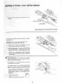
TO KNOW YOUR JOINTER-PLANER
3.
HANDS,
b. Wear safety goggles that comply
with ANSI
Z87,1
and a face shield if operation
is dusty. Wear ear plugs
or muffs during extended periods of operation.
PAGE
FOR
EYES,
If any part of yOur jointer is malfunctioning,
has been
damaged or broken . . . such as the motor switch, or
other operating
control,
a safety device or the power
cord . . . cease operating
immediately
unlit
the
particular
part is properly
repaired or replaced.
WARNING:
FOR YOUR OWN SAFETY, DO NOT ATTEMPT TO OPERATE YOUR JOINTER-PLANER
UNTIL
IT IS COMPLETELY
ASSEMBLED AND INSTALLED
ACCORDING TO THE INSTRUCTIONS .., AND UNTIL
YOU HAVE READ AND UNDERSTOOD THE FOLLOWING.
1. GENERAL
SAFETY
INSTRUCTIONS
TOOLS
..................................
PROTECTION:
...............
BLOCKS
C.
12
t8
.........
19
...........................
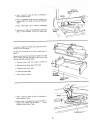
Do not plane, ioint, or bevel wood shorter than !2
in. Smaller
pieces of wood
can tip over on the
tables, or into the cutterhead
and be kicked back toward you,
Always use the hold down/push
block when }ointing
or beveling wood narrower
than 3 in. but never ioint
or bevel wood narrower than 3/4 in,, or less than 1/4
inch thick.
21
OF MACHINE
e.
if there is any tendency
for the Jointer-Planer
to tip
over or move during
certain
operations
such as when
planing
or jointing
long
heavy
boards,
the JointerPlaner (stand) should be bofted to the floor.
Always use the hold down/push
blocks when
wood thinner than 3 in, but never plane wood
than 1/2 in. under any circumstances.
f. Avoid
could
awkward
hand
cause a hand
positions,
to move
planing
thinne_
where a sudden
into the cutters.
slip
7. LOCATION
The Jointer-Planer
should be positioned
operator
nor a casual observer
is forced
with the wood while it is being planed.
This
machine
adequate
8.
is intended
for
indoor
Never turn your Jointer-Ptaner
"ON"
before clearing
the table(s)
of all objects (tools, scraps of wood, etc,)
except for the workpiece
and related feed or support
devices for the operation
planned.
so neither the
to stand in line
use only.
Provide
h,
lighting.
KICKBACKS
Make sure the cutterhead revolves
tion, (toward
the infeed table).
i. KEEP CUTTER
ING PROPERLY
Kickbacks
can cause serious injury.
A kickback
occurs
when the operator
looses control
of the workpiece
causing it to be kicked back toward him.
Kickbacks - and possible
avoided by:
injury
a. Hotdingthe
firmly
workpiece
from
them can usually
against tables
the tension
satisfactory
Jointer-Ptaner
be
c. Not jointing,
planing,
or beveling
pieces of
smaller than recommended.
(See section in this
ual, "BasicJointer-Planer
Operations.")
Smaller
of wood can tip over on th[ tabtes0 or into the
head and can be kicked back toward you.
wood
manpieces
cutter
GUARD
1N PLACE
AT ALL TIMES.
of the cutter
operation.
(See
section.)
right
direc-
AND OPERATRegularly
check
guard spring to assure
Getting To Know Your
Always feed the wood completely
through the cutter
head and past the cutter guard so that the guard returns to the rest position
against the fence. When
and fence.
b. Not taking too deep a cut at one time. A deep cut
requires more effort to feed the wood while pianing
and can cause the wood to kickback.
A cut between
1/32 and 1/16 of an inch deep will produce the best
results.
in the
using only one hold down/push
block
to feed the
wood, do not place your other hand on the JointerPlaner.
t0.
Warped wood should
side for best results.
be surface
planed
on the concave
tl.
To avoid a rough planed surface, determine
if possible,
which way the grain emerges from the wood and feed
the wood accordingly.
!2.
Do not plane edges of plywood,
composition
materials,
or wood that has glue on it or is painted or varnished.
Planing
these materials
will dut_ the b_ades qu;ckl%
d, Keeping blades sharp. Blades that are dull or nicked
require
more effort
while
planing and wilt tend to
pound the wood rather than cut it, which can cause
the wood to kickback.
A nicked blade will cut a ridge in your wood and cause the wood to ride up on the
outfeed
table.
Make sure the cutter
blades are installed properly,
and cutter
blade wedge screws are
tight.
addifionaR safety instruchons for mo nter..planer
!3,
TO be sure you will make a depth of cut as panned,
always lower the infeed tab e S ightty beYOnd the
depth Wanted, then raise the table to the desired d_,pth.
WHEN USED WITH A 3450 RPM MOTOR
NEVER
SUBSTITUTE OTHER PULLEYS
TO NCREASE THIS
SPEED BECAUSE IT COULD BE DANGEROUS.
•
PROM FREQUENT USE OF YOUR JOINTER-PLANER)
TO BECOME COMMONPLACE.
ALWAYS REMEMBER
THAT A CARELESS FRACTION
OF A SECOND IS
SUFFICIENT TO INFLICT SEVERE INJURY,
15; Never leave the Jointer-P aner work area w th the power
On, before
the Jointer-Planer
has come to a complete
stop,
or without
removing
and
storing
the
switch
key.
t9.
16.
Never operate the Jointer-Planer
on the
unused
shaft end of
17,
Do
not
operation
down/push
attempt
without
blocks,
to perform
with
the
Read and follow
the instructions
danger label on the cutter guard.
protective
cover
motor
removed.
an abnormal
hold
DANGER
AND
MANUAL
DO NOT perform
tayou_,
the tab|e while the cutting
assembly, or setup
tool is rotating.
work
on
WARNING:
THE 2" JOINTER-PLANER
PULLEY AND
THE 2-1/2" MOTOR PULLEY FURNISHED
WILL RUN
THE CUTTER HEAD AT APPROXIMATELY
4300 RPM
WEAR
on
the
or little-used
study and the use of adequate
jigs, fixtures, stops, etc.
READ
lB.
appearing
1
WEAR
SAFETY
2
NEVER
HEAD
PERFORM
OR DRIVE
3
NEVER
4
ALWAYS
NARROWER
INCRES.
MAKE
GOGGLES
A
FOR
BEFORE
Z87
SAFETY
MACHINE
1 AT ALL
PLANING
OFt PLANING
USE
HOLD
DOWN/PUSH
THAN
3 INCHES
OR
OWN
OWNER*S
OPERATING
PER ANSI
A JOINT1NG
OR
GLIARD
REMOVED
JOtNTING
YOUR
UNDERSTAND
CUT
TIMES
OPERATION
DEEPER
W_TH
THAN
_/g
CUTTER
INCH
SLOCKS
EOR
JOINTtNG
MATERIAL
PLANING
MATER_AL
THINNER
THAN
3
YOUR
The operation
objects
being
of any power
tool can result in foreign
thrown
into the eyes, which
can result
n
severe eye damage. Always wear safety goggles complying
with
ANSI Z87.1 (shown on Package) before commencing
power too! operation.
Safety Goggles are available at Sears
retail or catalog stores.
cortfents
POWER TOOL GUARANTEE
...............
GENERAL SAFETY INSTRUCTIONS
FOR
2
POWER TOOLS
............................
ADDITIONAL
SAFETY INSTRUCTIONS
FOR
JOINTER-PLANER
..........................
MOTOR SPECIFICATIONS
AND ELECTRICAL
REQUIREMENTS
...........................
2
Connecting
to Power Source Outlet ........
Check Motor Rotation
....................
UNPACKING
AND CHECKING CONTENTS
....
ASSEMBLY
................................
5
5
6
7
Assembling
Steel Legs
...................
Mounting Jointer-Planer
On Recommended
Craftsman
Stand
.........................
Checking
Cutterblade
Screws
..............
Installing
Sliding Guard .................
Mounting Switch
..........................
Mounting
Recommended
Craftsman
Motor
and Belt Guards .......
; ..................
-Check Mot0r Rotation
.:_ :..: .........
;....
Jointer-PUlley
Beff G uardlnstaliation
:: :..
7
GETTING
3
5
YOUR JOINTER-PLANER
Feeding the Workpiece
...................
Using the Hold Down/Push
Blocks
Beveling
.................................
MAINTENANCE
............................
8
8
9
9
10
i I
TO KNOW
Depth of Cut HandwheeJ
..................
Fence Locks and Stops
...................
Fence Tilt Scale ..........................
Cutter Guard ..........................
Infeed Table
..........................
On-Off Switch
...........................
BASIC JOtNTER-PLANER
O PERATION
:
.......
........
Replacing Cutter Blades
..................
Installing
Cutter Guard Spr=ng .............
Sharpening
Cutter Blades .................
GENERAL
MAINTENANCE
..................
LUBRICATION
..............................
TROUBLE
SHOOTING
......................
RECOMMENDED
ACCESSORIES
............
REPAIR PARTS .............................
12
12
12
13
14
14
16
18
18
19
20
21
21
23
24
25
25
26
26
27
motor specifications
and emedrkaR requkernents :
This machine
is designed
to use a 3450 RPM motor only.
Do not use any motor that runs faster than 3450 RPM.
It is wired for operation
on 110-120
volts, 60 Hz.,a/ternating
current.
IT MUST
NOT
BE CONVERTED
TO
OPERATE
ON 230 VOI.TS,
EVEN
THOUGH
SOME OF
THE RECOMMENDED
MOTORS ARE DUAL
VOLTAGE.
THESE
CRAFTSMAN
MOTORS
FOUND
TO BE ACCEPTABLE
THIS TOOL.
HAVE
BEEN
FOR USE ON
HP
RP_a
VOLTS
CATALOG
1/2
1/2
3/4
3/4
3450
3450
3450
3450
110q20
110-120
110-120
110-120
1216
1218
12t9
1226
This piug requires
outlet as shown.
TO POWER SOURCE
This machine
must be grounded
the operator
from etectric shock.
while
adapter as shown
known ground,
OUTLET
in use to
protect
Plug power cord into a 110_120V
properly
grounded type
outlet
protected
by a 15-amp, dual element time delay or
Circuit-Saver
fuse or circuit breaker.
If you are not sure that your outlet
is properly
have it checked by a qualified
electrician.
IF
NOT
PROPERLY
GROUNDED
HANDS
CONTACTING
If power cord is worn
it replaced immediately.
or cut,
THE
CUTTING
or damaged
It is recommended
that
replace the TWO prong
THREE
prong outlet,
the
grounding
you _nave a quafified
outlet
with a properhi
GROUNDING
MAKE SURE THIS IS _-'_"'-_
CONNECTED
TO A
i
KNOWN GROUND
lug
to
electrician
grounded
LUG
ADAPTER
H
3-PRONG
PLUG
i
Li
J
2--PRONG
RECEPTACLE
BLADE,
in any way, have
NOTE:
have
The adapter
a properly
illustrated
grounded
is for use onIy if you already
2-p:rong
receptacle.
The use of any extension
cord will cause some loss of
power.
To keep this to a minimum
and to prevent
overheating and motor burn-out,
use the table below to determine the minimum
wire size (A,W.G.)
extension
cord. Use
only 3 wire extension
cords which
type
plugs and 3opole receptacles
plug,
Cord
Length
have 3-prong grounding
which accept the too&
Wire Size
Up to 100 Ft.
PROPERLY
GROUNDED
type
An adapter as shown below is available for connecting
plugs
to 2-prong receptacles.
The green grounding
lug extending
from the adapter must be connected
to a perrnanent
ground
such as to a properly
grounded outtet box.
Extension
3-PRONG
PLUG
grounded
THIS
POWER TOOL CAN INCUR THE POTENTIAL
HAZARD
OF ELECTRICAL
SHOCK. PARTICULARLY
WHEN USED
IN DAMP LOCATIONS
IN PROXIMITY
TO PLUMBING.
IF AN ELECTRICAL
SHOCK OCCURS
THERE
IS THE
POTENTIAL
OF A SECONDARY
HAZARD
SUCH AS
YOUR
3-conductor
and always connect
grounded,
WARNING:
DO NOT PERMIT FINGERS TO TOUCH
THE TERMINALS OF PLUGS WHEN INSTALLING
OR
REMOVING THE PLUG TO OR FROM THE OUTLET.
WARNING:
a mating
If the outlet you are planning
to use for this power too_ is
of the two prong type DO NOT REMOVE
OR ALTER
THE
GROUNDING
PRONG IN ANY
MANNER.
Use an
NO.
CAUTION:
Do not use blower or washing machine
motors
or any motor with an automatic
reset overload
protector
as their use may be hazardous.
CONNECTING
This power too! is equipped
with a 3-conductor
cord and
grounding
type plug wMch has a grounding
prong listed by
Underwriters"
Laboratories
Association,
The ground
conductor
has a green jacket and is attached
to the tool
housing
at one end and to the ground
prong
in the
attachment
plug at the other end.
CHECK
A.W.G.
14
100 - 200
Ft.
12
200-
Ft.
8
400
MOTOR
ROTATION
WARNING:
FOR YOUR OWN SAFETY, MAKE SURE
PLUG IS NOT CONNECTED TO POWER SOURCE OUT*
LET WHEN CHANGING MOTOR ROTATION.
OUTLET_._
GROUNDING
PRONG
The
motor
must
rotate
COUNTERCLOCKWISE
viewed
from the shaft end to which
pulley,
(See page 10}, If it does not,
according
to the instructions
furnished
when
you wilI mount
the
change the direction
with the motor,
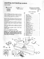
and checking contents
UI
1
7/]6_i
Wrench
1121
Wro="
3/41Wre.ch
" "
3/8'
Medium
Combination
Screwdriver
Square
Wrench
TABLE OF LOOSE PARTS
Item
Model
113 206801
Jointer/P
one carton but DOES
NOT
aner
INCLUDE
Model: 113,206931
JointerlPlaner
one carton but INCLUDES
Steei
Separate
one with
all parts from
the itlUstrat{on
is shipped
No.
complete
Steel Legs, or motor.
is shipped complete
Legs, and Motor.
in
packing
materials
and check each
and the list of Loose Parts to make
certain all items are accounted
packing material:
for,
before
discarding
any
tf any parts are missing, do not attempt
to assemble the
jointer/planer;
plug n the Dower cord or turner the switch
on until the missing parts are obtained
and are installed
correctly.
Remove the protective
oi that
metal surfaces. Use any ordinary
spot remover.
CAUTION:
Never
volatile solvents.
Apply
use gasoline,
a coat of automobile
Wipe all parts thoroughly
WARNING:
CONNECT
is applied
household
FOR
PLUG TO
naptha
to all unpainted
type grease and
or
similar
highly
wax to the table.
with
a clean, dry
YOUR
POWER
c oth.
OWN
SAFETY,
SOURCE
OUTLET
NEVER
UNTIL
ALL ASSEMBLY
STEPS ARE COMPLETE,
AND
HAVE READ
AND UNDERSTAND
THE SAFETY
OPERAT
aNAL
INSTRUCTIONS.
i
•
A
\
AD
AA (,€_._._A
Y
x
B
W
V
U
T
Description
Qty,
n
YOU
AND
A
B
*C
*D
*E
*F
"13
H
*J
*K
*L
*M
N
0
*P
*Q
R
*S
*T
*U
V
W
X
Y
Z
AA
Jainter-Plaeer ..........................
V-Belt, I/2x 52" . ......................
5/32 Setscrew Wrench ...................
1/8 Setscrew Wrench ....................
Motor Pulley, 2-1/2" Dia..................
Sliding Guard Knob .....................
Concave Plastic Washer ...................
Sliding Guard ..........................
Sliding Guard Rod ......................
Nut, 1/2 - 13 ...........................
Lockwasher, 1/2 ........................
Lockwasher, No. 10 .....................
Screw, Pan Hd,, 10 - 32 x t/4 ..............
Owners Manual .........................
Depth of Cut Handwheel
.................
Screw, Seres, I/4- 20 x 1-1/4 ..............
0n/0ff Power OutJet ....................
Washe_, 17/64 × 1/2 x 1/32 ...............
Lockwesher, E×ternaJ 1/4 .................
Screw, Pan Hd. 1/4-213 x 1/2 ...............
Jointer-Planer Belt Guard .................
Attaching Hardware (2 Nuts, 2 Botts)
_lt Guard Clips ........................
Belt Guard Support Bracket ...............
Belt Guard Support .....................
Screw Pan Hd. 10-32 x ti2 ................
1
t
t
I
1
1
2
1
!
!
1
2
2
1
1
1
1
2
2
2
1
3
1
1
2
AB
AC
AD
Motor Pulley Belt Guard ..................
Switch Key ............................
Held Dawn/Push Black ..................
1
1
2
unpacking
TABLE
Item
No,
A
8
C
D
E
and checking contents
OF LOOSE
PARTS
Parts Are
113.206931
included
Only
The Following
Model
With
Description
Qty.
Leg ..............................
End Stiffener
.......................
4
2
Side Stiffener
......................
Motor Support
.....................
Motor
............................
4
1
1
C
Package of Miscellaneous
Small Parts,
No. 67035,
Consisting of the Following:
F
G
Cord Clip ..........................
Hex Nut, 1/4 in. - 20
(approx. die, of hole 1/4 in.) ..........
Hex Nut, 5/I6 in. - 18
(approx. alia. of hole 5/1 6 in.) .........
Hex Nut, 1/2 in. - 13
(approx. die. of hole 1/2 in.) ..........
Truss Hd, Screw, !/4 in. - 20 x 5/'8 in.
long. (Top of screw is rounded)
........
Flat Washer (dia, of hole 11/32 in.) ......
Lockwasher,
1/4 in. External
Type
(approx. dia. of hole 1/4 in.) ..........
Lockwasher,
5/1 6 in. External Type
(approx. die. of hole 5/16 in,) .........
Carriage Boh, 5/16 in. - 18 x 3/4 long
...
Leveling Foot
......................
Hex Hd. Screw, 5/16 in. - 18 x 2 in .....
G
G
H
J
K
K
L
M
N
=
JL
_
2
40
A
F
7
8
40
7
40
7
3
4
3
J
K
L
N
M
, LLUH,H,
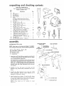
assembly
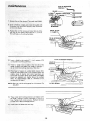
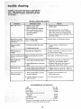
ASSEMBLING
NOTE: Steel
From among
40
40
40
8
4
TRUSS
STEEL LEGS
Legs are furnished with Model 11 3.206931.
the loose parts, find the following
Hardware:
Truss Head Screws, 1/4-20
Lockwashers,
1/4-External
Hex Nuts, 1/4-20
Hex Nuts, 1/2q3
Leveling Feet
Stiffener
assemblies.
The End Stiffeners
are placed on top and at each end of
Side Stiffener
assemb)ies
as shown. Align holes, letter
coded "'B'" in Side Stiffeners
and End Stiffeners
and
then insert 1/4-20
Truss head screws through the 9/32
diameter
holes and install
Iockwashers
and nuts and
then
tighten.
2. Assemble
Stiffeners
shown,
the
using
four
(4)
1/4-20
Legs
screws,
to
the
Side
Iockwashers
3. Assemble the Motor
Support
to the
screws, ]ockwashers
and nuts. Motor
assembled to either end of Leg set.
4.
and
End
and nuts as
Legs with
Support
1/4,20
can be
Install leveling feet as shown. To )eve,] Leg Set, loosen
nut on inside of leg and turn nut on the outside to raise
or lower feet. Adjust
all four leveling feet, if necessary,
and then tighten
nuts on the inside of leg.
NOTE:
These
adius_ment,
levelers
are
END STIFFENER
X 51//84
EXTERNAL
\
1
LOCKWASHER
_
!_ _//_
1/4_20 HEX NUT
_"
IDE STIFFENERS
1. Assemble
two (2) Side Stiffeners
together using four (4)
1/4-20
Truss head screws, Iockwasher
and nuts. Make
two (2) Side
1/4-2i
END
STIFFENER
x 5/8
HD. SCREW
not
intended
for
height
_
parts,
find
the
JO|NTERfPLANER
following
_HEX
HEAD
SCREW
18 x 3/4
x2
7 Washers; 11/32 ID
7 Hex Jam NUts, 5/16-18
2 Cord Clips
FLAT
WASHER--LOCK
2. Loosen FENCE LOCK KNOB.
J_toward the pulley.
Tilt fence
upward
a flat
from
TRUSS
HEAD
SCREW
FENCE LOCK
KNOB
1-1t4
on shaft aligning
flat surfaces
on shaft
on handwheel
_.. attach with 1-1/4
I
I
SIDE
I
STIFFENER
I
/
o
DEPTH
OF CUT
_DWHEEL
B
!
o
B
°_A
END
0
/
o
o
......
MOTOR
SUPPORT
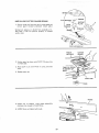
CHECKING-CUTTER:
TOOLS
NEEDED
5/32"
Jointer).
and
t/8"
AT
0
_o_.D-
THIS
BLADES
Setscrew
o
o
:_ _ A
:
-,_ -Q. 7_---_-
...._o
STIFFENER
o_
--
IN. SCREW
washer,
a lock washer and a nut on each
underneath
the stand and tighten.
5. Place handwhee]
with flat surfaces
In. screw,
114-20
WAS H E R .-""_::]
HEXNUT
and slide
3. Position machine
on Leg Set and align mounting
holes
m machine
with
holes in Leg Set letter
coded "'A".
Mount
with
three (3) 5/16-t8
x 2" Long Hex Head
Screws.
4. Place
screw
ST|FFENER
END
AND SCREWS
Wrenches
(furnished
OUTFEED
5/32 IN. SETSCREW
WRENCH
TABLE
WEDGE
with
Lead Pencil
Short
straight
edge (or head of combination
1. tnsert pencil
in space
cutterhead
guard open.
infeed
at
table
end
of
square)
cutterhead
to
hold
of
Cut
BLADE
2.
Lower
the
Handwheel.
with
the
Depth
3.
Rest the straight edge on edge on the surface of outfeed
table so it extends
across the opening
between
the
tables,
at three
positions:
near each end and at the
middle of the cutter blade.
4. Rotate
the cutterhead
by grasping the 2" alia. driven
pulley
and make sure each knife
nicks (touches)
the
straight
edge at a ! three
post on:s
tf not
f0 ow
p ocedure unde
REPLAC
NG CUTTER
BLADES
on
ppg. 21 and 22.
PENCI L
CUTTER
GUARD
5. If a cutter blade adjustment
_s not required,
check each
locking
screw of each wedge 15/32"
setscrew
wrench)
and
tighten
if
necessary,
Hold
the
pulley
while
tightening
screws and be careful that your f'ngers do not
slip off the wrench,"
iNSTALLING
SLIDING
GUARD
1/2 IN. HEX
i
NUT
:
PARTS NEEDED
I
1
1
2
1
Sliding Guard _
Sliding Guard Knob
Sliding Guard Rod
Sliding Guard Washers (one side of washer
Hex. Nut 1/2 in. _ 13
t
2
Spait toc'kwasher I/2 in.
Ext, tooth tockwashers
2
10-32xl/4
1. Screw
SLI DIt'_'GGUARD
Pan Hd. Screws
nut
all
the way
1/2 in. Iockwasher
2.
is concave)
onto
long end
of rod . . . place
next to nut.
Screw
rod alt the way into Jointer
tighten
nut.
with
short
end up...
ii
ii lul
ii
i
ill
i,u,nu, u,,,,
WASH E R
SLIDING
10-32xl/4
3,
Attach sliding
guard
and Iockwashers.
4.
Place one Sliding
support rod,
5,
Drop sliding guard onto rod..,
cave side UP on rod . . . screw
MOUNTING
to fence
Guard
with
two
machine
Washer, concave
screws
side DOWN
GUARD
KNOB
(CONCAVE
SIDE UP)
SCREWS'_
EXT. TOOTH
LOCKWASHERS
on
place other washer, conon Sliding Guard Knob.
SWITCH
PARTSNEEDED
1
2
2
2
On!Off Power Outlet
Pan Hd. Screws, 1/4-20 x t/2
Lockwashers,
External
1/4
Washers, 17/64 x 1/2 x 1/32
Attach
holes.
MOUNTING
RECOMMENDED
MOTOR AND BELT GUARDS
CRAFTSMAN
Seepage5 for recommendedmotors.
PARTS
NEEDED
4 carriage
bolts,
washers and nuts.
5/16-t8
1
1
Jointer Planer Belt Guard
Motor Pulley Belt Guard
I
!
Belt Guard
Belt Guard
i
Support
Support
ii
x
3/4
in.,
flat
washers,
lock
On/Off
outlet
to
infeed
table
3
1
1
2
Belt Guard Clips
Motor Pulley, 2q/2 in. dia.
V-Belt
Pan Head Screws 10- 32 x I/2
2
2
Hex, Hd. Screws 1/4 - 20 x t/2
Hex. Nuts t/420
TOOLS
NEEDED
Medium
Screwdriver
using
tapped
in,
in,
5/32 in, Setscrew Wrench (furnished
t/2 and 7/t6 in. Wrenches
Bracket
two
with
Jointer)
i,,pl
5/8 IN. DIA. SHAFT
PAN HD. SCREWS
t.
Place motor
on your workbench
(with key way) facing you.
2. Attach
guard
support
to
with
bracket
6/8
with
in. dia. shaft
two
screws.
NOTE:
The holes in the bracket are not threaded, but
the screws are "thread
cutting
screws" and will cut a
thread as they are tightened.
BELT
GUARD
SUPPORT
BRACKET
BELT
GUARD
SUPPORT
mbb
osse
i
:::shaft
_th
h_bl
fi_,_
CHECK MOTOR
T_,_ m_
Wewed
with
of Sh_t_
DIRECTION
OF
ROTATION
ioser'_ rn6tOr
5t32 IN.
ROTATION
SETSCREW
WRENCH
m_,_ rotate COUNTERC{.OCKWiSE whe_
fr_
PL_LL£Y
1L Piaee motor
end_
or_ your
workbench
or on floor.
2. Stared clear of motor
and plug cord into a properly
9rounded outlet
(See pa_¢ 5). f_}otice r_tation
of pulley,
If it is not tutoring COUNTERCLOCKWISE,
REMOVE
plug from out_et,
ing to instructions
and chancre rotation
of motor
furnished
with motor.
accord-
WARNING: FOR YOUR OWN SAFETY, MAKE
PLUG IS NOT CONNECTED
TO POWER SOURCE
LET WHEN CHANG!NG
ROTATION.
"_" --:--:-
;
;
__
MOUNTING
i,
:
,..............
J__JLU'L_I_I'E..L
' =!....
SLIRE
OUT.
FLUSH
HERE
MOTOR
SHAFT
KEY
&CIJ_UU['L'
....
®
MOTOR
Find fo_t 5116-t8
x 3/4"
and lockw_sher
and nuts_
carriage
bolts,
flat
washers,
2_ Attach r'_otor by iriserting carriage bolts through slots in
motor' base and thro_Jgh slOtS in motor supporL
Place a
f}al washer, lo_.kwasher and nut on each carriage bolt,
,
b_t DO NOT TIGHTf_N
nut.
">/:
/
ECZ2"3
i i_ _
J
MOTOR
MOUNT
BRACKt_T
BELT
6. Install three clips on belt guard 90 ° apart
pointing
AWAY from round opening.
with
long tabs
7, Insert belt into open end of guard.
/
/•
1_..,_-""
BE LT O UAR D C LIPS
(90 _ APART)
10
_0_
Loo_mn
_k'm two
_i_OTOR
BASE
Ct
&MP
S{.:R_WS
,,_d
/
moto_
sidewav_
u_-li
the
the putter
(>n _he £_achb_,
!2.
ir_sta!i
V,_¢}t
_:iP,
d
PUSH
1o
_h_
9, boils.
NOTE:
_t is oqly
necessary
to
to
_he be!t
to preve_t
A_t_
r:_oto_
t)_it
_nd
l_g.
W_ii8
;_
{:,_
,{'_otor
tqbteu_
r_;ts
;'H{}r_e{J with
/
b:) 8pp!y
on
/
rrlo_o_
a_sply er_ou{lh
tension
it
{fore
_;fiPP_;{t
r_
b_er{ instaH{xJ
plu{] through
h @r_c!fiy
9ua_c_ to
"B"
_}s
regtar_lu!ar
o_)@n ng m
under
switch
box and
MOTOR
CLAMP
into
the _ec-eptacie.
TO prevent
damage
to motor
a_[ach i_ to s}de stiffeners
using the two {2)co_d
3OINTER-PULLEY
INSTALLATION
w::r:::: ....
.
%
BELT
.............
i,.
ii r
.
rlr_
(BOTH
i
,,,,,,J
GUARD
I • Attach g_rd
to {_tm_d with Hex. Hd, r_:a:_ws and _*._ts_
Me_ke _k,'-rek_lt does {'_ot £(:raftu2 or_ 9u;_¢d,
2. RepI_ce we@_
CONCAVE
side up.
VENTiLATiON
HOLES
FACING
DOWNWARD
/
arid _d?,lst_d
instatt
the recta} belt
that
are _etter
coded
o_1 parj_:_ -','_.
..............
//
./
* Uf'l_31f'_t},
,:_{qd V,,b_2!t have
insert
,q"_Oto_ co!d
side _tiflene_
that
then
cord
s
/
for a}}{4_nlent
and tem:,ion
Le9 Set using
ttse hole_
r,hown
pu_!ev
dow!-_
t_nson
mouatin
pkI{Jey5
t:,_
nlotOr
, , scr4_w or_ k{_@:)_
11
BASE
SCREWS
ENDS)
i!
!
/,
2
;E
SLIDING
OUTFEEDTABLE
FENCE
GUA RD
/KNOB
INFEED
TABLE
SLIDE
8RACKET
\
,\\
\
4
CUTTER GUARD
6
DEPTH OF CUT
HANDWHEEL
ON-OFF
SWITCH
i
,,
INFEED
TABLE
1,
_
/
/J
i i1,1
DEPTH OF CUT
HANDWHEEL
DEPTH OF CUT HANDWHEEL.
Turning the
handwheel counterclockwise will lower the infeed
table to maximum depth Of !/8,.in,
DOWN
2_
SLIDING
FENCE
LOCKS AND STOPS. The fence can be
moved acrossthe Jointer to take full advantage of the
"sharpness" of the blades.
GUARD
PUSH DOWN
WHEN LOCKING
FENCE LOCK KNOB
The fence should be positioned to the extreme right
(toward pulley) but not beyond the end of the blades.
Most of the cutting [usually jointing) will be done with
the fence in this position. As the blades become dull,
the fence can be moved toward the left where the
blades are sharper,
FENCE
45°FENCE
STOP
To move the fence, loosen the Fence Lock Knob and
the Sliding Guard Knob and slide to desired position.
90 ° FENCE
STOP
Make sure SLIDE BRACKET
is even with surface of
OUTFEE D TABLE.
tf it is above or below the surface,
loosen
screws and adjust
it,
a, Always tighten fence lock knob
then tighten s_iding guard knob.
first to align fence,
FENCE LOCK
KNOB
12
\ \
SLIDE BRACKET
KNOB
b.
Before
down
c.
90 ° Fence Stop positions
To tilt fence, loosen the
stop out. Tilt
to desired
knobs.
d. To
tightening
on outfeed
set
fence
knobs,
tilt
place. Tilt
at
fence lock
table
so
90 °
knob,
hold
it does not
fence
rock.
table
e. 45 ° Fence
tables.
fence square to tables.
two knobs and pull the
angle and tighten
both
to
tables,
fence so the stop
fence back so the
loosen
the
and tighten
f.
Stop
To tilt fence
90 ° stop out,
tab{e
both
positions
knobs.
the fence
at 45 ° to
the
to 45 ° loosen the two knobs, pufl
tilt fence so the 45 ° stop rests on the
two
g. Hold fence
two knobs.
springs back ifito
stop rests on the
down
on outfeed
table and tighten
the
,1
3.
FENCE TILT
fence
to
the
SCALE.
tables.
rectly adjusted,
the scale wil!
Indicates
the angle of the
When the 90 ° fence stop is cor-
the fence will
read 90 °,
...-..-FENCE
TILT
SCALE
be 90 ° to the table and
To check for squareness, place
infeed table and check fence
position.
MAKE
SURE
90 °
SLIDE
BRACKET.
an accurate square on
while locked
at 90 °
STOP IS AGAINST
SQUARE
FENCE
FACE
tNFEED
TABLE
If fence is not square to table;
a. Slightly
knob.
loosen
fence
lock
knob
and
guard
lock
CUTTER
GUARD
b,
Loosen 90 ° stop screw with small screwdriver and
turn knurled sleeve which will cause fence to tilt.
Turn sleeve in either
with infeed table.
direction
until
fence is square
LOCKSCREW
NOTE:
If you cannot square fence
knurled sleeve, loosen three screws "A"
fence square to table.
c_
SCALE
ADJUSTING
SCREW
Tighten
knobs,
90 °
stop
Iockscrew
and
both
by turning
and adjust
,
. SCALE
TILT
fence lock
_-"7.-.,._._
d. If 90 ° reading on tilt scale does not line up with
top surface
of the slide bracket,
loosen screws
holding
scale and move _t . , . tighten
screws.
450 STO_
KNURLED _'_
13
BRACKET
k" 90 °
STOP
to know
your
HEAD
OF
SQUARE
INFEED
TABLE
FENCE
\
e.: Adjust
45 °
stop
in
the
same manner,
NOTE: Tilt scale will not require
was adjusted
for 90 ° position.
adjustment
if it
/
/
CUTTER
GUARD
CUTTER
4.
CUTTER
GUARD,
cutter head. It must
ing properly.
Check
perI¥.
a.
the
guard to
Position
Provides
always
protection
make
sure it is functioning
fence to right for maximum
b. Pass a 1/4 in, thick piece of wood
between quard and fence,
Guard
must
return
against: fence
automatically
when free
If gt_ard:does
not return
Shooting
and Maintenance
GUARD
over the
be in place and function-
width
pro-
of cut.
over cutterhead
to="rest
position'"
of: the wood.
automatically,
Sections.
see Trouble
i i
CROWNED
_.
INFEEDTABLE:MUST
LEL
TO THE
OUTFEED
ALWAYS
TABLE,
BE
CUT
PARAL-
If the cut
edge or Surface of
the workpiece
is
CROWNED,
it is an indication
that the OUTWARD
END of the tNFEED
table is HIGH
and must be
INFEED TABLE
END HIGH
adjusted.
If the cut edge or surface of the workpiece
is CONCAVE,
it is an indication that the OUTWARD
END
of the INFEED
table is LOW and must be adjusted,
Check
parallel"
the
infeed
table
to
determine
the
"out
CONCAVE
of
condition.
14
CUT
•
;i
!/:i! !_i
¸:_:_
ROTATE
BLADE OUT OF
WAY
a, Insert a pencit
hold cutterguard
in space at
open,
end
of
cutterhead
to
PENC| L
b, Place a straightedge
outfeed
table, First
other,
(large square or tong level) on
along one side than along the
c,
until
Raise
infeed
d, Sight
high
table
between
or low
it
the
straightedge.
table and straightedge
condition
of end of
It is easier to adjust the infeed
setting on your workbench.
Do not turn
adjust it.
touches
Jointer
on
to determine
infeed table.
table while
the Jointer
its side or upside
OUTFEED
TABLE
is
down
to
Attach a strip of wood to two blocks of wood 10 in. high.
Drive enough
nails into the strip so that Jointer
does
not tip over while resting on blocks.
a. Remove
motor
cord
from
b, Remove
Jointer
pulley
guard
c. Remove
Jointer
from
outlet
in switch
box.
10 IN,
d. Lower
the infeed
e, Place Jointer
andV-belt.
stand,
table,
on btocks.
OF WOOD
YOUR WORK
BENCH
,,,,u
f,
Insert
hold
a peneit
cutterguard
in space at end
of
,,
cutterhead
to
open,
g. Wrap a piece of cardboard
around cutterhead
to
protect
your fingers and the blades . . . secure
cardboard
with a piece of tape,
15
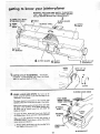
know
your
2 or 3 turns
with
loin er planer
e
o
t
m
1/2 in.-
LEVELING
STUDS
LOCKSCREWS
VIEW LOOKING
Turning
the LEVELING
the infeed table.
STUDS
witf RAISE
UP FOR PARTS IDENTIFICATION
\
or LOWER
SCREWING in the studs will RAISE the table . . .
UNSCREWING them wil_ LOWER the table.
ao With ;a 3/4 in. wrench turn
leveling studs
infeed table is parallel with straightedge,
i
•
until
b, While
hold ng studs with Wrench T1GHTEN
all
:fo0r LOCKSCREWS
. .. tighten each screw a tittle
'bit at a time
until
ali four
Screws are tight.
c.
Recheck
with
straightedge
table (in raised and lowered
outfeed tablei
to make sure i nfeed
p0s t ons) is paratlel to
i
i
i
6. ON-OFF SWITCH:
It is unlikely
that it will be
turned "ON"
accidentally,
when touched
or bumped,
because of the way it is shaped.
_J
" OFF " bys t rkl" n g
In an emergency,
it can betumed
it with the palm of the hand.
The "yellow
button"
is a key, When inserted in the
switch lever, the power may be turned ON and OFF.
When it is removed,
the power cannot be turned ON.
THIS
FEATURE
IS
INTENDED
UNAUTHOR
IZED
HAZARDOUS
OTHERS,
USE
a. _lnsert
NOTE:
TO
AND
BY
PREVENT
POSSIBLE
CHILDREN
AND
/
KEY
Key into switch.
Key {s made of yellow
plastic,
16
b, To turn
machine
on, insert finger
lever and pull end of switch out.
c. To turn machine
Never
to
OFF...
leave machine
a complete
under
switch
PUSH lever in.
unattended
until
it has come
stop.
HOLD
d. To lock switch in OFF position..,
hold switch
tN
with one hand,.
, REMOVE
key with other hand.
WARNING:
FOR YOUR OWN SAFETY, ALWAYS
LOCK THE SWITCH "OFF" WHEN MACHINE IS
NOT tN USE . . . REMOVE KEY AND KEEPtT IN
A SAFE PLACE ,.. ALSO ... IN THE EVENT OF A
POWER FAILURE
(ALL OF YOUR LIGHTS GO
OUT) TURN SWITCH OFF . . . AND REMOVE
THE KEY. THIS WILL PREVENT THE MACHINE
FROM STARTING UP AGAIN WHEN THE POWER
COMES BACK ON,
PULL
\
MOTOR
CORD
e, Plug
motor
cord
into
outlet
in
switch
t
box.
WARNING:
DON'T CONNECT
POWER CORD TO
ELECTRICAL
OUTLET IN YOUR SHOP UNTIL YOU
ARE SURE THAT MOTOR ROTATION
IS CORRECT.
(SEE PAGE 10).
POWER
CORD
17
-.....
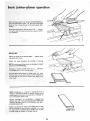
operation
F_)r your own safety ALWAYS
use the hold downlpush
blocks when JOINTING
wood that is NAR ROWER than
3"in.. _ .o t when PLANING
Wood that is TH I N N E R than
3in.
Do not
Material
plane, joint
this short
FEEDING
Hold
the
AGAINST
Feed the
or bevel wood shorter
than
is more difficult
to control
12 in.
while
being
tables
cut. Small
pieces of
or into the cutterhead
wood
can tip over on the
and can be kicked back to-
ward VOU.
For best results, take light cuts. For average
jointing,
or beveling,
a cut between
1/32 and
deep will produce the best results.
ptaning,
1[t6 in.
THE WORKPIECE
board
firmly
DOWN
the fence . . . keep
board
at a continuous
on both
tables and
fingers close together.
even rate of speed until
the cut is. made alon.g the entire length of the
hesitation
or stopping
could cause a "step"
on the edge of the board
to ride up on the:outfeed
e_lge on the board.
board. Any
to be cut
which would cause the board
table resulting in a crooked
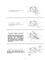
JOINTING
WOOD
THAT
IS WIDER
THAN
3 IN.
/
As the RIGHT
hand passes over the cutterhead,
remove
the LEFT
hand ...
CONTINUE
feeding while placing
the LEFT hand behind the RIGHT. Continue
feeding in
this manner "hand over hand",
until the entire length of
the board is cut. Pressure should be applied
over the
cutterhead
and outfeed table.
DO NOT FEED TOO FAST. A slow steady rate of feed
produces a smooth accurate
cut. Feeding too fast causes
a "rippled"
cut . . . makes it difficult
to guide the
workpiece
accurately
and could be hazardous.
PLANING
WOOD THAT IS THICKER
THAN 3 IN.
Always
feed WITH
THE GRAIN
whenever
possible. If
the nature of the workpiece
is such that it must be fed
AGAINST
THE GRAIN,
take very light cuts and feed
slowly,
WITH THE GRAIN
AGAINST
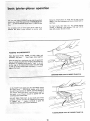
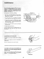
USING THE HOLD DOWN!PUSH
ALWAYS
use the hold
down/push
ING wood that is NARROWER
wood that is thinner than 3 in.
BLOCKS
blocks
than
when
JOINT-
3 in. or
planing
Grasp the hold downtpush
blocks firmly with the fingers
close together
and wrapped around the handle. Position
them flat on top of workpiece,
and push the workpiece
down
against the table to provide
a quality
cut and
minimize
the chance of a kickback_
Hold-down
pressure must also be sufficient
to prevent
hold-down/push
block sliding or slipping on the top face
of workpiece when advancing workpiece over cutter head.
Use a hand over hand
blocks being careful to
piece at all times.
motion
of the hotd down/push
maintain
control
over the work-
This means that once the workpiece
has been fed past
cutter
head onto outfeed
table,
one hold down/push
block
must always maintain
contact of workpiece
with
outfeed
table.
CAUTION;
If the
HOLD
slip while
feeding,
clean
DOWN/PUSH
rubber
surface
BLOCKS
immediately
tend to
with
sandpaper.
19
THE GRAIN
laner operation
When planing wood 3/4 in, thick and NARROWER
than
the hold
down/push
block, tilt
the hold
down/push
i block so that it ctears the top of the cutterguard
while
feed ng.
Never plane wood that is thinner
than 1/2 in ....
because
it is apt to split or shatter
and thus has a greater tendency tO kickbacki
BEY ELING
Adjust
the fence
and guard
Follow
lock
the
to the desired
angle ...tighten
fence
knobs,
same
procedure
for
jointing
or
planing.
NOTE: Removing only the corner on the edge of a board
is known as CHAMFERING.
Normally
acut
a chamfer
deePer
than
is made with
1/16
in. may
one cut.,,
therefore,
be made.
Use hold down/push
blocks for wood under 3 in. wide.
PositiOn them so you have control
of the workpiece
at
all times: and so they
do not contact the guard or the
cutter
head,
CHAMFER
BEVEL
NOTE:
Rabbeting
on a Jointer
is consid_.red
to be a
dangerous operation
because it requires removal
of the
cutter guard and increases the potential
of kickback
because of excessive depth of cut,
NEVER
ATTEMPT
TO PERFORM
A RABBETING
OPERATION
ON THIS JOINTER.
DO NOT OPERATE
JOtNTER/PLANER
WITH
CUTTERHEAD
OR BELT
GUARDS
REMOVED.
Rabbet cuts should be made on the Radial Saw or Table
Saw b_ making two cuts with the sawblade or by using
tbe,Dado
Head or Molding
Head. Rabbet cuts can also
be made using the Shaper or Portable
Router.
RABBET
2O
CUT
i _
:_i_iiii:_:i!ii_i¸
:
_/i::
'
maintenance
BLOCK OF WOOD
REPLACING
CUTTER
BLADES
WARNING:
FOR YOUR OWN SAFETY.
TURN
SWITCH "OFF" AND REMOVE PLUG FROM POWER
SOURCE OUTLET BEFORE ADJUSTING, MAINTAINING, OR LUBRICATING
YOUR JOINTER-PLANER.
1. Remove
2.
Position
beyond
3,
Lower
belt
fence
cutter
infeed
guard,
to right . , . approximately
blades . . . lock it in place,
I/4
In.
table all the way down.
4. Place block of wood 6-3/4 in. long between cutterguard and fence,
HOLD PULLEY
FIRMLY
5/32 IN.
SETSCREW
5, Hold cutterhead pulley firmly with one hand and
loosen tockscrews in each wedge using a 5/32 in.
setscrew wrench.
BLADE
LIFTER
SCREW
/
/
WRENCH
/_._
__
WEDGE
LOCKSCREW
____
TURN COUNTER
CLOCKWISE
TO LOOSEN
•.............
..........
FENCE NOT SHOWN
FOR PICTURE CLARITY
= i
I
I
SMALL SCREWDRIVER
6. While holding cutterhead pulley firmly with one hand,
gently pry up each Wedgeusing a screwdriver .
remove wedges and blades.
21
__
5/32
IN. SETSCREW
WRENCH
BLADE
LIFTER
---.-...
WEDGE
LOCKSL;REW
WEDGE
7.
RemOve the six lifter
screws,
.... : _:
(Two
under
8. Clean cutterhead,
wedges and screws
Craftsman
Gum and Pitch Remover.
oil from new blades.
9,: Replace
the
each blade.}
:
six lifter
CUTTE
SETSCREW
thoroughly
w th
Also remove the
MARK SLOTS
1, 2 AND
screws and screw them in all the
way, but do not tighten.
Mark each slot
This wil! help you in setting the blades.
1, 2, and 3.
1/8 IN, SETSCF
WRENCH
IOL Insert a blade in slot marked
1 ...
in. beyond end of the cutterhead,
So it
projects
1/8 IN.
1/16
SETSCREW
HEADOF
SQUARE
11.
"Insert
a wedge
next
to
wedge is against theblade.
do not install two locking
12,
Place
head of
square
blade
so the flat
I
\
side of the
F'ush wedge in manually
setscrews at this time. "
on outfeed
table+
LoOsen
lifter
TABLE
- screws to raise blade until it just touches square and
slightly
raises it. Gently
turn cutter
head back and
forth with
the pulley while
raising blade. The blades
should be adjusted
just
slightly
above
the outfeed
table, by
approximately
+003 in. (thickness
of an
average piece of paper).
NOTE: Sears has a knife setting gauge for this purpose. Cat.
# 9-2647
13.
"Now
install both locking setscrews and tighten
the 5/32"
setscrew
wrench)
alternately
a little
time. Tighten
both screws securely.
Recheck
tO make sure it did not change position,"
14.
Install
Other two
LIFTER
SCREW
_
(with
at a
the btade
blades the same way.
22
WRENCH
INFEED
/
INSTALLINGCUTTERGUARD
1.
Remove
remove
cotter
guard
pin from
(located
Spring must appear
feed table,
it will
upside
FLATWASHER
SPRING
SPRING
f
suPPORT/
\
pivot pin in cutter guard and
underneath
infeed
table.)
as in sketch
not perform
<_'-
......
>'"-__,Ip LATE
WASHER_
___
//_'_,
from underside
of inproperly
if installed
/ _ _. --_
__
/</_\ _<
BUSHING
_-_ _._'_
down.
VIEW
LOOKING
UP
/
2. Position guard as shown,
in infeed table.
with
3. Align SLOT
down.
TANG
4.
Replace cotter
in
pin with
PIVOT
FENCE
CUTTER
IN PLACE
GUARD
/
jr
/
,/
PIN above hole
in spring,
and press
TANG OF SPRING
IN CENTER
OF
_-T-'_._"j_._
_.
_-----"'_
' J
_
pin.
HOLE_
_.....INFEED
"-""-TABLE
-
\_
PIVOT
PIN
_-_TANG
FENCE
LIFT
5.
RAISE
end of FENCE,
rotate
clockwise
only enough to CLEAR
6.
LOWER
fence and tighten
both
guard
fence.
COUNTER
knobs.
COUNTER
CLOCKWISE
23
The normal
stationed at MAXt
"pOsition
P OStTION
CESSIVE
WEAKEN
when
is
"A"
NEVER
ROTATE
....B
E XERT
EX BECAUSE
THIS WOULD
TENSION
ON :SPRING
WHICH
COULD
OR BREAK
IT.
gUARD
I.
fence
POSITION
and SPRING.
With fence in MAXIMUM
WIDTH OF CUT position,
pass a piece of 1/4 in, thick
wood on edge (jointing
position) over cutterhead.
WIDTH
CUT
2, The guard should return
automaticall_
to its REST
position
against the fence when free of the wood.
3,
If guard does not return to its REST position, remove
cotter pin from pivot pin and remove guard, Check
pivot pin and hole..,
make sure there are no burrs,
rust, or other foreign matter.
4, Apply
a. few drops
oil to pivot pin,
5. Replace
of SAE
guard and cotter
No.
20 or No, 30 engine
pin.
If guard still does not return
to its REST position; consult your
local Sears
Retail
Store before
using the
jointer-planer.
SHARPENING
CUTTER
"A"
BLADES
The blades can be honed individually with an ordinary
oilstone.
Make sure your oilstone is not worn in the center. It
must be flat.
Be sure to remove the burr on the flat side.
If the blades are nicked, they must be replaced or reground, They can be reground several times until they
become 91t6 in. wide. Never install reground blades less
than 9/16 in. wide.
Have your knives reground by someone who is competent. Look in the "Yellow
Pages" of your telephone
directOry..,
see "Sharpening Services".
11/16 IN.
NEW BLADE
24
OF
general
maintenance
....
Keep your jointer-pianer
clean, Put a carton Or some kind
of a container
underneath
your jointer-planer
to catch
the chips. The container
should reach above the top of
the motor.
Do not allow
pitch to accumulate
fence, the cutter
guard, the cutter
Clean them with
Craftsman
Gum
Apply
and
a thin
fence
coat
so that
wood
slides
Frequently
btow
side the motor.
while
out
any dust
For motor
maintenance,
with motor.
wax to the tables
easily
On the underside
follow
If power cord is worn or cut,
have it replaced immediately,
feeding.
that
1. Dovetail
should be oiled
30 engine oil.
spacer
and
dovetail
Elevating screw
Pitch Remover).
(first
clean
occasionally
with
DOVETAIL
SPACER
AND
SLIDE
slide.
ELEVATING
2.
with
Craftsman
Gum
SCREW
and
VIEW LOOKING
UP FOR
PARTS IDENTIFICATION
25
accumulate
or damaged
The BALL
BEAR INGS in this machine
are packed with
grease at the factory. They require no further
lubrication.
parts
or No,
may
instructions
mubrication
The following
SAE No. 20
of the
jQintebpianer:
on the tables, the
head or the knives,
and Pitch Remover,
of automobile-type
the
DO not afl0w chips to accumulate
• i_
in-
furnished
in any way,
trouble
"
. i
.:
i
"
shooh g
•
•
o n
ETY, TURN SWITCH
:ROM POWER SOURCE
SHOOTING YOUR JOIN-
TROUBLE
TROUBLE
Motor will not
'r
SHOOTING
CHART
PROBABLE
CAus'E .........
I. Defective
On-Off switch.
1.
Defective
switchcord.
Defective
switchbox receptacle.
2.
2. Motor protector open, (only if
your motor isequipped with an
overload protector).
i
run.
::
'
Other cause
REMEDY
Replace
machine
defective
again.
Consult
Sears Service.
repair
this motor
unless repair
parts before
using
Any attempt
to
may create a HAZARD
is done by a qualified
service
technician.
Repair service is available
nearest Sears Store,
at your
F
Wood strikes
table after
outfeed
passing over
Blades improperly
adjusted
surface
table,
of outfeed
Re-adjust
below
biades,
see Maintenance
section.
cutter head.
|
Ripples on planed
surface:.
1, One blade set higher than
2. Feeding
wood
other.
,
1. Re-adjust
section.
too fast.
,,
,=m_l,=,l
blades,
2. Feed wood
see Maintenance
slower.
i
Planed surface
not:
Excessive gouging at end
of Cut.
: -:
I nfeed table out of adjustment.
Blades set too
. table,
90 ° and 45 °cuts
inaccurate.
!,
'
Re-adjust
high above outfeed
Fence stops not adjusted
properly.
J
2_ Fence
slide bracket
not even with
table loose.
I.
Dovetail
2,
Female
i
Cutter
guard does not
function
properly,
spacer requires adjustment.
dovetail
loose from
table.
,
table,
see Getting
your Jointer
Planer
Reset blades,
see Maintenance
! !.
Re-adjust
'
Know
fence stops
see Getting
2.
Return spring: broke,,
has been weakened.
Improper
assembly
Or sprin 9
of spring
or
see Getting
Planer
1. Tighten
screw, key
screws, key 18, see fig. 2, Parts List.
t0, see fig. 2, Parts List.
" 1. Replace spring immediately.
Maintenance
section.
2, See Maintenance
ACCESSORIES
ITEM
CAT.
NO.
Steel Legs ...............................
Floor Stand
.............................
Cutter B_ades ..............................
Power Tool Know-how
Handbooks
Radial Saw ..............................
Table Saw
..............................
9-22245
9-22216
9-2293
Knife Setting Gauge
........................
Chip Collector
............................
9-2647
9-29977
The above recommended
available at the time this
accessortes are current
manual was printed.
26
To
section.
2. Tighten
guard mounting.
RECOMMENDED
To
Planer sect=on.
slide bracket,
your Jointer
section.
i
I 1.
To Know
section.
your Jomter
2. Re-adjust
Know
lnfeed
infeed
9,2917
9-2918
and were
section.
See
repair parts
CRAFTSMAN
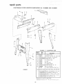
6-1/8 iNCH JOINTER-PLANER
MODEL
No. 113.206801
AND 113.206931
2
7
l
FIGURE
i't
4
LEGS PARTS LIST
Pa_
No.
Key
No.
3
1-
Description
1
67033
2
60314
• *Screw,
3
STD551225
• * Lockwasher,
4
STD541025
o'Nut,
5
67032
Stiffener,
6
62614
Leg
7
62204
8
67034
9
STD541250
• *Nut,
803835
•
10
Stiffener,
•
HARDWARE
1
--
FOR
Cord
Motor
Hex Hd. t72---
Foot,
13
Leveling
MOUNTING
le*Boft,
TOOL
I STD551031
STD523120
le*Washer,
]e'Screw,
i
J
Hardware
5/t6
MOTOR
t8x
-,- 18
Pa_ts Bag 67035
_em
fl{us,)
3/4
External
11/32 × 11/16
Hex Hd, 5/16Hex 5/t6
i£ Loose
AND
Carriage5/16-
I • *Lockwasher,
_*Nut,
27
External
20
Bag of Loose Parts (Not
STD551231
Standard
1/4
Side
Support,
I STD532507
eSupplied
Hd. 1/4 - 20 x 5/8
Hex 1/4-
Clip,
67035
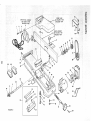
FIGURE
End
Truss
%'_ozbe P,3!c_,,_eJ
x t/16
18 x 2
iNFEED
1
2
SWtTCH BOX ASSEMBLY
SEE F_GURE 5 FOR
EXPLODED VIEW
4
3
!
TABLE
GURE
EXPLODED
3 FOR
VIEW
-
\
FENCE ASSEMBLY
SEE FIGURE 4 FOR
EXPLODED VIEW
15
]4
13
11
12
51
50
eo
48
48
\
39
38
22
16
36
45
\
46
9
/
43
11
47
53
34
41
42
FIGURE
2
25
e
CRAFTSMAN
64/8
INCH JOINTER.PLANER
MODEL No. 113.206801
AND 113.206931
FIGURE 2 PARTS LIST
Koyl p,.
Key
No.
Description
__,
1 {ST05i2505
ISTD551225
ISTD5510i2
{60381
:
118437
6
7
121013
167020
9
ISTD582062
8 121622
10
11
t2
13
118441
}3509
138879
I 60345
14
I 62023
15
16
17
18
t9
20
I ST0503103
I STD522505
!67008
!STD54!O25
iST0304520
i30646
i
26
27
28
29
Description
NO.
2
3
4
6
21
22
23
24
25
Pa_
No.
!60252
ISTD601105
60253
60254
67031
60255
37887
60096
455872
,,
*Screw,
Pan Hd. 1/4-20
x 1/2
*Lockwasher,
External I/4
*WaSher,
17/64
x 1/2 x 1/32
Outlet; On/Off
Power (See Fig. 5)
Washers
Fence Assembly,
Comp}ete (See Fig.
Knob, 1-t/2
Washer,
Sliding
Guard
_Ring, Retaining 5/8
Ring. Retaining
Bearing
Ball
Ring, Bowed Retaining
Spacer
Pulley with Set Screw, 2"' Dia. x 1/2"
V-Groove,
5/8"
Bore, Keyed
*Screw, Set, 5/16-18
x 5/16,
Soc Hd.
*Screw,
Hex. Hd. 1/4_20
x 1/2
Belt Guard, Puitey
*Nut, Hex 1/4-20
Belt, "'V" 1/2 x 52
+Pulley with Set Screw, 2-1/2
Dia. x
V-Groove,
5/8 .° Bore, Keyed
Guard-Belt,
Motor
*Screw,
Ty 23 Pan 10-32 x 1/2""
Support_Belt
Guard
Bracket-S upport
+Motor,
1216
(Supplied
With Model 113.206931
Clip "S*Wrench
Hex., 1/8
_Wrench
Hex, 5/32
Screw Mach., I/4-20
x 1-I/4
Truss
wi Lockwasher
'Standard
"lStoek
most
Hardware
Item
-
May
3)
1/2"
Only)
Item
-- May Be Purchased
Sears or S}mpsons-Sears
63410
67016
STD541031
102832
34
35
36
37
38
39
40
41
42
43
44
45
46
47
48
49
5O
51
67017
STD551025
STD551!25
STD551!50
120238
21638
18516
STD55113t
STD523117
21733
60078
STD580025
21636
37158
67019
67021
21237
132275
52
53
54
55
56
57
21450
18112
60116
21632
60117
60118
through
Retail
the
Stores
Knob, 3-1/4
Shaft, Elevating
*Nut, Hex., 5/16-18
Screw,
Set, 5/16-18
x t Full Dog Pt,,
Slotted Hd.
Sleeve
*Washer,
Plain, 17/64
I.D,
*Washer,
Split Lock, 1/4
*Washer,
Split Lock, 1/2
"Nut Hex, 1/2-13
Rod, S_iding Guard
Stud, Leveling
Lockwasher,
5/16
Screw, Hex. Hd., 5/16-18
x 1-3/4
Support _ Guard Pin
*Screw,
Mach,, 5/16-18
x 1/2-,
Hex. Hd.
Key, Woodruff,
No, 9
Arbor
Ring, Retaining
Bowed 5/8
Push Block/Hold
Down
Base
Bracket,Fence
Slide
Screw, Mach., 1/4-20
x 1, FiL Hd:
Slotted
Localty.
Hardware
or Catalog
,,
Head Assembly,
Complete
Cutter
+Blade, Cutter
*Screw,
Cap, No. 10-32 x 3/4 Soc. Hd,
Wedge, Cutter Blade
*Screw,
Set. 5/16-24
x 7/8 Soc, Hd.
*Screw,
Mach., No. 10-32 x 1/2, Fiat,
Soc Hd.
Bag of Loose Parts (not illus.)
Owners
Manual
(not iltus.)
67092
67037
Hd.
be secured
3O
3t
32
33
,
Department
Order
of
Houses.
MODEL
No, 113.206801
AND 113.206931
.
1
21
22
23
\
/
\
\
/
\
\
\
\
/
20
r\
@
--19
18
FIGURE
3
/
/
4
FIGURE
Key
No.
1
2
3
4
5
6
7
6
9
10
11
!2
Part
No.
STD561210
67015
67014
STD511107
STD551210
STD551010
38779
67011
67012
STD522505
STD551025
21812
3 INFEED
Description
Key!
Part
No. !
No.
13
14
t5
16
t7
t8
Pin, Cotter, 1/8 x 1
Guard
Table (with Name Plate)
Screw Pan Hd. 10-32 x 7/8
Lockwasher
No. 10
Washer, No. 10
Spring, Guard
Plate Support
Bushing
L_
i Screw, Cap, 1/4-20 x !/2,
: Washer, Plain, 17/64
TABLE PARTS LIST
Hex. Hd.
Plate, Tension
21422
21219
21218
STD551 t31
21635
STD523112
19
20
!:STD551031
21204
21
22
23
:_STD541025
STD551125
STD522510
!
*Standard
Hardware
items--
May Be Purchased
Locally.
3O
Description
Spacer, Dovetail
Dovetail,
Male
Dovetail,
Female
'Washer, Split Lock,
Screw, Spl.
_Screw, Cap, 5/16-18
Hex. Hd.
Washer, 5/16
Linkage Assembly
*Nut, Hex,, 1/4-20
_Washer, Split Lock,
*Screw, Cap, 1/4-20
5/16
x 1-1/4
1/4
x !, Hex. Hd.
CRAFTSMAN
1
2
3
6-1/8 INCH JOINTER-PLANER
6
4
MODEL No. 113.206801
AND 113.206931
7
10
11
12
17
16
15
_
13
FIGURE 4
F,GURE
4-21013
FENCE
ASSEMBLY
Key
No.
Part
No.
-1
2
3
21013
2t 440
21430
STD 522512
4
5
6
7
21232
21736
STD 551010
STD510802
Description
I/4-20
*Screw,
Plain,
Mach.,
21229
Body,
Fence
I3/64
x 1/2",
tncl. Key No's.
t0
STD5512t0
*Washer,
Lock,
11
STD511102
_Screw,
Mach.,
12
67009
13
STD 533725
Guard,
"Bo_t,
14
15
16
17
Full Dog
Pt., Slotted
No. 10-32 x 1/4,
21738
STD551037
47624
62331
3/8-16
x 2q/2
Head
Retainer,
Bolt
Washer 35/64
I.D.
Spacer
Knob Assembly,
Lock
,,,,,,
i
FIGURE
,
10 & ! I
Ext. Tooth
Cutter
Carriage,
Round
No. 8-32 x 1/4, Bind
Set, 1/4-20
Description
Pan Hd,, Slotted
S_otted
Screw,
No.
x 1-1/4.
Plate, Fence End
Scale, Fence Tilt
Hd.,
102817
Hex Hd.,
*Washer,
Part
No.
9
Fence Assembly
Plunger Assembly
Pin Assembly,
Stop
*Screw,
Key
t
,,, ,,,,,,,,,,,,
,,= ..........
ii
5 C ON/OFF POWER OUTLET
60381
2
\
Key
No.
1
2
3
4
5
6
FIGURE 5
Pa_
No.
60381
60375
60380
60256
60374
60377
448007
® Does Not Include
Order Separately
31
Description
• On/Off
Power Outlet Complete
Cord, Motded
Housing,
Switch
{Key, Switch
Switch,
Locking
Cover, Switch
Screw,
Pan Hd. No. 6 × 3/4
Key No 3
tf required
,,llU
6-1/8
SERVICE
MODEL
raNCH JOINTER-PLANER
Now that you have purchased your jointer-planer,
should a need
ever exist for repair parts or service, simply
contact
any
Sears Service Center and most Sears, Roebuck and Co. stores.
Be sure to provide all pertinent facts when you call or visit.
NO.
113.206801
JOINTER/PLANER
ONLY
113.206931
JOINTER!PLANER
WITH
LEGS AND MOTOR
HOW TO ORDER
REPAIR PARTS
Sold by SEARS,
Part
No. 67037
The model number of your 6-l/8
found on a plate attached to your
WHEN ORDERING
REPAIR
FOLLOWING
INFORMATION:
inch jointer-planer
base.
PARTS,
ALWAYS
witl
GIVE
be
THE
PART NUMBER
PART DESCRIPTION
MODEL NUMBER
113.206801
113.206931
NAME OF ITEM
6-1/8 INCH JOINTER-PLANER
All parts listed may be
and most Sears stores.
locally, your order will
Repair Parts Distribution
ordered from any Sears Service Center
If the parts you need are not stocked
be electronically
transmitted
to a Sears
Center for handling.
ROEBUCK
AND
Form
CO.,
No. SP4452-6
Chicago,
IL. 60684
Prin_ed
U.S.A.
in U S.A
11