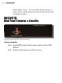
1
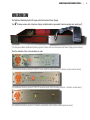
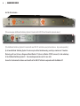
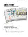
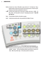
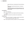
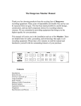
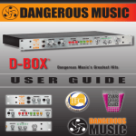
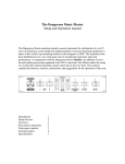
ADDITIONAL SWITCHING SYSTEM
®
For use with Monitor ST and S R
U S ER
GUI DE
SAFETY REVIEW
!
!
!
!
!
!
!
The Exclamation point within an equilateral triangle is intended to alert the user to the presence of important operating and maintenance
(servicing) instructions in the literature accompanying this product
Certain precautions should be taken when using electrical products. Please observe the safety hints by reading the manual and obtaining
qualified help if necessary to adhere to the precautions.
1. Always use a properly grounded power supply cord with this product. Please do not defeat the ground pin on the mains plug. This connection
provides earth to the chassis and signal grounds inside the device for clean and quiet operation.
2. Avoid high temperature operation in equipment racks by providing air circulation. The number one killer of electronic gear is HEAT. Vented
rack panels may look like wasted space to an interior decorator, but they look like beauty to a technician or equipment designer! If the front
panel is hot, it is roasting inside the box.
3. Avoid areas of high magnetic fields. The steel chassis is designed to shield the circuits from EMI and RFI (magnetic and radio interference).
When installing equipment in racks, it is prudent to put power amplifiers and large power supplies at least several rack spaces, if not in a
different rack, away from equipment that deals with low level signals. Separation of high level and low level equipment can pre-empt trouble
caused by heat and EMI.
4. Care should be taken to avoid liquid spills around equipment. If a spill occurs, please shut off the gear and disconnect the mains. A qualified
technician should investigate accidents to prevent further equipment damage or personnel hazards caused by spills.
5. If one is uncomfortable with opening gear and changing jumpers or making adjustments, please seek qualified help if necessary.
6. If adjustments or jumper changes are required, please disconnect the mains plug before opening the top. Dropped screws or tools on a live
circuit board can manifest themselves as burn marks and smoked components. While we feel your pain, (been there) subsequent damage is
not covered by the warranty.
Dangerous Music Incorporated reserves the right to change the specifications or modify the designs of its equipment. Sending in the
registration card is our way of keeping in touch with users of our equipment should this become necessary. Registration information is always
kept confidential and never disclosed to third parties for any reason. Company contact information is on the last page of this manual.
The CE sign on this product signifies the fact that the Additional Switching System® has been
tested and verified to conform to the applicable standards of 89/336/EEC.EN55103-1 (emissions)
EN61000-2 (immunity) and EN60065:2002 (safety requirements)
This product uses components of the types and quantities that comply with the EC RoHS
standard 2002/95/EC. A list of suppliers and materials is available from DMI. We tightly control
production to use top quality materials.
| 1
THANK YOU
Thank you for choosing products from the exciting and innovative line of
Dangerous Music recording equipment. Many years of reliable service can
be expected from our gear. This is made possible through careful design,
construction, and component choices by recording industry veterans.
The Dangerous Music Additional Switching System is designed to integrate
seamlessly into the Dangerous Music Monitor ST system. There are many
features per square inch (FPSI) packed into these half rack modules. This user’s
guide will help the engineer realize the full benefits of this system’s functionality
and use.
If you have any suggestions for future modules, feel free to forward them!
2| DANGEROUS MUSIC
TABLE OF CONTENTS
Overview
3
Remote Control
5
Monitor ST & DAC-ST Front Panel Features & Benefits 6
Monitor ST & DAC-ST Rear Panel Features & Benefits 9
Monitor ST & DAC-ST Connection and Hookup11
Monitor ST & DAC-SR Front Panel Features & Benefits 14
Monitor ST & DAC-SR Rear Panel Features & Benefits 16
Monitor ST & Uniswitch Front Panel Features & Benefits 18
Monitor ST & Uniswitch Rear Panel Features & Benefits 19
Module Installation20
Specifications
25
Warranty
26
Appendix
27
ADDITIONAL SWITCHING SYSTEM® | 3
OVERVIEW
The Additional Switching System® begins with the Rack and Power Supply.
Tip:
, It always comes with at least one factory installed module (you wouldn’t want an empty rack, would you?)
[The Dangerous Music Additional Switching System® Rack with one blank panel and Power Supply pictured above]
Then the selection of one or two modules per rack.
[The Additional Switching System® DAC-ST stereo digital to analog converter / switcher module pictured above]
[The Additional Switching System® DAC-SR surround sound digital to analog converter / switcher module above]
[The Additional Switching System® Uniswitch customizable video switcher module pictured above]
4| DANGEROUS MUSIC
And the final outcome...
[The cornucopian Additional Switching System® loaded with DAC-SR and Uniswitch pictured above]
[The Additional Switching System® loaded with one DAC-ST and blank panel pictured above. Any combo possible.]
Up to two Additional Switching System® racks may be utilized simultaneously, providing a maximum of 4 modules.
Obviously you’ll need to have a Dangerous Music Monitor ST (stereo) or Monitor ST/SR (surround) to take advantage
of the Additional Switching System®. See www.dangerousmusic.com for more intel.
So next let’s determine the features and benefits of the DAC-ST utilized in conjunction with the Monitor ST.
ADDITIONAL SWITCHING SYSTEM® | 5
REMOTE CONTROL
All Additional Switching Modules are controlled by the Dangerous ST Remote.
[Half of the Monitor ST Remote pictured above]
On the Monitor ST Remote, first use the “UP” and “DOWN” buttons to select the appropriate bank.
The Remote’s LEDs will verify which bank is active.
Then choose the input by using the “Additional Switching” 1-4 buttons.
This is how the Additional Switching remote buttons can control up to 4 devices.
See the following photo op for visual alacrity.
, If you only have one Additional Switching System®, only banks 1-2 will be selectable.
Tip:, For the DAC-ST operation, ensure that the input is set to stereo and not 5.1.
Tip:
6| DANGEROUS MUSIC
DAC-ST
Front Panel Features & Benefits
The DAC-ST expands your digital connectivity while maintaining the instantaneous control and pristine reference
standards that Dangerous Music is renowned for. The DAC-ST is a stereo D/A converter that allows the engineer
to monitor from and switch between any one of the five digital sources without interruption. The source is selected
from the Dangerous ST Remote and simultaneously routed to the Selected Digital and balanced Analog Outputs. Only
instantaneous switching between sources allows truly accurate comparisons. (“Am I A/B-ing the mix to the CD, or
to the CD Player’s Converters?”) The DAC-ST solves this conundrum elegantly, while delivering the mastering quality
conversion that you’ve come to expect from Dangerous Music.
1. S/PDIF RCA Input
5
12 3 46 7
Feature: Quick digital access for external S/PDIF devices like a field recorder, cd player, synth or laptop.
Benefit: Avoid rack diving with a flashlight duct taped about the head.
2. S/PDIF to Input 1 Button
Feature: Upon depressing the switch, SPDIF Digital Input from the RCA jack on the faceplate is routed to Input One. The default is Digital Input one, accessible via DB25 connector on the rear of the unit.
Benefit: No patchbay required! Like a 5th input.
Tip:
,
The rear Digital Inputs may be utilized for AES or S/PDIF in any combination. No transformer is
required. Simply purchase a snake wired in accordance with the pinout diagrams in the appendix
of this manual (cable does make a difference, use good quality). How is this black magic possible?
The S/PDIF standard is 500 millivolts peak to peak and the AES standard is 5 volts peak to peak.
The DAC-ST is happy receiving anywhere from 300 millivolts to 5 volts, well within tolerances, so
ADDITIONAL SWITCHING SYSTEM® | 7
you can keep on mixing the music, while we handle the technology.
Note: At the time of printing, the M-Audio 2626 was the only piece of gear known not to comply with the
standards above and therefore requires the use of a bi-directional S/PDIF to AES transformer.
3. Digital Input Selected LEDs
Feature: Visual confirmation that a specific digital source has been selected by the Monitor ST Remote. Yellow LED on = source selected. Yellow LED off = source not selected.
Benefit: Avoid putting post-its on all your gear to remember the combinations-- what? I already forgot...
Operation:The input source is selected from the Monitor ST Remote using the “Additional Switching” buttons.
4. AES LED Lock Indicator
Feature: LED lights to confirm that the D/A has locked to the selected digital input. The D/A has an instantaneous lock range of 32 kHz-192 kHz.
Benefit: Get an hour of your life back by confirming that the audible “snat” is not a digital sync issue from the DAC-ST. “Sheesh, is the source bad? A/D out of sync? The cable shorted? The input connector bunk?”
Operation:The input source is selected from the Monitor ST Remote using the “Additional Switching” buttons. The Lock LED is tethered to the Monitor ST Remote’s selections.
Tip:
,
Green LED on = active source plugged in
Red LED on = nothing plugged in or source inactive (i.e. off)
5. Analog LED Signal Present Indicators
Feature: Visual confirmation that analog audio is present on the left and right rear XLR(M) outputs.
Benefit: Avoid an hour of troubleshooting to determine whether signal is present and humiliating yourself
in front of clients. “Holy Smokes, is the source bad? The cable shorted? The input jack sour?
Is that where I put my beer?”
6. Level Trim Controls
Feature: Calibrate the analog signal levels from +12dBu to +26dBu full scale.
Benefit: Monitoring at different levels completely skews your audio judgment. Calibrate all your gear identically.
8| DANGEROUS MUSIC
Operation: To align the unit, select a 1kHz digital sine wave and feed it at the desired level. Using a
flathead screwdriver, gently turn the front panel trim pots until they measure +4 dBu at the output.
Clockwise to increase output, counterclockwise to decrease it.
Tip:
, The DAC-ST comes aligned from the factory with a maximum output level of +22dBfs
(-18
dBfs=+4 dBu). Don’t know what this all means? Contemplating audio suicide? 7. Bank LED
Input Indicators
Feature: Visual confirmation of which bus the module is occupying.
Benefit: Instantly determine which module is being controlled from the Monitor ST remote.
[Half of the Monitor ST Remote pictured above]
Operation: On the Monitor ST Remote, first use the “UP” and “DOWN” buttons to select the appropriate bank.
The Remote’s LEDs will verify which bank is active. Then choose the input by using the “Additional
Switching” 1-4 buttons. That’s how the Additional Switching remote buttons can control up to 4
devices. (More than just black magic). See the photo op above for visual alacrity.
ADDITIONAL SWITCHING SYSTEM® | 9
MONITOR ST & DAC-ST
Rear Panel Features & Benefits
Next we’ll review how to hook these audio tools up to play nicely together.
1
2 3
[The rear of the A.S.S.® DAC-ST stereo digital to analog converter / switcher module pictured on previous page]
1. Digital In/Thru
Feature: The rear panel of DAC-ST sports a DB25 connector wired to the Tascam / Digidesign AES digital
standard. Remember, this connector can be wired for AES or S/PDIF or any combination of the
two. The pinout wiring diagram resides in the appendix of this manual.
Benefit: This is a 4 channel digital input and through. Now you can (A) switch between sources while
monitoring with the same converter and (B) pass the signal forward to it’s next destination.
“So What?” (A) Here’s why this is killer. Monitoring all your digital sources through the same
converter levels the playing field. In other words, conduct comparative listening through
the identical pristine audio converter.
Example: “What’s all that extra top end on the CD pressing?” Might just be “crunch” generated
from the CD player’s D/A converter. “Why can’t I pinpoint the ride cymbal?” Jitter
from that cheap CD player could be smearing the image.
Tip:
, Dangerous Music is so concerned about the inviolability of your audio, that the DAC-ST
will actually clean up jitter from squalid incoming sources and pass it through with
defined edges. The instantaneous lock range is 32 kHz to 192 kHz.
“So What?” (B) Passing the signal forward opens up a myriad of possibilities.
Example: •Monitor the main mix from Pro Tools. Pass this on to external hardware.
10| DANGEROUS MUSIC
•Compare the effected version. Pass through back into Pro Tools and effect with plugins.
•Compare against the original and hardware effected versions. Pass through to an
external recorder.
•Compare the output of the final recorder with all the aforementioned sources. Now
make accurate, critical decisions based on true comparisons. Pass through to a digital
meter or see tip below.
2. Selected Digital Out
Feature: Connect a digital meter here.
Benefit: Every time you change DAC-ST sources, the digital meter will follow the audio currently being
monitored.
Tip:
, Connect to an external recorder to create multiple versions for comparative listening.
3. Analog Out (stereo)
Feature: Connect to an input on the Monitor ST. Level calibration is made with the “Level Trims Controls.”
The DAC-ST comes aligned from the factory to -18 dBFS = +4 dBU.
Benefit: Expansion and digital source monitoring for your Monitor ST rig. Don’t worry about outgrowing it!
ADDITIONAL SWITCHING SYSTEM® |11
MONITOR ST & DAC-ST
Connection and Hookup
1
2 3
[The rear of the A.S.S.® DAC-ST stereo digital to analog converter / switcher module pictured above]
A B C D
EXAMPLE A:
AES DIGITAL I/O SNAKE
[AES TD DB25-XLR(F) & XLR(M)]
EXAMPLE B:
AES CABLE
EXAMPLE C:
MIC CABLE
[AES XLR(F)-XLR(M)]
[ANALOG XLR(F)-XLR(M)]
E
EXAMPLE E:
AES to S/PDIF CABLE
[DIGITAL XLR(M)-RCA]
(Cables purchased separately)
EXAMPLE D:
ANALOG SNAKE
[ANALOG DB25-XLR(F)]
12| DANGEROUS MUSIC
1. D-Sub to Digital in/out snake:
Connects 4 stereo pairs of digital i/o.
Example: 25-pin D-Sub on one end, eight XLRs on the other (4 female connectors for stereo input and 4
What:
male connectors for stereo out/thru). See photo A for visual confirmation and Appendix for wiring
diagram. This conforms to the Tascam / Digi wiring standard.
, Remember, this may be wired for AES or S/PDIF or any combination, without transformers. Keeping
digital cables or a snake on hand to flip the connectors makes this easy (see photo E).
Tip: , Buy good cable! It’s the superhighway for audio electrons. Go Mogami.
Tip:
2. AES XLR(F)-XLR(M) Cable:
What:
Connects to an external digital meter and follows current monitor source.
Example:Use 110 ohm shielded cable. (See photo B for visceral confirmation.)
Tip:
, Optionally, connect to an external recorder to create multiple versions for comparative listening.
3. Two XLR(F)-XLR(M) Analog Cables or connect directly XLR(F)-DB25 snake:
What:
Connects the two analog XLR outputs from the DAC-ST to the D-Sub connector on the Monitor
ST. These two outputs from the DAC-ST are joining other device’s outputs, that are meeting at
the D-Sub.
Example:Use shielded cable or depending on positioning (photo C), wire directly with analog XLR(F)-DB25
snake. (See photo D for visceral confirmation.)
8
[The rear of the Monitor-ST stereo monitor control system pictured above]
[The rear of the DAC-ST in Additional Switching Rack® pictured above]
7
56
ADDITIONAL SWITCHING SYSTEM® |13
4
[The rear of the Monitor ST/SR Remote pictured above]
4 & 5. Shielded Ethernet Cable:
What:
Ethernet CAT 5e shielded cable connects 4 and 5, bridging the Monitor ST remote and Additional
Switching Rack®.
Example:The remote connects to the Additional Switching Rack® with shielded CAT 5-e cable. It may
safely be up to 100 feet long. Come out of the remote, into the “REMOTE IN” jack.
,
Tip:
Don’t plug this into a router or computer unless you want to see the chip set blow sky high and
void the warranty! It is not an Ethernet connection. An RJ-45 jack was used because this allows
one to procure cables and extensions without a fuss. Please only use shielded Cat 5-e cable and
connectors.
6 & 7. Shielded Ethernet Cable:
What:
Ethernet CAT 5e shielded cable connects 6 and 7, bridging the Additional Switching Rack® and
Monitor ST.
Caution: Don’t plug this into a router or computer unless you want to see the chip set blow sky high and
void the warranty! It is not an Ethernet connection. An RJ-45 jack was used because this allows
one to procure cables and extensions without a fuss. Please only use shielded Cat 5-e cable and
connectors.
Example: Utilizing the long cable provided, the Remote’s Out (4) connects to the “REMOTE IN” on the
Additional Switching System’s chassis. The Additional Switching System’s “REMOTE THRU”
connects via the short Ethernet cable provided to the Monitor ST’s “REMOTE IN”.
8. Review from previous section: “3. Two XLR(F)-XLR(M) Analog Cables...”
14| DANGEROUS MUSIC
DAC-SR
Front Panel Features & Benefits
The DAC-SR expands your digital connectivity while maintaining the instantaneous control and pristine reference
standards that Dangerous Music is renowned for. The DAC-SR is a 6 channel D/A converter that allows the engineer to
monitor from and switch between any one of the four digital 5.1 sources without interruption. The source is selected
from the Dangerous ST-SR Remote and simultaneously routed to the balanced Analog Outputs. Only instantaneous
switching between sources allows truly accurate comparisons. (“Am I A/B-ing the mix to the DVD, or to the DVD
Player’s Converters?”) The DAC-SR solves this conundrum elegantly, while delivering the mastering quality conversion
that you’ve come to expect from Dangerous Music.
1 2 3 45
[The Dangerous Music DAC-SR front panel pictured above]
6
[The Dangerous Music
DAC-SR internal circuit board
pictured left]
You know... the guts!
ADDITIONAL SWITCHING SYSTEM® |15
1. Digital Input Selected LEDs
Feature: Visual confirmation that a specific digital source has been selected by the Monitor ST-SR
Remote. Yellow LED on = source selected. Yellow LED off = source not selected.
Benefit: Avoid putting post-its on all your gear to remember the combinations-- what? I already forgot...
2. Input Button
Feature: This button toggles Input 4 between TOSLINK multichannel ADAT and stereo optical.
Benefit: Provides monitoring of non ADAT, stereo optical sources.
Tip:
,
Note: Plug in your Mac’s optical digital out and hear what’s going on! You will need your own cable.
Stereo optical (S/PDIF) is different than multichannel optical (ADAT).
3. LED Signal Present Indicators
Feature: Visual confirmation provided for the input selected.
Benefit: Avoid an hour of troubleshooting to determine whether signal is present and humiliating yourself in front of clients. “Holy Smokes, is the source bad? The cable shorted? The input jack sour?”
4. Digital LED Lock Indicator
Feature: The LED lights to confirm that the D/A has locked to the selected digital input. [The D/A has an
instantaneous lock range of 32 kHz-192 kHz.]
Benefit: Get an hour of your life back by confirming that the audible “snat” is not a digital sync issue
from the DAC-SR. Avoid embarrassing scenes in front of clients. “Well now Higgins, is the
source bad? A/D out of sync? The cable shorted? The input connector bunk?”
Operation:The input source is selected from the Monitor ST-SR Remote using the “Additional Switching” buttons. The Lock LED is tethered to the Monitor ST-SR Remote’s selections.
Tip:
,
Green LED on = active source plugged in
Red LED on = nothing plugged in or the source is inactive (i.e. off)
5. Bank LED Input Indicators
Feature: Visual confirmation of which bus the module is occupying.
Benefit: Instantly determine which module is being controlled from the Monitor ST-SR remote.
16| DANGEROUS MUSIC
Operation:On the Monitor ST Remote, first use the “UP” and “DOWN” buttons to select the appropriate
bank. The Remote’s LEDs will verify which bank is active. Then choose the input by using the
“Additional Switching” 1-4 buttons. That’s how the Additional Switching remote buttons can
control up to 4 devices. (More than just black magic). See the Remote ST-SR section for photo
ops and visual alacrity.
6. Level Trim Controls
Feature: If you have experience in this department, calibrate the digital signal levels up to a maximum
output of +26 dBu (-22dBFS = +4dBU, or 1.23 vRMS).
Benefit: Monitoring at different levels completely skews your audio judgment. Calibrate all your gear
identically.
Operation: To align the unit, remove the lid as outlined in the “module installation” section. Locate the 6
alignment pots (circled in the photo op above). These are NOT to be confused with the 6 DC offset
nulls below them. Select a 1kHz digital sine wave and feed it at the desired level. Using a small
tweaker flathead screwdriver, gently turn the internal trim pots until they measure +4 dBu at the
output.
Tip:
, The DAC-SR comes aligned from the factory to -18 dBFS = +4 dBU.
Caution: To avoid risk of electrical shock, unplug the unit from power before removing the lid. Exercise
caution as frequently as possible.
Note:
See the module installation section for photos.
DAC-SR
Rear Panel Features & Benefits
1 2 3
[The Dangerous Music DAC-SR rear panel pictured above, installed in the Additional Switching System Rack]
ADDITIONAL SWITCHING SYSTEM® |17
1. AES & S/PDIF Digital In/Thru
Feature: The rear panel of DAC-SR sports two 25 pin D-Sub connectors (commonly called DB25s) wired to
the Tascam / Avid AES digital standard. Remember, these connectors can be wired for AES or S/
PDIF or any combination of the two. Up to a 24 bit depth with sampling rates from 32 kHz-192
kHz are supported. (The pinout wiring diagram resides in the appendix of this manual.)
Benefit: (A) Provides instantaneous switching between two 5.1 sets of digital inputs wired for AES or S/
PDIF (flexible like a yoga disciple). (B) Pass the signal forward to it’s next destination.
“So What?” (A) Monitoring all your digital sources through the same converter levels the playing field. In
other words, conduct comparative listening through the identical pristine audio converter.
Example: “What’s all that extra top end on the DVD pressing?” Might just be “crunch” generated from the
DVD player’s D/A converter. “Why can’t I pinpoint the ride cymbal?” Jitter from that cheap DVD
player could be smearing the image.
Tip:
, Dangerous Music is so concerned about the inviolability of your audio, that the DAC-SR will
actually clean up jitter from squalid incoming sources and pass it through with defined edges. The
instantaneous lock range is 32 kHz to 192 kHz.
“So What?” (B) Passing the signal forward opens up a myriad of possibilities.
Example: •Monitor the main mix from Pro Tools. Pass this on to external hardware.
•Compare the effected version. Pass through back into Pro Tools and effect with plug-ins.
•Compare against the original and hardware effected versions. Pass through to an external recorder.
•Compare the output of the final recorder with all the aforementioned sources. Now make accurate,
critical decisions based on true comparisons. Pass through to a digital meter or see tip below.
Tip:
,
Note: The rear Digital Inputs may be utilized for AES or S/PDIF in any combination. Save your cash! No
transformer is required. Simply purchase a snake wired in accordance with the pinout diagrams in
the appendix of this manual (cable does make a difference, use good quality). How is this black
magic possible? The S/PDIF standard is 500 millivolts peak to peak and the AES standard is 5
volts peak to peak. The DAC-ST is happy receiving anywhere from 300 millivolts to 5 volts, well
within tolerances, so you can keep on mixing the music, while we handle the technology.
At the time of printing, the M-Audio 2626 was the only piece of gear known not to comply with the
standards above and therefore requires the use of a bi-directional S/PDIF to AES transformer.
1. AES & S/PDIF Digital In
18| DANGEROUS MUSIC
Feature: 2A. TOSLINK Multi-channel Inputs
Feature: Two TOSLINK inputs accept optical multi-channel feeds of up to 24 bits with sampling rates
from 32 kHz-96 kHz.
Benefit: Accept multiple rates with no conversion and avoid the crack, snapple, pop of digital reclocking.
2B. Digital Input 4
Feature: Input 4 is switchable between stereo optical (S/PDIF) and multichannel audio. Benefit: Forget repatching, just hit the button and monitor your confidence mix through the same pristine
converters.
Operation: Utilize the front panel switch (2 in former photo op) to toggle between functions.
Tip:
, The DAC-SR can be calibrated to match any chosen studio reference level. See previous section
for “how to” details.
3. Analog Output
Feature: Selected 5.1 source outputs here.
Benefit: Expand your Monitor SR rig with up to two Additional Switching System racks loaded with 4
modules. Perpetual expansion!
Operation: Connect this DB25 connector to the Monitor SR.
ADDITIONAL SWITCHING SYSTEM® |19
UNISWITCH
Front Panel Features & Benefits
Involved with music for television, film scoring or broadcast sound? Undoubtedly you own as many video sources as
audio. The Uniswitch provides instantaneous switching between multiple video sources, all controlled from the versatile
Dangerous Remote. The Uniswitch controls any Gefen 4x1 switcher equipped with the RS232 input connector. In fact,
the techs at Dangerous Music can customize the Uniswitch to control ANY RS232 device. From Studer Tape Machines
to Routers to Lighting... Video and audio elegance from Dangerous Music.
1
2
[The Dangerous Music Uniswitch front panel pictured above]
1. Video Selected Input LEDs
Feature: Visual confirmation that a specific video source has been selected by the Monitor ST Remote. Yellow LED on = source selected. Yellow LED off = source not selected.
Benefit: Avoid putting post-its on all your gear to remember the combinations-- what? I already forgot.
Operation:The input source is selected from the Monitor ST Remote using the “Additional Switching” buttons. See remote section for more specifics.
Tip:
,
The Uniswitch input LED’s will track with the Gefen’s input indicator LED’s.
2. Bank LED Input Indicators
Feature: Visual confirmation of which bus the module is occupying.
Benefit: Instantly determine which module is being controlled from the Monitor ST remote.
Operation:On the Monitor ST Remote, first use the “UP” and “DOWN” buttons to select the appropriate
bank. The Remote’s LEDs will verify which bank is active. Then choose the input by using the
20| DANGEROUS MUSIC
“Additional Switching” 1-4 buttons. That’s how the Additional Switching remote buttons can
control up to 4 devices. (More than just black magic). Refer to the remote section for more 411
(i.e. information) and a photo op.
UNISWITCH
Rear Panel Features & Benefits
1
[The Dangerous Music Uniswitch rear panel pictured above]
1. RS232 9 pin female DSub
Feature: One simple RS232 9 pin female DSub output, connects to any Gefen box that has an RS232
remote input.
Benefit: Compatible with multiple Gefen products to fulfill any video scenario.
ADDITIONAL SWITCHING SYSTEM® |21
21| DANGEROUS MUSIC
MODULE INSTALLATION
1
2
3
6
4 5
7
8
9
10
22 | Enicaper ficaed susta nondin is es nonim et dolore
ADDITIONAL SWITCHING SYSTEM® |22
13
12
11 12
13
ADDITIONAL SWITCHING SYSTEM® |23
23| DANGEROUS MUSIC
11
15
12
16
16
14
ADDITIONAL SWITCHING SYSTEM® |24
MODULE INSTALLATION CONTINUED...
Tip: ,This is only necessary if you purchase additional modules for a rack you already own. Each module will have specific installation instructions, the following serves as an example.
STEP 1. Organize all the loot:
Confirm you have (as numbered in the previous photo ops):
1. DAC-ST board with rear panel
2. DAC-ST front panel
3. Four #6-32 x 3/8” pan head stainless steel machine screws (board to chassis)
4. Four #4-40 x 1/4” flat head stainless steel machine screws (preexisting front panel to chassis)
5. Four #6-32 x 1/4” flat head black stainless machine screws (preexisting rear panel to chassis)
6. Two 12 pin smaller flat ribbon cables
7. One 20 pin larger IDC ribbon cable
8. The A.S.S. Rack
9. Blank panel in front and back
10. Power supply (preexisting from your original Additional Switching System®)
Tip:
, Now is not the time to start drinking. Wait until you have this bad boy assembled to celebrate.
STEP 2. Preparation
Ensure that the unit is powered down and NOT plugged into the wall. Go grab a #2 and #1
phillips screwdriver from your tool box.
Discharge any static electricity you may have picked up by touching a metal chair or table
STEP 3. Removing the lid and front and rear blank panels
•Using a #2 phillips head screwdriver (not supplied), carefully first remove the 8 black screws
securing the lid (14).
•Using a #1 phillips head screwdriver, remove the four #4-40 x 1/4” silver screws in the blank face
plate (9).
25| DANGEROUS MUSIC
Tip:
•Using a #2 phillips head screwdriver, remove the four #6-32 x 1/4” black screws in the rear plate
(5).
, Put the screws somewhere where they won’t roll into the shag carpet like a recycled Trader Joes
Salsa Cruda container. You’ll need these in a minute.
STEP 4. Installing the board •Where you just removed the rear panel, slide the board and rear panel assembly (1) through the
rectangular opening.
•Attach it to the rear with the four #6-32 x 1/4” black screws removed from rear blank (5).
•Screw board down (13) with four #6-32 x 3/8” machine screws (3).
•Attach the DAC-ST face (2) with the four #4-40 x 1/4” silver screws removed from the front blank
(4).
STEP 5. Wiring the goods •Before attaching the 20 pin larger IDC ribbon cable (7), orient the A.S.S. exactly as in the prior
photo op and note the red trace, indicating pin 1. Now, connect the ribbon cable to the DAC-ST
PCB (11) with the red trace on the left. Then, connect it to the control PCB (15) with the red trace
on the lower half of the ribbon. Note the gentle fold in the ribbon.
•Before attaching the 12 pin smaller flat ribbon cables (6) orient your A.S.S. exactly as in the prior
photo op. Now, noting the blue side of the ribbon connector, connect them between main (12) and
front PCB’s (16).
• Attach the 2-pin Molex connector extending from the front panel PCB (2) to the 2-pin header on
the Main PCB (15). It will click into place.
STEP 6. Clean up
•Screw the lid back on with those 8 black screws you put in the Salsa container.
•You’re done! Do a little victory dance and crack that beer now.
Tip:
, If you are uncomfortable performing the installation yourself, Dangerous can perform it safely for
you at the factory.
ADDITIONAL SWITCHING SYSTEM® |26
SPECIFICATIONS*
Frequency response.................................................................................................... 1Hz – 100 kHz within 0.2dB
Clock Range.................................................................................................................
32kHz-192kHz
THD+Noise -14dBfs...................................................................................................
0.003%
THD+Noise 0dBfs........................................................................................................
0.001%
IMD60 4:1....................................................................................................................
0.003%
Low Pass Filter............................................................................................................ 57Hz, 3 pole Bessel/Chebyshev hybrid
Interchannel crosstalk at 1kHz.................................................................................
>102dB
Dynamic range.............................................................................................................
>105dB
Maximum level (for -20dBu referenced systems)................................................
+24.5dBu
Nominal operating level..............................................................................................
+4dBu
Power consumption.....................................................................................................
30 watts
*Analog performance at 48kHz sample rate test conditions, -14dBfs = +4dBu unless noted: 10Hz-20kHz +0/-0.2dB
27| DANGEROUS MUSIC
WARRANTY
Free 2 year extended warranty with online registration.
Standard warranty: 90 days parts and labor, subject to inspection.
Does not include damage incurred through shipping damage, abusive operation or modifications/attempted repair by
unauthorized technicians.
USA
Dangerous Music Inc.
231 Stevens Road
Edmeston, NY 13335
EUROPE
Dangerous Music Europe
Stieleichenweg 55
50999 Cologne, Germany
Fon: +49 2236 393731
Email: [email protected]
E-mail: [email protected]
Dangerous Music, Inc. reserves the right to alter the software and design of their equipment.
If after reading the manual more information for an application is needed, please contact us via email for the quickest
response.
•Factory contact for RA# must occur before shipping a unit to us for service.
•Please keep the original cartons in case storage or transportation of units is required.
•Always insure shipment as these damages are not covered by the warranty.
•Thank you for actually reading the manual. Now go make some Dangerous Music!
-Revision 1 May 2013 (marek)
ADDITIONAL SWITCHING SYSTEM® |28
APPENDIX
AES/EBU DB25
8 CHANNEL BIDIRECTIONAL IN & OUT
Note: the four AES inputs and four pass-throughs are on a single 25 pin D-subminiature connector. For reference,
and for those intrepid solder jockeys who wish to build their own cables, the pin out diagram of the Digital in/thru
connector is shown above. This conforms to the Tascam wiring standard.
BLOCK DIAGRAM OVERVIEW OF THE DAC-ST SIGNAL FLOW