1
183172520003
Owner's
Manual
CRAFTSMAN®
ALL-IN-ONE
CUTTING TOOL
Model No.
183.172521
®
Important
Safety
®
Notice
IA WARNING
I
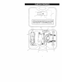
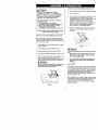
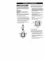
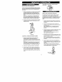
Always have one hand firmly
placed on the tool body while
operating. Never operate the
tool by holding only the tool
handle,
• Safety Instructions
• Accessories
CAUTION:
Before using this Cutting
Tool, read this manual and
follow all its Safety Rules
and Operating
Instructions.
•
•
•
•
Assembly
Operation
Maintenance
Parts List
• Espanol
Sears, Roebuck and Co., Hoffman
Part. No. 183172520003
Rev. 3
06/27/02
Estates, IL 60179 USA
SECTION
Warranty ........................................
Product Specifications ......................
Power Tool Safety ............................
Cutting Tool Safety ...........................
Electrical Requirements & Safety ........
Accessories ....................................
PAGE
2
2
3
4
5
6
SECTION
Carton Contents ..............................
Know Your Cutting Tool ....................
Assembly & Operation ......................
Maintenance ...................................
Repair Parts ...................................
Parts & Service Availability ................
PAGE
6, 7
8
9 - 18
18
19 - 25
26
FULL ONE YEAR WARRANTY
tf this Cutting Tool fails due to a defect in material or workmanshipwithin one year of date of
purchase,Sears will at itsoptionrepairor replace it free of charge.
Return this Cutting Tool to a Sears Service Center for repair, or to place of purchase for
replacement.
This warrantygivesyou specificlegal rights,and youmay also have other rights whichmay vary
from state to state.
Sears, Roebuckand Co., Dept. 817 WA, Hoffman Estates, IL 60179
IA WARNING
I
Some dust created by power sanding, sawing, grinding, drilling and other construction activities contains
chemicals known (to the State of California) to cause cancer, birth defects or other reproductive harm. Some
examples of these chemicals are:
•
Lead from lead-based paints
,, Crystalline silica from bricks, cement and other masonry products
•
Arsenic and chromium from chemically treated lumber
Your risk from these exposures varies, depending on how often you do this type of work. To reduce your expos,
to these chemicals, work in a well ventilated area and work with approved safety equipment such as those dust
masks that are specially designed to filter out microscopic particles.
Motor Rating ......................
Amperes ...........................
2 Speeds (no load) ..............
120V, 60Hz, AC
5.0 Amperes
20000 & 30000 RPM
Motor Horsepower ......
Weight .....................
314HP (Maximum Developed)
1.7 kg
IJk WARNINGI
To avoid electrical hazards, fire hazards or damage to the cutting tool, use proper circuit protection.
This cutting tool is wired at the factory for 110-t20 Volt operation. It must be connected to a 110-120 Volt / 15
Ampere time delay fuse or curcuit breaker. To avoid shock or fire, replace power cord immediately if it is worn,
or damaged in any way.
Before using your cutting tool, it is critical that you read and understand
rules could result in serious injury to you or damage to the cutting tool.
these safety rules. Failure to follow th_
IA WARNINGI
Before
using
your cutting
tool,
it is critical
that
you
read
Failure to follow these rules could result in serious injury
and
understand
these
safety
rules.
to you or damage to the cutting tool.
Good safety practices are a combination of common
sense, staying alert and understanding how to use your
power tool. To avoid mistakes that could cause sedous
injury, do not plug in your cutting tool until you have read
and understood the following safety rules:
15. REMOVE ADJUSTING KEYS AND WRENCHES.
Form the habit of checking to see that keys and
adjusting wrenches are removed from the tool before
turning "ON".
1.
16. NEVER LEAVE TOOL RUNNING UNATTENDED.
TURN THE POWER "OFF". Do not leave the tool
before it comes to a complete stop.
READ and become familiar with this entire Owner's
Manual. LEARN the toors applications, limitations and
possible hazards.
IA WARNINGI
Look for this symbol that identifies important safely
precautions. It means CAUTION! BECOME ALERTI
YOUR SAFETY IS INVOLVED!
3.
KEEP GUARDS IN PLACE and in working order.
4.
DO NOT USE IN A DANGEROUS ENVIRONMENT
such as damp or wet locations or exposure to rain.
Keep work area well lighted.
5.
DO NOT use power tools in the presence of
flammable liquids or gases.
6.
KEEP WORK AREA CLEAN. Cluttered areas and
workbenches invite accidents.
7.
KEEP CHILDREN AWAY. All visitors should be kept
at a safe distance from the work area.
8.
DO NOT FORCE THE TOOL. It will do the job better
and safer at the rate for which it was designed.
9.
USE THE RIGHT TOOL. Do not force the tool or
attachment to do a job for which it is not designed.
17. NEVER STAND ON TOOL. Serious injury could occur
if the tool is tipped or if the cutting tool is
unintentionally contacted.
18. DO NOT OVER REACH. Keep proper footing and
balance at all times.
19. MAINTAIN TOOLS WITH CARE. Keep tools sharp
and clean for most efficient and safest performance,
Follow instructions for lubricating and changing
accessories.
20. CHECK FOR DAMAGED PARTS. Before further use
of the tool, a guard or other part that is damaged
should be carefully checked to ensure itwill operate
properly and perform its intended function. Check for
alignment of moving parts, binding of moving parts,
mounting and any other conditions that may affect its
safe operation. A guard or other part that is damaged
should be properly repaired or replaced.
21. MAKE WORKSHOP CHILD PROOF with padlocks,
master switches or by removing starter keys.
22. DO NOT operate the tool if you are under the
influence of any drugs, alcohol or medication that
could impair your ability to use the tool safely.
10. WEAR PROPER APPAREL. DO NOT wear loose
clothing, gloves, neckties, rings, bracelets or other
jewelry that may get caught in moving parts. Non-slip
footwear is recommended. Wear protective hair
covering to contain long hair.
23. USE DUST COLLECTION SYSTEM wherever
possible. Dust generated from certain materials can
be hazardous to your health and in some cases, a fire
hazard. Always operate the power tool in a well
ventilated area with adequate dust removal.
11. WEAR A FACE MASK OR DUST MASK, Sawing,
cutting, drilling and sanding operations produce
hazardous dust.
24. ALWAYS WEAR EYE PROTECTION. Any power tool
can throw foreign objects into
your eyes which could cause
permanent eye damage.
ALWAYS wear safety goggles
(not glasses) that comply with
ANSI safety standard Z87.1. Everyday glasses have
only impact resistant lenses. They ARE NOT safety
glasses. Safety goggles are available at Sears,
12. DISCONNECT TOOLS FROM THE POWER
SOURCE before servicing and when changing
accessories such as blades, bits, cutters, etc.
13. REDUCE THE RISK OF UNINTENTIONAL
STARTING. Make sure the switch is in the "OFF"
position before plugging into the power source.
14. USE ONLY RECOMMENDED ACCESSORIES.
Consult the Owner's Manual for recommended
accessories. The use of improper accessories may
cause injury to you or damage to the tool.
SAVE THESE INSTRUCTIONS
IAWARNING
I
Glasses or goggles not in compliance with ANSI
Z87,1 could cause serious injury when they break.
FOR REFERENCE
IA WARNINGn
For your safety, do not plug in your cutting tool or try
to use any accessory until it is completely assembled
and installed according to these instructions, and
until you have read and understood this Owner's
Manual,
11. NEVER HOLD THE WORKPIECE IN ONE HAND
while operating the tool with the other hand.
Failure to follow these safety rules will result in risk of
serious injury.
13. NEVER START THE TOOL WHEN THE BIT IS
TOUCHING THE WORKPIECE. The bit may catch
the workpiece causing loss of control.
1.
2.
3.
WEAR EYE PROTECTION. This high speed tool will
throw particles from the workpiece during operation.
Make sure safety glasses have side shields.
USE FACE OR DUST MASK along with safety
goggles if cutting or routing operation is dusty. Make
sure work area is well ventilated.
USE HEARING PROTECTION,
extended periods of operation.
14. ALWAYS HOLD THE TOOL WITH TWO HANDS
DURING START-UP AND OPERATION. When
starting, motor torque will cause the tool to twist.
15. TURN OFF ALL CIRCUIT BREAKERS AND
REMOVE ALL FUSES in the work area when cuttir
into walls or blind areas.
particularly during
4.
NEVER USE DULL OR DAMAGED BITS. Damaged
bits can break without warning. Dull bits may overload
the motor, cut slowly and are difficult to control. They
will also overheat and possibly break.
5.
ALWAYS MAKE SURE THE WORKPIECE IS FREE
OF NAILS AND OTHER FOREIGN OBJECTS. If the
bit strikes a nail it will jump sideways and possibly
break.
6.
DO NOT USE THIS TOOL FOR DRILLING HOLES.
it is NOT intended to be used as a drill.
7.
ALLOW CLEARANCE UNDER WORKPIECE for bit
to travel. Never place workpiece on hard surfaces
such as concrete etc. The bit may jump or break when
contacting a surface other than the one being cut.
8.
ALWAYS SET THE DEPTH GUIDE TO THE
APPROPRIATE DEPTH. Use tool with the depth
guide fiat against the work surface for better control of
the tool.
9.
12. NEVER PLACE HANDS IN THE PATH OF THE
CU'I-rER AND UNDER THE WORKPIECE.
NEVER USE THE TOOL WITHOUT THE SOLE
PLATE, PRECISION HANDLE OR ROUTER BASE
attached and appropriately adjusted.
16. ALWAYS HOLD THE TOOL BY THE INSULATED
GRIPPING SURFACES ON THE BODY OF THE
TOOL where there is any possibility of the cutting b
contacting hidden electrical wires or the cord of the
tool. Contact with "live"wires will make exposed me
parts of the tool "live"causing an electrical shock to
the operator.
17. WHEN CUTTING DRYWALL ELECTRICAL OUTLI
OPENINGS using the outlet as a guide, always cut
a counter clockwise direction. The natural tendency
the tool to pull to the left will cause a "hugging" actk
toward the outlet box, resulting in a neater cut.
18. NEVER LAY THE TOOL DOWN UNTIL THE
CUTTING BIT COMES TO A COMPLETE STOP. [
spinning bit can come in contact with the surface ar
pull it out of your control.
19. NEVER TOUCH THE CUTTING BIT IMMEDIATEL"
AFTER USE. The bit will be too hot to be handled
bare hands and will burn your fingers.
20. ALWAYs RE-TIGHTEN COLLET AND ALL
ADJUSTMENTS before starting the tool after a cutt
bit or accessory has been changed. Loose bits and
adjustments can cause unexpected shifting of the tc
resulting in loss of control and injury from the bit or
cutting tool being thrown
10. ALWAYS CLAMP WORKPIECE TO HOLD IT
STEADY WHEN CUTTING. This will free both hands
for operating the tool.
SAVE THESEINSTRUCTIONS
FOR REFERENCE
DleJlJ :] ! i
I_ _lJ
i;|
I It] _
This cutting tool is double insulated to protect you from
electrical shock.
IA
WARNING
I
Double insulated tools are equipped with a polarized
plug (one blade is wider than the other). This plug will
fit into a polarized outlet only one way. If the plug
does not fit fully into the outlet, reverse the plug. If it
still does not fit, contact a qualified electrician
to
install a polarized outlet. Do not alter the plug in any
way. Double insulation eliminates the need for the three
wire grounded power cord and grounded power supply
system.
Avoid body contact with grounded surfaces such as
pipes, radiators, ranges and refrigerators. There is an
increased risk of electric shock if your body is grounded.
Do not expose power tools to rain or wet conditions.
Water entering a power tool will increase the risk of
electric shock.
Do not abuse the cord. Never usa the cord to carry the
tool or pull the plug from the outlet. Keep cord away
from heat, oil, sharp edges and moving parts.
Replace damaged cords immediately.
Damaged cords
increase the risk of electric shock.
When operating a power tool outdoors, use an
outdoor extension cord marked "W-A" or "W". These
cords are rated for outdoor use and reduce the risk of
electric shock.
IAWARNING
I
Always make sure the receptacle is polarized. If you
are not sure, have a qualified electrician check the
receptacle.
[e'llJliJ]=l!l_l=l[,..'] ;[e]:t I:}:,(li:l_!.'][e]_[l_[e]:|il_
Make sure your extension cord is In good condition.
When using an extension card, be sure to use one heavy
enough to carry the current the tool will draw. An
undersized cord will cause a drop in line voltage resulting
in loss of power and overheating. The table below shows
the correct size to use according to cord length and
nameplate ampere rating. If in doubt, use the next heavier
gauge. The smaller the gauge number the heavier the
cord.
Be sure your extension cord is properly wired and in
good condition. Always replace a damaged extension cord
or have it repaired by a qualified electrician before using it.
Protect your extension cord from sharp objects, excessive
heat and damp or wet areas.
Use a separate electrical circuit for your power tools.
This circuit must not be less than 14 gauge wire and
should be protected with either a 15 Ampere time delay
fuse or circuit breaker. Before connecting the power tool to
the power source, make sure the switch is in the OFF
position and the power source is the same as indicated on
the nameplate. Running at lower voltage will damage the
motor.
IAWARNINGI
Repair or replace damaged or worn extension cords
immediately.
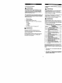
Select the appropriate extension cord gauge and length
using the chart below.
MINIMUM GAUGE (AWG) EXTENSION CORDS
(120 Volt use only)
Ampere Rating
Total length in feet
Not
More Than
More Than
25'
50'
100'
150'
0
6
18
16
16
14
6
10
18
16
14
12
10
p
12
16
16
14
12
12
16
14
12
NotApplicable
IA WARNINGI
Keep the extension cord clear of the working area.
Position the cord so it will not get caught on the
workpiece, tools or any other obstructions while you
are working with the power tool.
AVAILABLE
ACCESSORIES
IA WARNINGJ
Use only accessories recommended for this cutting
tool. Follow instructions that accompany accessories.
Use of improper accessories may cause injury to the
operator or damage to the cutting tool.
Visit your Sears Hardware Department or see the Sears
Power and Hand Tool Catalog for an assortment of
accessories recommended for use with this cutting tool:
•
•
•
•
•
Flex Drive
Rip Guide
1/8"Cutting Bits
1/8"Hobby Rotary Tool Accessories
>. Cutters
> Polishers
Sanders
Grinders
Most ¼" Shank Router Bits
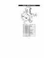
UNPACKING AND CHECKING
[,_,
CARTON CONTENTS
WARNING]
If any part is missing or damaged, do not plug the
cutting tool into the power source until the missing
damaged part is replaced and assembly is complet,
Carefully unpack the cutting tool and all its components
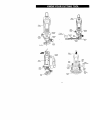
Compare against the "Cutting Tool Components" chart
below.
NOTE: See Page 7 for illustration of components.
I_,
WARNING
I
To avoid fire or toxic reaction, never use gasoline,
naphtha, acetone, lacquer thinner or similar highly
volatile solvents to clean the cutting toot.
CUTTING
KEY
_
TOOL
COMPONENTS
DESCRIPTION
Inside Carrying Case
icuoo,
B
IA WARNINGI
Use only accessories designed for this cutting tool to
avoid severe injury or tool damage.
i
Do not use any accessory unless you have completely
read the instructions or Owner's Manual for that
accessory.
I
J
K
L
Precision
withAttachment
Sole Plate
Freehand Handle
Sole Plate
Circle Cutter Attachment
Circle Cutter Installation Adapter
Plunge Router Base Attachment
Carryin 9 Case
Collet Wrench
Collet Wrench Holder
Front Lid Storage Compartment
I 1/8" Collet Sleeve
I 1/4" Collet Sleeve
Lateral Style Drywall Cutter
Wood / Past c / F berg ass Cutter
I
I
11
i
1
1
1
1
NOTE: The two most commonly used cutters are
included with this tool (items K & L). It is important
that you usa the correct cutter to ensure the most
efficient cutting action.
•
Use cutter "K" with the coarser spiral for cuttin
drywall.
•
Use the general purpose cutter "L" with the fin_
spiral for cutting materials such as wood, plasti
and fiberglass.
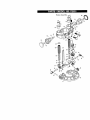
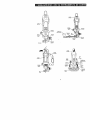
-K
E
Motor
Housing
Motor
Housing
Quick
Mounting
Bracket
Lever
MounUng
Bracket
Quick
Circle
Cutting
Adjus_ng
Knob
Lever
Disc
Moungng
Inse_
Locking
Knob
Motor
Handle
Housing
Depth
Stop
Rod
Motor
Housing
_!
Precision
Height
Adjus_ng Knobs
t
Lockin
Lever
Lockinl
Knob
Plunge
Action
Tu_et
Bevel
Sole _
Plate
Router
Base
Adjusting
Lock
IA WARNINGI
Remove the plug from the power source before
assembly, changing accessories or cutters and
making adjustments. This safety action will help
prevent accidental starting of the tool which could
result in serious injury.
INSTALLING
4.
CUTTING
BITS - Cont'd
Insert new cutting bit (4) into the collet.
I,A WARNING
I
Insertthe bitallthe way intothe colletand then
pullitback between 1/16"
and 11s",
This createsan
airspace between the motor shaftand the bitto
help prevent overheating the bit.
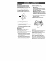
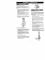
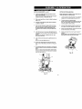
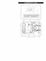
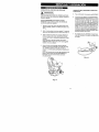
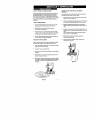
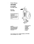
ON / OFF & SPEED CONTROL SWITCHES
This cutting tool is equipped with a sliding ON / OFF
switch (1) located on the side of the tool and a speed
control switch (2) located on top of the tool (see Fig. 1).
Before tightening the collet on the bit, make sure
the flutes (spiral portion) of the bit are completely
visible outside the collet. Clamping the collet on
the bit flutes will result in broken bits and possible
injury.
When bit is properly placed in the collet, depress the
shaft locking button and turn the collet nut clockwise
by hand as far as possible.
6.
Securely tighten collet nut using the wrench.
Fig. 1
1.
To turn the tool ON, slide the switch (1) up.
2,
To turn the tool OFF, slide the switch down.
3.
To set speed to high speed, slide speed control switch
(2) away from the ON / OFF switch.
4.
To set the speed control switch to low speed, slide the
speed control switch (2) toward the ON / OFF switch.
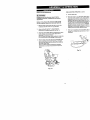
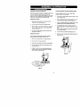
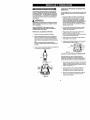
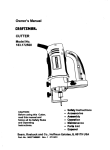
INSTALLING
3
Fig. 2
CUTTING BITS
I,A WARNING I
WORK LIGHTS
Cutting bit and router bit cutting surfaces
extremely sharp. Handle with caution.
are
To insert a cutting bit, use the collet wrench which is in the
wrench holder attached to the power cord.
Depress the shaft
collet lock nut (2)
the locking button
shaft from turning
2
locking button (1) and rotate the
clockwise with the other hand until
drops into place, preventing the
(see Fig. 2).
2.
While continuing to hold the shaft locking button IN,
use the collet wrench (3) to turn the collet nut counter
clockwise. Loosen the collet nut two or three turns.
3.
Remove bit if one is already installed in the tool.
The motor LInit has two built-in work lights (5) (see Fig. 2).
These work lights automatically light up when the motor
switch is turned ON. Patterns or drawings in the immediate vicinity of the bit will be illuminated for better
visibility and improved cutting accuracy.
SELECT APPROPRIATE
MOTOR SPEED
Selecting the appropriate motor speed will ensure
smoother, more efficient cutting action. Choose LOW
speed for grinding, cutting plastics, polishing and when
using wire or bristle brushes. Choose HIGH speed when
cutting wood, using cut-off wheels and to reduce "chatter"
that may develop when cutting some materials at LOW
speed.
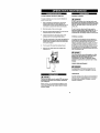
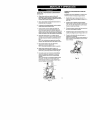
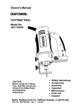
CHANGING
INSTALLING
COLLET INSERT
FREEHAND SOLE PLATE - cont'd
Slide freehand sole plate mounting bracket (1) on"
the bottom of motor housing (2) until the slot in th
bracket (3) lines up with the shaft locking button /
the motor housing,
NOTE: The mounting bracket must be pushed on
the motor housing as far as it will go.
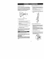
The cutting bits for this tool are locked into place with a
collet nut (1) and collet (see Fig. 3). The tool is assembled
at the factory with NO collet installed. Both the 118"and ¼"
collets can be found in the carrying case front lid storage
compartment. The 1/8" collet (2) is used for holding hobby
tool accessory bits. The ¼" collet (3) is supplied for
holding SMALL router bits with a ¼" shank.
Lock the sole plate to the motor housing by snapr
the quick locking lever (5) firmly against the mote
housing.
3
!
2
4
Fig.
2
1
3
,3
To change from one collet s_e to the other:
5
1.
Remove bit from the tool.
2.
Continue turning the collet nut counter clockwise
it can be removed from the motor shaft (4).
3.
Pull the collet out of the motor shaft and replace it with
the other one.
NOTE: Each collet is the same on both ends, so either
end can be inserted into the motor shaft.
until
4.
Re-install the collet nut and slightly tighten it by hand.
5.
Install the new bit as outlined in INSTALLING
CUTTING BITS on Page 9.
Fig. 4
ADJUSTING
FREEHAND SOLE PLATE
Adjust freehand sole plate depth by loosening th,
depth gauge locking knob (6) and rotating the
adjusting knob (7) to move the sole plate in or eL
required (see Fig. 5).
NOTE: Set the depth gauge so the cutting bit
protrudes beyond the sole plate 1/8"more than tt_
thickness of the material being cut. For example
you are cutting s/s" drywall, the bit should protru¢
beyond the sole plate.
NOTE: Tightening the collet nut without a bit in the collet
will cause the collet hole to become smaller and make
installing bits difficult. When storing the tool with no bit
installed, leave collet nut loose,
INSTALLING
L--1
FREEHAND SOLE PLATE
The freehand sole plate is designed for basic freehand
cutting with the cutting bit. It is ideally suited for cutting
electrical outlet holes in dr/wall.
2.
Securely tighten depth gauge knob.
3.
Before starting to cut you should re-check bit der
Make sure sole plate is at right angles to the bi!
securely tightened. Re-check the collet to make the bit is securely fastened.
IA WARNINGI
Do NOT use the freehand sole plate with router bits.
Limited control with this accessory could cause you
to loose control and inc_ase the chance of serious
injury.
Fig. 5
10
PRACTICE CUTS USING FREEHAND SOLE PLATE
IA WA"NING
I
Have you read "POWER TOOL SAFETY",
"cu'n'ING
TOOL SAFETY" and "ELECTRICAL
SAFETY" on pages 3, 4 and 5 of this Manual? If
not, please do it now before you operate this
cutting tool. Your safety depends on itl
6.
Set the speed control switch to the appropriate speed.
7.
Turn the switch ON.
When the motor is up to full speed, slowly tip the tool
to an upright position, letting the bit cut into the
workpiece (see Fig. 7). Once the tool has reached the
upright position and the bit has cut through the
workpiece, slowly move the tool in a clockwise
direction using slow steady pressure to make the cut.
NOTE: Except for cutting around outlet boxes in
drywall, always cut in a clockwise direction.
Every time you use the cutting tool you should
verify the following:
1. Cutting tool cord is not damaged.
2. Bit is correct type for the material being cut.
3. Bit is sharp, in good condition, properly
installed and securely tightened.
4. Safety glasses and dust mask are being worn.
When cut is complete, turn the tool OFF, wait until it
comes to a complete stop and remove it from the
workpiece.
Failure to adhere to these safety rules can greatly
increase your chances of injury.
PRACTICE
CUTS USING FREEHAND
SOLE PLATE
Before attempting to work on an actual project, take the
time to make a few practice cuts with your cutting tool
Use some scraps of material that are the same material as
used in your actual project.
1.
Draw a pattern similar to your first project on a scrap
piece of material.
2.
Install freehand sole plate as shown in Fig. 4.
3.
Install cutting bit in the collet as shown in Fig. 2.
4.
Adjust depth of freehand sole plate as shown in Fig. 5.
5.
Rest the edge of the sole plate on the workpiece with
the bit at an angle of about 45= (see Fig. 6).
NOTE: DO NOT let the bit contact the workpiece until
switch is turned ON and the tool is up to full speed.
Fig. 7
I_,
DANGER
I
Do not attempt cutting around outlet boxes in drywall
until:
1. All electricity in the vicinity of electric wires has
been disconnected by either turning the breaker
OFF or removing the fuses.
2.
You have read the instructions on the following
page entitled "CUTTING OUTLET OPENINGS IN
DRYWALL".
I_ WARNING I
CUTTING TIP,S
Before turningthe toolswitch ON, make sure you
hold the toolfirmlywith both hands, Starting
torque willcause the toolto twist,
The rotating cutting action of the bit will cause a slight pull
to the left when cutting. Natural variations in the structure
of wood will cause the bit to "wander'. This tendency will
be magnified when applying too much pressure to the bit.
Slower cutting gives you better control. Excessive
pressure or fast cutting will increase bit temperature and
shorten the life of the bit.
When cutting a hole in a vertical surface, avoid ending the
cut at the bottom of the hole. Always start and end the cut
at the "top" so the cut-out part will not drop onto the
rotating bit. Always turn the tool OFF before removing it
from the workpiece.
Fig. 6
11
CUTTING
OUTLET OPENINGS
IA DANGER
cu'n'ING
IN DRYWALL
6.
Move the bit slowly to the right until you feel and
the bit contacting the inside of the box.
7.
Pull the bit out far enough to slip it over the edge
the box. Once the bit is outside the box, push it b_
to full depth beside the outside edge of the box.
I
Do not attempt to use this tool to make out-outs
around any fixture or opening which has live electrical
wires or on any wall which may have electrical wiring
behind it. If a live wire is contacted, the bit could
conduct the electric current to the tool, creating an
electrocution hazard for the operator. Turn OFF
breakers or remove fuses to disconnect
the electric
circuit in the area of work, Always hold the tool by its
insulated housing when working in areas where there
is a possibility of contacting electric wires. Always
wear eye protection when operating this tool.
OUTLET OPENINGS IN DRYWALL - con_'
Move the tool upward while applying slight pressL
toward the center of the box. When you feel the b
reach the top right hand corner of the box, move t
tool to the teft while applying slight pressure
downward toward the center of the box,
Continue moving the tool around the box in a cou,
clockwise direction while maintaining slight pressu
toward the center of the box. When the box cut-o_
complete. Turn the tool OFF and remove it from t,_
cut-out.
Before installing drywall, push the electrical wires to
the back of the box as far as possible so they will not
be cut by the bit when cutting the opening,
Before fastening the drywall sheet over the electrical
box, mark the sheet as close as possible to the center
of the box opening. Mark should be on the side of the
drywall facing you.
10. Completed electrical box cut-out will be accuratel_
neatly cut (see Fig. 9).
When fastening the drywall in place, do not plaee nails
or screws closer than 12" from the box. This will
prevent the drywall from becoming deformed under
pressure.
4.
Insert cutting bit and install freehand sole plate as
outlined on Pages 9 & 10 of this Owner's Manual.
Adjust depth of cut so the bit will protrude 1/8"beyond
the thickness of the drywall.
Hold the tool firmly with both hands and turn it ON.
Plunge the bit through the drywall at the mark
indicating the center of the box. See Fig. 8 for cutting
pattern.
Fig. 9
NOTE: Always move the cutting bit in a counter
clockwise direction around the outlet box. The natura
tendency of the cutting bit to move to the left will mak_
easier to cut close to the box.
Fig. 8
12
ADJUSTING
•"lr_g.l =15"
INSTALLING
FREEHAND SOLE PLATE - Cont'd
PRECISION HANDLE
The precision handle is designed for use when precision
control over the tool movement is desired. The
comfortable handle can be used with either the right or left
hand.
9
v
8
Fig. 11
Slide precision handle mounting bracket (1) onto the
bottom of motor housing (2) until the slot under the
handle (3) lines up with the shaft locking button (4) in
the motor housing (see Fig. 10).
NOTES:
a) The mounting bracket must be pushed onto the
motor housing as far as it will go.
b) The shaft locking button (5) can now be activated
by your thumb while holding on to the precision
handle
INSTALLING
The circle cutter accessory is ideal for precision cutting of
circles. This cimle cutter can be attached to either the
freehand sole plate or the precision handle sole plate. For
purposes of illustration, the circle cutter is shown with the
freehand sole plate,
Lock the precision handle to the motor housing by
snapping the quick locking lever (6) firmly against the
motor housing.
6
1.
Install freehand sole plate on the tool as illustrated on
Page 10 of this Owner's Manual.
2.
Insert the externally threaded circle cutter mounting
insert (1) into the bottom of the sole plate (2) (see
Fig. 12).
NOTE: Make sure the molded "D" in the mounting
insert is inserted into the matching "D" in the sole
plate.
Place circle cutter mounting hole (3) over the
externally threaded circle cutter mounting insert.
NOTE: Make sure pointed pivot pin (4) is pointing
away from the tool.
4
Screw the internally threaded circle cutter mounting
disc (6) onto the externally threaded circle cutter
mounting insert and hand tighten.
NOTE: Do not over tighten the circle cutter mounting
plastic parts. Hand tighten only.
5
Fig. 10
ADJUSTING
CIRCLE CUTTER
FREEHAND SOLE PLATE
Adjust the circle cutting radius by loosening pivot point
knob (5), sliding it to the correct circle radius and retightening in the desired location.
NOTE: Check circle cutter radius setting by measuring
from the pivot point to the outside of the cutting bit.
Adjust precision handle sole plate depth by loosening
the depth gauge locking knob (7) and rotating the
adjusting knob (8) to move the sole plate (9) in or out
as required (see Fig. 11).
NOTE: Set the depth gauge so the cutting bit
protrudes beyond the sole plate 1/8"more than the
thickness of the material being cut. For example, if
you are cutting 3/4" pine, the bit should protrude 7/8"
beyond the sole plate.
2.
Securely tighten depth gauge knob.
3.
Before starting to cut you should re-check bit depth,
make sure sole plate is at right angles to the bit and
securely tightened. Re-check the coltet to make sure
the bit is securely fastened.
-2
"_"3
Fig. 12
13
I
I
ll:ll!llltlli/l_
CIRCLE CURER
III
OPERATION
CIRCLE CUTTER OPERATION
5.
[_
- cont'd
Turn the switch ON.
WARNING]
Unplug the tool from the power source before
changing accessories, changing bite and making
adjustments.
When the motor is up to full speed, slowly 1
and circle cutter assembly to an upright pc
letting the bit cut into the workpiece (see F
careful to keep the pivot point located at tt"
the circle to be cut. Once the tool has reac
upright position and the bit has cut througt
workpiece, slowly move the tool in a clock
direction using slow steady pressure to ms
Continue to cut the circle, keeping the tool
rotating around the circle cutter pivot point
Before turning the tool ON, check to make sure bit
and all accessory fasteners are securely tightened.
1.
Mark the center of the circle you wish to cut on the
workpiece and drill a 6 mm or isle4" pilot hole.
2.
Adjust cutting bit depth to lie" longer than the
thickness of the material being cut (see Fig. 5).
3.
Adjust the circle cutting radius by loosening pivot point
knob, sliding it to the correct circle radius and retightening in the desired location.
NOTE: Check circle cutter radius setting by measuring
from the pivot point to the outside of the spiral bit.
4.
Rest the edge of the sole plate on the workpi_ce with
the bit at an angle of about 45 °. (see Fig. 13). Insert
the circle cutter pivot point-into the pilot hole ddlled at
the center of the circle.
NOTE: DO NOT let the bit contact the workpiece
before switch is turned ON and the tool is up to full
speed.
When cut is complete, turn the tool OFF, v
comes to a complete stop and remove it fr
workpiece.
\
Fig. 14
Fig, 13
14
• ImB = I_Ul_,[€_:41_ellJ.l_
KY-,_::II
The router accessory converts your cutting tool into a
small hobby plunge router that is capable of handling
sman ¼" shank router bits as well as the spiral cutting bit.
The tilting base is ideal for bevel cutting. The plunge
feature allows you to pro-set up to three different cutting
depths.
[,_
WARNING
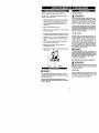
SETTING ROUTER DEPTH FOR SINGLE DEPTH ONLY
Depth of cutting is controlled by sliding the router base up
and down on the guide rods and locking it in place.
Raise plunge router depth stop rod by turningthe
lower depth stop lock nut (1) counter clockwise until it
is positioned at the bottom of the depth stop rod (2)
(see Fig. 16). Push depth stop quick release button (3)
and raise the depth stop rod to its maximum height
and then release the button.
I
Unplug the tool from the power source before
changing accessories, changing bits and making
adjustments.
Before turning the tool ON, check to make sure the bit
and all accessory fasteners are securely tightened.
2.
Rotate plunge action turret (4) untilthe shortest stop
screw is under the depth stop rod (2).
3.
Loosen both height adjusting knobs (5) by turning
them counter clockwise.
NOTE: Only loosen height adjusting knobs enough to
release the tension on the guide rods (6).
4,
Slide router base (7) up or down to obtain the desired
depth of cut.
5.
Re-tighten both height adjusting knobs when the
desired cut depth is reached.
ROUTER ACCESSORY INSTALLATION
1.
Remove any accessory already installed on the tool.
2.
Slide router accessory mounting bracket (1) onto the
bottom of motor housing (2) until the mounting hole (3)
lines up with the hole in the mounting bracket (see Fig.
15).
NOTE: The raised hole in the mounting bracket will
slide over the motor shaft locking button.
3.
Re-insert accessory locking knob (4) into the motor
housing and securely tighten.
Fig.
16
SETrlNG PLUNGEDEPTH
Up to three different plunge depths can be pre-set by
using the depth stop rod and plunge action turret. This
provides for quick changes between depth settings.
Fig. 15
15
1.
Turn lower depth stop lock nut (1) to the bottom of
depth stop rod and upper depth stop lock nut (2) to
the top of depth stop rod (3) (see Fig. 17),
2.
Push depth stop quick release button (4) and raise the
depth stop rod to its maximum height and then
release the button,
3.
Rotate plunge action turret (5) until the shortest stop
screw is under the depth stop rod.
SETTING
PLUNGE
DEPTH
- cont'd
4,
5.
SETTING ROUTER BASE BEVEL
Loosen both height adjusting knobs (6) by tuming
them counter clockwise.
NOTE: Only loosen height adjusting knobs enough to
release the tension on the guide rods (7).
Bevel cutting with the cutting bit can be done with the
router base tilted to the desired angle.
Slide router base (8) up or down to obtain the desired
depth of cut.
I.
Loosen both bevel adjusting locks (1) by pulling th_
outward from the router base (2) (see Fig. 18).
2.
Tilt router base to the desired angle.
NOTE: There are detents for locking the router ba_
at O°, 15°, 300 and 45 °. These are the four most
common angles for bevel cutting.
6.
Re-tighten height adjusting knobs when the desired
cut depth is reached.
7.
Push the depth stop quick release button and lower
depth stop rod until it contacts the turret stop screw
(9). After releasing the quick release button, finer
adjustments can be made by tuming the depth stop
rod.
3.
Lock both bevel adjusting locks by pushing them
firmly back into position against the router base.
4.
Check bevel angle between router base and router
to ensure they are at correct angle.
8,
Lock both lhe lower (1) and upper (2) depth stop lock
nuts against the router body to lock the depth stop rod
in place.
NOTE: Do not use pliers to tighten lock nuts. T_um
lock nuts by hand only.
5.
Check router depth of cut and re-set the depth if
required.
NOTE: Depth of cut will usually have to be increas,
after tilting the router base for bevel cutting.
9.
Lock shortest turret stop screw by tightening lock nut
(10).
NOTE: Do not over tighten lock nut.
10. Loosen both height adjusting knobs just enough to
allow rouler to freely slide up and down on the guide
rods.
11. Two additional depths can be pre-set in a similar way
setting the other two turret stop screws to the desired
depth.
NOTE: To select pre-set plunge depth, simply rotate
the turret until the correct turret stop screw is aligned
under the depth stop rod.
'"2
Fig. 18
1
9
Fig. 17
16
FREEHAND
CUTTING
AND
CUTTING STRAIGHT LINE WITH STRAIGHT EDGE
ROUTING
When the router base accessory is installed on the cutting
tool, it will function as a small router to be used for
freehand cutting of irregular shaped patterns. You can cut
patterns out of the workpiece with the cutting bit or route
patterns into the workpiece with small router bits,
To cut a straight line, you can use a straight edge
template to guide the router base,
1.
Draw a line on the workpiece where you wish to m
the cut (see Fig. 20),
FREEHAND CUTTING
2.
Draw a parallel second line approximately 21/8"ba(
into the workpiece (away from the cutting line).
1. Adjust the cutting bit depth to 1Is"longer than the
thickness of the material being cut.
3.
Clamp the straight edge onto the larger portion of 1
workpiece that is to be clamped while cutting.
4.
Place the flat side of the router base against the
straight edge with the bit near the start of the cuttin
line.
NOTE: Check bit location to ensure cut will be mad
in the correct location.
2.
Turn the switch ON while firmly holding the tool.
3.
When starting the cut inside the workpiece, place the
bit at an angle to allow the bit to cut its way into the
workpiece (see Fig. 6).
4,
Use the two height adjusting knobs to guide the bit
through the workpiece,
5. Turn the switch ON while firmly holding the tool.
FREEHAND ROUTING
6. Slide the router plate against the straight edge whil
making the cut.
Use the router base with small router bits to perform
various freehand routing projects (see Fig. 19).
1,
Remove 1/8"collet and insert '/," collet (see Fig, 3).
2.
Install router bit and securely tighten.
3. Adjust router base height to the correct routing depth.
4.
Turn the switch ON making sure the router bit is not
touching anything.
5.
Holding the tool by the two height adjusting knobs,
carefully lower the bit onto the workpiece and guide
the bit around the desired pattern.
Fig. 20
Fig. 19
17
",lllll_[€'l=
I_..[e]lll:l'|
:T_,_."]
CUTTING CURVED LINE WITH A TEMPLATE
EXTERNAL CLEANING
To cut a curved line, you can use a curved template to
guide the router base.
I_
2.
3.
4.
WARNING
I
Make a template from hardboard or other similar
material to the shape you require (see Fig. 21).
NOTE: Radius of curve must be greater than 2½" for
router base to properly follow the curved template.
DO NOT use solvents when cleaning plastic pants,
Most plastics are susceptible to damage from variou
types of commercial solvents and may be damaged !
their use. Use clean cloth to remove dirt, dust. oil,
grease, etc.
Mark the location of the cut to be made,
Do not at any time
petroleum-based
come in contact
Mark the workpiece approximately 27/16"back into the
workpiece (away from the cutting line),
chemicals
Clamp the template onto the larger portion of the
workpiece that is to be clamped while cutting,
5.
Place the curved portion of the muter base against the
template with the bit near the start of the cutting line.
NOTE: Check bit location to ensure cut will be made
in the correct location.
6.
Turn the switch ON while firmly holding the tool.
7.
Slide the router plate against the template while
making the cut.
allow
brake
fluids,
gasoline,
products,
penetrating
oils, etc.
with plastic parts. They contain
that can damage,
weaken
or destroy
to
plas
INTERNAL CLEANING
It has been found that electric tools are subjected to
accelerated wear and possible premature failure when
they are used on fiberglass boats and sports cars,
wallboard, spackling compounds or plaster. The chips
gdndings from these materials are highly abrasive to
electdc tool parts such as bearings, brushes, cemmuta:
etc. During any use on these materials it is extremely
important that the tool is cleaned frequently by blowing
with a compressed air jet,
I_.
DANGER
I
It is critical that you wear safety goggles or safety
glasses with side shields and a dust mask while
blowing dust out of the cutting tool with a
compressed air jet. Failure to take these safety
precautions could result in permanent eye or lung
damage.
POWER CORD MAINTENANCE
1,,_
WARNING]
To avoid shock or fire hazard, replace the cord
Immediately if it is worn or damaged in any way.
Fig. 21
I
I_.
LUBRICATION
II
DANGER
All of the bearings in this cutting tool are lubricated wit!
sufficient amount of high grade lubricant for the life of t
unit under normal conditions. Therefore, no further
lubrication is required.
[
For your own safety, turn the switch OFF and remove
the plug from the power source before maintaining
your cutting tool,
When servicing, use only identical Craftsman parts.
Use of any other part may create a hazard or cause
product damage.
18
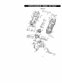
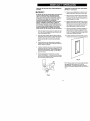
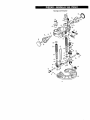
Main Unit
C
19
I_
WARNING}
When servicing use only CRAFTSMAN replacement
damage to your Cutting Tool.
parts. Use of any other parts may create a HAZARD or ca
Any attempt to repair or replace electrical parts on this Cutting Tool may create a hazard unless repair is
performed by a qualified technician. Repair service is available by contacting your nearest Sears Service Cm
Always order by PART NUMBER,
not by key number.
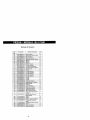
Main Unit
Key #
1
2
3
5
10
11
12
13
14
15
17
18
19
22
23
24
25
28
29
30
31
34
35
36
37
38
39
40
41
42
Part #
01AR-000032-00
01AR-000035-00
01AT-000014-A0
01AT-000031-00
02AE-000060-00
02AE-000061-00
02AK-000022-00
02AH-000088-00
02AH-000089-00
02AH-000112-00
02AS-000199-A0
02AS-000201-A0
02AS-000260-00
02AW-000055-00
03AA-000279-00
03AC-00001 l-F0
03AC-000043-00
03AD-000009-A0
03AD-000040-00
03AD-000074-00
03AD-000075-00
03AM-000104-00
03AM-000105-00
03AP-000073-00
03AP-000076-00
03AR-000013-A0
03AR-000015-D0
03AR-000109-A0
03AS-000135-00
03AS-000140-00
Part Name
Beating Sleeve
Switch presser
Bushing tube
Bushing tube
Front beadng
Rear beadng
Rivet
Brush spdng
Spindle spring
Hanger
Case screw
Screw
Machine screw
Retaining dng
Transformer
Capacity
Capacity
Diode
Diac
LED
Tdac
Stator
Rotor
PCB
PCB
Resistor
Resistor
Resistor
Micro switch
Switch
Qty
1
1
2
2
1
1
4
2
1
1
8
3
1
1
1
1
1
4
1
2
1
1
1
1
1
1
1
3
1
1
Key #
44
48
49
50
53
55
56
59
62
62,
63
67
70
71
72
*
73
74
78
77
79
80
81
82
83
84
85
87
91
92
20
Part #
03AT-000033-00
03AT-000040-00
03AT-000046-00
03AW-000131-00
03AY-000020-00
03AY-000073-00
03AY-000074-00
04AP-000068-00
2203-MA0003-00
2203-MA0004-00
2203-MA0007-00
2207-MA0003-00
2213-MA0002-00
2213-MA0005-00
2213-MA0006-00
2213-SAM001-00
2213-MA0011-00
2213-MA0012-00
2213-MA0014-00
2213-MA0015-00
2203-PA0008-00
2207-PA0007-00
2213-PA0022-00
2213-PA0023-00
2213-PA0024-00
2213-PA0025-00
2;213-PA0026-00
2213-PA0028-00
9866-PA0004-00
9920-PA0011-00
Part Name
Terminal block
Terminal (female)
Carbon brush
Power cord
Wire
Wire
Wire
Fibra
1/4" coilet
1/8" collet
Lock plate
Spindle lock
Conductor
Chuck cap
Spanner
Brush assembly
Metal conductor
Brush case
Wire cover
Stop plate
Spanner belt
Screw lock B
Bottom cabinet
Top cabinet
Switch cover
Lock button
Cover
2P-Switch
Press plate
Cord Sleeve
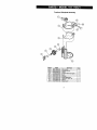
Freehand
Key #
201
202
203
208
211
212
213
214
215
216
Part #
02AF-000041-10
02AF-000076-00
02AS-000287-00
2213-MA0010-00
2213-PA0010-00
2213-PA0011-00
2213-PA0012-00
2213-PA0013-00
2213-PA0014-00
2213-PA0015-00
Soleplate
Assembly
Part Name
Fixing shaft
Release lock pin
Screw
Freecut metal round guide
Lock
Fixbase
Plastic guide base
Adjustment Gear 15"1"
Sleeve
Screw lock F
21
Qty
1
1
1
1
1
1
1
1
'1
1
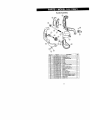
Handle Assembly
Key #
301
302
304
305
306
307
310
312
321
323
324
325
326
327
328
329
330
331
332
Part #
02AF-000041-10
02AF-000076-00
02AH-000106-00
02A8-000148-00
02AS-000287-00
02AS-000288-00
02AW-000067-00
2213-MA0013-00
2213-PA0010-00
2213-PA0012-00
2213-PA0013-00
22t3-PA0014-00
2213-PA0015-00
2213-PA0016-00
2213-PA0017-00
2213-PA0018-00
2213-PA0019-00
2213-PA0020-00
2213-PA0021-00
Part Name
Fixing shaft
[
Release lock pin
Compressive spdng
Screw
t
Screw
Screw
Washer
S-round guide holder
Lock
Plastic guide base
Adjustment Gear 15T
Sleeve
Screw lock F
Anx right handle
Anx left handle
Anx handle softgrip (outside)
Anx handle softgrip (inside)
Simple lock
I Shaft F5-5
22
Qt),l
1
1
2
1
3
1
1
1
1
1
1
1
1
1
1
1
1
1
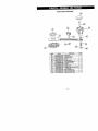
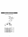
Circle Cutter Assembly
Key #
401
402
403
404
405
410
4!0
411
412
415
416
417
418
419
Part #
02AN-000017-00
02AN-000018-00
02AS-000258-00
02AS-000272-00
02AW-000022-00
2206-MA0001-.00
2206-MA0005-.00
2206-MA0002-00
2206-MA0003-00
2206-PA0001-00
2206-PA0003-00
2206-PA0004-00
2213-PA0007-00
2213-PA0008-00
I
Part Name
Square nut
Hexagon thin nut
Machine screw
Screw
Spring washer
Circular arm (metric)
Circular arm (inch)
Washer
Handle bush
'
Distance lock with center pin
Locking base
Round guide mount
Handle cup-like base
Handle cup-like cover
23
Qty
1
1
1
1
1
1
1
1
1
1
1
1
1
1
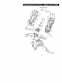
Router Assembly
%
24
Router Assembly
Key #
101
102
103
104
105
107
108
109
111
112
113
114
1t5
117
1t8
119
120
121
122
123
124
128
129
131
133
134
138
139
151
152
153
154
155
156
157
158
159
164
165
166
Part #
02AF-000041-10
02AF-000077-00
02AF-000078-00
02AG-000145-00
02AJ-000017-00
02AH-000107-00
02AH-000108-00
02AH-000109-00
02AN-000001-A0
02AN-000013-00
02AN-000019-00
02AN-000024-00
02AQ-000001-A0
02AS-000020-A0
02AS-000048-A0
02AS-000276-00
02AS-000258-00
02AS-000260-00
02AS-000290-00
02AS-000291-00
02AS-000292-00
0_AW-000068-00
02AW-000070-00
2213-MA0001-00
2213-MA0003-00
2213-MA0004-00
2213-MA0007-00
2213-MA0008-00
2213-PA0001-00
2213-PA0002-00
2213-PA0003-00
2213-PA0004-00
2213-PA0005-00
2213-PA0006-00
2213-PA0007-00
2213-PA0008-00
2213-PA0009-00
2205-PA0004-00
2205-PA0007-00
2207-PA0007-00
Part Name
Fixing shaft
Base release lock pin
Height rod
Guide bush
Router tile base
Spring
Spring
Spdn9
Screw nut
Square nut
M4 fixing nut
Hexagon thin nut
Steel ball
Screw
Machine screw
Base screw
Machine screw
Machine screw
Screw
Screw
Screw
Wave washer
External retaining rings
Guide rod
Knock head
Index guide
Washer plate 1
Washer plate 2
Router fix base
Router movable base
Router quick height lock
Memory post dial
Lock
Bellow
Handle cup-like base
Handle cup-like cover
Height adjust knob
Lens
Locking disc
Screw lock B
Qty
2
2
1
2
1
2
2
1
5
2
3
I
1
1
3
6
2
1
1
1
1
1
2
2
2
1
2
2
1
1
1
1
2
2
r
2
2
2
1
2
1
For repair of major brand appliances in your own home...
no matter who made it, no matter who sold it!
1-800-4-MY-HOME
®
Anytime, day or night
(U.S.A. and Canada)
(1-800-469-4663)
......................................
.w..W_N_
.sears.corn
...................
_:sears:ca
......................
For repair of carry-in products like vacuums, lawn equipment,
and electronics, call for the location of your nearest
Sears Parts and Repair Center.
1-800-488-1222
Anytime, day or night (U.S.A. only)
www.sears.com
Forthe replacement parts, accessories and owner'smanuals
thatyou need to do-it-yourself,call Sears PartsDirectSM!
1-800-366-PART
6 am - 11p m CST,7 daysa week
(1-800-366-7278)
(U,S.A. only)
www.sears.com/partsdirect
To purchase or inquire about a Sears Service Agreement
or Sears Maintenance Agreement:
1-800-827-6655
(U.S.A.)
1-800-361-6665
7 a.m. - 5 p.m. CST, Mon. - Sat.
9 a.m. - 8 pm. EST, M - F, 4 p.m. Sat.
Para pedir serviciode reparaci6n a
Au Canada pour service en francis:
domicilio, y para ordenar piezas:
1-888.SU-HOGAR sM
(1-888-784-6427)
:
(Canada)
1-8O0-LE-FOYER
Mc
(1-800-533-6937)
www, sears.ca
I
{ HomeCentralUS
1 ' /S
® Registered Trademark I'm Trademark
I sM Service Mark of Seam, Roebuck and Co.
® Mama Registrada I'rU Mama de F_b_ca I sM Marca de Servk:io de Seam, Roeb_JCk and Co.
Mc Marque de commerce I _ Marque d_pos_e de Sears, Roebuck and Co.
_R
® Sears,
Roebud_ and Co.
Manual del propietario
CRAFTSMAN®
HERRAMIENTA
TODO EN UNA
DE CORTE
Modelo No.
183.172521
Aviso
importante
de segurldad
_1_ ADVERTENClA]
Siempre sostenga el cuerpo de
la herramienta con una mano
mientras la use. Nunca use la
herramienta sostenidndola sblo
pot el asa.
ADVERTENClA:
Lea esta manual y siga
todas sus reglas de
seguridad e instrucciones
de operacibn antes de usar
esta herramienta de corte.
• Instrucciones
• Accesorios
de seguridad
• Montaje
• Operacibn
• Mantenimiento
• Lista de piezas
• Castellano
oo
o_
Sears, Roebuck and Co., Hoffman
No, de parte 183172520003
Rev. 3
06127102
Estates,
IL 60179 USA
SECCION
Garantia ........................................
Especificaciones del producto.............
PAGINA
2
2
Seguridad
3
con herramientas
el_ctdcas..
Seguridad
con la herramienta
corte .............
Requisitos
Accesodos
de
de electricidad
y seguridad...
......................................
4
SECCION
Contenido de la caja ........................
Familiadcese con su herramienta de
corte ......
Montaje y operaci6n ........................
Mantenimiento ................................
PAGINA
6, 7
8
9 - 18
18
5
6
Piezas de reparaci6n .......................
Piezas y disponibilidad de servicio ......
19 -25
26
iIV,-'I
GARANTiA
Sears, si asi Io decide,
falla debido a defectos
compra.
COMPLETA
POR UN AI_O
reparar_ y reemplazar_
esta herramienta
de materiales
o de fabricaci6n,
durante
Envie esta herramienta de corte a un Centro
donde la adquiri6 para su reposici6n.
Esta garantia le da ciertos derechos
que cambian de estado en estado.
Sears, Roebuck
legales,
de servicios
adem&s
de corte sin costo alguno si la misma
un aSo contado desde la fecha de su
de Sears
de los cuales
and Co., Dept. 817 WA, Hoffman
para su reparaci6n,
usted
Estates,
puede
o al lugar
en
tener otros derechos
IL 60179
A
ADVERTENCIA
L; erto po vo causaoo por el lijado eldctrico, el aserrado, el molido, perforado y demos actividades de la
construcci6n, contiene productos quimicos que (segt_n el Estado de California) se sabe que causan c:tncer,
defectos congdnitos u otras lesiones al aparato reproductor. Algunos de estos productos quimicos son:
•
El plomo de pinturas con base de plomo.
•
El silice cristalino de los ladrUlos, el cemento y otros productos de albaSileria.
•
El ars_nico y el cromo de la madera tratada quimicamente.
El riesgo al que se somete por exposici6n var|a dependiendo de cu&n frecuentemente
haga este tipo de trabajo.
Para reducir su exposici6n a estos productos quimicos, trabaje en un _rea bien ventilada y use el equipo de
seguridad prescrito, tal como las m_scaras oontra el polvo dtser_adas especialmente para filtrar las particulas
microsc6picas.
Capacidad del motor ..........
Ampedos ........................
2 velocidades (sin carga) ...
120V, 60Hz, CA
5.0 Ampedos
20000 & 30000 RPM
Potencia del motor .....
Peso ........................
314 HP (al m_ximo)
1.7 kg
A ADVE.TE.C,A
]
Use el protector de circuitos adecuado para evitar choques eldctrlcos, el desgo de Incendios o da_ar la herramlenta de corte
Esta herramienta de corte ha sido ensamblada
para trabaJar con 110-120 voltlos. Debs conectarse
a un fusible de retardo o _"
un cortacircultos
de 110-120 voltios/15 amperlos.
Rsemplace
el cable de cordente de inmedlato s| sst_ gastado, cortado o
da_ado de cualquler forma para evitar choques o Incsndlos.
Antes de usar su herramtenta de code, es vital que lea y que comprenda
puede sufdr leslones sedas o da_ar la herramlenta
de code.
estas reglas de seguddad.
Sl no slgue estas reglas
Antes de usar su herramienta de corte es vital que lea y que comprenda estas reglas de seguridad.
Si no sigue estas reglas puede sufrir lesiones serlas o dar_ar la herramienta de corte.
Las buenas pr_cticas de seguridad son ta combinacibn del senUdo
com0n, de estar elerta y de saber cbmo usar su herramienta
el_ctrica. Para evitar errores que le puedan causar lesionea serias,
no conecte su herramienta de code hasta que haya leEdo y
entendido tas siguientes regtas de segurk:iad:
1.
LEA todo y familiarlcese con este Manual del propietario
CONOZCA las aplicacionea, los Ilmites y los pesibtas riesgos
de esta herramienta.
A
uso de accesorios inadecuados puede causarle lesiones y
da_ar la herramienta.
15. RETIRE LAS CLAVlJAS Y LLAVES DE AJUSTE. Fbrmese el
h_bito de vedficar que se hayan retirado las tiaras y las Ilaves
de ajuste de la herramienta antes d_ poneda en posicibnde
"ENCENDIDO'.
16. NUNCA DEJE FUNCIONANDO SOLA UNA HERRAMIENTA.
APAGUE LA HERRAMIENTA. NO descu_de la herramienta
antes de que se detenga pot completo.
ADVERTENClA
Busque este simbolo que identiSca las precauciones de
seguridad importantes. Significa IIPRECAUCI6NI
.
IMANTENGASE ALERTAI ISU SEGURIDAD ESTA EN
JUEGOt
17. NUNCA SE PARE SOBRE LA HERRAMIENTA.
Puede sufrir
lesiones sedas si la herramienta se voitea o si toca la
herramienta de code involuntariamente.
18. NO SE ESTIRE DEMASIADO.
equilibrio en todo momento.
Mantenga un buen sost_n y su
3.
USE LAS GUARDAS y mant6ngalas en buen estado.
4.
NO SE USE EN AMBIENTES PELIGROSOS tales como an
sitios h0medos, mojados ni expuestos a ta Iluvia. Mantenga el
_rea de trabajo bien iluminada.
19. CUIDE BIEN SU HERRAMIENTA.
Mantanga las herrsmientas
afiladas y limpias para un rendimiento m_,s ef'K:azy seguro,
Siga las instrucciones para su lubricacibn y para el cambio de
accesorios.
5.
NO use herrsmlentes el_ctricas en presenc_a de Ilquidos o d"e
gases inflamables.
20.
6.
MANTENGA LIMPIA EL AREA DE TRABAJO. Las _reas y
las mesas de trabajo abarrotadas invitan a los accidentes.
7.
MANTENGASE ALEJADO DE LOS NII_IOS. Todos los
visitantes deben ester a una distancia segura del :_rea de
REVISE QUE NO HAYAN PIEZAS DA_IADAS.
Antes de
seguir usando una herramienta, una guarda u otra parte
datlada, la misma se debe inspecc)onar para vedficar qua
funcione debidamente y que cumpla su funckSn correspondiente.
Verifique la alineacibn de las partes mbviles, el ret_n de las
mismas, su montura y cuelquier otra condicibn que afecte su
funcionamiento seguro. Se deber_, reparar o cambiar toda
guarda u otm parte que est_ dat_ada.
trabajo.
8.
NO FUERCE LA HERRAMIENTA`
La misma harb el trabajo
mejor yen forma m;_ssegura a la velocidad para la que fue
dise_ada.
21.
DISPONGA SU TALLER A PRUEBA DE NII_IOSusando
eandados, interruptores principales o retJrando las Ilaves de
encendido.
9.
USE LA HERRAMIENTA
22.
NO use ta herramienta bajo la influencia de drogas, de alcoho]
o de medicamentos que limiten su habilidad para uear la misma
en forma segura.
ADECUADA.
No fuerce la
herramienta o el accesorio a hacer un trabajo para el coal no
est,_ diser3ada.
10, VISTA LA ROPA ADECUADA` NO use ropa suelta, guantes,
corbatas, aniJlos, brazaletes ni joyes qua puedan engancharse
en las partes mbviles. Se recomienda usar calzado que no
resbale. Use un protector para el cabeilo para retener el pelo
largo.
23.
11.
USE UNA MASCARA O MASCARILLA CONTRA EL POLVO.
Las operaciones de aserrado, code, perforado y lijado
producen polvo peligroso.
24.
12.
DESCONECTE LA HERRAMIENTA DE LA FUENTE DE
CORRIENTE antes de hacerle servicio y cuando cambie los
accesorios tales como las hojas, las brocas, las sierras, etc.
13.
REDUZCA EL RIESGO DEL ENCENDIDO
INVOLUNTARIO.
Verifique que el interruptor est_ en ta posic,;bn"APAGADO"
antes de enchufar ta herramienta a la corriente.
14.
SOLO USE LOS ACCESORIOS RECOMENDAIDOS.
Busque
los accesorios recomendados en et Manual del propietario. El
GUARDE
UTILICE RECOLECTORES
DE POLVO en to posible. El polvo
generado pot ciertea materiales puede ser datlino para su salud
y causar ineandios en ciertos casos. Use siem;xe la
harramienta en un Area bien ventilada con la remocibn de polvo
adecuada.
PROTEJA SIEMPRE LA VISTA. Toda herramienta ei_.ctrica
puede lanzar partlculas extrarlas a
sus ojos Io que los puede dattar
permanentemente. USE SIEMPRE
galas de seguridad (no anteojos)
que cumptan con la norma de
seguridad ANSI Z87,1. Los
anteojos de uso diario sblo tienen lentes que resisten a los
golpes. NO SON galas de seguridad. Sears dispone de galas
de seguddad.
Los anteoJos o galas que no cumplen con la norma ANSI Z87.1
pueden causarte leslonos severea al romperse.
ESTAS INSTRUCClONES
COMO REFERENClA
para operar la herramienta.
[A
AOVERTENClAJ
Para su seguridad, no enchufe su herramienta de
corte ni intente user cualquier accesorio que no est6
ensamblado e instalado complatamente segdn estas
instrucciones, y hasta no haber leido y entendido este
Manual del propietario.
Puede sufrir el riesgo de lesiones serias si no sigue
estas reglas de seguridad.
USE PROTECTORES PARA LA VISTA. Esta
herramienta de alta velocidad barb saltar particulas
de la pieza de trabajo durante su operacibn.
Aseg0rese que sus gafas de seguridad tengan lades
protegidos.
2.
USE UNA MASCARA PARA EL ROSTRO O
CONTRA EL POLVO edemas de galas de seguridad
si la operaci6n de corte o de fresado es polvorienta.
Aseg0rese que su area de trabajo est_ bien ventilada.
3.
PROTEJA SUS OIDOS, en especial durante trabajos
prolongados.
4.
NUNCA USE BROCAS ROMAS O DA_ADAS, Las
brocas dafiadas se pueden romper repentinamenteT
Las brocas romas pueden sobrecargar el motor,
cortar m_s lento y ser dificiles de controlar. Tambien
se pueden recalentar y romper.
5.
VERIFIQUE SIEMPRE QUE LA PIEZA DE
TRABAJO NO TENGA CLAVOS U OBJETOS
EXTRAROS. Si la broca choca contra un clave,
saltar_ a un lade y puede romperse.
6.
NO USE ESTA HERRAMIENTA PARA PERFORAR
AGUJEROS, La misma NO fue disefiada come un
taladro.
7.
DEJE UN ESPACIO BAJO LA PIEZA DE TRABAJO
para que la broca se mueva. Nunca coloque la pieza
de trabajo sobre superficies duras come hormigbn,
etc. La broca puede saltar o romperse cuando toque
otra superficie que no sea la que se estd cortando.
8.
FIJE SIEMPRE EL MEDIDOR
LA PROFUNDIDAD DEBIDA.
con el medidor de profundidad
contra la superficie de trabajo
herramienta.
DE PROFUNDIDAD A
Use la herramJenta
en posici6n plana
para controlar meier la
9.
NUNCA USE LA HERRAMIENTA SIN LA BANCADA,
EL ASA DE PRECISION O LA BASE DE FRESADO
colocados y fijados debidamente.
10. FIJE SIEMPRE LA PIEZA DE TRABAJO CON
ABRAZADERAS PARA MANTENERLA FIRME
MIENTRAS CORTE. E_stodejar_ libres ambas manes
11. NUNCA SOSTENGA LA PIEZA DE TRABAJO COt
UNA MANe mientras opera la herramienta con lae
mane.
12. NUNCA COLOQUE LAS MANES EN EL CAMINO
DE LA SIERRA NI DEBAJO DE LA PIEZA DE
TRABAJO.
13. NUNCA ENCIENDA LA HERRAMIENTA CUANDo
LA BROCA TOQUE LA PIEZA DE TRABAJO. La
broca puede engancharse en la pieza haci_ndole
perder el control
14. SIEMPRE SOSTENGA LA HERRAMIENTA CON
AMBAS MANES CUANDO LA ENCIENDA Y LA
OPERE. El torque del motor al encenderce puede
hacer que la herramienta se retuerza.
15. APAGUE TODOS LOS CORTACIRCUITOS Y
RETIRE TODOS LOS FUSIBLES del _rea de trabaj
cuando haga cortes en las paredes o en _reas ocuJh
16. SOSTENGA SIEMPRE LA HERRAMIENTA PeR
LAS SUPERFICIES AISLADAS DE AGARRE DEL
CUERPO DE LA MISMA cuando exista ta posibilidac
de que la sierra toque cables el_ctricos ocultos o el
cable de la herramienta. El contacto con cables con
cordente har_ que pase corriente a lea partes de
metal expuestas de la herramienta, y le dar_ un
cheque electrico al usuario.
17. CUANDO HAGA ABERTURAS PARA TOMAS DE
CORRIENTE EN PIRCA usando el tomacorriente
come guia, haga siempre el corte en sentido contra
las agujas del refoj. La tendencia natural de la
herramienta a tirar hacia la izquierda causar_ que se
acerque m_s a la toma de corriente, dando un corte
mas precise.
18. NUNCA RECUESTE LA HERRAMIENTA HASTA
QUE LA SIERRA SE HAYA DETENIDO PeR
COMP_LETO. La broca en movimiento puede tocar I_
superficie y descontrolada.
19. NUNCA TOQUE LA BROCA INMEDIATAMENTE
DESPU_S DE USARLA. La broca estar_ muy
caliente para manipulada con las manes
desprotegidas y le quemar_ los dedos.
20. VUELVA A APRETAR SIEMPRE EL MANDRIL DE
PINZA Y TODOS LOS AJUSTES antes de arrancar
la herramienta tras cambiar la broca o un accesorio.
Las brocas y los ajustes flojos pueden hacer que la
herramienta se mueva sorpresivamente, haci_ndole
pettier el control y pudiende causade lesiones per la
broca oal salter ra hen'amienta.
GUARDE ESTAS INSTRUCCIONES COMe REFERENCIA
:! [_] IF±1_VjlI _ _11I[O] mIo] :| Ill
Esta herramienta de corte tiene un aislamiento
protegedo contra choques el_ctdcos.
II ! I _1_.'1_vdI :l_ll Ko}.l ",/:A:!;lof:_l :| I1:_1 o] :11::Q i _ _kl[o] _d
doble para
[A ,ovE.TE.c,,J
Las herramientas de aislamiento doble tienen un
enchufe polarizado (una hoja es mds ancha que la
otra). Este enchufe s61o calza de una forma en el
tomacorrientes polarizado. Si el enchufe no calza
bien en el tomacorrientes, voltde el enchufe. Si a
pesar de Io anterior no calza, contacte a un
electricista calificado para que instale un
tomacorrientes polarizado. No altere el enchufe en
forma alguna. El aislamiento doble elimina la necesidad
de tener un cable de corriente de tres cables con toma a
tierra y un sistema de corriente con toma a tierra.
Evite que su cuerpo toque las superficies con toma a
tierra tales como tuberias, radiadores, estufas y
refrigeradores. Si su cuerpo hace tierra, existe mayor
riesgo de recibir un choque el_ctdco.
No exponga las herramientas eldctricas a la Iluvia o a
la humedad. El agua dentro de una herramienta el_ctrica
aumentar_ el riesgo de recibir un choque el_ctrico.
_
No maltrate el cable. Nunca use el cable para Ilevar la
herramienta ni tire del mismo para desenchufarla.
Mantenga el cable alejado del calor, el aceite, los
objetos afilados y las piezas en movimiento. Reponga
el cable da_ado de inmediato. Los cables daNados
aumentan el riesgo de choques el_ctdcos.
Use un cable de extensi6n para exteriores marcado
con "W-A"o con '_N" cuando opere una herramienta
eldctrica en exteriores. Estos cables estdn clasificados
para usos exteriores y reducen el riesgo de choques
et_ctricos.
Verifique que su cable de extensi6n estd en buen
estado. Cuando use un cable de extensibn, asegt_rese
de que el mismo pueda transmitir la corriente qua requieP_
la herramienta. Un cable de calibre inferior hard qua
caiga e! voltaje de la linea, to que hard qua falte energia y
el mismo se recaliente. La tabla de abajo muestra el
calibre correcto seg6n la Iongitud del cable y su capacidac
nominal en amperios. $i tiene dudas use el cable m_s
grande que le siga. A menor nQmero de calibre, mayor
serd el grosor del cable.
Asegt_rese de que su cable de extensi6n estd bien
cableado yen buen estado. Antes de usado, reponga
todo cable de extensibn dar_ado o haga qua un electricist;
calificado Io repare. Proteja su cable de extensi6n contra
los objetos afilados, el calor excesivo o las dreas
ht_medas o mojadas.
Utilice un circuito eldctrico separado para sus
herramientas eldctricas. Los cables de este circuito
deben set alambres de calibre superior a 14 y el mismo
debe estar protegido con un fusible retardado o con un
cortacircuitos de 15 amperios. Antes de conectar la
herramienta el_ctrica a la fuente de corriente, verifique
qua el interruptor est_ en posici6n de "APAGADO" y qua
la fuente de corriente sea la misma qua se indica en la
placa de datos. Si el motor funciona a un voltaje menor,
puede sufrir da_os.
Repare o reponga los cables de extensi6n da_ados de
inmediato.
Escoja el calibre y la Iongitud adecuados del cable de
extensi6n empleando la tabla de abajo.
CALIBRE MINtMO PAR& CABLES DE EXTENSION (AWG)
(Uso
A
Capacidad
ADVERTENCIA
Asegdrese siempre de que ia toma estd polarizada.
tiene dudas, haga que un electricista calificado la
revise.
Si
M_s de
0
6
10
12
exclusivo
en amperios
No mds de
6
10
12
16
de 12 voltios)
Longitud
25'
18
18
16
14
50'
16
16
16
12
total
en pies
100'
150'
16
14
14
12
14
12
Nose aplica
Mantenga el cable de extensi6n fuera del _rea de
trabajo. Ubique el cable de modo que no se enganche
con la pieza de trabajo, la herramienta ni con
cualquier otro objeto mientras usted est_ usando la
herramienta eldctrica.
ACCESORIOS
DISPONIBLES
I& "°vE"TE"c'AI
DESEMPAQUE
t.A CAJA
_k
Y VERIFICACI(_N
DEL CONTE
ADVERTENCIA]
Use sbto los accesorios recomendados para esta
herramienta de corte. Siga las instrucciones que
vienen con los accesorios. El uso de accesorios
inadecuados puede causarle lesiones al usuario o
dar3ar la herramienta de corte.
Si falta alguna pieza o si la misma est_ da_a¢
conecte la herramienta de corte a la fuente d_
corriente hasta volver a colocar la pieza faltm
da_ada y completar el montaje.
Visite el Departamento de Herramientas de Sears o yea
el Catdlogo de herramientas eldctricas y de mano de
Sears para encontrar el surtido de accesorios sugeddos
para esta herramienta:
Desempaque cuidadosamente la herramienta de
todas sus partes. Comp_relas con la tabla de
"Componentes de la herramienta de corte" de ab
NOTA: Las partes se ilustran en la p_gina 7.
•
Propulsor flexible
Guia para desbastar
Brocas espirales de corte de 1/8"
Accesorios de bricolaje de 1/8" para herramientaa
giratorias
P Sierras
_, Putidores
_. Lijas
Muelas
Casi todas las fresas con v_,stago dell4"
Nunca use gasolina, nafta, acetona, disolvenh
esmaltes u otros solventes altamente voldtile._
limpiar la herramienta de code, con el fin de e
incendios o reacciones t6xicas.
COMPONENTES
A
C
Use s61o los accesorios dise_ados para esta
herramienta de corte, para evitar lesiones serias o
danos a la herramlenta.
DE LA HERRAMIEt
DE CORTE
DESCRIPCION
Interior del estuche portdtil
r Herramienta de corte
Asa de precisibn con bancada
', Accesorio de bancada de manos
librea
I Accesorio para cortes circulares
I Adaptador de instalacibn para cortes
circulares
E
1
D
E
No utilice ningt_n accesorio a menos que haya leido
por completo las instrucciones o el Manual del
propietario de ta! accesorio.
G
H
M
N
J ,
ILK
I
I
I
I
I
Accesorio de base de fresado
Manual del propietado
Estuche port_ltil
Llave del mandril
Soporte de la Ilave del manddl
Compartimiento de la tapa frontal
Mandril depinza de 1/4"
Sierra
pirca de
de corte
Mandril para
de pinza
1/8" lateral
Sierra para madera / pl_stico / fibra
de viddo
NOTA: Esta herramlenta vlene con las dos sier
m_s populares (piezas K y L). Es importante ql
la sierra correcta para obtener la acci6n de col
eficaz.
•
Use la sierra "K" con la espiral m_s basta I
cot-tar pirca.
•
Use la sierra "L" para todo uso, con la espi
flna, para cortar materlates como |a madera
pldstico y la fibra de vidrio.
j_
0
del
motor
Abrazadera
de rnonLaje
Perilia de
rapido
Inser_o de
mont_je
Discode
montaie
Perilta de
s_ec_n
Bancada
Cuerpo
del motor
Asa de
CueR_:_ .___..---del motor
Pedflas para
i altura
recisibn
PaEanca
---
_
Pedlla de
sujecibn
_pido
Bancada
Cierre de
ajuste del
biset
MONTAJE DE BROCAS DE CORTE - Continuaci6n
_
ADVERTENCIA
Retire
el enchufe
montaje,
hacer
cambio
los ajustes.
I
de la fuente
de corriente
de accesorios
Esta
acci6n
antes
o de sierras
de seguridad
ayudard
a evitar el encendido
accidental
herramienta,
que podria
causar
lesiones
INTERRUPTORES
DE ENCENDIDO/APAGADO
CONTROL DE LA VELOCIDAD
Siga pulsando HAClA ADENTRO el bot(_n de cierre
del v:_stago mientras hace girar la tuerca del mandril
de pinza en sentido contra las agujas del reloj con la
Ilave del mandril de pinza (3). Gire 2 o 3 vueltas la
tuerca del mandril de pinza para aflojarlo.
del
y antes
de
le
de la
severas.
Y DE
3.
Si la herramienta
4.
Inserte la broca espiral nueva (4) en el mandril de
pinza.
Esta herramienta de corte viene con un interruptor
deslizante de ENCENDIDO/APAGADO
(1) en uno de sus
lados y un control de velocidad (2) arriba de la
herramienta (vea la figura 1).
tiene una broca ya instalada, retirela.
[,_
ADVERTENClA
J
Inserte toda la broca en el mandril de pinza y
luego s_quela entre 1/16" y 1Is". Esto orea un
espacio vacio entre el v_stago del motor y la
broca qua evita que la misma se recaliente.
Antes de apretar el mandril de pinza sobre la
broca, verifique que se puedan ver todos los
canales de la broca (las partes espiraladas) fuera
del mandril de pinza. Si el mandril de pinza se
cierra sobre los canales de la broca las mismas se
pueden partir y pueden causar da_os.
Fig.
5.
Cuando la broca est6 bien colocada en el mandril de
pinza, pulse el botbn de cierre del v&stago y haga
girar la tuerca del mandril de pinza en sentido horatio
con la mano tanto como sea posible.
6.
Apriete bien la tuerca del mandril de pinza con la Ilave.
1
Suba et interruptor(1) para ENCENDER la
herramienta.
2.
Baje el interruptor para APAGAR la herramienta.
3.
Para subir la velocidad a! mi_ximo, deslice el control
de velocidad (2) lejos del interruptor de ENCENDIDO
APAGADO.
4.
5
/
Para bajar la velocidad, deslice el control de velocidad
(2) hacia el interruptor de ENCENDIDO / APAGADO.
MONTAJE DE BROCAS DE CORTE
A
ADVERTENCIA
l
Las superiic es cortantes de la broca para la
herramienta de corte y de la fresa son muy filosas.
Manipdlelas con cuidado.
Utilice la Ilave para el manddl de pinza para insertar la
broca de la herramienta de corte. La Ilave se encuentra en
su soporte, fijado al cable de corriente.
Pulse el bot6n de cierre del v_,stago (1) y gire la
tuerca de cierre del mandril de pinza (2) en sentido
horado con la otra mano basra qua el botbn de cierre
calce en su sitio, evitando que el v&stago gire (ver la
fig. 2).
I-_MPARAS
DE TRABAJO
Fig.
2
La unidad del motor tiene dos I_,mparas de trabajo
integradas (5) (vea la fig. 2). Estas I_lmparas se
encienden autom_ticamente al pasar el interruptor del
motor. Los patrones o dibujos cercanos a la broca se
iluminan para vedos mejor y cortados con precisi6n.
ESCOJA LA VELOClDAD
DEBIDA DEL MOTOR
La selecci6n correcta de la velocidad del motor
garantizar_l una acci6n de corte m&s pareja y eficaz.
Use
lavelocidad
BAJA
cuando
desbaste,
corte
pl_slicos,
pula
yuse
cepillos
dealambre
odecerdas.
Use
la ALTA
velocidad cuando corte madera, use sierras de corte y
para "canar" el ruido al cortar ciertos matedales a BAJA
velocidad.
RECAMBIO
_
:Y-'I_[_:I _7,..!.] =11
_5
_'-,_
?,[e_.l II1:{N =k.'_-"
MONTAJE DE LA BANCADA DE MANOS LIBRES
La bancada de manos libres est_l disefiada para el c(
b_sico de manos libres con la broca espiral. Es idee
abdr los orificios para tomacordentes en pirca.
DEL INSERTO DEL MANDRIL DE PINZA
Las brocas de esta herramienta quedan fijas pot medio de
la tuerca del mandril de pinza (1) y del mandril de pinza
(ver la fig. 3). La herramienta viene de f._bdca SIN un
mandril de pinza instalado. Tanto el mandril de pinza de
1/8" como el de 1/4" se encuentran en el compartlmiento
de la tapa frontal. El mandril d epinza de 1/8" (2) se usa
para las brocas de herramientas para bdcolaje. Se incluye
un mandril de pinza adicional de ¼" (3) para sostener las
brocas PEQUEIqAS con v_stago de ¼".
l=,AOW'ENO'A
I
NO use la bancada de manos libres con fresas. '.control limitado que le ofrece este accesorio le p_
hacer perder el control y aumentar la posibilidad ,.
sufrir lesiones serias.
Deslice la abrazadera de montaje de la bancada
rnanos libres (1) sobre la parte infedor del cuerpo
motor (2) hasta que el orificio de montaje (3) se a
con el bet6n de cierre del eje (4) que est_l en el
cuerpo del motor.
NOTA: La abrazadera de montaje debe pasar tan
como sea posible sobre el cuerpo del motor.
Fije la bancada al cuerpo del motor moviendo la
palanca de cierre r_pido (5) firmemente contra el
cuerpo del motor.
Fig.
3
C6mo cambiar un mandril de pinza de un tamafio por el
otro:
1.
Retire la broca de la herramienta.
Fig. 4
Continue girando la tuerca del mandril de pinza en
sentido contrario alas agujas del reloj hasta que la
pueda retirar del v_stago del motor (4).
AJUSTE DE LA BANCADADE MANOS LIBRES
Ajuste la profundidad de la bancada de manos librc
aflojando la perilla del medidor de profundidad (6) y
girando la perilla de ajuste (7) para subir o bajar la
bancada seg0n se requiera (vea la fig. 5).
NOTA: Fije el medidor de profundidad de forma que
broca espiral sobresalga de la bancada _/8"m_s all_
del grosor del material que se corte. Por ejemplo, s
corta pirca de s/8", la broca debe sobresalir ¾" m_s
all& de la bancada.
Saque el mandril de pinza del v_stago de) motor y
c_mbielo por el otro mandril.
NOTA: Ambos mandriles de pinza tienen extremos
id_nticos, por Io que se pueden colocar en cualquier
sentido sobre el v_stago de_ motor.
4.
Vuelva a colocar la tuerca del mandril de pinza y
apd6tela ligeramente a mano.
5.
Instale la nueva broca tal como ae indica en
MONTAJE DE BROCAS PARA HERRAMIENTA
CORTE en la p_gina 9.
DE
NOTA: Si el mandril de pinza se apdeta sin una broca
dentro del mismo, la abertura del mandril se puede reducir
y dificultar la montura de las brocas. Cuando guarde la
herramienta sin brocas en el mandril, deje f]oja la tuerca
del mismo.
2,
Apriete blen la perilla del medidor de profundidad.
3.
Antes de comenzar el corte, vedfique la profundidad
de la broca, y que la bancada este en _ngulo recto
respecto a la misma y este bien sujeta. Vuelva a
revisar el mandril de pinza para asegurarse de que I_
broca est_ bi_
Fig. 5
I0
IA
6.
7.
8.
!
i.,Ya ley6 "SEGURIDAD CON HERRAMIENTAS
ELECTRICAS", SEGURIDAD CON LA HERRAMIENTA DE
CORTE" y "REQUISITOS DE SEGURIDAD" en las
pbginas 3, 4 y 5 de este Manual? Si no Io hizo, h&galo
antes de operar esta sierra espiral. ISu seguddad
depende de ello!
Cada vez que use la herramlenta
de corte, debe veriflcar
Io siguiente:
1.
Que el cable de la herramlenta
no estd dafiado.
2.
Que la broca sea la correcta pars el material.
3.
Que la broca est_ afilada, en buen estado y bien
4.
montada y sujeta.
El uso de gafas de seguridad
polvo.
El no cumplir
y mascadlla
estas reglas de seguddad puede
su riesgo de sufrir lesiones,
contra
9,
Fije el interruptor de velocidsd a la velocidad debida.
Pase el interruptor a la posicibn de ENCENDIDO.
Cuando el motor alcance la-velocidad debida, mueva
lentamente la herramienta a una posicibn derecha,
dejando que la broca corte la pieza de trabajo (ver la
fig. 7). Cuando la herramienta estd derecha y la
broca hays perforado la pieza de trabajo, mueva
lentamente la herramienta en sentido horario con
una presibn pareja para hacer el corte,
NOTA: Corte siempre en sentido horario salvo
cuando abra odficios para los tomacorrientes,
AI completar el code, APAGUE la herramienta, espere
a que se detenga por completo y s_quela del material
de trabajo.
el
aumentar
PRACTIQUE LOS CORTES CON LA BANCADA DE
MANOS LIBRES
Fig. 7
Antes de intentar trabajar en un proyecto, tbmese el
tiempo de practicar varios codes con su herramienta de
code. Use material de desecho id_ntico al material que
usar& en su proyecto.
1.
2.
3.
4.
5.
IZ,PEUGRO
I
No intente abrir orificios pars tomacorrientes
hasta que:
Dibuje un patrbn igual al de su primer proyecto en el
material de desecho.
Monte la bancada de manos libres tal como en la fg.
4.
Instale la broca espiral en el mandril tal como en la fig.
2.
Ajuste la profundidad de la bancada tal como en la fig.
5.
Apoye el borde de la bancada sobre la pieza de
trabajo con la broca aun angulo de unos 45 o (ver la
fig. 6).
NOTA: NO permita que la broca toque la pieza de
trabajo hasta que el interruptor est_ ENCENDIDO y la
herramienta tenga la velocidad adecuada.
IA "°vE'E"c"l
Antes de ENCENDER la herramlenta, aseg_rese
de sostenerla firmemente con ambas manos. El
torque del encendido puede hacer que la
herramienta se retuerza.
1.
Se haya interrumpido toda la electricidad a los
cables eldctricos circundantes, bien sea
APAGANDO el cortacircuitos o retirando los
fusibles.
2.
Haya leido las instrucciones en la pdgina
siguiente sobre "APERTURA DE ORIFICIOS PARA
TOMACORRIENTES
EN PIRCA".
CONSEJOS
11
DE CORTE
La accibn giratoria de la broca hace que la herramienta
tire un poco hacia la izquierda cuando hace los codes.
Las variaciones naturales en la estructura de la madera
hacen que la herramienta "camine", Esta tendencia se
exacerba cuando se aplica mucha presibn a la broca. El
code m&s lento le permite un mejor control. Demasiada
presi6n o un corte muy r_pido aumentar_ la temperatura
de la broca y acortar._ su duracibn.
Cuando
terminar
termine
cortada
siempre
trabajo.
Fig. 6
en pircs
abra un orificio en una superficie vertical, evite
la apertura en el fondo del orificio. Comience y
siempre en el "tope" del mismo para que la pieza
no caiga sobre la broca en movimiento. APAGUE
la herramienta antes de sacarla de la pieza de
APERTURA DE ORIFIClOS
EN PIRCA
PARA TOMACORRIENTES
APERTURA DE ORIFICIOS
EN PIRCA - Continuaci6n
IA PEUGRO I
No Intente usar esta herramienta para hacer aberturas
cerca de cualquier aparato o apertura que tenga
cables con corriente o sobre cualquier pared que
tenga cables el6ctricos detrds de la misma. AI antrar
en contacto con un cable con corriente, la broca
transmitird la electricidad a la herramienta,
sometiendo al usuario al riesgo de sufrir un choque
eldctrico. APAGUE el cortacircuitos o retire los
fusibles para desconectar el circuito eldctrico en el
drea de trabajo. Sostenga siempre la herramienta pot
su cuerpo aislado cuando trabaje en dreas donde
exista la posibilidad de tocar cables con corriente.
Proteja siempre su vista cuando use esta herramienta.
Antes de instalar la pirca, empuje los cables tan atr_s
de la caja como sea posible para que la broca no los
code cuando abra el orificio.
Antes de colocar la I_mina de pirca sabre la caja de
electdcidad, marque la I_mina tan cerca del centro de
la abertura de la caja como sea posible. La marca
deber_ estar del lado de la pirca que estd frente a
usted.
PARA TOMACORRIEi
6.
Mueva la broca lentamente a la derecha hasta
sienta y oiga que la misma toca el interior de la
7,
Saque la broca Io suficiente para poderla des]iz
sobre el borde de la caja. Cuando la broca est_
de la caja, vu_lvala a insertar completamente ai
del borde externo de la caja.
8,
Mueva la herramienta hacia arriba con una pres
ligera hacia el centro de la caja. Cuando sient_
la broca alcance la esquina superior derecha de
caja, mu_vala hacia la izquierda, aplicando una
presi6n ligera hacia el centro de la misma.
9.
Continue moviendo la herramienta alrededor de
caja en sentido contrario alas agujas del reloj
mientras hace una presi6n liviana hacia el centr(
la caja. AI completar el orincio de la caja, APAG_
herramienta y s_,quela del odficio.
10. El odficio terminado del tomacorrientes
rematado en forrn_
uedar_
r la fig. 9)
Cuando fije la pirca, no coloque clavos o tornillos a
menos de 12" de la caja. Esto evitar& que la pirca se
deforme debido a la presi6n.
Inserte la herramienta de corte y monte la bancada de
manos libres tal como Io indican las p_ginas 9 y 10 de
este Manual del propietario. Aiuste la profundidad de
code para que la broca sobresalga /8" m_s all_ del
grosor de la pirca.
\
Sostenga firmemente la herramianta con ambas
manos y ENCI_NDALA.
Introduzca la broca a trav_s
de la pirca en la marca que indica el centro de la caja.
La fig. 8 muestra el patr6n de code.
Fig. 9
NOTA: Mueva siempre la broca en sentido contrario
las agujas del reloj alrededor de la caja del
tomacorrientes.
La tendencia natural de la broca a
moverse a la izquierda facilitar_, cortar m_s cerca de I_'
caja.
,¸
Fig. 8
12
,
MONTURA
DEL
•
|
ASA
--
AJUSTE DE LA BANCADA DE MANES LIBRES -
•
DE PRECISI6N
El asa de precisi6n est:_ disefiada para cuando se desea
tener un control precise del movimiento de la herramienta.
Esta asa cemoda se puede usar con cualquiera de tas
dos manes.
Continuaci6n
9_7"-"
8
Fig.
IO{O]
Deslice la abrazadera de montaje del asa de precisien
(1) sobre la parte inferior del cuerpo del motor (2)
hasta que el odficio bajo el asa (3) se alinee con el
boten de cierre del eje (4) que est_ en el cuerpo del
motor.
NOTAS: a) La abrazadera de montaje debe pasar
tanto come sea posible sobre el cuerpo del motor.
b) El boten de cierre del eje (5) se puede oprimir con
el pulgar mientras se sostiene el asa de precisi6n.
11
iI I±_lie];il i] :_[i,]Ii{III
JI[o}_l
MONTAJE DEL CORTADOR
DE CIRCULOS
El accesorio para cortar circulos es ideal para cortar
circulos precisos. Este cortador de circulos puede
montarse tanto en {a bancada de manes libres come en la
bancada del asa de precisi6n. La ilustracien muestra el
cortador de circulos montado en la bancada de manes
libres.
Fije el asa de precisien al cuerpo del motor moviendo
la palanca de cierre r_pido (5) firmemente contra et
cuerpo del motor.
tnstale la bancada de manes libres a la herramienta
come se muestra en la p&gina 10 de este Manual del
propfetario.
Introduzca el inserto para montar el cortador de
circulos con rosca externa (1) al rondo de la bancada
(2) (ver la fig. 12).
NOTA: Verifique que la "D" moldeada del inserto
caiga dentro de la "D" que le corresponde en la
bancada.
e
Coloque el orificio de montura del cortador de circulos
(3) sobre el inserto de montura del cortador de
circulos con rosca externa.
NOTA: Verifique que el pin afilado de pivote (4)
apunte lejos de la herramienta.
4
5
Fig. 10
Enrosque el disco de montura del cortador de circulos
con rosca interna ( 6 ) al inserto de montura con rosca
externa y aprietelos a mane.
NOTA: No apriete demasiado las partes de pl&stico
para montar el cortader de circulos. Aprietelas selo Io
necesario.
AJUSTE DE LA BANCADA DE MANOS LIBRES
Ajuste la profundidad de la bancada del asa de
precisibn aflojando la perilla del medidor de
profundidad (7) y girando la perilla de ajuste (8) para
subir o bajar la bancada (9) segOn se requiera (vea la
fig. 11).
NOTA: Regule la profundidad de mode que la broca
sobresalga 1/8"m_s all& del grosor del material de
corte. Per ejemplo, si corta madera de pine de 3/4", la
broca debe sobresalir 7/8" m_ls alia de la bancada,
2.
Apriete bien la perilla del medidor de profundidad.
3.
Antes de iniciar el code, revise la profundidad de la
broca, verifique que la bancada est6 perpendicular a
la broca y que est_ bien sujeta. Vuelva a revisar el
mandril de pinza para verificar que la broca est6 bien
sujeta.
Ajuste el radio del cortador de circulos aflojando la
perilla puntiaguda de pivote ( 5 ), desliz_ndola al radio
correcto del circulo y volviendola a apretar en el sitio
deseado.
NOTA: Revise el ajuste del radio del cortador de
circulos midiendo el mismo desde el punto del pivote
hasta la parte exterior de la broca espiral.
5
Fig.
13
12
n
_=] :ll if,..1
a]Ze]:| J] =1[_ J_,(H I| I[e}.m
OPERACION
_,_i,
DEL CORTADOR
ADVERTENC|A
DE CiRCULOS
OPERACI6N DEL CORTADOR
Continuaci6n
I
Desconecte la herramienta de la fuente de corriente
antes de cambiar los accesorios, camloiar la broca y
hacer los ajustes.
Antes de ENCENDER la herramlenta, revise y
asegdrese de que la broca y todos los retenes de
accesorios estdn bien sujetos.
1.
Marque el centre del circulo que desea cortar en la
pieza de trabajo y perfore un orificio pilota de 6 mmo
del_/_ ,,.
2.
Ajuste la profundidad de la broca espira111_" m_,s all:_
del grosor del material que va a cortar (vea la Fig. 5).
3.
Ajuste el radio del cortador de circulos aflojando la
perilla puntiaguda de pivote, desliz_ndola al radio
correcto del circulo y volvi6ndola a apretar en el sitio
deseado.
NOTA: Revise el radio del cortador de circulos
midi6ndolo desde el punto det pivote basra la parte
exterior de la broca espiraL
4.
Apoye el borde de la bancada sebre la pieza de
trabajo, con la broca inctinada a unos 450 (ver la fig.
13). Inserte la punta de pivote del cortador de
circu{os en el orificio piloto perforado en el centre del
circulo.
NOTA: NO permita que la broca haga contacto con la
pieza de trabajo antes de haber ENCENDIOO el
interrupter y de que la herramlenta alcance la
velocidad debida.
DE CJRCUL
5.
Pase el interrupter a la posici6n de ENCE
6.
Cuando el motor llegue a la veLocidadde
enderece lentamente la herramienta y el
cortador de circulos, dejando que la broc
la pieza de trabajo (ver la fig. 14). Tenga
mantenga la punta de pivote ubicada en
c{rculo que debe cortar. Cuando se end_
herramienta y la broca haya traspasado I;
trabajo, mueva la herramienta lentamenh
horatio con una presibn sostenida para I
Continee cortando el oirculo, manteniend
herramienta derecha y girando alrededor
pivote del cortador de circulos.
AI completar el corte, APAGUE la herrarr
a que se detenga per complete y retirela
de trabajo.
Fig. 14
Fig. 13
14
l
:T:_.'i
=No]=N_I_I_I.'_:I
_lo]I_ _1_1=11
=__,_1111
Im
El accesodo de fresado convierte a su herramlenta de
code en un fresador penetrante de bdcolaje capaz de
usar fresas pequeflas con v;_stago de 1/4", aal como la
broca espiral de code. Su base inclinable es ideal para
los codes biselados. La caractedstica de penetracibn le
permite fijar de antemano hasta tres pmfundidades de
corte distintas.
AJUSTE DE LA PROFUNDIDAD DE FRESADO PAR&
FRESADO FIJO
La profundidad de corte se controla haciendo subiry bajar
la base de fresado sobre la barra de guIa, y fij&ndolaen
su sitio.
Desconecte la herramlenta de la fuente de corrlente
antes de cambiar los accesorloa, cambiar la broca y
hacer los ajustes.
Haga subir la barra para medir la profundidad del
fresador penetrante, girando la tuerca de sujeci6n
inferior del medidor de profundidad (1) en sentido
contrado alas agujas del reloj hasta que quede al
rondo de la barra (2) (yea la fig. 16). Opdma el bot6n
de cierre rdpldo del medidor de profundidad (3) y
suba la barra del medidor de profundidad al m&ximo,
soltando luego el botbn.
Antes de ENCENDER la herramienta, revise y
aseg0rese de que la broca y todos los retenes de
accesorlos astdn bien sujetos.
Gire el revblver penetrante (4) hasta que el tomillo
medidor m_s corto quede debajo de la barra del
medidor de profundidad (2).
MONTAJE DEL ACCESORIO DE FRESADO
Afloje ambas periilas para ajustar la altura (5) en
sentido contrado alas agujas del reloj.
NOTA: Sblo afloje las pedllas Io suficiente para liberar
la tensibn de las barras de guia (6).
IA *DvE"T "c"I
1.
Retire todo accesodo previamente instalado.
2.
Deslice la abrazadera para montar el accesodo de
fresado (1) sobre el fondo del cuerpo del motor (2)
hasta que el odficio de montura (3) quede alineado
con el odficio de la abrazadera de montura (vea la fig.
15).
NOTA: El odficio elevado de la abrazsdera de
montura se deslizar& sobre el bot6n de cierre dal eje
del motor.
3.
4,
Suba o baje la base de fresado (7) hasta obtener la
profundidad de code deseada.
5. At obtener la profundidad deseada, vuelva a apretar
ambas pedllas para ajustar la altura.
Vuelva a colocar la perilla de sujeci6n del accesorio (4)
en el cuerpo del motor y apd_tela bien.
Fig. 16 7......-_AJUSTEDE LA PROFUNDIDADDE PENETRACI(_N
Se puede establecer hasta tres profundidades de
perforaci6n por adelantado, empleando la barra del
medidor de profundidad y el revblver penetrante. _:sto le
permite altemsr'f_cilmente los ajustes de profundidad.
Gire la tuerca de sujeci6n del medidor de profundidad
inferior (1) hasta et rondo de la bad'a, y la tuerca del
medidor de profundidad supedor (2) hasta el tope de
la barra (3) (vea la fig. 17).
2.
Oprima el bot6n de cierre r_pido del medidor de
profundidad (4) y suba la barra del medidor de
profundidad al m_ximo, soltando luego el bot6n.
3. Gire el rev61ver penetrante (5) hasta que el tornillo
m._s corto del medidor quede bajo la barra del
medidor de profundidad.
Fig. 15
15
AJUSTE DE LA PROFUNDIDAD DE PENETRACI6N
Continuaci6n
AJUSTE DE LA INCLINACION DE LA BASE DE
FRESADO
-
Se pueden hacer cortes biselados con la broca de cc
inclinando la base de fresado al bngulo deseado.
Afloje ambas peritlas para ajustar la altura (6)
9ir._ndolas en sentido contrado alas agujas del reloj.
NOTA: $6to afloje las pedllas Io suficiente para liberar
la tension de las barras de guia (7).
5,
Suelte
Suba o baje la base de fresado (8) hasta obtener la
profundidad de corte deseada.
seguros
de ajuste
de bisel (1)
fuera
de la base
de fresado
(2) (v
Incline la base de fresado al _ngulo deseado.
NOTA: Existen muescas para fijar la base de fres
a 0 °, 15°, 300 y 45°. Estos son los cuatro dngulos
fresado en bisel m_ls comunes.
6.
AI obtener la profundidad deseada, vuelva a apretar
ambas perillas para ajustar la altura.
7.
Opdma el botOn de cierre rdpido del medidor de
profundidad y baje la barra del medidor hasta que
toque el tornillo medidor del revolver (9). Despu_s que
suelle el botOn de cierre r._pido, puede hacer mayores
ajustes moviendo la barra del medidor de profundidad.
Apriete las tuercas inferior (I) y superior (2) del
medidor de profundidad contra el cuerpo del fresador
para fijar la barra del medidor de profundidad en su
sitio.
NOTA: No use alicates para apretar las tuercas de
sujeciOn. S01o apriete las tuercas de sujecibn a mano.
Fije el tornillo medidor m&s cot'to del revolver
apretando la tuerca de sujeciOn (10).
NOTA: No apriete demasiado la tuerca de sujeciOn.
10. Afloje ambas perillas para ajustar la altura, Io
suficiente para que el fresador se deslice libremente
hacia arriba y hacia abajo sobre las barras de guia.
11. Se pueden ajuslar previamente dos profundidades
m_s en forma parecida, ajustando los otros dos
tornillos medidores del revolver a la profundidad
deseada.
NOTA: Para escoger la profundidad predeterminada
que desee, tan solo gire el revolver hasta que el
tornillo medidor del revolver quede alineado bajo la
barra del medidor de profundldad.
16
Fig. 17
ambos
tir_ndolos hacia
la fig. 18).
3.
Fije ambos seguros de ajuste de biset presionand
de nuevo hacia la base de fresado.
4,
Verifique el _ngulo entre la base de fresado y la b_
espiral para asegurarse que el _ngulo sea el torte
5.
Revise la profundidad del corte del fresador y
reajQstela si es necesario.
NOTA: Por Io general, para los cortes biseiados s_
debe aumentar la profundidad del cone al inclinar
base de fresado.
:Y,._-I
_II
J]:II_I
t,l
:l-'f'-I
wll
CORTE
Y FRESADO
A MANOS
CORTE
LIBRES
DE UNA
LJNEA
RECTA
CON
BORDE
DERECHO
Cuando se instala el accesodo de la base de fresado en
la herramienta de code, la misma funciona como una
fresadora peque{]a que se usa para el corte a manos
libres de formas irregulares. Usted puede cortar formas
de la pieza de trabajo con la herramienta de corte o fresar
la pieza con las forrnas que quiera empleando fresas
pequer]as.
CORTE A MANOS LIBRES
1.
Oibuje la linea en el sitio de la pieza en donde desee
hacer el corte (yea la fig. 20).
2.
Dibuje una segunda linea paralela unas 2 1/8"m_s all_
en la pieza de trabajo (alejada de la lines de corte).
3. Asegure la plantilla de borde recto a la parte de la
pieza de trabajo que deba asegurar mientras hace el
corte.
1. Ajuste la profundidad de la broca de corte _/8"m_s
all& del grosor del material que se va a cortar.
2.
Se puede usar una plantilla de borde recto para guiar la
base de fresado y cortar una linea recta.
ENCIENDA el interruptor mientras sostiene
firmemente la herramienta.
3.
Cuando inicie el corte dentro de la pieza de trabajo,
coloque la broca inclinada para permitir que la misma
se abra paso en la pieza de trabajo (vea la fig. 6).
Coloque el lade piano de la base de fresado contra el
borde recto, con la fresa cerca del inicio de la linea de
corte.
NOTA: Revise la posicibn de la fresa para vedficar
que se corte en el sitio indicado.
4.
Use las dos perillas de ajuste de altura para guiar la
broca a trav_s de la pieza de trabajo.
ENCIENDA el interrupter mientras sostiene la
herramienta firmemente.
Deslice la base de fresado contra el borde recto
mientras hace el corte.
FRESADO A MANOS LIBRES
Use la base de fresado con fresas pequeSas para varies
proyectos de fresado a manos libres (vea la fig. 19).
1.
Retire el mandril de pinzas de l/a" e inserte el mandril
de pinzas de ¼" (yea la fig. 3).
2.
Instale la fresa y aseg_rela bien,
3.
Ajuste la altura de la base de fresado a la profundidad
deseada.
4.
ENCIENDA el interrupter verificando que la fresa no
este en contacto con nada.
5.
Sostenga la herramienta por las dos perillas de ajuste
de la altura, baj_ndota cuidadosamente sobre la pieza
de trabajo y guiando la fresa alrededor de la forma
deseada.
Fig. 19
i?
:1:_.'t_h] :ll_l t,] =_'f_,1H_ei "J:1_ I=11:I_,__t I_
r_r-__Iii =1_IhVdI= _ Iii[!
LIMPIEZA
CORTE DE L|NEAS CURVAS CON PLANTILLA
NO use solventes cuando limpie las partes pl:is
La mayoria de los pMsticos pueden set da_ado_
diversos tipos de solventes comerciales y pued_
dailarse si los usa. Emplee un par3o limpio pare
limpiar la suciedad, el polvo, el aceite, la grasa,
Haga una plantilla de ca_lbn grueso o de un material
parecido con la forma que requiera (vea la fig. 21).
NOTA: El radio de la curva debeser mayor a 2 ½"
para qua la base de fresado pueda seguir bien la
planlilla curva.
Marque el sitio donde har& el cone,
3,
Marque la plaza de trabajo unas 2 ;'/18"m_s all_ (lejos
de la linea de code).
4.
Asegure la plantilla a la parto m_s grande de la pieza
de trabajo que deba asegurar mJentras hace el code.
5.
Coloque la parte curva de la base de fresado contra la
plantilla, con la fresa cerca del inicio de la linea de
code.
NOTA: Revise la posicibn de la fresa para verificar
que se code en el sitio indicado.
No permita qua el IIquido para frenos, la gasolin
productos a base de petr61eo, los aceites penetr
etc. toquen lae partes pl_sticas en ningdn mome
Los mismos contisnan quimicos qua pueden da_
debilitar o destruit al pldstico.
LIMPiEZA INTERNA
Se sabe que las herramientas el_ctricas sufren un
desgaste acelerado y pueden failer prematuramente
cuando se emplean en botes y carros deportivos de
de vidrio, en pirca, compuestos para emplasto o ent
Las particulas y el polvo de esos materiales son mu_
abrasivos sobre las piezas de las herramientas elect
tales como los cojinetes, los cepillos, los interruptor_
Es de vital importancia que cuando se use con algur_
esos materiales, la herramienta se limpie frecuenten
con un chorro de aire compdmido.
ENCIENDA el interruptor mientras sostiene la
herramienta firmemente.
7.
Deslice la bas_
hace el corte.
EXTERNA
IA
Se puede usar una plantilla curva para guiar la base de
fresado y cortar llneas curvas.
2,
I
plantilla mientras
1_
PELIGRO
I
Es vital qua use galas o lentes de seguridad con
protectores laterales y una mascarilla contra el pc
cuando Ilmpie la herramienta de corte con chorro_
aire comprimido. Puede sufrir lesiones permaner
a la vista o a los pulmones si no sigue estas
precaucionee de segurldad.
MANTENIMIENTO
J
Reponga el cable de inmediato si estzt desgastado
da_ado en cualquJer forma para evitar los choque_
el rlesgo de incendios.
Fig. 21
,, ,
II
DEL CABLE DE CORRIENTE
v_r_,1_ilq_lh_Jnq_ld e
LUBRICACI(SN
(A PELIGROI
Todos los cojinetes de esta herramienta de corte tiene_
cantidad suficiente de lubricante de alto grado para la
de la unidad en condiciones normales de uso, Por Io
tanto, no se requiere el uso de lubricante,
Para su eeguridad, APAGUE el Interruptor y retire el
enchufe del tomacorrlentes antes de dar serviclo a su
herramlenta de corte.
Utilice s61o piezas Craftsman id6ntlcas para dar
serviclo. El uso de otras plezas puede crear riesgoe o
dahar el producto.
IR
Unidad principal
19
"OVE"TE"O'AI
Use s61oplezas de recamblo CRAFTSMAN cuando haga el servlclo. El uso de otras piezas puede crear un RIESGO o dafiar s_
taladro de mesa.
Cualquier intents de reparar o recamblar las plezas eldcUtcas de este taladro de mesa puede causar desgos salvo que un
t_cnico califlcado haga tai reparaci6n.
Se dlspone del servlclo
de reparacl6n
contactando al Centro de Sedvlos de Soars m_:
cercano a usted,
Haga siempre
su pedido por NI)MERO
Unidad
#de
cdd.
1
# de pieza
Ctd
01AR-000032-00
01AR-000035-00
01AT-000014-A0
01AT-000031-00
02AE-000060-00
02AE-000061-00
02AK-000022-00
02AH-000088-00
14
02AH-000089-00
15
02AH-000112-00
17
18
19
22
23
24
25
28
29
30
31
34
35
36
36
02AS-000199-A0
02AS-000201-A0
02AS-000260-00
02AW-000055-00
03AA-000279-00
03AC-000011-F0
03AC-000043-00
03AD-000009-A0
03AD-000040-00
03AD-000074-00
03AD-000075-00
I03AM-000104-00
03AM-000105-00
03AP-000073-00
03AP-000073-10
03AP-000076-00
03AR-000013-A0
03AR-000015-D0
03AR-000109-A0
03AS-000135-00
03AS-000140-00
Manguito de
coiinetes
Bot6n del interruptor
Tubos conectores
Tubos conectores
Cojinete frontal
Coiinete trasero
Remache
Resorte de la
escobilla
Resorts de husillo
principal
1
# de
cbd.
44
1
2
2
1
1
4
2
48
49
50
53
55
56
59
1
°
2
3
5
10
11
12
13
37
38
39
40
41
42
Nombre de la pieza
DE P1EZA, y no por n_mero de c6digo
# de pleza
Nombre dela pieza
Ctd.
Bisque del terminal
1
03AT--000040-00
03AT-000046-00
03AW-000131-00
03AY-000020-00
03AY-000073-00
03AY-000074-00
04AP-000068-00
Terminal (hembra)
Escobilla de carb6n
Cable de corriente
Cable
Cable
Cable
Fibra
2
2
1
1
2
2
1
62
2203-MA0003-00
Mandril de pinza de
1/4"
Mandril de pinza de
1/8"
1
Chapa de sujeci6n
Ret6n de husillo
Conductor
1
1
2
Tapa portabroca
Llave
Montaje de escobilla
Conductor de metal
1
1
2
2
Cuerpo de escobilla
Cubierta de alambre
Placa de detenci6n
Banda porta-Ilave
Cierre roscado B
Extremo del cuerpo
Punta del cuerpo
Cubierta del
interruptor
Bot6n de cierre
Cubierta
2
1
1
1
1
1
1
1
Interruptor 2P
Chapa de sujeci6n
Mango del cable
1
1
1
03AT-000033-00
Aro para colgar
1
62
2203-MA0004-00
Tornillo del cuerpo
Tornillo
Tornillo industrial
Arandela de sujeci6n
Transformador
Condensador
Condensador
Diodo
Diac
LED
Tdac
Estator
Rotor
PCB
PCB
8
3
1
1
1
1
1
4
1
2
1
1
1
1
1
63
67
70
71
72
*
73
74
76
77
79
80
8!
82
83
2203-MA0007-00
2207-MA0003-00
2213-MA0002-00
2213-MA0005-00
2213-MA0006-00
2213-SAM001-00
2213-MA0011-00
2213-MA0012-00
2213-MA0014-00
2213-MA0015-00
2203-PA0008-00
2207-PA0007-00
2213-PA0022-00
2213-PA0023-00
PCB
Resistencia
Resistencia
Resistencia
Microinterruptor
lnterruptor
1
1
1
3
1
1
84
85
87
91
92
2213-PA0025-00
2213-PA0026°00
2213-PA0028-00
9866-PA0004-00
9920-PA0011-00
2O
2213-PA0024-00
1
1
1
Montaje de la bancada de manos Iibres
# de
c6d.
201
202
203
208
02AF-000041-10
02AF-000076-00
02AS-000287-00
2213-MA0010-00
211
212
213
214
2213-PA0010-00
2213-PA0011-00
2213-PA0012-00
2213-PA0013-00
215
216
# de pieza
I
2213-PA0014-00
2213-PA0015-00
Nombre de la pieza
Eje de suiecibn
Arandela de sujeci6n
Tornillo
Guia circular de metal para
cortes libres
Seguro
Abrazadera de sujeccibn
Base pl_stica de 9uia
Engranaje de ajuste 15T
Casquillo
Seguro roscado F
21
Ctd.
1
1
1
1
1
1
1
1
1
1
Montaje del asa
'
# de pieza
"
o2_-Io
02AF÷00(_076_
_
_
02AS-000287-00-
"
"
307
02AS-000288-00
_-_- _
Nombre de la pieza
.k-----
E'e_--
L_!__
Arande_a de sdeci6n
Reserte a resi6n
Tornillo
_
Tomitlo
_
I
......
312
' 2213--MA0013--00
So orteS de I_ular
321'
2_2"13
-P A001---_0"_-0-Seguro
.
323"--'2213-PA00i2,-00
Base I_sticade uia "
324
_
Eng.£aq@,ie
de ajuste 15_
326
327
328
329
330
331
'
.Segurosimple
_5
22
'
1
1
....2213LPA00"t5,-00
Seuro roscado F
2213:PAOO'I6--_--:
MiTadd-er_
' 2213-PA0017-00" ' Mitad iz u'_erda de{ asa- --2_
Agarradera flexible del asa
__
exterior
2213-PA0019-00
Agarradera flexib_ del asa
_
2213-PA0021-00
1
___
1
__
I
1
J
t
1
I
I
I
El Jil l
Montaje del cortador de circulos
# de
c6d.
401
402
403
404
405
410
410
411
412
415
# de pieza
02AN-000017-00
02AN-000018-00
02AS-000258-00
02AS-000272-00
02AW-000022-00
2206-MA0001-00
2206-MA0005-00
2206-MA0002-00
2206-MA0003-00
2206-PA0001-00
416
417
418
419
2206-PA0003-00
2206-PA0004-00
2213-PA0007-00
2213-PA0008-00
Nombre de la pieza
Ctd,
Tuerca cuadrada
Tuerca hexagonal delgada
Tornillo industrial
Tornillo
Arandela a presibn
Brazo circular (m6tdco)
Brazo circular (imperial)
Arandela
1
1
1
1
1
1
1
1
Casquillo de la perUla
Fijador de distancias con pin
central
Base de sujecibn
Montura de 9uia circular
Base en copa de la perilla
Cubierta en copa de la
pedlla
1
1
23
1
1
1
1
Montaje
del fresador
%
24
Montaje del fresador
# de
cbd.
101
102
103
104
105
107
108
109
111
112
113
114
115
117
118
119
120
120
121
122
123
124
128
129
131
133
134
138
139
151
152
153
02AF-000041-10
02AF-000077-00
02AF-000078-00
02AG-000145-00
02AJ-000017-00
02AH-000107-00
02AH-000108-00
02AH-000109-00
02AN-000001-A0
02AN-000013-00
02AN-000019-00
02AN-000024-00
02AQ-000001-A0
02AS-000020-A0
02AS-000048-A0
02AS-000276-00
02AS-000258-00
02AS-000258-10
02AS-000260-00
02AS-000290-00
02AS-000291-00
02AS-000292-00
02AW-000068-00
02AW-O00070-00
2213-MA0001-00
2213-MA0003-00
2213-MA0004-00
2213-MA0007-00
2213-MA0008-00
2213-PA0001-00
2213-PA0002-00
2213-PA0003-00
154
2213-PA0004-00
155
156
157
158
2213-PA0005-00
2213-PA0006-00
2213-PA0007-00
2213-PA0008-00
159
164
165
166
# de pieza
Nombre
de la pieza
Ctd.
2
2
1
2
1
2
2
1
5
2
3
1
1
1
3
6
2
2
1
1
1
1
1
2
2
2
1
2
2
1
t
1
2213-PA0009-00
2205-PA0004-00
Eja de sujeci6n
Pasador para soltar la base
Barra de altura
Casquillo de guia
Base inclinable del fresador
Resorte
Resorte
Resorte
Tuerca roscada
Tuerca cuadrada
Tuerca de suieci6n M4
Tuerca hexagonal delgada
Bola de acero
Tornillo
Tomillo industrial
Tornillo de la base
Tornillo industrial
Tornillo industrial
Tornillo industrial
Tornillo
Tornillo
Tornillo
Arandela ondulada
Aros extemos de sujecibn
Barra de guia
Cabezal
Guia indicadora
Chapa de arandela 1
Chapa de arandela 2
Base ilia de fresado
Base mSvil de fresado
Cierre r_pido de altura de
fresado
Selector de posiciones
determinadas
Seguro
Fuelle
Base en copa de la perilla
Cubierta en copa de la
pedlla
Perilla para ajustar la altura
Lente
2205-PA0007-00
2207-PA0007-00
Disco de sujeci6n
Seguro roscado B
2
1
25
1
2
2
2
2
2
1
sin importar el fabricante o el proveedor,
Z¸
1-800-4-MY-HOME_
(1-800-469-4663)
A cualquier hora del dia
(en EE.UU. y en Canad_l)
www.sears.com
ii_i,
_I::_
:i
www.sears.ca
Para reparar productos portatiles como aspiradoras, cortagramasy
productos electr_nicos, Ilame y pida la ubicacibnmas cercana de su
Centro de partes y de reparaciones de Sears.
1-800-488-1222
A cualquier hora del dia (sblo en EE.UU.)
www.sears.com
i¸ i
Para obtener piezas de recambio, accesoriosy manuales del propietario
que requiera para hacerlo usted mismo, Ilarnea Sears Parts Direct s"
1-800-366-PART
De 6 a 23 horas HEC, 7 d[as a la semana
(1-800-366-7278)
(sblo en EE.UU.)
www.sears.comlpartsdirect
Para adquirir o pedir informacibn sobre un Contrato de servicio de Sears
o un Contrato de mantenimiento de Sears:
1-800-827-6655
® Regtstered Trademark /
(EE.UU.)
_M Tra<lemark I s_ Service Mark of Seam,
1-800-361-6665(Canada)
Roeb_:k
and Co,
® Mam..a Registrada I TMMaroe de F_bdca / s_ Ma_..a de Se_iclo de Sears, Roebuck and Co.
uC Marque de commerce / MO Marque dL_pos_e de Sears, Roebuck and Co,
26
© Sear_, Roebuck and Co.