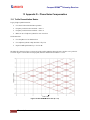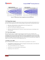
1
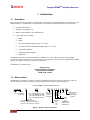
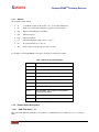
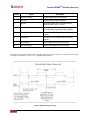
ISO 9001:2008 Certified Installation and Operation Manual Compact RDMSTM Telemetry Receiver Quasonix, Inc. 6025 Schumacher Park Dr. West Chester, OH 45069 06 November 2014 Revision 2.1.2 No part of the document may be circulated, quoted, or reproduced for distribution without prior written approval from Quasonix, Inc. Copyright Quasonix, Inc., All Rights Reserved. Compact RDMSTM Telemetry Receiver Table of Contents 1 Introduction ............................................................................................................................................ 1 1.1 Description................................................................................................................................... 1 1.2 Nomenclature .............................................................................................................................. 1 1.2.1 Options .................................................................................................................................... 2 1.2.2 Detailed Option Descriptions................................................................................................... 2 1.2.3 Band Configurations ................................................................................................................ 5 2 Specifications......................................................................................................................................... 2 3 Installation Instructions .......................................................................................................................... 4 3.1 Mechanical................................................................................................................................... 4 3.2 Thermal........................................................................................................................................ 1 3.3 Electrical ...................................................................................................................................... 1 4 Operating Instructions............................................................................................................................ 4 4.1 Power-on Operation..................................................................................................................... 4 4.2 Stored Parameters....................................................................................................................... 4 4.3 RDMS Serial Control Protocol ..................................................................................................... 5 4.3.1 5 Tier 0 (PCM/FM), Tier I (SOQPSK-TG), and Tier II (Multi-h CPM) Commands ..................... 7 Performance Specifications ................................................................................................................. 20 5.1 DC Input..................................................................................................................................... 20 5.2 RF Frequency Error ................................................................................................................... 20 5.3 Bit Error Rate ............................................................................................................................. 20 5.4 Synchronization ......................................................................................................................... 21 5.4.1 RF Input................................................................................................................................. 23 6 IF Module ............................................................................................................................................. 25 7 Maintenance Instructions..................................................................................................................... 30 8 Product Warranty ................................................................................................................................. 31 9 Technical Support and RMA Requests ............................................................................................... 32 10 Appendix A – Bit Error Rate Testing ................................................................................................ 33 11 Appendix B – Pinouts for Optional 37 Pin Connector ...................................................................... 37 12 Appendix C – Detailed Output Control (OC) Command Settings .................................................... 39 13 Appendix D – Phase Noise Compensation...................................................................................... 41 13.1 Trellis Demodulation Basics ...................................................................................................... 41 13.1.1 Trellis Demodulation Summary......................................................................................... 42 13.2 Phase Noise Impact................................................................................................................... 43 13.3 Clock Jitter Impact ..................................................................................................................... 43 13.4 When to Use PNC ..................................................................................................................... 43 i Quasonix, Inc. Compact RDMSTM Telemetry Receiver 13.5 Know Your Transmitter .............................................................................................................. 44 14 Appendix E – Factory Reset Values ................................................................................................ 45 15 Appendix F – Acronym List .............................................................................................................. 49 List of Figures Figure 1: Receiver Types and Options ......................................................................................................... 1 Figure 2: RDMS™ in 4.00” x 3.00” x 1.00” Compact Housing...................................................................... 5 Figure 3: MDM-15 Pin Numbers ................................................................................................................... 1 Figure 4: Baseband Signal Timing................................................................................................................ 2 Figure 5: RDMS™ Welcome Message ......................................................................................................... 6 Figure 6: BER Performance for Tier 0, I, and II .......................................................................................... 21 Figure 7: Synchronization Time at Various Signal-to-Noise Ratios ............................................................ 22 Figure 8: 70 MHz IF Module in 2” x 3” Chassis........................................................................................... 25 Figure 9: 70 MHz IF Module in 2” x 3” Chassis SAW Filter Responses, Narrow Group (10 MHz Span) ... 26 Figure 10: SAW Filter Responses, Wide Group (Plotted on 100 MHz Span)............................................. 27 Figure 11: Optional SAW Filter Responses for 70 kHz to 6 MHz ............................................................... 28 Figure 12: Optional SAW Filter Responses for 14 MHz and 28 MHz ......................................................... 29 Figure 13: Optional 37-Pin Numbers .......................................................................................................... 37 Figure 14: Ideal PCM/FM Phase Tree (h = 0.7).......................................................................................... 41 Figure 15: Phase Trajectory Never Forgets................................................................................................ 42 Figure 16: Trellis Detection Gain with Zero to Minimum Phase Noise ....................................................... 42 Figure 17: Trellis Detection Gain with Significant to Severe Phase Noise ................................................. 43 Figure 18: "Clean" Eye Pattern ................................................................................................................... 44 List of Tables Table 1: Model Configuration Example......................................................................................................... 2 Table 2: Band Configuration Codes.............................................................................................................. 5 Table 3: MDM-15 Pin Assignments .............................................................................................................. 1 Table 4: Default Modulation Start Up............................................................................................................ 4 Table 5: Stored Parameters .......................................................................................................................... 4 Table 6: Standard and Optional User Commands........................................................................................ 7 Table 7: RDMS BER Specifications............................................................................................................ 20 Table 8: Band Configuration Codes............................................................................................................ 23 Table 9: Bit Error Rate Serial Commands................................................................................................... 33 ii Quasonix, Inc. Compact RDMSTM Telemetry Receiver Table 10: Optional 37-Pin Assignments...................................................................................................... 37 Table 11: QPSK Factory Reset Values....................................................................................................... 45 Table 12: PCM/FM Factory Reset Values .................................................................................................. 46 Table 13: SOQPSK Factory Reset Values ................................................................................................. 47 Table 14: Multi-h CPM Factory Reset Values............................................................................................. 48 iii Quasonix, Inc. Compact RDMSTM Telemetry Receiver 1 Introduction 1.1 Description This document describes the installation and operation of the Quasonix Compact RDMS™ Telemetry Receiver. The RDMS™ (Receiver / DeModulator / bit Synchronizer) is designed to demodulate RF signals in several formats: PCM/FM (ARTM Tier 0) SOQPSK-TG (ARTM Tier I) Multi-h CPM (ARTM Tier II or ARTM CPM) Legacy (PSK) suite, including BPSK QPSK Asymmetric QPSK (AQPSK) Requires -37 option Asymmetric Unbalanced QPSK (AUQPSK) Requires -37 option Offset QPSK (OQPSK) Unbalanced QPSK (UQPSK) Digital PM The RDMS™ provides true trellis demodulation in ARTM Tier 0, Tier I, and Tier II modes, delivering BER performance within 0.2 dB of theory. It also provides a clock signal (two clock signals in the AQPSK and AUQPSK modes), obviating the need for any outboard bit synchronizer. The RDMS™ is manufactured by: Quasonix, Inc. 6025 Schumacher Park Drive West Chester, OH 45069 CAGE code: 3CJA9 1.2 Nomenclature The RDMS™ is available in a number of variations, depending on the options specified at the time of order. The features and modes installed in each unit are identified in the model number, as depicted in Figure 1. Compact RDMS™ Part Numbering Example QSX-RDMS - 1 - Quasonix, Inc. Legacy Extended Tuning: 1: Yes 0: No Figure 1: Receiver Types and Options 1 ARTM CPM Channels 1: 1 RF input, 1 baseband output 2: 2 RF I/Ps, 2 bbnd O/Ps (no combiner) 3: 2 RF I/Ps, 3 bbnd O/Ps (incl. combiner) Frequency Band Code (Refer to band table) 0 - 1 1 1 0 - 00 - EQ PCM/FM Chassis A15: 15-pin MDM Male TTL O/Ps A37: 37-pin MDM Male TTL O/Ps C15: 15-pin MDM Male 422 O/Ps C37: 37-pin MDM Male 422 O/Ps Q SOQPSK* Standard Receiver/ Prefix Demodulator/ Synchronizer A15 Pinout Options, separated by hyphens (example Adaptive Equalizer) Mode 1: Yes 0: No *SOQPSK-TG *SOQPSK-LDPC *SOQPSK-STC Compact RDMSTM Telemetry Receiver 1.2.1 Options The available options include: 14 14 SAW filter option (Adds 70 kHz, 1.4, 3, 6, 14, and 28 MHz filters) 8F Eight-way clock and data multiplexer (requires 37-pin connector) DR Double rate SOQPSK-TG (46 Mbps) EN Ethernet Payload EQ Adaptive Equalizer ET Extended temperature range (-40°C to +85°C) K7 K7 Viterbi Decoder (k=7, rate 1/2) WV Wide voltage operating range (15 VDC - 35 VDC) For example, a model QSX-RDMS-1-A15-Q0-1110-00-EQ is configured as follows: Table 1: Model Configuration Example Identifiers 1.2.2 Description QSX Quasonix product R Receiver / Demodulator / Bit Synchronizer DMS Demodulator / Bit Synchronizer 1 Channels A15 15-pin MDM Male TTL Outputs Q Frequency band code 0 No Extended Tuning 1110 Tier 0 present, Tier I present, Tier II present, Legacy (PSK) absent 00 Pinout EQ Adaptive Equalizer option Detailed Option Descriptions 1.2.2.1 SAW Filter Option – 14 This option adds additional SAW filters, for a total of 14. Additional filters are 70 kHz, and 1.4, 3, 6, 14, and 28 MHz. 2 Quasonix, Inc. Compact RDMSTM Telemetry Receiver 1.2.2.2 Eight-way Clock and Data Multiplexer – 8F Normally, the three clock and data streams available on the MDM-37 are Clock and Data A (the primary), Clock and Data B (the secondary for asynchronous PSK modulations), and Clock and Data C (what would normally be the primary for the combiner channel in a rack mount configuration). The 8F option allows the user to designate what information comes out on these pins by way of an eight-way multiplexer (MUX). (Though there are a total of four pairs of clock and data, there are only enough pins to allow access to three pairs in the compact configuration.) This makes it possible for the information from the primary Clock and Data to be copied to the secondary and tertiary set of outputs, giving the user three simultaneous copies of the information. The 8F option also requires the -37 option to be installed on the receiver. 1.2.2.3 Double Rate - DR The DR option provides double-speed SOQPSK-TG (46 Mbps). This option extends the standard upper bit rate limit from 23 Mbps to 46 Mbps 1.2.2.4 Ethernet Payload - EN When the EN option is enabled, all transmitted clock and data signals are serialized Ethernet packets. 1.2.2.5 Adaptive Equalizer - EQ The Adaptive Equalizer option in the Quasonix receiver improves reception in multipath channels by using digital signal processing to compensate for the signal distortion due to multipath. This option is compatible with standard telemetry applications and installations and it works with any brand of transmitter. Multipath fading can seriously degrade the quality of wireless telemetry data. Radio transmissions can reflect off of the airframe or other objects and arrive at the receiving antenna with different time delays, carrier phases, and relative strengths. The sum of these multiple transmission paths can produce serious distortion and signal fading resulting in poor data quality and long periods of data outage. Contrary to most situations, increasing the transmit power will not improve the link quality and may actually make the situation worse. Narrowing the beamwidth of the antenna may help eliminate some of the reflections and reduce the overall fading and distortion, but constraints on dish size and antenna tracking performance impose beamwidth limits. Another solution is to mitigate the effects of the multipath channel by applying a filtering operation at the receiver that effectively undoes the distortion caused by the channel, thereby 'equalizing' the received signal. Since the transmitter is typically moving relative to the receiver, the RF propagation environment dynamically changes over time requiring the equalizer to 'adapt' to continually combat the perceived channel distortion. The 'adaptive equalizer' automatically calculates and applies a compensating filter to the received signal that restores its ability to be recovered by a traditional telemetry detector. 1.2.2.6 Extended Temperature - ET The ET option specifies an extended operating temperature range (-40°C to +85°C). 1.2.2.7 Viterbi Decoder (for Legacy PSK Only) - K7 The K7 option (k=7, rate 1/2) enables Viterbi decoding of a convolutionally encoded data stream, which converts it back to the original (uncoded) source data stream. Convolutional encoding adds redundant information to the transmitted data stream to help detect and correct bit errors that may occur, particularly due to predominantly Gaussian noise. Use of convolutional encoding requires a matching Viterbi decoder in the receiver to extract the source data. The decoded data rate is half the encoded data rate. 3 Quasonix, Inc. Compact RDMSTM Telemetry Receiver The receiver has two independent decoders, one for in-phase (“I”) data and one for quadrature (“Q”) data. For BPSK, only a single decoder is used. Each decoder is compatible with the convolutional encoding described in the “Consultative Committee for Space Data Systems, Recommendation for Space Data System Standards, TM Synchronization and Channel Coding, CCSDS 131.0-B-1, Blue Book, September 2003, Section 3.” 1.2.2.8 Wide Voltage – WV This option specifies a wide voltage operating range (15 VDC - 35 VDC). 4 Quasonix, Inc. Compact RDMSTM Telemetry Receiver 1.2.3 Band Configurations Band configuration codes are listed in Error! Reference source not found.. Two additional band codes are described in section 1.2.3.1. Table 2: Band Configuration Codes 200.0 1415.0 Extended 400.0 Base P 1150.0 1435.5 Extended Base 1585.0 1534.5 Lower L Extended 1650.0 1750.0 Base Legend: Frequency Gap Standard (Base) Frequency Range Extended Frequency Range (available by selecting Extended Tuning = 1 in part number) Quasonix, Inc. 1850.0 Upper L Freq. Code A C E F G H L M P Q R S U W X Y Z 5 1855.0 2185.0 2200.0 Extended Base S Extended 2500.0 2394.5 4400.0 Base C 5250.0 5150.0 Compact RDMSTM Telemetry Receiver 1.2.3.1 Additional Band Codes Two additional band codes are available: Band Code 7: 70 MHz standard range, 0.5 MHz-20 MHz, 70 MHz extended range Band Code T: 2025.0 MHz to 2110.0 MHz standard range 1 Quasonix, Inc. Compact RDMSTM Telemetry Receiver 2 Specifications Characteristic Specification Receiver Section Type Dual-conversion superheterodyne Input RF Frequency Refer to Table 2 Tuning resolution Tunes in 62.5 kHz increments, to the 70 MHz IF output, after the 70 MHz IF output, receiver tunes in increments of less than 1 Hz Frequency stability 1 ppm over temperature 1 ppm per year aging Reference oscillator 20 MHz Noise figure 3.5 dB (typical), 5 dB (maximum) LO phase noise, measured at 70 MHz IF output -115 dBc/Hz @ 1 MHz offset Maximum RF input +20 dBm (+10 dBm for C-band) Available gain (to 70 MHz IF output) 114 dB Gain control 128 dB control range; User selectable: AGC or MGC (AGC freeze) AGC time constant Adjustable, 0.1 ms to 1000 ms First IF bandwidth 60 MHz (nominal) IF rejection > 90 dB Image rejection 70 dB RF input impedance 50 ohms Second IF Section IF frequency 70 MHz IF output level 0 dBm nominal (AGC mode) IF output impedance 50 ohms IF bandwidths 250 kHz, 500 kHz, 1 MHz, 2 MHz, 4.5 MHz, 10 MHz, 20 MHz, 40 MHz. Automatic selection based on data rate, with manual override Optional: 70 kHz, 1.4 MHz, 3 MHz, 6 MHz, 14 MHz, 28 MHz 2 Quasonix, Inc. Compact RDMSTM Telemetry Receiver Demodulator Section ARTM Tier 0 (PCM/FM), ARTM Tier I (SOQPSK-TG), ARTM Tier II (Multih CPM) Demodulator type Legacy suite: Analog FM, BPSK, QPSK, Offset QPSK (OQPSK), Asymmetric QPSK (AQPSK), Unbalanced QPSK (UQPSK), Asymmetric Unbalanced QPSK (AUQPSK), Digital PM Bit Rates Tier 0: 24 kbps to 23 Mbps in 1 bps steps Tier I: 100 kbps to 46 Mbps in 1 bps steps Tier II: 1 Mbps to 46 Mbps in 1 bps steps Legacy: 25 kbps to 20 Mbps in Analog FM, 50 kbps to 10 Mbps in BPSK, 50 kbps to 20 Mbps in QPSK in 1 bps steps Synchronization time(Average, at BER = 1e-5) Tier 0: 250 bits, Tier I: 385 bits, Tier II: 2,800 bits Tier 0: -8.0 dB Eb/N0; RF Input (dBm): -118.0 (1 Mbps), -108.0 (10 Mbps) Synchronization threshold Tier I: -6.0 dB Eb/N0; RF Input (dBm): -116.0 (1 Mbps), -106.0 (10 Mbps) Tier II: -7.0 dB Eb/N0; RF Input (dBm): -117.0 (1 Mbps), -107.0 (10 Mbps) Tier 0: 8.6 dB Eb/N0; RF Input (dBm): -101.4 (1 Mbps), -91.4 (10 Mbps) Sensitivity (BER = 1e-5) Tier I: 11.2 dB Eb/N0; RF Input (dBm): -98.8 (1 Mbps), -88.8 (10 Mbps) Tier II: 13.0 dB Eb/N0; RF Input (dBm): -97.0 (1 Mbps), -87.0 (10 Mbps) Bit Synchronizer Section Input codes NRZ-L/M/S, BIФ-L/M/S Output codes NRZ-L/M/S, BIФ-L/M/S Data and clock out TTL or RS-422 Lock detector out RSSI TTL Single 0 – 3.3 VDC, 2 MHz bandwidth (-37 option required) Video out Dual wideband outputs, DC to 35 MHz (-37 option required) Environmental Section Operating Temperature Non-operating Temperature Operating Humidity Vibration Acceleration Shock Altitude Physical Section Size / Weight Connectors Power 3 Quasonix, Inc. -20°C to +70°C -40°C to +85°C 0 to 95% (non-condensing) 20 G, 5 Hz to 2 kHz (all axes) 100 G (all axes) 100 G pk, half-sine, 5 ms (all axes) Up to 100,000 ft. 4.00” x 3.00” x 1.00” / 11 oz. RF input: SMA female IF output: SMA female Baseband: MDM-15 or MDM-37 (-37 option) 28 VDC ± 4 VDC, 750 mA typical Compact RDMSTM Telemetry Receiver 3 Installation Instructions 3.1 Mechanical The Compact RDMS™ is designed to be mounted by eight (8) 6-32 screws through the holes along the front and back edges, as depicted in Figure 2 on the following page. 4 Quasonix, Inc. Compact RDMSTM Telemetry Receiver Figure 2: RDMS™ in 4.00” x 3.00” x 1.00” Compact Housing 5 Quasonix, Inc. Compact RDMSTM Telemetry Receiver 3.2 Thermal It is important that the RDMS™ be kept within its specified operating range of -40°C to +70°C. At maximum bit rates, the unit dissipates approximately 20 watts. At normal ambient room temperatures, a small fan blowing across the top cover is adequate. Higher ambient temperatures will require more airflow and/or a finned heat sink on the cover. 3.3 Electrical The RDMS™ has three external connectors, an MDM-15 male for all baseband interfaces, a female SMA connector for the RF input, and a second female SMA connector for an IF output. Note that first generation hardware did not include the IF output. The pin numbering and wiring for the MDM-15 male connector is shown in Figure 3. Refer to Appendix B for optional 37 pin information. Figure 3: MDM-15 Pin Numbers Table 3: MDM-15 Pin Assignments Position Signal Description 1 +28 VDC Primary 28 VDC power to module 2 Ground Primary power return, 2 amps maximum; Internally tied to pins 3, 6, and 10 3 Ground Primary power return, 2 amps maximum; Internally tied to pins 2, 6, and 10 4 Clock Out Primary LVTTL clock output, Clock+ for RS 422 output 5 Data Out Primary LVTTL data output, Data+ for RS 422 output 6 232 Ground Ground return for RS-232 control lines; Internally tied to pins 2, 3, and 10 7 Demod Lock Out 3.3 volt TTL lock detector output for all modes 1 Quasonix, Inc. Compact RDMSTM Telemetry Receiver Position Signal Description 8 RS 232 Tx Output RS-232 responses to host controller 9 +28 VDC Primary 28 VDC power to module 10 Ground Secondary power return, 2 amps maximum; Internally tied to pins 2, 3, and 6 11 Power ON Power on reset pin; Temporarily grounding this pin is equivalent to power cycling the module 12 Clock Return Ground for LVTTL outputs, Clock- for RS 422 outputs 13 Data Return Ground for LVTTL outputs, Data- for RS 422 outputs 14 Ones Detect LVTTL signal use for sync time testing 15 RS 232 Rx Input RS-232 commands from host controller By default, the output data is valid on the falling edge of the clock, as shown in Figure 4. The polarity of the output clock may be inverted by use of the “CP 1” command described below. Figure 4: Baseband Signal Timing 2 Quasonix, Inc. Compact RDMSTM Telemetry Receiver The 70 MHz IF output on the second SMA connector, labeled “IF OUT”, is provided for troubleshooting purposes. The IF is resistively coupled from the input of the demodulator. Therefore, the signal level on the IF output should be within 2 dB of the demodulator’s input. The IF output must have a 50-ohm load at all times. Therefore, if it is not connected to external test equipment, then the 50-ohm terminator that comes installed on the port must remain attached. 3 Quasonix, Inc. Compact RDMSTM Telemetry Receiver 4 Operating Instructions 4.1 Power-on Operation When the receiver is powered up, the integral demodulator defaults to a particular modulation mode, which is based on the configuration of the unit. The modulation mode priority is outlined in Table 4. Table 4: Default Modulation Start Up Startup Order 4.2 Modulation 1 Legacy PSK 2 PCM/FM (Tier 0) 3 SOQPSK (Tier I) 4 Multi-h CPM (Tier II) Stored Parameters The following parameters are stored in the unit’s nonvolatile flash memory. The descriptions and default values are listed in Table 5. As with the Quasonix part number ordering method, parameters are typically stored in binary format. That is, “1” designates the feature is enabled, “0” designates the feature is disabled. Table 5: Stored Parameters Parameter Name Description Default Value Bit Rate 24 kbps - 40 Mbps depending on mode 1 Mbps Clock Polarity 1 or 0, denoting clock polarity inverted or not, respectively 0 (inversion OFF) Data Polarity 1 or 0, denoting data polarity inverted or not, respectively 0 (inversion OFF) De-Randomizer 1 or 0, denoting derandomizer ON or OFF, respectively 0 (de-randomizer OFF) Differential Decoding 1 or 0, depending on whether differential decoding is ON 1 (differential decoding ON) This is only meaningful for SOQPSK-TG modulation. Note: IRIG 106-04 stipulates the use of differential encoding, so operation without differential encoding is only possible with a demodulator operating in a “non-IRIG 106” mode. 4 Quasonix, Inc. Compact RDMSTM Telemetry Receiver Parameter Name Frequency Description This is the desired frequency of the receiver in MHz. Default Value 1450.5 MHz, 1800.5 MHz, or 2370.5 MHz for Lower-L band, Upper-L band, or S band, respectively 1450.5 MHz for tri band 4675.0 MHz for C band Modulation This is the modulation method used. Value of 0-10 QPSK, if it exists Options are: If not, then SOQPSK 0 - PCM/FM If not, then MHCPM If not, then PCM/FM 1- SOQPSK 2 - MHCPM 3 - BPSK 4 - QPSK 5 - AQPSK 6- AUQPSK 7 - OQPSK 8 - UQPSK 9 - DPM 10 - FM Modulation Index Tracking* In PCM/FM mode only A (Auto Tracking) Allows Trellis demodulator to automatically detect and adjust to Modulation Indices not at ideal 0.7 *Note: If the user cannot guarantee that the transmit source is a new generation, digitally synthesized transmitter, the receiver should be left in Tracking mode. Failure to do so will cause the receiver to fail to acquire improperly deviated signals altogether. All tracking loops are already optimized for fastest synchronization, and should not be adjusted in any way. If the user knows for sure that the transmit source is digitally synthesized, the tracking should be set to Off, for the minimum acquisition time. 4.3 RDMS Serial Control Protocol The Compact RDMS™ is controlled via a simple three-wire serial interface (transmit, receive, and ground). Configure your controller’s serial port to the following settings: Baud rate of 115,200 8 bits No parity 1 stop bit 5 Quasonix, Inc. Compact RDMSTM Telemetry Receiver For setup and configuration via a standard Windows-based PC, Quasonix recommends the application called Terminal, a flexible, full-featured control interface that is included in the RDMS Product CD. Otherwise, one can use HyperTerminal, included with the standard Windows installation (Start -> All Programs -> Accessories -> Communications -> HyperTerminal). When power is applied to the receiver, the welcome message, shown in Figure 5, displays. Initializing... downconverter init... Quasonix Demod/Receiver Interface IRIG-106 Release 07 6025 Schumacher Park Drive West Chester, Oh 45069 (513) 942-1287 www.Quasonix.com <http://www.Quasonix.com> CAGE CODE: 3CJA9 FPGA Revision: 0x3132 0x0000 PSK FW Revision: 2.0.043 7/29/2008 PSK> Figure 5: RDMS™ Welcome Message All commands are one or two alphabetic characters, followed by 0, 1, or 2 arguments. If the command is issued with arguments, there must be a space after the alphabetic characters. The commands are not case sensitive. All commands generate a response of one or more lines. The length of the response depends on the verbosity level (set by the VL command). The last response line is always the currently selected mode (PCM/FM, SOQPSK, CPM, or PSK), followed by the character “+” or “>”, depending on the version of the firmware. This prompt signifies that the RDMS is ready to accept new characters. 6 Quasonix, Inc. Compact RDMSTM Telemetry Receiver 4.3.1 Tier 0 (PCM/FM), Tier I (SOQPSK-TG), and Tier II (Multi-h CPM) Commands The following table describes all receiver user commands. Listed are the command code, name, description of the command, whether specific options must be ordered or the command is standard on all receivers, basic or advanced command, and whether the command is restricted to specific waveform modes. Note: If a user issues a command that does not apply to a given mode, an "Invalid Command" message is displayed. Any command that is valid in a mode but is disabled due to the option not being installed, returns an "Option Not Installed" message. Table 6: Standard and Optional User Commands Mnemonic Name Description Option (s) Required Basic or Advanced Command Mode Restriction ? Help Message Displays abbreviated list of available commands Standard Basic None AD Downconvert Antenna AD Report the downconvert antenna state **Standard Basic None Standard Basic None AD 0 Set downconvert antenna state to OFF (Disabled) AD 1 Set downconvert antenna state to ON (Enabled) **Downconverting antenna control only available when using a 5-band downconverter AND P and C bands are available on the unit. (applies to customers using downconverting antennas for C-band) AE AGC Enable Enable or Disable Automatic Gain Control (AGC) Examples: AE Report AGC state AE 0 Set AGC state to OFF (Disabled) AE 1 Set AGC state to ON (Enabled) 7 Quasonix, Inc. Compact RDMSTM Telemetry Receiver Mnemonic AV Name Manual Attenuator Control Description Report or set the value of the input attenuator Option (s) Required Basic or Advanced Command Mode Restriction Standard Basic None Valid range is 0 to 124 dB Examples: AV Report the input attenuator setting AV 0 Set input attenuator to 0 dB AV 124 Set input attenuator to 124 dB BE Bit Error Rate For Bit Error Rate commands and information, refer to Appendix A, Bit Error Rate Testing. Standard Advanced Command None BL Break Lock Breaks false locks Standard Basic PSK (legacy) No additional parameters BM Bit Rate Measurement Report bit rate measurement Standard Basic PSK (legacy) BR Bit Rate Report or set baseband bit rate Standard Basic For Asynch PSK (legacy) modes, BR A and BR B must be specified separately K7 Basic PSK (legacy) Examples: BR Report the bit rate setting BR 5 Mbps Set bit rate to 5 BR 0.6 Set bit rate to 600 Kbps CC Convolutional Decoder Enable Enables or disables the convolutional decoder Examples CC Report convolutional decoder state CC 0 Set the convolutional decoder to Disabled CC 1 Set the convolutional decoder to Enabled 8 Quasonix, Inc. Compact RDMSTM Telemetry Receiver Mnemonic CP Name Clock Polarity Description Report or set clock polarity inversion state Option (s) Required Basic or Advanced Command Standard Basic For Asynch PSK (legacy) modes, CP A and CP B must be specified separately Standard Basic SOQPSK Standard Basic For Asynch PSK (legacy) modes, DP A and DP B must be specified separately Standard Advanced Command None Examples: CP Report the clock source state DE Differential Decoder Enable CP 0 OFF Set clock inversion CP 1 ON Set clock inversion Report or set differential decoding Mode Restriction Examples: DE Report the differential decoding setting DE 0 Set differential decoding OFF DE 1 Set differential decoding ON DP Data Polarity Report or set data polarity inversion state Examples: DP Display the current data polarity DP 0 Set data polarity to NOT inverted (OFF) DP 1 Set data polarity to inverted (ON) FL Force Lock Indication Diagnostic tool to force the system to indicate locked or unlocked status; primarily used to verify wiring setup Examples: 9 Quasonix, Inc. FL state Show the force lock FL 1 Force lock to ON FL 0 Force lock to Normal FL -1 Force lock to OFF Compact RDMSTM Telemetry Receiver Mnemonic FR Name Frequency Description Option (s) Required Basic or Advanced Command Mode Restriction Standard Basic None Report or set the current IF filter in the receiver Standard Basic None FS Display the current IF filter -14 option permits 7 additional filters Standard Basic None Standard Basic None Report or set receiver center frequency Examples: FR Report the frequency setting FR 2200.5 Set modulation to 2200.5 MHz FS IF Filter Select FS A to automatic Set IF filter FS (0-7) Manually set IF filter (not recommended) GO Start/Restart Apply changes then reset demodulator. Initiate demodulation with current parameters. This command is required when setting both the modulation and the bit rate. GO command is issued any time the bit rate is changed. This forces the demodulator to rescale all of its loop parameters and digital filtering so they are set properly for the bit rate. HX eXtended Help 10 Quasonix, Inc. Displays a full list of available commands Compact RDMSTM Telemetry Receiver Mnemonic LD Name Description LDPC Decode Enable Enable, disable, or show the current state of the Forward Error Correction (FEC) / Low Density Parity Check (LDPC) decoder Option (s) Required LD Basic or Advanced Command Advanced Command Mode Restriction PSK (legacy) Select mode 7 (OQPSK) Examples: LD Show the current decoder state LD 1 Enable the LDPC decoder LD 0 Disable the LDPC decoder LP Lock Output Polarity Report or set the active level of the lock indication to active high or active low Standard Advanced Command None Standard Basic None Examples: LP Show the current lock output polarity LP 1 Set the active level to high LP 0 Set the active level to low MA Modulations Allowed 11 Quasonix, Inc. Report the available waveform modes (modulations) available for this unit Compact RDMSTM Telemetry Receiver Mnemonic MI Name Modulation Index Description Report or Set Modulation Index Tracking or Acquire Examples MI Report Mod Index Track Status MI O Disable Mod Index Tracking (Set to h=0.7) MI A Acquire mode enable MI A D Sets the maximum delta h (indicates a change in h defaults to 0.005) MI A S Sets the delta h settling time defaults to 500 ms MI H Hold Mod Index Tracking at current position MI I Sets Trellis Index MI T Tracking mode enable MI T H x Sets the Tracking Hold threshold 12 Quasonix, Inc. Option (s) Required Standard Basic or Advanced Command Basic Mode Restriction PCM/FM Compact RDMSTM Telemetry Receiver Mnemonic MO Name Modulation Description Report or set modulation setting Option (s) Required Basic or Advanced Command Mode Restriction Standard Basic Limited to modes installed Standard Advanced Command PCM/FM and PSK (legacy) Examples: MO Report the modulation setting MO 0 Set modulation to PCM/FM MO 1 Set modulation to SOQPSK-TG MO 2 Set modulation to Multi-h CPM MO 3 Set modulation to BPSK MO 4 Set modulation to QPSK MO 5 Set modulation to AQPSK MO 6 Set modulation to AUQPSK MO 7 Set modulation to OQPSK MO 8 Set modulation to UQPSK MO 9 Set modulation to Digital PM (DPM) NZ NRZ Encoding Report or set the non-return to zero (NRZ) value used by the receiver Examples: NZ Show the current NRZ value NZ L Set the NRZ to Level NZ M (1) Set the NRZ to Mark NZ S Set the NRZ to Space 13 Quasonix, Inc. Compact RDMSTM Telemetry Receiver Mnemonic OC Name Output Control Description Report or set the channel source values Option (s) Required Basic or Advanced Command Mode Restriction 8F and -37 Basic None Standard Advanced Command None Standard Basic None Examples: OC Show current OC settings OC D Set the default outputs OC c s Set the channel and clock source For detailed syntax information, refer to Appendix C OM Output Muting Report or set the operation of clock and data output muting; clock and data outputs can be disabled after some period of time without lock Examples: OM Show the output muting state OM 0 Disables output muting OM 1 Enables output muting OM T x Sets the delay between loss of lock and muted outputs in milliseconds from 0 to 46016 PA Reset Stored Configuration Resets ALL parameters in ALL waveform modes to the factory default state and sets the receiver to the lowest default mode and lowest bit rate Refer to Appendix E for a list of factory default values by mode 14 Quasonix, Inc. Compact RDMSTM Telemetry Receiver Mnemonic PL Name Input Power Level Description Reports or sets the current input power level setting Option (s) Required Basic or Advanced Command Mode Restriction Standard Advanced Command None Standard Basic PCM/FM Standard Advanced Command None Standard Basic None Examples: PL Report the current input power level information tracking state PL 0 Set the current power level information tracking display to OFF PL 1 Set the current power level information tracking display to ON PL reports the Input signal level of the receiver, the signal level into the demod, the digitally scaled signal level, the SNR, and eb/N0 PN Phase Noise Compensation Report or set phase noise compensation state Examples: PN Report the phase noise compensation state PN 0 Set phase noise compensation to OFF PN 1 Set phase noise compensation to ON PR QT 15 Reset Defaults for Currently Selected Mode Restores factory default parameters for the currently selected mode on the unit Query Temperature Report the temperature in degrees Celsius Quasonix, Inc. Refer to Appendix E for a list of factory default values by mode Compact RDMSTM Telemetry Receiver Mnemonic RN Name Derandomizer State Description Report or set the derandomizer state Option (s) Required Basic or Advanced Command Mode Restriction Standard Basic None Examples: RN Report the derandomizer state RN 0 Set the derandomizer OFF RN 1 Set the derandomizer ON SN Show Serial Number Report the serial number for the unit Standard Basic None SV Save Parameters Saves the current parameters in non-volatile memory, including frequency, modulation, bit rate, data polarity, clock polarity, AGC state, verbosity level, etc. Standard Basic None 16 Quasonix, Inc. Compact RDMSTM Telemetry Receiver Mnemonic SY Name System Status Tracking Description Displays the system status of the receiver Option (s) Required Basic or Advanced Command Mode Restriction Standard Advanced Command Available for all EXCEPT PSK (legacy) 37 Advanced Command PCM/FM The first argument specifies the period, in milliseconds, between status updates. Zero (0) disables continuous monitoring. The second argument specifies the number of status lines between header output. Examples: SY Displays current status report settings SY 5 Sets status output period to 5 milliseconds SY 5 100 Sets status header output once every 100 status updates The SY command reports system status information about the timing and frequency tracking loops, as well as mod scaling, lock indication and eb/n0 data. This command is very effective for troubleshooting link issues. TO Tape Output Displays the status of the Tape Output option Example: TO Displays current tape output status settings (enabled/disabled and output frequency) 17 Quasonix, Inc. Compact RDMSTM Telemetry Receiver Mnemonic TO F Name Tape Output Frequency Description Sets the carrier frequency of the pre-detection complex Tape Output Option (s) Required Basic or Advanced Command Mode Restriction 37 Advanced Command PCM/FM 37 Advanced Command PCM/FM Standard Basic None Examples: TO F 0 Sets the Tape Output Frequency to Off (carrier frequency = 0 MHz) TO F 1 Sets the Tape Output Frequency to a specific frequency number Value range is 0.000 to 20.000 MHz TO T Tape Output Source Sets the test output to a Tape source; Enables or Disables the predetection complex baseband as the tape output source When enabled (T=1), predetection complex baseband is selected as the source of data to send on I and Q analog outputs When disabled (T=0), the I and Q analog outputs (frequency/phase information) are restored to their normal defaults which vary by mode Examples: TO T 0 Sets the Tape Output Source to disabled TO T 1 Sets the Tape Output Source to enabled VE Version 18 Quasonix, Inc. Report the current Firmware (software) version information for the receiver Compact RDMSTM Telemetry Receiver Mnemonic *VF Name Description Viterbi Forget Factor Report or set the Viterbi forget factor, on a scale from 0.01 – 0.99 Option (s) Required Basic or Advanced Command Mode Restriction Standard Advanced Command PCM/FM Standard Advanced Command None Standard Advanced Command None Examples: VF Report the Viterbi forget factor VF 0.04 Set the Viterbi forget factor to 0.04 VF 0.62 Set the Viterbi forget factor to 0.62 VL Verbosity Level Report or set verbosity level, on a scale of 0 – 9 Examples: VL Report the verbosity level VL 0 Set the verbosity level to 0 VL 5 Set the verbosity level to 5 ZZ Show Options Displays the current hardware configuration and options on the receiver *Note regarding VF command: The VF command sets the observation window for the Viterbi decoder in the trellis demod. The longer the window, the more coding gain. The smaller the window, the more resistant to phase noise. Quasonix recommends NOT manually changing this value. The Phase Noise Compensation mode automatically adjusts this as needed. 19 Quasonix, Inc. Compact RDMSTM Telemetry Receiver 5 Performance Specifications 5.1 DC Input The Compact RDMS™ operates from a nominal 28 VDC, +/- 4 VDC with a current consumption of no more than 25 Watts. 5.2 RF Frequency Error By default, the Compact RDMS™ is capable of acquiring a signal with a frequency error of up to ±100 kHz. 5.3 Bit Error Rate The RDMS™ meets the following BER limits, when tested with a signal source, which complies with IRIG 106-05. Table 7: RDMS BER Specifications BER Maximum Eb/N0 (dB) PCM/FM, Tier 0 SOQPSK-TG, Tier I Multi-h CPM, Tier II 10-3 7.5 9.5 11.0 10-4 9.0 11.5 12.5 10-5 10.0 13.0 13.5 10-6 11.0 14.5 14.5 Typical BER performance, plotted in Figure 6, is significantly superior to that tabulated above. 20 Quasonix, Inc. Compact RDMSTM Telemetry Receiver 1.E+00 1.E-01 1.E-02 1.E-03 1.E-04 1.E-05 Tier 0, QSX-DMS-111 1.E-06 Tier I, QSX-DMS-111 1.E-07 Tier II, QSX-DMS-111 1.E-08 2 3 4 5 6 7 8 9 Eb/N0 (dB) 10 11 12 13 14 Figure 6: BER Performance for Tier 0, I, and II 5.4 Synchronization The Compact RDMS™ offers very fast, reliable acquisition, even at very low signal to noise ratio. Synchronization time is a function of modulation type and IF frequency error. Typical SOQPSK results (from 10,000 synchronization trials) are shown in Figure 7. 21 Quasonix, Inc. Compact RDMSTM Telemetry Receiver Figure 7: Synchronization Time at Various Signal-to-Noise Ratios 22 Quasonix, Inc. Compact RDMSTM Telemetry Receiver 5.4.1 RF Input The Compact RDMS™ is available in frequency bands shown in Table 8. Two additional band codes are described in section 5.4.1.1. The input impedance is 50 ohms. Table 8: Band Configuration Codes 200.0 1415.0 Extended 400.0 Base P 1150.0 1435.5 Extended Base 1585.0 1534.5 Lower L Extended 1650.0 1750.0 Base Legend: Frequency Gap Standard (Base) Frequency Range Extended Frequency Range (available by selecting Extended Tuning = 1 in part number) Quasonix, Inc. 1850.0 Upper L Freq. Code A C E F G H L M P Q R S U W X Y Z 23 1855.0 2185.0 2200.0 Extended Base S Extended 2500.0 2394.5 4400.0 Base C 5250.0 5150.0 Compact RDMSTM Telemetry Receiver 5.4.1.1 Additional Band Codes Two additional band codes are available: Band Code 7: 70 MHz standard range, 0.5 MHz-20 MHz, 70 MHz extended range Band Code T: 2025.0 MHz to 2110.0 MHz standard range 24 Quasonix, Inc. Compact RDMSTM Telemetry Receiver 6 IF Module The receiver’s integrated IF filter module, shown in Figure 8, includes eight (8) SAW filters, ranging in bandwidth from 250 kHz to 40 MHz in approximately one octave steps. The standard eight filters are 250 kHz, 500 kHz, 1 MHz, 2 MHz, 4.5 MHz, 10 MHz, 20 MHz, and 40 MHz. These filters serve as anti-aliasing filters ahead of the A/D converter in the demodulator itself. In addition, they can provide an added measure of adjacent channel interference rejection. The measured responses of the eight filters are shown in Figure 9 and Figure 10 (note the change of horizontal scale between the two figures). Six additional filters are available allowing for a total of 14. The optional filters are 70 kHz, 1.4 MHz, 3 MHz, 6 MHz, 14 MHz, and 28 MHz. The measured responses of the optional filters are shown in Figure 11 and Figure 12. Contact Quasonix for information about the optional filters. Based on the receiver’s high level of integration, the proper IF filter is automatically selected based on the current mode and bit rate settings of the demodulator. Although manual filter selection is available, it is not recommended. Figure 8: 70 MHz IF Module in 2” x 3” Chassis The IF module attaches directly to the demod modules. 25 Quasonix, Inc. Compact RDMSTM Telemetry Receiver Figure 9: 70 MHz IF Module in 2” x 3” Chassis SAW Filter Responses, Narrow Group (10 MHz Span) 26 Quasonix, Inc. Compact RDMSTM Telemetry Receiver Figure 10: SAW Filter Responses, Wide Group (Plotted on 100 MHz Span) 27 Quasonix, Inc. Compact RDMSTM Telemetry Receiver Figure 11: Optional SAW Filter Responses for 70 kHz to 6 MHz 28 Quasonix, Inc. Compact RDMSTM Telemetry Receiver Figure 12: Optional SAW Filter Responses for 14 MHz and 28 MHz 29 Quasonix, Inc. Compact RDMSTM Telemetry Receiver 7 Maintenance Instructions The Compact RDMS™ requires no regular maintenance, and there are no user-serviceable parts inside. Please consult the factory for any maintenance, upgrade, or repair requirements. 30 Quasonix, Inc. Compact RDMSTM Telemetry Receiver 8 Product Warranty The Compact RDMS™ carries a standard parts and labor warranty of one (1) year from the date of delivery. 31 Quasonix, Inc. Compact RDMSTM Telemetry Receiver 9 Technical Support and RMA Requests In the event of a product issue, customers should contact Quasonix via phone (1-513-942-1287) or e-mail ([email protected]) to seek technical support. If Quasonix determines that the product issue must be addressed at the factory, a returned materials authorization (RMA) number will be provided for return shipment. Authorized return shipments must be addressed in the following manner: Quasonix, Inc. ATTN: Repair, RMA # 6025 Schumacher Park Drive West Chester, OH 45069 To ensure that your shipment is processed most efficiently, please include the following information with your product return: Ship To – Company name, address, zip code, and internal mail-drop, if applicable Attention/Contact person – Name, Title, Department, Phone number, email address Purchase Order Number – If applicable RMA Number – provided by the Quasonix representative Please note that Quasonix reserves the right to refuse shipments that arrive without RMA numbers. 32 Quasonix, Inc. Compact RDMSTM Telemetry Receiver 10 Appendix A – Bit Error Rate Testing There is a separate BERT for each data path in the receiver (0 main channel, 1 combiner channel). By default all commands are targeted to the current “tracking channel” (TC command), 0 or 1. If the tracking channel is set to 2 (tracking both channels), then the channel must be explicitly specified. The results of the test can be displayed using the BE command with no parameters or a continuous display can be produced using BE D 1. BE D 0 turns off the continuous display. Table 9: Bit Error Rate Serial Commands Mnemonic Name BE ? Bit Error Rate Help BE [c] Bit Error Rate Status Description Provides help for using the bit error rate commands Report bit error rate status [c] is optional and indicates channel 0 or 1 If channel is omitted, the current tracking channel (TC) is used If TC is 2, a channel number is required Examples: BE D Bit Error Rate Status Continuous BE Show the bit error rate status BE 1 Show the status of channel 1 Report a continuous display of bit error rate status Examples: BE D 0 Show continuous bit error rate status is OFF BE D 1 Show continuous bit error rate status is ON BE [c] P n Set Bit Error Test Pattern Sets bit error test pattern [c] is optional and indicates channel 0 or 1 If channel is omitted, the current tracking channel (TC) is used If TC is 2, a channel number is required P indicates a preset or fixed pattern length where 'n' is one of: PN6, PN9, PN11, PN15, PN17, PN20, PN23, PN31 or, for a fixed pattern length of 2 to 32 (fixed patterns are automatically determined) 33 Quasonix, Inc. Compact RDMSTM Telemetry Receiver Mnemonic BE [c] T n Name Set Bit Error Measurement Type Description Sets bit error measurement type The test type can be configured to run continuously or stop when either a time limit, bit count, or error count has been reached. The error count limit guarantees a minimum number of errors. [c] is optional and indicates channel 0 or 1 If channel is omitted, the current tracking channel (TC) is used If TC is 2, a channel number is required T indicates type where 'n' is one of the following: C = continuous (clears limits) T x = time limit where 'x' is between 0 and 4.29497E+06 seconds B x = bit limit where 'x' is between 0 and 9.3825E+13 E x = error limit where 'x' is between 0 and 3.1275E+13 BE G n Set Bit Error Measurement Gating Sets bit error measurement gating The test can be configured to make a single measurement or, when a time limit, bit count, or error count is set, automatically repeat the test. Examples: 34 Quasonix, Inc. BE G S S indicates Single BE G R R indicates Repeat Compact RDMSTM Telemetry Receiver Mnemonic BE [c] M Name Measurement Enable Description Starts or stops bit error measurement (toggle command) If a time limit, bit count, or error count limit is set and the limit has been reached (enabled but not running) the BERT is restarted. [c] is optional and indicates channel 0 or 1 If channel is omitted, the current tracking channel (TC) is used If TC is 2, a channel number is required Examples: BE M Enter command once to Start bit error measurement, current tracking channel BE M Enter command again to Stop bit error measurement current tracking channel BE 1 M Enter command once to Start bit error measurement, for channel 1 BE [c] R Hardware Bit Error Register Display Reports the bit error register status [c] is optional and indicates channel 0 or 1 If channel is omitted, the current tracking channel (TC) is used If TC is 2, a channel number is required Example: BE 1 R BE [c] W reg value Set Hardware Bit Error Register Report bit register state for channel 1 Sets hardware bit error register 'reg' to 'value' [c] is optional and indicates channel 0 or 1 If channel is omitted, the current tracking channel (TC) is used If TC is 2, a channel number is required ‘reg’ is hex register index 00 to 0a ‘value’ is 32 bit hex value to write to register The Hardware Bit Error Register Display reports the current status of the bit error rate test (BERT). A column header is displayed every ten rows. The 'E' column indicates the BERT is enabled by displaying a pound sign '#'. If the BERT is not enabled, this column is blank. The 'R' column indicates the BERT is actually running and making a measurement by displaying a '!'. If the BERT is not running, this column is blank. 35 Quasonix, Inc. Compact RDMSTM Telemetry Receiver The BERT can be enabled, but not running, in the case of a time, bit, or error count limit. An asterisk '*' after the error rate column indicates that the data is inverted. If the display is continuous and a time, bit, or error limit is set with repeating gating, the display shows the end of the test by displaying '>>>' in the first three columns. The following shows an example display with a five (5) second repeating test. E R # ! # ! # ! # ! # ! >>> # ! # ! # ! # ! # ! 36 Time 0:00:00:03.772 0:00:00:04.023 0:00:00:04.276 0:00:00:04.527 0:00:00:04.779 0:00:00:05.000 0:00:00:00.251 0:00:00:00.503 0:00:00:00.757 0:00:00:01.011 0:00:00:01.263 Quasonix, Inc. Bit Count 3.773e+07 4.023e+07 4.276e+07 4.528e+07 4.780e+07 5.000e+07 2.512e+06 5.032e+06 7.574e+06 1.011e+07 1.264e+07 Error Count 2 2 2 2 2 2 0 0 2 2 2 Error Rate 5.301e-08* 4.971e-08* 4.677e-08* 4.417e-08* 4.184e-08* 4.000e-08* 0.000e+00* 0.000e+00* 2.641e-07* 1.978e-07* 1.582e-07* Compact RDMSTM Telemetry Receiver 11 Appendix B – Pinouts for Optional 37 Pin Connector The optional 37-pin connector provides three sets of clock and data, two high-speed analog outputs, and one lowspeed analog output. Pin numbering for the optional connector is shown in Figure 13. Pin assignments are listed in Table 10. Figure 13: Optional 37-Pin Numbers Table 10: Optional 37-Pin Assignments Position Signal Description 1 DAC A Analog output (+/- 5VDC) 2 DAC B Analog output (+/- 5VDC) 3 RSSI Received Signal Strength Indication (0-3.3VDC) 4 Data C + Clock and Data pairs 5 DNC Factory use only – Do Not Connect 6 DNC Factory use only – Do Not Connect 7 +28 VDC In System power 8 Ground System power 9 Ground System power 10 Clock A + Clock and Data pairs 11 Data A + Clock and Data pairs 12 Serial Ground RS232 Serial Connection - Ground 13 Lock Detect LVTTL Indicator Line 14 Serial TXD RS232 Serial Connection - Transmit 15 Clock C + Clock and Data pairs 16 Clock B + Clock and Data pairs 17 Data B + Clock and Data pairs 18 DNC Factory use only – Do Not Connect 19 DNC Factory use only – Do Not Connect 37 Quasonix, Inc. Compact RDMSTM Telemetry Receiver Position Signal Description 20 DAC Ground Analog output (GND) 21 DNC Factory use only – Do Not Connect 22 Data C - Clock and Data pairs 23 DNC Factory use only – Do Not Connect 24 DNC Factory use only – Do Not Connect 25 SDI Signal Degradation Indication (RF Networks 2241) 26 +28 VDC In System power 27 Ground System power 28 Power on Reset 29 Clock A - Clock and Data pairs 30 Data A - Clock and Data pairs 31 Ones Detect LVTTL Indicator Line 32 Serial RXD RS232 Serial Connection - Received 33 Clock C - Clock and Data pairs 34 Clock B - Clock and Data pairs 35 Data B - Clock and Data pairs 36 DNC Factory use only – Do Not Connect 37 DNC Factory use only – Do Not Connect 38 Quasonix, Inc. Compact RDMSTM Telemetry Receiver 12 Appendix C – Detailed Output Control (OC) Command Settings The Output Control command, as described in Table 6, is used to report or set the channel source values. Note: The state settings use the alpha O, not a number zero (0). Mnemonic Name Description OC ? Help Message Displays abbreviated list of available commands OC Current Settings (This is an example - current settings will vary.) O_0 = CLK_I0 O_1 = DATA_I0 O_2 = CLK_Q0 O_3 = DATA_Q0 O_4 = CLK_I1 O_5 = DATA_I1 O_6 = CLK_Q1 O_7 = DATA_Q1 OC D Set Default Outputs O_0 = CLK_I0 O_1 = DATA_I0 O_2 = CLK_Q0 O_3 = DATA_Q0 O_4 = CLK_I1 O_5 = DATA_I1 O_6 = CLK_Q1 O_7 = DATA_Q1 39 Quasonix, Inc. Compact RDMSTM Telemetry Receiver Mnemonic OC c s Name Set Channel and Source Description where c is channel: O_0, O_1, O_2, O_3, O_4, O_5, O_6, O_7 where s is source: CLK_I0, DATA_I0, CLK_Q0, DATA_Q0, CLK_I1, DATA_I1, CLK_Q1, DATA_Q1, CLK_T, DATA_T, OFF When the outputs return the value above, this says the outputs are routed to the default settings. If anything is changes, an asterisk (*) appears before the changed parameter. For example, changing the secondary Clock and Data to match the primary commands are: OC O_2 CLK_I0 OC O_3 DATA_I0 When the changes are made, the list displays as follows: OC O_0 = CLK_I0 O_1 = DATA_I0 *O_2 = CLK_I0 *O_3 = DATA_I0 O_4 = CLK_I1 O_5 = DATA_I1 O_6 = CLK_Q1 O_7 = DATA_Q1 Now the user has the clock and data I0 (the letter I and the number 0), on both the primary (A channel) and secondary (B channel) outputs. These settings can be saved with the SV command, but are only saved per mode. If the user changes modes (using the MO command), they must repeat the settings for the other mode. 40 Quasonix, Inc. Compact RDMSTM Telemetry Receiver 13 Appendix D – Phase Noise Compensation 13.1 Trellis Demodulation Basics Legacy Single-Symbol Detection: Uses basic Limiter-Discriminator operation Frequency in this bit above nominal → data = 1 Frequency in this bit below nominal → data = 0 Makes no use of adjacent symbols for error correction Trellis Detection: Uses the phase tree for data detection Uses adjacent symbols to help decide on “iffy” bits Improves BER performance by 3.5 to 5.0 dB The Phase Tree shown in Figure 14, shows all of the possible paths the phase trajectory can take over a period of seven bits. Figure 15 shows the two unique paths, based on whether the second bit is a 1 or 0. Figure 14: Ideal PCM/FM Phase Tree (h = 0.7) 41 Quasonix, Inc. Compact RDMSTM Telemetry Receiver Figure 15: Phase Trajectory Never Forgets 13.1.1 Trellis Demodulation Summary The basic premise of trellis demodulation is that the signal from the transmitter follows a known path through the phase tree. When the demodulator knows this, it can use a sequence of several symbols to help make better decisions about each individual bit. This process improves BER performance by about 3.5 to 5 dB over conventional FM detection. However, this assumes that the transmitter is really following the "known" and "correct" phase tree, and this assumption is NOT always true. High phase noise can reduce the trellis detection gain because phase noise corrupts the tree. The following figures illustrate the differences in trellis detection gain depending on the amount of phase noise introduced. Figure 16: Trellis Detection Gain with Zero to Minimum Phase Noise 42 Quasonix, Inc. Compact RDMSTM Telemetry Receiver Figure 17: Trellis Detection Gain with Significant to Severe Phase Noise 13.2 Phase Noise Impact Trellis demodulation is based on the assumption that the signal is following a predictable path through the trellis. If this is not true (due to high phase noise), then a trellis demodulator cannot provide the expected performance gain. Many legacy analog transmitters (a simple modulated VCO) have high phase noise. Vibration often further increases phase noise. Phase noise is generally more damaging at low bit rates. Phase Noise Compensation (PNC) gives back some of the trellis detection gain, by shortening the trellis observation span. 13.3 Clock Jitter Impact Many older PCM encoders are susceptible to large inaccuracies in clock rate or have clock stability issues, especially under harsh vibration conditions. While the RDMS is capable of tracking static clock rate errors as large as 1000 ppM, excessive jitter causes the integrated bit sync to lose lock. Enabling the PNC mode opens the tracking loop bandwidth to accommodate for these issues. This increase in bandwidth does have a tradeoff. A wider tracking range allows the RDMS to deal with the additional jitter, but it may also increase synchronization times slightly, and slightly increase the minimum SNR at which the RDMS declares lock. 13.4 When to Use PNC There is no bullet-proof test for whether PNC is needed, but there are good indicators. Turn on PNC if: The demodulator is struggling to lock, even with good Signal to Noise Ratio (SNR). ("Good" SNR means the Quality bar is above one-quarter height.) The eye pattern NEVER looks “clean,” as in Figure 18 Symptoms get worse when the transmitter is under vibration Symptoms get worse at low bit rates 43 Quasonix, Inc. Compact RDMSTM Telemetry Receiver Figure 18: "Clean" Eye Pattern 13.5 Know Your Transmitter If you know the brand and type of transmitter, these tips can help determine when to use PNC. If your transmitter was manufactured by these companies, PNC should be OFF: Quasonix – guaranteed Nova Engineering – highly likely L3 – probably, but digital transmitters only If the transmitter was manufactured by the companies below, PNC should be ON: Microwave Innovations Emhiser Southern California Microwave L3 (analog transmitters) 44 Quasonix, Inc. Compact RDMSTM Telemetry Receiver 14 Appendix E – Factory Reset Values When a reset command is activated, the frequency defaults to the lowest valid frequency for the lowest authorized band on the unit. The reset priority is: 1. QPSK 2. PCM/FM 3. SOQPSK 4. Multi-h CPM Reset values for each mode are listed in the following tables. Table 11: QPSK Factory Reset Values Parameter Bit Rate Modulation Scaling 1 N/A Clock Polarity Normal Data Polarity Normal Derandomizer Disabled Differential Decoder N/A IF Filter Auto Downconvert Antenna Disabled AGC Enabled Convolutional Decoder Disabled Lock Output Polarity 45 Reset State Active High NRZ Encoding NRZ-L Output Control Default Output Muting Disabled Phase Noise Compensation Disabled Tape Output Disabled Quasonix, Inc. Compact RDMSTM Telemetry Receiver Table 12: PCM/FM Factory Reset Values Parameter Bit Rate 1 Modulation Scaling Tracking Clock Polarity Normal Data Polarity Normal Derandomizer Disabled Differential Decoder N/A IF Filter Auto Downconvert Antenna Disabled AGC Enabled Convolutional Decoder Disabled Lock Output Polarity 46 Reset State Active High NRZ Encoding NRZ-L Output Control Default Output Muting Disabled Phase Noise Compensation Disabled Tape Output Disabled Quasonix, Inc. Compact RDMSTM Telemetry Receiver Table 13: SOQPSK Factory Reset Values Parameter Bit Rate Modulation Scaling 1 N/A Clock Polarity Normal Data Polarity Normal Derandomizer Disabled Differential Decoder Enabled IF Filter Auto Downconvert Antenna Disabled AGC Enabled Convolutional Decoder Lock Output Polarity 47 Reset State N/A Active High NRZ Encoding N/A Output Control Default Output Muting Disabled Phase Noise Compensation Disabled Tape Output Disabled Quasonix, Inc. Compact RDMSTM Telemetry Receiver Table 14: Multi-h CPM Factory Reset Values Parameter Bit Rate Modulation Scaling 1 N/A Clock Polarity Normal Data Polarity Normal Derandomizer Disabled Differential Decoder N/A IF Filter Auto Downconvert Antenna Disabled AGC Enabled Convolutional Decoder Lock Output Polarity 48 Reset State N/A Active High NRZ Encoding N/A Output Control Default Output Muting Disabled Phase Noise Compensation Disabled Tape Output Disabled Quasonix, Inc. Compact RDMSTM Telemetry Receiver 15 Appendix F – Acronym List Acronym 49 Description AGC Automatic Gain Control AM Amplitude Modulation AQPSK Variant of Quadrature Phase Shift Keying ARTM Advanced Range Telemetry AUQPSK Variant of Quadrature Phase Shift Keying BER Bit Error Rate BNC Bayonet Neill-Concelman Connector (RF Connector) BPSK Binary Phase Shift Keying CD Compact Disk CPM Continuous Phase Modulation DB-9 D-subminiature 9 pin Serial Connector DC Diversity Combiner DHCP Dynamic Host Configuration Protocol DPM Digital Phase Modulation FPGA Field Programmable Gate Array IF Intermediate Frequency IP Internet Protocol kbps Kilobits per second KHz Kilohertz LCD Liquid Crystal Display Mbps Megabits per second MCX Snap on subminiature connector MHCPM multi-h Continuous Phase Modulation MHz Megahertz N (connector type) Threaded RF connector OQPSK Offset Quadrature Phase Shift Keying PCMFM Pulse Code Modulation/Frequency Modulation PM Phase Modulation Quasonix, Inc. Compact RDMSTM Telemetry Receiver Acronym 50 Description PSK Phase Shift Keying QPSK Offset Quadrature Phase Shift Keying RDMS Receiver DeModulator Synchronizer RF Radio Frequency RJ-45 Ethernet Connection Jack RM Rack Mount RRC Remote RDMS Client RS-232 Recommended Standard 232 (Serial Communications) SAW Surface Acoustic Wave SDI System Degradation Indication SOQPSK Shaped Offset Quadrature Phase Shift Keying SOQPSK-TG Shaped Offset Quadrature Phase Shift Keying –Telemetry Group TRL Tracking Loop TTL Transistor Transistor Logic UDP User Datagram Protocol UQPSK Unbalanced Quadrature Phase Shift Keying USB Universal Serial Bus VAC Voltage Alternating Current VDC Voltage, Direct Current WAN Wide Area Network Quasonix, Inc.