1
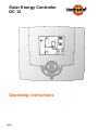
Solar Energy Controller
DC 12
Operating instructions
A0805
Contents
Warning
The controller is an electrically operateddevice. Improper installation or attempted repair can cause a life-threatening
electric shock hazard. Installation and
commissioning must be performed only
by adequately qualified specialist personnel.
There are no user serviceable parts inside. Do not open the controller except to
mount it and fit sensors and then only do
so when it is disconnected and in accordance with these instructions.
When the controller is open, the printed
circuit must be handled with utmost care.
Mechanical damage and any magnetic
or static charge from tools must be avoided.
Repairs may only be carried out by the
manufacturer.
1
1.1
1.2
1.3
1.4
1.5
1.6
2
2.1
2.2
2.3
3
3.1
3.2
3.3
4
4.1
4.2
4.3
5
5.1
Operation..................................................................................................... 5
How to change operating modes .................................................................. 5
The information menu, operating data and temperature value..................... 6
Programming the controller .......................................................................... 7
Making Basic Changes ................................................................................. 8
Changes that need an access code (expert level)........................................ 9
Adjuster code 1........................................................................................... 10
Dimensions and assembly....................................................................... 14
Dimensions DC 12...................................................................................... 14
Dimensions of the basic housing DC 12..................................................... 14
Assembly DC 12 ......................................................................................... 15
Start up ...................................................................................................... 16
Electrical connection allocation .................................................................. 16
Hydraulic variant 1 ...................................................................................... 17
Adjuster code 2........................................................................................... 18
Troubleshooting ....................................................................................... 19
Error codes ................................................................................................. 19
Information about the plausibility check...................................................... 20
Temperature sensor resistance .................................................................. 20
Technical data........................................................................................... 21
Explanation of terms and abbreviations...................................................... 21
Explanation of terms and
abbreviations; page 34
Symbols
Intructions that are marked by a warning
symbol must be always observed .
Attantion danger by voltage.
Important things to note.
Reference / explanation
2
A0805
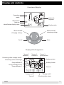
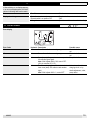
Display and controls
Overview of display
Operating
mode
Information
Adjuster
Hydraulic
diagram
SET
Identification display value
Display value
Menu controll
changing settings
Menu controll
changing settings
Enter
Cancel
Display with all segments
Sensor 1
collector 1
Sensor 4
collector 2
Diverting valve storage tank 2
Diverting valve exchanger
Pump collector 2
Pump storeage tank 2
Pump collector 1
Heating system
Auxillary heater
Sensor 4
SET
Storage tank 1
Sensor 2
A0805
Sensor 3
pump rehaet
Storage tank 2
Diverting valve return
3
Note:Display und Bedienelemente
4
A0805
1
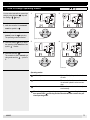
Operation
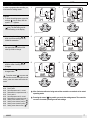
1.1 How to change operating modes
You can select automatic or manuel operating by using the enter
key and
the settings
keys.
1
2
Example:
1. when the controller is in automatic
mode the symbol is
.
2. To change the operating mode to
manual, press the
. enter key.
The operating mode now flashes.
3. Press the settings
key to select
the operating mode manual until the
symbol
flashes.
Automatic mode
3
4
4. Press the enter key
.
The controller is now in manual operating mode and the
symbol is
lit.
Manual
Operating modes:
Standby
• System off, only the protective functions
are activ
Automatic mode
• The controller functions are active do to
the selected hydraulic variant and settings
Manual
• The functions can be tested and adjusted manually
When changing operating modes you may press the
cancel key before you
have pressed the
enter key and the controller will then revert to the previous operating mode.
A0805
5
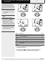
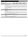
1.2 The information menu, operating data and temperature value
The information menu enables you to
look at information about the solar system. You can see actual temperatures,
and the way in wich the system is operating.
1
2
Example:
1. To enter the information menu, press
the settings
key until the symbol
appears.
2. To look at the data, press the enter
key.
A value flashes on the display.
3. By pressing the settings
key, the
temperature values and operating
data can seen in succession.
When the symbol SET appears on
the display the controller is indicating
the set point of the temprature value.
Information level
3
4
SET
4. When you look at the data you will
see the relevant part of the schematic flashing and it is corresponding
function setting flashing.
Display
SET
Description
Unit
Measured temperature value
°C
Set point of temperature
°C
Highest collector temperature in a 24 hour period
°C
Collector pump speed
%
Reheating pump relay, generator pump or diverter valve
-
Collector capacity
-
Collector yield
-
Information
-
After 2 minutes without a being entered the controller reverts back to
its actual operating mode.
Pressing the cancel
key anable you to exit the information menu.
The controller reverts to its actual operating mode and settings.
6
A0805
SET
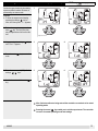
1.3 Programming the controller
In order to programm the controller you
must enter the settings menu.
1
Example:
1. To enter the settings menu, press the
settings
key so often, until the
symbol SET appears.
2
SET
SET
2. To view the settings, press the enter
key. The first setting and its
function flashing on the display.
Adjuster level
3. By pressing the settings
keys, the various settings can by
viewed in succession.
3
4. Press the enter
key to stay on to
the appropriate sub menu of the
value you wish to change.
5. By pressing the settings
keys the value of setting can be
changed.
6. Press the enter
changed value.
4
SET
5
SET
6
key to save the
SET
SET
Press the cancel
key once and
the controller reverts to the previous sub
menu, press once more and it exits the
menu.
The following adjusters are shown:
8-56
8-62
8-63
8-56
8-62
8-63
8-85
8-85
8-86
8-87
Priority tank1
Set temperature tank 1, normal
Diferentials for temperature tank 1
Priority tank 2
Set temperature tank 2, normal
Diferentials for temperature tank 2
Setting value collector pump 1 ( )
Setting value collector pump 2 ( )
Setting value circulation pump ( )
Setting value diverter valve ( )
A0805
After 2 minutes without a being entered the controller reverts back to its actual
operating mode.
Pressing the cancel
key anable you to exit the settings menu. The controller
reverts to its actual operating mode and settings.
7
SET
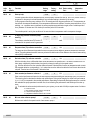
1.4 Making Basic Changes
Adjuster
HyFunction
draulic
8-62
all
Setting
range
Set temperature 1, normal
0÷90
Factory
setting
60
Unit Basic setting
Dat.:
Revised
Dat.:
°C
This anables you to set a set point temperature for the first circuit sensor. If the circuit is a hot water cylinder then
the maximum temperature will be set at the point at wich the sensor contact enters the cylinder. Ther thermal circuit
will only charge up to the value set here. Once this temperature is reached the thermal circuit will switch off, regardless of the solar energie available.
Basic target set value for calculation of the optimised over-increase of the number of revolutions during charging is set value.
8-63
all
Setting temperature differentials for
thermal circuit 1
1÷30
2
K
The temperature set in menu 8-62 above less the value set this menue provides a temperature at wich the solar
system will sart to heat the thermal circuit and commence heat exchange. Temperature within the differential do not
operate to send an instruction to start heating the circuit, If the differential is set to low, then the pump will frequentlyswitch on and off, reducing the overall efficiency of th system.
8-85
all
Setting value collector pump 1, in manual operation
In manual operation
8
0÷100
0
%
a setting can be entered here.
A0805
SET
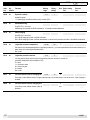
1.5 Changes that need an access code (expert level)
Certain changes should only be made by
experts and are therefore this menu is
protected by an access code.
1
Example:
1. To enter the expert menu keeping
pressing the settings
key so
often, until the symbol SET appears.
SET
2. To view the expert menu, press the
enter
key. The first intem that
may be adjusted and its function flashes.
3. Keep pressing the settings
until "Cod --" appears.
4. Press the enter
code.
key,
6. Confirm the code with the enter
key.
SET
Adjuster level
3
4
SET
SET
key to enter the
5. Enter the access code ("25") with the
keys.
settings
2
5
6
SET
SET
After 2 minutes without a being entered the controller reverts back to its actual
operating mode.
Pressing the cancel
key anable you to exit the expert menu. The controller
reverts to its actual operating mode and settings.
A0805
9
SET
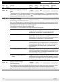
1.6 Adjuster code 1
Adjuster
HyFunction
draulic
04-06
all
Hydraulic variants
Setting
range
1÷1
Factory
setting
Unit Basic setting
Dat.:
1
-
16
-
Revised
Dat.:
Hydraulic variant
1 = Speed (rpm) controlled collector pump on tank (SP) 1
04-20
all
eBUS-Addressing
1÷16
Only ES 5911, not in use:
Addressing the controller in eBUS combination. 16 standard master addresses.
04-36
all
eBUS-charging
on/off
off
-
Only ES 5911, not in use:
On = eBUS charging by solar controller activated
Off = eBUS charging by solar controller deactivated, is carried out by another controller in the eBUS combination.
05-04
all
Legionella protection temperature
60÷80
60
°C
Set value for the thermal pasteurisation (Legionella protection). Tjis is the temperature at which heat treatment of a
water store as a contra legionella takes place.
Not in use!
05-14
all
Legionella protection function
0÷9
0
-
You may specify when and how often the legionella protection function is carried out.
(protective temperature as per Adjuster 5-04)
0 = never
1 = Once each week
8 = Once every day
9 = Always
Not in use!
08-01
all
Increase collector tank for charging ON
0÷50
15
K
If the temp. at the collector sensor is higher than the temp. on the tank sensor + set value "08-01" solar charging is
enabled.
08-02
all
Increase collector tank for charging OFF
0÷50
5
K
If the temp. at the collector sensor is less than the temp. at the tank sensor + set value "08-02", solar charging is
disabled.
10
A0805
SET
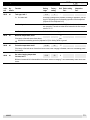
1.6 Adjuster code 1
Adjuster
HyFunction
draulic
08-15
all
Setting
range
Start-up help
on/off
Factory
setting
on
Unit Basic setting
Dat.:
Adaptation
Dat.:
-
In some systems the collector temperature may not be properly recorded on start up. In the "on" position a sart up
programm for the pump is activated enabling a very accurate reading to be taken by the sensor.
In this programm the solar pump switches on for 30 seconds and then the pump switches off. The temperature at
the collector is measured immediately. If the temperature difference is sufficient, the solar pump switches on. If the
swithing - on - conditions are not reached, the solar pump becomes switched on again, after a variable period of
time ( between 15 minutes and 100 minutes) for another period of 30 seconds.
The variable period is set by the conditions of the actual collector temperature and the temperture changes.
08-20
all
P range (Xp) collector controller pump
steering
10÷50
20
K
The collector controller has a PID control. The set P range determines at which set value deviation 100% adjusting
command for the speed control is generated.
08-21
all
Response time (Tn) collector controllers
0÷30
10
min
The response time influences the speed with which the speed control adjusts a deviation between set and actual
values. The setting determines after how many minutes the double value of the difference from the minimum setting
value (08-35) is demanded.
08-22
all
Derivative time (Tv) collector controller
0÷10
0
min
With the derivative time, a differential share can be allocated to the speed control. The actual increase of the collector temp. multiplied by the derivative time gives the change in setting for the speed control.
With the derivative time, the controller makes a forecast of the deviation from the set temperature and corrects
the expected deviation correspondingly, i.e. it makes the correction before the deviation from the set value has developed. Time horizon of the forecast = derivative time.
08-30
all
Solar nominal performance collector 1
1÷50
8
kW
Solar nominal performance is based on the actuel panel performance taking the flow settinge (08-37) into account.
This value is used to calculate the relative solar performance. During solar charging the actual solar performance
(n x c x V x dT) is compared to the nominal performance. Depending on the actual panel performance the controller
will modulate the pump speed and controller flow, thus increasing the performance and efficiencyof the solar system.
To calculate the solar nominal performance in your system, you can take 0.6 kW per square meter of collector.
Note:
08-35
all
n = actual set value
c = heat capacity medium collector circuit (8-09)
V = volume at 100% speed (8-37)
T = temperature difference collector B1 / tank B2
Min. set value collector pump 1
5÷100
50
%
Minimum set value for the speed control of the collector pump 1
A0805
11
SET
1.6 Adjuster code 1
Adjuster
HyFunction
draulic
08-37
all
Volume flow coll. pump 1 at 100% set
value
Setting
range
1÷50
Factory
setting
2
Unit Basic setting
Dat.:
Adaptation
Dat.:
l/min
The volume flow at 100% set value of the pump collector 1 and aligned hydraulic.
To calculate the volume flow
in your system, you can take 1 l/min per collector.
In manual operating mode set Adjuster 8-85 to 100%. Read
the through-flow at the floating body volume flow meter.
08-50
all
Strategy solar charging
0÷4
3
-
A basic strategy can be selected for solar charging:
Note: In the charging strategy it is attempted to charge the tank to the required set or maximum value with as few
charging cycles as possible. Based on the available solar energy, the controller attempts to maintain an even increase at the collector sensor throughout the whole charging time.
This optimised increase has a lower limit (Adjuster 8-64).
In the strategies 3 + 4 this calculation is only used with high solar energy levels.
08-51
all
0 = Parallel charging
Charging in an alternating operation, the lowest tank is charged first.
The set value for the speed control is determined from the
temperature at the tank sensor + increase (Adjuster 8-64)
1 = Set charging
Charging is carried out to the set value according to priority of the tank
(Adjuster 8-56). The tank with priority 1 is charged first to the set value
(Adjuster 8-62). The set value for the speed control is determined from
the temperature at the tank sensor + optimised increase.
2 = Maximum charging
Charging is carried out to the maximum value according to priority of
the tank (Adjuster 8-56). The tank with priority 1 is charged first up to
the maximum value (Adjuster 8-59). The set value for the speed control is determined by the maximum value + optimised increase
(Adjuster 8-64)
3 = Set charging dependent on energy
Charging is carried out to the set value according to energy available
(Adjuster 8-51) parallel in alternating operation or according to priority
of the tank (Adjuster 8-56). The set value for the speed control is determined according to the active strategy.
4 = Maximum charging dependent on
energy
Charging is carried out to the maximum value according to the energy
available (Adjuster 8-51) parallel in alternating operation or according
to priority of the tank (Adjuster 8-56). The set value for the speed control is determined according to the active strategy.
Change-over solar charging
(high energy levels)
30÷100
50
%
If the comparison of actual solar energy with the nominal performance gives a factor which lies above the setting
value, a change-over from parallel operation (alternating) to set value or maximum charging takes place.
The basic settings for the nominal solar performance (E8-30) are directly linked and must be correctly set.
12
A0805
SET
1.6 Adjuster code 1
Adjuster
HyFunction
draulic
08-55
all
08-59
all
Tank type, tank 1
Setting
range
0÷4
Factory
setting
0
Unit Basic setting
Dat.:
Adaptation
Dat.:
-
0 = Hot water tank
All charging strategies are possible. According to application, the settings for the change-over to alternating operation must be adjusted.
(Adjuster 8-65 and Adjuster 8-66)
2 = Heating tank
If the tank set value is set below 20°C, this is understood to be summer operation. The tank set value will be lowered to the frost temperature of 10 °C.
4 = Swimming pool
Not included in alternating operation
Maximum temperature, tank 1
10÷90
80
°C
If the temp. at the tank sensor rises above the set value, solar charging for this tank is disabled.
With active overheating protection (Adjuster 8-05) this limiting value is ignored.
08-60
all
Protective temperature tank 1
10÷95
90
°C
If the temp. at the tank sensor rises above the set value, solar charging is disabled, even if the overheating protection is active.
08-64
all
Set value charging temperature
increase, tank 1
5÷50
20
K
Minimum increase which is demanded at the collector sensor for charging. This increase always refers to the tank
sensor.
A0805
13
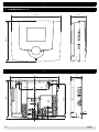
2
Dimensions and assembly
2.1 Dimensions DC 12
48.7
135.3
153.5
2.2 Dimensions of the basic housing DC 12
36
8
8.5
108
44
48
128
2.5
149
9.3
0.8
14
A0805
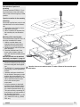
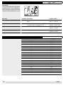
2.3 Assembly DC 12
Determination of position of
mounting
The solar controller ES 5910/11 S is to
be placed closely at the solar heating
circle, so that a short wiring way is made
possible.
Open the controller for the assembly
and wiring
So that the controller base can be installed and wired, first it must be dismounted.
1. Loosen the screw of the front cover.
2. Take off the front cover.
3. With a screwdriver lift the base from
the controller-print, see illustration
right.
Reset button
Mounting of the controller base
The controller base of the ES 5910/11 S
has to be mounted with 3 screws.
1. Hold the controller base to the
assembly place and mark with an
indication pin the mounting holes.
2. Drill the mounting holes and provide
them with pegs.
3. Place the controller base, fit the
screws (do not tighten), align the
base, then drive the mounting screws
fully home.
Now the controller can be attached
electrically, see chapter 3.1, page 16.
Installation and set-up instructions
• Electrical installation and fuse protection must comply with local regulations.
Open the front cover to make a restart. To make a Restart of the controller push
• The ES 5910/11 S must be powered
the reset button.
continuously, to ensure operation at
all times.
• Upstream switchgear should therefore be limited to emergency or main
switches that are permanently "on".
• Before putting the controller into operation, check all electrical connections to the various system
components.
• It may be necessary to electrically
suppress strongly inductive loads in
the vicinity of the controller (contactors, solenoid-operated valves, etc.).
This can be done by connecting RC
circuit directly to the coil terminals of
the disturbing components.
Recommended RC circuit: 0.047ƒÊF,
100., rated at 250 VAC (e.g. Bosch,
RIFA, etc.).
A0805
15
3
Start up
The connections main voltage on the left side No. 1-3/LN are
loaded with 230 V. These clamps may
be affected only dead, otherwise mortal danger exists because of current
impact.
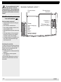
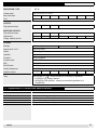
Example: Hydraulic variant 1
Connections
net
Connections
sensors
T
T
B2
Pump
solar charging
Not
used
Not
used
Voltage supply
230 V / 50 Hz
Collektor 1
sensor 1
Storage tank 1
sensor 2 bottom
B1
Check up before start up if:
• the plant-main-switch (if existing) is
switched on!
• the controller is switched on!
• the correctly hydraulic variant is selected (Adjuster 4-06)
• the temperature set points values are
o.k.!
• the temperatures of the connected
sensors are shown on the display,
and there values are plausibly!
• a charge enterprise is possible do to
the collector temperature/storage
tank temperature!
L N N 1 2 N N 3
3.1 Electrical connection allocation
Checking the controller
In order to test the controller and the appropriate mechanism, the following clarifications can be accomplished after
switching on the DC 12:
1. All the segments are displayed briefly
(page 3)
1. The software number appears
(p. e. SW 1.4)
If the controller display then reverts to
normal, the internal function test was
successful.
16
A0805
SET
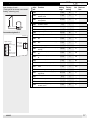
Solar charging of tank 1.
(Tank type can be chosen, warm water/
heating / swimming pool)
8-62
B2
Connections hydraulic 1:
Sensors
A0805
Factory
setting
Unit Basic set.
Dat.:
0÷90
60
°C
Setting temperature differentials for
thermal circuit1
1÷30
2
K
8-85
Setting value collector pump 1, in manual operation
0÷100
0
%
4-06
Hydraulic variants
1÷9
1
-
4-20
Addressing of eBUS
1÷16
16
-
4-36
eBUS charging
on/off
off
-
5-04
Legionella protection temperature
60÷80
60
°C
5-14
Legionella protection function
0÷9
0
-
8-01
Increase collector tank for charging
ON
0÷50
15
K
8-02
Increase collector tank for charging
OFF
0÷50
5
K
8-15
Start-up help pipe collector
on/off
on
-
8-20
P range (Xp) collector controller pump
steering
10÷50
20
K
8-21
Response time (Tn) collector controllers
0÷30
10
min
8-22
Derivative time (Tv) collector controller
0÷10
0
min
8-30
Solar nominal performance collector 1
1÷50
8
kW
8-35
Min. set value collector pump 1
5÷100
50
%
8-37
Volume flow coll. pump 1 at 100% set
value
1÷50
2
l/min
8-50
Basic strategy solar charging
0÷4
3
-
8-51
Change-over solar charging (high energy levels)
30÷100
50
%
8-55
Tank type, tank 1
0÷4
0
-
8-59
Maximum temperature, tank 1
10÷90
80
°C
8-60
Protective temperature tank 1
10÷95
90
°C
8-64
Set value charging temperature
increase, tank 1
5÷50
20
K
T
Not
used
Voltage supply
230 V / 50 Hz
Setting
range
Set temperature tank 1, normal
T
L N N 1 2 N N 3
B2
Collector 1
sensor
Pump
solar charging
Storage tank 1
Not
sensor bottom
used
B1
High voltage
Adju- Function
ster
- 8-63
B1
3
Code
3.2 Hydraulic variant 1
1
17
SET
3.3 Adjuster code 2
The adjusters with code 2 are
valid for all hydraulic variants!
You receive the code 2 from
your heating expert.
Adjuster
Function
8-05
Overheating protection
on/off
on
If the temperature at the collector rises above the set collector maximum temperature (Adjuster 8-11) with the overheating protection active, solar charging will
be enabled independent of the set tank maximum temperature (Adjuster 8-59).
The set value for the speed control is determined by the temperature on the tank
sensor + setting value 8-64.
If the collector protection temperature Adjuster 8-10 or the tank protective
temperature (E8-60) is exceeded, solar charging is disabled.
8-09
Factory
setting
Unit Basic set.
Dat.:
Special heat capacity collector
kJ/
on/off
4.1
fluid
kg K
Special heat capacity of the collector fluid according to manufacturer’s
specifications.
8-10
Collector protective temperature 80÷130
130
°C
If the temperature at the collector sensor rises above the set value, solar charging is disabled.
8-11
Collector maximum temperature 80÷130
95
°C
If the temperature at the collector sensor rises above the set values with the
overheating protection active (Adjuster 8-05), solar charging is enabled.
8-13
Frost protection function
-50÷10
-50
°C
Deactivated if the setting is -50°C.
Solar pump is switched on if the temperature at the collector sensor < setting hysteresis.
Hysteresis 3 K is a given set value.
8-90
8-91
8-92
18
Setting
range
Error threshold for pump feed0÷200
100
%
back signal
The pump can be controlled. The controller measures the phase displacement
and compares it to the expected values.
Only for controller ES 5910 P / 5911 P. Error check is only carried out at
pump start-up.
0%
= Only small deviations allowed
0 ÷ 199%
= The larger the set value, the higher the allowed deviation
200%
= Inactive, no pump error messages
Max. temperature difference
10÷80
50
K
collector - tank
If the difference in temperature between the collector and the tank temperature
rises above the set value when solar charging is active during the set time
(Adjuster 8-92), an error message (Err 61, 62, 63) is generated.
Waiting period error message
0÷180
30
min
∆T collector - tank
If the difference in temperature between the collector and the tank temperature
is too high when solar charging is active and during the set time, the error message is generated according to 8-91.
0 = Error message disabled
A0805
4
Troubleshooting
If after switching on, no display appears,
or an error message appears, the clarifications in following table can be useful.
Statement
Display doesn’t appear
Possible cause
Controller not under tension
External switch is on position "Off"
Wiring defect
Solution
Examine the fuse, set external switch to
"ON"!
Open the controller and examine the wiring!
4.1 Error codes
Error-display
Error Code
41
Hydraulic Description
all
Sensor 1 outside the measuring range.
42
all
53
all
61
all
A0805
Possible cause
Short circuit of sensor / cut
out
Sensor 2 outside the measuring range.
Short circuit of sensor / cut
out
Speed (revs.) of the pump does not correspond to Pump blocked!
the controller given figure.
Note: With Adjuster 8-90 = 200, control OFF.
(Only in controller DC 12 P)
Error when charging from collector 1 to tank 1
No heat transfer, air in
charging circuit, no hylower zone (temp. diff. collector–tank remains
draulic adjustment, outlet,
high)
Note: With Adjuster 8-92 = 0, control OFF
pump defect
19
4.2 Information about the plausibility check
Info-display
The controller checks the system status
and signals errors. This is a plausibility
check of the data and serves to provide
information when malfunctioning occurs.
Info code
Hydraulic Description
101
all
Collector max. temp. > as the collector protection Wrong basic settings
temp.
(A 8-11) > (A 8-10)
Possible cause
102
all
Increase collector tank for charging OFF > increa- Wrong basic settings
se collector tank for charging ON– 2K
(A 8-02) > (A 8-01 - 2K)
105
all
Set temp. tank 1 normal > max. temp. tank 1
107
all
Maximum temp. tank 1 > protection temp. tank 1 Wrong basic settings
(A 8-59) > (A 8-60)
Wrong basic settings SP 1
(A 8-62) > (A 8-59)
4.3 Temperature sensor resistance
Temperature °C
-20
-15
-10
-5
0
5
10
15
20
25
30
40
50
60
70
80
90
100
105
110
115
20
Resistance NTC 5 kΩ
48'535
36’475
27’665
21’165
16’325
12’695
9’950
7’855
6’245
5’000
4’029
2’663
1’802
1’244
876
628
458
339
294
255
223
A0805
5
Technical data
DESIGNATION / TYPE
DC 12
Voltage supply
230 V AC ± 10% 50 – 60 HZ
Max. power input
2.3 VA
Fuse
3.15 A
OUTLETS
Fully electronic relays
1
SWITCHING CAPACITY
Fully electronic relays
1 (1) A
Inputs sensor
2
Voltage, measuring circuit
12 V, V, protective insulation 4 kV
HOUSING
Montage
Wall mounting
Dimensions H / W / D
153.5x135.3x48.7
Display
LCD 96 Segment display
Operation
4 push buttons
Protection
IP 40 – EN 60529
Protective class
II – EN 60730
EMV
EN 50082-1
EMV-Emission
EN 50081-1
Ambient temperature
0 … 50°C
Hydraulic variants
Tests
1
The controller is
- conform according to the following EU guidelines:
• 70/23/EWG "Low Voltage-Guideline"
• 89/336/EWG "EMC guideline", including the amendment guidelines up to
90/68/EWG
5.1 Explanation of terms and abbreviations
h
Actual value
K
min
Set point value
A0805
Hours
Measured value/temperature by sensor, displayed on controller.
Kelvin, temperature difference
Minutes
Temperature witch is to reach by the controller
21
Note:
22
A0805
6
Index
A
Adjuster code 1 ............................................................................................................................................10
Adjuster code 2 ............................................................................................................................................18
Adjuster with access code (expert level) ........................................................................................................9
Adjuster without code .....................................................................................................................................8
Assembly ......................................................................................................................................................15
C
Change operating mode .................................................................................................................................5
D
Dimensions ..................................................................................................................................................14
E
Electrical connection allocation ....................................................................................................................16
Error codes ...................................................................................................................................................19
Explanation of terms and abbreviations .......................................................................................................21
H
Hydraulic variant ..........................................................................................................................................17
I
Information about the plausibility check .......................................................................................................20
O
Operation .......................................................................................................................................................5
Q
Query of temperatures and operating data ....................................................................................................6
S
Start up .........................................................................................................................................................16
T
Technical data ..............................................................................................................................................21
Temperature sensor resistance.....................................................................................................................20
Troubleshooting ...........................................................................................................................................19
A0805
23
Manufacture or distribution:
Specially manufactured for Genersys Plc
Genersys Plc,
37 Queen Anne Street
London
W1W 9JB
Phone: 020 637 0901
Fax: 020 637 0908
Web: http://www.genersys.com
[email protected]
A0805