1
SNC-C7478
36x Network Smart Dome Camera
User Manual
imagine the possibilities
Thank you for purchasing this Samsung product.
To receive more complete service,
please visit our website.
www.samsungsecurity.com
safety information
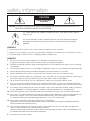
CAUTION
RISK OF ELECTRIC SHOCK.
DO NOT OPEN
CAUTION: TO REDUCE THE RISK OF ELECTRIC SHOCK, DO NOT REMOVE COVER (OR BACK) NO USER SERVICEABLE PARTS
INSIDE. REFER SERVICING TO QUALIFIED SERVICE PERSONNEL.
This symbol indicates that dangerous voltage consisting a risk of electric shock is present
within this unit.
This exclamation point symbol is intended to alert the user to the presence of important
operating and maintenance (servicing) instructions in the literature accompanying the
appliance.
WARNING
• To reduce the risk of fire or electric shock, do not expose this appliance to rain or moisture.
• To prevent injury, this apparatus must be securely attached to the floor/wall in accordance with the installation instructions.
• If this power supply is used at 24V AC, a suitable plug adapter should be used.
WARNING
1.
Be sure to use only the standard adapter that is specified in the specification sheet.
Using any other adapter could cause fire, electrical shock, or damage to the product.
2.
Incorrectly connecting the power supply or replacing battery may cause explosion, fire, electric shock, or damage
to the product.
3.
Do not connect multiple cameras to a single adapter. Exceeding the capacity may cause abnormal heat generation or fire.
4.
Securely plug the power cord into the power receptacle. Insecure connection may cause fire.
5.
When installing the camera, fasten it securely and firmly. The fall of camera may cause personal injury.
6.
Do not place conductive objects (e.g. screwdrivers, coins, metal parts, etc.) or containers filled with water on top of
the camera. Doing so may cause personal injury due to fire, electric shock, or falling objects.
7.
Do not install the unit in humid, dusty, or sooty locations. Doing so may cause fire or electric shock.
8.
If any unusual smells or smoke come from the unit, stop using the product. In such case, immediately disconnect
the power source and contact the service center. Continued use in such a condition may cause fire or electric shock.
9.
If this product fails to operate normally, contact the nearest service center. Never disassemble or modify this product in
any way. (SAMSUNG is not liable for problems caused by unauthorized modifications or attempted repair.)
10. When cleaning, do not spray water directly onto parts of the product. Doing so may cause fire or electric shock
11. If the camera is installed or rebooted after power failure when ambient temperature is below the freezing point, the
dome cover is frosted. In this case, the frost will be disappeared after 3 hours after turning on the power.
(It is noted that lowest guaranteed operating temperature is -45ºC(-49ºF) without wind.).
12. Do not expose the product to the direct airflow from an air conditioner.
Otherwise, it may cause moisture condensation inside the Clear Dome due to temperature difference between
internal and external of the dome camera.
13. If you install this product in a low-temp area such as inside a cold store, you must seal up the wiring pipe with
silicon, so that the external air can not flow inside the housing.
Otherwise, external high, humid air may flow inside the housing, pooling moisture or vapor inside the product due
to a difference between internal and external temperature.
2 – 36x Network Smart Dome Camera
safety information
CAUTION
1. Do not drop objects on the product or apply strong blows to it. Keep away from a location subject to excessive
vibration or magnetic interference.
2. Do not install in a location subject to high temperature (over 140°F), low temperature (below -49°F), or high humidity.
Doing so may cause fire or electric shock.
3. If you want to relocate the already installed product, be sure to turn off the power and then move or reinstall it.
4. Remove the power plug from the outlet when there is a lighting storm. Neglecting to do so may cause fire or
damage to the product.
5. Keep out of direct sunlight and heat radiation sources. It may cause fire.
6. Install it in a place with good ventilation.
7. Avoid aiming the camera directly towards extremely bright objects such as sun, as this may damage the CCD image
sensor.
8. Apparatus shall not be exposed to dripping or splashing and no objects filled with liquids, such as vases, shall be
placed on the apparatus.
9. The Mains plug is used as a disconnect device and shall stay readily operable at any time.
FCC Statement
This device complies with part 15 of the FCC Rules. Operation is subject to the following two conditions :
1) This device may not cause harmful interference, and
2) This device must accept any interference received including interference that may cause undesired operation.
Caution
This equipment has been tested and found to comply with the limits for a Class A digital device, pursuant to part 15 of FCC Rules.
These limits are designed to provide reasonable protection against harmful interference when the equipment is operated in a commercial environment.
This equipment generates, uses, and can radiate radio frequency energy and, if not installed and used in accordance with the
instruction manual, may cause harmful interference to radio communications. Operation of this equipment in a residential area is
likely to cause harmful interference in which case the user will be required to correct the interference at his own expense.
IC Compliance Notice
This Class A digital apparatus meets all requirements of the Canadian Interference.-Causing Equipment
Regulations of ICES-003.
English – 3
important safety instructions
1.
Read these instructions.
2.
Keep these instructions.
3.
Heed all warnings.
4.
Follow all instructions.
5.
Do not use this apparatus near water.
6.
Clean only with dry cloth.
7.
Do not block any ventilation openings. Install in accordance with the manufacturer’s instructions.
8.
Do not install near any heat sources such as radiators, heat registers, or other apparatus (including amplifiers) that
produce heat.
9.
Do not defeat the safety purpose of the polarized or grounding-type plug. A polarized plug has two blades with
one wider than the other. A grounding type plug has two blades and a third grounding prong. The wide blade or
the third prong is provided for your safety. If the provided plug does not fit into your outlet, consult an electrician for
replacement of the obsolete outlet.
10. Protect the power cord from being walked on or pinched particularly at plugs, convenience
receptacles, and the point where they exit from the apparatus.
11. Only use attachments/accessories specified by the manufacturer.
12. Use only with cart, stand, tripod, bracket, or table specified by the manufacturer, or sold with
the apparatus.
13. Unplug this apparatus when a card is used. Use caution when moving the cart/ apparatus
combination to avoid injury from tip-over.
14. Refer all servicing to qualified service personnel. Servicing is required when the apparatus has been damaged
in any way, such as powersupply cord or plug is damaged, liquid has been spilled or objects have fallen into the
apparatus, the apparatus has been exposed to rain or moisture, does not operate normally, or has been dropped.
Apparatus shall not be exposed to dripping or splashing and no objects filled with
liquids, such as vases, shall be placed on the apparatus
4 – 36x Network Smart Dome Camera
contents
Introduction
Features
Recommended PC Specifications
Compatible IP Routers
Product & Accessories
Parts Name & Functions
7
8
8
9
10
Installation
DIP Switch Setup
Installation Using Pole Mount Bracket
Cabling
Inserting/Removing an micro SDHC Memory Card
Memory Card Information (not included)
11
12
15
17
18
Operation
Check points before operation
Preset and Pattern Function Pre-Check
Auto Calibration
Starting OSD Menu
Reserved Preset
Preset
Auto Pan
Pattern
Scan
Schedule
Other Functions
OSD Display of Main Screen
General Rules of Key Operation for Menu
19
19
19
19
19
20
20
20
21
21
21
22
22
How to use OSD Menu
Structure of the Setup Menu
Main Menu
System Information
Display Setup
Privacy Zone Mask Setup
Motion Setup
Function Setup
Preset Setup
Auto Pan Setup
Pattern Setup
Scan Setup
Schedule Setup
Camera Setup
System Setup
System Initialize
23
25
25
25
25
26
27
28
29
29
30
32
33
34
36
Network Connection & Setup
Connecting the camera to an IP router with the xDSL/Cable modem
Connecting the camera to an IP router with local area networking
Connecting the camera directly to a DHCP-based xDSL/Cable modem
37
39
41
English – 5
contents
Connecting the Camera Directly to Local Area Networking
Searching for the Camera
42
43
Setting Static IP
Manual Network Setting
Automatic Network Setting
44
46
Setting Dynamic IP
Dynamic IP Setting
Port Forwarding (Port Mapping) Setting
47
47
Using the Camera
Connecting to the Camera
Installing ActiveX
48
49
Web Viewer
Main Screen
Using the Camera
Using the SD Search Viewer Screen
51
52
54
Setup Tool
Setting the camera
Video & Audio Configuration
IP
User
Language
Digital Image Stabilizer
Date/Time
Log
Software Update
Reset
HTTPS
Transfer Setup
Record Setup
Alarm Image Setup
Alarm Input Setup
Motion
Schedule
Streaming Setup
DDNS
SNMP
55
56
57
58
58
58
59
59
59
60
60
60
61
62
62
63
64
64
65
66
Appendix
Troubleshooting
Specifications
Dimension
6 – 36x Network Smart Dome Camera
67
69
71
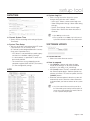
introduction
FEATURES
❖ Network Specifications
• Powerful Dual Stream by using DSP based
MPEG4, MJPEG compression
• Superior Video Quality and System Stability.
• High speed : Up to 30 fps at 720x480, 25 fps at
720x576.
• Web Browser based viewer support.
• Remote Pan/Tilt/Zoom control.
• Bidirectional Audio support.
• Support with DDNS Service (Samsung DDNS,
Public DDNS) for Dynamic IP.
• Various protocol support. (ARP, HTTP, HTTPS,
DHCP, TCP/IP, UDP, RTP/RTSP, SMTP, FTP,
SNMP, etc)
• IPv4/IPv6 support.
• Alarm Function
• Motion Detection Function
• Micro SD Card Backup
❖ Camera Specifications
• CCD Sensor : 1/4" Interline Transfer CCD
• Zoom Magnification : × 36 Optical Zoom, × 12
Digital Zoom (Max × 432 Zoom)
• Day & Night Function : ICR (IR Cut filter Removal)
• Various Focus Mode : Auto Focus / Manual Focus /
ONEAF Focus.
• Independent or Global camera settings for each
Preset locations.
❖ Powerful Pan/Tilt Functions
• Max. 360°/sec high speed Pan/Tilt Motion
• Using Vector Drive Technology, Pan/Tilt motions are
accomplished in the shortest path. As a result, time
to target view is reduced dramatically and the video
on the monitor is very natural to watch.
• Ultra low speed (0.05°/sec) enables operator to
locate camera to desired target view with accuracy
and ease.
• Zoom-proportional pan/tilt speed helps operator to
move the camera easily.
❖ Preset, Pattern, Auto Pan, Scan, Privacy
Mask, Schedule and More…
• Max. 127 Presets are assignable. All of them have
independent characteristics such as White Balance,
Auto Exposure, Label, Alarm Input/Output and so
on.
• Max. 8 set of Auto Pan can be stored. This enables
to move camera repetitively between two preset
positions with designated speed.
• Max. 4 of Patterns can be recorded and played back.
This enables to move camera to follow any trajectory
operated by joystick as closely as possible.
• Max. 8 set of Scan action can be stored.
This enables to move camera repetitively with
combination of Preset or Pattern or Auto Pan.
A Scan is composed of max. 20 entities of Preset/
Pattern/Auto Pans.
• Max 8 Privacy Masks can be set up to protect
privacy of other people.
• 7 rules of Schedule can be assigned by day and
time. Appropriate actions (such as Home, Preset,
Scan, Pattern and Auto Pan) can be defined for
each rule. Also, it is possible to use Weekday and
All days to simplify the rule.
❖ PTZ(Pan/Tilt/Zoom) Control
• With RS-485 communication, max. 255 of cameras
can be controlled at the same time.
❖ OSD(On Screen Display) Menu
• OSD menu is provided to display the status of
camera and to configure the functions interactively.
• Currently, 7 Languages are supported for
OSD Menu: [ENGLISH/ESPAÑOL/FRANÇAIS/
DEUTSCH/ITALIANO/РУССКИЙ/PORTUGUÊS]
• The information such as Camera ID, Pan/Tilt/Zoom/
Direction, Alarm Input & Output, date/time and
Preset can be displayed on screen.
• Each display item can be turned on or off
independently.
❖ Alarm I/O Functions
• 8 alarm sensor Inputs and 4 relay output are
available.
• To reject external electric noise and shock perfectly,
alarm sensor Input is decoupled with photo
coupler.
• If an external sensor is activated, camera can be
set to move to the corresponding Preset position.
• Relay outputs can be assigned to work with a
certain preset.
❖ Reserved Presets for Special Purpose
• Most of camera settings are directly changed by
calling Reserved Presets, not entering into OSD
menu. For more information, refer to “Reserved
Preset” (page 19) in this manual.
English – 7
introduction
RECOMMENDED PC
SPECIFICATIONS
• CPU : Pentium4/2.4GHz or higher
• Operating System : Windows XP(Service Pack 2) /
Windows Vista
• Resolution : 1024x768 pixels or higher
• RAM : 512MB or higher
• Web Browser : Internet Explorer 6.0 or higher
• Video Card : Radeon, Nvidia
• Video Memory : 128MB
• DirectX 8.1 or higher
COMPATIBLE IP ROUTERS
• Linksys
• D-Link
• Netgear
8 – 36x Network Smart Dome Camera
introduction
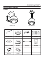
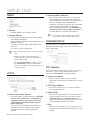
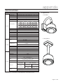
PRODUCT & ACCESSORIES
❖ Product
Wall Mount Type
Ceiling Mount Type
❖ Accessories
Hexagonal wrench
Water proof tape
User Manual / IP Installer CD
Quick Guide
Cross Cable
Core Filter
Housing Safety Cable Hanger Screw & Plastic Anchor (4pcs)
Safety Cable
Hole Template
English – 9
introduction
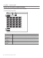
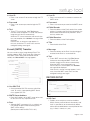
PARTS NAME & FUNCTIONS
SUN SHIELD & UPPER
HOUSING
PTZ MECHANISM
DOME SAFETY CABLE
NETWORK BOX
FAN & HEATER CABLE
FAN
HOUSING SAFETY CABLE HANGER
HEATER
DOME COVER
• Dome Cover
Do not detach protection vinyl from dome cover
before finishing all installation process to protect dome
cover from scratches or dust.
In the dome cover, there are Fan and Heater to
remove moisture.
• Sunshield & Upper housing
Sunshield protect bubble dome cover from the sun
rays and rain fall from. In the sunshield, there is the
upper housing which will contain accommodate
PTZ mechanism. Also, the upper housing will be
connected to both mounting brackets and dome
cover.
10 – 36x Network Smart Dome Camera
• Wall/Ceiling mount Bracket
These are used to install the camera on the wall or
ceiling and have Network box in them.
• Network Box
The network box has many important roles of
connection between Dome camera and outside. Top
of Network box, there are dip switches and terminal
blocks for Power supply, Audio In/Out, Video Output,
RJ-45 Ethernet port, Alarm Input/output.
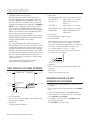
Installation
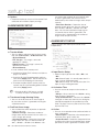
❖ Communication Protocol Setup
DIP SWITCH SETUP
Before you install the camera, you should set the DIP
switches to configure the camera ID, Baud rate and
communication protocol.
ON
ON
1
Protocol
w
WWWGaGhGw
0x00
: Auto Protocol
0x03
: SAMSUNG
WWZGaGzhtz|un
Baud
Rate
iGy
0x00 : 2400
WWWGaGY[WW
0x01
: 4800
WWXGaG[_WW
0x02
: 9600
WWYGaG`]WW
0x03
: 19200
WWZGaGX`YWW
0x04
: 38400
WW[GaGZ_[WW
5
6
7
8
Protocol
Pin1
Pin2
Pin3
Pin4
OFF
OFF
OFF
OFF
Auto Protocol
ON
ON
OFF
OFF
SAMSUNG
• If you set the protocol as Auto Protocol, camera will
automatically recognize the kind of Protocol.
• If you want to control using DVR or system
keyboard, their protocol must be identical to
camera. Otherwise, you can not control the
camera.
• If you changed camera protocol by changing DIP
S/W, the change will be effective after you reboot
the camera.
❖ Camera ID Setup
• Factory default of protocol is “Auto” Protocol.
❖ Communication Baud rate Setup
ON
2
3
4
5
6
7
ON
8
• ID number of camera is set using binary number.
The example is shown bellow.
Pin
1
2
3
4
5
6
7
ID Value
1
2
4
8
16
32
64 128
ex) ID=5
4
Switch State
ID Setting (1~255)
pkGzGOX¥Y\\P
1
3
• Select the appropriate Protocol with DIP switch
combination.
RS-485
yzT[_\
Terminate
{
ON
2
8
ON
1
2
3
4
5
6
7
8
• Select the appropriate Baud rate with DIP switch
combination.
Switch State
Protocol
ON OFF ON OFF OFF OFF OFF OFF
Pin5
Pin6
Pin7
ex) ID=10 OFF ON OFF ON OFF OFF OFF OFF
OFF
OFF
OFF
2400 BPS
ON
OFF
OFF
4800 BPS
• The range of ID is 0~255. Factory default of
Camera ID is 1.
OFF
ON
OFF
9600 BPS
ON
ON
OFF
19200 BPS
• If you want to control a certain camera, you must
match the camera ID with Cam ID setting of DVR or
Controller.
OFF
OFF
ON
38400 BPS
• Factory default of Baud rate is “9600 BPS”
English – 11
installation
❖ RS-485 Termination Resistor
ON
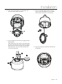
3. After locating the wall mount bracket on the
anchor bolts properly. Tighten the nuts for anchor
bolts
ON
1
2
3
4
5
6
7
8
• Pin 8 is used for ON/OFF of RS-485 Termination.
Normally, it must be OFF state. Especially when you
have trouble with long Daisy chain style connection,
turn ON this termination switch of last camera.
– Pin 8 : RS-485 Termination Resistor (ON/OFF)
INSTALLATION USING POLE
MOUNT BRACKET
1. Using the paper template, mark the holes on the
wall.
4. Connect cables to terminal blocks and BNC in the
Network box. See the cabling in the next section.
2. After drilling the holes, fix the four anchor bolts
into the holes.
12 – 36x Network Smart Dome Camera
installation
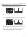
5. Press the PTZ mechanism's A, B handles and
pull out for Main Cable connection.
7. Care must be taken dome cover is hung by
internal safety cable properly. Plug fan/heater
cables into the connectors in the housing.
A
B
6. Wrap the pipe thread of the housing top by Water
proof tape [1].
After hooking the safety cable on the hole of pipe
[2], attach the upper housing to mount bracket by
turning it at least seven turns [3]. To fix the upper
body orientation, turn the handle of double nuts
to clockwise tightly [4].
8. Plug the connector of cable from network box
into properly.
2
1
4
3
English – 13
installation
9. After checking the orientation of one touch
connector in the upper housing, press the PTZ
mechanism into hook in the upper housing.
11. Close the dome cover. Care must be taken to
locate dome cover by matching the “Arrow”
mark.
ٻ
ٻ
ٻ
ٻ
ٻ
ٻ
G
12. Tighten four screws on the dome cover in
sequence as shown in the picture bellow.
10. To lock the PTZ mechanism to the upper
housing, press the two black handles till it sounds
snap.
ٻ
ٻ
4
ٻ
1
ٻ
ٻ
ٻ
2
3
G
To maintain the best sealing, the torque of each screw
must be in the range between 0.5 ~ 1.0 N·m
(0.37 ~ 0.73 lbf·ft).
14 – 36x Network Smart Dome Camera
installation
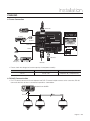
CABLING
❖ Power Connection
Main Cable
ALARM OUTPUT
Pre-Amp
1
2
3
4
ALARM INPUT
Speaker
Audio Out
1 2 3 4 G 5 6 7 8
AC 24V
Audio In
R INK CT
ET
A
ES PW L
R
AC 24V
POWER
Power
AUDIO
IN
OUT
F.G.
BNC Video
Microphone
Pre-Amp
LAN Cable
• Please, check the voltage and current capacity of rated power carefully.
Rated Power
Input Voltage Range
Current Consumption
AC 24V
AC 19V ~29V
23W(Heater Off) / 55W(Heater On)
❖ RS-485 Communication
• For PTZ control, connect this line to keyboard and DVR. To control multiple cameras at the same time, RS-485
communication lines of them is connected in parallel as shown below.
Keyboard Controller/DVR
RS-485
English – 15
installation
❖ Video Connection
• Connect with BNC coaxial cable.
❖ Audio Input/Ouput Connection
1. Connect the AUDIO IN port of the camera with the microphone directly or LINE OUT port of the amplifier that
the microphone is connected to direct Mic Connection: Set Audio Input Gain high (10). Refer to page 56 in this
Manual.
Line Out Connection: Set Audio Input Gain low (1). Refer to page 56 in this Manual.
2. Connect the AUDIO OUT port of the camera with the LINE IN port of the speaker.
If the microphone is connected directly to AUDIO OUT terminal, the speaker will not produce sound. The MIC IN
function is not supported.
❖ Alarm Input Connection
INTERNAL
INTERNAL
IN
IN 11
IN
IN 22
IN
IN 33
IN
IN 44
G
GND
IN
IN 55
IN
IN 66
IN
IN 77
IN
IN 88
• Sensor Input
It is noted that short circuit between G and Input pin means alarm activation.
If you want to use Alarm Input, the types of sensor must be selected in SETUP menu. Refer to "ALARM INPUT
SETUP" (Page 62) in this Manual. The sensor types are Normal Open and Normal Close If sensor type is not
selected properly, the alarm can be activated reversely.
• Relay Output
Internal
Relay Out
Max DC30V / 1A
AC 125V / 0.5A
Power
Relay Out
There are 4 Alarm Outputs and all of them are Relay contact type. Therefore, you do not have to care about
polarity, AC/DC, and isolations between channels. Care must be taken for the power capacity of relay contact
written above.
16 – 36x Network Smart Dome Camera
installation
INSERTING/REMOVING AN MICRO SDHC MEMORY CARD
❖ Inserting an Micro SDHC Memory Card
• Push the Micro SDHC memory card in the direction of the arrow shown in the diagram.
AC 24V
ET
ES
R
R INK CT
A
PW L
AC 24V
AUDIO
IN
J
OUT
Do not force the memory card in. If you can’t insert the memory card into the slot with ease, you might be inserting the card in
the wrong direction. Forcibly inserting a memory card could lead to its damage.
❖ Removing an Micro SDHC Memory Card
• Gently press down on the exposed end of the memory card as shown in the diagram to eject the memory card
from the slot.
AC 24V
ET
ES
R
R INK CT
A
PW L
AC 24V
AUDIO
IN
J
OUT
Pressing too hard on the Micro SDHC memory card can cause the card to shoot out uncontrollably from the slot when
released.
• When removing the Micro SDHC memory card, disable the SD Card Recording feature (refer to page 61 for
instructions on disabling SD Card Recording).
Removing the Micro SDHC memory card while recording is in progress can damage the data.
English – 17
installation
MEMORY CARD INFORMATION (NOT INCLUDED)
❖ What is a memory card?
The memory card is an external data storage device that has been developed to offer an entirely new way to record
and share video, audio, and text data using digital devices.
❖ Selecting a memory card that’s suitable for you
Your camera supports Micro SDHC memory cards.
You may, however, experience compatibility issues depending on the model and make of the memory card.
Your camera supports Micro SD memory cards.
However, the maximum supported Micro SD memory card capacity is 2GB and ver 1.1, 4GB or above SD memory
cards are incompatible.
For your camera, we recommend you use a memory card from the following manufacturers:
Micro SDHC/SD Memory Card: Kingston®, Panasonic®, SanDisk®, and Toshiba®
Your camera supports 128MB to 8GB of memory card capacity.
Playback performance can be affected depending on the speed of memory card, so use the high-speed memory
card. To ensure proper recording of video data, we recommend you use a memory card that supports at least read/
write speed 10Mbps and Class 6.
18 – 36x Network Smart Dome Camera
operation
CHECK POINTS BEFORE
OPERATION
• Before power is applied, please check the cables
carefully.
• The camera ID of the controller must be identical to
that of the camera to be controlled. The camera ID
can be checked in the System Information of OSD
Menu.
• If your controller supports multi-protocols, the protocol
must be changed to match to that of the camera.
• If you changed camera protocol by changing DIP
switch, the change will be effective after you reboot
the camera.
• Since the operation method can be different for
each controller available, refer to the manual for your
controller if camera can not be controlled properly.
STARTING OSD MENU
• Function
Using the OSD menu, Preset, Pattern, Auto Pan,
Scan and Alarm Input function can be configured for
each application.
• Enter Menu
<Go Preset> [95]
RESERVED PRESET
• Description
Some Preset numbers are reserved to special
functions.
• Function
<Go Preset> [95]
: Enters into OSD menu
<Go Preset> [131~134] : Runs Pattern Function 1~4
PRESET AND PATTERN
FUNCTION PRE-CHECK
• Check how to operate Preset, Scan, Auto Pan and
Pattern function with controller or DVR in advance to
operate camera function using them. (refer to your
System keyboard Manual)
• If controller or DVR has no pattern button or function,
use shortcut keys with preset numbers. For more
information, refer to “Reserved Preset” in this
manual.
<Go Preset> [141~148] : Runs Auto Pan Function 1~8
<Go Preset> [151~158] : Runs Scan Function 1~8
<Go Preset> [161~164] : Sets Relay 1~4 Output to OFF
<Set Preset> [161~164] : Sets Relay 1~4 Output to ON
<Go Preset> [165]
: Auto Calibration ON.
<Go Preset> [166]
: Auto Calibration OFF.
<Go Preset> [167]
: Zoom Proportional Jog ON
<Set Preset>[167]
: Zoom Proportional Jog OFF
<Go Preset> [170]
: Sets Camera BLC Mode to OFF
<Go Preset> [171]
: Sets Camera BLC Mode to HIGH
<Go Preset> [174]
: Sets Camera Focus Mode to AUTO
<Go Preset> [175]
: Sets Camera Focus Mode to Manual
• If the camera is continuously subjected to very high
temperature (over 50°C or 122°F) environment for a
long time, it is possible for the camera to lose focus.
As a result, you will get blurry image. In this case, it
is recommended to turn on “Auto Calibration” by
running Preset 165.
<Go Preset> [176]
: Sets Camera Focus Mode to SEMIAUTO
<Go Preset> [177]
: Sets Day & Night Mode to AUTO1
<Go Preset> [178]
: Sets Day & Night Mode to NIGHT
<Go Preset> [179]
: Sets Day & Night Mode to DAY
• If you execute AUTO CALIBRATION, camera will
calibrate its focus at every 6 hours. To turn off this
function, please, run Preset 166.
<Go Preset> [190]
: Sets OSD Display Mode to AUTO
(Except Privacy Mask)
<Go Preset> [191]
: Sets OSD Display Mode to OFF
(Except Privacy Mask)
<Go Preset> [192]
: Setting OSD Display Mode to ON
(Except Privacy Mask)
<Go Preset> [193]
: Sets all Privacy Mask Display to OFF
<Go Preset> [194]
: Sets all Privacy Mask Display to ON
<Go Preset>[200]
: Digital Zoom ON
<Go Preset>[201]
: Digital Zoom OFF
AUTO CALIBRATION
English – 19
operation
PRESET
PATTERN
• Function
Max. 127 positions can be stored as Preset position.
The Preset number can be assigned from 1 to 128,
but 95 is reserved for starting OSD menu.
Camera characteristics (i.e. White Balance, Auto
Exposure) can be set up independently for each preset
and they are adjusted by using OSD menu. Four relay
outputs can be reacted in conjunction with one Preset.
• Set Preset
<Set Preset> [1~128]
• Run Preset
<Go Preset> [1~128]
• Delete Preset
• Function
Pattern Function is that a camera memorizes the path
(mostly curve path) by joystick of controller for assigned
time and revives the path exactly as it memorized.
4 Patterns are available and Maximum 1000
communication commands can be stored in a pattern.
• Set Pattern
Pattern can be created by one of following two
methods.
Method 1) <Set Pattern> [Pattern NO.]
– Pattern editing screen is displayed as bellow.
EDIT PATTERN 1
To delete Preset, use OSD menu.
AUTO PAN
• Function
By using Auto Pan function, you can make camera
to move between 2 Preset positions repeatedly.
When Auto Pan function runs, camera moves from
the preset assigned as the 1st point to the preset
assigned as the 2nd point in CW(Clockwise) direction.
Then camera moves from the preset assigned as the
2nd point to the preset assigned as the 1st point in
CCW(Counterclockwise) direction.
CW
ion
ect
Dir
W
CC
2nd Preset
ion
ect
Dir
1st Preset
In case that the preset assigned as the 1st point
is same as the preset assigned as the 2nd point,
camera turns on its axis by 360° in CW(Clockwise)
direction and then it turns on its axis by 360° in
CCW(Counterclockwise) direction.
Speed can be set up from 1°/sec to 180°/sec.
• Set Auto Pan
To set Auto Pan, use OSD menu.
• Run Auto Pan
Method1) <Run Auto Pan> [Auto Pan NO.]
ex) Run Auto Pan 2 : <Run Auto Pan> [2]
Method2) <Go Preset> [Auto Pan NO.+140]
ex) Run Auto Pan 2 : <Go Preset> [142]
• Delete Auto Pan
To delete Auto Pan, use OSD menu.
20 – 36x Network Smart Dome Camera
[ENTER:SAVE]
0/0/X1/N
– Movement by Joystick and preset movement
can be memorized in a pattern.
– The rest memory size is displayed in progress
bar.
– To save the recording, press ENTER key .
Method 2) OSD Using OSD Menu: See the section
“How to use OSD Menu”.
• Run Pattern
Method 1) <Run Pattern> [Pattern NO.]
ex) Run Pattern 2 : <Run Pattern> [2]
Method 2) <Go Preset> [Pattern NO.+130]
ex) Run Pattern 2: <Go Preset> [132]
• Delete Pattern
Use OSD menu to delete a Pattern.
When the PATTERN is saved/executed, the PAN/TILT is
operated with D-FLIP OFF.
operation
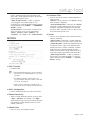
SCAN
OTHER FUNCTIONS
• Function
• Preset Lock
The Scan function allows running sequence of
Presets, Pattern and/or Auto Pans. Max 8 Scan
can be stored. Each Scan can have max 20 action
entities which can be preset, pattern or Auto Pan.
Preset speed can be set up and the repeat number
of Pattern & Auto Pan can be set up in Scan setup.
Dwell time between actions can be set up also.
Dwell Time
Preset 1
Pattern 1
Scan 1
Max 20 Entities
• Set Scan
Use OSD Menu to create a Scan.
• Run Scan
Method1) <Run Scan> [Scan NO]
ex) Run Scan 2 : <Run Scan> [2]
Method2) <Go Preset> [Scan NO.+150]
ex) Run Scan 7 : <Go Preset> [157]
• Delete Scan
Use OSD Menu to delete.
SCHEDULE
• Function
The Schedule function allows running an appropriate
function like Preset, Auto Pan, Scan, Pattern, Home
move at designated day and time. For example, if you
setup a rule Tuesday at 9:00AM and Preset 1 (say
Main Gate), the camera will move to main gate every
Tuesday at 9:00AM. If you choose Weekday, camera
will move to Main gate everyday except weekend.
It is noted that due to the real time clock, the time
data will be kept regardless of blackout. The initial
time and day setup is essential to proper Schedule
function.
• Set Schedule
Use OSD Menu to create a Schedule.
• Run Schedule
Use OSD Menu of Schedule Master Enable.
• Delete Schedule
This function is made to protect preset data from
unauthorized overwriting. If Preset Lock is ON, Preset
save command using Hot Key is disabled while Preset
save using OSD Menu is acceptable.
• Power Up Action
This function enables to resume the last action executed
before power down. Most of actions such as Preset,
Pattern, Auto Pan and Scan are available for this function
but Jog actions are not available to resume.
if there are no setup for those functions like
Preset, Pattern, Auto Pan and Scan, Camera will
automatically move to Home position after rebooting.If
Power Up Action is set to be ON, camera will continue
the function which is executed lastly after rebooting.
• D-Flip
In case that tilt angle arrives at the top of tilt orbit
(90°), zoom module camera keep moving to opposite
tilt direction (180°) to keep tracing targets. As soon
as zoom module camera passes through the top
of tilt direction (90°), images should be reversed
automatically and F appears in screen. If this function
is set to OFF, tilt movement range is 0 ~ 90°.
• Parking Action
This function enables to locate the camera to specific
position automatically if operator doesn’t operate the
controller for a while. The Park Time can be defined as
an interval from 5 seconds to 4 hours.
• Alarm Input
8 Alarm Inputs are used. If an external sensor is
activated, camera can be set to move to
corresponding preset position. It is noted that the
latest alarm input is effective if multiple sensors are
activated.
• Alarm Output
There are 4 Ch. of Alarm Outputs and all of them can
be assigned to a certain Preset number. For example,
if you assign Preset 5 to AO2, calling Preset 5 result in
turning On of AO2.
• Privacy Zone Mask
To protect privacy, Max. 8 Privacy Masks can be
created on the arbitrary position to hide objects such
as windows, shops or private house. With Spherical
Coordinates system, powerful Privacy Zone Mask
function is possible.
Use OSD Menu to delete.
English – 21
operation
• GENERAL/SPECIAL Image Setup
• Action Title
WB (White Balance) and AE (Auto Exposure) can
be set up independently for each preset. There are
2 modes, “General” mode & “Special” mode. The
General mode means that WB or AE can be set up
totally and simultaneously for all presets in “CAMERA
SETUP” menu. The Special mode means that WB
or AE can be set up independently or separately for
each preset in each preset setup menu. Each Special
WB/AE value should activate correspondingly when
camera arrives at each preset location.
During jog operation, General WB/AE value should be
applied. All Special WB/AE value will not be changed
although General WB/AE value change.
• ONEAF Focus
This mode exchanges focus mode automatically
between Manual Focus mode and Auto Focus mode
by operation. Manual Focus mode activates in preset
operation and Auto Focus mode activates during jog
operation. With Manual mode at presets, Focus data
is memorized in each preset in advance and camera
calls focus data in correspondence with presets as
soon as camera arrives at a preset. It should shorten
time to get focuses.
Followings are possible Action Titles and their meaning.
“SET PRESET ×××”
When Preset ××× is stored
“PRESET ×××”
When camera reach to
Preset ×××
“PATTERN ×”
When Pattern × is in action
“AUPx/PRESET XXX” When Auto Pan x is in action
“UNDEFINED”
When undefined function is
called to run
• Preset Label
The Label stored for specific Preset.
• Alarm Information
This information shows current state of Alarm Input.
The “I” means Input and “O” is output. If an Input is
ON state it will show the number of input. If an Input is
OFF state, ‘-’ will be displayed. In the same way
“O :1” means output 1 is ON “O :-” is OFF.
ex) When Point 2 of inputs are ON, and Output 1 is
On, OSD will show as below
Focus mode changes to Auto Focus mode
automatically when jog operation starts.
• Image Flip
OSD DISPLAY OF MAIN SCREEN
Shows that images are currently reversed by D-Flip
Function.
• Date/Time
Preset Lable 1
LABEL12345
PRESET1
Action Title
Displays Current Date and Time.
GENERAL RULES OF KEY
OPERATION FOR MENU
Date/Time
Camera ID
01/MAY/2009
00:00:01
CAM 1
Alarm Information
P/T/Z Information
Image Flip
Camera ID
• P/T/Z Information
Current Pan/Tilt angle in degree, zoom magnification
and a compass direction.
• Camera ID
Current Camera ID (Address).
22 – 36x Network Smart Dome Camera
• The menu items surrounded with < > always has its
sub menu.
• For all menu level, to go into sub menu, press ENTER
key.
• To go to up-one-level menu, select BACK button.
• To move from items to item in the menu, use joystick
in the Up/Down or Left/Right.
• To change a value of an item, use Up/Down of the
joystick in the controller.
• Press ENTER key to save values.
how to use osd menu
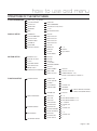
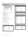
STRUCTURE OF THE SETUP MENU
SYSTEM INFORMATION
DISPLAY SETUP
SNC-C7478_v1.XX_XXXXXX
COLOR SYSTEM
PROTOCOL
BAUD RATE
ADDRESS
MAC
CAMERA ID
PTZ INFORMATION
ACTION TITLE
PRESET LABEL
ALARM I/O
DATE/TIME
<PRIVACY ZONE>
NTSC/PAL
AUTO/SAMSUNG
4800/9600/19200/38400
1~255
XX:XX:XX:XX:XX:XX
ON/OFF
AUTO/OFF/ON
AUTO/OFF/ON
AUTO/OFF/ON
AUTO/OFF/ON
ON/OFF
MASK NO.
DISPLAY
CLEAR
<EDIT MASK>
MOTION SETUP
PRESET LOCK
PWR UP ACTION
D-FLIP
JOG MAX SPEED
JOG DIRECTION
IMAGE HOLD
<PARKING ACTION SETUP>
FUNCTION SETUP
PRESET SETUP
AUTO PAN SETUP
OFF/ON
ON/OFF
ON/OFF
2~200/SEC
INVERSE/NORMAL
OFF/ON
PARK ENABLE
WAIT TIME
PARK ACTION
PRESET NO.
<EDIT SCENE>
<LABEL>
CLR PRESET
CAM ADJUST
CANCEL/OK
GENERAL
<SPECIAL>
<WHITE BALANCE SETUP>
<AUTO EXPOSURE SETUP>
APAN NO.
1~8
NOT USED/PRESET1~128
NOT USED/PRESET1~128
1~180/SEC
CANCEL/OK
1~4
CANCEL/OK
…
1~8
CANCEL/OK
…
APAN SPEED
CLEAR APAN
PATTERN NO.
CLEAR PATTERN
<EDIT PATTERN>
SCAN NO.
CLEAR SCAN
<EDIT SCAN>
SCHEDULE SETUP
1~128
…
…
OFF/ON
2ND POS.
SCAN SETUP
OFF/ON
00:00:05~04:00:00
HOME/PRESET1~128 /
SCAN1~8/PATTERN1~4/APAN1~8
ALARM OUT
1ST POS.
PATTERN SETUP
1~8
ON/OFF
OK/CANCEL
…
…
English – 23
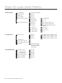
how to use osd menu
CAMERA SETUP
FOCUS MODE
DIGITAL ZOOM
IMAGE FLIP
FLICKERLESS
WHITE BALANCE SETUP
AUTO EXPOSURE SETUP
AUTO/ONEAF/MANUAL
ON/OFF
OFF/ON
OFF/ON
WB MODE
RED ADJUST
BLUE ADJUST
WDR/BLC
DAY/NIGHT
AE MODE
* IRIS LEVEL
* GAIN LEVEL
* SHUTTER SPD
* BRIGHTNESS
SYSTEM SETUP
<RELAY TYPE>
<PASSWORD>
<SET HOME POSITION>
<SET NORTH DIRECTION>
LANGUAGE
SYSTEM INITIALIZE
CLEAR ALL DATA
* CLR DISPLAY SET
* CLR CAMERA SET
* CLR MOTION SET
* CLR FUNCTION SET
REBOOT CAMERA
REBOOT SYSTEM
24 – 36x Network Smart Dome Camera
RELAY 1
RELAY 2
RELAY 3
RELAY 4
…
…
…
ENGLISH/ ESPAÑOL/
FRANÇAIS/ DEUTSCH/
ITALIANO/ РУССКИЙ/
PORTUGUÊS
NO/YES
NO/YES
NO/YES
NO/YES
NO/YES
NO/YES
NO/YES
AUTO/MANUAL
0 ~ 255
0 ~ 255
ALLOFF/WDR ON/BLC ON
AUTO1/AUTO2/DAY/NIGHT
AUTO/MANUAL/IRIS/SHUTTER/
BRIGHT
CLOSE~F1.6
-3~+28dB
1/60~1/10000
0~31
NORMAL OPEN / NORMAL CLOSE
NORMAL OPEN / NORMAL CLOSE
NORMAL OPEN / NORMAL CLOSE
NORMAL OPEN / NORMAL CLOSE
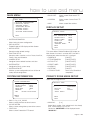
how to use osd menu
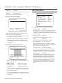
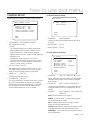
MAIN MENU
ROOT MENU
<SYSTEM INFORMATION>
<DISPLAY SETUP>
<MOTION SETUP>
<FUNCTION SETUP>
<CAMERA SETUP>
<SYSTEM SETUP>
<SYSTEM INITIALIZE>
EXIT
• SYSTEM INFORMATION
Shows info and current configuration.
• DISPLAY SETUP
Enable/Disable of OSD display on Main Screen.
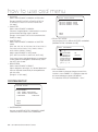
• BAUD RATE
Shows current Baud rate of PTZ
control.
• ADDRESS
Shows current Camera ID for PTZ
control.
• MAC
Shows current Mac address.
DISPLAY SETUP
DISPLAY SETUP
CAMERA ID
PTZ INFORMATION
ACTION TITLE
PRESET LABEL
ALARM I/O
DATE/TIME
<PRIVACY ZONE>
ON
AUTO
AUTO
AUTO
AUTO
ON
BACK
EXIT
• MOTION SETUP
Setup for motion related settings.
• FUNCTION SETUP
Setup for various functions such as Preset, Auto Pan,
Pattern, Scan and Schedule.
• CAMERA SETUP
Configure Camera related functions and data.
• SYSTEM SETUP
Configure for Basic system setup.
• SYSTEM INITIALIZE
Initializes system configuration and sets all data to
factory default configuration.
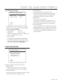
SYSTEM INFORMATION
This menu defines Enable/Disable of OSD display on
Main Screen. If an item is set to be AUTO, the item is
displayed only when the value of it is changed.
• CAMERA ID
[ON/OFF]
• PTZ INFORMATION
[ON/OFF/AUTO]
• ACTION TITLE
[ON/OFF/AUTO]
• PRESET LABEL
[ON/OFF/AUTO]
• ALARM I/O
[ON/OFF/AUTO]
• DATE/TIME
[ON/OFF]
• <PRIVACY ZONE>
Start Privacy Zone Mask
setup Menu.
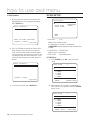
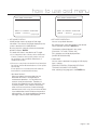
PRIVACY ZONE MASK SETUP
Select area in image to mask.
SYSTEM INFORMATION
SNC-C7478_v1.XX_XXXXXX
COLOR SYSTEM
NTSC
PROTOCOL
AUTO
BAUD RATE
9600
ADDRESS
1
MAC
00:0D:F1:30:00:00
BACK
EXIT
• SNC-C7478_v1.XX_XXXXXX
Shows current firmware version of camera.
• COLOR SYSTEM
Shows current analog video system of the camera
• PROTOCOL
Shows current Protocol for PTZ control
PRIVACY ZONE
MASK NO.
DISPLAY
CLEAR
<EDIT MASK>
1
UNDEFINED
OFF
CANCEL
BACK
EXIT
• MASK NO.
[1~8]
Select Mask number. If the selected mask has already
data, camera moves as it was set.
Otherwise, “UNDEFINED” will be displayed under
“MASK NO.”.
English – 25
how to use osd menu
• DISPLAY
[ON/OFF]
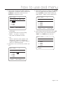
MOTION SETUP
Sets if camera makes mask shows or not on images.
• CLEAR
[CANCEL/OK]
MOTION SETUP
Deletes data in the selected mask NO.
PRESET LOCK
PWR UP ACTION
D-FLIP
JOG MAX SPEED
JOG DIRECTION
IMAGE HOLD
<PARKING ACTION
❖ Privacy Zone Area Setup
EDIT MASK 1
OFF
ON
ON
140/SEC
NORMAL
OFF
SETUP>
BACK
EXIT
Setup the general functions of Pan/Tilt motions.
MOVE TO TARGET POSITION
[ENTER : SELECT]
0/0/x1/N
Move camera to area to mask. Then the menu to
adjust mask size will be displayed.
If the tilt angle is located in the range between 70° to 90°,
you can not set up privacy zone mask.
If tilt angle over 90° (image flipped region) is designated,
camera will automatically move to identical poison by
changing tilt angle less than 90° and moving pan angle
180° relatively.
❖ Privacy Zone Size Adjustment
EDIT MASK 1
• PRESET LOCK
[ON/OFF]
If Preset Lock is set to ON, it is impossible to set up
and delete Preset. It is possible only to run those
functions. To set up and delete those functions, enter
into OSD menu.
• PWR UP ACTION
[ON/OFF]
Refer to “Other Functions”(page 21) section.
• D-FLIP
[ON/OFF]
Refer to “Other Functions”(page 21) section.
• JOG MAX SPEED
[2°/sec ~200°/sec]
Sets maximum jog speed. Jog speed is inversely
proportional to ratio of zoom. As zoom magnification
goes up, pan/tilt speed goes down.
• JOG DIRECTION
[INVERSE/NORMAL]
If you set this to ‘Normal’, the view in the screen is
moving same direction with jog tilting. If ‘Inverse’ is
selected, the view in the screen is moving reversely.
• IMAGE HOLD
[ZOOM : COLOR CHANGE]
[◄►:ADJUST MASK WIDTH]
[▲▼:ADJUST MASK HEIGHT]
[ENTER : SELECT]
Adjust mask size. Use joystick or arrow buttons to
adjust mask size.
• ◄► (Left/Right)
Adjusts mask width.
• ▲▼ (Up/Down)
Adjusts mask height.
• ZOOM In/Out
Change Color of mask.
To hide a certain zone completely regardless of high speed PT
motions, it is recommended that the size of mask must be 20%
bigger than original target size.
It is noted that during PAN/TILT control like jog action, the
object behind the privacy mask can be disclosed in a short
period of time.
26 – 36x Network Smart Dome Camera
[ON/OFF]
At start point of preset movement, camera starts
freezing the image of start point. Camera keeps
displaying the image of start point during preset
movement and does not display the images which
camera gets during preset movement. As soon as
camera stops at preset end point, camera starts
displaying live images which it gets at preset end
point.
how to use osd menu
❖ Parking Action Setup
• PATTERN SETUP
Up to 4 patterns can be stored in the dome.
PARKING ACTION SETUP
PARK ENABLE
WAIT TIME
PARK ACTION
OFF
00:10:00
HOME
In this function, path data created by manual move
of Joystick are recorded and you can playback the
identical path automatically whenever required.
• SCAN SETUP
Up to 8 Scans can be defined.
In a Scan, max 20 entities are assigned from any
combinations of Preset/Auto Pan/Pattern. If you run a
Scan, camera will execute each entry sequentially.
BACK
EXIT
• SCHEDULE SETUP
If Park Enable is set to ON, camera runs assigned
function automatically if there is no PTZ command
during assigned “WAIT TIME”.
• PARK ENABLE
[ON/OFF]
• WAIT TIME
[5 sec ~ 4 hour]
7 rules of Schedule can be assigned by day and time.
Appropriate actions (such as Home, Preset, Auto Pan,
Pattern and Scan) can be defined for each rule. Also,
it is possible to use Weekday and Weekend in a rule
to make it simple.
The time is displayed with “hh:mm:ss” format and
you can change this by 1 sec unit.
• PARK ACTION
[HOME/PRESET/PATTERN/AUTOPAN/SCAN]
ex) If HOME is selected for Park Action, camera
will move to home position when there is no PTZ
command during assigned “WAIT TIME”.
FUNCTION SETUP
FUNCTION SETUP
<PRESET SETUP>
<AUTO PAN SETUP>
<PATTERN SETUP>
<SCAN SETUP>
<SCHEDULE SETUP>
BACK
EXIT
Configure 5 Special Functions with this menu.
• PRESET SETUP
127 Presets from the number 1 to 128 can be
assigned excluding preset 95 reserved for Menu.
• AUTO PAN SETUP
Up to 8 Auto Pans are available, which makes camera
to move slowly between two preset points.
English – 27
how to use osd menu
❖ Edit Preset Scene
PRESET SETUP
EDIT SCENE - PRESET 1
PRESET SETUP
PRESET NO.
1
<EDIT SCENE>
<LABEL>
CLR PRESET
CAM ADJUST
ALARM OUT
CANCEL
GENERAL
----
MOVE TO TARGET POSITION
[ENTER : SELECT]
0/0/x1/N
BACK
EXIT
• PRESET NO.
[1~128]
If a selected preset is already defined, camera moves
to pre-defined position and preset characteristics such
as Label and Relay Outputs show on monitor. If a
selected preset is not defined, “UNDEFINED” shows
on monitor.
• EDIT PRESET SCENE
c Using joystick, move camera to desired position.
d By pressing ENTER key, save current PTZ data.
❖ Edit Preset Label
Redefine current Preset scene position (i.e. PTZ).
LABEL - PRESET 1
• EDIT PRESET LABEL
[█
]
---------1234567890
ABCDEFGHIJ
KLMNOPQRST
UVWXYZabcd
efghijklmn
opqrstuvwx
yz<>-/:.
Edits Label to show on monitor when preset runs.
Max. 10 alphabets are allowed.
• CLR PRESET
[CANCEL/OK]
Delete current Preset data
• CAM ADJUST
[GENERAL/SPECIAL]
WB(White Balance) and AE(Auto Exposure) can be set
up independently for each preset. There are 2 modes,
“GENERAL” mode & “SPECIAL” mode. The General
mode means that WB or AE can be set up totally and
simultaneously for all presets in “CAMERA SETUP”
menu.
The Special mode means that WB or AE can be set
up independently or separately for each preset in each
preset setup menu. Each Special WB/AE value should
activate correspondingly when camera arrives at each
preset location. During jog operation, General WB/AE
value should be applied.
All Special WB/AE value should not change although
General WB/AE value changes. If “SPECIAL” is
selected, Menu to set WB/AE shows on monitor.
• ALARM OUT
State of four alarm outputs can be freely controlled in
conjunction with Preset run. The character “-” means
OFF state and the number representing each bit
means ON.
ex) If it is set to be -23-, Output relay 2, 3 will be ON
and 1, 4 will be OFF, when you run this Preset.
28 – 36x Network Smart Dome Camera
OK
CANCEL
c Edits label to show on monitor when camera
arrives at presets. In Edit Label menu, a reverse
rectangular is cursor. As soon as finishing selecting
alphabet, cursor moves to the next digit.
[
]
Current Cursor Position
d Using Left/Right/Up/Down of joystick, move to
an appropriate character from the Character set.
To choose that character, press the ENTER key.
how to use osd menu
Back Space Char.
Space Char.
When Auto Pan function runs, camera moves from
the preset assigned as the 1st point to the preset
assigned as the 2nd point in CW(Clockwise) direction.
Then camera moves from the preset assigned as the
2nd point to the preset assigned as the 1st point in
CCW(Counterclockwise) direction. In case that the
preset assigned as the 1st point is same as the preset
assigned as the 2nd point, camera turns on its axis by
360° in CW direction and then it turns on its axis by
360° in CCW direction.
• APAN SPEED
If you want to use blank, choose Space character
(“ ”). If you want to delete a character before, use
back space character (“ ”).
e If you complete the Label editing, move cursor to
“OK” and press ENTER key to save completed
label. To abort current change, move cursor to
“CANCEL” and press ENTER key.
AUTO PAN SETUP
[1°/sec ~180°/sec]
Sets Auto Pan speed from 1°/sec to 180°/sec.
• CLEAR APAN
[CANCEL/OK]
Deletes current Auto Pan data.
PATTERN SETUP
PATTERN SETUP
PATTERN NO.
AUTO PAN SETUP
APAN NO.
1ST POS.
2ND POS.
1
NOT USED
NOT USED
APAN SPEED
CLEAR APAN
30/SEC
CANCEL
1
UNDEFINED
CLEAR PATTERN CANCEL
<EDIT PATTERN>
BACK
EXIT
BACK
EXIT
• PATTERN NO.
[1~4 ]
Selects Pattern number to edit.
• APAN NO.
[1~8]
Selects Auto Pan number to edit. If a selected Auto
Pan has not defined, “NOT USED” is displayed in 1st
Position and 2nd Position
• 1ST POS. / 2ND POS.
[PRESET 1~128]
Set up the 2 position for Auto Pan function. If a
selected preset is not defined, “UNDEFINED” will be
displayed as shown below.
If a selected pattern number is not defined,
“UNDEFINED” will be displayed under selected
pattern number.
• CLEAR PATTERN
[CANCEL/OK]
Deletes data in current pattern
• EDIT PATTERN
Starts editing pattern.
AUTO PAN SETUP
APAN NO.
1ST POS.
2ND POS.
1
PRESET5
NOT USED
UNDEFINED
English – 29
how to use osd menu
❖ Edit Pattern
SCAN SETUP
c By using Joystick, move to start position with
appropriate zoom. To start pattern recording,
press ENTER key.
SCAN SETUP
SCAN NO.
1
UNDEFINED
CANCEL
CLEAR SCAN
<EDIT SCAN>
EDIT PATTERN 1
BACK
EXIT
MOVE TO START POSITION
[ENTER : START]
0/0/x1/N
d Use Pan/Tilt/Zoom to specify the Pattern Start
point and press Enter. If you run a pattern to
save, the route of the pattern will be recorded.
The total memory size and the rest memory size
is displayed in the form of bar. Maximum 1,000
communication commands can be stored in a
pattern.
EDIT PATTERN 1
• SCAN NO.
[1~8]
Selects Scan number to edit.
If a selected Scan number is not defined,
“UNDEFINED” will be displayed under selected Scan
number.
• CLEAR SCAN
[CANCEL/OK]
Deletes data in current Scan
• EDIT SCAN
Starts editing Scan.
❖ Edit Scan
c Press ENTER key in “NO” list to start Scan
setup.
EDIT SCAN
1
NO. ACTION NO. DWELL OPT
1
2
3
4
5
[ENTER : SAVE]
0/0/X1/N
e To save data and exit, press ENTER key.
NONE
NONE
NONE
NONE
NONE
SAVE
CANCEL
[ENTER : EDIT]
d Note that Max. 20 Functions are allowed in a
Scan. Move cursor up/down and press ENTER
key to set up.
EDIT SCAN
1
NO. ACTION NO. DWELL OPT
1
2
3
4
5
NONE
NONE
NONE
NONE
NONE
SAVE
[ENTER : EDIT ACT]
CANCEL [LEFT : EDIT END]
30 – 36x Network Smart Dome Camera
how to use osd menu
e Set up Action, Dwell time and Option. Note that
selected item is displayed in reverse. Move cursor
Left/Right to select items and move cursor
Up/Down to change each value.
EDIT SCAN
1
NO. ACTION NO. DWELL OPT
1
2
3
4
5
NONE
NONE
NONE
NONE
NONE
SAVE
CANCEL
EDIT SCAN
[◄ ►:MOVE CURSOR]
[▲▼:CHANGE VAL.]
[NONE/PRESET/AUTO PAN/PATTERN]
[1 second ~ 4 minutes]
1
NO. ACTION NO. DWELL OPT
1
2
3
4
5
• ACTION NO.
• DWELL
g After finishing setting up an Action, press ENTER
key to one-upper-level menu (Step d). Move
cursor Up/Down to select Action number and
repeat Step d ~ Step f to edit selected Scan.
PRESET
NONE
NONE
NONE
NONE
1 00:03 360
SAVE
[ENTER : EDIT ACT]
CANCEL [LEFT : EDIT END]
h After finishing setting up all Actions, press LEFT
key to exit. Then cursor should be moved to
“SAVE”. Press ENTER key to save data.
Sets Dwell Time between functions
EDIT SCAN
• OPT
Option. It represents preset speed (2~360)
when preset is selected. It should be the
number of repetition (1~255) when Pattern or
Auto Pan is selected for Action
f Set up items such as ACTION NO., DWELL and
OPT.
EDIT SCAN
1
1
NO. ACTION NO. DWELL OPT
1
2
3
4
5
PRESET
NONE
NONE
NONE
NONE
1 00:03 360
SAVE
CANCEL
NO. ACTION NO. DWELL OPT
1
2
3
4
5
PRESET
NONE
NONE
NONE
NONE
SAVE
CANCEL
1 00:03 360
[◄ ►:MOVE CURSOR]
[▲▼:CHANGE VAL.]
English – 31
how to use osd menu
The meaning of each value:
SCHEDULE SETUP
DAY
Days: MON TUE
FRI SAT SUN
SCHEDULE SETUP
MASTER ENABLE
DAY TIME ACT
1 UNDEFINED
2 UNDEFINED
3 UNDEFINED
4 UNDEFINED
5 UNDEFINED
6 UNDEFINED
7 UNDEFINED
BACK
NO
24hour Format
ACT
PRS(Preset), AUP(Auto Pan),
PTN(Pattern), SCN(Scan),
HOM(Home)
If you finish a rule, press ENTER key to select
another rule.
Decide whether Schedule function is active or not.
Start editing Schedule.
❖ Edit Schedule
c After move the Cursor to the number by using
Up/Down keys, press ENTER Key to edit.
SCHEDULE SETUP
NO
Repeat this procedure to fill up the schedule in
mind.
e Example
Delete all data in current Menu
ON
ON
– The second rule means camera will move
to Preset 12 position at 7:35 on every
Wednesday.
SCHEDULE SETUP
MASTER ENABLE
DAY TIME ACT
1 MON 01:20 HOM
2 WED 07:35 PRS
3 THU 11:40 SCN
4 SAT 15:17 PTN
5 WKD 23:00 HOM
6 UNDEFINED
7 UNDEFINED
BACK
NO
12
3
1
ON
ON
ON
ON
ON
ON
ON
* Note: If there are rules conflicts to each other, the
higher number is, the higher priority has.
d Each field can be selected by Left/Right keys
and the values in the field are changed using
Up/Down keys.
SCHEDULE SETUP
MASTER ENABLE
DAY TIME ACT
1 MON 00:00 HOM
2 UNDEFINED
3 UNDEFINED
4 UNDEFINED
5 UNDEFINED
6 UNDEFINED
7 UNDEFINED
BACK
ALL: All days(Everyday)
TIME
ON/OFF Decide to make this rule effective or
not
• CLEAR SCHEDULE [CANCEL/OK]
MASTER ENABLE
DAY TIME ACT
1 UNDEFINED
2 UNDEFINED
3 UNDEFINED
4 UNDEFINED
5 UNDEFINED
6 UNDEFINED
7 UNDEFINED
BACK
THU
WKD: Weekday
ON
ON
• MASTER ENABLE [ON/OFF]
• EDIT SCHEDULE
WED
NO
32 – 36x Network Smart Dome Camera
ON
ON
OFF
* Note: If you assign undefined function, there will be
no action.
* Hint: Using reserved Preset, you can make various
schedules. For example, PRS179 are PRS178 are
Day and Night mode respectively.
(Refer to Reserved Preset(page 19) List in this
manual.)
how to use osd menu
CAMERA SETUP
Setup the general functions of zoom camera module
ZOOM CAMERA SETUP
FOCUS MODE
ONEAF
DIGITAL ZOOM ON
IMAGE FLIP
OFF
FLICKERLESS
OFF
<WHITE BALANCE SETUP>
<AUTO EXPOSURE SETUP>
BACK
EXIT
❖ White Balance Setup
WB SETUP
WB MODE
- RED ADJUST
- BLUE ADJUST
BACK
EXIT
• WB MODE
• FOCUS MODE [AUTO/MANUAL/ONEAF]
[AUTO/MANUAL]
In Manual mode, Red and Blue level can be set up
manually
Sets camera focus mode.
• RED ADJUST
ONEAF
• BLUE ADJUST [0~255]
This mode exchanges focus mode automatically
between Manual Focus mode and Auto Focus
mode. Manual Focus mode activates in preset
operation and Auto Focus mode activates when jog
operation starts.
With Manual mode at presets, Focus data is
memorized in each preset in advance and camera
calls focus data in correspondence with presets as
soon as camera arrives at a preset.
• DIGITAL ZOOM [ON/OFF]
Sets digital zoom function to ON/OFF. If this is set to
OFF, optical zoom function runs but zoom function
stops at the end of optical zoom magnification.
• IMAGE FLIP
[0~255]
❖ Auto Exposure Setup
AE SETUP
WDR/BLC
DAY/NIGHT
AE MODE
IRIS LEVEL
GAIN LEVEL
SHUTTER SPD
BRIGHTNESS
ALL OFF
AUTO 1
AUTO
----AUTOX16
---
BACK
EXIT
[ON/OFF]
To display Upside down image.
• FLICKERLESS
AUTO
-----
[ON/OFF]
This is for preventing a flickering screen that is caused
by a mismatch between the vertical sync frequency
and the flicker frequency of the lighting; if set to ON,
the AE mode will switch to Shutter mode and the
shutter speed will be fixed at 1/100 second.
• WDR/BLC
[ ALL OFF / WDR ON / BLC ON ]
Select WDR(Wide Dynamic Range) or BLC(Backlight
Compensation) function. All OFF means turning off
both functions.
• DAY/NIGHT
[AUTO 1/AUTO 2/DAY/NIGHT]
The illumination condition for switching between Day
and Night modes of AUTO1 is brighter than that of
AUTO2.
• AE MODE
[AUTO / MANUAL / IRIS / SHUTTER
/ BRIGHT]
AUTO: Full Auto mode for AE function
MANUAL: In manual mode. Iris, Gain, Shutter Speed
can be changed in this mode.
IRIS: Iris priority mode. You can change Iris while
others are adjusted automatically.
SHUTTER: Shutter priority mode. Shutter speed can be
changed while others are adjusted automatically.
BRIGHTNESS: In this mode, you can assign AE value in
terms of Brightness.
English – 33
how to use osd menu
• IRIS LEVEL
Works when AE MODE is MANUAL or IRIS model
[Range: CLOSE/F1.6/F2/F2.4/F2.8/F3.4/F4/F4.8/
F5.6/F6.8/F8/ F9.6/F11/F14/F16/F19/F22/F28.
(18 steps)]
RELAY TYPE SETUP
RELAY1
RELAY2
RELAY3
RELAY4
NORMAL
NORMAL
NORMAL
NORMAL
OPEN
OPEN
OPEN
CLOSE
• GAIN LEVEL
Works when AE MODE is MANUAL
Enhances image brightness automatically in case that
luminance level of image signal is too low.
[Range: -3/0/2/4/6/8/10/12/14/16/18/20/22/24/26/
28dB (16 steps)]
• SHUTTER SPD
Works when AE MODE is MANUAL or SHUTTER
mode
[X64, X32, X16, X8, X4, X2,1/60,1/90,1/100,1/125,1/
180,1/250,1/350,1/500,1/725,1/1000,1/1500,1/
2000,1/4000,1/6000,1/10000]
Works when AE MODE is AUTO mode
[OFF, AUTO X2, AUTO X4, AUTO X8, AUTO X16]
If you want to sense the light brightness to control the
shutter speed to the brightness automatically, select
the AUTO slow shutter.
BACK
EXIT
• RELAY TYPE SETUP
Contact types of 4 Ch. RELAY OUTPUTS are defined.
[NORMAL OPEN / NORMAL CLOSE]
EDIT PASSWORD
[█
]
---------1234567890
ABCDEFGHIJ
KLMNOPQRST
UVWXYZabcd
efghijklmn
opqrstuvwx
yz<>-/:.
OK
CANCEL
DISABLE
• BRIGHTNESS
Works when AE MODE is BRIGHT
Adjusts brightness of images. Iris, Shutter Speed and
Gain are adjusted automatically in correspondence
with this value.
[Range: 0~31 (32 steps)]
• EDIT PASSWORD
You can define 4 characters long password. If this
function is set to ENABLE, it is required to type this
password whenever to enter OSD MENU.
It is noted that DEFAULT PASSWORD : “4321”
SYSTEM SETUP
SYSTEM SETUP
<RELAY TYPE>
<PASSWORD>
<SET HOME POSITION>
<SET NORTH DIRECTION>
LANGUAGE
ENGLISH
BACK
EXIT
• SYSTEM SETUP
You can set up RELAY TYPE, PASSWORD, HOME
POSITION, NORTH DIRECTION, LANGUAGE.
34 – 36x Network Smart Dome Camera
how to use osd menu
SET HOME POSITION
SET NORTH DIRECTION
MOVE TO TARGET POSITION
[ENTER : SELECT]
0/0/x1/N
MOVE TO TARGET POSITION
[ENTER : SELECT]
0/0/x1/N
• SET HOME POSITION
• SET NORTH DIRECTION
HOME position means the origin of PAN angle
calculation. The value of PAN angle displayed on the
screen is based on this HOME position.
You can set up North direction.
By using Joystick, move the camera to the desired
position and press ENTER.
The direction will be displayed in the screen
It is noted that Home is not effective to Tilt angle.
If you change the location of Home position, all horizontal
locations of functions such as preset, pattern, scan, auto
pan, and privacy zone mask will be shifted based on
changed Home position.
If there are no setup for those functions like Preset, Pattern, Auto
Pan and Scan, Camera will automatically move to Home position
after rebooting.
If Power Up Action is set to be ON, camera will continue the
function which is executed lastly after rebooting.
By using Joystick, move the camera to the desired
NORTH position and press ENTER key.
[PAN AXIS / TILT AXIS / ZOOM / DD]
DD is direction and will be displayed from:
[N/NE/E/SE/S/SW/W/NW]
• LANGUAGE
You can select a preferred Language of OSD display
from 7 choices.
[ENGLISH/ ESPAÑOL/ FRANÇAIS/ DEUTSCH/
ITALIANO/ РУССКИЙ/ PORTUGUÊS]
After selecting a language, press the ENTER key.
* Set Home Position?
When you replace the camera block or the
orientation of camera is changed due to
maintenance operations, it is very difficult to
maintain same pan orientation. Therefore, all
function data depending on pan orientation such
as preset, pattern, scan, auto pan, and privacy
zone mask are not useful any more accordingly.
However, even in this case, you can reuse the data
if you redefine Set Home Position on the previous
Home position. It is recommendable to memorize
the target scene of current Home position.
English – 35
how to use osd menu
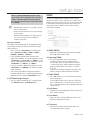
SYSTEM INITIALIZE
• Motion Configuration
SYSTEM INITIALIZE
Preset Lock
CLEAR ALL DATA
CLR DISPLAY SET
CLR CAMERA SET
CLR MOTION SET
CLR FUNCTION SET
REBOOT CAMERA
REBOOT SYSTEM
NO
NO
NO
NO
NO
NO
NO
BACK
EXIT
• CLEAR ALL DATA
Deletes all configuration data such as display, camera,
motion setup and so on.
• CLR DISPLAY SET
OFF
Power Up Action
ON
D-Flip
ON
Jog Max Speed
140°/sec
Jog Direction
NORMAL
Image Hold
OFF
Park Action
OFF
• Communication Setup
Protocol
AUTO
Baud Rate
9600
Initializes Display Configuration
• Camera Configuration
• CLR CAMERA SET
Initializes Camera Configuration
• CLR MOTION SET
Initializes Motion Configuration
• CLR FUNCTION SET
Deletes Preset Data, Auto Pan Data, Pattern Data,
Scan Data and Schedule Data
• REBOOT CAMERA
Reboots Zoom Camera module
• REBOOT SYSTEM
Reboots Smart Dome Camera
❖ Initial Configuration Table
Focus Mode
ONEAF
Digital Zoom
ON
Image Flip
OFF
Flickerless
OFF
White Balance
AUTO
Backlight/BLC
ALL OFF
Day/Night
AUTO 1
AE Mode
AUTO
Iris Level
F4
Gain Level
+2dB
Shutter Speed
1/60(MANUAL), AUTO X16(AUTO)
Brightness
13
• Function Data
• Display Configuration
Camera ID
ON
Preset 1~128
PTZ Information
AUTO
Auto Pan 1~8
Undefined
Action Title
AUTO
Pattern 1~4
Undefined
Preset Label
AUTO
Scan 1~8
Undefined
Alarm I/O
AUTO
Schedule 1~7
Undefined
Date/Time
ON
Privacy Zone
Undefined
36 – 36x Network Smart Dome Camera
Undefined
network connection & setup
You can set up the network settings according to your network configurations.
❖ Network connection and setup processes are given as follows.
• Connect the camera to an IP router with a xDSL/Cable modem. (Page 37~38)
• Connect the camera to an IP router with local area networking. (Page 39~40)
• Connect the camera directly to a DHCP-based xDSL/Cable modem. (Page 41)
• Connect the camera directly to local area networking. (Page 42)
M
Compliant IP routers are as listed below.
- Linksys
- D-Link
- Netgear
Using non-recommended IP router may cause the network connection error.
Depending on the performance of the PC (Viewer installed) or the network, the video transmission can be delayed or even
disconnected.
For soft video transmission, you can set the bandwidth in <NETWORK> → <STREAMING SETUP> in the setup menu.
J
The IP and MAC addresses used in this manual are for illustrative purposes only.
Therefore, you must refer to Notice the network settings of your PC and do not enter the addresses presented in this manual.
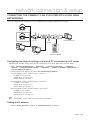
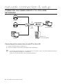
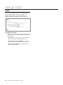
CONNECTING THE CAMERA TO AN IP ROUTER WITH THE XDSL/
CABLE MODEM
SNC-C7478
xDSL or Cable Modem
IP Router
xDSL or Cable Modem
External Remote PC
SNC-C7478
Local PC
DDNS Server
(Data Center, KOREA)
Configuring the network settings of the local PC connected to an IP router
Configuring the network settings of the local PC connected to an IP router, follow the instructions below.
• Select : <Network Neighborhood> → <Properties> → <Local Area Connection> → <Properties> →
<General> → <Internet Protocol (TCP/IP)> → <Properties> → <Obtain an IP address automatically> or
<Use the following IP address>
• Follow the instructions below if you select <Use the following IP address>:
ex1) If the address (LAN IP) of the IP router is 192.168.1.1
IP address: 192.168.1.100
Subnet Mask: 255.255.255.0
Default Gateway: 192.168.1.1
English – 37
network connection & setup
ex2) If the address (LAN IP) of the IP router is 192.168.0.1
IP address: 192.168.0.100
Subnet Mask: 255.255.255.0
Default Gateway: 192.168.0.1
ex3) If the address (LAN IP) of the IP router is 192.168.xxx.1
IP address: 192.168.xxx.100
Subnet Mask: 255.255.255.0
Default Gateway: 192.168.xxx.1
M
For the address of the IP router, refer to the product’s documentation.
Checking if the IP router is connected to the xDSL/Cable modem properly
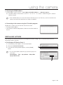
Select <Status> from the Settings menu of the IP Router.
• If it is properly connected, <IP Address>, <Subnet Mask> and <Gateway> provided by your ISP are displayed.
Please remember these values because they are required so that an external remote computer of the IP router
connects to the camera. However, note that certain ISPs change the settings of <IP Address>, <Subnet Mask>
and <Gateway> on a regular basis
• If the IP router is not properly connected, press the [Connect] button to try to reconnect or check if the settings of
the IP router are correct.
Setting the IP address
• Refer to "Setting Static IP" on page 44 or "Setting Dynamic IP" on page 47.
Connecting a local PC in the IP router to the camera
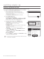
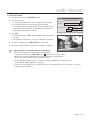
1. Run the IP Installer on your local PC and search for the camera.
2. If found, double-click the camera to start the Internet browser and
try to connect to the camera. Alternately, launch the Internet browser
manually and enter the IP address of the camera found in the address
bar to connect to it.
ex) http://192.168.1.2
Connecting to the camera from a remote PC
1. You can’t use the IP Installer on a remote PC that is not connected to the IP router.
This is because the IP Installer does not work on the Internet.
2. You can use DDNS URL of the camera to connect to the IP router internal camera.
3. However, you must set the port-forwarding for the IP router before you can connect to the IP router internal
camera from a remote PC.
For more information on the port-forwarding, refer to “Port Forwarding (Port Mapping) Setting” on page 47.
4. When the port forwarding is done, run the Internet browser on the remote PC and enter the DDNS URL address
or, the Internet IP address of the IP router in the address bar for connecting to the camera.
ex) http://e30002c.websamsung.net
• For the DDNS URL address, refer to “Checking the DDNS address” on page 49.
38 – 36x Network Smart Dome Camera
network connection & setup
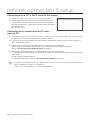
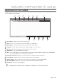
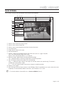
CONNECTING THE CAMERA TO AN IP ROUTER WITH LOCAL AREA
NETWORKING
This is for a large network environment such as corporate office, building, public office and factory.
SNC-C7478
SNC-C7478
IP Router
External Remote PC
Firewall
Local PC
Local PC
DDNS Server
(Data Center, KOREA)
Configuring the network settings of the local PC connected to an IP router
Configuring the network settings of the local PC connected to an IP router, follow the instructions below.
• Select : <Network Neighborhood> → <Properties> → <Local Area Connection> → <Properties> →
<General> → <Internet Protocol (TCP/IP)> → <Properties> → <Obtain an IP address automatically> or
<Use the following IP address>
• Follow the instructions below if you select <Use the following IP address>:
ex1) If the address (LAN IP) of the IP router is 192.168.1.1
IP address: 192.168.1.100
Subnet Mask: 255.255.255.0
Default Gateway: 192.168.1.1
ex2) If the address (LAN IP) of the IP router is 192.168.0.1
IP address: 192.168.0.1
Subnet Mask: 255.255.255.0
Default Gateway: 192.168.0.1
ex3) If the address (LAN IP) of the IP router is 192.168.xxx.1
IP address: 192.168.xxx.1
Subnet Mask: 255.255.255.0
Default Gateway: 192.168.xxx.1
M
For the address of the IP router, refer to the product’s documentation.
Setting the IP address
• Refer to "Setting Static IP" on page 44 or "Setting Dynamic IP" on page 47.
English – 39
network connection & setup
Connecting a local PC in the IP router to the camera
1. Run the IP Installer on your local PC and search for the camera.
2. If found, double-click the camera to start the Internet browser and
try to connect to the camera. Alternately, launch the Internet browser
manually and enter the IP address of the camera found in the address
bar to connect to it.
ex) http://192.168.1.2
Connecting to the camera from an IP router
external PC
1. An IP router external PC can’t use the IP Installer to search for an IP router internal camera. This is because the IP
Installer does not work in a network where the gateway is different.
2. In this case, you can use the DDNS URL of the camera or the Internet IP address of the IP router to connect to
the IP router internal camera.
3. However, you must set the port-forwarding for the IP router before you can connect
to the IP router internal camera from a remote PC. For more information on the port-forwarding,
refer to “Port Forwarding (Port Mapping) Setting” on page 47.
4. When the port forwarding is done, run the Internet browser on the IP router External
PC and enter the DDNS URL address or, the Internet IP address of the IP router in the address bar for connecting
to the camera.
ex) http://e30002c.websamsung.net
• For the DDNS URL address, refer to “Checking the DDNS address” on page 49.
M
A remote PC in an external Internet out of the LAN network may not be able to connect to the camera installed in the intranet if
the port-forwarding is not properly set or a firewall is set.
In this case, to resolve the problem, contact your network administrator.
40 – 36x Network Smart Dome Camera
network connection & setup
CONNECTING THE CAMERA DIRECTLY TO A DHCP-BASED XDSL/
CABLE MODEM
This is enabled for a modem using DHCP.
Setting the IP Router
1. Set the IP address referring to "Setting Static IP" on page 44 or "Setting Dynamic IP" on page 47.
2. Launch an Internet browser on the local PC connected to the IP Router.
3. Enter the IP Router’s address in the address bar of the browser.
ex) http://192.168.1.1 ,http://192.168.0.1 or http://192.168.xxx.1
• For the DDNS URL address, refer to “Checking the DDNS address” on page 49.
4. When the IP Router is connected, the login window appears and prompts you to enter the password.
M
For the login IP and the password, refer to the IP router’s documentation.
5. When done, you will see the setup window of the IP router. In the setup menu, select <Automatic
Configuration-DHCP> for <Internet Connection Type>.
M
For the menu location of <Internet Connection Type> or DHCP selection, refer to the IP router’s documentation.
6. When done, click the [Save] or [Apply] button to save the settings.
xDSL or Cable Modem
External Remote PC
SNC-C7478
DDNS Server
(Data Center, KOREA)
Connecting to the camera from a remote PC
1. Launch an Internet browser on the remote PC.
2. Enter the DDNS URL address in the address bar of the browser for connecting to the camera.
ex) http://e30002c.websamsung.net
• For the DDNS URL address, refer to “Checking the DDNS address” on page 49.
M
To check if your xDSL / Cable modem uses DHCP, contact your Internet Service Provider.
English – 41
network connection & setup
CONNECTING THE CAMERA DIRECTLY TO LOCAL AREA
NETWORKING
SNC-C7478
SNC-C7478
External Remote PC
Firewall
Local PC
DDNS Server
(Data Center, KOREA)
Connecting to the camera from a local PC in the LAN
1. Launch an Internet browser on the local PC.
2. Enter the IP address of the camera in the address bar of the browser.
M
A remote PC in an external Internet out of the LAN network may not be able to connect to the camera installed in the intranet if
the port-forwarding is not properly set or a firewall is set.
In this case, to resolve the problem, contact your network administrator.
42 – 36x Network Smart Dome Camera
network connection & setup
SEARCHING FOR THE CAMERA
❖ IP Installer screen layout
1
2
3
4
5
8
6
9
7
10
11
12
1 Device Name : Model name of the connected device.
2 Mode : Shows the current selection between <Static>and <Dynamic>.
3 MAC Address : The Mac address of the network interface of the camera.
4 IP Address : The IP address of the camera. (Default setting is '192.168.1.200'.)
5 Protocol : Indicates if the camera network environment is IPv4 or IPv6.
6 UPnP Status : This is unavailable for this camera.
7 URL : This is DDNS address that can be used to connect from an external Internet. However, if the DDNS update
fails, it will be displayed as an IP address of the camera.
8 IPv4, IPv6 Check Box : Searches for cameras only in the selected network environment.
9 Search Button : Searches for the camera connected to the current network.
10 Auto Set Button : Sets up the camera network settings automatically using the <IP Installer>.
11 Manual Set Button : Allows the user to set up the camera network settings manually.
12 Exit Button : Exits the IP Installer program.
M
On Windows Vista, the settings should be configured by the Administrator to use the IP installer normally.
English – 43
setting static ip
MANUAL NETWORK SETTING
Run the <IP Installer.exe> program and display the camera list found on the screen.
For the initial run, the [Auto Set] and [Manual Set] button are all disabled.
1. Select a camera you want from the camera list.
• Check the MAC address marked in the network box.
• Check the MAC address in System Information under the
Setup menu of the camera.
• The [Auto Set] and [Manual Set] button are activated.
1
2. Click the [Manual Set] button.
• The Manual Set window appears.
• The <IP Address>, <Subnet Mask>, <Gateway> and <HTTP
Port> values of the camera are displayed in their default values.
• The password is set to “4321” by factory default.
3. Set up the IP related settings in the <ADDRESS> field.
• <MAC Address>: The MAC Address is automatically
displayed. No additional setting is required.
2
3
If using an IP router :
• <IP Address>: Set it according to the private IP address range
provided by the IP Router.
ex) 192.168.1.2~254, 192.168.0.2~254, or 192.168.
XXX.2~254
• <Subnet Mask>: The IP Router’s <Subnet Mask> becomes
camera’s <Subnet Mask> value.
• <Gateway>: The IP Router’s <Local IP Address> becomes
camera’s <Gateway> value.
If not using an IP router :
• For the <IP Address>, <Gateway> and <Subnet Mask> settings,
contact your network administrator.
M
For the menu location of Internet Connection Type or DHCP selection, refer
to the IP router’s documentation.
44 – 36x Network Smart Dome Camera
3
setting static ip
4
4. In the <PORT>fields, set up port numbers.
• <HTTP Port>: A HTTP port used to connect to a camera using the
Internet browser. The default value is 80. The HTTP
port value can be changed by using the up/down
button to the right.
The HTTP port number starts with 80 and
increases/decreases to 10000, 10006, 10012…
• <Device Port>: A port used to control video transmission. The
5
6
default value is 60001(TCP).
• <TCP Port>: A port used to transfer video using TCP protocol.
The default value is 60002(TCP).
• <UDP Port>: A port used to transfer video using UDP protocol. The default value is 60003(UDP).
• <Upload Port>: A port used to upgrade software. The default value is 60004(TCP).
• <Multicast Port>: Shows UDP port set for video transmission using UDP Multicast. The default value is
60005(UDP).
5. Enter your password.
• The default password is “4321”.
• The password is the camera login password of the root user.
6. Click the [OK] button.
• The manual network setting is finished.
7. The camera is set to the manually entered IP and is restarted.
❖ If more than one camera are connected to an IP Router
Set the IP and port settings for camera differently.
Items
IP Related
Items
Port Related Items
M
1st Camera
2nd Camera
IP Address
192.168.1.200
192.168.1.201
Subnet Mask
255.255.255.0
255.255.255.0
Gateway
192.168.1.1
192.168.1.1
HTTP Port
80
10000
Device Port
60001
10001
TCP Port
60002
10002
UDP Port
60003
10003
Upload Port
60004
10004
Multicast Port
60005
10005
If <HTTP Port> is not set to 80,the user must specify the port number as well as the IP address in the Address input box of
an Internet browser to connect to the camera.
ex) http://IP Address: HTTP Port
e.g.) http://192.168.1.201: 10000
English – 45
setting static ip
AUTOMATIC NETWORK SETTING
Run the <IP Installer.exe> program and display the camera list found on the screen.
For the initial run, the [Auto Set] and [Manual Set] button are all disabled.
1. Select a camera you want from the camera list.
• The [Auto Set] and [Manual Set] button are activated.
1
2. Click the [Auto Set] button.
• The Auto Set window appears.
• The automatically found <IP Address>, <Subnet Mask> and
<Gateway> are displayed.
2
3. Enter your password.
• The password is the camera login password of the root user.
• The default password is “4321”.
4. Click the [OK] button.
• The automatic network setting is finished.
5. The camera automatically restarts when the network setting is
complete.
M
For the menu location of Internet Connection Type or DHCP selection, refer
to the IP router’s documentation.
4
46 – 36x Network Smart Dome Camera
3
setting dynamic ip
DYNAMIC IP SETTING
❖ Examples of using Dynamic IP
• If the camera is installed on an IP router and obtains an IP using
DHCP.
1
• If the camera is connected directly to a xDSL/Cable modem using
DHCP.
• If an IP is allocated by the internal DHCP server in local area
networking.
2
❖ Dynamic IP Check
1. When you run the IP Installer on your local PC, the camera with a
dynamic IP allocated is listed.
2. Select the camera in the list and click the [Manual Set] button to check
the camera for the current dynamic IP.
• In this case, the ADDRESS field is automatically filled and you can’t
change it. However, you can still change the port settings.
PORT FORWARDING (PORT MAPPING) SETTING
With the camera installed on an IP router, you must set the port forwarding for the IP router before an IP router external
remote PC can connect to the IP router internal camera.
❖ Manual Port Forwarding
1
1. Click <Applications &Gaming> → <Port Range Forward> from
the Settings menu of the IP Router.
• For the menu location and the setting of Port Forwarding, refer
to the IP router’s documentation.
2. Select the <TCP> and <UDP Port> for each camera connected
to the IP Router.
• Each of the port numbers for the IP Router must be according
to those presented in <BASIC> → <IP> of the SETUP screen of
the camera.
3. If the setting is complete, click the [Save Settings] button.
• The changes are saved.
2
3
English – 47
using the camera
CONNECTING TO THE CAMERA
❖ Connecting to the camera
General
• Run an Internet browser.
• Enter the IP address for the camera in the Address input box.
ex) IP Address: 192.168.1.200 → http://192.168.1.200
- The login window appears.
If the HTTP port number is not 80
• Run an Internet browser.
• Enter the IP address and the HTTP port number for the camera in the Address input box.
ex) IP Address: 192.168.1.200:Port Number(10000) → http://192.168.1.200:10000
- The login window appears.
Connection using URL
• Run an Internet browser.
• Enter the DDNS URL for the camera in the Address input box.
ex) URL Address: http://e30002c.websamsung.net
- The login window appears.
Connection using URL (If the HTTP port number is not 80)
• Run an Internet browser.
• Enter the DDNS URL and the HTTP port number for the camera in the Address input box.
ex) URL Address: http://e30002c.websamsung.net:Port Number(10000) →
http://e30002c.websamsung.net:10000
- The login window appears.
48 – 36x Network Smart Dome Camera
using the camera
❖ Checking the DDNS address
• A DDNS address consists of <e> + <Last 6 digits of the MAC address> + <websamsung.net>.
ex) - If the MAC address of the camera is 00: 0D : f1 : 30 : 00 : 2c → e + 30002c + websamsung.net = e30002c.
websamsung.net
M
The IP and MAC addresses are used in this manual for illustrative purposes only. Therefore, you must not enter Notice the
addresses presented in this manual when you setting your equipment.
❖ Connecting to the camera using the IP Installer program
Double-click a camera you want from the search result screen.
• The login window appears.
• If the ActiveX installation dialog appears, follow the instructions below to
install it.
INSTALLING ACTIVEX
If you connect the camera to the Internet and configure the network settings, you can monitor the picture of the
connected camera in real-time.
❖ For Windows XP Service Pack 2
1. If the following screen appears, click the Install button.
2. Click the <Install ActiveX Control>.
1
3. If the Security Warning window appears, click the [Install]
button.
M
For successful installation, disable the pop-up blocker by going to the
option below.
Internet Explorer → Tools → Pop-up blocker → Always Allow
Pop-ups from This Site
3
English – 49
using the camera
❖ Logging to the camera
For the first login, the username is “root” and password is “4321”.
1. Type “root” in the <User name> input box.
2. Type “4321” in the <Password> input box.
• If you have changed the old password, type the new
password here.
3. Click the [OK] button.
• When the login is complete, the camera Viewer screen
appears.
1
M
2
3
For the security purposes, make sure to change the password by clicking <BASIC> → <USER> in the SETUP screen.
The administrator ID, root is fixed and cannot be changed.
If you check the <Remember my password>, the username and password are saved and will be entered automatically in
the login window.
J
You are required to install DirectX 8.1 or later on your Windows-based PC.
You can download DirectX for free at http://www.microsoft.com/download
When using Internet Explorer 7, the viewer screen is optimized with page zoom to 100%.
Changing the size of the page zoom will only show portion of the page.
50 – 36x Network Smart Dome Camera
web viewer
MAIN SCREEN
In this section, the main GUI of the Network Smart Dome will be explained.
!
@ #
$
%
^
&
*
(
)
_
+
|
{
! Click this menu to enter the search screen.
@ Click this menu to enter Setup Tool.
# Click this menu to view Network Smart Dome Camera Information.
$ Live video Display.
% Display the live screen in full screen.
^ Set the video format.
& Capture : Captures the recorded image on the screen and saves it as a .jpg or .bmp file.
Print : Prints the recorded image on the screen.
Record : Saves the recorded video as a .avi video file.
* Move the image in eight directions including up/down/left/right.
Press a direction button to move the image; release it to hold the position.
( Press this button to zoom in/out; release it to stop zooming.
Focus -/+: While pressing this button, the image stays focused; release it to stop focusing. This feature is
available only in manual focus mode.
Iris -/+ : Press this button to open or close the iris; release it to hold the position.
) Decide Pan/Tilt speed.
_ Start OSD menu of Smart Dome Camera. In the OSD Menu, Enter/ Cancel buttons are used as enter and cancel
respectively. To move between different menu items, the Tile buttons in * is used.
M
To refer detail explanation of Camera OSD menu, see “How to use OSD Menu” (Page 25).
English – 51
web viewer
+ Preset / Pattern / Auto Pan / Scan Buttons
Preset: Run, Save or Delete the Preset positions memorized in the camera.
Pattern: Run the Pattern function programmed in the camera. (To create this function, use OSD Menu.)
Auto Pan: Run the Auto Pan function stored in the camera. (To create this function, use OSD Menu.)
Scan: Run the Scan function programmed in the camera. (To create this function, use OSD Menu.)
| Reset currently activated alarm events (alarm input/output, motion detection).
(The Alarm Reset forces all Alarm Output to be OFF state and the Motion Reset will remove the icon displayed
when motion is detected.)
{ Check the Listen or Speak check box for Audio.
POWER PTZ
You can use the cursor to manipulate PTZ of the camera in the Web Viewer.
- Click the Live Screen to position the cursor area in the center of the screen.
- Click and drag the Live Screen to the lower right corner to zoom in the image.
- Click and drag the Live Screen to the upper left corner to zoom out the image.
USING THE CAMERA
❖ To Capture a Video
1. At a desired scene, click the [CAPTURE] button.
• The capture confirmation window appears.
2. Click [OK].
• The captured screen image is saved in the specified folder path.
M
Default save paths are provided for each version of Windows.
Windows XP: C:\Program Files\Samsung\SNC-C7478\SnapShot\Live
To change the saving path, click [SAVE PATH] button( ) and then select the path you want.
Windows Vista: C:\users\[user ID]\AppData\LocalLow\Samsung\SNC-C7478\SnapShot\Live
The save path cannot be changed if you are using Windows Vista.
The file is automatically named as follows: <IP address_Port number_YYMMDD_camera number_index>
ex) 192.168.0.201_60001_20090517_180929_00
❖ To Print a Video
1. At a desired scene, click the [PRINT] button.
• The print setup window appears.
2. Click [OK].
• The captured screen image is printed.
52 – 36x Network Smart Dome Camera
web viewer
❖ To Record a Video
1. At desired scene, click the [RECORD] button.
2. Set up the AVI save.
• 2-1 Destination Folder: Allows you to change the file save path.
• 2-2 File Name: Allows you to change the name of the file.
• 2-3 Insufficient Disk Space Setting: Recording automatically stops
if the amount of space available on the hard disk falls below the
amount designated under this setting.
3. Click [OK].
• On the viewer screen, <REC> indicator appears and the recording
is started.
• The captured screen image is saved in the specified saving path.
2-1
2-2
2-3
3
REC
4. To stop a recording, click the [RECORD] button once again.
5. When plays stored avi files, use player where supports avi playing.
M
Default save paths are provided for each version of Windows.
Windows XP: C:\Program Files\Samsung\SNC-C7478\VidedClip\Live
To change the saving path, click [SAVE PATH] button ( ) and then select the path you want.
Windows Vista: C:\users\[user ID]\AppData\LocalLow\Samsung\SNC-C7478\VideoClip\Live
The save path cannot be changed if you are using Windows Vista.
The file is automatically named as follows: <IP address_Port number_YYMMDD_camera number_index>
ex) 192.168.0.201_60001_20090517_181029_00
For AVI Save, you need the DivX codec for playing saved files. You can download the free version of the Divx codec at http://
sourceforge.net/projects/ffdshow/.
English – 53
web viewer
USING THE SD SEARCH VIEWER SCREEN
If you connect to the camera, the following SD Search Viewer screen appears.
❖ SD Search Viewer Screen Layout
2
3
1
4
5
6
Name
Function and Description
1 Date
You can select the desired date to search for events generated.
2 Thumbnail Size
The thumbnail images are displayed based on the selected size.
3 Refresh
If a new event occurred and the event image is saved, pressing [Refresh] will add the event to the list.
4 SCHEDULE
You can select the desired time to search the schedule events.
5 ALARM INPUT
You can select the desired time to search the alarm events.
6 MOTION
You can select the desired time to search the motion detection events.
54 – 36x Network Smart Dome Camera
setup tool
SETTING THE CAMERA
❖ SETUP Screen Layout
You can set various functions such as Basic Setting,
System, Event, Network, etc.
SETUP
BASIC
VIDEO & AUDIO
IP
USER
❖ To setup the camera
LANGUAGE
DIS
In the viewer screen, click the [SETUP] tab.
SYSTEM
DATE/TIME
LOG
SOFTWARE UPDATE
RESET
HTTPS
EVENT
TRANSFER SETUP
RECORD SETUP
ALARM IMAGE
ALARM INPUT1
ALARM INPUT2
ALARM INPUT3
ALARM INPUT4
The setup window appears.
ALARM INPUT5
ALARM INPUT6
ALARM INPUT7
ALARM INPUT8
MOTION
SCHEDULE
NETWORK
STREAMING SETUP
DDNS
SNMP
English – 55
setup tool
This section is provided to familiarize the user with the
setup tools. Intuitive options are not explained in detail.
All the changes on Setup Tools take effect immediately.
These settings will be global, affecting the view of all
users currently logged on.
All settings are always saved in the Network Smart Dome
Camera even when you close the viewer program or you
turn off the Power of the Network Smart Dome Camera.
VIDEO & AUDIO CONFIGURATION
❖ Compression
• Set the compression ratio of an image in MPEG4
format. Adjust it from 5 to 100, where closing to
100 will increase the compression ratio.
❖ GOP Size
• You can select a GOP size between 1 and 15.
The default is 15, and if set to 15, one I-Frame
will be output per 15 frames as one I-Frame and
14 P-Frames constitute the GOP.
The lower the GOP size is, the better the quality
is; however, the bitrate as well as the data size will
increase, causing a lower of the fps.
❖ De-Interlace
• You will view a sharper image when controlling the
PTZ operation of a camera.
❖ Input Gain
• Select the audio amplification level between 0 and
10.
(* You will not be able to hear the audio data if the
audio input gain is at zero.)
❖ Output Gain
• Adjust the audio output amplification strength from
0 and 10.
M
❖ Image Control
• You can adjust the brightness and contrast from 1
to 100.
❖ Resolution
• Select a video size from D1, VGA and CIF.
NTSC : D1(720x480), VGA(640x480), CIF(352x240)
PAL : D1(720x576), VGA(640x480), CIF(352x288)
❖ Image Quality
• Select a video quality level between 1 and 10.
❖ Frame Rate
• Select a frame rate.
NTSC : 30fps, 15fps, 8fps, 3fps, 1fps
PAL : 25fps, 13fps, 6fps, 3fps, 1fps
❖ Target Bitrate
• Adjust it from 1 to 10 according to the network
environment. If you select 10, the video quality is
much improved, but the network connection may
be lost depending on the network environment, as
your setting will increase network traffic.
56 – 36x Network Smart Dome Camera
What is GOP?
GOP(Group of Pictures) is a collection of video frames
between the initial I-Frame (key frame) and the next IFrame for MPEG4 video compression.
GOP contains three types of frames: I-Frame, P-Frame, BFrame.
(SNC-C7478 uses only I-Frame and P-Frame.)
I-Frame is the default frame for video compression, also
known as key frame, which contains one complete frame
of an image.
P-Frame is a frame that contains data of only changes
(removed portion) to the I-Frame.
setup tool
IP
❖ HTTP Webserver Port
• Show the HTTP port used to connect to the
camera using the web browser. The default port
number is 80(TCP).
❖ Device Port (TCP)
• A port used to control video transmission. The
default value is 60001(TCP).
❖ TCP Streaming Port
• A port used to transfer video using the TCP
protocols. The default value is 60002(TCP).
❖ UDP Streaming Port
• A port used to transfer video using the UDP
protocols. The default value is 60003(UDP).
❖ Upload Port(TCP)
• A port used to upgrade software. Default value is
60004(TCP).
❖ IPv6 Enable
• IPv4 and IPv6 may be enabled simultaneously.
When IPv6 is enabled, your camera will receive an
IP address according to the configuration in the
network router.
❖ Multicast Address
❖ IP Type
• Select the IP setting type from <Static IP>,
<Dynamic IP> or <PPPoE IP>.
❖ MAC Address
• Shows the Ethernet MAC Address. Since this value
is used to create a DDNS address, confirm the
value.
❖ IP Address
• Shows the currently configured IP address. If the
<IP Type> is set to <Static IP>, you can change
the IP address.
❖ Subnet Mask
• Show the <Subnet Mask> address for the
configured IP address.
❖ Gateway
• Show the <Gateway> address for the configured
IP address.
• Shows IP address set for video transmission using
UDP Multicast.
The default value is 225.128.1.128. It is recommended
to set it to between 224.0.0.0 and 239.255.255.255.
❖ Multicast Port
• Shows UDP port set for video transmission using
UDP Multicast. The default value is 60005(UDP).
❖ TTL
• TTL stands for “Time To Live” that allows you to set
the number of routers so that the packet can pass
through. Each router decreases the TTL value one
by one when a packet passes it through. If the TTL
value reaches 0, the packet cannot pass through a
router. The default value is 63. It is recommended
to set it to between 0 and 255.
❖ RTSP Port
• Set up the RTSP port number to use. The default
value is 554.
❖ DNS Server
• Shows the IP address of the DNS (Domain Name
Service) server.
English – 57
setup tool
❖ RTP Port Range
• Set up the range of port number to use for RTP
Protocol.
The Start number of RTP Port has to be even
number and the last number must be greater than
the start number +4. I.e. the difference should be
at least 4.
❖ RTP Multicast Address
• Set up IP Address for RTP/UDP Multicast.
Ú About User Level
Administrator
The Administrator can use all functions and
change the PTZ control, setup or search.
Operator
The Operator can use all function except
setup and search functions.
User
The User can monitor video only.
LANGUAGE
❖ RTP Multicast Port
• Set up Port number used in RTP/UDP Multicast.
It is noted that RTP Multicast Port must be a even
number.
❖ RTP Multicast TTL
• Set up TTL for RTP/UDP Multicast. TTL is a
number between 0 ~ 255.
You can select onc from 7 languages (English/Korean/
Chinese/French/Italian/Spanish/German).
USER
DIGITAL IMAGE STABILIZER
❖ Login Authentication
• You can determine whether to require login
authentication for users.
If it is set to <Enable>, the users can connect to
the system through login authentication, while it
is set to <Disable>, the users can connect to the
system without login authentication. However,
users connected to the system without login have
USER permission.
When the setting is complete, click the [Apply]
button.
❖ User Login ID/Password List
• Shows user ID, password and level (permissions)
in a list.
You can register up to 10 users.
The default administrator ID is “root”.
<Administrator> cannot be deleted or added and
you can change the password only.
M
For the ID and password, up to 9 alphanumeric and some
special characters are allowed.
You cannot register a duplicated user ID.
You cannot register root or guest user ID.
58 – 36x Network Smart Dome Camera
❖ DIS Function
• DIS (Digital Image Stabilizer) is a function to
compensate the shaken image. Owing to DIS
function, clear image can be obtained regardless
of vibration or shaking from the environment.
Especially, this function can be powerful when
camera is mounted on long pole, in the bridge,
beside freeways, or in the windy region.
DIS Function is not effective to analog video form BNC
Video Out but only effective in the digital video though IP
networks.
(i.e. Web viewer or NVR)
❖ DIS Setup
• Select one from Weak, Medium, and Strong. If you
select Strong, you can obtain a sharper, but higher
vibrating or shaky image comparing to Weak, and
Medium.
setup tool
DATE/TIME
❖ System Log List
• Shows the log information about the system
changes along with time and IP address.
– User Log In : Shows current camera login user.
– Video Configuration Change : Show video setting
changes.
– System Time Change : Shows time changes.
– System Start : Shows time when the camera is
turned on.
❖ Current System Time
M
• Shows the time according to the setting of System
Time Setup.
❖ System Time Setup
Up to 2000 logs can be recorde.
If the log number is over 2000, a log in the bottom of
log list will be deleted and added new log information.
SOFTWARE UPDATE
• You can set the time synchronized with NTP server
(Time Server) or PC, or manually setup.
(Ú The date can be configured between 1 January
2000 and 31 December 2037)
– NTP Server IPs are provided by a public agency
and their list is therefore subject to change.
– In a local network, a separate NTP server must
be manually defined.
– The current time can vary depending on the
computers regional (GMT and DST) and country
(PC time configuration) settings.
LOG
❖ Current Version
• Shows the current firmware version.
❖ How to upgrade
• Click [Browse…] button and select the latest
version of the firmware. Its file name should be
ex) SNC-C7478-WEB_v1.XX_XXXXXX.tgz
• Click [Install] button. The file is uncompressed and
the software update begins. Software update may
take tens of minutes. To cancel an update, click the
[CANCEL] button.
• When the software update is done, the system will
automatically restart. Since the current connection
is disconnected, you have to connect to the system
again.
M
Since, if the network is disconnected, the power fails or
the PC abnormally operates during a software update, the
system may not work afterwards. Care must be taken not
to cause a problem during an update.
English – 59
setup tool
❖ Install a public certificate
RESET
❖ Restart
• Re-boots Network Smart Dome Camera.
❖ Factory Default
• Reset system configurations to the factory defaults
with following two options.
Except Network Parameter: Reset except values on
Network Parameters.
(IP Address, Gateway, Subnet Mask, DNS Server
and Ports)
All: Reset all system configurations
M
• To install the certificate to camera, you need type
Certificate Name (it can be arbitrarily assigned by
user), Certificate file issued from authority and a key
file. After completion, press [Install] button.
If certificate is installed successfully, the summarized
status of Installed Certificate will be displayed.
Also, the option button written as <HTTPS(Secure
connection mode using the public certificate)> in
the above becomes activated to be selected.
M
To connect the camera using HTTPS mode, you have to
type IP address of camera as “https://<Camera_IP>”.
TRANSFER SETUP
You can set an FTP/E-mail(SMTP) server to send the
prior/posterior alarm image saved in the camera when an
alarm is generated.
After reset and restart, you have to connect to the system
again.
It takes a few minutes until the system booting is
completed. You cannot connect to the system until the
system booting is complete.
After running <Factory Default> ➝ <All>, you have to
run <IP Installer.exe> program and setup network
settings such as IP address, Subnet mask, Gateway, etc., to
connect to the Internet.
HTTPS
FTP Transfer
You can transfer an alarm image to an FTP server. When
the initial FTP server setting and connection are not
verified, the <Not verified> messenger appears.
❖ Use Passive Mode
• Select this option when the passive mode
connection is necessary due to firewall or FTP server
setting.
❖ FTP Server Address
• Enter the IP address of an FTP server to which an
alarm image will be sent.
❖ Secure Connection System
• Connection policy can be selected from <HTTP(Do
not use secure connection)>, <HTTPS(Secure
connection mode using a unique certificate)>,
<HTTPS(Secure connection mode using the
public certificate)>.
To use HTTPS with Certificate from Authority for
connection policy, you need to install a signed
certificate issued from certificate authority in
advance.
60 – 36x Network Smart Dome Camera
❖ Upload Path
• You can set the path of the FTP account to transfer
an alarm image. You can set a path by just typing
</directory name> or <directory name> in this
field. If you do not specify a path, alarm files are sent
to the root directory of the FTP account.
❖ Port
• Although FTP server port is 21 as a default, you can
change the port number according to the FTP server
settings.
setup tool
❖ User ID
• Enter a user account ID to connect to login the FTP
server.
❖ Password
• Enter a user account password to login the FTP
server.
❖ Test
• To test FTP transmission, Click [Test] button.
Connect to the configured FTP server and conduct
image transmission test automatically.
When the FTP server connection and transmission
tests are complete, the <Verified> message will be
displayed.
If the test fails, an error message appears. In
this case, check the FTP server status and the
configured settings once again.
E-mail (SMTP) Transfer
You can transfer an alarm image through Email. This
function supports SMTP Email server only. When the
initial SMTP server setting and connection are not
verified, the <Not verified> message appears.
❖ User ID
• Enter a user account ID to connect to connect the
SMTP server.
❖ Password
• Enter a user account password to the SMTP server.
❖ E-Mail Sender
• Enter the address of the Email sender. If the sender
address is incorrect, the Email from the sender may
be classified into SPAM mail by the SMTP server
and may not be sent.
❖ E-Mail Receiver
• Enter the address of the Email recipient.
❖ Title
• Enter the title of the Email.
❖ Message
• Enter the contents of the Email. An alarm image is
attached to the Email as an attached file.
❖ Test
• To test SMTP transmission, Click [Test] button.
Connect to the configured SMTP server and
conduct image transmission test automatically.
When the SMTP server connection and
transmission tests are complete, the <Verified>
message will be displayed.
If the test fails, an error message appears. In this
case, check the SMTP server status and the
configured settings once again.
RECORD SETUP
❖ Use SSL/TLS
• Choose whether SSL/TLS secure e-mail will be
used. To use this, corresponding SMTP Server
must support SSL/TLS.
❖ SMTP Server Address
• Enter the IP address of an SMTP server to be used
to send an Email. ex) smtp.hotmail.com
❖ Port
• Although SMTP server port is 25 as a default, you
can change the port number according to the
SMTP server settings.
(Default port number for SSL/TLS is 465.)
❖ SD Card
• Enables you to verify data saved on the Micro
SDHC memory card and format the memory card
itself. It is possible to set to automatically delete
movie clips recorded before a certain period of time
(e.g. 1 week, 1 month, or 1 year).
English – 61
setup tool
❖ Options
• Determine whether or not you wish to receive Email
notification of insufficient capacity warnings.
ALARM IMAGE SETUP
can send a prior image of up to 30 seconds after
an alarm is generated. (The maximum time is
determined by the number of images to be sent per
second.)
<Post-Alarm Duration>: Determines time of
posterior images to be sent. You can select one
from <5 sec>, <10 sec>, <15 sec> and <30
sec>. You can send a posterior image of up to
30 seconds after an alarm is generated. (The
maximum time is determined by the number of
images to be sent per second.)
ALARM INPUT SETUP
Various functions of 8 Alarm Inputs can be set up
independently.
❖ Transfer Mode
You can select a method to send an alarm image
from the <FTP Transfer>, <E-Mail Transfer> and
<SD Card Record>.
<FTP Transfer>: The image is sent to the
specified FTP address.
<E-Mail Transfer>: The image is sent to the
specified Email address.
<SD Card Record>
► Insert an Micro SDHC memory card.
► Configure the Micro SDHC memory card (refer to
page 17 for details).
► Check the SD Card Recording option and then
click on the [Apply] button. The SD indicator will
then turn on and recording will commence.
► To remove the Micro SDHC memory card, first
uncheck the SD Card Recording option and then
click on the [Apply] button.
M
Removing the Micro SDHC memory card while
recording is in progress can damage the data.
❖ Transferred Image Naming Setup
• You can set the file name of an alarm image to
be sent when an alarm is generated or during the
scheduled transfer.
❖ Pre/Post Alarm Image
• You can determine which of previous or posterior
image is to be sent.
<Number of Image>: Determines number of
images to be sent per second. You can select 1, 2,
3 and 5 images per second.
<Pre-Alarm Duration>: Determines time of prior
images to be sent. You can select one from <5
sec>, <10 sec>, <15 sec> and <30 sec>. You
62 – 36x Network Smart Dome Camera
❖ Input Device Setup
• Select an input type from the <Off>, <NO> and
<NC>.
<NO>(Normal Open): It is normally open, but if it is
close, an alarm will be generated.
<NC>(Normal Close): It is normally close, but if it is
open, an alarm will be generated.
❖ Activation Time
• You can set time to accept an alarm to take an
action.
<Always>: Always conducts the <Action> setting
when an alarm is generated.
<Only Scheduled Time>: Conducts the <Action>
setting for an alarm only when it occurs during the
specified time period on the specified day of the
week. The Start Time must prior to and must differ
from the End Time.
❖ Action
• You can set an operation to be conducted when an
alarm is generated.
<Alarm Output>: Determines alarm output port to
which the alarm signal is to be sent.
<Output Duration>: Determines the period of time
to output alarm signal to the specified alarm output
port when an alarm is generated. If another alarm
setup tool
event is generated during the alarm output, the
delay time is recalculated on the basis of the most
recently generated an alarm.
<Alarm Image Transfer>: If <On> is selected,
a JPG image is transmitted through FTP or
Email(SMTP) or saved on the Micro SDHC memory
card according to the <EVENT> ➝ <TRANSFER
SETUP> settings.
<Camera Action>: Counteraction of camera when
Alarm Input event occurs can be selected from
<None>, <Preset 1 ~ 128>, <Pattern 1 ~ 4>,
<AutoPan 1 ~ 8>, <Scan 1 ~ 8>, <Home Position>.
MOTION
❖ Activation Time
• You can set time to accept a motion detection to
take an action.
<Always>: Always conducts the <Action> setting
when a motion is detected.
<Only Scheduled Time>: Conducts the <Action>
setting for a motion detection only when it occurs
during the specified time period on the specified
day of the week. The Start Time must prior to and
must differ from the End Time.
❖ Action
• You can set an operation to be conducted when a
motion is detected.
<Alarm Output>: Determines a motion detection
output port to which the alarm signal is to be sent.
<Output Duration>: Determines the period of time
to output the alarm signal to the specified alarm
output port when a motion is detected. If another
detection event is generated during the alarm
output, the delay time is recalculated on the basis
of the most recently generated motion detection.
<Alarm Image Transfer>: If <On> is selected, a
JPG image is transmitted through FTP or Email
(SMTP) according to the <EVENT> ➝ <Transfer
Setup> settings.
❖ M.D. Function
• Enable/Disable
M
Even though Motion Detection is set to be enabled,
this function is not working during PTZ, focus or Iris
operations.
For reliable performance, it takes about 1 or 2
seconds for Motion Detection to return to work after
PTZ, Focus, Iris operation.
Even if camera is subjected to external shocks or
winds, those can be considered as motion detection.
❖ M.D. Configuration
• Set the motion detection area and the sensitivity.
❖ Motion Sensitivity
• Select a motion detection function sensitivity from
<High>, <Medium> and <Low>. The <High>
option provides high sensitivity of motion detection
and generates motion detection event if a small
motion is detected.
❖ Motion Area
• You can set an area to detect motion.
English – 63
setup tool
To set a motion detection target
area
You can set a specific area to detect a motion in.
1) In the MOTION window, click the [Motion Area]
button.
- The Motion Area window appears.
- You can set a specific area to detect a motion in.
2) Click over square boxes corresponding to your
desired motion detection target area.
- The selected area is colored in yellow.
3) To cancel a selection, click over the square box
once again.
- The square box returns to its original color.
4) Click the [Apply] button of Motion Area window.
5) To complete the setting, click the [Apply] button of
Motion Setup.
- If you don't click the [Apply] button of Motion
Setup, Motion Area isn't saved.
- The motions in the selected area will be detected.
❖ Transfer Interval
• You can set the time interval to transmit images.
You can select a unit of time from <Seconds> or
<Minutes>.
You can set the time interval so that an image
is transmitted every 5/15/30/45/60 seconds or
minutes.
❖ Activation Time
• You can set the time to execute the scheduled
transmission function.
<Always>: Always transmits images according to
the specified interval.
<Only Scheduled Time>: Transmits images
according to the specified interval during the
specified time period on the specified day of the
week.
M
The Start Time must be prior to and must differ from
the End Time.
STREAMING SETUP
You can control the data transfer rate according to the
camera video streaming type and network bandwidth.
❖ Streaming Protocol
SCHEDULE
You can have a JPEG image sent through FTP and Email
periodically.
❖ Schedule Transfer Function
• <Enable> activates the scheduled transmission
function, while <Disable> disables the function.
64 – 36x Network Smart Dome Camera
• You can select a protocol for video transmission
from the <TCP>, <UDP(Unicast)> and
<UDP(Multicast)>.
<TCP>: It is a general purpose protocol used
for a transmission that requires reliability. Since
it provides a connection based communication
between the sender and recipient, it provides high
reliability against transmission data loss. However, it
is inappropriate to transmit a large amount of data
in real-time because of its transmission overhead.
It enables reliable data transmission over xDSL and
cable network at a relatively slow speed.
<UDP(Unicast)>: It refers to transmitting data to
only one receiver (1:1).
<UDP(Multicast)>: It refers to the data transfer
protocol in one-to-many (1:N) between the
transmitting and receiving terminals. Although it
alleviates the network load, it requires <Multicast>
router. For more information such as whether
the network over which the camera is installed
supports <Multicast>, ask your network
administrator.
setup tool
UDP: It is a protocol appropriate to transmit a large
amount of data such as multimedia data in short time.
However, it provides higher transmission efficiency
than TCP especially over high speed connections faster
than 100Mbps.
M
With multicast activated, it is not possible to perform
DDNS
DDNS is an abbreviation of Dynamic Domain Name
Service that converts the IP address of a camera into a
general Host Name so that the user can easily remember
it and enables connecting a camera with a fixed Host
Name even if the IP address of the camera may be
dynamically changed.
video recording search.
Audio cannot be transmitted to the camera through
the microphone.
Multicast backbone (MBone) is not supported, and
the camera can only be used in a LANbased
multicast environment.
Streaming Control
You need to set the bandwidth to an appropriate value
according to the data rate of your network for smooth
video streaming.
• You can set the <Bandwidth> by selecting one
from <Unlimited / 5Mbps / 3Mbps / 1Mbps /
600Kbps / 300kbps / 150Kbps>.
• If your network provides data rate equal to or
higher than 100Mbps, it is recommended to set the
<Bandwidth> to <Unlimited> or <5Mbps>. If you
are using a broadband Internet connection, set the
<Bandwidth> to <3Mbps> or <1Mbps>.
• If you are using low speed xDSL network, set the
<Bandwidth> to <600Kbps> or lower for smooth
video streaming.
• The maximum number of images per second in
the video setting menu is automatically determined
depending on the selected <Bandwidth> value.
❖ RTP Streaming Protocol
• You can select a protocol for RTP streaming from
the <UDP(Unicast)>, <UDP(Multicast)>.
❖ DDNS SETUP
• Select your DDNS Update function from Disable/
Samsung DDNS/Public DDNS.
❖ Samsung DDNS
• For Samsung DDNS service, Host Name is
assigned using last 3 bytes of MAC Address.
For example, your host name will be “e + fffe42
+ .websamsung.net = efffe42.websamsung.net”
when your MAC address of camera is 00:0D:F1:
FF:FE:42.
Type Host Name (efffe42.websamsung.net) in the
address widow of Internet Explorer to connect.
❖ Public DDNS
• For Public DDNS, you can select one from dyndns.
com or no-ip.com.
To use public DDNS service, sign up a DDNS site
that is supported by a camera and use it with the
user ID and password you have specified when you
sign up the site.
❖ Host Name
• Type the host name registered in DDNS service (i.e.
Host name in Dyndns)
❖ User Name
• Type user name used for DDNS service (i.e. User
Name(ID) registered in Dyndns)
❖ Password
• Type the password used for DDNS service (i.e.
Password registered in Dyndns).
English – 65
setup tool
SNMP
The system information of the cam can be monitored
and changed by SNMP. SNMPv1 or SNMPv2 are
utilized to monitor of the system information and
SNMPv3 enables to change the system information.
❖ SNMP User Setup
• The version3 can set up the account information for
SNMPv3 owing to authentificating the account and
the password.
<User Name>: Possible to input under 20 English
letters of numbers to authenticate the user.
<Authentication Password (MD5)>: Possible to
input at least 8~20 to authentificate the user.
<Privacy Password (DES)>: Possible to input at
least 8~20 to encode.
66 – 36x Network Smart Dome Camera
appendix
TROUBLESHOOTING
PROBLEM
I can’t access the camera from a
web browser.
SOLUTION
• Check to make sure that the camera’s Network settings are appropriate.
• Check to make sure that all network cables have been connected properly.
• If connected using DHCP, verify that the camera is able to acquire dynamic IP addresses
without any problem.
• If connected using a DDNS URL, verify that the MAC address has been properly entered.
• If the camera is connected to an xDSL network, ensure that Bandwidth is set to less than
600Kbps. Because xDSL offers slow connection speed, setting Bandwidth high results in
network load and hinder network connection.
• If the camera is connected to a router, verify that port forwarding is properly configured.
Viewer got disconnected during
monitoring.
• Connected Viewers become disconnected upon any change to camera or network configurations.
• Check all network connections.
• If the camera is connected over an xDSL network, it’s possible for Viewer to disconnect
under poor network conditions.
I cannot connect to the system
using a tab browser of Internet
Explorer 7.0.
• When you try to connect to the system using a tab browser, the same cookie information is
shared, resulting in errors when connected. Therefore, instead of using a tab browser, open
a new browser window to connect to the system.
The camera connected to the
network is not detected in the IP
installer program.
• Turn off the firewall settings on your PC and then search the camera again.
Images overlap.
• Check whether two or more cameras are set to a single multicast address instead of different
addresses. If a single address is used for multiple cameras, the images may overlap.
No image appears.
• If the transmission method is set to multicast, check whether there is a router that supports
multicast in the LAN the camera is connected to.
I enabled Motion Detection Feature
under Motion Detection, but .jpg
files are not getting sent over FTP/
SMTP even after motion detection
occurs at the camera.
• Verify the settings in the following sequence:
A. NTP must be properly configured.
B. Motion Detection Feature must be enabled.
C. Alarm Video Transmission must be enabled.
D. Check for scheduling conflict.
Is it possible to configure Motion
Zone with Motion Detection
Feature disabled?
• Yes. Motion Zone can be configured independently of whether or not Motion Detection
Feature is in use.
A motion event took place but
didn’t trigger an alarm.
• Check alarm output port settings.
English – 67
appendix
PROBLEM
SOLUTION
Data is not getting recorded on the
Micro SDHC memory card.
• Make sure that the memory card is not defective.
SD Indicator will not turn on after
inserting an Micro SDHC memory
card.
• Make sure that the memory card is not defective.
I inserted an Micro SDHC memory
card, but the camera isn’t working
properly.
• Make sure that the memory card has been inserted correctly in the right direction. With
memory cards that have been formatted from a different device, their performance cannot
be guaranteed when used in the camera.
Go to Configurations → Events → Recording Settings and format the memory card again.
• Go to Configurations → Events → Alarm Image Settings and verify that SD Card Recording
option is checked.
68 – 36x Network Smart Dome Camera
appendix
SPECIFICATIONS
Item
CCD
Effective Pixels
Horizontal Resolution
S/N Ratio
Zoom
Focal length
Min. illumination
Camera
Day & Night
Focus
Iris
Shutter Speed
AGC
White Balance
WDR, BLC
Flickerless
Privacy Zone
Range
Pan/Tilt Speed
Pan/Tilt
Preset
Pattern
Auto Pan
Scan
Other Functions
Communication
Protocol
Privacy Zone
Alarm Input
Alarm Output
OSD
General
Power Consumption
Dimension
Weight
Operating Temp.
❖ Appearance
Details
1/4" Interline Transfer CCD
SNC-C7478N : 768(H) × 494(V) / SNC-C7478P : 752(H) × 582(V)
Color : 540 / BW : 570 TV Line
Approx. 50 dB
x36 Optical Zoom, x12 Digital Zoom
f=3.4mm(Wide) ~ 122.4mm(Tele), F1.6 ~ F4.5
illumination
50
IRE
30
IRE
15
IRE
50
IRE
30
IRE
15
IRE
Sens-up
No
No
No
64 times
64 times
64 times
Color
1.40 Lux
0.84 Lux
0.42 Lux
0.0219 Lux
0.0131 Lux
0.0066 Lux
B/W
0.15000
0.09000
0.04500
0.00230
0.00140
0.00070
• Wall Mount
Lux
Lux
Lux
Lux
Lux
Lux
Auto 1/Auto 2/ Day / Night(ICR)
Auto / Manual / ONEAF
Auto / Manual
X64 ~ X2, 1/60 ~ 1/10,000s
Auto/Manual(-3 ~ 28dB)
Auto / Manual(Red, Blue Gain Adjustable)
WDR On/Off, BLC On/Off
Selectable
8 Area
Pan : 0~360°(Endless)
Tilt : 180°
Preset : 360°/sec
0.05 ~ 200°/sec (Inversely Proportional
Manual :
to Zoom)
Auto Pan : 1 ~ 180°/sec
127 Preset (Label, Camera Image Setting)
4 Pattern, 1000 Commands(About 5 Minute)/Pattern
8 Auto Pan
8 Scan (20 action entities per Scan)
D-Flip, Auto Parking, Power Up Action etc.
RS-485
Auto, Samsung selectable
8 Zone
8 Input
4 Relay Output
Menu / PTZ Information etc
Support 7 Languages: [ENGLISH /ESPAÑOL /FRANÇAIS /DEUTSCH
/ITALIANO /РУССКИЙ /PORTUGUÊS]
AC 24V 23W(Heater OFF)/55W(Heater ON)
Camera
(Ø × H) : 259 × 265.7 (mm)
(Camera Only)
: 10.2 × 10.46 (inch)
Wall Mount Type :259X404.5X 551.7(mm)
(W X H X D)
:10.2X15.9X21.7 (inch)
Camera
(With a mount bracket) Ceiling Mount Type : 259X648.7 (mm)
(Ø X H)
: 10.2X25.54 (inch)
Wall Mount Type : About 6 kgf (13.2 LB)
Ceiling Mount Type : About 5.8 Kgf (12.8 LB)
-45°C ~ 50°C(-49°F ~ 122°F)
• Ceiling Mount
G
✽ Specifications of this product can be subjected to change without notice.
English – 69
appendix
SPECIFICATIONS
Item
NTSC
PAL
OS
Network Board
Embedded Linux
Flash memory
32M byte
RAM
256M byte
Hardware
DSP
TI Davinci
Ethernet
RJ-45 (10/100BASE-T)
Compression
Video
Resolution
MPEG4 / MJPEG Dual Codec
D1
720x480
720x576
VGA
640x480
640x480
CIF
352x240
352x288
30, 15, 8, 3, 1fps
25, 13, 6, 3, 1fps
Frame Rate
Audio
Quality
1 ~ 10 level
Compression
G.711
Bi-Directional Communication
Yes
DIS
Digital Image Stabilizer
Yes (Network Only)
Motion Detection
Sensitivity
High, Medium, Low
IP
IPv4 / IPv6
Network
Protocol
IPv4
TCP/IP, UDP/IP, RTP/RTSP, NTP, HTTP, HTTPS, SSL,
DHCP, PPPoE, FTP, SMTP, ICMP, IGMP,
SNMPv1/v2c/v3(MIB-2), ARP, DNS, DDNS
IPv6
TCP/IP, HTTP, HTTPS, SSL, DHCP
Protocol
Streaming
Unicast, Multicast
Security
HTTPS(SSL), Digest Authentication (ID/PW)
DDNS
Supporting Samsung DDNS and Public DDNS servers
Maximum User Access
Max 10 Users at Unicast Mode
Max 20 Users at Multicast Mode
Connection
Administrator
Live Monitoring, PTZ control, SETUP
Operator
Live Monitoring, PTZ control
User Access
Level
User
Event
Live Monitoring
Alarm Input
JPEG Image transfer : FTP, E-mail, Micro SDHC Card Record
Notification : notify to viewer Alarm Out
Motion Detection
JPEG Image transfer : FTP, E-mail, Micro SDHC Card Record
Notification : notify to viewer Alarm Out
Schedule
JPEG Image transfer : FTP, E-mail, Micro SDHC Card Record
OS
Windows XP, VISTA
Client Viewer
Web browser viewer (Default)
Internet Explorer 6.0 or Higher
Video Player
Quicktime, VLC player (RTP/RTSP)
Language
Web Viewer UI Language
English/한국어/中國語/Français/Italiano/Español/Deutsch
Upgrade
S/W upgrade
HTTP API
SDK
Using Web viewer
CGI Command
Provides functionality to control cameras and set/retrieve internal parameter values.
Get JPEG image or MJPEG stream Alarm In/Out control, PTZ control
SDK
ActiveX API for viewing data streams from network camera.
RTP/RTSP API
ActiveX
RTP Header, RTSP Command Document
70 – 36x Network Smart Dome Camera
appendix
DIMENSION
• Wall Mount Bracket
Unit (mm)
3/4"
PIPE THREAD
• Ceiling Mount Bracket
3/4" PIPE THREAD
3/4" PIPE THREAD
English – 71
Correct Disposal of This Product (Waste Electrical & Electronic Equipment)
(Applicable in the European Union and other European countries with separate collection systems)
This marking on the product, accessories or literature indicates that the product and its electronic accessories (e.g. charger, headset, USB cable)
should not be disposed of with other household waste at the end of their working life. To prevent possible harm to the environment or human health
from uncontrolled waste disposal, please separate these items from other types of waste and recycle them responsibly to promote the sustainable
reuse of material resources.
Household users should contact either the retailer where they purchased this product, or their local government office, for details of where and how
they can take these items for environmentally safe recycling.
Business users should contact their supplier and check the terms and conditions of the purchase contract. This product and its electronic accessories
should not be mixed with other commercial wastes for disposal.
Rev. 01