1
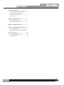
$UAL#OMPRESSOR'ATE User Manual Professional Audio Equipment IMPORTANT SAFETY INFORMATION WARNING FOR YOUR PROTECTION READ THE FOLLOWING: KEEP THESE INSTRUCTIONS HEED ALL WARNINGS FOLLOW ALL INSTRUCTIONS The symbols shown above are internationally accepted symbols that warn of potential hazards with electrical products. The lightning flash with arrowpoint in an equilateral triangle means that there are dangerous voltages present within the unit. The exclamation point in an equilateral triangle indicates that it is necessary for the user to refer to the owner’s manual. These symbols warn that there are no user serviceable parts inside the unit. Do not open the unit. Do not attempt to service the unit yourself. Refer all servicing to qualified personnel. Opening the chassis for any reason will void the manufacturer’s warranty. Do not get the unit wet. If liquid is spilled on the unit, shut it off immediately and take it to a dealer for service. Disconnect the unit during storms to prevent damage. SAFETY INSTRUCTIONS NOTICE FOR CUSTOMERS IF YOUR UNIT IS EQUIPPED WITH A POWER CORD. WARNING: THIS APPLIANCE SHALL BE CONNECTED TO A MAINS SOCKET OUTLET WITH A PROTECTIVE EARTHING CONNECTION. The cores in the mains lead are coloured in accordance with the following code: GREEN and YELLOW - Earth BLUE - Neutral THE APPARATUS SHALL NOT BE EXPOSED TO DRIPPING OR SPLASHING LIQUID AND NO OBJECT FILLED WITHI LIQUID, SUCH AS VASES, SHALL BE PLACED ON THE APPARATUS. CLEAN ONLY WITH A DRY CLOTH. DO NOT BLOCK ANY OF THE VENTILATION OPENINGS. INSTALL IN ACCORDANCE WITH THE MANUFACTURER’S INSTRUCTIONS. DO NOT INSTALL NEAR ANY HEAT SOURCES SUCH AS RADIATORS, HEAT REGISTERS, STOVES, OR OTHER APPARATUS (INCLUDING AMPLIFIERS) THAT PRODUCE HEAT. ONLY USE ATTACHMENTS/ACCESSORIES SPECIFIED BY THE MANUFACTURER. UNPLUG THIS APPARATUS DURING LIGHTNING STORMS OR WHEN UNUSED FOR LONG PERIODS OF TIME. Do not defeat the safety purpose of the polarized or grounding-type plug. A polarized plug has two blades with one wider than the other. A grounding type plug has two blades and a third grounding prong. The wide blade or third prong are provided for your safety. If the provided plug does not fit your outlet, consult an electrician for replacement of the obsolete outlet. Protect the power cord from being walked on or pinched particularly at plugs, convenience receptacles, and the point where they exit from the apparatus. Use only with the cart stand, tripod bracket, or table specified by the manufacture, or sold with the apparatus. When a cart is used, use caution when moving the cart/apparatus combination to avoid injury from tip-over. BROWN - Live As colours of the cores in the mains lead of this appliance may not correspond with the coloured markings identifying the terminals in your plug, proceed as follows: U The core which is coloured green and yellow must be connected to the terminal in the plug marked with the letter E, or with the earth symbol, or coloured green, or green and yellow. U The core which is coloured blue must be connected to the terminal marked N or coloured black. U The core which is coloured brown must be connected to the terminal marked L or coloured red. This equipment may require the use of a different line cord, attachment plug, or both, depending on the available power source at installation. If the attachment plug needs to be changed, refer servicing to qualified service personnel who should refer to the table below. The green/yellow wire shall be connected directly to the units chassis. CONDUCTOR L N LIVE NEUTRAL E EARTH GND WIRE COLOR Normal Alt BROWN BLACK BLUE WHITE GREEN/ GREEN YEL WARNING: If the ground is defeated, certain fault conditions in the unit or in the system to which it is connected can result in full line voltage between chassis and earth ground. Severe injury or death can then result if the chassis and earth ground are touched simultaneously. Refer all servicing to qualified service personnel. Servicing is required when the apparatus has been damaged in any way, such as power-supply cord or plug is damaged, liquid has been spilled or objects have fallen into the apparatus, the apparatus has been exposed to rain or moisture, does not operate normally, or has been dropped. POWER ON/OFF SWITCH: If the equipment has a Power switch, the Power switch used in this piece of equipment DOES NOT break the connection from the mains. MAINS DISCONNECT: The plug shall remain readily operable. For rackmount or installation where plug is not accessible, an all-pole mains switch with a contact separation of at least 3 mm in each pole shall be incorporated into the electrical installation of the rack or building. FOR UNITS EQUIPPED WITH EXTERNALLY ACCESSIBLE FUSE RECEPTACLE: Replace fuse with same type and rating only. MULTIPLE-INPUT VOLTAGE: This equipment may require the use of a different line cord, attachment plug, or both, depending on the available power source at installation. Connect this equipment only to the power source indicated on the equipment rear panel. To reduce the risk of fire or electric shock, refer servicing to qualified service personnel or equivalent. If connected to 240V supply, a suitable CSA/UL certified power cord shall be used for this supply. IMPORTANT SAFETY INFORMATION DECLARATION OF CONFORMITY ELECTROMAGNETIC COMPATIBILITY This unit conforms to the Product Specifications noted on the Declaration of Conformity. Operation is subject to the following two conditions: UÊ this device may not cause harmful interference, and UÊ this device must accept any interference received, including interference that may cause undesired operation. Operation of this unit within significant electromagnetic fields should be avoided. UÊ use only shielded interconnecting cables. Manufacturer’s Name: Manufacturer’s Address: dbx Professional Products 8760 S. Sandy Parkway Sandy, Utah 84070, USA declares that the product: Product name: dbx 266xs Note: Product name may be suffixed by the EU. Product option: None conforms to the following Product Specifications: Safety: IEC 60065 -01+Amd 1 EMC: EN 55022:2006 (N/A; Analog Product) IEC61000-4-2 IEC61000-4-3 IEC61000-4-4 IEC61000-4-5 IEC61000-4-6 IEC61000-4-8 IEC61000-4-11 Supplementary Information: U.K. MAINS PLUG WARNING A molded mains plug that has been cut off from the cord is unsafe. Discard the mains plug at a suitable disposal facility. NEVER UNDER ANY CIRCUMSTANCES SHOULD YOU INSERT A DAMAGED OR CUT MAINS PLUG INTO A 13 AMP POWER SOCKET. Do not use the mains plug without the fuse cover in place. Replacement fuse covers can be obtained from your local retailer. Replacement fuses are 13 amps and MUST be ASTA approved to BS1362. If you want to dispose this product, do not mix it with general household waste. There is a separate collection system for used electronic products in accordance with legislation that requires proper treatment, recovery and recycling. Private household in the 25 member states of the EU, in Switzerland and Norway may return their used electronic products free of charge to designated collection facilities or to a retailer (if you purchase a similar new one). For Countries not mentioned above, please contact your local authorities for a correct method of disposal. By doing so you will ensure that your disposed product undergoes the necessary treatment, recovery and recycling and thus prevent potential negative effects on the environment and human health. The product herewith complies with the requirements of the: Low Voltage Directive 2006/95/EC EMC Directive 2004/108/EC. RoHS Directive 2002/95/EC WEEE Directive 2002/96/EC With regard to Directive 2005/32/EC and EC Regulation 1275/2008 of 17 December 2008, this product is designed, produced, and classified as Professional Audio Equipment and thus is exempt from this Directive. Roger Johnsen Vice President of Engineering 8760 S. Sandy Parkway Sandy, Utah 84070, USA Date: November 1, 2010 European Contact: Your local dbx Sales and Service Office or Harman Music Group 8760 South Sandy Parkway Sandy, Utah 84070, USA Ph: (801) 566-8800 Fax: (801) 568-7583 Table of Contents Section 1- Introduction .......................... 1 1.1 Commom Compressor Applications .... 1 1.2 Common Gating Applications ........... 1 1.3 Service Contact Info....................... 2 1.4 Warranty....................................... 3 Section 2- Getting Started ...................... 4 2.1 Rear Panel Connections .................. 4 2.2 Front Panel Connections ................. 5 Section 3 - Making Connections .............. 8 Section 4 - Technical Support and Facts .... 9 4.1 Technical Support .......................... 9 4.2 Registration Card and User Feedback ... 9 Section A - Appendix............................... 10 A.1 Technical Specifications.................. 10 A.2 Block Diagram ............................... 11 dbx 266xs dbx 266xs Introduction Section 1 Section 1 - Introduction Congratulations on choosing the dbx 266xs Compressor/Gate. The 266xs provides traditional dbx sonic quality and performance for the working musician, DJ, studio operator or anyone who needs a friendly compressor/gate to achieve quality compression, gating and downward expansion quickly and easily. We recommend that you take a moment and read through the manual as it provides information that will assist you in using your unit to its fullest potential. 1.1 Common Compressor Applications s&ATTENINGA+ICK$RUMOR3NARE$RUM s!DDING3USTAINTO'UITAROR3YNTHESIZER3TRING3OUNDS s3MOOTHING/UTA6OCAL0ERFORMANCE s2AISINGA3IGNAL/UTOFA-IX s0REVENTING3OUND3YSTEM/VERLOAD s$IGITALTO!NALOG4RANSFERS The 266xs compressor is packed with just the right features to effectively reduce and control the dynamic range of your audio, add punch to flabby, loose sounds, or add sustain to instruments. The 266xs begins with the classic dbx compression made famous by our 160 line of compressors. Just set the 266xs Attack and Release controls to 12:00 to get the same response as those units. But there’s more. We scaled the program-dependent Attack and Release controls with dbx’s AutoDynamic™ circuitry, so that the 266xs full range of controls produce voicings that extend from slow leveling to aggressive peak limiting. 1.2 Common Gating Applications s'ATING$RY0ERCUSSIVE3OUNDSEG3NARE$RUM+ICK$RUM s'ATING3OUNDS4HAT(AVE,ONGER$ECAYEG#YMBAL0IANO s'ATING(UMOR"UZZ&ROM,IVE)NSTRUMENTSOR2ECORDED4RACKS s$OWNWARD%XPANSIONTO2EDUCE.OISE5NDER3MOOTH3OUNDSEG6OCALS7OODWINDS The 266xs gate is ready to tackle all your gating needs, whether you need to remove unwanted noise or other background sounds, tighten drum sounds, or change the characteristic envelope of an instrument. The 266xs gate provides more flexibility than traditional switch gates because it actually functions as a combination gate/expander. Where SWITCHGATESAREGENERALLYONLYSUITABLEFORALIMITEDNUMBEROFUSESEGGATINGPERCUSSION THEGATEONTHEXSACTSASAGENTLEDOWNWARDEXPANDERATLOW2ATIOSETTINGSSUITABLEFOR VOCALSGUITARMIXEDPROGRAMETCANDCANEFFECTIVELYWORKASASWITCHGATEWHENUSEDAT high Ratio settings. Refer to the following pages for suggested initial settings. These settings should suffice for TRADITIONALCOMPRESSINGANDGATINGREQUIREMENTS(OWEVERTHEXSCANACCOMPLISHMANY more changes to sound quality. We recommend that you experiment with the 266xs controls; take our suggested settings and run with them, try totally different settings, and try unorthodox combinations of compressor and gating controls. You might be surprised at what you hear. Best of all, you may create the perfect sound quality for your needs. 1 Section 1 Introduction dbx 266xs 1.3 Service Contact Info If you require technical support, contact dbx Technical Support. Be prepared to accurately DESCRIBETHEPROBLEM+NOWTHESERIALNUMBEROFYOURDEVICETHISISPRINTEDONASTICKER attached to the chassis. If you have not already taken the time to fill out your warranty registration card and send it in, please do so now. You may also register online at www.dbxpro.com. Before you return a product to the factory for service, we recommend you refer to the manual. -AKESUREYOUHAVECORRECTLYFOLLOWEDINSTALLATIONSTEPSANDOPERATIONPROCEDURES&ORFURTHER TECHNICALASSISTANCEORSERVICEPLEASECONTACTOUR4ECHNICAL3UPPORT$EPARTMENTAT ORVISITWWWDBXPROCOM)FYOUNEEDTORETURNAPRODUCTTOTHEFACTORYFORSERVICE YOU-534FIRSTCONTACT4ECHNICAL3UPPORTTOOBTAINA2ETURN!UTHORIZATION.UMBER .ORETURNEDPRODUCTSWILLBEACCEPTEDATTHEFACTORYWITHOUTA2ETURN!UTHORIZATION.UMBER Please refer to the Warranty information on the following page, which extends to the first end-user. After expiration of the warranty, a reasonable charge will be made for parts, labor, and packing if you choose to use the factory service facility. In all cases, you are responsible for transportation charges to the factory. dbx will pay return shipping if the unit is still under warranty. 5SETHEORIGINALPACKINGMATERIALIFITISAVAILABLE-ARKTHEPACKAGEWITHTHENAMEOFTHE SHIPPERANDWITHTHESEWORDSINRED$%,)#!4%).3425-%.4&2!'),%!LSOWRITETHE2ETURN !UTHORIZATION.UMBER2!ONTHEOUTSIDEOFTHEBOXINACONSPICUOUSLOCATION)NSURETHE package properly. Ship prepaid, not collect. Do not ship parcel post. 2 dbx 266xs Introduction Section 1 1.4 Warranty This warranty is valid only for the original purchaser and only in the United States. 1. The warranty registration card that accompanies this product must be mailed within 30 days after purchase date to validate this warranty. You can also register online at www.dbxpro.com. Proof-of-purchase is considered to be the responsibility of the consumer. A copy of the original purchase receipt must be provided for any warranty service. 2. dbx warrants this product, when bought and used solely within the U.S., to be free from defects in materials and workmanship under normal use and service. 3. dbx liability under this warranty is limited to repairing or, at our discretion, replacing defective materials that show evidence of defect, provided the product is returned to dbx 7)4(2%452.!54(/2):!4)/.FROMTHEFACTORYWHEREALLPARTSANDLABORWILLBECOVEREDUP TOAPERIODOFTWOYEARS!2ETURN!UTHORIZATIONNUMBERMUSTFIRSTBEOBTAINEDFROMDBX4HE company shall not be liable for any consequential damage as a result of the product’s use in any circuit or assembly. 4. dbx reserves the right to make changes in design or make additions to or improvements upon this product without incurring any obligation to install the same additions or improvements on products previously manufactured. 5. The foregoing is in lieu of all other warranties, expressed or implied, and dbx neither ASSUMESNORAUTHORIZESANYPERSONTOASSUMEONITSBEHALFANYOBLIGATIONORLIABILITYIN connection with the sale of this product. In no event shall dbx or its dealers be liable for special or consequential damages or from any delay in the performance of this warranty due to causes beyond their control. 3 Section 2 Getting Started dbx 266xs Section 2 - Getting Started 2.1 Rear Panel Connections IEC Power Cord Receptacle 4HEDBXXSCOMESWITHAPOWERSUPPLYTHATWILLACCEPTVOLTAGESRANGINGFROM66 ATFREQUENCIESFROM(Z(Z!N)%#CORDISINCLUDED%5VERSIONACCEPTS66AT FREQUENCIESFROM(Z(Z 7!2.).'"ESURETOVERIFYYOURACTUALLINEVOLTAGEISTHESAME as the voltage level printed below the AC power receptacle. Connection to an inappropriate power source may result in extensive damage which is not covered by the warranty. #AUTION.EVERREMOVETHECOVER4HEREARENOUSERSERVICEABLEPARTSINSIDE INPUT Jacks (CHANNEL 1 and 2) 5SEv423PHONEPLUGSORMALE8,2PLUGSTOCONNECTTHESEINPUTSTOYOURSOURCE4HE XS).054JACKSACCEPTEITHERBALANCEDORUNBALANCEDSIGNALS)NPUTIMPEDANCEISKΩ. OUTPUT Jacks (CHANNEL 1 and 2) 4HE/54054JACKSACCEPTv423BALANCEDORUNBALANCEDPHONEPLUGSORFEMALE8,2PLUGS -AXIMUMOUTPUTSIGNALLEVELISD"U)NTHED"USETTINGTHEBALANCEDOUTPUT impedance is 100Ω, and the unbalanced output impedance is 50Ω)NTHED"6SETTINGTHE balanced output impedance is 1kΩ and the unbalanced output impedance is 500Ω. OPERATING LEVEL Switch 4HISSWITCHSELECTSBETWEENAD"6ANDD"UNOMINALOPERATINGLEVEL7HENTHESWITCHIS in the ).POSITIONAD"6OPERATINGLEVELISSELECTED7HENITISINTHE/54 position, a D"UOPERATINGLEVELISSELECTED SIDECHAIN INSERT Jack This jack accepts 1/4” TRS phone plugs and provides a connection to the 266xs detector path. 4HE2).'ACTSASA3ENDCARRYINGABUFFEREDVERSIONOFTHESIGNALPRESENTATTHEXS).054 jack, at an impedance of 2kΩ. The TIP acts as a Return for equipment to feed the 266xs DETECTORCIRCUITRYSUCHASANEQUALIZERFORDEESSINGORFREQUENCYSENSITIVEGATINGCOMPRESsion. You can also drive the 266xs Sidechain input with the output of most equipment, by using a 1/4” mono phone plug. Input Impedance is greater than 10kΩ. NOTE: When a cable is plugged into this jack, it automatically breaks the connection from THE).054JACKTOTHEXSDETECTIONCIRCUITRY 4 dbx 266xs Getting Started Section 2 2.2 Front Panel Connections STEREO COUPLE Switch 4HISSWITCHSETSTHEXSFOR3TEREOOR$UAL-ONOOPERATION0RESSTHE34%2%/#/50,%SWITCH in for stereo operation where Channel 1 becomes the master controller for both channels. All OF#HANNELSCONTROLSSWITCHESAND,%$SWILLBEDISABLEDEXCEPTFORTHE#HANNEL'!). 2%$5#4)/.METERSINCE#HANNELISTHESLAVE 7ITHTHE34%2%/#/50,%SWITCHOUTTHEUNITFUNCTIONSASTWOSEPARATEMONOCOMPRESSOR gates, each with its own independent controls. 4HE34%2%/#/50,%SWITCHLIGHTSREDWHENTHEXSISSTEREOCOUPLED BYPASS Switch Press this switch in to bypass the front panel controls, effectively canceling the function and processing effect of the 266xs compression, gating and gain settings. The input signal is still PRESENTATTHEXS/UTPUTBUTISNOWUNALTEREDBYTHEXSCONTROLS"90!33ISESPECIALLY USEFULFORMAKINGCOMPARISONSBETWEENPROCESSEDANDUNPROCESSEDSIGNALS.OTETHATWITH STEREOOPERATION34%2%/#/50,%SWITCHPRESSEDINTHE#HANNEL"90!33SWITCHCONTROLS both channels. The BYPASS switch lights red when BYPASS mode is active. GAIN REDUCTION (dB) Meter This meter displays the amount of signal attenuated from the input signal by the 266xs #OMPRESSOROR%XPANDER'ATE7HENTHE#OMPRESSORAND%XPANDER'ATEAREBOTHACTIVETHE meter displays the maximum amount of gain reduction for whichever function is greater #OMPRESSOROR%XPANDER'ATE OUTPUT GAIN (dB) Control 4HISCONTROLSETSTHEOVERALLGAINOFTHEXSFROMD"TOD"4HE/54054'!). CONTROLISESPECIALLYUSEFULTOCOMPENSATEFORTHE2-3LEVELDECREASEWHICHRESULTSFROMTHE 266xs dynamic processing effects. After you adjust the 266xs controls for the desired amount OFCOMPRESSIONSETTHE/54054'!).TOADDTHESAMEAMOUNTOFGAINTHATISSHOWNONTHE '!).2%$5#4)/.METERS&OREXAMPLEIFTHEAVERAGEAMOUNTOFGAINREDUCTIONSHOWNONTHE METERSISD"THENSETTINGTHE/54054'!).CONTROLTOD"WILLCOMPENSATEFORTHED" average level reduction at the output. NOTE: 4HEXS#OMPRESSORAND%XPANDER'ATECONTROLSETTINGSAREINTERACTIVEANDCAN affect gain, so watch your playback levels. NOTE: 3ETTINGTHE#OMPRESSOR2!4)/TOWILLTURNTHE#OMPRESSOROFFREGARDLESSOFTHE SETTINGOFTHE#OMPRESSOR4(2%3(/,$CONTROLAND"%,/7/6%2%!39!"/6%,%$STATUS 3ETTINGTHE#OMPRESSOR4(2%3(/,$CONTROLTOD"WILLPREVENTALLBUTTHEHIGHESTLEVEL peaks from being compressed. 5 Section 2 Getting Started dbx 266xs OVEREASY® Switch $EPRESSTHISSWITCHTOSELECTTHE/VER%ASYCOMPRESSIONCHARACTERISTIC4HEAMBER4(2%3(/,$ ,%$TURNSONWHENTHESIGNALISINTHE/VER%ASYREGION7HENTHESWITCHISOUTTHEXS OPERATESASAHARDKNEECOMPRESSORANDTHEAMBER,%$DOESNOTLIGHT Compressor THRESHOLD Control and LEDs (BELOW/OVEREASY/ABOVE) !DJUSTTHISCONTROLTOSETTHETHRESHOLDOFCOMPRESSIONFROMD"TOD")NHARDKNEE mode, the threshold of compression is defined as the point above which the output level no longer changes on a 1:1 basis with changes in the input level. )N/VER%ASYMODETHETHRESHOLDOFCOMPRESSIONISDEFINEDASTHEMIDDLEOFTHE/VER%ASY threshold region, that is, “half-way” into compression. 4HETHREE4(2%3(/,$,%$SINDICATETHERELATIONSHIPOFTHEINPUTSIGNALLEVELTOTHETHRESHOLD OFCOMPRESSION4HEGREEN,%$LIGHTSWHENTHESIGNALIS"%,/7THRESHOLDTHERED,%$LIGHTS WHENTHESIGNALISABOVETHRESHOLDANDTHEYELLOW,%$LIGHTSWHENTHE/6%2%!39SWITCHIS DEPRESSEDANDTHEINPUTSIGNALISINTHE/6%2%!39RANGE 4HEXS/VER%ASYCOMPRESSIONPERMITSEXTREMELYSMOOTHNATURALSOUNDINGCOMPRESSION without artifacts, due to the gradual change of compression around the threshold. With /VER%ASYCOMPRESSIONINPUTSIGNALSBEGINTOGRADUALLYACTIVATETHEXSINTERNALGAIN CHANGECIRCUITRYASTHEYAPPROACHTHE4(2%3(/,$REFERENCELEVEL4HEYDONOTGETFULLYPROCESSEDBYTHE2!4)/!44!#+AND2%,%!3%CONTROLSUNTILTHEYHAVEPASSEDSOMEWHATABOVE THE4(2%3(/,$REFERENCELEVEL!STHESIGNALLEVELPASSESTHE4(2%3(/,$LEVELPROCESSING increases until it is fully processed to the extent determined by the control settings. In hard-knee mode, the 266xs can provide abrupt compression effects as well as hard-limiting APPLICATIONS.OTETHATWHENINHARDKNEEMODETHEAMBER,%$WILLNOTLIGHTASTHEINPUT SIGNALPASSESACROSSTHETHRESHOLD4HESIGNALISEITHERBEINGCOMPRESSEDOVERTHRESHOLDORIT ISNOTBEINGCOMPRESSEDUNDERTHRESHOLD NOTE:%VENTHOUGHNOINPUTSIGNALISBEINGAPPLIEDITISNORMALFORTHE,%$STOFLICKERON when the power is applied or removed. Compressor RATIO Control Adjust this control to set the amount of compression applied to the input signal. Clockwise ROTATIONOFTHISCONTROLINCREASESTHECOMPRESSIONRATIOFROMNOCOMPRESSIONUPTO∞:1 WHERETHECOMPRESSORCANBECONSIDEREDTOBEAPEAKLIMITERESPECIALLYWITHFASTER!44!#+ SETTINGS 7HENANINPUTISABOVETHE4(2%3(/,$SETTINGREFERENCELEVELTHE2!4)/SETTINGDETERMINES the number of decibels by which the input signal must increase in level to produce a 1dB increase in the signal level at the output of the 266xs. A setting of 2:1 indicates an input/ OUTPUTRATIOWHEREINAD"INCREASEINSIGNALABOVETHRESHOLDWILLPRODUCEAD"INCREASEIN output signal. A setting of :1 indicates that an infinite increase in input level would be required to raise the output level by 1dB. 6 dbx 266xs Getting Started Section 2 Compressor ATTACK and RELEASE Control 4HE!44!#+CONTROLSETSTHEAMOUNTOFTIMEITTAKESTHEXSTOBEGINCOMPRESSINGASIGNAL ONCETHEDETECTORHASSENSEDASIGNALABOVETHRESHOLD4HE!44!#+RANGEISFROM&!34FORA TIGHTERANDMORENOTICEABLECOMPRESSIONEFFECTWITHVERYLITTLEOVERSHOOTTO3,/7FORMORE DELAYEDGRADUALCOMPRESSION!VERYFAST!44!#+SETTINGWILLCAUSETHEXSTOACTLIKEA PEAKLIMITEREVENTHOUGH2-3DETECTIONCIRCUITRYISUSED3LOWER!44!#+SETTINGSCAUSETHE XSTOACTLIKEAN2-3ORAVERAGINGDETECTINGCOMPRESSORLIMITER 4HE2%,%!3%CONTROLSETSHOWFASTTHECOMPRESSIONCIRCUITRETURNSTHEINPUTTOITSORIGINAL LEVEL4HE2%,%!3%RATEISFROM&!34WHERECOMPRESSIONFOLLOWSTHEENVELOPEOFTHEPROGRAM MATERIALVERYTIGHTLYTO3,/7FORVERYSMOOTHCOMPRESSION There is no absolute rightWAYTOSETTHE!44!#+AND2%,%!3%CONTROLS(OWEVERINGENERAL you will want them set slow enough to avoid pumping or breathing sounds caused when background sounds are audibly modulated by the dominant signal energy, yet the release must be fast enough to avoid suppression of the desired signal after a sudden transient or loud NOTEHASDECAYED&ORLOWFREQUENCYTONESEGBASSGUITARSET2%,%!3%AND!44!#+TO 2:00 or slower. NOTE:!44!#+AND2%,%!3%CONTROLSOPERATETOGETHERANDINCONJUNCTIONWITHTHE2!4)/ control. Changing one control may necessitate changing another setting. AUTO Switch 4HISSWITCHOVERRIDESBOTHTHE!44!#+AND2%,%!3%CONTROLSANDENABLESPRESETPROGRAM dependent attack and release times. These times are derived from the input signal and conTINUOUSLYCHANGETOMATCHITSDYNAMICS%NABLINGTHIS!54/&UNCTIONDUPLICATESTHEhCLASSIC dbx sound” of the 266xs forerunners which have become standards in the industry. Expander/Gate THRESHOLD Control and LEDs (BELOW/ABOVE) NOTE:4HE%XPANDER'ATEISOFFWHENTHE%XPANDER'ATE4(2%3(/,$ISSETTO/&& Adjusting this control sets the level at which the gate will open and allow the signal at the INPUTTOPASSTHROUGHTOTHEOUTPUT4URNINGTHEKNOBFULLYCOUNTERCLOCKWISETO/&&ALLOWS the gate to pass all signals unattenuated, effectively bypassing the gate. Turning the knob FULLYCLOCKWISECAUSESTHEGATETOATTENUATEINPUTSIGNALSBELOWD"U4HEDEPTHOFATTENUATIONDEPENDSONTHESETTINGOFTHE%XPANDER'ATE2!4)/CONTROL 4HETWO%XPANDER'ATE,%$SINDICATETHERELATIONSHIPOFTHEINPUTSIGNALLEVELTOTHETHRESHOLDSETTING4HERED,%$LIGHTSWHENTHESIGNALIS"%,/7THRESHOLDTHEGREEN,%$LIGHTSWHEN the signal is !"/6% threshold. 7 Section 3 Making Connections dbx 266xs Expander/Gate RATIO Control This control sets the amount of attenuation applied to the input signal once it is below the THRESHOLDFROMGENTLEDOWNWARDEXPANSIONAPPROPRIATEFORMIXEDPROGRAMVOCALSETCTOA HARDGATINGEFFECTWHICHCANBEUSEFULFORPERCUSSION&AIRLYLOW2!4)/ANDHIGHER %XPANDER'ATE4(2%3(/,$SETTINGSWORKBESTFORDOWNWARDEXPANSIONWHEREASHIGHER2!4)/ SETTINGSCLOCKWISETOWARDS-!8WORKBESTFORGATING)FASETTINGPRODUCESUNDESIRABLE PUMPINGREADJUSTTHE%XPANDER'ATE2!4)/OR4(2%3(/,$SETTING NOTE:4HEATTACKANDRELEASERATEOFTHE%XPANDER'ATEAREPROGRAMDEPENDENTVERYFAST FORTRANSIENTMATERIALEGPERCUSSIONANDSLOWERFORMATERIALWITHSLOWATTACKEG VOCALS NOTE: Fast gating of sustained low frequency signals can result in “chattering”. To ELIMINATEANYhCHATTERINGvSIMPLYADJUSTTHE2!4)/CONTROL4HEPROPER4(2%3(/,$SETTING WILLALSOMINIMIZEFALSETRIGGERINGANDhCHATTERINGv Section 3 - Making Connections The 266xs can be used with any line-level device. Some common examples include mixing consoles, electronic musical instruments, patch bays, and signal processors. For all connections, refer to the following steps: 4URN/FFALLEQUIPMENTBEFOREMAKINGANYCONNECTIONS -OUNTTHEXSINA5RACKSPACEOPTIONAL 4HEXSREQUIRESONERACKSPACEHEIGHTANDRACKSPACEWIDTH)TCANBE mounted above or below anything that doesn’t generate excessive heat, since it REQUIRESNOSPECIALVENTILATION!MBIENTTEMPERATURESSHOULDNOTEXCEED&# when equipment is powered. -AKECONNECTIONSVIAv423PHONEOR8,2JACKSACCORDINGTOYOURREQUIREMENTS Typical patch points include: a mixer’s channel or subgroup inserts when using the 266xs on individual instruments or tracks; the mixer’s main outputs when mixing; an instrument preamp’s effects loop when using the 266xs for guitar or bass; main outs OFASUBMIXERIEKEYBOARDMIXERASTHESIGNALISSENTTOMAINMIXERBETWEENA DAT’s output and an analog cassette input. When using a chain of processors, the 266xs may be placed either before or after effects or dynamics processors. We recommend you use common sense and experiment with different setups to see which one provides the best results for your needs. #ONNECTTHE!#POWERCORDSHIPPEDWITHTHEUNITTOTHEXSREARPANEL 0/7%2CONNECTORANDANAPPROPRIATE!#POWERSOURCETOTURNTHEUNIT/. 8 dbx 266xs Technical Support and Facts Section 4 Section 4 - Technical Support and Facts 4.1 Technical Support The 266xs is an all-solid-state product with components chosen for high performance ANDEXCELLENTRELIABILITY%ACHXSISTESTEDBURNEDINANDCALIBRATEDATTHEFACTORY and should require no internal adjustment of any type throughout the life of the unit. We recommend that your 266xs be returned to the factory only after referring to the manual and consulting with dbx Customer Service. /URPHONENUMBER&AXNUMBERANDADDRESSARELISTEDONTHEBACKCOVEROFTHISMANUAL When you contact dbx Customer Service, be prepared to accurately describe the problem. +NOWTHESERIALNUMBEROFYOURUNIT4HISISPRINTEDONASTICKERATTACHEDTOTHE side panel of the unit. NOTE: 0LEASEREFERTOTHETERMSOFYOUR,IMITED4WO9EAR3TANDARD7ARRANTYWHICHEXTENDS to the first end user. After the warranty expires, a reasonable charge will be made for parts, labor, and packing if you choose to use the factory service facility. In all cases, you are responsible for shipping charges to the factory. dbx will pay return shipping if the unit is still under warranty. 3HIPPING)NSTRUCTIONS5SETHEORIGINALPACKINGMATERIALIFITISAVAILABLE-ARKTHE PACKAGEWITHTHENAMEOFTHESHIPPERANDWITHTHESEWORDSINRED$%,)#!4%).3425-%.4 &2!'),%)NSURETHEPACKAGEPROPERLY3HIPPREPAIDNOTCOLLECT$ONOTSHIPPARCELPOST 4.2 Registration Card and User Feedback We appreciate your feedback. After you have an opportunity to use your new 266xs, please complete the Registration Card and return it. 9 Section A dbx 266xs Appendix Section A - Appendix A.1 Technical Specifications .OTED"U62-3 3PECIFICATIONSARESUBJECTTOCHANGE INPUT (Balanced or Unbalanced): )MPEDANCE KΩ -AX,EVEL D"U OUTPUT (Impedance Balanced): )MPEDANCE -AX,EVEL "ALANCED Ω Unbalanced: 50Ω -10dBu: Balanced: 1kΩ Unbalanced: 500Ω D"UD"MINTOΩ) SIDECHAIN INSERT: )NPUT)MPEDANCE /UTPUT)MPEDANCE -AX)NPUT,EVEL -AX/UTPUT,EVEL KΩ KΩ D"U D"U FREQUENCY RESPONSE: &LAT "ANDWIDTH (ZK(ZD" (ZK(ZD" SYSTEM PERFORMANCE: $ISTORTION.OISE )NTERMODULATION$ISTORTION .OISE $YNAMIC2ANGE )NTERCHANNEL#ROSSTALK #OMMON-ODE2EJECTION 3TEREO#OUPLING ANYAMOUNTOFCOMPRESSIONATK(Z 3-04% D"UNWEIGHTEDK(ZMEASUREMENTBANDWIDTH D"UNWEIGHTED D"(ZTOK(Z D"TYPICALLYD" K(Z 4RUE2-30OWER3UMMING© THRESHOLD: #OMPRESSOR %XPANDER'ATE RATIO: Compressor: %XPANDER'ATE ATTACK Time: Compressor: %XPANDER'ATE RELEASE Time: Compressor: %XPANDER'ATE 10 D"U /VER%ASYORHARDKNEED"UTOD"U D"UTOD"U 1:1 to Infinity:1 TO Scalable Program-Dependent AutoDynamic™ «3EC Scalable Program-Dependent AutoDynamic™ 0ROGRAM$EPENDENT POWER SUPPLY: /PERATING6OLTAGE Power Consumption: /PERATING4EMPERATURE 6!#6!#(Z6!#(Z 15 Watts ª&TOª&ª#TOª# PHYSICAL: .ET7EIGHT 3HIPPING7EIGHT $IMENSIONS LBSKG LBSKG vCM(XvCM$XvCM7 dbx 266xs Appendix Section A A.2 Block Diagram 11 4PVUI4BOEZ1BSLXBZr4BOEZ6UBI 1IPOF r'BY Int’l Fax: (801) 568-7583 Questions or comments? Contact us at www.dbxpro.com Printed in China !