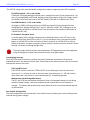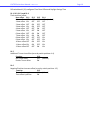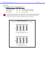
1
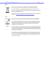
CLKTCD Series Analog Clocks
User Manual
CLKTCD Series User Manual – Rev. 2.0.1 Page 2 Table of Contents Forward ............................................................................................................................................ 5 Disclaimer .............................................................................................................................................................................. 5 Copyrights ............................................................................................................................................................................. 5 Trademarks ........................................................................................................................................................................... 5 Icons Used In This Manual .................................................................................................................................................... 5 Printing .................................................................................................................................................................................. 5 Compliance ....................................................................................................................................... 6 CE Marking ............................................................................................................................................................................ 6 FCC Statement ....................................................................................................................................................................... 6 WEEE ..................................................................................................................................................................................... 7 RoHS ...................................................................................................................................................................................... 7 Introduction ..................................................................................................................................... 8 IRIG‐B .................................................................................................................................................................................... 8 SMPTE ................................................................................................................................................................................... 8 Features ................................................................................................................................................................................ 8 General Use Precautions .................................................................................................................. 9 Health and Safety .................................................................................................................................................................. 9 Unpacking and Installation ............................................................................................................. 10 Supplied (Ship Kit) ............................................................................................................................................................... 10 AC Version ........................................................................................................................................................................... 11 Mounting ............................................................................................................................................................................. 12 12” Models ...................................................................................................................................................................... 12 12” Dual Face Model ....................................................................................................................................................... 13 Operating Environment .................................................................................................................. 14 Status LED ........................................................................................................................................................................... 14 Correction Behavior ............................................................................................................................................................ 14 Hand Position ...................................................................................................................................................................... 15 Time Zone Offsets ............................................................................................................................................................... 15 Daylight Saving Time ........................................................................................................................................................... 15 Pre 2007 Standard – U.S.A. and Canada ......................................................................................................................... 16 Post 2006 Standard – U.S.A. and Canada ........................................................................................................................ 16 EU Standard – European Union ....................................................................................................................................... 16 Freewheeling Accuracy ....................................................................................................................................................... 16 TCXO and RTC circuit ....................................................................................................................................................... 16 Maintenance‐free Rechargeable Battery ........................................................................................................................ 16 Configuration ................................................................................................................................. 18 DIP Switches ........................................................................................................................................................................ 18 S1.1, S1.2, S1.3, and S1.4 ................................................................................................................................................ 19 S1.5 .................................................................................................................................................................................. 19 S1.6 .................................................................................................................................................................................. 19 S1.7 and S1.8 ................................................................................................................................................................... 20 S2.1 and S2.2 ................................................................................................................................................................... 21 S2.3 and S2.4 ................................................................................................................................................................... 21 S2.5 .................................................................................................................................................................................. 21 S2.6 .................................................................................................................................................................................. 21 S2.7 .................................................................................................................................................................................. 21 S2.8 .................................................................................................................................................................................. 21 Hand Calibration ................................................................................................................................................................. 22 Default Configuration .......................................................................................................................................................... 23 Reset Configuration to Factory‐Default .......................................................................................................................... 23 CLKTCD Series User Manual – Rev. 2.0.1 Page 3 CLKTCD‐Set ..................................................................................................................................... 24 Installation .......................................................................................................................................................................... 24 USB drivers...................................................................................................................................................................... 25 Using CLKTCD‐Set ............................................................................................................................................................... 26 Time Zone Offset ............................................................................................................................................................ 27 Daylight Saving Time ....................................................................................................................................................... 27 Time Code Settings ......................................................................................................................................................... 28 Set Date Time ................................................................................................................................................................. 28 Clock Hand Position ........................................................................................................................................................ 29 Sweep mode ............................................................................................................................................................... 29 Step mode ................................................................................................................................................................... 29 To adjust the hands ........................................................................................................................................................ 29 Specifications ................................................................................................................................. 30 Communications I/O ........................................................................................................................................................... 30 Power Requirements .......................................................................................................................................................... 30 AC .................................................................................................................................................................................... 30 Internal Battery Circuit ....................................................................................................................................................... 31 Maintenance Free Rechargeable Battery ....................................................................................................................... 31 Operating/Storage Temperature and Humidity ................................................................................................................. 31 Size and Weight .................................................................................................................................................................. 31 Troubleshooting ............................................................................................................................. 32 The time is incorrect. .......................................................................................................................................................... 32 Not displaying the correct [local] time. .............................................................................................................................. 32 Displayed time [local] is off a small amount. ...................................................................................................................... 33 DST is not properly negotiated. .......................................................................................................................................... 33 The clock hands are not moving and the red status LED is off. .......................................................................................... 33 Care and Cleaning ........................................................................................................................... 34 Job Site Precautions ............................................................................................................................................................ 34 Stainless Steel Case ............................................................................................................................................................. 34 Compatible Cleaners and Polish ......................................................................................................................................... 34 Washing to Minimize Scratching ........................................................................................................................................ 34 Minimize Hairline Scratches ............................................................................................................................................... 35 "Don't" ‐ Very Important .................................................................................................................................................... 35 Cleaning the Lens ................................................................................................................................................................ 35 Foreign Substance Removal ................................................................................................................................................ 35 Limited Warranty ........................................................................................................................... 36 Exclusions ........................................................................................................................................................................... 36 Limitations .......................................................................................................................................................................... 36 Exclusive Remedies ............................................................................................................................................................. 36 Service Information ........................................................................................................................ 37 RMA Policy .......................................................................................................................................................................... 37 Contacting Us ...................................................................................................................................................................... 37 CLKTCD Series User Manual – Rev. 2.0.1 This page intentionally left blank. Page 4 CLKTCD Series User Manual – Rev. 2.0.1 Page 5 Forward Disclaimer The material in this document is for information only and subject to change without notice. While reasonable efforts have been made in the preparation of this document to assure its accuracy, Masterclock, Inc. assumes no liability resulting from errors or omissions in this document or from the use of the information contained herein. Masterclock, Inc. reserves the right to make changes or revisions in the product design or the product manual without reservation and without obligation to notify any person of such revisions and changes Copyrights Copyright © 2011 Masterclock, Inc. All rights reserved. No part of this publication may be reproduced, stored in a retrieval system or transmitted in any form or by any means, electronic, mechanical, photocopying, recording or otherwise, without the prior written consent of Masterclock, Inc. Trademarks Microsoft, Windows 2000, Windows XP and Windows 7 are registered trademarks of Microsoft Corporation. Other trademarks mentioned in this manual are the property of their respective owners. Icons Used In This Manual Caution: This icon signifies a potential hazard, and gives tips on how to avoid them. Important Information: This icon indicates to an important step that must be followed.
Technical Note: This icon describes technical terms and actions. Helpful Hint: This icon suggests the general setup and practice. Printing While optimized for onscreen viewing, the pages of this manual are formatted for printing on 8 1/2” x 11” and A4 sized paper, giving you the option to print the entire manual or just a specific page or section. CLKTCD Series User Manual – Rev. 2.0.1 Page 6 Compliance CE Marking Electromagnetic Compatibility 89/336/EEC ; 92/31/EC ; 93/68/EEC ; 2004/108/EC Tested and Conforms to the following EMC standards : EN61000‐4‐2:2000 (Electrostatic Discharge) EN61000‐4‐3 (RF Immunity) EN61000‐4‐4 (Fast Transient Common Mode) EN61000‐4‐5 (Surge)EN61000‐4‐6 (RF Injection Common Mode) EN61000‐4‐8: 1993 (Power Frequency Magnetic Field) EN61000‐4‐11 (Voltage Dips) EN61000‐6‐3:2001 (EMC Emissions Generic Commercial) EN55022:1998+A1:2000 +A2:2003 CISPR22 EN61000‐3‐2:2000 (Harmonic Current Emission) EN61000‐3‐3:1995 + A1:2001 (Voltage Fluctuations and Flicker) Low voltage directive 2006/95/EC Tested and Conforms to the following Safety standards: EN60950‐1:2001 (Safety of Information Technology Equipment) Certificated By CELAB® www.celab.com UCN = 900548001073 FCC Statement This device complies with Part 15 of the FCC Rules and found to comply with the limits for a Class B digital device. These limits are designed to provide reasonable protection against harmful interference in a commercial/residential installation. Operation is subject to the following two conditions: (1) This device may not cause harmful interference, and (2) this device must accept any interference received, including interference that may cause undesired operation CLKTCD Series User Manual – Rev. 2.0.1 Page 7 WEEE Waste Electrical and Electronic Equipment Directive (WEEE) 2002/95/EC The CLKTCD models are considered WEEE Category 9 (Monitoring and Control Instruments Equipment) as defined by the WEEE Directive and therefore fall within the scope of the WEEE Directive. For more information about Masterclock’s WEEE compliance and recycle program, please visit: http://www.masterclock.com/rohs_compliance.php RoHS Compliant by Exemption Restriction of the Use of Certain Hazardous Substances Directive 2002/95/EC The RoHS directive covers the same scope of electrical and electronic equipment that are under the WEEE directive, except that Category 8, Medical Devices, and Category 9, Monitoring and Control Instruments, which are under WEEE, are excluded from the RoHS directive. The time display product CLKTCD fall under the category of Monitoring and Control Instruments Equipment (Category 9 as defined in Annex 1A of WEEE 2002/96/EC Directive) which is excluded from the RoHS directive 2002/95/EC (reference Article 2, paragraph 1) requirements. These products are manufactured using lead in the soldering process as allowed for items excluded from the RoHS directive. These units are RoHS Compliant only in that they are excluded from the RoHS directive under Category 9, Monitoring and Control Instruments. CLKTCD Series User Manual – Rev. 2.0.1 Page 8 Introduction The CLKTCD is a precision analog clock containing a stepper motor drive and advanced microprocessor controlled electronics. IRIG‐B Defined by the Range Commanders Council, U.S. Army White Sands Missile Range. IRIG (Inter‐
range Instrumentation Group) is used by military, government, power industry and many other commercial and industrial applications. The CLKTCD decodes IRIG‐B in both a 1 kHz modulated (IRIG‐B1) and un‐modulated/pulse width coded/DC level shifted (IRIG‐B0) format. All formats of IRIG‐B time code decoded by the CLKTCD use the time of year information BCD (Binary Coded Decimal). All formats of IRIG‐B time code decoded by the CLKTCD also use the extended year/date and time zone information in the control functions as defined by the IEEE 1344 specification. SBS (Straight Binary Seconds) information is not decoded. Manchester format/encoding is not supported. The CLKTCD can be configured for world‐wide time zone offset and automatic DST (Daylight Saving Time) adjustment and allows for reliable, accurate and maintenance free operation. Use of the automatic DST feature requires that the clock be enabled to accept the time code date encoding, using the USB port and CLKTCD‐Set (Clock Time Code Display) USB Configuration Utility (i.e. Windows software application). The time code reference must provide date encoding in the control bits/fields to the Masterclock/Leitch date encoding standard for SMPTE or the IEEE‐1344 year encoding for IRIG‐B. SMPTE Society of Motion Picture and Television Engineers format is available in frame rates of 24, 25, and 30 frames second. The CLKTCD time code clock supports all three formats. All formats of SMPTE time code decoded by the CLKTCD use the full date information in the user bits as defined by Leitch, Inc. The CLKTCD does not support decoding of SMPTE drop‐frame, reverse running, VITC, NTSC, color frame, blackburst or other video time code formats and synchronization options. Please refer to the “Specifications” section of this document for additional details on each model. For available options, visit Masterclock’s website: www.masterclock.com Features • RTC (Real Time Clock) backup retains time during loss of power or reference. • Self‐correcting hands once power and/or Time Code reference is established. • Time zone offsets (to one second resolution) supports any biasing requirements. • DST configuration. • TCXO (Temperature Compensated Crystal Oscillator) for +/‐ 1 min year accuracy with no reference in (freewheeling). • All configuration settings retained in non‐volatile flash memory. • Second Hand with sweep or step option. • Self‐correcting hands after loss of power and/or time code reference and DST changes. • Status LED (Light Emitting Diode) on clock face, located at the 6 o’clock position.
CLKTCD Series User Manual – Rev. 2.0.1 Page 9 General Use Precautions Do not expose this clock to temperatures outside the range of 32° to 140°F (0° to 60°C). Placing your device in an environment that is too cold or humid may damage the unit. Do not place heavy objects on top of this clock or use excessive force on it. Never use benzene, paint thinners, detergent or other chemical products to clean the outside of this clock. Such products will disfigure and discolor the casing. Please refer to the “Care and Cleaning” section of this document for details on cleaning and recommended products. The Masterclocks's CLKTCD clock warranty may be void as a result of the failure to respect the precautions stated above. Health and Safety This clock generates, uses, and can radiate radio frequency energy and, if not installed and used in accordance with the instructions, may cause harmful interference to radio communications. There is no guarantee that interference will not occur in a particular installation. If this clock does cause harmful interference to radio or television reception, which can be determined by removing power from the clock, the user is encouraged to try to correct the interference by one or more of the following measures: 1. Connect the AC power cord into an outlet on a different circuit than other devices. 2. Increase the physical distance between the clock and other devices. 3. Contact technical support. This CLKTCD analog clock has been tested and found to comply with the limits for a Class B digital device, pursuant to Part 15 of the FCC Rules. These limits are designed to provide reasonable protection against harmful interference in a residential installation. Only qualified persons are authorized to carry out maintenance on this device. Read this User’s Manual carefully, and follow the correct procedure when setting up the device. Do not open your Masterclock product or attempt to disassemble or modify it. Never insert any metallic object into the clocks case, doing so increases the risk of electrical shock, short circuiting, fire or personal injury. Never expose your clock to rain or use it near water or in damp or wet conditions. Never place objects containing liquids on or near this clock, as they may spill into its openings increasing the risk of electrical shock, short circuiting, fire or personal injury. CLKTCD Series User Manual – Rev. 2.0.1 Page 10 Unpacking and Installation Supplied (Ship Kit) The list below is for illustration purposes. Refer to your sales order for actual items shipped. • CLKTCD analog clock • Mounting bracket with retaining screw • CD‐ROM (CLKTCD‐Set, USB Configuration Utility and User Manual) • Power cord CLKTCD12 Powder coated steel case 12 hour faceplate CLKTCD12‐HM
Powder coated steel case 24 hour faceplate CLKTCD12‐DF Powder coated steel case 12/24 hour faceplate CD‐ROM IEC power cord (select power option when ordering) CLKTCD Series User Manual – Rev. 2.0.1 Page 11 AC Version The CLKTCD is supplied with an IEC power cord. Connect the 50 ohm (Ω) RG59 coaxial cable (not supplied) to the BNC connector, located on the back panel. Insert the AC power cord into the IEC power connector, located on the back panel. CLKTCD Series User Manual – Rev. 2.0.1 Page 12 Mounting The CLKTCD analog clock is designed for both wall and ceiling mount (model dependent). Power and low voltage signal wiring should be installed according to local electrical codes, so to access the back of the clock. Do not route power or signal cables between the case and the wall (along the exterior of the wall), which may pinch the power or signal cable and create a hazardous condition. 12” Models A mounting bracket is supplied which has been designed to fit on either a standard 2”x 4” or 4” x 4” conduit box. Mount the bracket on the wall/conduit box, attach the time code cable and secure the clock to the bracket using the supplied retaining screw. CLKTCD Series User Manual – Rev. 2.0.1 Page 13 12” Dual Face Model The dual face mounting bracket supplied, allows the 12” dual face clock to be mounted on the wall or from the ceiling, depending on the specific version. Attach the time code cable and secure the clock to the bracket using the supplied screws. ______ CLKTCD Series User Manual – Rev. 2.0.1 Page 14 Operating Environment The CLKTCD clock contains a stepper motor and microprocessor control electronics designed to operate indoors between 0‐50°C with 0‐90% relative humidity. The CLKTCD is not water or moisture proof. Treat it as you would any other delicate electronic device and do not expose it to water, excessive heat or physical abuse. Operation After applying power, the CLKTCD will go through an internal checkout. UTC (Universal Coordinated Time) from the RTC (Real Time Clock) backup will then be displayed plus any Time Zone and/or DST (Daylight Saving Time) offsets, until a time code signal is acquired. If time code is not “locked”, the red status LED will be on solid until time code is acquired. Status LED The red LED on the CLKTCD clock face, located at the 6:00 indicates; LED STATE STATUS INDICATION Off The clock acquired valid time code and has synchronized its internal RTC to the time code reference. The internal clock time is considered accurate. The clock hands may be adjusting/correcting rapidly either clockwise or counter‐clockwise during a correction. On Solid The clock is not able to decode the time code reference or the reference is not present. Time displayed on the face of the clock is based upon internal and TCXO and should not be considered accurate. Correction Behavior The correction cycle engages when there’s a change to the internal RTC reference as compared to the time code reference. 1. While acquisition of Time Code. • Initial startup • After loss of power • After loss of Time Code 2. Change to the clocks configurations. • DIP switch settings • CLKTCD‐Set configuration utility • Reset Device CLKTCD Series User Manual – Rev. 2.0.1 Page 15 Hand Position The hands will set adjust to the time code reference, plus any time zone and/or DST offsets. If for any reason the clock hands become slightly out of alignment, a calibration setting function has been provided in CLKTCD‐Set configuration utility or using the buttons located on the back. The hands of the CLKTCD cannot be set manually. Do not attempt to open the clock to access the hands. This action will void your warranty. This device has no user serviceable parts inside. The CLKTCD series can be configured using one of the following methods: • DIP Switches and buttons. • CLKTCD‐Set, USB Configuration Utility via the USB port. Please refer to the “Configuration” section of this document for additional details on how to adjust the settings. If the configuration software is used to configure the clock, the DIP switch settings will be ignored or over‐ridden. In order to restore the configuration mode to the use of the DIP switches, the unit must be Reset to the factory default mode. Time Zone Offsets All time code analog clocks maintain time as UTC. A time zone offset or bias can be used to adjust the time for display purposes. A bias can be set as a positive (+) offset indicating that the unit leads the UTC time or negative (‐) offset value indicating the unit lags behind UTC time. An offset with a resolution of one half hour (via DIP switches) or 1 second (via CLKTCD‐Set configuration utility) can be achieved. If the time code input to the ADC‐A12C31 is not UTC, do not adjust the time zone and/or DST offset. Daylight Saving Time An automatic DST setting can be configured separately and in addition to a time zone offset. For SMPTE time codes, date must be encoded to the Leitch specification. IRIG‐B date decoding is supported for the IEEE 1344 standard. The incoming time code must have the date encoded in a format recognized by the CLKTCD for DST adjustments to be performed. For best reliability Masterclock recommends a time code reference that encodes full date information, such as the Masterclock GPS200A time code generator. CLKTCD Series User Manual – Rev. 2.0.1 Page 16 The CLKTCD analog clock provides flexible configuration options supporting most DST standards. Pre 2007 Standard – U.S.A. and Canada Traditional US/Canada daylight/summer time is configured as one (1) hour positive bias. For the U.S. (through 2006) and Canada, daylight savings time begins on the first Sunday of April at 2:00AM (Local Time) and ends on the last Sunday of October at 2:00AM (Local Time). Post 2006 Standard – U.S.A. and Canada On August 8, 2005, the Energy Policy Act of 2005 was signed. This Act changed the time change dates for Daylight Saving Time in the U.S, effective in 2007. DST now begins on the second Sunday of March at 2:00 AM (Local Time) and end the first Sunday of November at 2:00 AM (Local Time). EU Standard – European Union In the European Union, daylight change times are defined relative to the UTC time of day instead of local time of day (like in the U.S.). For the European Union, summertime period begins at 1:00 AM UTC on the last Sunday of March and ends at 1:00 AM UTC on the last Sunday of October. European customers, please carefully consult the section entitled “Device Settings” for details on setting daylight time. To ensure proper hands‐free year‐around operation, DST adjustments must be configured using the daylight time option and not with the time zone offset option. Freewheeling Accuracy The CLKTCD has built‐in provisions to allow the clock to freewheel and maintain accuracy for extended periods in the absence of time code. These features also allow the unit to be set manually and operate without time code. TCXO and RTC circuit The CLKTCD contains a precision TCXO and RTC circuit allowing the clock to maintain an accuracy of +/‐ 1 minute per year to the last known time code input (+/‐ 165 mS per day) when time code is not preset or cannot be decoded (i.e. freewheeling mode). Maintenance‐free Rechargeable Battery The RTC and TCXO are maintained continuously from a rechargeable battery circuit during periods of power outage. Minimum holdover period is two weeks once the battery is charged. The battery will automatically charge when the unit is next powered and requires no maintenance. Non‐Volatile Configuration The clock configurations are maintained in non‐volatile memory allowing the current settings to be retained during power outages. CLKTCD Series User Manual – Rev. 2.0.1 This page intentionally left blank. Page 17 CLKTCD Series User Manual – Rev. 2.0.1 Page 18 Configuration The CLKTCD may be configured using DIP switches or by the Windows software application CLKTCD‐
Set, USB Configuration Utility via the USB port. The CLKTCD ships from the factory with all DIP switch/software configuration offset options set to off, in order to display UTC time. This is the factory default configuration is defined as: SETTING Disabled Disabled CONFIGURATION SELECTION Time Zone Offset Time Code Date/Year Encoding DIP Switches Basic operation of the CLKTCD is configured via the DIP switch banks accessible on the left hand side of the rear electronics cover. DIP Switches The CLKTCD will accept switch changes dynamically. It is not necessary to restart or cycle the power of the CLKTCD for the device to accept the new settings. CLKTCD Series User Manual – Rev. 2.0.1 DIP switch bank 1 (S1) configures Time Zone Offset and Daylight Savings Time S1.1, S1.2, S1.3, and S1.4 Time zone hour offset: Hour offset S1.1 0 hour offset OFF 1 hour offset ON 2 hour offset OFF 3 hour offset ON 4 hour offset OFF 5 hour offset ON 6 hour offset OFF 7 hour offset ON 8 hour offset OFF 9 hour offset ON 10 hour offset OFF 11 hour offset ON 12 hour offset OFF S1.2 OFF OFF ON ON OFF OFF ON ON OFF OFF ON ON OFF S1.3 OFF OFF OFF OFF ON ON ON ON OFF OFF OFF OFF ON S1.4 OFF OFF OFF OFF OFF OFF OFF OFF ON ON ON ON ON (default) S1.5 Additional ½ hour time offset (as set by switch positions 1‐4). S1.6 Function No ½ hour offset OFF (default) Enable ½ hour offset ON S1.6 Negative/Positive time zone offset (as set by switch positions 1‐5). Function S1.5 Time offset is negative OFF (default) Time offset is positive ON Page 19 CLKTCD Series User Manual – Rev. 2.0.1 Page 20 S1.7 and S1.8 Daylight saving time adjustment. (See Daylight Saving Time) Function S1.7 S1.8 DST adjustment disabled OFF OFF (default) US/Canada DST enabled ON OFF (US standard through Fall 2006) US DST enabled OFF ON (new US standard ‐ Spring 2007) EU DST enabled ON ON (European Union) The incoming time code must have a date encoded in a format recognized by the CLKTCD for daylight savings time adjustments to be performed.The time code date encoding Switches S2.1 and S2.2 must be set to enable the decoding of these control bits/fields. Quick Reference
Guide
Time Zone & DST Switch
Settings for US/Canada
US/Canada Standard
Pre 2007
US Standard
Post 2006
CLKTCD Series User Manual – Rev. 2.0.1 Page 21 DIP switch bank 2 (S2) configures how Time Code Control Bits/Fields are handled. S2.1 and S2.2 Time code Control Bits or Control Fields Hour offset No additional encoding IRIG 1344 & SMPTE Leitch Reserved for future use Reserved for future use S2.1 OFF ON OFF ON S2.2 OFF OFF ON ON (default) S2.3 and S2.4 Control the face plate illumination level, if your clock has this option installed. Illumination Level (Brightness) S2.3 S2.4 0% OFF OFF (default) 35% ON OFF 70% OFF ON 100% ON ON S2.5 This switch is currently undefined and reserved for future use. Function S2.5 Reserved OFF (default) Reserved ON S2.6 Set the second hand motion mode Function S2.6 Sweep (continuous) OFF Step (pulse) ON (default) S2.7 Calibrate hands to position. Used in conjunction with S2.8 “ON” to set the clock hands Function S2.7 Set to 12:00:00 OFF (default) Set to 6:00:00 ON S2.8 Used in conjunction with S2.7 to set the clock hands Function S2.7 Run OFF (default) Set ON Once the clock has been configured with the CLKTCD Set software, the switch settings will be over‐ridden and the unit will ignore all switch settings until it’s reset to factory default. CLKTCD Series User Manual – Rev. 2.0.1 Page 22 Hand Calibration The CLKTCD analog clock hands have been pre‐set and aligned at the factory. This hand location and alignment information is retained in non‐volatile flash. The visual determination of the accuracy of the hand display should be done by comparing the clock hands only after the CLKTCD indicates that it is synchronized to time code and then only to a digital display or other reference that has also been locked, preferably to the same time code reference . The reference display should be set adjacent to the CLKTCD unit and eye movements should be minimized when doing comparisons. To adjust the hands 1. Select “Set” using switch S2.8 (ON). 2. Select either the 12:00:00 (OFF) or 6:00:00 (ON) position using switch S2.7. 3.
4.
5.
6.
7.
8.
Depress and release either button [B1] or [B2] to move the hands in the desired direction for either 12:00:00 o’clock or 6:00:00 o’clock. After releasing the button, the hands will rotate in the desired direction until any button is pressed. This feature allows for easier setting of the hands. Depress and Hold [B1] or [B3] down for 10 seconds to advance rapidly, then release. The hands will rotate rapidly until any button is pressed. Stop the hands a few seconds before the desired position. Fine‐tune the second hand position to the center of the 12‐indicator mark by pressing [B3] to move the second hand in the forward direction incrementally. Verify the final hand positions. CLKTCD Series User Manual – Rev. 2.0.1 Page 23 Set to 12:00:00 All hands (hour, minute and second) point to center of 12 tic mark. Set to 6:00:00 Hour hand points to center of 6, minute and second point to center of 12 tic mark.
9. Change S2.8 to “Run” mode (off). The new hand alignment settings are stored in non‐volatile flash. The clock hands will adjust to the new settings and display the time after several moments. Default Configuration The CLKTCD ships from the factory with all S1 DIP switches in the off position. This default configuration results in the time displayed as: Time Zone Offset: None Daylight Saving Time: Disabled Time Code Date Encoding: Disabled Reset Factory Default Configuration In some situations (e.g. a lost password) it may be necessary to return the clock to its factory default configuration. Reset Configuration to Factory‐Default 1. Remove AC power from the device. 2. Press and hold both [B1] and [B3] simultaneously. Hand calibration buttons 3. After applying power, continue holding both buttons for 10 seconds and then release. 4. The time code clock configuration will now be reset and the unit will default to using the current DIP switch positions. CLKTCD Series User Manual – Rev. 2.0.1 Page 24 CLKTCD‐Set The CLKTCD‐Set configuration utility is a program designed to run under the Microsoft Windows operating system and is supplied with the time code clock. Installation To install the software program on your server/workstation/PC, complete the following steps. 1. Insert the CD, “Time Code Product” that shipped with your clock. 2. Run the “setup.exe” application from the CLKTCD folder. By default, the setup utility will install the files to C:\Program Files\Masterclock\CLKTCD‐Set\. CLKTCD Series User Manual – Rev. 2.0.1 Page 25 USB drivers A USB type B port has been included on the rear cover of the clock to provide a means of configuring the clock via software and to allow for firmware upgrades for either firmware corrections or future product enhancements. To utilize the USB port, connect a USB type A to USB type B cable from the computer to the clock. USB A cable end (to computer) USB B cable end
(to clock)
USB B port on clock Once the clock is powered on and connected to a computer via a USB cable (not supplied), the Windows Plug and Play manager will detect a new USB device and request drivers. The drivers are located at • CD, “Time Code Products” Products\CLKTCD\Drivers\ • Hard drive C:\Program Files\Masterclock\CLKTCD‐Set\Drivers\ CLKTCD Series User Manual – Rev. 2.0.1 Page 26 Using CLKTCD‐Set Open CLKTCD‐Set from the “Start Menu” or by double‐clicking the shortcut icon on the desktop. The top left section of the main window shows the firmware version and serial number of the clock. Located below this information is the current status of the clock display, this information is constantly updated. The Local Time is the time displayed on the clock face, including any time zone or DST offset information. The UTC Time is the internal time reference derived from the incoming time code and treated as UTC. This display update is not precise, but is meant to give you a view of the clock display time for basic troubleshooting and maintenance purposes. Also included is a Time Code Status which displays the type of incoming time code and/or the synchronization status. The [Time Zone] and [Daylight Saving Time] buttons on the right half of the window, give the clock complete flexibility to set and display any time zone and worldwide DST combination. The CLKTCD can be configured to display local time using time zone offsets and DST settings. These offset changes are made relative to UTC time. The clock always interprets the incoming time code as UTC. CLKTCD Series User Manual – Rev. 2.0.1 Page 27 Time Zone Offset Modify the time zone by clicking the [Time Zone] button. This opens a new window that gives you a list of time zones, including descriptions to help with the selection. Select the desired time zone and click [OK] to close the window. Changes are applied when you click [OK]. Daylight Saving Time Configure and/or enable the daylight saving function by clicking the [Daylight Saving Time] button. North American and European Union DST settings are quickly entered by clicking the appropriate button; [US\Canada Standard] or [EU Standard]. Daylight saving time configurations will be applied when you click [OK]. US/Canada Standard, Post 2006
European Union Standard
CLKTCD Series User Manual – Rev. 2.0.1 Page 28 Time Code Settings To use the automatic DST adjustments requires that date/year encoding is enabled. This product contains an automatic detection and gain control circuit for the incoming SMPTE 30/25/24 fps longitudinal/linear time code or for IRIG‐B(0) pulse width modulated or IRIG‐B(1) amplitude modulated time code. To support common SMPTE/IRIG‐B standard time codes without date/year encoding to the aforementioned standards, an option of ignoring the date information encoded in the time code is provided. By default the “Time Code Setting” is set to, “Do not use date information encoded in time code”. Set Date Time The [Set Date Time] feature lets you manually set the time and date for the clock. This may be most useful for lab situations as the clock keeps time via its internal precision oscillator and real‐
time clock when time code is not present. The time can either be set to the time of the Windows PC or a manual time and date can be entered. Practical use of this feature requires the clock to be removed from the time code reference. When the clock has access to a valid time code reference, information obtained via time code will immediately overwrite any manually established time/date. CLKTCD Series User Manual – Rev. 2.0.1 Page 29 Clock Hand Position The Clock Hand Position button provides two functions. • Allows the user to calibrate or fine tune the hands of the clock • Set the second hand mode function from sweep to step mode. Sweep mode Sweep mode is the default mode and displays a continuous second‐hand smooth motion. Step mode The step mode motion is similar to the motion of a quartz clock. The hand will pulse in one‐second intervals. To adjust the hands 1. Click [Clock Hand Position] to enter the alignment window. 2. Select the box, “Check to set clock”. 3. Enter the correct hour, minute and second currently displayed on the face of the clock. If the second is not currently aligned on a second mark, you can nudge the second hand forward incrementally by clicking [Forward]. 4. Click [OK] to accept the new settings. The new hand alignment settings will be stored in non‐volatile flash. The clock hands will adjust to the new settings and display the time after several moments. You can check the new settings with a digital display reference at this point to ensure that the hands have been correctly set. CLKTCD Series User Manual – Rev. 2.0.1 Page 30 Specifications Communications I/O USB……………………........................................B type connect Format……………………………………………………..v1.1 DST supported Time Code Formats Masterclock/Leitch IEEE ‐ 1344 Date Encoding Year Encoding I SMPTE – 30 fps √ ‐ N SMPTE – 25 fps (EBU) √ ‐ P √ ‐ U SMPTE – 24 fps (FILM) ‐ √ T IRIG‐B pulse width modulated S IRIG‐B(1) amplitude modulated ‐ √ Type……………………………………LTC (Longitudinal/Linear Time Code), forward running, automatic detection and automatic gain adjustment. Formats ................................ SMPTE 24(Film), 25(EBU) or 30fps non‐drop frame, IRIG‐B(1) 1kHz amplitude modulated, 3:1 modulation ratio. IRIG‐B(0) dc offset/level shifted/un‐modulated/ pulse width modulated/ TTL level Nominal Level .................... ………………………1.5 Vpp (0dB/600Ω) Level Range ........................ ………………………0.175‐12 Vpp (‐15dBV to 20dBV) Impedance ......................... ………………………> 50 KΩ Connector .......................... ………………………BNC female, Single Ended, unbalanced, Center pin: Time Code In Outer Conductor: Time Code Return Power Requirements AC AC Input Voltage ..................................... 90‐265 VAC AC Input Frequency ................................. 47‐63 Hz AC Input Connector ................................. Universal IEC input connector AC power consumption ........................... 10 W There are no user serviceable parts inside the CLKNTD analog clock. Please contact Masterclock, Inc. if you require servicing or repair. CLKTCD Series User Manual – Rev. 2.0.1 Page 31 Internal Battery Circuit Maintenance Free Rechargeable Battery 3V,17 mAh, Coin Cell Rechargeable Manganese Lithium Panasonic ML1220/V1A Rechargeable Manganese Lithium coin cell (Panasonic ML1220) and recharging circuit requires no maintenance and retains all configuration settings for two weeks (minimum holdover) without applied external power. Clock hand alignment settings are maintained in non‐volatile flash and are not affected by either loss of power or internal battery voltage. Operating/Storage Temperature and Humidity Operating Temperature .............................. 32° to 140°F (0° to 60°C) Relative Humidity ....................................... 0 to 90%, non‐condensing Storage Temperature ................................. ‐40° to 185°F (‐40° to 85°C) Size and Weight CLKTCD12 Physical Size Diameter Depth Dual Face Depth Clock Face Diameter Weight Round Stainless Dual Face Material Case Lens 12.5” (31.8 cm) 4.25” (10.8 cm) 12.5” (31.8 cm) 6” (15.2 cm) 12” (30.5 cm) 7.6 lb (3.5 kg) 7.6 lb (3.5 kg) 11 lb (5 kg) Powder Coated Steel Polycarbonate CLKTCD Series User Manual – Rev. 2.0.1 Page 32 Troubleshooting The time is incorrect. Red status LED is always on. Possible reasons/solutions: 1. The CLKTCD is not currently connected to a valid time code reference. 2. There is a problem with the cabling between the CLKTCD and the time code reference. Verify that all cables and connectors are in good condition. 3. There is a ground loop or other type of interference between the CLKTCD and the time code reference. Verify that a common ground exists between the CLKTCD and the time code reference. If the cabling distance between the time code reference and the CLKTCD is large you might consider inserting an audio distribution amplifier or a Masterclock TCA100 time code amplifier in‐
line. 4. The signal level of the incoming time code is out of the range of the CLKTCD’s time code decoder’s circuitry. See the CLKTCD specification section for acceptable signal level ranges. 5. The time code reference, to the CLKTCD is not a recognized format. Verify that your time code reference is providing one of the time code formats that the CLKTCD can decode. Not displaying the correct [local] time. Possible reasons/solutions: 1. The unit is not receiving time code. Verify that the front LED status indicator is off. 2. The time code reference is referenced to UTC but your local time zone has not been configured. 3. Your DIP switch settings for DST may have been overridden by CLKTCD‐Set configuration utility. 4. You may be seeing the result of a double offset. Determine the time zone reference of your time code reference and then set the CLKTCD’s time zone offset to arrive at a correct local time. • If the time code reference is already providing time code with local time zone and/or DST offsets, then set the time zone and/or DST offset of the clock to UTC. • If the time code reference is providing UTC time code, then configure your clock to have a local time zone and/or DST offset. 5. Your time code reference is not providing the time/date that you expect. Contact the individual responsible for the time code reference for more information. CLKTCD Series User Manual – Rev. 2.0.1 Page 33 Displayed time [local] is off a small amount. Possible reasons/solutions: 1. Perception/recognition response time. The average human ability to visually perceive and recognize time synchronization and/or instantaneous change between two visually separated systems is limited due to the movement of the eyes and the delayed response to process the data. To reduce this effect: • Place a digital display adjacent to the clock you are trying to verify the time on. • View the clocks from a position that will avoid eye movements. • Ensure that both clocks are locked to an accurate time code reference. • Ensure that both units have the same offset settings for time zone and/or DST. 2. CLKTCD‐Set configuration utility’s screen display is a GUI (Graphical User Interface) that is not being run at the highest priority level for the system. There will likely be a delay in processing the data and updating the screen, therefore it should not be considered an accurate reference. 3. Ensure that you are not using Drop‐Frame SMPTE time code. Drop‐Frame time code is not supported. Accurate time cannot be guaranteed with drop‐frame time code. 4. The clock hands have been incorrectly calibrated with either the calibration buttons or CLKTCD‐
Set configuration utility. See the calibration procedure for details on how to recalibrate the hands. DST is not properly negotiated. The date shown in the status window of CLKTCD‐Set configuration utility is always 01/01/2000. Possible reasons/solutions: 1. Your time code reference is not providing date/year information. The DST adjustment will not work unless valid date information is provided. Verify that your time code reference has either date encoding to the Leitch standard for SMPTE time code or year/date encoding to the IEEE 1344 specification for IRIG‐B/B1 time code. 2. The TC control DIP switches S2‐1 and S2‐2 have both been set to off and/or the time code date encoding has been disabled in the CLKTCD‐Set configuration utility. 3. Your time code reference already provides the DST adjustment. The DST adjustment in the CLKTCD should be disabled. 4. You have disabled the DST setting or the incorrect DST setting was enabled. The CLKTCD has DIP switches for enabling various modes of DST or disabling the DST option. In addition to the DIP switches, the CLKTCD‐Set configuration utility may be used to set the DST settings as well as all configuration settings of the clock. If the CLKTCD‐Set configuration utility is used, it will over‐ride the DIP switch settings. The clock hands are not moving and the red status LED is off. Possible Reasons/solutions: 1. The clock does not have power applied. 2. The Run/Set switch is in the SET position or the CLKTCD‐Set configuration utility is being used. 3. The internal power supply or the motor/motor drive has failed. There are no user serviceable parts inside the CLKNTD analog clock. Please contact Masterclock, Inc. if you require servicing or repair. CLKTCD Series User Manual – Rev. 2.0.1 Page 34 Care and Cleaning Adherence to regular and proper cleaning procedures is recommended to preserve appearance. Scratched or otherwise damaged lens caused by misuse, mishandling, improper storage or improper cleaning is not covered under the limited warranty. Job Site Precautions It is recommended the clock be removed from the wall and stored face up in its protective shipment bag during painting and construction. New construction and renovations frequently require that the job site be cleaned of any excess mortar, paint, sealant, primers or other construction compounds. Only recommended cleaners should be used to clean the polycarbonate lens. Contact with harsh solvents such as methyl ethyl ketone (MEK) or muriatic acid can result in surface degradation and possible crazing of the polycarbonate. When the clock is first installed, glazing compound and masking tape adhesive can be easily removed from the lens by applying naphtha (VMandP) or kerosene with a soft cloth, followed immediately with a thorough soap and water cleaning. Stainless Steel Case If your clock has a stainless steel case, a cleaner and polish designed for use on stainless steel is recommended. Use a recommended product to maintain and protect the stainless steel finish while resisting water spots and fingerprints. Compatible Cleaners and Polish The following cleaning and polish agent has been found to be compatible with the stainless steel case finish. Manufacturer's instructions should be followed. Magic® Complete™ Stainless Steel Cleaner and Polish Spray (Magic American Products. Washing to Minimize Scratching Wash with a mild soap or detergent (such as 409™ (Clorox Co.), cleaner) and lukewarm water, using a clean sponge or a soft lint free cloth. DO NOT USE PAPER TOWELS OR PAPER PRODUCTS TO CLEAN OR DRY THE LENS. Rinse well with clean water. Dry thoroughly with a chamois or moist cellulose sponge to prevent water spots. Do not scrub or use brushes or abrasives on these products; the UV coating is not mar resistant. Also do not use butyl cellosolve in direct sunlight. Fresh paint splashes, grease and smeared glazing compounds can be removed easily before drying by rubbing lightly with a good grade of naphtha or isopropyl alcohol. Follow the alcohol rub with a mild detergent wash with warm water and end with a thorough rinsing with clean water using a clean damp lint free cloth. CLKTCD Series User Manual – Rev. 2.0.1 Page 35 Minimize Hairline Scratches Always store the clock face‐up in the protective plastic shipping bag until ready for installation and during transporting to the installation site. Do not place the clock face (lens surface) down on any surface as this may scratch or mar the lens. Scratches and minor abrasions can be minimized by using a mild automobile polish. Three such products that tend to polish and fill scratches are Johnson Paste Wax, Novus Plastic Polish #1 and #2, Novus, Inc., Minneapolis, MN and Mirror Glaze plastic polish (MG M10) Mirror Bright Polish Co., Pasadena, CA. It is suggested that a test be made on a very small section of the polycarbonate lens with the product selected and that the polish manufacturer's instructions be followed. "Don't" ‐ Very Important • Don't store the clock without the protective plastic shipment bag. • Don't store or place the clock face down on any surface, as this may scratch the lens. • Don't use abrasive or highly alkaline cleaners. • Don't use paper towels, paper products, rayon or polyester cloths to clean or dry the lens. • Don't scrape the lens with squeegees, razor blades or other sharp instruments. • Don't ever use benzene, gasoline, acetone, methyl ethyl ketone (MEK), muriatic acid or carbon tetrachloride on the lens. • Don't clean lenses in hot sun or on very hot days. Cleaning the Lens The following cleaning agents have been found to be compatible with the Polycarbonate and Acrylic lens. Manufacturer's instructions should be followed. Formula 409™ (Clorox Co.), Top Job™ (Proctor and Gamble), VM and P grade Naphtha Joy™(Proctor and Gamble), Windex w/Ammonia D™Drackett Products), Palmolive Liquid™(Colgate Palmolive). Foreign Substance Removal • Butyl Cellosolve (For removal of paints, marking pens, lipstick, etc.) • The use of adhesive tape or lint removal tools work well for lifting off old weathered paints. • To remove labels, stickers, etc., the use of kerosene, naphtha or petroleum spirits is generally effective. When the solvent will not penetrate sticker material, apply heat (hair dryer) to soften the adhesive and promote removal. Gasoline should never be used. CLKTCD Series User Manual – Rev. 2.0.1 Page 36 Limited Warranty This Masterclock, Inc. product warranty extends to the original purchaser. Masterclock warrants this product against defects in materials and workmanship for a period of five years from date of sale. If Masterclock receives notice of such defects during the warranty period, Masterclock will, at its option, either repair or replace products that prove to be defective. Should Masterclock be unable to repair or replace the product within a reasonable amount of time, the customer's alternate remedy shall be a refund of the purchase price upon return of the product to Masterclock. This warranty gives the customer specific legal rights. Other rights, which vary from state to state or province to province, may be available. Exclusions The above warranty shall not apply to defects resulting from improper or inadequate installation or maintenance by the customer, customer‐supplied software or interfacing, unauthorized modification or misuse, operation outside of the environmental specifications for the product or improper site preparation and maintenance (if applicable). Limitations Masterclock makes no other warranty, either expressed or implied, with respect to this product. Masterclock specifically disclaims the implied warranties of merchantability of fitness for a particular purpose. In any state or province which does not allow the foregoing disclaimer, any implied warranty of merchantability or fitness for a particular purpose imposed by law in those states or provinces is limited to the one‐year duration of the written warranty. Exclusive Remedies The remedies provided herein are the customer’s sole and exclusive remedies. In no event shall Masterclock be liable for any direct, indirect, special, incidental or consequential damages, whether based on contract, tort or any other legal theory. In any state or province that does not allow the foregoing exclusion or limitation of incidental or consequential damages, the customer may have other remedies. CLKTCD Series User Manual – Rev. 2.0.1 Page 37 Service Information We sincerely hope that you never experience a problem with any Masterclock product. If you do need service, contact Masterclock’s Technical Support team. A trained specialist will help you to quickly determine the source of the problem. Many problems are easily resolved with a single phone call or email. If it is necessary to return a unit to us, an RMA (Return Material Authorization) number will be given to you. Visit our website to download a current RMA request form. http://www.masterclock.com/rma.php Masterclock tracks the flow of returned material with our RMA system to ensure speedy service. You must include this RMA number on the outside of the box so that your return can be processed immediately. RMA Policy Our RMA policy is straight forward and is based on several basic premises • An item can be returned, subject to several basic requirements, under our 30 day Satisfaction Guarantee. • If an item fails within the first year Warranty Period we will repair and return it freight prepaid. • If an item is outside the warranty period and requires repair we will inspect, repair and return the item to you for a reasonable charge for the work and the cost for freight. • If you think an item or system is not working properly we expect you to read the instruction manual, talk with our technical support department and make a reasonable effort to resolve the issue. • If you return an item to us for repair and the item is found to work properly then we will charge you an "Analysis and Inspection" charge plus the return freight. Please supply us with as many details about the problem as you can. The information you supply will be supplied to the repair department before your unit arrives. This helps us to provide you with the best service, in the fastest manner. We apologize for any inconvenience that the need for repair may cause you. We hope that our rapid service meets your needs. If you have any suggestions to help us improve our service, please give us a call. We appreciate your ideas and will respond to them. Contacting Us Masterclock, Inc. 2484 West Clay Street St. Charles, MO 63301 USA website www.masterclock.com USA and Canada
1‐800‐940‐2248 1‐636‐724‐3666 1‐636‐724‐3776 (fax) International 1‐636‐724‐3666 1‐636‐724‐3776 (fax) Sales [email protected] Technical Support [email protected]