1
INSTALLATION INSTRUCTIONS: Viewline 85 mm
Speedometer
TU00-0752-7407102
02/11
GB
1-11
3
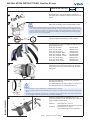
If the instrument is mounted flush (i. e., from the back
so that the instrument glass and the panel form one
plane), the front ring must be removed. Press the
instrument glass with both thumbs, while at the same
time pressing the front ring forward from the instrument with both index fingers. Note the use of a tool
in the adjacent figure.
8
1
2
Flush assembly.
9
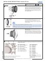
ø 75.4 mm
The recommended panel thickness is 1.5 to 3 mm.
The drill hole must have a diameter of 75.4 mm.
Ensure that the installation location is level and has
no sharp edges.
• Do not drill holes or ports in load-bearing or stabilizing stays or tie bars!
• Note the necessary clearance behind the drill hole or port at the installation location. Required mounting depth:
65 mm.
• Drill small ports; enlarge and complete them, if necessary using taper milling tools, saber saw, keyhole saw or
1.5...3 mm
file. Debur edges. Follow the safety instructions of the tool manufacturer.
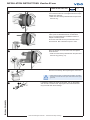
Place the flush mount seal A2C53215641 on the
instrument glass.
Put the instrument into the drill hole from the back.
Adjust the instrument so that the gauge is level and
fasten it to the stud bolts on the rear side of the panel,
using the flush mount fixing bracket A2C59510864.
10
11
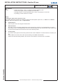
Depending on the configuration, insert the cable into the 8-pin and 14-pin
contact housing according to the following pin assignment. The contacts must
audibly lock into place.
1
7
14
8
4
8
TU00-0752-7407102
5
8-pin contact housing
Pin 1 - Term. 30 - battery12/24 V
Pin 2 - Term. 31 - ground
Pin 3 - signal ground
Pin 4 - Term. 15 - ignition plus
Pin 5 - sensor signal
Pin 6 - Term. 58 - lighting
Pin 7 - programming port Tx
Pin 8 - programming port Tx
1
Now insert the plug into the gauge. Note the inverse
polarity protection nose in the process.
14-pin contact housing
Pin 1 - NMEA0183-B
Pin 2 - NMEA0183-A
Pin 3 - unassigned
Pin 4 - unassigned
Pin 5 - unassigned
Pin 6 - unassigned
Pin 7 - unassigned
Pin 8 - unassigned
Pin 9 - unassigned
Pin 10 - unassigned
Pin 11 - Configuration key
Pin 12 - Mode key
Pin 13 - Alarm output (max 100 mA)*
Pin 14 - unassigned
* Optional, please contact your VDO
dealer about this
Technische Änderungen vorbehalten - Technical details subject to change