1
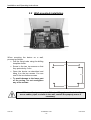
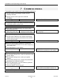
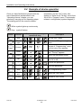
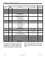
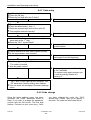
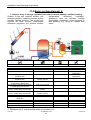
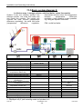
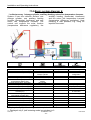
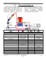
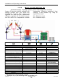
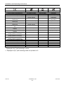
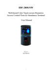
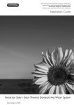
Installation and Operating Instructions
11.4 Basic system diagram 4:
1 collector array, 2 storage cylinders (hot water), thermal transfer, auxiliary heating
System 4 has one collector surface, two
(temperature
difference
regulation,
storage cylinders, a transfer function and an
timeframe) and the auxiliary heating
auxiliary heating function. The control unit
(thermostat, timeframe). Heat metering is
controls the solar function (temperature
also possible, e.g. using an impeller flow
difference regulation, the thermal transfer
meter.
Info
I
Current collector temperature (E1)
Minimum collector temperature (E1)
Maximum collector temperature (E1)
Program
I
Timeframe R2 start
Timeframe R2 stop
Timeframe R3 start
Current storage cylinder temperature
Timeframe R3 stop
at bottom (E2)
Minimum storage cylinder temperature Maximum temperature of
at bottom (E2)
storage cylinder
Maximum storage cylinder
Solar circuit Td start
temperature at bottom (E2)
Current thermal transfer storage temp.
Solar circuit Td stop
in middle (E3) for R2 and R3.
Minimum thermal transfer storage
Start temperature, auxiliary
temp. in middle (E3) for R2 and R3.
heating
Minimum thermal transfer storage
Max temp. of transfer
temp. in middle (E3) for R2 and R3.
storage cylinder
Current storage temp. at top (E4)
R3 Td start
Minimum storage cylinder temperature
R3 Td stop
at top (E4)
Maximum storage temp. at top (E4)
Set time
Flow rate ∗
Daily yield ∗
Total yield ∗
Manual operation
I
Pump A1 off/on
A2 off/on
A3 off/on
A4 off/on
Basic setting
I
Code entry
Reset/factory setting
Select basic
configuration
Maximum collector
temperature
Mode yield metering
Volume flow ∗
DFG/WMM ∗∗
Glycol type ∗
Glycol percentage ∗
Tolerance for solar yield
Code change
∗ Displayed only if yield metering mode is equivalent to 1 or 2.
∗∗ Displayed only if yield metering mode is equivalent to 2.
SDC 306
1316BED036-11B-E
- 35 -
Date 06/09