1
Light Commercial
INSTALLATION INSTRUCTIONS
High Static Blower Drive Kits
6 - 15 Ton Light Commercial Package System
GENERAL
These instructions are primarily intended to assist qualified individuals experienced in the proper installation of heating and/
or air conditioning appliances. Some local codes require licensed installation/service personnel for this type equipment and
their accessories. All installations must be in accordance with these instructions and with all applicable national and local
codes and standards. Please read all instructions thoroughly before installing the kit.
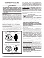
WARNING:
WARNING:
ELECTRICAL SHOCK, FIRE OR EXPLOSION
HAZARD
Failure to follow safety warnings exactly could result
in serious injury or property damage.
Improper installation or servicing could result
in dangerous operation, serious injury, death or
property damage.
• Before servicing, disconnect all electrical power
to the unit.
• When servicing controls, label all wires prior to
disconnecting. Reconnect wires correctly.
• Verify proper operation after servicing.
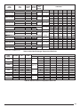
KIT #
Motor
918799
X
918800
Improper installation, service, adjustment, or
maintenance can cause fire, electrical shock, or
other conditions which may result in personal
injury or property damage. Unless otherwise noted
in these instructions, only factory authorized kits,
parts or accessories may be used when modifying
this equipment.
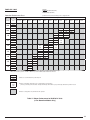
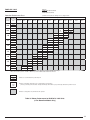
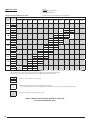
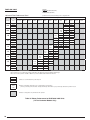
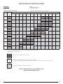
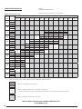
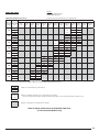
NOTETO INSTALLER: The blower drive kits listed in Table 1 are
applicable only to NORDYNE units equipped with NORDYNE
motors. The use of these kits with non-NORDYNE motors may
not produce the same values shown in the airflow tables or
other data provided.
920394
X
920395
X
920396
X
920558
X
920559
X
920606
X
X
X
X
X
X
Ext. Motor Overload
X
Overload Adapter
X
Motor Sheave
X
X
Blower Pulley
X
X
X
X
X
X
X
X
Drive Belt
X
X
X
X
X
X
X
X
Overload Wires
X
X
X
X
X
X
X
Parts Kit
X
X
X
X
X
X
X
X
920607
920608
920609
920613
920618
920560
920637
X
X
X
X
X
X
X
Ext. Motor Overload
X
X
X
X
X
Overload Adapter
X
X
X
X
X
X
X
X
X
X
KIT #
Motor
Motor Sheave
X
Blower Pulley
X
X
X
X
X
X
X
Drive Belt
X
X
X
X
X
X
X
Overload Wires
X
X
X
X
X
X
X
Parts Kit
X
X
X
X
X
X
X
Table 1. Blower Drive Kit Contents & Part Numbers
IMPORTANT SAFETY INFORMATION
INSTALLER: Please read all instructions before servicing this equipment. Pay attention to all safety warnings and any other special notes
highlighted in the manual. Safety markings are used frequently throughout this manual to designate a degree or level of seriousness and
should not be ignored. WARNING indicates a potentially hazardous situation that if not avoided, could result in personal injury or death.
CAUTION indicates a potentially hazardous situation that if not avoided, may result in minor or moderate injury or property damage.
TABLE OF CONTENTS
Kit Applications .................................................................3
Recommended Sizing of 3 Phase Supply Wires ...........10
Pre-Installation Information ..............................................4
Before You begin ..............................................................4
Pre-Installation Checklist ..................................................4
HSDK Installation Method ................................................4
Airflow Data for Medium Static Drives...........................11
Table 7. P6SP-072* Downflow Models (6T)....................11
Table 8. P6SP-072* Horizontal Models (6T) ...................12
Table 9. P6SP-090 Downflow Models (7.5T) ..................13
Table 10. P6SP-090 Horizontal Models (7.5T) ...............14
Table 11. R6GP-072*-100C Downflow Models (6T) .......15
Table 12. R6GP-072*-100C Horizontal Models (6T) ......16
Table 13. R6GP-072*-166C Downflow Models (6T) .......17
Table 14. R6GP-072*-166C Horizontal Models (6T) ......18
Table 15. R6GP-090*-200C Downflow Models (7.5T) ....19
Table 16. R6GP-090*-200C Horizontal Models (7.5T) ...20
External Motor Overloads .................................................5
Application ........................................................................5
Auxiliary Contacts.............................................................5
Trip Class .........................................................................5
Phase Failure Sensitivity ..................................................5
Setting the Overload Relay ..............................................5
STOP Function .................................................................5
Manual/Automatic Reset ..................................................5
TEST Function & Switch Position Indicator ......................5
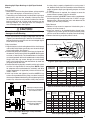
Motor Sheave / Pulley’s / Belt Installation &
Adjustment .........................................................................6
Motor Pulley .....................................................................6
Single Groove Adjustable Motor Sheaves with
Keyways or Barrel Flats ....................................................6
Mounting Split Taper Bushings in Split Taper
Bushed Pulleys.................................................................7
Pre-Installation ..............................................................7
Pulley Installation ..........................................................7
Pulley Removal .............................................................7
V-Belt Alignment & Tensioning .........................................8
Verifying the Installation ...................................................8
Line Voltage ......................................................................8
Grounding.........................................................................8
Unbalanced 3-Phase Supply Voltages .............................9
Blower Speed ...................................................................9
Measuring the Blower Speed ........................................9
Changing the Blower Speed .........................................9
External Motor Overload ..................................................9
2
Airflow Data for High Static Drives. ...............................21
Table 17. P6SP-090* Downflow Models (7.5T)...............21
Table 18. P6SP-090* Horizontal Models (7.5T) ..............22
Table 20. P6SP-120* & Q6SP-120* & Q5SN-120*
Downflow Models (10T) ..................................23
Table 20. P6SP-120* & Q6SP-120* & Q5SN-120*
Horizontal Models (10T) .................................24
Table 21. Q6SP-090* & Q5SN-090*
Downflow Models (7.5T) .................................25
Table 22. Q6SP-090* & Q5SN-090*
Horizontal Models (7.5T) ................................26
Table 23. R4GM & R6GN-150* Series (12.5T) ...............27
Table 24. R4GM & R6GN-180* Series (15T) ..................28
Table 25. R6GP-090* -200C Downflow Models (10T) ....29
Table 26. R6GP-090* -200C Horizontal Models (10T) ...30
Table 27. R6GP-120* -235C Downflow Models (10T) ....31
Table 28. R6GP-120* -235C Horizontal Models (10T) ...32
Temperature Rise Data....................................................33
Table 29. Gas Heat Exchanger Temp. Rise Data............33
Table 30. Electric Heater Kit Temperature Rise Data .....33
Installation / Performance Checklist ..............................36
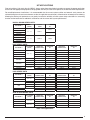
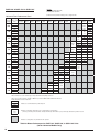
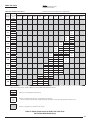
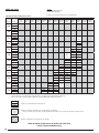
KIT APPLICATIONS
Prior to installing a high static drive kit (HSDK), always review these installation instructions to ensure the proper application
of the kit for the appropriate equipment to be upgraded and verify that the kit will operate at the desired airflow requirements.
For retrofit/replacement installations, it is recommended that the current systems airflow and external static pressure be
attained through on-site test measurements and/or the applicable manufacture’s airflow data be reviewed prior to ordering.
Knowing the existing unit performance can greatly increase the reliability of initial system setup calculations in accounting
for other airflow losses due to additional accessories and the current duct system performance.
R6GN & GR4GM SERIES UNITS
UNIT MODEL #
RANGE
(IN-WG)
BLOWER
CHART
1.1 - 1.9
PAGE 27
-150C-180C
HSD
KIT
918799
-150C-270C
-150D-180C
920637
-150D-270C
-180C-270C
-180C-315C
1.1 - 1.9
PAGE 28
918800
E.S.P. RANGE
(IN-WG)
DOWNFLOW
BLOWER CHART
DOWNFLOW
KIT
-180D-270C
-180D-315C
R6GP SERIES UNITS
UNIT MODEL #
HORIZONTAL
BLOWER CHART
HORIZONTAL
KIT
-072C-100C
PAGE 15
920609
PAGE 16
920609
-072C-166C
PAGE 17
920609
PAGE 18
920613
-072D-100C
PAGE 15
920560
PAGE 16
920560
-072D-166C
PAGE 17
920560
PAGE 18
920618
0.8 - 1.6
PAGE 19
920607
PAGE 20
920607
1.2 - 2.0
PAGE 29
920559
PAGE 29
920559
0.8 - 1.6
PAGE 19
920606
PAGE 20
920606
1.2 - 2.0
PAGE 29
920558
PAGE 29
920558
PAGE 31
920395
PAGE 32
920395
PAGE 31
920396
PAGE 32
920396
DOWNFLOW
BLOWER CHART
DOWNFLOW
KIT
HORIZONTAL
BLOWER CHART
HORIZONTAL
KIT
PAGE 11
920609
PAGE 12
920609
PAGE 11
920560
PAGE 12
920560
0.8 - 1.6
PAGE 13
920607
PAGE 14
920607
1.2 - 2.0
PAGE 21
920559
PAGE 22
920559
0.8 - 1.6
PAGE 13
920606
PAGE 14
920606
1.2 - 2.0
PAGE 21
920558
PAGE 22
920558
PAGE 23
920395
PAGE 24
920395
PAGE 23
920396
PAGE 24
920396
DOWNFLOW
BLOWER CHART
DOWNFLOW
KIT
HORIZONTAL
BLOWER CHART
HORIZONTAL
KIT
PAGE 25
920394
PAGE 26
920394
PAGE 25
920608
PAGE 26
920608
PAGE 23
920395
PAGE 24
920395
PAGE 23
920396
PAGE 24
920396
0.8 - 1.6
-090C-200C
-090D-200C
-120C-235C
1.1 - 2.0
-120D-235C
P6SP SERIES UNITS
UNIT MODEL #
-072C
-072D
-090C
-090D
-120C
-120D
E.S.P. RANGE
(IN-WG)
0.8 - 1.6
0.9 - 2.0
Q6SP & Q5SN SERIES UNITS
UNIT MODEL #
-090C
-090D
-120C
-120D
E.S.P. RANGE
(IN-WG)
1.1 - 2.0
0.9 - 2.0
Table 2. Kit Applications
3
PRE-INSTALLATION INFORMATION &
INSTALLATION METHOD
Before You Begin
It is recommended that prior to a kit selection for a retrofit
installation, the existing duct system be inspected for security
and possible improvements. The removal of flexible duct
sections or replacement of under sized ducts can significantly
improve a buildings air distribution system for increased unit
efficiency, correction of room stratification issues for personal
comfort and reduction of equipment noise levels transferred
through the ducts.
Some local codes require testing a buildings duct system for
external air infiltration and correcting any deficient structures.
Commercial duct systems should be designed for compliance
with the guidelines given in the ASHRAE Handbooks, ACCA
Manual Q, SMACNA manuals or as specified by any applicable
NFPA and local codes or ordinances that may apply. Improving
an existing duct system could be more cost effective then
increasing the units airflow when weighed against the increased
energy cost for the designed life of the equipment.
Always make sure all equipment installation instructions are
on-hand and reviewed prior to the commencement of any work
for the unit and all field installed accessories.This accessory kit
should be installed prior to the installation of any economizers,
air-dampers, or other kits that require the blower operation
for final setup. On roof top installations, these kits could be
partially installed at ground level prior to the final unit placement
in order to reduce the number of crane operations required.
Pre-Installation Checklist
• Verify the HSDK matches the unit application and building
voltage requirements in Table 2 (page 3).
• Inspect the kit and verify the contents to Table 1 (page 1).
• Inspect the duct system for security, air leakage or infiltration,
and that it is properly constructed for the airflow/pressure
requirements of the HSDK.
• Review all equipment and accessory installation instructions
prior to beginning the installation.
• Verify that the unit supply wiring, unit disconnect & overcurrent protection is sized properly for the addition of the
HSDK and any other accessory kits that will utilize the same
electrical circuit. See Figure 9 (page 10) for recommended
procedure on how to determine the proper 3 phase wire size.
MOTOR
RATED
PART
POLES
HP
NUMBER
621819
621820
3
3
4
4
622006
5
4
622026
2
4
622074
3
4
622254
622305
2
1.5
4
4
NOTES:
VOLTAGE
200-230
460
208-230/460
190 / 380
208-230/460
208-230/460
190 / 380
208-230/460
208-230/460
FLA = Full Load Amps
SF = Service Factor
† Approximate Efficiency
HZ
60
60
60
50
60
60
50
60
60
Ø
3
3
3
3
3
3
3
3
3
HSDK Installation Method
1. Set the thermostat and unit disconnect(s) to the OFF position.
Verify that the unit has been isolated from all electrical
power sources. For HSDK’s that do not require a motor
replacement, go to step 6.
2. Open/remove the access panels for the units control
panel, blower compartment and field wiring compartments.
NOTE: Never lift or hoist a unit without the access panels
installed or closed and securely attached with all of the
screws supplied from the factory. Refer to the unit installation
instructions for additional details if necessary.
3. Locate the blower motor and trace the motor wires back to
the blower motor contactor or external motor relay. Carefully
cut any zip-ties to free the motor wires from the unit or wiring
harness.
4. Disconnect the motor wires from the overload relay or
contactor T1, T2 & T3 terminals or box lugs.
5. Remove the factory motor & lead assembly from the motor
mounting plate and install the HSDK motor & lead assembly
in the unit. See Figure 1 (page 5) for overload relay mounting
locations.
6. Install the motor overload relay (if required) as described
on page 5. Re-route the blower motor wires to the overload
or blower contactor and secure with the supplied zip-ties.
• Refer to Table 1 to determine the HSDK motor part number
and then Table 3 to determine the service factor amps (SFA)
for the HSDK motor at the correct unit supply voltage. Set
the external overload relay to the motor SFA for that voltage.
NOTE: Replacement overload relay part numbers can be
found using the data in Tables 3 & 4.
7. Verify the proper operation of the motor sheave. Refer to the
blower chart called out for the application in Table 1 and set
the sheave to the proper set-point. Install the HSDK blower
pulley and belt and reference the instructions on pages 6 - 8.
Tighten the belt and secure the assembly.
8. Verify that all electrical connections have been made and
wiring properly secured. Complete the instructions on
verifying the electrical phase balance and blower rotation
direction (pages 8 - 9).
9. After the completion of any other unit or accessory installation
requirements, close or re-install the blower compartment
access panel and restore the electrical power to the unit.
Verify that the unit is delivering the proper airflow as described
on pages 8 - 9.
10. Replace all other access panels and refer to the unit
installation instructions to complete the installation and
place the unit into normal service.
RATED
RPM
NEMA
NOM.
EFF.
NEMA
FRAME
SIZE
1725
1725
1760
1445
1755
1765
1455
1725
1755
81% †
81% †
87.5%
84%
85.5%
86.5%
84%
84% †
86.5%
145T
145T
184T
145T
182T
145T
145T
MOTOR AMPERAGE
FLA
SF
SFA
9.10 - 8.90
4.4
14.0 - 13.4 / 6.7
15.9 / 7.9
5.8 - 5.5 / 2.8
8.8 - 8.6 / 4.4
9.8 / 4.9
6.2 - 5.8 / 2.9
4.4 - 4.2 / 2.1
1.15
1.15
1.15
1.00
1.15
1.15
1.00
1.15
1.15
10.2 - 9.70
4.8
15.0 - 15.0 / 7.5
15.9 / 7.9
6.6 - 6.1 / 3.1
10.1 - 9.9 / 5.0
9.8 / 4.9
7.0 - 6.6 / 3.3
5.0 - 4.6 / 2.3
SFA = Service Factor Amps
Nom. Eff. = Nominal Efficiency
Table 3. High Static Drive Motor Data
4
REQUIRED
EXTERNAL
PROTECTOR
- N/A - N/A YES
YES
YES
- N/A YES
RANGE OF
PROTECTION
(AMPS)
RELAY PART
NUMBER
REQUIRED
MOUNTING PLATE
1.4 - 2.0
1.8 - 2.5
624728
624729
622032
622032
2.8 - 4.0
622034
622032
3.5 - 5.0
622075
622032
5.5 - 8.0
7.0 - 10.0
622031
622077
622032
622032
11.0 - 16.0
622082
622083
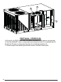
6-1
0 TO
NEL
Over
Mou load Rela
nting
Loca y
N PA
tion
CKA
GED
A
(6 TO IR CON
DIT
N MO
DEL ONER C
SHO
WN) ONTROL
6-1
0 TO
Table 4. Overload Relay Data
(3Ø Motor External Protectors)
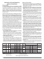
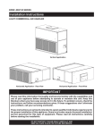
EXTERNAL MOTOR OVERLOADS
Application
Siemens 3RU11 overload relays provide overload protection
for three-phase inductive motors with rated currents of up to
100A (75HP, AC-3, 480V). Most NORDYNE motors do not
require an external motor protector. Refer to Table 3 (page 4)
to determine which kits require protectors.
N PA
CKA
GED
(6 TO GAS / E
LE
N MO
DEL CTRIC C
O
SHO
WN) NTROL
PA
PAN
E
L
Over
Mou load Rela
nting
Loca y
tion
12.5
- 15
TON
C
ONT
ROL
PAN
E
L
Auxiliary Contacts
The overload relays are equipped with a NC contact for deenergizing the contactor and a NO contact for signalling an
overload trip. The breaking capacity of the switching contacts
is very high so that the contactor coils can be switched directly.
Trip Class
The 3RU11 overload relays are designed in accordance with
trip class 10 (e.g. The protector will trip in less than 10 seconds
at 6 times the trip current setting (FLA).
Phase Failure Sensitivity
A phase failure sensitivity function is integrated in to the relay
in order to provide increased protection in the event of a phase
failure, i.e. faster tripping in the event of a single-phase condition.
Over
Mou load Rela
nting
Loca y
tion
Figure 1. Overload Relay Mounting Locations
Mounting
Hole
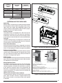
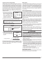
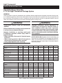
Setting the Overload Relay
The current setting dial can be accessed once the transparent,
sealable cover has been opened. The overload relay must be
set at the rated Service Factor Amps (SFA) of the motor for
the proper unit voltage. See Figure 2.
1
5
2
6
3
STOP Function
Pressing the red STOP button on the overload relay momentarily
opens the NC trip contact. No other contacts and/or functions
are affected by this STOP button.
Manual/Automatic Reset
The RESET button/mechanism features trip-free operation.
This means that the overload relay will trip on an overload
condition regardless of whether the reset button is pushed in
or not. Manual or automatic reset can be selected with the
blue button. The appropriate setting is selected by pressing
and turning the button. This setting can then be locked by the
sliding transparent cover.
TEST Function & Switch Position Indicator
The switch position indicator also incorporates a test function
which, when activated, simulates a tripped overload relay.
Both auxiliary contacts are actuated and the switch position
is indicated.
Mounting
Hole
7
8
4
MOUNTING PLATE
9
3RU111 OVERLOAD RELAY
1. Equipment identifying marker
2. Manual/Automatic RESET selector switch
3. STOP button
4. Complete Catalog # on front of device
5. Switch position indicator and TEST function
6. Transparent cover, sealable (secures the current setting screw, TEST function
and manual/automatic RESET position)
7. Current setting dial
8. Terminal for contactor coil (when mounted on contactor)
9. Terminal for contactor aux. contacts (when mounted on contactor)
Figure 2. Overload Relay & Mounting Plate
5
MOTOR SHEAVE / PULLEYS / BELT
INSTALLATION & ADJUSTMENT
WARNING:
Never perform maintenance on energized or rotating
equipment. Always disconnect electrical power and
allow all rotating equipment to stop before servicing the
unit. Failure to do so may result in personal injury, loss
of limb, or death from electrical shock or entanglement
in moving parts.
Motor Pulley
The motor pulley or sheave is a variable pitch style pulley
which allows blower speed adjustments over a wide range
of applications. While the terms pulley and sheave can be
interchanged, in this document, the adjustable motor pulley is
referred to as a sheave or adjustable sheave, and the blower
sheave is referred to as the pulley or blower pulley. Refer to
the installation instructions supplied with the unit or refer to
Tables 7 - 32 (pages 11 - 32) in this manual for proper airflow
settings for each individual unit & kit. Do not adjust a motor
pulley to a setting that is not shown on the table for that unit’s
application for that specific kit. Refer to Table 2 (page 3) to
determine the proper blower chart for each application.
On 6-10T Packaged Models: The blower pulley in the kit is a
simple AK or BK style pulley, sized for the application and the
unit’s blower shaft size. To remove or install, simply loosen the
set screw and slide the pulley from the blower shaft. Make
sure the shaft key is retained for installation of the new pulley.
ADUSTABLE SHEAVE WITH KEYWAYS
Motor Shaft
Keyway
Adjustable
Sheave Keyway
Stationary
Sheave Face
Motor Shaft
Set Screw
Key
y
Ke
Adjustable Sheave
Keyway Set Screw
Adjustable Sheave Face
ADUSTABLE SHEAVE WITH BARREL FLATS
Motor Shaft
Keyway
Barrel
Flat
Stationary Sheave Face
Motor Shaft
Set Screw
Barrel
Flat
FLAT
Adjustable Sheave
Set Screw Adjustable Sheave Face
Figure 3. Adjustable Sheaves with Keyways or
Barrel Flats
6
During installation, set the variable sheave position first,
then adjust the blower pulley on the blower shaft to align the
centers of the pulley and sheave. The set screw should always
be above the pulley shaft key. Do not tighten the set screw
directly onto the blower shaft.
On 12.5-15T Models: The blower pulleys are referred to as
the split-taper style. This style of pulley positively locks the
blower pulley to the shaft for higher horsepower applications.
Refer to page 7 for instructions on how to install and remove
these pulleys.
Single Groove Adjustable Motor Sheaves with Keyways
or Barrel Flats
IMPORTANT NOTES:
• Do not force belts over grooves! A belt tension checker
should be used to set tension.
• Future adjustments should be made by loosening the
belt tension and increasing or decreasing the pitch
diameter of the sheave by half or full turns as required.
Readjust belt tension before starting drive.
• Make sure the key is in place and that all set screws
are torqued properly before starting drive. Check set
screws and belt tension after 24 hours service.
• Sheaves can only be adjusted in 1/2 turn increments.
Never attempt to tighten a set screw on to the threaded
portion of the sheave barrel.
1. Make sure the shaft, sheave bore and keyway are free of
burrs, paint, etc.
2. Mount all sheaves on the motor or driving shaft with the
end containing the motor shaft set screw toward the motor.
NOTE: For single groove sheaves with keyways (Figure 3),
always make sure the motor sheave is fully installed onto
the motor shaft.
3. Fit shaft key between sheave & shaft and lock set screw
in place. Wrench torque to 110 in-lb min. - 130 in-lb max.
NOTE: Make sure both driving and driven sheaves are
in alignment and that shafts are parallel. Total axial and
parallel misalignment must not exceed 1/4°. See page 8
for information about V-belt alignment and tensioning.
4. Sheaves with Keyways: Loosen keyway set screw in
adjustable sheave and pull out the external key. NOTE: The
end of the key projects a small amount to provide a gripping
surface for removing. See Figure 3.
Sheaves with Barrel Flats: Loosen sheave set screw in
adjustable sheave until adjustable flange rotates freely.
5. Adjust sheave pitch diameter for desired speed by opening
rotating parts by half or full turn increments from closed
position. IMPORTANT: Do not set the motor sheave to
points not shown on the blower table for your application.
6. Sheaves with Barrel Flats: Tighten sheave set screw to 110
to 130 in-lb. with set screw located over the center of the
barrel flat. DO NOT TIGHTEN THE SET SCREW ON THE
THREADED PART OF THE SHEAVE.
Sheaves with Keyways: Replace key and tighten the set
screw to 110 to 130 in-lb.
7. Install blower pulley and align the pulleys.
8. Install belts on the sheaves and adjust belt tension.
Mounting Split Taper Bushings in Split Taper Bushed
Pulleys
Pre- Installation
• Make sure the shaft, bushing barrel & bore, split taper pulley
bore, keys and keyways are free of burrs, paint, etc.
• The bushing may first be loosely installed into the split taper
bored pulley, and then the assembly slid onto the shaft.
For heavier pulley’s, it may be easier to either first slide the
bushing onto the shaft and then slide the pulley onto the
bushing; however, if the bushing barrel has collapsed, it
must be wedged open. See Figure 4.
CAUTION:
Excessive wedging forces in bushing saw slot may
damage or break bushing.
• It may be necessary to slightly wedge open the saw slot
(Figure 5) on some bushings in order to start the bore and
position the bushing onto the shaft. A narrow edged regular
screw driver may be used.
Pulley Installation
1. Align the keyway in the bushing bore with the shaft keyway
and install the key. Make sure the key runs the entire length
of the bushing bore. See Figure 5.
2. Position the pulley so the keyway in the bore is aligned with
the external (barrel) key in the bushing. NOTE: Bushings do
not have an external key. The threaded holes in the pulley
must be aligned with the non-threaded holes in the bushing
flange. Insert the cap screws through the non-threaded
holes in the bushing flange and thread them by hand into
the pulley three or four turns.
3. Position the bushing & pulley assembly axially on the shaft
such that it is aligned with its running mate. NOTE: Check
for adequate clearance between the assembly and other
nearby components (if applicable). Various shaft sizes are
listed in Table 5.
4. Install cap screws and tighten by hand first. NOTE: If cap
screws were provided with the pulley, use them instead of
the ones provided with the bushing. Since tightening the cap
screws may affect the axial position of the pulley, confirm
Split Taper Pulley & Bushing
Components Assembled and
then Installed on Shaft
that the pulley is properly aligned with its running mate. If
not, determine how much the assembly must be moved into
proper alignment. Split taper tightening torques are listed
in Table 6.
5. If axial adjustment is required, first attempt to move the
motor sheave to properly align the drive belt.
6. Check installation gap. NOTE: There must be a gap between
the bushing flange and the pulley face. If there is no gap
between them, disassemble the parts and determine the
reason(s) for the faulty assembly.
Pulley Removal
1. Remove all cap screws in sequence. If the bushing has a
keyway set screw, loosen it.
2. Insert cap screws in all threaded bushing flange holes.
Tighten the cap screws against the (hub) face of the pulley
until the screw force releases the pulley from the bushing.
3. Remove the bushing and pulley from the shaft.
Split Taper Bushing
Keyway
Split Taper Pulley
Figure 5. Split Taper Bushing & Pulley Assembly
Above
Through
LOWER
SHAFT
SIZE LIMIT
(IN)
–
1 1/2
2 1/2
4
6
8
9
1 1/2
2 1/2
4
6
8
9
—
-0.003
-0.004
-0.005
-0.006
-0.007
-0.008
-0.009
SHAFT SIZE
RANGE (IN)
SAE Grade 5
Cap Screw
No.
Figure 4. Split Taper Bushing & Pulley Assembly
Options
LOWER
SHAFT
SIZE LIMIT
(MM)
SHAFT SIZE
RANGE (IN)
Above Through
—
38.1
63.5
101.6
152.4
203.2
228.6
38.1
63.5
101.6
152.4
203.2
228.6
—
-0.076
-0.102
-0.127
-0.152
-0.178
-0.203
-0.229
Table 5. Shaft Size Limits for Split Taper Bushings
Bushing
Split Taper Pulley & Bushing
Components Installed on
Shaft Individually
Saw Slot
Cap Screws & Washers (3)
Size
Cap Screw Torque
Set
Screw
Size
(in-Lbs) (Ft-Lbs) (N-M)
Set Screw Torque
(in-Lbs) (Ft-Lbs) (N-M)
G;H
2
1/4-20NC
95
8
10.7
-
-
-
-
P;B
3
5/16-18NC
192
16
21.7
-
-
-
-
Q
3
3/8-16NC
348
29
39.3 5/16-18NC
165*
13.8* 18.6*
R
3
3/8-16NC
348
29
39.3 5/16-18NC
165
13.8
18.6
S
3
3/8-16NC
840
140
189.8 3/8-16NC
290
24.2
32.8
U
3
5/8-11NC
1680
140
189.8 3/8-16NC
290
24.2
32.8
W
4
3/4-10NC
3000
250
339.0 1/2-13NC*
620*
51.7* 70.1*
YO
4
1-8NC
7200
600
813.5 1/2-13NC*
620*
51.7* 70.1*
Table 6. Split Taper Tightening Torques
7
V-Belt Alignment & Tensioning
IMPORTANT NOTE: Belt alignment is extremely critical for
proper operation and life expectancy of belts and motor
bearings. If not equipped with proper alignment tools,
prior to removal of blower and motor pulley, measure
center of each pulley to a reference point for replacement
of new pulleys.
After installing the blower pulley onto the blower shaft, use
an in-groove belt alignment tool to verify the parallel offset of
the sheave and pulley. If a laser alignment tool is unavailable,
place a straight edge, piano wire, or string in the center of
the adjustable sheave and pulley V-notch to adjust parallel
offset alignments.
NOTE: The straight edge, piano wire or string should be close
to the center of the groove and contact each sheave in two
places. The objective is to have the center lines of the two
sheaves in line. Belt drives should be aligned as perfect as
possible to maximize drive life. See Figure 6.
Calculate or measure the belt span length as shown in Figures
7 & 8. Calculate the required deflection by multiplying this
number by 1/64. For example, if the belt span is 32 inches,
32 x 1/64 = 1/2 inch deflection. NOTE: Excessively high or
low tensions will affect belt life. Check belt tensions again
after 24 hours of operation. Keep extra belts stored in a cool,
dark, dry place.
Figure 6. V-Belt Alignment
On 12.5-15T Models: The belt tension is controlled utilizing the
adjustable motor mounting plate. To release the belt tension,
first loosen the 4 motor mounting nuts that attach the motor to
the mounting plate approximately ½-1 turn and then use the
adjusting bolt to release the belt tension. To tighten, complete
the steps in the reverse order.
On 6-10T Packaged Models: The belt tension is controlled
utilizing the belt-tensioning bars on the top and bottom of the
motor mounting plate. To release the belts tension, first loosen
the bolts in the adjustable slot of each tensioning bar first,
followed by the second bolt in each tensioning bar. Swing the
motor & motor plate assembly towards the blower. To tighten,
use a pry-bar to apply pressure to the top of the motor plate
and tighten the top belt tensioning bar. Verify the motor is
plumb and that the shaft is vertically aligned by adjusting the
bottom of the motor plate, then tighten the bottom tensioning
bar bolts. When complete, always verify the belt tension and
alignment, do not over-tighten.
VERIFYING THE INSTALLATION
Line Voltage
Maximum circuit ampacity and maximum overcurrent protection
ratings may vary. See the unit rating plate for proper electrical
ratings. NOTE: Older equipment may not include a rating plate
that shows the HSDK maximum overcurrent protection and
other electrical data for the kit. Always verify this information
with the installation instructions included with the unit. If these
are not available then refer to Table 3 (page 4).
• Verify that the power supply for the unit is in accordance with
the units wiring diagram and rating plate. Use only copper
wire for the line voltage supply to this unit. Use proper code
agency listed conduit and connector for connecting the
supply wires.
• Verify all electrical connections are in accordance with all
applicable codes and ordinances. Any other wiring methods
must be acceptable to authority having jurisdiction. See
Figure 9 (page 10) for recommended wire size.
• Verify overcurrent protection is provided at the branch circuit
distribution panel and sized as shown on the unit rating label
and according to the National Electric Code and applicable
local codes.
Grounding
Center Distance
Figure 7. Pulley Alignment
Span Length, t
Force
Deflection (def)
Figure 8. Tensioning V-Belts
8
WARNING:
The unit cabinet must have an uninterrupted or
unbroken electrical ground to minimize personal
injury if an electrical fault should occur. Do not use
gas piping as an electrical ground!
This unit must be electrically grounded in accordance with
local codes or, in the absence of local codes, with the National
Electrical Code (ANSI/NFPA 70) or the CSA C22.1 Electrical
Code.
Unbalanced 3-Phase Supply Voltage
Voltage unbalance occurs when the voltages of all phases of
a 3-phase power supply are no longer equal. This unbalance
reduces motor efficiency and performance. Some underlying
causes of voltage unbalance may include: Lack of symmetry in
transmission lines, large single-phase loads, and unbalanced
or overloaded transformers. A motor should never be operated
with a phase imbalance (in supply) that is greater than 2%.
Perform the following steps to determine the percentage of
voltage imbalance:
1. Measure the line voltages of
your 3-phase power supply
where it enters the building
and at a location that will
only be dedicated to the unit
installation. (at the units circuit
protection or disconnect).
Example:
AB = 451V
BC = 460V
AC = 453V
2. Determine the average voltage in the power supply.
In this example, the measured line voltages were 451,
460, and 453. The average would be 454 volts (451 +
460 + 453 = 1,364 / 3 = 454).
3. Determine the maximum deviation:
Example:
From the values given in step 1, the BC voltage (460V)
is the greatest difference in value from the average:
460 - 454 = 6
Highest Value
454 - 451 = 3
454 - 453 = 1
4. Determine percent of voltage
imbalance by using the results
from steps 2 & 3 in the following
equation.
Blower Speed
The blower speed for these accessory kits is not set at the
factory and must be verified for each installation. For optimum
system performance and comfort, refer to blower performance
data (Tables 7 - 28, pages 11 - 32) for proper operating range.
Always verify drive belt are secure and tensioned properly.
Also inspect variable pitch sheaves for proper tightness of
the set screws.
Measuring the Blower Speed
For units equipped with either an electric heat kit or gas heat
exchanger, the best method to determine the delivered CFM
is through a temperature rise measurement. Using quality
instruments, insert a temperature probe into the units supply
and return ducts. Provide the unit a call for the maximum heat
capability and either calculate the airflow for the measured
temperature rise or reference Tables 29 or 30 (page 33) to
estimate the CFM.
NOTE: For high static situations, never operate the blower
with the access panels removed for any length of time as
the blower motor may over-amp and trip the internal/external
protection. If it is desired to verify the blower RPM, always use
a remote indicator with the access panels closed.
To verify the blower rotation, the contactor can be manually
actuated for a brief period to “bump” the motor or the G terminal
can be briefly energized from R.
If necessary adjust the motor sheave to optimize the air
delivery. Always verify the motor amp draw at the contactor
to ensure it is less than the SFA for the unit/motor voltages
at the selected sheave setting
CAUTION:
Example:
6
100 x
= 1.32%
To avoid personal injury or property damage, make
certain that the motor leads do not make contact
with any uninsulated metal components of the unit.
454
% Voltage Imbalance = 100 x
max voltage deviation
from average voltage
average voltage
The amount of phase imbalance (1.32%) is satisfactory since
the amount is lower than the maximum allowable 2%. Please
contact your local electric utility company if your voltage
imbalance is more than 2%.
Changing the blower speed:
1. Disconnect all electrical power to the unit and remove the
blower access panel.
2. Loosen the motor tension bars to allow removal of the blower
belt from the motor sheave.
3. Loosen top set screw on motor sheave and turn clockwise
to close (increases blower speed), or counterclockwise to
open (decreases blower speed). NOTE: Make sure the center
of the sheave and pulley are properly aligned. Adjust the
sheave and pulley’s position on the motor or blower shaft
if necessary.
4. Replace belt on pulleys and position motor mounting plate
to correct position for proper belt tension.
5. Tighten tension bar bolts or adjustable motor base.
External Motor Overload
If installed, Verify that the overload is properly set for the motor
SFA and that it will trip when manually tested.
9
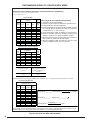
RECOMMENDED SIZING OF 3 PHASE SUPPLY WIRES
EXCERPTS FROM NEC 2005 HANDBOOK - BASED ON NFPA 70
Partial Table 310.16 Allowable Ampacities of Insulated Conductors (0-2000 Volts)
- Not more then 3 current carrying conductors in cable or raceway
- Based on Ambient Temp of 30˚C
Copper Wire Only
Size
Temperature Rating of
Conductor
Size
AWG or
kcmil
60˚C
75˚C
90˚C
AWG or
kcmil
14
12
10
8
6
20
25
30
40
55
20
25
35
50
65
25
30
40
55
75
14
12
10
8
6
4
70
85
95
4
3
2
1
85
95
110
100
115
130
110
130
150
3
2
1
1/0
2/0
3/0
125
145
165
150
175
200
170
195
225
1/0
2/0
3/0
How to Estimate Unit Supply Wire Requirements:
1.) Determine Nominal Input Voltage
2) Estimate Length of Wire from Breaker to Unit Disconnect
3) Find Unit MCA for desired configuration
4) Using the minimum wire size based on the unit MCA, calculate
the % Voltage Drop to determine the initial wire gauge. The
%VD should be 3% or less at the unit
5) Verify Unit Voltage is within the Appliances min/max limits
6) Verify that the Wire ampacity (corrected for temperature &
number of conductors) is above the Appliances MCA
7) Based on final wire gauge selection, determine conduit size.
Refer to NEC for details and allowable fill rate
8) Based on Appliance MOP and final wire selection, make
selection of Appliance branch circuit protection
Amb. Temperature Correction Factors
Temperature Rating
of Conductor
Amb.
Temp
(˚C)
60˚C
75˚C
90˚C
Amb.
Temp
(˚F)
21-25
26-30
31-35
36-40
41-45
46-50
51-55
1.08
1.00
0.91
0.82
0.71
0.58
0.41
1.05
1.00
0.94
0.88
0.82
0.75
0.67
1.04
1.00
0.96
0.91
0.87
0.82
0.76
70-77
78-86
87-95
96-104
105-113
114-122
123-131
Amount to adjust values in
Table 310.16 after correction
for Ambient Temperature (if
necessary)
# of Current-Carrying
Conductors
4 to 6
7 to 9
80%
70%
Partial Table 9 Effective Impedance for 600V Cables, 3Ø, 60 Hz, 75˚C - 3 single current-carrying conductors in conduit
Uncoated Copper Wire Only
Effective Impedance (Z) at 0.85 PF
to Neutral / 1000 ft
AWG or
kcmil
PVC
Conduit
Aluminum
Conduit
Steel
Conduit
14
12
10
8
6
4
3
2
1
1/0
2/0
3/0
2.7
1.7
1.1
0.69
0.44
0.29
0.23
0.19
0.16
0.13
0.11
0.088
2.7
1.7
1.1
0.69
0.45
0.29
0.24
0.19
0.16
0.13
0.11
0.092
2.7
1.7
1.1
0.70
0.45
0.30
0.24
0.20
0.16
0.13
0.11
0.094
VoltageDrop Lineto Neutraul Table9Value
CircuitLength
UnitMCA
1000 ft
VoltageDrop Lineto Line VoltageDrop Lineto Neutraul 3
%VoltageDrop
VoltageDrop Lineto Line
100
NomLineVoltage
The above tables and recommended procedures are provided for reference only. For complete details refer to the current version of
the National Electric Code, the applicable local codes & ordinances, or consult a qualified professional.
Figure 9. Excerpts from NEC 2005 Handbook
10
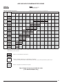
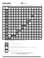
AIRFLOW DATA FOR MEDIUM STATIC DRIVES
P6SP-072*
MSD kits:
920609 (208-230V, 3Ø, 60 Hz)
920560 (460V, 3Ø, 60 Hz)
Downflow Performance Chart
‡ Indicates Factory Sheave Setting for Pre-configured Units
External Operating @
Unit Static 230 or 460
(in-Wg)
Volts
Adjustable Motor Sheave Setting
3.0 Turns
Open
3.5 Turns
Open
4.0 Turns
Open
4.5 Turns
Open
5.0 Turns
Open
CFM
2598
2437
2275
2097
1919
RPM
1039
1014
988
960
931
kW
1.23
1.10
0.97
0.87
0.77
2059
Fully
Closed
1/2 Turn
Open
1 Turn
Open
1.5 Turns
Open ‡
2.0 Turns
Open
2.5 Turns
Open
5.5 Turns
Open
6.0 Turns
Open
CFM
0.8
RPM
kW
0.9
1.0
1.1
1.2
1.3
1.4
1.5
1.6
CFM
2595
2405
2232
RPM
1066
1040
1016
991
kW
1.29
1.13
1.01
0.89
CFM
2770
2558
2392
2225
RPM
1123
1098
1071
1044
kW
1.55
1.36
1.20
1.04
CFM
2563
2401
2222
2043
RPM
1127
1102
1076
1049
kW
1.41
1.25
1.13
1.00
CFM
2557
2402
2246
RPM
1155
1129
1103
kW
1.47
1.33
1.19
CFM
2357
2182
2006
RPM
1157
1131
1105
kW
1.40
1.25
1.09
CFM
2455
2267
RPM
1185
1160
kW
1.45
1.35
CFM
2241
RPM
1189
kW
1.40
Values includes losses for: Unit Casing, 2” Disposable Filters & Dry Evaporator Coil
Values shown reflect operation at 230V or 460V. For operation at 208V, deduct 0.025 from unit static.
Deduct 250 Cfm for electric heater kits
3862
1159
Indicates a recommended unit operational point
3.03
3493
1017
Indicates an allowable setting that is not recommended for unit operation†
† These operational points should be carefully examined by the installer for proper unit setup and heater operation if used.
2.07
Indicates a setting that is not permitted for unit operation
Table 7. Blower Performance for P6SP-072* Units
(6 Ton Downflow Models Only)
11
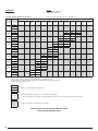
P6SP-072*
MSD kits:
920609 (208-230V, 3Ø, 60 Hz)
920560 (460V, 3Ø, 60 Hz)
Horizontal Flow Performance Chart*
‡ Indicates Factory Sheave Setting for Pre-configured Units
External Operating @
Unit Static 230 or 460
(in-Wg)
Volts
Adjustable Motor Sheave Setting
4.0 Turns
Open
4.5 Turns
Open
5.0 Turns
Open
CFM
2716
2500
2284
RPM
985
956
926
kW
1.17
1.05
0.93
2250
Fully
Closed
1/2 Turn
Open
1 Turn
Open
1.5 Turns
Open ‡
2.0 Turns
Open
2.5 Turns
Open
3.0 Turns
Open
3.5 Turns
Open
5.5 Turns
Open
CFM
0.8
RPM
kW
0.9
1.0
1.1
1.2
1.3
1.4
1.5
1.6
CFM
2677
2491
RPM
1012
987
959
kW
1.23
1.09
0.94
2255
CFM
2682
2469
RPM
1039
1015
990
kW
1.29
1.13
0.98
CFM
2663
2452
RPM
1067
1041
kW
1.35
1.18
CFM
2710
2465
2219
RPM
1096
1071
1046
kW
1.45
1.26
1.07
CFM
2675
2492
RPM
1126
1100
kW
1.47
1.33
CFM
2487
2195
RPM
1133
1109
kW
1.37
1.17
CFM
2558
2208
RPM
1159
1137
kW
1.48
1.20
*Requires horizontal conversion kit. Please refer to unit TSL for kit number.
Values includes losses for: Unit Casing, 2” Disposable Filters & Dry Evaporator Coil
Values shown reflect operation at 230V or 460V. For operation at 208V, deduct 0.025 from unit static.
Deduct 250 Cfm for electric heater kits
3862
1159
3.03
3493
1017
Indicates a recommended unit operational point
Indicates an allowable setting that is not recommended for unit operation†
† These operational points should be carefully examined by the installer for proper unit setup and heater operation if used.
2.07
Indicates a setting that is not permitted for unit operation
Table 8. Blower Performance for P6SP-072* Units
(6 Ton Horizontal Models Only)
12
6.0 Turns
Open
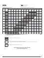
P6SP-090*
MSD kits:
920607 (208-230V, 3Ø, 60 Hz)
920606 (460V, 3Ø, 60 Hz)
Downflow Performance Chart
‡ Indicates Factory Sheave Setting for Pre-configured Units
External Operating @
Unit Static 230 or 460
(in-Wg)
Volts
0.8
0.9
1.0
1.1
1.2
1.3
1.4
1.5
1.6
Adjustable Motor Sheave Setting
Fully
Closed
1/2 Turn
Open
1 Turn
Open
1.5 Turns
Open ‡
2.0 Turns
Open
2.5 Turns
Open
3.0 Turns
Open
3.5 Turns
Open
4.0 Turns
Open
4.5 Turns
Open
5.0 Turns
Open
CFM
3415
3252
3042
2831
RPM
1119
1088
1059
1030
kW
1.92
1.73
1.62
1.50
CFM
3442
3247
3052
2834
2615
RPM
1150
1121
1092
1063
1033
kW
2.03
1.82
1.62
1.53
1.43
CFM
3447
3256
3072
2887
2658
2428
RPM
1181
1153
1124
1095
1065
1035
kW
2.11
1.85
1.66
1.47
1.39
1.31
CFM
3286
3077
2849
2621
RPM
1185
1157
1127
1097
kW
2.00
1.75
1.57
1.39
CFM
3326
3074
2822
2598
RPM
1215
1189
1162
1133
kW
2.20
1.92
1.64
1.42
CFM
3320
3064
2856
2647
RPM
1248
1221
1192
1163
kW
2.22
1.92
1.72
1.51
CFM
3365
3126
2887
2643
RPM
1277
1251
1224
1197
kW
2.32
2.09
1.86
1.57
CFM
3127
2911
2695
RPM
1283
1255
1227
kW
2.15
1.94
1.73
CFM
3323
3151
2978
2751
RPM
1340
1313
1286
1259
kW
2.54
2.30
2.05
1.80
5.5 Turns
Open
6.0 Turns
Open
Values includes losses for: Unit Casing, 2” Disposable Filters & Dry Evaporator Coil
Values shown reflect operation at 230V or 460V. For operation at 208V, deduct 0.025 from unit static.
Deduct 250 Cfm for electric heater kits
3862
1159
Indicates a recommended unit operational point
3.03
3493
1017
Indicates an allowable setting that is not recommended for unit operation†
† These operational points should be carefully examined by the installer for proper unit setup and heater operation if used.
2.07
Indicates a setting that is not permitted for unit operation
Table 9. Blower Performance for P6SP-090* Units
(7.5 Ton Downflow Models Only)
13
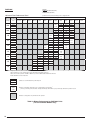
P6SP-090*
MSD kits:
920607 (208-230V, 3Ø, 60 Hz)
920606 (460V, 3Ø, 60 Hz)
Horizontal Flow Performance Chart*
‡ Indicates Factory Sheave Setting for Pre-configured Units
External Operating @
Unit Static 230 or 460
(in-Wg)
Volts
0.8
0.9
1.0
1.1
1.2
1.3
1.4
1.5
1.6
Adjustable Motor Sheave Setting
Fully
Closed
1/2 Turn
Open
1 Turn
Open
1.5 Turns
Open ‡
2.0 Turns
Open
2.5 Turns
Open
3.0 Turns
Open
3.5 Turns
Open
4.0 Turns
Open
4.5 Turns
Open
5.0 Turns
Open
CFM
3411
3228
3136
3043
RPM
1053
1025
1013
1000
kW
1.98
1.78
1.68
1.58
CFM
3309
3131
3005
2878
RPM
1065
1039
1022
1005
kW
1.94
1.75
1.59
1.43
CFM
3410
3221
3031
2851
2670
RPM
1110
1083
1055
1032
1009
kW
2.07
1.89
1.70
1.54
1.38
CFM
3321
3114
2906
2681
2455
RPM
1122
1096
1070
1043
1015
kW
2.03
1.84
1.64
1.46
1.27
CFM
3423
3198
2964
2729
2492
RPM
1162
1132
1103
1074
1046
kW
2.17
1.91
1.56
1.20
1.20
CFM
3268
3033
2783
2533
RPM
1169
1140
1110
1080
kW
2.12
1.84
1.63
1.41
CFM
3347
3106
2864
2590
2315
RPM
1203
1174
1145
1115
1085
kW
2.26
2.01
1.75
1.56
1.36
CFM
3399
3174
2924
2673
RPM
1231
1206
1178
1149
kW
2.37
2.08
1.86
1.63
CFM
3235
2993
RPM
1236
1210
kW
2.23
1.98
5.5 Turns
Open
*Requires horizontal conversion kit. Please refer to unit TSL for kit number.
Values includes losses for: Unit Casing, 2” Disposable Filters & Dry Evaporator Coil
Values shown reflect operation at 230V or 460V. For operation at 208V, deduct 0.025 from unit static.
Deduct 250 Cfm for electric heater kits
3862
1159
Indicates a recommended unit operational point
3.03
3493
1017
Indicates an allowable setting that is not recommended for unit operation†
† These operational points should be carefully examined by the installer for proper unit setup and heater operation if used.
2.07
Indicates a setting that is not permitted for unit operation
Table 10. Blower Performance for P6SP-090* Units
(7.5 Ton Horizontal Models Only)
14
6.0 Turns
Open
R6GP-072*-100C
MSD kits:
920609 (208-230V, 3Ø, 60 Hz)
920560 (460V, 3Ø, 60 Hz)
Downflow Performance Chart
‡ Indicates Factory Sheave Setting for Pre-configured Units
External Operating @
Unit Static 230 or 460
(in-Wg)
Volts
Adjustable Motor Sheave Setting
4.0 Turns
Open
4.5 Turns
Open
5.0 Turns
Open
CFM
2619
2336
2096
RPM
979
951
924
kW
1.14
0.96
0.86
2043
Fully
Closed
1/2 Turn
Open
1 Turn
Open
1.5 Turns
Open ‡
2.0 Turns
Open
2.5 Turns
Open
3.0 Turns
Open
3.5 Turns
Open
5.5 Turns
Open
6.0 Turns
Open
CFM
0.8
RPM
kW
0.9
1.0
1.1
1.2
1.3
1.4
1.5
1.6
CFM
2607
2312
RPM
1008
984
956
kW
1.23
1.06
0.88
2010
CFM
2535
2332
RPM
1035
1012
988
kW
1.23
1.11
0.88
CFM
2743
2529
2225
2004
RPM
1089
1065
1039
1016
kW
1.48
1.27
1.06
0.97
CFM
2475
2231
2042
RPM
1094
1069
1043
kW
1.28
1.13
1.01
CFM
2512
2176
2046
RPM
1125
1099
1074
kW
1.38
1.16
1.08
CFM
2450
2266
RPM
1154
1129
kW
4.38
1.23
CFM
2292
RPM
1159
kW
1.34
Values include losses for: Unit Casing, 2” Disposable Filters, Dry Evaporator Coil & Installed Heat Exchanger
Values shown reflect operation at 230V or 460V. For operation at 208V, deduct 0.025 from unit static.
3862
1159
Indicates a recommended unit operational point
3.03
3493
1017
Indicates an allowable setting that is not recommended for unit operation†
† These operational points should be carefully examined by the installer for proper unit setup and heater operation if used.
2.07
Indicates a setting that is not permitted for unit operation
Table 11. Blower Performance for R6GP-072* Units
(6 Ton Downflow Models Only)
15
R6GP-072*-100C
MSD kits:
920609 (208-230V, 3Ø, 60 Hz)
920560 (460V, 3Ø, 60 Hz)
Horizontal Flow Performance Chart*
‡ Indicates Factory Sheave Setting for Pre-configured Units
External Operating @
Unit Static 230 or 460
(in-Wg)
Volts
Adjustable Motor Sheave Setting
4.0 Turns
Open
4.5 Turns
Open
5.0 Turns
Open
CFM
2618
2403
2188
RPM
975
948
920
kW
1.12
0.98
0.84
1865
Fully
Closed
1/2 Turn
Open
1 Turn
Open
1.5 Turns
Open ‡
2.0 Turns
Open
2.5 Turns
Open
3.0 Turns
Open
3.5 Turns
Open
5.5 Turns
Open
CFM
0.8
RPM
kW
0.9
1.0
1.1
1.2
1.3
1.4
1.5
1.6
CFM
2577
2367
2073
RPM
1006
980
952
924
kW
1.17
0.99
0.88
0.70
2085
CFM
2562
2361
RPM
1037
1006
983
kW
1.21
1.07
0.93
CFM
2575
2328
2085
RPM
1062
1041
1011
kW
1.31
1.10
0.95
CFM
2601
2356
2048
RPM
1094
1066
1045
kW
1.36
1.18
0.98
CFM
2580
2357
2126
RPM
1122
1099
1071
kW
1.46
1.25
1.12
CFM
2569
2323
2129
RPM
1149
1125
1104
kW
1.51
1.33
1.16
CFM
2307
RPM
1154
kW
1.37
*Requires horizontal conversion kit. Please refer to unit TSL for kit number.
Values include losses for: Unit Casing, 2” Disposable Filters, Dry Evaporator Coil & Installed Heat Exchanger
Values shown reflect operation at 230V or 460V. For operation at 208V, deduct 0.025 from unit static.
3862
1159
Indicates a recommended unit operational point
3.03
3493
1017
Indicates an allowable setting that is not recommended for unit operation†
† These operational points should be carefully examined by the installer for proper unit setup and heater operation if used.
2.07
Indicates a setting that is not permitted for unit operation
Table 12. Blower Performance for R6GP-072* Units
(6 Ton Horizontal Models Only)
16
6.0 Turns
Open
R6GP-072*-166C
MSD kits:
920609 (208-230V, 3Ø, 60 Hz)
920560 (460V, 3Ø, 60 Hz)
Downflow Performance Chart
‡ Indicates Factory Sheave Setting for Pre-configured Units
External Operating @
Unit Static 230 or 460
(in-Wg)
Volts
Adjustable Motor Sheave Setting
Fully
Closed
1/2 Turn
Open
1 Turn
Open
1.5 Turns 2.0 Turns 2.5 Turns 3.0 Turns 3.5 Turns 4.0 Turns 4.5 Turns 5.0 Turns
Open
Open
Open
Open
Open
Open ‡
Open
Open
5.5 Turns
Open
6.0 Turns
Open
CFM
0.8
RPM
kW
0.9
1.0
1.1
1.2
1.3
1.4
1.5
1.6
CFM
2736
2468
RPM
981
953
925
kW
1.22
1.04
0.85
2151
CFM
2684
2443
RPM
1009
985
956
kW
1.22
1.01
0.88
2070
CFM
2632
2351
RPM
1037
1013
988
kW
1.25
1.07
0.89
CFM
2589
2281
2143
RPM
1066
1041
1019
kW
1.32
1.12
0.98
CFM
2546
2321
2095
RPM
1098
1072
1046
kW
1.35
1.21
1.07
CFM
2591
2280
2157
RPM
1124
1102
1078
kW
1.41
1.25
1.10
CFM
2443
2365
2164
RPM
1157
1128
1108
kW
1.42
1.39
1.18
CFM
2502
2344
RPM
1186
1161
kW
1.52
1.35
2200
Values include losses for: Unit Casing, 2” Disposable Filters, Dry Evaporator Coil & Installed Heat Exchanger
Values shown reflect operation at 230V or 460V. For operation at 208V, deduct 0.025 from unit static.
3862
1159
Indicates a recommended unit operational point
3.03
3493
1017
Indicates an allowable setting that is not recommended for unit operation†
† These operational points should be carefully examined by the installer for proper unit setup and heater operation if used.
2.07
Indicates a setting that is not permitted for unit operation
Table 13. Blower Performance for R6GP-072*-166C Units
(6 Ton Downflow Models Only)
17
R6GP-072*-166C
MSD kits:
920613 (208-230V, 3Ø, 60 Hz)
920618 (460V, 3Ø, 60 Hz)
Horizontal Flow Performance Chart*
‡ Indicates Factory Sheave Setting for Pre-configured Units
External Operating @
Unit Static 230 or 460
(in-Wg)
Volts
Adjustable Motor Sheave Setting
4.0 Turns
Open
4.5 Turns
Open
5.0 Turns
Open
CFM
2755
2510
2265
RPM
981
956
930
kW
1.18
1.04
0.90
1968
Fully
Closed
1/2 Turn
Open
1 Turn
Open
1.5 Turns
Open ‡
2.0 Turns
Open
2.5 Turns
Open
3.0 Turns
Open
3.5 Turns
Open
5.5 Turns
Open
CFM
0.8
RPM
kW
0.9
1.0
1.1
1.2
1.3
1.4
1.5
1.6
CFM
2732
2511
2240
RPM
1013
987
960
933
kW
1.28
1.09
0.95
0.81
2225
CFM
2714
2470
RPM
1042
1017
991
kW
1.31
1.14
0.98
CFM
2708
2456
2214
RPM
1073
1047
1021
kW
1.41
1.21
1.02
CFM
2722
2446
2170
RPM
1103
1077
1051
kW
1.44
1.26
1.08
CFM
2696
2454
2204
RPM
1131
1105
1082
kW
1.54
1.31
1.11
CFM
2706
2473
2351
RPM
1159
1137
1107
kW
1.54
1.36
1.23
CFM
2713
2426
2232
RPM
1187
1166
1143
kW
1.66
1.43
1.27
*Requires horizontal conversion kit. Please refer to unit TSL for kit number.
Values include losses for: Unit Casing, 2” Disposable Filters, Dry Evaporator Coil & Installed Heat Exchanger
Values shown reflect operation at 230V or 460V. For operation at 208V, deduct 0.025 from unit static.
3862
1159
Indicates a recommended unit operational point
3.03
3493
1017
Indicates an allowable setting that is not recommended for unit operation†
† These operational points should be carefully examined by the installer for proper unit setup and heater operation if used.
2.07
Indicates a setting that is not permitted for unit operation
Table 14. Blower Performance for R6GP-072*-166C Units
(6 Ton Horizontal Models Only)
18
6.0 Turns
Open
R6GP-090*-200C
MSD kits:
920607 (208-230V, 3Ø, 60 Hz)
920606 (460V, 3Ø, 60 Hz)
Downflow Performance Chart
‡ Indicates Factory Sheave Setting for Pre-configured Units
External Operating @
Unit Static 230 or 460
(in-Wg)
Volts
0.8
0.9
1.0
1.1
1.2
1.3
1.4
1.5
1.6
Adjustable Motor Sheave Setting
Fully
Closed
1/2 Turn
Open
1 Turn
Open
1.5 Turns
Open
2.0 Turns
Open ‡
2.5 Turns
Open
3.0 Turns
Open
3.5 Turns
Open
4.0 Turns
Open
4.5 Turns
Open
5.0 Turns
Open
CFM
3198
3056
2914
RPM
1078
1056
1033
kW
1.86
1.70
1.54
CFM
3259
3013
2877
2741
RPM
1110
1080
1058
1036
kW
1.94
1.77
1.62
1.47
CFM
3240
3047
2853
2708
2563
RPM
1144
1113
1082
1060
1038
kW
1.92
1.81
1.69
1.51
1.33
CFM
3431
3244
3056
2862
2667
2491
RPM
1205
1176
1146
1116
1085
1063
kW
2.32
2.07
1.82
1.67
1.51
1.38
CFM
3294
3096
2898
2677
2456
RPM
1207
1178
1148
1117
1086
kW
2.16
1.98
1.79
1.62
1.45
CFM
3298
3113
2917
2721
RPM
1239
1210
1181
1151
kW
2.24
2.05
1.89
1.72
CFM
3348
3147
2946
2742
RPM
1271
1242
1213
1184
kW
2.39
2.14
1.88
1.71
CFM
3182
2966
2750
RPM
1274
1245
1215
kW
2.32
2.06
1.80
CFM
3433
3230
3026
2804
RPM
1330
1304
1277
1249
kW
2.57
2.36
2.15
1.96
5.5 Turns
Open
6.0 Turns
Open
Values include losses for: Unit Casing, 2” Disposable Filters, Dry Evaporator Coil & Installed Heat Exchanger
Values shown reflect operation at 230V or 460V. For operation at 208V, deduct 0.025 from unit static.
3862
1159
Indicates a recommended unit operational point
3.03
3493
1017
Indicates an allowable setting that is not recommended for unit operation†
† These operational points should be carefully examined by the installer for proper unit setup and heater operation if used.
2.07
Indicates a setting that is not permitted for unit operation
Table 15. Blower Performance for R6GP-090*-200C Units
(7.5 Ton Downflow Models Only)
19
R6GP-090*-200C
MSD kits:
920607 (208-230V, 3Ø, 60 Hz)
920606 (460V, 3Ø, 60 Hz)
Horizontal Flow Performance Chart*
‡ Indicates Factory Sheave Setting for Pre-configured Units
External Operating @
Unit Static 230 or 460
(in-Wg)
Volts
0.8
0.9
1.0
1.1
1.2
1.3
1.4
1.5
1.6
Adjustable Motor Sheave Setting
Fully
Closed
1/2 Turn
Open
1 Turn
Open
1.5 Turns
Open
2.0 Turns
Open ‡
2.5 Turns
Open
3.0 Turns
Open
3.5 Turns
Open
4.0 Turns
Open
4.5 Turns
Open
5.0 Turns
Open
2993
CFM
3310
RPM
1019
979
kW
1.75
1.50
2878
CFM
3492
3185
RPM
1066
1028
990
kW
1.90
1.65
1.40
CFM
3549
3339
3020
2700
RPM
1102
1074
1039
1004
kW
2.00
1.80
1.55
1.30
CFM
3347
3107
2808
2508
RPM
1108
1080
1046
1012
kW
1.90
1.70
1.45
1.20
CFM
3423
3149
2875
2583
RPM
1140
1112
1084
1053
kW
2.00
1.75
1.50
1.30
CFM
3435
3223
2950
RPM
1172
1144
1118
kW
2.10
1.80
1.60
CFM
3502
3196
2889
2668
RPM
1207
1179
1150
1126
kW
2.20
1.95
1.70
1.40
CFM
3520
3281
2969
2657
RPM
1238
1212
1184
1155
kW
2.40
2.10
1.85
1.60
CFM
3317
3063
2776
RPM
1242
1216
1189
kW
2.25
2.00
1.75
5.5 Turns
Open
*Requires horizontal conversion kit. Please refer to unit TSL for kit number.
Values include losses for: Unit Casing, 2” Disposable Filters, Dry Evaporator Coil & Installed Heat Exchanger
Values shown reflect operation at 230V or 460V. For operation at 208V, deduct 0.025 from unit static.
3862
1159
Indicates a recommended unit operational point
3.03
3493
1017
Indicates an allowable setting that is not recommended for unit operation†
† These operational points should be carefully examined by the installer for proper unit setup and heater operation if used.
2.07
Indicates a setting that is not permitted for unit operation
Table 16. Blower Performance for R6GP-090*-200C Units
(7.5 Ton Horizontal Models Only)
20
6.0 Turns
Open
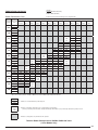
AIRFLOW DATA FOR HIGH STATIC DRIVES
P6SP-090*
HSD kits:
920559 (208-230V, 3Ø, 60 Hz)
920558 (460V, 3Ø, 60 Hz)
Downflow Performance Chart
‡ Indicates Factory Sheave Setting for Pre-configured Units
External Operating @
Unit Static 230 or 460
(in-Wg)
Volts
1.2
1.3
1.4
1.5
1.6
1.7
1.8
1.9
2.0
Adjustable Motor Sheave Setting
Fully
Closed
1/2 Turn
Open
1 Turn
Open
1.5 Turns
Open
2.0 Turns
Open
2.5 Turns
Open
3.0 Turns
Open ‡
3.5 Turns
Open
4.0 Turns
Open
4.5 Turns
Open
5.0 Turns
Open
CFM
3451
3232
3012
RPM
1235
1207
1178
kW
2.28
2.04
1.81
CFM
3292
3043
2794
RPM
1238
1210
1182
kW
2.11
1.87
1.63
CFM
3291
3073
2828
2583
RPM
1269
1243
1214
1184
kW
2.29
1.99
1.76
1.54
CFM
3459
3218
3024
2829
2624
RPM
1324
1300
1274
1247
1219
kW
2.68
2.36
2.11
1.85
1.63
CFM
3267
3044
2853
2662
RPM
1328
1303
1276
1249
kW
2.50
2.22
1.96
1.71
CFM
3278
3081
2884
2685
RPM
1360
1333
1306
1279
kW
2.60
2.36
2.11
1.84
CFM
3343
3140
2916
RPM
1388
1363
1339
kW
2.78
2.49
2.20
CFM
3356
3163
2970
2764
RPM
1417
1392
1367
1343
kW
2.84
2.58
2.32
2.06
CFM
3201
RPM
1422
kW
2.77
5.5 Turns
Open
6.0 Turns
Open
Values includes losses for: Unit Casing, 2” Disposable Filters & Dry Evaporator Coil
Values shown reflect operation at 230V or 460V. For operation at 208V, deduct 0.025 from unit static.
Deduct 250 Cfm for electric heater kits
3862
1159
Indicates a recommended unit operational point
3.03
3493
1017
Indicates an allowable setting that is not recommended for unit operation†
† These operational points should be carefully examined by the installer for proper unit setup and heater operation if used.
2.07
Indicates a setting that is not permitted for unit operation
Table 17. Blower Performance for P6SP-090* Units
(7.5 Ton Downflow Models Only)
21
P6SP-090*
HSD kits:
920559 (208-230V, 3Ø, 60 Hz)
920558 (460V, 3Ø, 60 Hz)
Horizontal Flow Performance Chart*
‡ Indicates Factory Sheave Setting for Pre-configured Units
External Operating @
Unit Static 230 or 460
(in-Wg)
Volts
Adjustable Motor Sheave Setting
4.0 Turns
Open
4.5 Turns
Open
5.0 Turns
Open
CFM
3397
3341
3284
RPM
1178
1171
1163
kW
2.34
2.20
2.06
CFM
3303
3210
3117
RPM
1192
1181
1169
kW
2.24
2.10
1.96
Fully
Closed
1/2 Turn
Open
1 Turn
Open
1.5 Turns
Open
2.0 Turns
Open
2.5 Turns
Open
3.0 Turns
Open ‡
3.5 Turns
Open
5.5 Turns
Open
CFM
1.2
RPM
kW
1.3
1.4
1.5
1.6
1.7
1.8
1.9
2.0
CFM
3434
3214
3065
2916
RPM
1233
1205
1189
1173
kW
2.44
2.15
2.00
1.85
CFM
3296
3098
2911
2723
RPM
1241
1217
1197
1177
kW
2.33
2.11
1.90
1.68
CFM
3406
3168
2929
2717
2505
RPM
1278
1252
1226
1204
1181
kW
2.52
2.27
2.01
1.79
1.57
CFM
3240
3000
2759
RPM
1285
1258
1231
kW
2.41
2.14
1.87
CFM
3334
3088
2869
RPM
1316
1289
1266
kW
2.56
2.25
2.00
CFM
3435
3178
2921
RPM
1347
1321
1294
kW
2.73
2.44
2.15
*Requires horizontal conversion kit. Please refer to unit TSL for kit number.
Values includes losses for: Unit Casing, 2” Disposable Filters & Dry Evaporator Coil
Values shown reflect operation at 230V or 460V. For operation at 208V, deduct 0.025 from unit static.
Deduct 250 Cfm for electric heater kits
3862
1159
Indicates a recommended unit operational point
3.03
3493
1017
Indicates an allowable setting that is not recommended for unit operation†
† These operational points should be carefully examined by the installer for proper unit setup and heater operation if used.
2.07
Indicates a setting that is not permitted for unit operation
Table 18. Blower Performance for P6SP-090* Units
(7.5 Ton Horizontal Models Only)
22
6.0 Turns
Open
P6SP-120* & Q6SP-120* & Q5SN-120*
HSD kits:
920396 (460V, 3Ø, 60 Hz)
920395 (208-230V, 3Ø, 60 Hz)
Downflow Performance Chart
‡ Indicates Factory Sheave Setting for Pre-configured Units
External Operating @
Unit Static 230 or 460
(in-Wg)
Volts
0.9
1.0
1.1
1.2
1.3
1.4
1.5
1.6
1.7
1.8
1.9
2.0
Adjustable Motor Sheave Setting
Fully
Closed
1/2 Turn
Open
1 Turn
Open
1.5 Turns
Open
2.0 Turns
Open
2.5 Turns
Open ‡
3.0 Turns
Open
3.5 Turns
Open
4.0 Turns
Open
4.5 Turns
Open
5.0 Turns
Open
5.5 Turns
Open
6.0 Turns
Open
4174
CFM
4903
4734
4565
4370
RPM
1020
1001
982
962
942
kW
3.01
2.82
2.62
2.42
2.23
3973
CFM
4724
4561
4397
4185
RPM
1023
1005
986
965
944
kW
2.90
2.72
2.54
2.34
2.14
3754
CFM
4583
4385
4186
3970
RPM
1026
1007
988
967
946
kW
2.80
2.60
2.40
2.21
2.03
3479
CFM
4562
4368
4169
3969
3724
RPM
1047
1029
1010
990
969
949
kW
2.92
2.69
2.49
2.29
2.08
1.87
3477
CFM
4571
4366
4161
3942
3723
RPM
1068
1050
1032
1012
993
972
kW
3.01
2.78
2.56
2.35
2.14
1.93
3476
CFM
4387
4171
3954
3715
RPM
1071
1053
1035
1015
995
kW
2.87
2.64
2.42
2.20
1.99
CFM
4354
4164
3960
3757
3493
RPM
1092
1075
1056
1037
1017
kW
3.00
2.74
2.52
2.30
2.07
CFM
4144
3941
3750
3559
RPM
1096
1078
1059
1039
kW
2.86
2.61
2.40
2.18
CFM
4119
3934
3749
3555
RPM
1117
1099
1081
1061
kW
2.96
2.72
2.49
2.28
CFM
4102
3891
3724
3556
RPM
1136
1121
1103
1084
kW
3.00
2.80
2.59
2.37
CFM
3886
3766
3565
RPM
1140
1123
1105
kW
2.89
2.74
2.50
CFM
3862
3762
3534
RPM
1159
1142
1126
kW
3.03
2.82
2.58
Values includes losses for: Unit Casing, 2” Disposable Filters & Dry Evaporator Coil
Values shown reflect operation at 230V or 460V. For operation at 208V, deduct 0.025 from unit static.
Deduct 250 Cfm for electric heater kits
3862
1159
3.03
Indicates a recommended unit operational point
3493
1017
2.07
Indicates an allowable setting that is not recommended for unit operation†
† These operational points should be carefully examined by the installer for proper unit setup and heater operation if used.
Indicates a setting that is not permitted for unit operation
Table 19. Blower Performance for P6SP-120*, Q6SP-120*, & Q5SN-120* Units
(10 Ton Downflow Models Only)
23
P6SP-120* & Q6SP-120* & Q5SN-120*
HSD kits:
920395 (208-230V, 3Ø, 60 Hz)
920396 (460V, 3Ø, 60 Hz)
Horizontal Flow Performance Chart*
‡ Indicates Factory Sheave Setting for Pre-configured Units
External Operating @
Unit Static 230 or 460
(in-Wg)
Volts
0.9
1.0
1.1
1.2
1.3
1.4
1.5
1.6
1.7
1.8
1.9
2.0
Adjustable Motor Sheave Setting
Fully
Closed
1/2 Turn
Open
1 Turn
Open
1.5 Turns
Open
2.0 Turns
Open
2.5 Turns
Open ‡
3.0 Turns
Open
3.5 Turns
Open
4.0 Turns
Open
4.5 Turns
Open
5.0 Turns
Open
5.5 Turns
Open
6.0 Turns
Open
4685
CFM
4904
RPM
956.5
937
kW
2.81
2.58
4520
CFM
4914
4717
RPM
980
959
938
kW
2.94
2.7
2.46
4317
CFM
4738
4527
RPM
982
961
940
kW
2.8
2.57
2.34
4073
CFM
4784
4561
4317
RPM
1002.5
984
964
944
kW
2.94
2.66
2.43
2.19
3871
CFM
4568
4378
4125
RPM
1005.5
987
967
946
kW
2.79
2.53
2.29
2.04
3647
CFM
4558
4352
4147
3897
RPM
1027
1009
990
970
949
kW
2.90
2.65
2.40
2.16
1.93
3595
CFM
4358
4137
3915
RPM
1030
1012
993
973
kW
2.74
2.50
2.26
2.02
3363
CFM
4326
4135
3749
RPM
1052
1033
1016
999
kW
2.87
2.60
2.35
2.10
CFM
4327
4120
3912
3361
RPM
1072
1054
1036
1020
kW
2.96
2.71
2.46
2.20
CFM
4137
3889
3640
RPM
1074
1057
1040
kW
2.78
2.54
2.29
CFM
4068
3824
3313
RPM
1096
1077
1063
kW
2.87
2.60
2.26
CFM
4083
3797
3511
RPM
1118
1099
1080
kW
2.93
2.68
2.42
*Requires horizontal conversion kit. Please refer to unit TSL for kit number.
Values includes losses for: Unit Casing, 2” Disposable Filters & Dry Evaporator Coil
Values shown reflect operation at 230V or 460V. For operation at 208V, deduct 0.025 from unit static.
Deduct 250 Cfm for electric heater kits
3862
1159
Indicates a recommended unit operational point
3.03
3493
1017
Indicates an allowable setting that is not recommended for unit operation†
† These operational points should be carefully examined by the installer for proper unit setup and heater operation if used.
2.07
Indicates a setting that is not permitted for unit operation
Table 20. Blower Performance for P6SP-120*, Q6SP-120*, & Q5SN-120* Units
(10 Ton Horizontal Models Only)
24
Q6SP-090* & Q5SN-090*
HSD kits
920394 (208-230V, 3Ø, 60 Hz)
920608 (460V, 3Ø, 60 Hz)
Downflow Performance Chart
‡ Indicates Factory Sheave Setting for Pre-configured Units
External Operating @
Unit Static 230 or 460
(in-Wg)
Volts
Adjustable Motor Sheave Setting
Fully
Closed
1/2 Turn
Open
1 Turn
Open
1.5 Turns
Open ‡
2.0 Turns
Open
2.5 Turns
Open
3.0 Turns
Open
3.5 Turns
Open
4.0 Turns
Open
4.5 Turns
Open
5.0 Turns
Open
CFM
3725
3273
2820
RPM
937
906
875
kW
2.03
1.80
1.56
CFM
3490
5.5 Turns
Open
6.0 Turns
Open
CFM
0.9
RPM
kW
CFM
1.0
RPM
kW
1.1
1.2
1.3
1.4
1.5
1.6
1.7
1.8
1.9
2.0
RPM
938
kW
2.18
CFM
3720
3370
RPM
986
965
943
kW
2.42
2.22
2.01
2540
3020
CFM
3480
3010
RPM
988
968
947
kW
2.24
2.04
1.84
CFM
3775
3393
RPM
1032
1012
992
kW
2.36
2.21
2.05
2540
3010
CFM
3525
3033
RPM
1035
1016
996
kW
2.23
2.06
1.89
CFM
3750
3400
3050
RPM
1074
1057
1040
kW
2.48
2.27
2.05
CFM
3900
3713
3525
3050
2575
RPM
1105
1092
1079
1062
1044
kW
2.95
2.69
2.43
2.16
1.88
CFM
3700
3375
3050
RPM
1109
1097
1084
kW
2.74
2.47
2.20
CFM
3100
RPM
1117
kW
2.33
Values includes losses for: Unit Casing, 2” Disposable Filters & Dry Evaporator Coil
Values shown reflect operation at 230V or 460V. For operation at 208V, deduct 0.025 from unit static.
Deduct 250 Cfm for electric heater kits
3862
1159
Indicates a recommended unit operational point
3.03
3493
1017
Indicates an allowable setting that is not recommended for unit operation†
† These operational points should be carefully examined by the installer for proper unit setup and heater operation if used.
2.07
Indicates a setting that is not permitted for unit operation
Table 21. Blower Performance for Q6SP-090* & Q5SN-090* Units
(7.5 Ton Downflow Models Only)
25
Q6SP-090* & Q5SN-090*
HSD kits:
920394 (208-230V, 3Ø, 60 Hz)
920608 (460V, 3Ø, 60 Hz)
Horizontal Flow Performance Chart*
‡ Indicates Factory Sheave Setting for Pre-configured Units
External Operating @
Unit Static 230 or 460
(in-Wg)
Volts
Adjustable Motor Sheave Setting
Fully
Closed
1/2 Turn
Open
1 Turn
Open
1.5 Turns
Open ‡
2.0 Turns
Open
2.5 Turns
Open
3.0 Turns
Open
3.5 Turns
Open
4.0 Turns
Open
4.5 Turns
Open
5.0 Turns
Open
5.5 Turns
Open
CFM
0.9
RPM
kW
CFM
1.0
RPM
kW
3890
CFM
1.1
1.2
1.3
1.4
1.5
1.6
1.7
1.8
RPM
891
kW
1.93
CFM
4140
3883
RPM
937
915
893
kW
2.28
2.05
1.82
3260
CFM
3910
3585
RPM
939
918
897
kW
2.15
1.91
1.66
CFM
4150
3895
RPM
983
963
942
kW
2.45
2.23
2.00
2.0
3640
3250
CFM
3940
3595
RPM
985
965
945
kW
2.33
2.08
1.82
CFM
3630
RPM
988
kW
2.15
CFM
3960
3355
RPM
1031
1014
996
kW
2.52
2.13
1.74
CFM
3690
RPM
1035
2750
2.35
kW
1.9
3625
CFM
3975
3388
2800
RPM
1073
1059
1044
kW
2.73
2.33
1.92
CFM
3059
RPM
1083
kW
2.22
*Requires horizontal conversion kit. Please refer to unit TSL for kit number.
Values includes losses for: Unit Casing, 2” Disposable Filters & Dry Evaporator Coil
Values shown reflect operation at 230V or 460V. For operation at 208V, deduct 0.025 from unit static.
Deduct 250 Cfm for electric heater kits
3862
1159
Indicates a recommended unit operational point
3.03
3493
1017
Indicates an allowable setting that is not recommended for unit operation†
† These operational points should be carefully examined by the installer for proper unit setup and heater operation if used.
2.07
Indicates a setting that is not permitted for unit operation
Table 22. Blower Performance for Q6SP-090* & Q5SN-090* Units
(7.5 Ton Horizontal Models Only)
26
6.0 Turns
Open
R4GM & R6GN-150* Series
HSD kits:
918799 (208-230V, 3Ø, 60 Hz)
920637 (460V, 3Ø, 60 Hz)
Blower Performance Chart
‡ Indicates Factory Sheave Setting for Pre-configured Units
External Operating @
Unit Static 230 or 460
(in-Wg)
Volts
Adjustable Motor Sheave Setting
4.0 Turns
Open ‡
4.5 Turns
Open
5.0 Turns
Open
CFM
5350
5100
4850
RPM
1188
1168
1148
kW
3.20
2.98
2.75
Fully
Closed
1/2 Turn
Open
1 Turn
Open
1.5 Turns
Open
2.0 Turns
Open
2.5 Turns
Open
3.0 Turns
Open
3.5 Turns
Open
5.5 Turns
Open
6.0 Turns
Open
CFM
0.9
RPM
kW
CFM
1.0
RPM
kW
1.1
1.2
1.3
1.4
1.5
1.6
1.7
1.8
1.9
CFM
5225
5000
4700
4400
RPM
1210
1189
1169
1148
kW
3.23
3.00
2.75
2.50
CFM
5100
4850
4600
4250
3900
RPM
1231
1211
1190
1170
1149
kW
3.25
3.00
2.75
2.53
2.30
CFM
5300
5050
4800
4500
4200
RPM
1271
1252
1232
1212
1191
kW
3.55
3.33
3.10
2.85
2.60
CFM
5400
5150
4900
4650
4400
4050
3700
RPM
1313
1293
1273
1253
1233
1213
1192
kW
3.80
3.55
3.30
3.09
2.87
2.59
2.30
CFM
5375
5000
4725
4450
4175
3900
3600
RPM
1334
1314
1295
1275
1255
1235
1214
kW
3.90
3.60
3.35
3.10
2.86
2.62
2.35
CFM
5350
4925
4500
4250
4000
RPM
1355
1336
1316
1296
1276
kW
4.00
3.70
3.40
3.15
2.90
CFM
4850
4475
4100
3725
RPM
1357
1338
1318
1297
kW
3.75
3.48
3.20
2.95
CFM
4400
4000
3600
RPM
1359
1340
1320
kW
3.50
3.23
2.95
CFM
2.0
RPM
kW
Values include losses for: Unit Casing, 2” Disposable Filters, Dry Evaporator Coil & Installed Heat Exchanger
Values shown reflect operation at 230V or 460V. For operation at 208V, deduct 0.025 from unit static.
3862
1159
Indicates a recommended unit operational point
3.03
3493
1017
Indicates an allowable setting that is not recommended for unit operation†
† These operational points should be carefully examined by the installer for proper unit setup and heater operation if used.
2.07
Indicates a setting that is not permitted for unit operation
Table 23. Blower Performance for R4GM & R6GN-150* Units
(15 Ton Models Only)
27
R4GM & R6GN-180* Series
HSD kits:
918800 (208-230/460V, 3Ø, 60 Hz)
Blower Performance Chart
‡ Indicates Factory Sheave Setting for Pre-configured Units
External Operating @
Unit Static 230 or 460
(in-Wg)
Volts
Adjustable Motor Sheave Setting
3.0 Turns
Open
3.5 Turns
Open
4.0 Turns
Open ‡
4.5 Turns
Open
5.0 Turns
Open
CFM
5800
5575
5350
5100
4850
RPM
1228
1208
1188
1168
1148
kW
3.65
3.43
3.20
2.98
2.75
Fully
Closed
1/2 Turn
Open
1 Turn
Open
1.5 Turns
Open
2.0 Turns
Open
2.5 Turns
Open
5.5 Turns
Open
CFM
0.9
RPM
kW
CFM
1.0
RPM
kW
1.1
1.2
1.3
1.4
1.5
1.6
1.7
1.8
1.9
CFM
6200
5850
5500
5250
5000
4700
4400
RPM
1270
1250
1230
1210
1189
1169
1148
kW
4.1
3.80
3.50
3.25
3.00
2.75
2.50
CFM
6100
5850
5600
5350
5100
4850
4600
RPM
1309
1290
1271
1251
1231
1211
1190
kW
4.25
4.03
3.80
3.55
3.30
3.03
2.75
CFM
5800
5550
5300
5050
4800
4500
4200
RPM
1310
1291
1272
1252
1232
1211.5
1191
kW
4.00
3.78
3.55
3.33
3.10
2.85
2.60
CFM
6000
5700
5400
5150
4900
4650
4400
RPM
1353
1333
1312
1293
1273
1253
1233
kW
4.45
4.13
3.80
3.55
3.30
3.09
2.87
CFM
5650
5325
5000
4725
4450
RPM
1354
1334
1314
1295
1275
kW
4.25
3.93
3.60
3.35
3.10
CFM
5350
4925
4500
RPM
1355
1336
1316
kW
4.00
3.70
3.40
CFM
4850
4475
4100
RPM
1357
1338
1318
kW
3.75
3.48
3.20
CFM
4400
RPM
1359
kW
3.50
CFM
2.0
RPM
kW
Values include losses for: Unit Casing, 2” Disposable Filters, Dry Evaporator Coil & Installed Heat Exchanger
Values shown reflect operation at 230V or 460V. For operation at 208V, deduct 0.025 from unit static.
3862
1159
Indicates a recommended unit operational point
3.03
3493
1017
Indicates an allowable setting that is not recommended for unit operation†
† These operational points should be carefully examined by the installer for proper unit setup and heater operation if used.
2.07
Indicates a setting that is not permitted for unit operation
Table 24. Blower Performance for R4GM & R6GN-180* Units
(15 Ton Models Only)
28
6.0 Turns
Open
R6GP-090*-200C
HSD kits:
920559 (208-230V, 3Ø, 60 Hz)
920558 (460V, 3Ø, 60 Hz)
Downflow Performance Chart
‡ Indicates Factory Sheave Setting for Pre-configured Units
Adjustable Motor Sheave Setting
External Operating @
Unit Static 230 or 460
(in-Wg)
Volts
1.2
1.3
1.4
1.5
1.6
1.7
1.8
1.9
2.0
Fully
Closed
1/2 Turn
Open
1 Turn
Open
1.5 Turns
Open
2.0 Turns
Open
2.5 Turns
Open
3.0 Turns
Open ‡
3.5 Turns
Open
4.0 Turns
Open
4.5 Turns
Open
5.0 Turns
Open
CFM
3417
3226
3035
RPM
1232
1203
1173
kW
2.32
2.10
1.88
CFM
3258
3055
2852
RPM
1235
1205
1175
kW
2.15
1.96
1.78
CFM
3448
3267
3085
2856
2626
RPM
1292
1265
1237
1208
1178
kW
2.47
2.24
2.01
1.82
1.64
CFM
3300
3099
2898
2677
RPM
1295
1268
1240
1211
kW
2.33
2.10
1.86
1.66
CFM
3164
2932
2705
RPM
1299
1271
1243
kW
2.24
1.96
1.69
CFM
3392
3178
2963
2756
RPM
1356
1329
1302
1274
kW
2.63
2.34
2.06
1.80
CFM
3422
3214
2997
RPM
1384
1358
1332
kW
2.75
2.53
2.26
CFM
3437
3251
3016
RPM
1414
1389
1364
kW
2.88
2.58
2.42
CFM
3306
3033
RPM
1419
1394
kW
2.76
2.45
5.5 Turns
Open
6.0 Turns
Open
Values include losses for: Unit Casing, 2” Disposable Filters, Dry Evaporator Coil & Installed Heat Exchanger
Values shown reflect operation at 230V or 460V. For operation at 208V, deduct 0.025 from unit static.
3862
1159
Indicates a recommended unit operational point
3.03
3493
1017
Indicates an allowable setting that is not recommended for unit operation†
† These operational points should be carefully examined by the installer for proper unit setup and heater operation if used.
2.07
Indicates a setting that is not permitted for unit operation
Table 25. Blower Performance for R6GP-090*-200C Units
(7.5 Ton Downflow Models Only)
29
R6GP-090*-200C
HSD kits:
920559 (208-230V, 3Ø, 60 Hz)
920558 (460V, 3Ø, 60 Hz)
Horizontal Flow Performance Chart*
‡ Indicates Factory Sheave Setting for Pre-configured Units
External Operating @
Unit Static 230 or 460
(in-Wg)
Volts
1.2
Adjustable Motor Sheave Setting
Fully
Closed
1/2 Turn
Open
1 Turn
Open
1.5 Turns
Open
2.0 Turns
Open
2.5 Turns
Open
3.0 Turns
Open ‡
3.5 Turns
Open
4.0 Turns
Open
4.5 Turns
Open
CFM
3524
RPM
1160
1.4
1.5
1.6
1.7
1.8
1.9
2.0
5.5 Turns
Open
2.16
kW
1.3
5.0 Turns
Open
CFM
3495
3344
RPM
1190
1167
kW
2.30
2.08
CFM
3491
3339
3186
RPM
1220
1196
1171
kW
2.41
2.17
1.93
CFM
3545
3316
3137
2958
RPM
1247
1226
1202
1178
kW
2.53
2.27
2.07
1.86
CFM
3391
3145
2941
2736
RPM
1254
1232
1208
1183
kW
2.37
2.14
1.90
1.66
CFM
3458
3215
2971
2736
RPM
1282
1260
1237
1214
kW
2.54
2.28
2.01
1.74
CFM
3538
3273
3016
2758
RPM
1313
1289
1265
1241
kW
2.69
2.39
1.92
1.44
CFM
3383
3123
2840
RPM
1319
1296
1272
kW
2.55
2.24
1.74
CFM
3543
3447
3181
2915
RPM
1364
1350
1325
1299
kW
2.87
2.65
2.36
2.07
*Requires horizontal conversion kit. Please refer to unit TSL for kit number.
Values include losses for: Unit Casing, 2” Disposable Filters, Dry Evaporator Coil & Installed Heat Exchanger
Values shown reflect operation at 230V or 460V. For operation at 208V, deduct 0.025 from unit static.
3862
1159
Indicates a recommended unit operational point
3.03
3493
1017
Indicates an allowable setting that is not recommended for unit operation†
† These operational points should be carefully examined by the installer for proper unit setup and heater operation if used.
2.07
Indicates a setting that is not permitted for unit operation
Table 26. Blower Performance for R6GP-090*-200C Units
(7.5 Ton Horizontal Models Only)
30
6.0 Turns
Open
R6GP-120*-235C
HSD kits:
920395 (208-230V, 3Ø, 60 Hz)
920396 (460V, 3Ø, 60 Hz)
Downflow Performance Chart
‡ Indicates Factory Sheave Setting for Pre-configured Units
External Operating @
Unit Static 230 or 460
(in-Wg)
Volts
Adjustable Motor Sheave Setting
Fully
Closed
1/2 Turn
Open
1 Turn
Open
1.5 Turns
Open
2.0 Turns
Open
2.5 Turns
Open
3.0 Turns
Open ‡
3.5 Turns
Open
4.0 Turns
Open
4.5 Turns
Open
5.0 Turns
Open
5.5 Turns
Open
6.0 Turns
Open
CFM
0.9
RPM
kW
CFM
1.0
RPM
kW
4672
CFM
1.1
1.2
1.3
1.4
1.5
1.6
1.7
1.8
1.9
2.0
RPM
975
kW
2.65
CFM
4673
RPM
998
979
kW
2.75
2.50
4227
4466
CFM
4630
4429
RPM
1018
1000
982
kW
2.90
2.65
2.40
3988
CFM
4611
4394
4191
RPM
1039
1020
1003
985
kW
2.95
2.70
2.50
2.30
3260
CFM
4613
4391
4168
3714
RPM
1058
1041
1023
1006
989
kW
3.10
2.85
2.60
2.38
2.15
CFM
4379
4181
3982
3257
RPM
1061
1046
1031
1012
kW
2.90
2.70
2.50
2.25
CFM
4480
4233
3976
3718
RPM
1087
1070
1053
1036
kW
3.10
2.80
2.55
2.30
CFM
4244
3996
3683
3370
RPM
1089
1072
1056
1039
kW
2.90
2.60
2.40
2.20
CFM
4278
4011
3744
RPM
1111
1093
1075
kW
3.10
2.80
2.50
CFM
4252
4016
3455
RPM
1130
1115
1097
kW
3.10
2.90
2.50
Values include losses for: Unit Casing, 2” Disposable Filters, Dry Evaporator Coil & Installed Heat Exchanger
Values shown reflect operation at 230V or 460V. For operation at 208V, deduct 0.025 from unit static.
3862
1159
Indicates a recommended unit operational point
3.03
3493
1017
Indicates an allowable setting that is not recommended for unit operation†
† These operational points should be carefully examined by the installer for proper unit setup and heater operation if used.
2.07
Indicates a setting that is not permitted for unit operation
Table 27. Blower Performance for R6GP-120*-235C Units
(10 Ton Downflow Models Only)
31
R6GP-120*-235C
HSD kits:
920395 (208-230V, 3Ø, 60 Hz)
920396 (460V, 3Ø, 60 Hz)
Horizontal Flow Performance Chart*
‡ Indicates Factory Sheave Setting for Pre-configured Units
External Operating @
Unit Static 230 or 460
(in-Wg)
Volts
Adjustable Motor Sheave Setting
Fully
Closed
1/2 Turn
Open
1 Turn
Open
1.5 Turns
Open
2.0 Turns
Open
2.5 Turns
Open
3.0 Turns
Open ‡
3.5 Turns
Open
4.0 Turns
Open
4.5 Turns
Open
5.0 Turns
Open
5.5 Turns
Open
CFM
0.9
RPM
kW
CFM
1.0
RPM
kW
4692
CFM
1.1
1.2
1.3
1.4
1.5
1.6
1.7
1.8
1.9
2.0
RPM
969
kW
2.75
CFM
4492
RPM
973
kW
2.61
CFM
4535
RPM
998
976
kW
2.79
2.52
4066
4305
CFM
4569
4318
RPM
1022
1001
980
kW
2.92
2.66
2.39
3799
CFM
4308
4054
RPM
1027
1006
984
kW
2.76
2.49
2.22
3510
CFM
4368
4084
3797
RPM
1050
1030
1009
988
kW
2.89
2.61
2.34
2.07
CFM
4422
4120
3817
3493
RPM
1071
1053
1034
1014
kW
3.03
2.74
2.44
2.17
CFM
4177
3875
3573
RPM
1075
1056
1037
kW
2.89
2.58
2.27
CFM
4127
3908
3296
RPM
1098
1079
1063
kW
2.96
2.72
2.31
CFM
4115
3866
3616
RPM
1118
1101
1083
kW
3.01
2.76
2.51
*Requires horizontal conversion kit. Please refer to unit TSL for kit number.
Values include losses for: Unit Casing, 2” Disposable Filters, Dry Evaporator Coil & Installed Heat Exchanger
Values shown reflect operation at 230V or 460V. For operation at 208V, deduct 0.025 from unit static.
3862
1159
Indicates a recommended unit operational point
3.03
3493
1017
Indicates an allowable setting that is not recommended for unit operation†
† These operational points should be carefully examined by the installer for proper unit setup and heater operation if used.
2.07
Indicates a setting that is not permitted for unit operation
Table 28. Blower Performance for R6GP-120*-235C Units
(10 Ton Horizontal Models Only)
32
6.0 Turns
Open
UNIT
MODEL
GAS
TYPE
R6GP-072*-100C
R6GP-072*-166C
R6GP-090*-200C
R6GP-120*-235C
R6GN-150*-180C
R6GN-150*-270C
R6GN-180*-270C
R6GN-180*-315C
HEATING
INPUT
HEATING
OUTPUT
Natural Gas
100,000
80,000
Propane (LP)
85,000
68,000
Natural Gas
166,000
133,000
Propane (LP)
141,000
112,800
Natural Gas
200,000
157,000
Propane (LP)
175,000
137,000
Natural Gas
235,000
188,000
Propane (LP)
205,000
164,000
Natural Gas
180,000
144,000
Propane (LP)
153,000
122,000
Natural Gas
270,000
216,000
Propane (LP)
230,000
184,000
Natural Gas
270,000
216,000
Propane (LP)
230,000
184,000
Natural Gas
315,000
252,000
Propane (LP)
268,000
214,000
HEATING
RISE
RANGE
15 - 45
35 - 65
30 - 60
25 - 55
20 - 50
30 - 60
30 - 60
30 - 60
CFM RANGE
SCFM
1950
2100
2250
2400
2550
2700
Rise (º F)†
38
32
35
30
33
28
31
26
29
25
27
23
SCFM
1950
2100
2250
2400
2550
2700
Rise (º F)†
63
54
59
50
55
46
51
44
48
41
46
39
SCFM
2425
2625
2800
3000
3188
3375
Rise (º F)†
60
52
55
48
52
45
48
42
46
40
43
38
SCFM
3250
3500
3750
4000
4250
4500
Rise (º F)†
54
47
50
43
46
40
44
38
41
36
39
34
SCFM
4063
4375
4688
5000
5313
5625
Rise (º F)†
33
28
30
26
28
24
27
23
25
21
24
20
SCFM
4063
4375
4688
5000
5313
5625
Rise (º F)†
49
42
46
39
43
36
40
34
38
32
36
30
SCFM
4875
5250
5625
6000
6375
6750
Rise (º F)†
41
35
38
32
36
30
33
28
31
27
30
25
SCFM
4875
5250
5625
6000
6375
6750
Rise (º F)†
48
41
44
38
41
35
39
33
37
31
35
29
† At Elevations of 2,000 Ft or less
Table 29. Gas Heat Exchanger Temperature Rise Data
H5HK
MODEL
009Q
009S
018Q
018S
030Q
030S
035Q
035S
VOLTAGE
KW
BTUH
208
6.8
23,202
240
9.0
30,708
480
9.9
33,779
208
13.1
44,697
240
17.4
59,369
480
18.0
61,416
208
21.6
73,699
240
28.8
98,266
480
28.8
98,266
208
26.2
89,394
240
34.8
118,738
480
34.8
118,738
CFM RANGE
SCFM
Rise (º F)
Rise (º F)
Rise (º F)
Rise (º F)
2100
2500
2900
3300
3700
4500
10
9
7
7
6
5
14
11
10
9
8
6
15
13
11
9
8
7
20
17
14
13
11
9
26
22
19
17
15
12
27
23
20
17
15
13
32
27
24
21
18
15
43
36
31
28
25
20
43
36
31
28
25
20
39
33
29
25
22
18
52
44
38
33
30
24
52
44
38
33
30
24
Table 30. Electric Heater Kit Temperature Rise Data
33
3
2
1
P6SP Series - 072/090 Units
On Drive Kits (for P6SP Series Units) that require the addition of an external overload relay.
A) Use the included 97” wires to route power from the terminal block (1) to overload relay (2).
B) Use the 19” wires to route power from relay (2) to the blower contactor (3).
C) Discard original wires powering the blower contactor. Bundle all wires neatly.
34
35
INSTALLATION / PERFORMANCE CHECK LIST
INSTALLATION ADDRESS:
CITY _______________________ STATE _____________________
UNIT MODEL # ____________________________________________
UNIT SERIAL # ____________________________________________
HSDK PART # _____________________________________________
INSTALLER NAME:
CITY _______________________
STATE ________________
BLOWER SYSTEM:
Blower Motor HP:______________________________________
Sheave Setting: ________________________________turns open
System Static:______________________________E.S.P. (in -Wg)
ELECTRIC HEAT / GAS HEAT EXCHANGER:
Heater Kit Installed?
YES
NO
Heater Kit Model #: _____________________________________
Furnace Input: _____________________________________(Btuh)
Return Air Temp: ____________________________________°F
Supply Air Temp: ____________________________________°F
Temperature Rise: ___________________________________°F
INSTALLER:
PLEASE LEAVE THESE INSTALLATION
INSTRUCTIONS WITH THE OWNER
¢708800{¤
Specifications & illustrations subject to change without notice or incurring obligations.
O’ Fallon, MO | Printed in U.S.A. (08/10)
7088000 (Replaces 708435A)