1
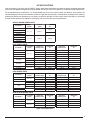
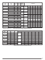
RANGE OF
PROTECTION
(AMPS)
RELAY PART
NUMBER
REQUIRED
MOUNTING PLATE
1.4 - 2.0
1.8 - 2.5
624728
624729
622032
622032
2.8 - 4.0
622034
622032
3.5 - 5.0
622075
622032
5.5 - 8.0
7.0 - 10.0
622031
622077
622032
622032
11.0 - 16.0
622082
622083
6-1
0 TO
NEL
Over
Mou load Rela
nting
Loca y
N PA
tion
CKA
GED
A
(6 TO IR CON
DIT
N MO
DEL ONER C
SHO
WN) ONTROL
6-1
0 TO
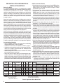
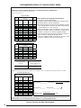
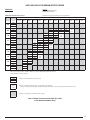
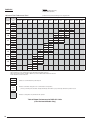
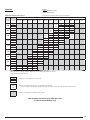
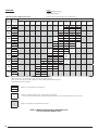
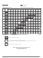
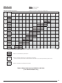
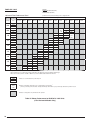
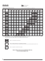
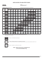
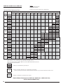
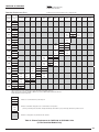
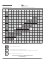
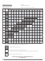
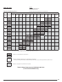
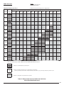
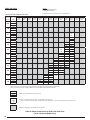
Table 4. Overload Relay Data
(3Ø Motor External Protectors)
EXTERNAL MOTOR OVERLOADS
Application
Siemens 3RU11 overload relays provide overload protection
for three-phase inductive motors with rated currents of up to
100A (75HP, AC-3, 480V). Most NORDYNE motors do not
require an external motor protector. Refer to Table 3 (page 4)
to determine which kits require protectors.
N PA
CKA
GED
(6 TO GAS / E
LE
N MO
DEL CTRIC C
O
SHO
WN) NTROL
PA
PAN
E
L
Over
Mou load Rela
nting
Loca y
tion
12.5
- 15
TON
C
ONT
ROL
PAN
E
L
Auxiliary Contacts
The overload relays are equipped with a NC contact for deenergizing the contactor and a NO contact for signalling an
overload trip. The breaking capacity of the switching contacts
is very high so that the contactor coils can be switched directly.
Trip Class
The 3RU11 overload relays are designed in accordance with
trip class 10 (e.g. The protector will trip in less than 10 seconds
at 6 times the trip current setting (FLA).
Phase Failure Sensitivity
A phase failure sensitivity function is integrated in to the relay
in order to provide increased protection in the event of a phase
failure, i.e. faster tripping in the event of a single-phase condition.
Over
Mou load Rela
nting
Loca y
tion
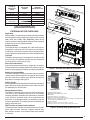
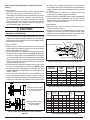
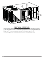
Figure 1. Overload Relay Mounting Locations
Mounting
Hole
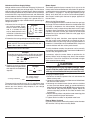
Setting the Overload Relay
The current setting dial can be accessed once the transparent,
sealable cover has been opened. The overload relay must be
set at the rated Service Factor Amps (SFA) of the motor for
the proper unit voltage. See Figure 2.
1
5
2
6
3
STOP Function
Pressing the red STOP button on the overload relay momentarily
opens the NC trip contact. No other contacts and/or functions
are affected by this STOP button.
Manual/Automatic Reset
The RESET button/mechanism features trip-free operation.
This means that the overload relay will trip on an overload
condition regardless of whether the reset button is pushed in
or not. Manual or automatic reset can be selected with the
blue button. The appropriate setting is selected by pressing
and turning the button. This setting can then be locked by the
sliding transparent cover.
TEST Function & Switch Position Indicator
The switch position indicator also incorporates a test function
which, when activated, simulates a tripped overload relay.
Both auxiliary contacts are actuated and the switch position
is indicated.
Mounting
Hole
7
8
4
MOUNTING PLATE
9
3RU111 OVERLOAD RELAY
1. Equipment identifying marker
2. Manual/Automatic RESET selector switch
3. STOP button
4. Complete Catalog # on front of device
5. Switch position indicator and TEST function
6. Transparent cover, sealable (secures the current setting screw, TEST function
and manual/automatic RESET position)
7. Current setting dial
8. Terminal for contactor coil (when mounted on contactor)
9. Terminal for contactor aux. contacts (when mounted on contactor)
Figure 2. Overload Relay & Mounting Plate
5