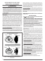
1
PRE-INSTALLATION INFORMATION &
INSTALLATION METHOD
Before You Begin
It is recommended that prior to a kit selection for a retrofit
installation, the existing duct system be inspected for security
and possible improvements. The removal of flexible duct
sections or replacement of under sized ducts can significantly
improve a buildings air distribution system for increased unit
efficiency, correction of room stratification issues for personal
comfort and reduction of equipment noise levels transferred
through the ducts.
Some local codes require testing a buildings duct system for
external air infiltration and correcting any deficient structures.
Commercial duct systems should be designed for compliance
with the guidelines given in the ASHRAE Handbooks, ACCA
Manual Q, SMACNA manuals or as specified by any applicable
NFPA and local codes or ordinances that may apply. Improving
an existing duct system could be more cost effective then
increasing the units airflow when weighed against the increased
energy cost for the designed life of the equipment.
Always make sure all equipment installation instructions are
on-hand and reviewed prior to the commencement of any work
for the unit and all field installed accessories.This accessory kit
should be installed prior to the installation of any economizers,
air-dampers, or other kits that require the blower operation
for final setup. On roof top installations, these kits could be
partially installed at ground level prior to the final unit placement
in order to reduce the number of crane operations required.
Pre-Installation Checklist
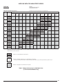
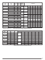
• Verify the HSDK matches the unit application and building
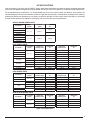
voltage requirements in Table 2 (page 3).
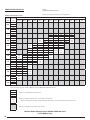
• Inspect the kit and verify the contents to Table 1 (page 1).
• Inspect the duct system for security, air leakage or infiltration,
and that it is properly constructed for the airflow/pressure
requirements of the HSDK.
• Review all equipment and accessory installation instructions
prior to beginning the installation.
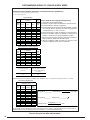
• Verify that the unit supply wiring, unit disconnect & overcurrent protection is sized properly for the addition of the
HSDK and any other accessory kits that will utilize the same
electrical circuit. See Figure 9 (page 10) for recommended
procedure on how to determine the proper 3 phase wire size.
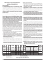
MOTOR
RATED
PART
POLES
HP
NUMBER
621819
621820
3
3
4
4
622006
5
4
622026
2
4
622074
3
4
622254
622305
2
1.5
4
4
NOTES:
VOLTAGE
200-230
460
208-230/460
190 / 380
208-230/460
208-230/460
190 / 380
208-230/460
208-230/460
FLA = Full Load Amps
SF = Service Factor
† Approximate Efficiency
HZ
60
60
60
50
60
60
50
60
60
Ø
3
3
3
3
3
3
3
3
3
HSDK Installation Method
1. Set the thermostat and unit disconnect(s) to the OFF position.
Verify that the unit has been isolated from all electrical
power sources. For HSDK’s that do not require a motor
replacement, go to step 6.
2. Open/remove the access panels for the units control
panel, blower compartment and field wiring compartments.
NOTE: Never lift or hoist a unit without the access panels
installed or closed and securely attached with all of the
screws supplied from the factory. Refer to the unit installation
instructions for additional details if necessary.
3. Locate the blower motor and trace the motor wires back to
the blower motor contactor or external motor relay. Carefully
cut any zip-ties to free the motor wires from the unit or wiring
harness.
4. Disconnect the motor wires from the overload relay or
contactor T1, T2 & T3 terminals or box lugs.
5. Remove the factory motor & lead assembly from the motor
mounting plate and install the HSDK motor & lead assembly
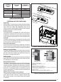
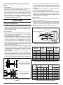
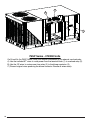
in the unit. See Figure 1 (page 5) for overload relay mounting
locations.
6. Install the motor overload relay (if required) as described
on page 5. Re-route the blower motor wires to the overload
or blower contactor and secure with the supplied zip-ties.
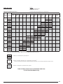
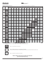
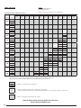
• Refer to Table 1 to determine the HSDK motor part number
and then Table 3 to determine the service factor amps (SFA)
for the HSDK motor at the correct unit supply voltage. Set
the external overload relay to the motor SFA for that voltage.
NOTE: Replacement overload relay part numbers can be
found using the data in Tables 3 & 4.
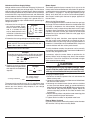
7. Verify the proper operation of the motor sheave. Refer to the
blower chart called out for the application in Table 1 and set
the sheave to the proper set-point. Install the HSDK blower
pulley and belt and reference the instructions on pages 6 - 8.
Tighten the belt and secure the assembly.
8. Verify that all electrical connections have been made and
wiring properly secured. Complete the instructions on
verifying the electrical phase balance and blower rotation
direction (pages 8 - 9).
9. After the completion of any other unit or accessory installation
requirements, close or re-install the blower compartment
access panel and restore the electrical power to the unit.
Verify that the unit is delivering the proper airflow as described
on pages 8 - 9.
10. Replace all other access panels and refer to the unit
installation instructions to complete the installation and
place the unit into normal service.
RATED
RPM
NEMA
NOM.
EFF.
NEMA
FRAME
SIZE
1725
1725
1760
1445
1755
1765
1455
1725
1755
81% †
81% †
87.5%
84%
85.5%
86.5%
84%
84% †
86.5%
145T
145T
184T
145T
182T
145T
145T
MOTOR AMPERAGE
FLA
SF
SFA
9.10 - 8.90
4.4
14.0 - 13.4 / 6.7
15.9 / 7.9
5.8 - 5.5 / 2.8
8.8 - 8.6 / 4.4
9.8 / 4.9
6.2 - 5.8 / 2.9
4.4 - 4.2 / 2.1
1.15
1.15
1.15
1.00
1.15
1.15
1.00
1.15
1.15
10.2 - 9.70
4.8
15.0 - 15.0 / 7.5
15.9 / 7.9
6.6 - 6.1 / 3.1
10.1 - 9.9 / 5.0
9.8 / 4.9
7.0 - 6.6 / 3.3
5.0 - 4.6 / 2.3
SFA = Service Factor Amps
Nom. Eff. = Nominal Efficiency
Table 3. High Static Drive Motor Data
4
REQUIRED
EXTERNAL
PROTECTOR
- N/A - N/A YES
YES
YES
- N/A YES