1
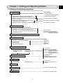
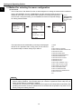
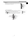
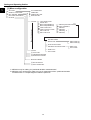
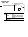
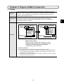
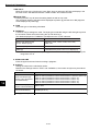
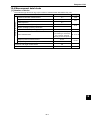
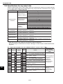
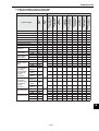
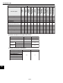
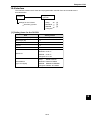
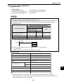
PC Function
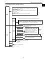
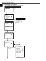
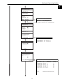
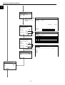
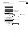
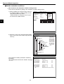
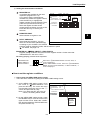
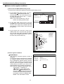
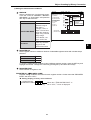
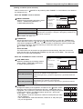
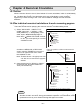
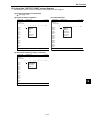
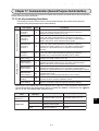
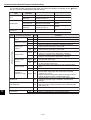
[1] Power ON sequence
The parallel output terminals (Y0 to Y7) are reset, and the data memories (input relays, output relays,
auxiliary relays, timer and counter) are cleared.
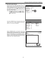
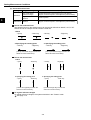
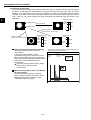
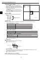
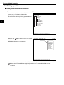
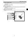
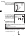
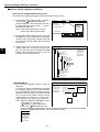
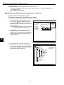
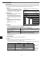
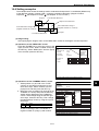
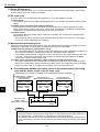
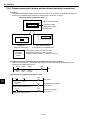
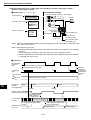
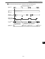
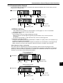
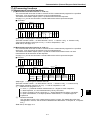
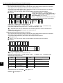
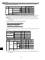
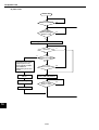
[2] PC scan cycle
In the PC scan cycle, the following three operations (1) to (3) are repeated cyclically.
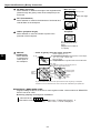
(1) Input refresh
The ON/OFF data from the parallel input terminals (X0 to X7) is written into the data memory (input
relays).
(2) Ladder circuit calculation (final output conditions)
The calculations are executed by the ladder circuit program which contains the data from input
relays, output relays, auxiliary relays (incl. output which are obtained by the ladder circuit program
calculation in the measurement processing cycle), timer and counter.
(3) Output refresh
The ON/OFF data of the output relays, obtained in calculation (2), is output to the parallel output
terminals (Y0 to Y7).
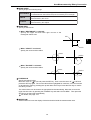
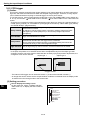
- The processing time for the three steps described above is called "1PC scan time," and ranges
from 0.3 to 3.0 ms, depending on the settings.
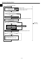
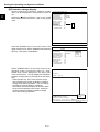
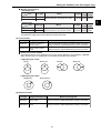
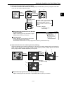
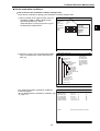
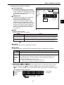
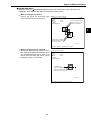
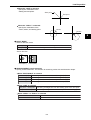
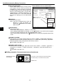
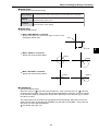
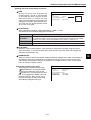
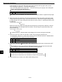
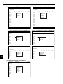
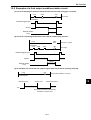
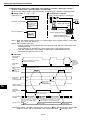
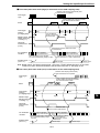
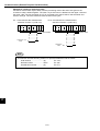
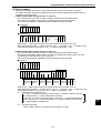
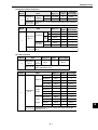
[3] Measurement processing cycle
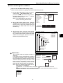
When the measurement start input signal is given, the measurement processing is carried out, and the
calculations of the ladder circuit program for measurements 0 to 3 are executed.
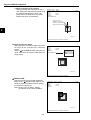
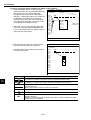
(1) Measurement processing (measurement 0 to 4)
- The coordinates, distance, and degree of match are determined by the measurement programs. If
the numerical calculation conditions have been set, calculations will be executed.
- Each measurement obtained is judged to be OK or NG, based on the criteria entered by the user.
If it is OK, 1 (ON) will be used as the input condition for the following calculation on the ladder
circuit, and if it is NG, 0 (OFF) will be used.
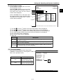
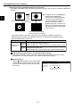
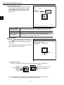
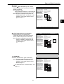
(2) Ladder circuit calculation (based on output conditions for measurements 0 to 4)
- The values obtained from the measurement processing are used as the input conditions for the
ladder circuit. Calculations will be executed by a ladder circuit. The output relays are the auxiliary
relays that will be used for calculation by the ladder circuit in the PC scan cycle.
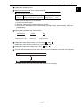
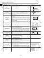
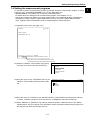
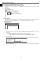
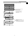
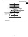
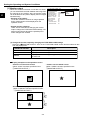
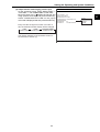
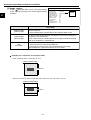
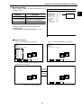
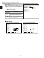
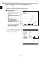
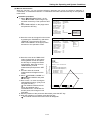
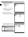
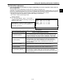
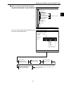
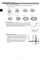
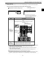
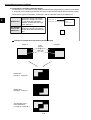
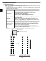
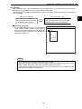
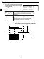
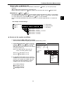
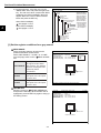
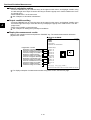
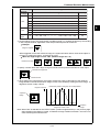
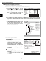
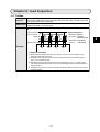
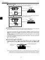
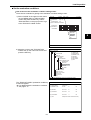
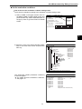
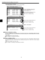
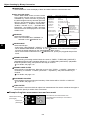
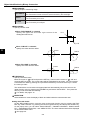
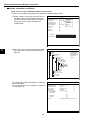
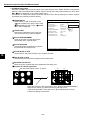
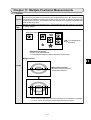
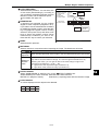
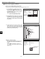
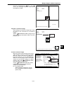
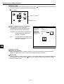
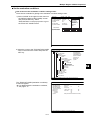
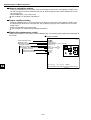
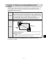
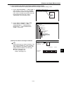
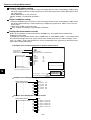
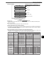
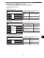
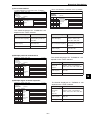
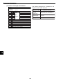
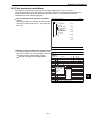
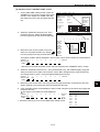
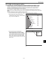
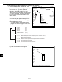
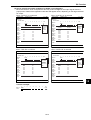
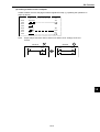
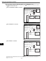
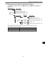
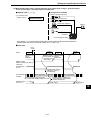
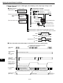
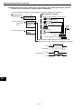
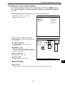
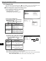
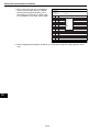
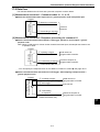
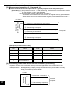
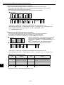
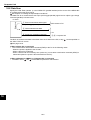
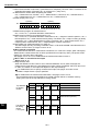
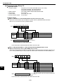
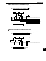
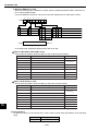
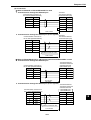
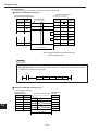
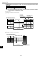
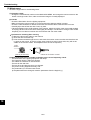
The relationship between the ladder circuit in the measurement processing
cycle and the ladder circuit in the PC scan cycle
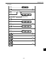
Measurement processing cycle ladder circuit (measurement output conditions)
Measurement 0 - camera 1
Measurement 2
(Positional deviation
Measurement 1
measurement)
(Binary area measurement) (Point measurement)
0M0
15
C000
Degree Auxiliary
of match relay
PC scan cycle
ladder circuit
(final output conditions)
00A
C001
Total Auxiliary
relay
area
C000 C001
P000
C002
Point
Auxiliary
relay
Y00
C002
External
output
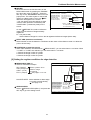
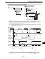
Notes
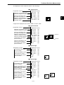
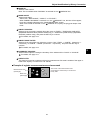
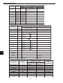
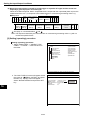
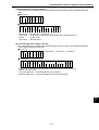
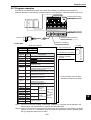
- 128 auxiliary relays, C000 to C127, can be set. However, identical auxiliary relay numbers
cannot be used for measurement 0 using camera 1, and measurement 0 using camera 2, or
for measurement 1, measurement 2, measurement 3 and measurement 4.
- The auxiliary relays C110 to C127 are special relays. The special relays are used on the PC
scan cycle ladder circuit. Do not use them for the measurement processing cycle ladder
circuit.
15-2