1
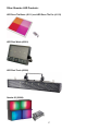
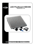
LED Pixelboard 500/256
ORDERCODE 101130
Congratulations!
You have bought a great, innovative product from Showtec.
The Showtec LED Pixelboard brings excitement to any venue.
You can rely on Showtec, for more excellent lighting products.
We design and manufacture professional light equipment for the entertainment industry.
New products are being launched regularly. We work hard to keep you, our customer, satisfied.
For more information: [email protected]
You can get some of the best quality, best priced products on the market from Showtec.
So next time, turn to Showtec for more great lighting equipment.
Always get the best -- with Showtec !
Thank you!
Showtec
Showtec LED Pixelboard™ Product Guide
Warning..…...................................................................................…………………………………………..
Safety-instructions………………………………………………………………………………………….….
Operating Determinations…………………………………………………………………………………….
2
2
3
Description..…..............................................................................……….…………………………………
Features and Overview ………………………………...….……………….………….………………….….
Backside…………………………………………………...…...….……………….…………………...….….
5
5
5
Overall Requirements……….…………………….……………………….……………………….………..…
Computer System Requirements……….……………………….……………………….…………………..
6
6
Set Up and Operation.....................................................................……..……………………………….…
LED Pixelboard Limitations ……………………………………………………………………….……...….
Mounting System to LED Screen Connection……….………………………………………….……...…..
Connecting 96 LED panels to 1 controller..…………………………………………………….……...……
Maximum System Configuration………………………………………….…………………………………
Mounting System Connections………………………………………………………………………………
Attaching the Flying Bracket…………………………………………………………………………………
Dip Switch Settings……………………………………………………………………………………………
JP1 Dipswitches………………………………………………………………………………………………
JP2 Dipswitches………………………………………………………………………………………………
Transmitter Card………………………………………………………………………………………………
Makking an additional Net-cable…………………………………………………………………………….
Transmitter Card Installation…………………………………………………………………………………
Example System Configurations…………………………………………………………………………….
Speacial Applications…………………………………………………………………………………………
6
7
8
9
10
11
12
15
15
16
18
18
19
20
23
Maintenance...................................................................................………..………….…….………………
25
Troubleshooting............................................................................………………….………………….…..
No Light............................................………………….……………………………………………………..
Replacing the Fuse........................................................................…………………….…………………
25
25
25
Product Specifications.................................................................……………….…….…………………..
26
Other Showtec LED Products.................................................……………….…….………………………
27
1
WARNING
FOR YOUR OWN SAFETY, PLEASE READ THIS USER MANUAL CAREFULLY
BEFORE YOUR INITIAL START-UP!
SAFETY INSTRUCTIONS
Every person involved with the installation, operation and maintenance of this device has to:
be qualified
follow the instructions of this manual
CAUTION! Be careful with your operations.
With a dangerous voltage you can suffer
a dangerous electric shock when touching the wires!
Before your initial start-up, please make sure that there is no damage caused by transportation. Should
there be any, consult your dealer and do not use the device.
To maintain perfect condition and to ensure a safe operation, it is absolutely necessary for the user to follow
the safety instructions and warning notes written in this manual.
Please consider that damages caused by manual modifications to the device are not subject to warranty.
This device contains no user-serviceable parts. Refer servicing to qualified technicians only.
IMPORTANT:
The manufacturer will not accept liability for any resulting damages caused by the non-observance of
this manual or any unauthorized modification to the device.
•
•
•
•
•
•
•
•
•
•
•
•
•
•
•
•
•
•
Never let the power-cord come into contact with other cables! Handle the power-cord and all
connections with the mains with particular caution!
Never remove warning or informative labels from the unit.
Do not open the device and do not modify the device.
Do not connect this device to a dimmerpack.
Do not shake the device. Avoid brute force when installing or operating the device.
Never look directly into the light source.
Never leave any cables lying around.
Do not switch the device on and off in short intervals, as this would reduce the lamp’s life.
Never use the device during thunderstorms, unplug the device immediately.
Only use device indoor, avoid contact with water or other liquids.
Avoid flames and do not put close to flammable liquids or gases.
Only operate the device after having familiarized with its functions.
Always allow free air space of at least 50 cm around the unit for ventilation.
Always disconnect power from the mains, when device is not used or before cleaning! Only handle
the power-cord by the plug. Never pull out the plug by tugging the power-cord.
Make sure that the device is not exposed to extreme heat, moisture or dust.
Make sure that the available voltage is not higher than stated on the rear panel.
Make sure that the power-cord is never crimped or damaged. Check the device and the power-cord
from time to time.
The cable insert or the female part in the device must never be strained. There must always be
sufficient cable to the device. Otherwise, the cable may be damaged which may lead to deadly
electrical shocks.
2
•
•
•
•
•
•
•
•
•
•
If the external cable is damaged, it has to be replaced by a qualified technician.
If device is dropped or struck, disconnect mains power supply immediately. Have a qualified
engineer inspect for safety before operating.
If the device has been exposed to drastic temperature fluctuation (e.g. after transportation), do not
switch it on immediately. The arising condensation water might damage your device. Leave the
device switched off until it has reached room temperature.
If your Showtec device fails to work properly, discontinue use immediately. Pack the unit securely
(preferably in the original packing material), and return it to your Showtec dealer for service.
For adult use only. Lighteffect must be installed out of the reach of children. Never leave the unit
running unattended.
The user is responsible for correct positioning and operating of the LED Pixelboard. The
manufacturer will not accept liability for damages caused by the misuse or incorrect installation of
this device.
This device falls under protection class I. Therefore it is essential to connect the yellow/green
conductor to earth.
Repairs, servicing and electric connection must be carried out by a qualified technician.
For replacement use fuses of same type and rating only.
WARRANTY: Till one year after date of purchase.
CAUTION ! EYEDAMAGES !.
Avoid looking directly into the light source.
(meant especially for epileptics) !
OPERATING DETERMINATIONS
This device is not designed for permanent operation. Consistent operation breaks will ensure that the device
will serve you for a long time without defects.
The minimum distance between light-output and the illuminated surface must be more than 0,5 meters.
The maximum ambient temperature ta = 45°C must never be exceeded.
The relative humidity must not exceed 50 % with an ambient temperature of 45° C.
If this device is operated in any other way, than the one described in this manual, the product may suffer
damages and the warranty becomes void.
Any other operation may lead to dangers like short-circuit, burns, electric shock, lamp explosion, crash etc.
You endanger your own safety and the safety of others!
Improper installation can cause serious damage to people and property !
3
Connection with the mains
Connect the device to the mains with the power-plug.
Always pay attention, that the right color cable is connected to the right place.
Cable
Pin
International
BROWN
FASE
L
BLUE
NUL
N
YELLOW/GREEN
EARTH
Make sure that the device is always connected properly to the earth!
4
Description of the device
Features
The LED Pixelboard is a fabulous LED Lighteffect from Showtec.
• Inputs: DVI, VGA, RF, YC, YCbCr, SCART, and HDMI
• 16million colors (24bit)
• Effects: Video/flash/text/RGB color mixing and any PC based graphics
• Play music videos (example Windows Mediaplayer) and DVDs from your computer
• Average Lifespan: 50,000~100,000hrs
• Mounting system has rigging points and flexible configurations
• Additional power-con output for daisy chaining units together
• Additional video output for daisy chaining units together
• Rated Power: 192W
• IP Rating: IP65
• OUTPUT/led: 0.08W
• LED/Unit: 2304pcs
• Cooling: Direct air convection
• LED/Pixel: 3xRED/3XGREEN/3XBLUE
• Pixel/Unit: 16 x 16
• Pixel Pitch: 31mm
• Pixel Density: 1024 pixels/m
Control
• Software: LEDstudio
• System: Windows XP/ATI video card
• Works with other manufacturer’s software Pandora’s Box, Arkaos, Sweetlight Timeline
• Applications: Small or large, interior or exterior architectural/ advertising /stage
Overview
Fig. 1
5
Overall Requirements
• Windows XP computer with an available PCI slot
• ATI graphics card or Nvdia Geforce with DVI Out
• LED Pixelboard Controller (101140); 1 controller for every 6 panels wide and 16 panels high
Computer System Requirements
Minimum
Operating system: Windows XP SP2 (Service Pack 2)
Processor: Pentium 200 MHz with at least one free PCI slot
Harddisk: 20 GB 5400 RPM
Memory: 128 MB
Graphic Card: ATI Graphics Card with dual display and DVI-I output
Note: NVIDIA graphics cards are not compatible with this software
Recommended
Operating system: Windows XP SP2 (Service Pack 2)
Processor: Pentium 1 GHz or better with at least one free PCI slot
Harddisk: 40 GB 7200 RPM or more
Memory: 512 MB or higher
Graphic Card: ATI Graphics Card with dual display and DVI-I output
Note: NVIDIA graphics cards are not compatible with this software
Tested on an ATI Radeon 9300
Set Up and Operation
Before plugging the unit in, always make sure that the power supply matches the product specification
voltage. Do not attempt to operate a 120V specification product on 230V power, or vice versa.
Always disconnect from electric mains power supply before cleaning or servicing.
Damages caused by non-observance are not subject to warranty.
The LED Pixelboard can be used indoors and outdoors. Due to the IP65 rating, the LED Pixelboard will be
reliable and safe to use in most weather conditions. The LED Pixelboard can be viewed during night-time as
well as day-time. Due to the clever mounting system it is easy to setup. The LED Pixelboard excellent
design allows you to vary the setup in many shapes and sizes.
6
LED Pixelboard Limitations
Horizontal Panels (Left/Right)
Minimum 1 Panel
Maximum with 6 panels (1 Controller)
Maximum with 48 panels (2 Controllers)
16 columns of LED clusters or 16 horizontal pixels/lines
96 columns of LED clusters or 96 horizontal pixels/lines
768 columns of LED clusters or 768 horizontal pixels
Vertical Panels (UP/Down)
Minimum 1 Panel
Maximum with 16 panels (1 Controller)
Maximum with 32 panels (2 Controllers)
16 rows of LED clusters or 16 vertical pixels/lines
256 rows of LED clusters or 256 vertical pixels/lines
512 rows of LED clusters or 512 vertical pixels
Resolution
Minimum 1 Panel
Maximum With (1 Controller)
Maximum With (2 Controllers)
16 X 16 Pixels
96 X 128 Pixels
768 X 512 Pixels
1 Panel is 16 pixels on your PC screen.
So 8 x 6 panels (4 x 3 meters) = a resolution of 128 x 96 pixels in Windows XP.
7
1) PCB
2) Power supply
3) Power supply mounting plate
4) Mounting support B
5) Rubber seal
6) Plastic casing
7) Mounting support A
8) Handle
9) Display cover
10) Power connector
11) Cable watertight locking nut
12) Rubber seal
13) Watertight locking nut
14) Rubber seal
15) Watertight locking thread
16) Signal connector
17) PCB
18) Alan bolt
19) Signal connector
20) Mains power connection
21) Mains power connection
22) DC +12V
23) COM
24) GND
25) Neutral
26) Live
Mounting System to LED Screen Connection
Each LED Pixelboard panel is mounted to the mounting system using 4 x M10 Hexagon Bolts.
Note: These bolts only need to be removed when an LED Panel needs to be moved or serviced, when the
mounting system is locked to other units (and it is not possible to unlock the mounting system).
8
Connecting 96 LED panels to 1 controller
9
Maximum System Configuration
Other Setup Possibilities
10
Mounting System Connections
Each LED Pixelboard can be locked to any other panel, using the interlocking connectors at the rear of each
Pixelboard.
Note: Always position the panels using the position guides.
Inter-lock the LED Pixelboards together using the thumb-bolts.
Always check that the thumb-bolts are tightly fastened using a spanner.
11
Attaching the Flying Bracket
The flying bracket attachment is used to rig a 1 meter section (Width) of the LED Pixelboard. It is designed
to be attached to the very top row of a 1 meter section. Additional hardware is provided for interconnecting
multiple flying brackets.
Note:
Always make sure that all bolts are securely fastened.
For screens measuring 3 meters in height or beyond, use 2 rigging points for every 1 meter section.
Do not use on systems larger than 6 meters in height.
12
13
14
Dip switch settings
A LED Pixelboard video display matrix may consist of up to 16 controllers or 16 individual grid sections in
various pattern configurations. Each controller must be addressed according to your configuration so that
the video appears whole and intact. Two internal dipswitches (JP1 & JP2) are addressed according to your
system layout and configuration.
Open the controller to change the Dipswitch settings.
1 Panel is 16 pixels on your PC screen.
So 8 x 6 panels ( 4 x 3 meters) = a resolution of 128 x 96 pixels in Windows XP.
JP1:
Sets the total width one driver will display. The width can be described in either number of panels or pixel
resolution. Possible widths include 1 to 6 panels or 16 to 96 horizontal pixels
JP2:
Sets the starting vertical line from which this driver will begin to display video. Remember that a matrix may
consist of multiple sections across, so in order to display video correctly you will need to set starting
address for each section handled by a driver.
JP1 Dipswitches
JP1 dipswitches have their own unique addressing method. For example setting dipswitch 3 to ON adds 32
values to the counter while setting 11 to ON subtracts 16.
15
JP2 Dipswitches
In order for video to display properly across multiple sections or drivers, each driver must be addressed
accordingly. The JP2 dipswitch establishes the horizontal starting address or (vertical line) for each section
of matrix.
Just like the JP1 dipswitch, JP2 has different numerical designations for addressing.
Dipswitches 6 and 7 always remain in the ON position.
16
You can use the table below to quickly identify the dipswitch settings for your matrix width.
17
Transmitter Card
Install the transmitter card in an available PCI slot in your computer. The transmitter card is the interface
between your PC, LED Studio and the LED Pixelboard. You must use the DVI cable provided to connect
from the computers DVI output to the DVI port on the transmitter card.
Data Out 1 & Data Out 2 connectors
The 2 network output ports transmit 256 rows or horizontal lines. Output 1 transmits rows/lines 1 throug 256.
output 2 transmits rows/lines 257 through 512.
Aux Port
This is a standard 6-pin telephone connector. A cable is provided that connects from the 9-pin dIN R-232
port to the AUX port on the transmitter card. This port allows control of the R variable, gray scale, DV Wall
matrix active area, and matrix lock and matrix range.
DC External Power Input
This input takes the 5V power supply provided. It is only used if the transmitter card will be operated
eternally of the computer.
Making an additional Net-cable
Standard NET CABLE cannot be used to replace the NET CABLE required to transmit the information for
the LED MATRIX system.
Please follow the following instructions in order to create extra NET CABLE.
Bear back the outer casing of the wire by around 30mm
The wires should now be colored as follows:
1- white & orange
2- orange
3- white & green
4- green
5- blue
6- white & blue
7- white & brown
8- brown
Twist the following pairs together so that only the plastic is touching (the metal wires must not touch) 1&2,
3&4, 5&6, 7&8
Insert each wire into an RJ45 connector with the white & orange wire connected to PIN 1, the orange wire
connected to the second PIN, etc.
Both ends of the NET WIRE are connected in this way.
18
Transmitter card installation
1) Turn off your computer and disconnect from the powersource. Always take these precautions before
opening the case and adding/removing components.
2) Insert the transmitter card into an available PCI slot in your computer.
3) Connect the DVI output from your computer’s display card to the DVI input on the transmitter card, using
the DVI signal cable provided.
4) Connect your computer’s serial RS232 (also known as COM port) connector to the 6-pin telephone
connector of the transmitter card, using the RS232 signal cable provided.
5) Connect the RJ45 OUT 1 connector to the controller’s Net IN connector with the provided net cable to
display rows 1 through 256.
6) When you want to display 512 row lines, connect the OUT 2 to a second controller.
7) Make sure that all connections are correctly connected, before applying power to the entire system.
8) In order to test the system successfully, it will be necessary to address the controllers correctly.
Also see page 15 for the controllers dipswitch settings.
9) Once the controllers are assigned, turn on the computer and test the system.
Warning
When your PC starts up and your screen stays black after connecting the transmitter card, turn off your
computer immediately and disconnect the DVI cable from the transmitter card. Reboot your PC and when
Windows has loaded, reconnect the DVI cable.
19
Example System Configurations
20
21
22
Special Applications
23
24
Maintenance
The operator has to make sure that safety-relating and machine-technical installations are to be inspected
by an expert after every four years in the course of an acceptance test.
The operator has to make sure that safety-relating and machine-technical installations are to be inspected
by a skilled person once a year.
The following points have to be considered during the inspection:
1. All screws used for installing the device or parts of the device have to be tightly connected and must
not be corroded.
2. There may not be any deformations on housings, fixations and installation spots.
3. Mechanically moving parts like axles, eyes and others may not show any traces of wearing.
4. The electric power supply cables must not show any damages or material fatigue.
The Showtec LED Pixelboard requires almost no maintenance. However, you should keep the unit clean.
Otherwise, the fixture’s light-output will be significantly reduced. Disconnect the mains power supply, and
then wipe the cover with a damp cloth. Do not immerse in liquid. Wipe lens clean with glass cleaner and a
soft cloth. Do not use alcohol or solvents. Keep connections clean. Disconnect electric power, and then wipe
the connections with a damp cloth. Make sure connections are thoroughly dry before linking equipment or
supplying electric power.
Troubleshooting
This troubleshooting guide is meant to help solve simple problems.
If a problem occurs, carry out the steps below in sequence until a solution is found. Once the unit operates
properly, do not carry out following steps.
1. If the device does not operate properly, unplug the device.
2. Check the fuse, power from the wall, all cables etc.
3. If all of the above appears to be O.K., plug the unit in again.
4. If you are unable to determine the cause of the problem, do not open the LED Pixelboard, as this may
damage the unit and the warranty will become void.
5. Return the device to your Showtec dealer.
No Light
This troubleshooting guide is meant to help solve simple problems. If a problem occurs, carry out the steps
below in sequence until a solution is found. Once the unit operates properly, do not carry out following
steps.
If the light effect does not operate properly, refer servicing to a technician.
Response: Suspect three potential problem areas: the power supply, the LEDs or the fuse.
1. Power supply. Check that the unit is plugged into an appropriate power supply.
2. The LEDs. Return the LED Pixelboard to your Showtec dealer.
3. The fuse. Replace the fuse.
Replacing the Fuse
Power surges, short-circuit or inappropriate electrical power supply may cause a fuse to burn out. If the fuse
burns out, the product will not function whatsoever. If this happens, follow the directions below to do so.
1. Unplug the unit from electric power source.
2. Insert a screwdriver into the slot in the fuse cover. Turn the screwdriver to the left, at the same time gently
push a bit (Turn and Push). The fuse will come out.
3. Remove the used fuse. If brown or unclear, it is burned out.
4. Insert the replacement fuse into the holder where the old fuse was. Reinsert the fuse cover. Be sure to
use a fuse of the same type and specification. See the product specification label for details.
25
Product Specification
Model: Showtec LED Pixelboard
Gray Scale: Red/Green/Blue 256 grade(8 BIT)
Colors: 256 x 256 x 256 = 16M Colors
Supports Display: 640 X 480 / 800 X 600 / 1024 X 768
Supports Display Card: DVI Connector Display Card
Interface Cards (1 set): Data Collection Card 1pcs
Range: 768 X 512
Dimmer: Hardware 16 grade,Software 256 grade
Frequency: 16Mhz 12Mhz 8Mhz 6Mhz(Adjustable)
Sweeping Frequency: >90HZ
Scan mode: 16 rows/area
Output Port: 2x50
Signal Cable: 5-core Net Cable
Maximum Signal Transmission Distance: High Speed>100m(no breaks)
Common Power: +5V
Dimensions: 406x254x228mm (LxWxH)
Weight: 5,79 kg
LAMPS: ELC3 (24V 250W)
PHOTO OPTIC
Beam Angle: 11°
Pan: 510°
Tilt: 260°
Illuminance: (2,330fc or 25,070lux) @ 1 meter
FUSE:
Main 20mm Glass 7A Fast Blow
CONTROL & PROGRAMMING
Data input: locking 3-pin XLR male socket
Data output: locking 3-pin XLR female socket
Data pin configuration: pin 1 shield, pin 2 (-), pin 3 (+)
Protocols: DMX-512 USITT
DMX Channels: 7
Design and product specifications are subject to change without prior notice.
Website: www.Highlite.nl
Email: [email protected]
26
Other Showtec LED Products:
LED Deco-Tile Basic (41111) and LED Deco-Tile Pro (41112)
LED Pixel Wash (42201)
LED Pixel Track (42200)
Quadra 20 (30984)
27
Octopod 30 (30985)
Trackpod 30 (30986)
Octopod 90 (30987)
Trackpod 90 (30988)
28
Riva 90 (30989)
LED Panel (41070)
LED Wallpainter (41200)
Aquapainter (41220)
29