1
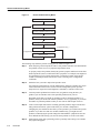
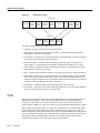
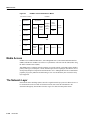
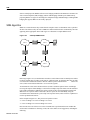
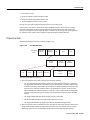
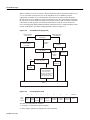
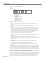
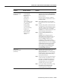
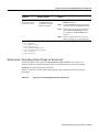
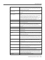
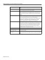
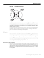
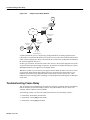
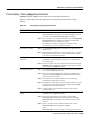
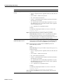
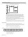
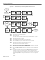
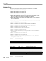
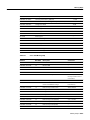
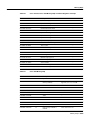
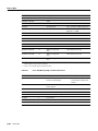
Troubleshooting Hardware
Possible Problem
Solution
Disk assembly problems
Disk assembly problems are indicated by the following symptoms:
• The node fails to boot.
• Files become corrupted.
• In a system with two NPs, the primary NP appears to fail and the backup
takes over. The failed NP might pass diagnostics.
• The system fails to read or write floppy disks. In the case of a write
failure, check the write protect switch on the disk.
If a disk problem is indicated, check the disk assembly connector for bent or
broken pins. If any pins are bent or damaged, they are the likely source of
the problem. Replace the disk assembly connector.
If the connector is in good condition, the problem may be in the disk
assembly itself, or in the software on the disk. If you suspect a problem with
the software, you should be able to correct it by reinstalling the software as
described in the LightStream 2020 Network Operations Guide.
Midplane problems
Midplane problems are indicated by the following symptoms:
• A card fails in one slot but operates normally in other slots.
• Data transmission problems do not go away when you replace the FRU8
that appears to be failing, or problems occur in several FRUs
simultaneously. (Problems of this type might also indicate a faulty switch
card.)
• Failure of a card to fully insert into its slot. This probably indicates
damage to the connectors on either the card or the midplane. Inspect all
the connectors and replace the card or the midplane if you find damage.
• Electrical failure or electrical problems that do not go away when you
replace the FRU that appears to be failing, or that occur in several FRUs
simultaneously. Electrical problems include out-of-range voltages.
1
2
3
4
5
6
7
8
CLI = command-line interface
POST = power-on self-test
FLT = fault
TCS = test and control system
NP = network processor
NPAC = network processor access card
FDDI = Fiber Distributed Data Interface
FRU = field-replaceable unit
Testing and Verifying Replacement Parts
If you are replacing a part or card to remedy a suspected problem, make only one change at a time.
To test a system, start with a simple hardware configuration and add one card at a time until a failed
interface appears or is isolated. Use a simple software configuration and test connectivity using a
ping test.
If you determine that a part or card replacement is required, contact your sales or technical support
representative. Specific instructions concerning part or card installation are outlined in the
configuration note provided with the replacement.
For modular routers, make sure that you seat all cards correctly. Check the seating of cards if the
system is not booting properly. Use the ejector levers to reseat all processor modules, and then
reboot.
3-40
Book Title