1
Installation
3
Testing the Installation
Devices connected to the eLAN or Elite Panel must be allocated addresses so that the control panel can identify the
integrity of the circuit path. The address switch should never be set with all switches in the off position.
Provide an address on the switch by setting a binary number from 1 to 15 on the 4 way, DIP switch located at the bottom of the PCB. The order of the addresses is not important but each device must be allocated a different address.
The switch settings for each of the addresses are shown below.
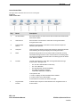
Figure 3-5 illustrates binary addresses 1 to 15 on the eView:
Figure 3-5
Binary Addresses
The black portion of the DIP identifies the switch actuator. An address of 7 is set when actuators of the DIP switch are
“up” on positions 1, 2 and 3.
These settings identify:
•
20 for switch position 1, where 20 = 1
•
21 for switch position 2, where 21 = 2
• 22 for switch position 3, where 22 = 4
The binary address for this DIP is 1 + 2 + 4 = 7
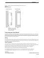
Figure 3-6 illustrates settings for an address of 7 on the DIP switch of the eView:
Figure 3-6
DIP Switch Settings
ON
1
2
3
4
The arrow in the figure above identifies the on position of the DIP when the switch actuator is in the “up” position.
VES, LLC
eView Installation Manual
VF3510-00, Revision E01.06
14 of 16