1
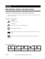
Smart-UPS® VT 10-40kVA 400V Operation Manual Smart-UPS® VT 10-40kVA 400V Operation Manual ! Output Pwr Zone Probe 10/100Ba Reset se-T AP9619 10/100 Network Managem ent Card EM IMPORTANT! THIS DOCUMENT CONTAINS IMPORTANT SAFETY INSTRUCTIONS – PLEASE SAVE THESE INSTRUCTIONS! Smart-UPS® VT and XR Battery Enclosure 10-40kVA, 400V Operation Manual – 990-1985 1 Contents Safety .....................................................................1 IMPORTANT SAFETY INSTRUCTIONS . . . . . . . . . . . . . . . . . . . . . 1 IMPORTANT SAFETY INSTRUCTIONS – SAVE THESE INSTRUCTIONS . . . . . . . . . . . . . . . . . . . . . . . . . . . 1 Symbols used in this guide . . . . . . . . . . . . . . . . . . . . . . . . . . . . 1 Environmental symbols . . . . . . . . . . . . . . . . . . . . . . . . . . . . . . . 1 General safety symbols . . . . . . . . . . . . . . . . . . . . . . . . . . . . . . . 2 Operation ...............................................................3 Introduction . . . . . . . . . . . . . . . . . . . . . . . . . . . . . . . . . . . . . . . 3 The Smart-UPS VT Family Range . . . . . . . . . . . . . . . . . . . . . . . . 5 352mm Enclosures –10-20kVA . . . . . . . . . . . . . . . . . . . . . . . . . 5 523mm Enclosures – 30-40kVA . . . . . . . . . . . . . . . . . . . . . . . . . 5 Serial number . . . . . . . . . . . . . . . . . . . . . . . . . . . . . . . . . . . . . . 6 Type label . . . . . . . . . . . . . . . . . . . . . . . . . . . . . . . . . . . . . . . . . 6 Operation Modes . . . . . . . . . . . . . . . . . . . . . . . . . . . . . . . . . . . 7 Normal operation . . . . . . . . . . . . . . . . . . . . . . . . . . . . . . . . . . . 7 Battery operation . . . . . . . . . . . . . . . . . . . . . . . . . . . . . . . . . . . 7 Bypass operation (or static bypass operation) . . . . . . . . . . . . . . 7 Mechanical bypass . . . . . . . . . . . . . . . . . . . . . . . . . . . . . . . . . . 7 Wrap -around maintenance bypass . . . . . . . . . . . . . . . . . . . . . . 8 The Display . . . . . . . . . . . . . . . . . . . . . . . . . . . . . . . . . . . . . . . 9 Introduction . . . . . . . . . . . . . . . . . . . . . . . . . . . . . . . . . . . . . . . 9 990-2282 Smart-UPS® VT 10-40kVA, 400V, Operation Manual i Navigation . . . . . . . . . . . . . . . . . . . . . . . . . . . . . . . . . . . . . . . 10 Menu-driven user functions . . . . . . . . . . . . . . . . . . . . . . . . . . . 10 Basic display navigation principles . . . . . . . . . . . . . . . . . . . . . . 11 Control functions . . . . . . . . . . . . . . . . . . . . . . . . . . . . . . . . . . . 11 Status views . . . . . . . . . . . . . . . . . . . . . . . . . . . . . . . . . . . . . . 12 Clock set-up . . . . . . . . . . . . . . . . . . . . . . . . . . . . . . . . . . . . . . . 13 Logging . . . . . . . . . . . . . . . . . . . . . . . . . . . . . . . . . . . . . . . . . 14 Alarm threshold . . . . . . . . . . . . . . . . . . . . . . . . . . . . . . . . . . . . 15 Display setup . . . . . . . . . . . . . . . . . . . . . . . . . . . . . . . . . . . . . . 15 Diagnostics screen . . . . . . . . . . . . . . . . . . . . . . . . . . . . . . . . . . 16 Front Panel Removal/Installation . . . . . . . . . . . . . . . . . . . . . . 17 Front Panel removal . . . . . . . . . . . . . . . . . . . . . . . . . . . . . . . . 17 Front Panel installation . . . . . . . . . . . . . . . . . . . . . . . . . . . . . . 17 Network Management Card with Environmental Monitor . . . . . 18 Network Management Card replacement . . . . . . . . . . . . . . . . . 18 Part number . . . . . . . . . . . . . . . . . . . . . . . . . . . . . . . . . . . . . . 18 Display Messages/Troubleshooting . . . . . . . . . . . . . . . . . . . . . 19 Display messages . . . . . . . . . . . . . . . . . . . . . . . . . . . . . . . . . . . 19 Total-Power-Off Procedure . . . . . . . . . . . . . . . . . . . . . . . . . . . 22 Restart procedure . . . . . . . . . . . . . . . . . . . . . . . . . . . . . . . . . . 23 Power application . . . . . . . . . . . . . . . . . . . . . . . . . . . . . . . . . . 23 Voltage confirmation . . . . . . . . . . . . . . . . . . . . . . . . . . . . . . . . 24 Mechanical Bypass . . . . . . . . . . . . . . . . . . . . . . . . . . . . . . . . . 25 Mechanical Bypass Lever . . . . . . . . . . . . . . . . . . . . . . . . . . . . . 25 Switch into mechanical bypass . . . . . . . . . . . . . . . . . . . . . . . . . 25 Switch into normal operation (from mechanical bypass operation) . . . . . . . . . . . . . . . . . . . . . . . . . . . . . . . . . . 27 ii Smart-UPS® VT 10-40kVA, 400V, Operation Manual 990-2282 Warranty ..............................................................28 LIMITED FACTORY WARRANTY . . . . . . . . . . . . . . . . . . . . . . . . 28 APC product covered . . . . . . . . . . . . . . . . . . . . . . . . . . . . . . . . 28 Terms of warranty . . . . . . . . . . . . . . . . . . . . . . . . . . . . . . . . . . 28 Non-transferable warranty extends to first purchaser for use . . 28 Assignment of warranties . . . . . . . . . . . . . . . . . . . . . . . . . . . . 29 Drawings, descriptions . . . . . . . . . . . . . . . . . . . . . . . . . . . . . . 29 Warranty claims procedure . . . . . . . . . . . . . . . . . . . . . . . . . . . 29 Exclusions . . . . . . . . . . . . . . . . . . . . . . . . . . . . . . . . . . . . . . . . 29 Life Support Policy . . . . . . . . . . . . . . . . . . . . . . . . . . . . . . . . . 30 Appendix ..............................................................31 UPS Components and Options . . . . . . . . . . . . . . . . . . . . . . . . 31 352mm Enclosures –10-20kVA . . . . . . . . . . . . . . . . . . . . . . . . 31 523mm Enclosures – 30-40kVA . . . . . . . . . . . . . . . . . . . . . . . . 31 UPS sizes and weights . . . . . . . . . . . . . . . . . . . . . . . . . . . . . . . 32 User interface . . . . . . . . . . . . . . . . . . . . . . . . . . . . . . . . . . . . . 33 APC Network Management Card AP9619 (installed in UPS) and APC Humidity Sensor (Optional) . . . . . . . . . . . . . . . . . . . . 34 APC Smart-UPS VT Battery Temperature Sensor (Optional) 1 delivered with UPS . . . . . . . . . . . . . . . . . . . . . . . . . . . . . . . . . 34 Floor anchoring (Optional) . . . . . . . . . . . . . . . . . . . . . . . . . . . 35 Options . . . . . . . . . . . . . . . . . . . . . . . . . . . . . . . . . . . . . . . . . 36 Maintenance Bypass Panels . . . . . . . . . . . . . . . . . . . . . . . . . . . 36 APC Smart-UPS VT 10-40kVA Battery Breaker Box . . . . . . . . . . 37 Customized Battery solutions . . . . . . . . . . . . . . . . . . . . . . . . . 37 Smart-UPS® VT Extended Run Battery Enclosure (XR Enclosure) and Battery Module . . . . . . . . . . . . . . . . . . . . . 37 990-2282 Smart-UPS® VT 10-40kVA, 400V, Operation Manual iii Safety IMPORTANT SAFETY INSTRUCTIONS IMPORTANT SAFETY INSTRUCTIONS – SAVE THESE INSTRUCTIONS This guide contains important instructions that should be followed when handling the UPS, Battery Enclosures, and Batteries. Symbols used in this guide WARNING! Risk of electric shock. CAUTION! Read this information to avoid equipment damage. Indicates important information. Note Indicates that more information is available on this subject in a different section of this manual. Indicates that more information is available on the same subject in a different manual. Environmental symbols Temperature 990-2282 Ventilation requirements Humidity Dust/Fumes Smart-UPS® VT 10-40kVA, 400V, Operation Manual Altitude 1 Safety – IMPORTANT SAFETY INSTRUCTIONS General safety symbols Two people to lift a component weighing between 18 - 32 kg. For configurations including customer-supplied external batteries, refer to manufacturer’s battery installation and maintenance instructions. 2 Smart-UPS® VT 10-40kVA, 400V, Operation Manual 990-2282 Operation Introduction Welcome to the Operation Manual covering the Smart-UPS® VT. This manual provides you with a detailed description of start-up, operation, and troubleshooting. Separate manuals are available on: • Receiving and Unpacking part no. 990-2284 • Site preparation and Installation part no. 990-2283. ! Output Pwr Zone Probe 10/100Ba Reset se-T AP9619 10/100 Network Managem ent Card EM For documentation on Maintenance Bypass Panels and APC Smart-UPS VT 10-40kVA Battery Breaker Box, see product-specific manuals. For more details on APC products and services, visit us at www.apc.com Note Note APC recommends that you request a wiring diagram from the electrician after completed electrical installation. A wiring diagram is useful for subsequent service and troubleshooting. WARNING! Only trained personnel familiar with the construction and operation of the equipment, including the electrical and mechanical hazards involved, may install and remove system components. 990-2282 Smart-UPS® VT 10-40kVA, 400V, Operation Manual 3 Operation – Introduction Details on the UPS sizes, weight etc. are available in the Appendix under “UPS sizes and weights” on page 36. Note Most illustrations show 523mm Enclosures but apply to both Enclosure sizes. Any differences between the two Enclosure sizes will be addressed in the manual. Note 4 Smart-UPS® VT 10-40kVA, 400V, Operation Manual 990-2282 The Smart-UPS VT Family Range 352mm Enclosures –10-20kVA ! Output Pwr Zone Probe 10/100BaseT Reset AP9619 10/100 Network Managemen t Card Rear Front EM Front view without front panel Type label 523mm Enclosures – 30-40kVA ! Output Pwr Zone Probe ! Output 10/100Ba Reset Pwr se-T Zone Probe AP9619 10/100Ba Reset 10/100 Network Managem se-T ent Card EM AP9619 10/100 Network Managem ent Card Front 990-2282 Type label Rear EM Front view without front panel Smart-UPS® VT 10-40kVA, 400V, Operation Manual 5 Operation – The Smart-UPS VT Family Range Serial number The serial number is available on the type label placed on the rear side of the UPS. Type label Hotline in US/Canada/LAM: +1 800 800 4APC ¥ Hotline in EMEA: +353 91 70 2000 ¥ Worldwide Support numbers: www.apcc.com/support/contact/ Mark acc. to SKU No. APC SKU SUVT10KH SUVT15KH SUVT20KH SUVT30KH SUVT40KH APC SKU w.startup SUVT10KHS SUVT15KHS SUVT20KHS SUVT30KHS SUVT40KHS Model APC Smart-UPS VT 10kVA 400V APC Smart-UPS VT 15kVA 400V APC Smart-UPS VT 20kVA 400V APC Smart-UPS VT 30kVA 400V APC Smart-UPS VT 40kVA 400V Apparent/Active Power 10kVA/8kW 15kVA/12kW 20kVA/16kW 30kVA/24kW 40kVA/32kW Voltage & Connection Types Unit serial number AC Input 380Y/220V 4W+GND 50/60Hz 400Y/230V 4W+GND 50/60Hz 415Y/240V 4W+GND 50/60Hz AC Output 380Y/220V 4W+GND 50/60Hz 400Y/230V 4W+GND 50/60Hz 415Y/240V 4W+GND 50/60Hz DC Input +/- 192V Rated Input Current 14.4/13.6/13.1A, 380/400/415V 21.5/20.5/19.7A, 380/400/415V 28.7/27.2/26.3A, 380/400/415V 43.1/40.9/39.4A, 380/400/415V 57.4/54.6/52.6A, 380/400/415V Rated Output Current 15.2/14.4/13.9A, 380/400/415V 22.8/21.7/20.9A, 380/400/415V 30.4/28.9/27.8A,380/400/415V 45.6/43.3/41.7A, 380/400/415V 60.8/57.7/55.6A, 380/400/415V SEE INSTALLATION INSTRUCTIONS BEFORE CONNECTING TO THE SUPPLY Battery Current 27.5A 41.2A 55.0A 82.5A 109.9A THIS REAR COVER MUST BE PLACED ON UPS 885-2532_rev01 Write serial number of your UPS here: ______________________________________________ 6 Smart-UPS® VT 10-40kVA, 400V, Operation Manual 990-2282 Operation Modes In a stand-alone installation, the UPS has four different operation modes. If the installation includes a Maintenance Bypass Panel test mode will also be available. Normal operation During normal operation, the UPS converts mains power to conditioned power for the connected load. Battery operation During battery operation, the UPS provides power to the connected load from its batteries for a finite period. The UPS transfers to battery operation if the supply of mains power fails, or is outside predefined limits. Bypass operation (or static bypass operation) Static bypass operation can either be obtained by user request or automatically, as the UPS will switch into bypass operation if both the normal and battery operation modes are unavailable. During static bypass operation, the mains power is sent through internal Radio Frequency Interference (RFI) filters to the connected load, bypassing the internal power converters. The UPS transfers to bypass operation following a command received via the display, or after a short or heavy overload on the output of the UPS. Battery back-up is not available in bypass operation. Mechanical bypass In mechanical bypass, mains power is sent directly to the connected load through a mechanical breaker, bypassing all internal UPS functions and filters. Mechanical bypass is obtained by the operation of the mechanical bypass breaker lever located behind the front cover. Mechanical bypass is a feature designed to keep the load supplied with mains power during maintenance of the UPS power sections. All major maintenance operations can be performed with the UPS running in mechanical bypass, and with the load being supplied directly with unconditioned mains power. 990-2282 Smart-UPS® VT 10-40kVA, 400V, Operation Manual 7 Operation – Operation Modes Wrap -around maintenance bypass The UPS can be connected to an external Maintenance Bypass Panel. When activated, this panel bypasses the entire UPS Enclosure (only possible with an optional APC Maintenance Bypass Panel), feeding mains power directly to the load. An activated wrap-around Maintenance Bypass Panel completely isolates the UPS and allows all kinds of maintenance to be performed – including a replacement of the entire UPS. 8 Smart-UPS® VT 10-40kVA, 400V, Operation Manual 990-2282 The Display Introduction CAUTION! The display provides access to more functions than described in this manual. In order to avoid unwanted load impacts these functions should not be accessed without the assistance of APC Customer Support. For APC Worldwide Customer Support, refer to rear cover of this manual. Four Light Emitting Diode (LED) indicators report the operational status of the UPS. Liquid Cystal Display (LCD) Screen Five navigation keys are used to select and open menu items, to access information, change system parameters, and to launch context-sensitive help. LOAD ON ON BATT BYPASS ESC Chrg 100% Load 000% 230Vin 000Vout 50Hz Runtime: 00hr 30m ? FAULT LOAD ON When the green LED is on, the UPS provides power to the load equipment. ON BATT When the yellow LED is on, power to the load flows from the batteries to the Power Module. BYPASS When the yellow LED is on, power to the load is supplied through the static bypass switch or mechanical bypass. FAULT When the red LED is on, a fault condition exists. LCD Screen Displays alarms, status data, instructional help, and configuration items. UP and DOWN navigation keys Selects menu items and accesses information. HELP key Launches context-sensitive help. ENTER key Opens menu items and input changes to system parameters. ESC key Returns to previous screen displayed. 990-2282 Smart-UPS® VT 10-40kVA, 400V, Operation Manual 9 Navigation Menu-driven user functions If you get beyond the functions described in the menu tree, do not proceed. Press ESC to go back. Control Turn load off UPS into bypass Status Vin Vbyp Vout Iin lbyp Iout kVA & kW Frequencies Load & Bat Overview Main Menu Batteries Chrg xxx% Load xxx% xxxVin Runtime Control Status Setup Logging Display Diags Help Alarm thresholds Clock Setup Settings View log Logging Logging View statistics Display Display setup Beeper setup Diags Diagnostics Faults and Diagnostics 10 Smart-UPS® VT 10-40kVA, 400V, Operation Manual 990-2282 Operation – Navigation Basic display navigation principles On the display, press ESC until you get to the Overview Screen, which provides you with basic system status information. Press UP, DOWN arrows to navigate with the selector arrow and view all sub-menu screens. Chrg 100% Load 000% 230Vin 000Vout 50Hz Runtime: 0hr 0m Overview Screen Press ENTER to open the Main Menu screen. From here, you command, configure, and monitor the system. Control Status Setup Logging Display Diags Help Main Menu Control functions From the Control Screen on the Main Menu, you can select the following functions: 1. Turn Load OFF/ON 2. Switch the UPS into Bypass/out of Bypass Control Status Setup Logging Display Diags Help Main Menu WARNING! Disconnecting the UPS output to the load does NOT de-energize the UPS! Always follow the Total-Power-OFF procedure if you need to de-energize the UPS in emergency situations! Switch load OFF (disconnect the UPS output to the load equipment). 1. From the Main Menu, select Control and press ENTER 2. Use UP/DOWN key to navigate to Turn Load OFF, and press ENTER 3. Select YES, Turn Load OFF 990-2282 Smart-UPS® VT 10-40kVA, 400V, Operation Manual 11 Operation – Navigation Switch load ON. 1. From the Main Menu, select Control and press ENTER 2. Use UP/DOWN key to navigate to Turn Load ON, and press ENTER 3. Select YES, Turn Load ON Switch into bypass. 1. From the Main Menu, select Control and press ENTER 2. Use UP/DOWN key to navigate to UPS into bypass and press ENTER 3. Use UP/DOWN key to navigate to YES, UPS into bypass, and press ENTER Switch out of bypass. 1. From the Main Menu, select Control and press ENTER 2. Select UPS out of Bypass and press ENTER 3. Use UP/DOWN key to navigate to YES, UPS out of Byp, and press ENTER Status views Select Status on the Main Menu to view the status of the following parameters Control Status Setup Logging Display Diags Help Main Menu Voltage on all phases. Mains voltage (V), bypass voltage (V), and output voltage (V) for each phase. Current on all phases. Mains current (A), bypass current (A), and output current (A) for each phase. kVA and kW. Apparent power (kVA) and real power (kW) generated by the UPS to the load. Frequencies. Mains frequency, bypass frequency and output frequency in Hertz (Hz). 12 Smart-UPS® VT 10-40kVA, 400V, Operation Manual 990-2282 Operation – Navigation Load and batteries. Load: Percentage of the load in relation to the total UPS capacity. Bat Voltage: Shows either the positive or negative half of the battery voltage (the lower value of the two will appear). Bat Cap: Percentage charge on the batteries in relation to the total battery capacity. Runtime: The predicted runtime at the current load. Batteries. Bat AmpHr: Battery capacity, including both external and internal batteries. UPS Temp: The highest external battery temperature. Alarm thresholds. Load: An alarm will be set when the load is above the threshold level. Runtime: An alarm will be set when the runtime is below the threshold level. Clock set-up From the Setup screen on the Main Menu, you can change the date and the clock setting. From the Settings screen, select Clock, and press ENTER. A date and a time line will appear. Control Status Setup Logging Display Diags Help Main Menu Time. The clock function is used to time-stamp events in the event log. To avoid inaccuracies, change the clock-setting at e.g. daylight-saving time. Date 1. To change the date, press ENTER (the day field will become active). Press the UP/DOWN arrow to select the desired date. 2. To change the month and the year, follow the same procedures. 3. Press ENTER to confirm the new settings, or ESC to cancel. Time 1. To change the time, press ENTER (the hour field will become active). Press the UP/DOWN arrow to select the desired time. 2. Follow the same procedure to change the minute and the second fields. 3. Press ENTER to save, or ESC to cancel. Press ESC to return to the Main Menu. 990-2282 Smart-UPS® VT 10-40kVA, 400V, Operation Manual 13 Operation – Navigation Logging From the logging screen on the Main Menu, you can view the 100 most recent UPS log events, and view the logged details of the events, such as date and time of occurrence, and event number. Control Status Setup Logging Display Diags Help Main Menu 1. From the Main Menu, select Logging 2. Select View Log 3. Press ESC to return to Main Menu Example: 24-Sep 15:06:48 #15 Mains out of Range On Line =================== Logging Screen (example) The top line indicates date, time and event number. Lines 2, 3 and 4 are part of the event list. To view the entire list, use UP/DOWN arrows to navigate. For a detailed description of a particular event, position the arrow, and press ENTER. View statistics (submenu under Logging). From the Logging screen on the Main Menu, you can view the statistics on operation mode changes, inverter time, duration of battery operation. Control Status Setup Logging Display Diags Help Main Menu 1. From the Main Menu, select Logging 2. Select View Statistics 3. Press ESC to return to Main Menu 14 Smart-UPS® VT 10-40kVA, 400V, Operation Manual 990-2282 Operation – Navigation Alarm threshold If the load level exceeds the preprogrammed threshold, the UPS will display a warning. Example: Alarm Thresholds Load: 20.0 kVA Runtime: 0 hr 0 min Alarm Threshold Screen To change the Alarm Thresholds: 1. Select Setup from the Main Menu 2. Select Alarms from the Setup Menu 3. Press ESC to return to the Main Menu Display setup From the Display Setup screen, you can select your display Language, Contrast, and Beeper functions. Display setup Language: English Contrast: 0 Beeper Setup Display Setup Menu Language selection. From the Main Menu, select Display Setup. To change the language, select Language, and press ENTER. The Language line is now active. Use the UP/DOWN arrows to select the desired language. Press ENTER to confirm your selection. Contrast setting. From the Display Setup Menu, select Contrast, and press ENTER. Use the UP/DOWN arrows to select the contrast level - the lower the number, the darker the contrast. Select ENTER to confirm the setting. Beeper setup. Beeper setup Beep at: PwrFail+30 Vol: Low Key Click: Off Beeper Setup Menu 990-2282 Smart-UPS® VT 10-40kVA, 400V, Operation Manual 15 Operation – Navigation From the Beeper Setup Menu, select Beeper Setup. To change the beeper setup, select Beep at and press ENTER. You now have the following options: • Never: If you select this setting, the Beeper will be active at internal UPS errors only. • PwrFail+30: If you select this setting, the Beeper will be active at Internal UPS errors and at mains or bypass errors. The Beeper will only sound if the fault has been present for more than 30 seconds. • PwrFail: If you select this setting, the Beeper will be active at Internal UPS errors and at mains or bypass errors. The Beeper will sound immediately when the error is occurring. • Low Batt: If you select this setting, the Beeper will be active at internal UPS errors and at mains or bypass errors and at power failures and at low battery level (if the UPS runs in battery operation). Press ENTER to confirm your setting, or ESC to cancel. Vol (Volume): The default setting is low. This setting can be changed to medium, high, or OFF. Press ENTER to confirm your setting, or ESC to cancel. Key Click: The default Key Click function is set to OFF. Select On if you want to change this setting to ON. Press ENTER to confirm your setting, or ESC to cancel. Press ESC to return to previous screen. Diagnostics screen From the Diags screen on the Main Menu, you can view the information given on failures for use in troubleshooting. Control Status Setup Logging Display Diags Help Main Menu 1. From the Main Menu, select Diags, and press ENTER 2. Use UP/DOWN arrow to select Fault and Diagnostics and press ENTER For more details on Fault and Diagnostics screens, see the Troubleshooting section. Note 16 Smart-UPS® VT 10-40kVA, 400V, Operation Manual 990-2282 Front Panel Removal/Installation Front Panel removal ! Output Pwr Zone Probe 10/100Base-T Reset 10/100 AP9619 Network Management Card EM To remove a Front Panel, turn screw clockwise to unlocked position. Pull top of Front Panel free of UPS. Lift the Front Panel free of the two slots at the bottom of the UPS. Front Panel installation ! Output Pwr Zone Probe 10/100Base-T Reset 10/100 AP9619 Network Management Card EM To install a Front Panel, insert the two guide taps at the bottom of the Front Panel into the two slots at the bottom of the UPS. Push the Front Panel into place. To secure the Front Panel, turn the screw counterclockwise to locked position. 990-2282 Smart-UPS® VT 10-40kVA, 400V, Operation Manual 17 Network Management Card with Environmental Monitor The APC Network Management Card with Environmental Monitor (AP9619) is installed in the UPS as default. It is used for remote system control and monitoring, e-mail notifications, etc. For configuration and use, refer to the separate user manual - Network Management Card with Environmental Monitor - shipped with the UPS. Network Management Card replacement ! Output Pwr Zone Probe 10/100Base-T Reset 10/100 AP9619 Network Management Card EM ! Output Pwr Zone Probe 10/100Base-T Reset 10/100 AP9619 Network Management Card EM Loosen the 2 torque screws (on each side of the card). Carefully pull out the card. Reversed procedures for installation. Part number Network Management Card with Environmental Monitor has APC Part number AP9619. 18 Smart-UPS® VT 10-40kVA, 400V, Operation Manual 990-2282 Display Messages/Troubleshooting This section lists the status and alarm messages that the UPS might display. The messages are listed in alphabetical order, and a suggested corrective action is listed with each alarm message to help you troubleshoot problems. Display messages Display message Meaning Corrective action Automatic Self Test Started. The UPS has started pre-programmed battery test. No corrective action necessary. Batt Temperature Exceeded Upper Limit. The temperature of one or more batteries have exceeded system specifications. Contact APC Customer Support. See rear cover. Battery over-voltage warning. The battery voltage is too high and the charger has been deactivated. Contact APC Customer Support. See rear cover. Bypass Not Available Input Freq/Volt Out Of Range. The frequency or voltage is out of acceptable range for bypass. This message occurs when the UPS is online, and indicates that the bypass mode may not be available if required. Correct the input voltage to provide acceptable voltage or frequency. Discharged Battery. The UPS is in battery operation and the battery charge is low. Note: Runtime is limited in duration. No corrective action necessary. Shut down the system and the load equipment or restore incoming voltage. Emergency PSU Fault. Redundant Emergency Power Supply Unit (PSU) is not working. The UPS will continue to work normally, but the PSU should be replaced. Contact APC Customer Support. See rear cover. EPO Activated. Emergency Power Off Switch has been activated. Deactivate Emergency Power Off Switch. Fan fault. A fan has failed. Contact APC Customer Support. See rear cover. Int. Mech. Bypass Switch Closed. The internal mechanical switchgear is closed. No corrective action necessary. The UPS is in internal mechanical bypass operation. Int. Mech. Bypass Switch Open. The internal mechanical switchgear is open. No corrective action necessary. Low-Battery. The UPS is in battery operation and the battery charge is low. Note: Runtime is limited in duration. Shut down the system and the load equipment or restore incoming voltage. 990-2282 Smart-UPS® VT 10-40kVA, 400V, Operation Manual 19 Operation – Display Messages/Troubleshooting 20 Display message Meaning Corrective action Load Is No Longer Above Alarm Threshold. The load previously exceeded the alarm threshold and the situation has been corrected either because the load decreased or the threshold was increased. No corrective action necessary. Load Power Is Above Alarm Limit. The load has exceeded the userspecified load alarm threshold. Option 1: Use the display interface to raise the alarm threshold. Option 2: Reduce the load. Mains Not Available. Input Freq/Volt Out of Range. The frequency or voltage is out of acceptable range for normal operation. Correct the input voltage to provide acceptable voltage or frequency. Min Runtime Restored. The system runtime dropped below the configured minimum and has been restored. Additional Battery Modules were installed, the existing Battery Modules were recharged, the load was reduced, or the threshold was decreased. No corrective action necessary. No Batteries Are Connected. No battery power is available. Check that batteries are inserted properly. Number of Battery Modules Decreased. One or more battery modules were removed (only applicable with internal batteries). No corrective action necessary. Number of Battery Modules Increased. One or more battery modules were added (only applicable with internal batteries). No corrective action necessary. Replace Batt(s). One or more Battery Modules need replacement (only applicable with internal batteries). Refer to Module Replacement section for procedures. Runtime Is Below Alarm Threshold. The predicted runtime is lower than the user-specified minimum runtime alarm threshold. Either the battery capacity has decreased, or the load has increased. Option 1: Allow the batteries to recharge. Option 2: If possible, increase the number of batteries. Option 3: Reduce load. Option 4: Decrease alarm threshold. Contact APC Customer Support. See rear cover. Site Wiring Fault. Wrong phase rotation on the input side. The UPS will continue to supply conditioned power, but bypass is unavailable. An electrician should check that the UPS has been wired properly. Shutdown Due To Low Battery. The UPS was in Battery Operation and shut down the load when no more battery power was available. No corrective action necessary. Note: If the problem reoccurs, consider increasing the battery capacity. Smart-UPS® VT 10-40kVA, 400V, Operation Manual 990-2282 Operation – Display Messages/Troubleshooting Display message Meaning Corrective action Static Bypass Switch Fault. The Static Bypass Switch has failed. Contact APC Customer Support. See rear cover. System Failure Detected by Surveillance. The system has detected an internal error. Check for other alarms and contact APC customer support if problem persists. System Start Up Configuration Failed. System configuration error. Unable to determine system voltage and/or Enclosure size. Check for other alarms and contact APC customer support if problem persists. System Not Synchronized to Bypass. System cannot synchronize to bypass. Mode may not be available. Option 1: Decrease the input frequency sensitivity. Contact APC Customer Support (see rear cover). Option 2: Correct the bypass input voltage to provide acceptable voltage on frequency. UPS In Bypass Due To Fault. The UPS has transferred to Bypass Mode because a fault has occurred. Contact APC Customer Support (see rear cover). UPS In Bypass Due To Overload. The load exceeded the power capacity. The UPS has switched to Bypass Mode. Decrease the load. UPS Is Overloaded. The load exceeded the system power capacity. Option 1: Decrease the load. Option 2: Check the load distribution on the 3 phases via the display. If the load is unevenly distributed, adjust the load distribution. Weak Batt(s) Detected. Reduced Runtime. One or more weak batteries detected (only applicable with internal batteries). Replace the weak batteries. XR Battery Breaker Open, or Fuse Blown. The external DC disconnect switch tripped. Battery power is not available or the runtime is lower than expected. Activate the external DC Disconnect Switch or replace blown fuse in XR Enclosure (only applicable if your installation includes an XR Enclosure). If a problem persists, note UPS model #, serial #, and date purchased before calling APC Customer Support (Type label located on rear cover, bottom section). 990-2282 Smart-UPS® VT 10-40kVA, 400V, Operation Manual 21 Total-Power-Off Procedure WARNING! Risk of electric shock - parts inside the UPS are energized from the battery supply even when the AC power is disconnected. Before electrical installation begins, follow the Total-Power-Off procedure to completely de-energize the system. ON OFF Mains breaker Battery Breaker Box UPS ! Output Pwr Zone Probe 10/100Base-T Reset 10/100 AP9619 Network Management Card EM Battery Bank Set the Battery Breaker to the OFF position following the specifications provided by the manufacturer. Set the mains breaker to the OFF or LOCKED-OUT position. If the UPS has dual mains supply, set both supplies to the OFF or LOCKED-OUT position. WARNING! Correct lock-out procedures at mains breaker must be followed. If necessary, install a padlock. 22 Smart-UPS® VT 10-40kVA, 400V, Operation Manual 990-2282 Restart procedure Start-up is included with the UPS, and the procedure described here is only applicable if the UPS requires a subsequent start-up. Note Power application WARNING! Only trained personnel familiar with the construction and operation of the equipment may carry out the Start-Up procedure. ON Mains breaker Battery Breaker Box OFF ON OFF UPS ! Output Pwr Zone Probe 10/100Base-T Reset 10/100 AP9619 Network Management Card EM Battery Bank Set the mains breaker to the ON position. Set the Battery Breaker Box to the ON position following the specifications provided by the manufacturer. 990-2282 Smart-UPS® VT 10-40kVA, 400V, Operation Manual 23 Operation – Restart procedure Wait approximately 30 seconds for the system to boot up and perform a self test. Note After system boot-up, the display will automatically prompt you on how to confirm/select voltage and frequency as shown in the following. Voltage confirmation See display introduction under The Display. At the initial start-up, the display will prompt you through the following screens: Confirm Voltage Use 400V Yes, use 400V No, select another • When the Confirm Voltage prompt appears on the screen, use the arrow key on the display to select desired voltage, and press ENTER. Apply load? Yes No • When the prompt Apply load appears, select Yes if you want the UPS to provide a load output now. (If you do not want a UPS load output at this point, select No). Chrg xxx% |||||||||| Load xxx% |||||||||| xxx Vin xxxVout xxHz Runtime: xxhr xxmin Status screen LOAD ON LED is now lit, and the display will show the Confirm Status Screen. The UPS is now ready to support the load. Note Auto-detection on frequency - if problem occurs call APC Customer Support. Note 24 Smart-UPS® VT 10-40kVA, 400V, Operation Manual 990-2282 Mechanical Bypass Mechanical Bypass Lever For increased availability, the UPS contains an internal mechanical bypass system providing mains power directly to the output, bypassing all UPS electronics. CAUTION! The load is not protected by the UPS when the internal mechanical bypass system is active and the power is not conditioned. Switch into mechanical bypass If the UPS is running and controllable through the display, carry out steps 1 through 6. If not, go directly to step 4. Note Control Status Setup Logging Display Diags Help Main Menu From the Main Menu, select Control and press ENTER Use UP/DOWN key to navigate to UPS into Bypass and press ENTER Use UP/DOWN key to navigate to YES, confirm UPS into bypass, and press ENTER Remove UPS Front Panel. See “Front Panel removal” on page 19. 990-2282 Smart-UPS® VT 10-40kVA, 400V, Operation Manual 25 Operation – Mechanical Bypass ! Output Pwr Zone Probe 10/100Base-T Reset 10/100 AP9619 Network Management Card ! Output Pwr EM Zone Probe 10/100Base-T Reset 10/100 AP9619 Network Management Card EM Turn the Mechanical Bypass Lever upwards to activate the internal mechanical bypass switch. Reinstall Front Panel. See “Front Panel installation” on page 17. The load will now be supported directly by mains power. 26 Smart-UPS® VT 10-40kVA, 400V, Operation Manual 990-2282 Operation – Mechanical Bypass Switch into normal operation (from mechanical bypass operation) CAUTION! Never attempt to switch the UPS back to normal operation until you have verified that there are no internal UPS faults. Call APC Customer Support (see rear cover of this manual) before switching back to normal operation. If UPS is turned OFF follow steps 1-6. If UPS is running follow steps 4-6. Note Verify the presence of mains supply. UPS will start up and perform self test (see “Restart procedure” on page 23). Ensure no error messages appear in the display and select “YES” when “Apply Load” appears in the display. The UPS will automatically turn into static bypass. Verify UPS is in static bypass. Green and yellow LED are ON. Turn mechanical bypass lever downwards into horizontal position. Verify UPS is in normal operation. Yellow LED turns OFF and green LED remains ON. 990-2282 Smart-UPS® VT 10-40kVA, 400V, Operation Manual 27 Warranty LIMITED FACTORY WARRANTY The limited warranty provided by American Power Conversion Corporation (“APC”) in this Statement of Limited Factory Warranty applies only to Products you purchase for your commercial or industrial use in the ordinary course of your business. APC product covered Smart-UPS® VT. Terms of warranty APC warrants that the Product shall be free from defects in materials and workmanship for a period of one (1) year from the date of start-up when APC authorized service personnel performed the startup of the Product, or a maximum of 18 months from the date of Product shipment from APC, when APC authorized service personnel have not performed the start-up of the Product (“Warranty Period”). In the event that the Product fails to meet the foregoing warranty, APC shall repair or replace any defective parts, such repair or replacement to be without charge for on-site labor and travel if APC authorized personnel have conducted start-up of the Product. An APC Start-Up Service must be performed/completed by APC authorized service personnel or replacement of defective parts only will be covered. APC shall have no liability and no obligation to repair the installed Product if non-authorized personnel performed the start-up and such start-up caused the Product to be defective. Any parts furnished under this warranty may be new or factory-remanufactured. Repair or replacement of a defective product or part thereof does not extend the original warranty period. Non-transferable warranty extends to first purchaser for use This Warranty is extended to the first person, firm, association or corporation (herein referred to by “You” or “Your”) for whom the APC Product specified herein has been purchased. This Warranty is not transferable or assignable without the prior written permission of APC. 28 Smart-UPS® VT 10-40kVA, 400V, Operation Manual 990-2282 Warranty – LIMITED FACTORY WARRANTY Assignment of warranties APC will assign to you any warranties which are made by manufacturers and suppliers of components of the APC Product and which are assignable. Any such warranties are assigned “AS IS” and APC makes no representations as to the effectiveness or extent of such warranties, assumes NO RESPONSIBILITY for any matters which may be warranted by such manufacturers or suppliers and extends no coverage under this Warranty to such components. Drawings, descriptions APC warrants for the Warranty Period and on the terms of the Warranty set forth herein that the APC Product will substantially conform to the descriptions contained in the APC Official Published Specifications or any of the drawings certified and agreed to by an authorized APC representative, if applicable thereto (“Specifications”). It is understood that the Specifications are not warranties of performance and not warranties of fitness for a particular purpose. Warranty claims procedure To obtain service under Warranty, contact APC Customer Support (see rear cover).You will need the model number of the Product, the serial number, and the date purchased. A technician will ask you to describe the problem. If it is determined that the Product will need to be returned to APC you must obtain a returned material authorization (RMA) number from APC Customer Support. Products that must be returned must have the RMA number marked on the outside of the package, and be returned with transportation charges prepaid. If it is determined by APC Customer Support that on-site repair of the Product is allowed, APC will arrange to have APC authorized service personnel dispatched to the Product location to repair or replace the Product at the discretion of APC. Exclusions APC shall not be liable under the Warranty if its testing and examination discloses that the alleged defect in the product does not exist or was caused by your or any third person’s misuse, negligence, improper installation or testing, unauthorized attempts to repair or modify, or any other cause beyond the range of the intended use, or by accident, fire, lightning or other hazard. THERE ARE NO WARRANTIES, EXPRESSED OR IMPLIED, BY OPERATION OF LAW OR OTHERWISE, OF PRODUCTS SOLD, SERVICED OR FURNISHED UNDER THIS AGREEMENT OR IN CONNECTION HEREWITH. APC DISCLAIMS ALL IMPLIED WARRANTIES OF MERCHANTABILITY, SATISFACTION AND FITNESS FOR A PARTICULAR PURPOSE. THE APC EXPRESS WARRANTIES WILL NOT BE ENLARGED, DIMINISHED, OR AFFECTED BY AND NO OBLIGATION OR LIABILITY WILL ARISE OUT OF APC RENDERING TECHNICAL OR OTHER ADVICE OR 990-2282 Smart-UPS® VT 10-40kVA, 400V, Operation Manual 29 Warranty – LIMITED FACTORY WARRANTY SERVICE IN CONNECTION WITH THE PRODUCTS. THE FOREGOING WARRANTIES AND REMEDIES ARE EXCLUSIVE AND IN LIEU OF ALL OTHER WARRANTIES AND REMEDIES. THE WARRANTIES SET FORTH ABOVE, CONSTITUTE SOLE LIABILITY OF APC AND YOUR EXCLUSIVE REMEDY FOR ANY BREACH OF SUCH WARRANTIES. THE WARRANTIES EXTEND ONLY TO YOU AND ARE NOT EXTENDED TO ANY THIRD PARTIES. IN NO EVENT SHALL APC, ITS OFFICERS, DIRECTORS, AFFILIATES OR EMPLOYEES BE LIABLE FOR ANY FORM OF INDIRECT, SPECIAL, CONSEQUENTIAL OR PUNITIVE DAMAGES ARISING OUT OF THE USE, SERVICE OR INSTALLATION OF THE PRODUCTS, WHETHER SUCH DAMAGES ARISE IN CONTRACT OR TORT, IRRESPECTIVE OF FAULT, NEGLIGENCE OR STRICT LIABILITY OR WHETHER APC HAS BEEN ADVISED IN ADVANCE OF THE POSSIBILITY OF SUCH DAMAGE. Life Support Policy As a general policy, American Power Conversion Corporation and its affiliates and subsidiaries worldwide (APC) do not recommend the use of any of its products in life support applications where failure or malfunction of the APC product can be reasonably expected to cause failure of the life support device or to significantly affect its safety or effectiveness. APC does not recommend the use of any of its products in direct patient care. APC will not knowingly sell its products for use in such applications. Examples of devices considered to be life support devices are neonatal oxygen analysers, nerve stimulators (whether used for anesthesia, pain relief, or other purposes), autotransfusion devices, blood pumps, defibrillators, arrhythmia detectors and alarms, pacemakers, hemodialysis systems, peritoneal dialysis systems, neonatal ventilator incubators, ventilators for both adults and infants, anesthesia ventilators, infusion pumps, and any other device designated as “critical” by the U.S.F.D.A. 30 Smart-UPS® VT 10-40kVA, 400V, Operation Manual 990-2282 Appendix UPS Components and Options 352mm Enclosures –10-20kVA ! Output Pwr Zone Probe 10/100BaseT Reset AP9619 10/100 Network Managemen t Card Rear Front EM Front view without front panel Type label 523mm Enclosures – 30-40kVA ! Output Pwr Zone Probe ! Output 10/100Ba Reset Pwr se-T Zone Probe AP9619 10/100Ba Reset 10/100 Network Managem se-T ent Card EM AP9619 10/100 Network Managem ent Card Front 990-2282 Type label Rear EM Front view without front panel Smart-UPS® VT 10-40kVA, 400V, Operation Manual 31 Appendix – UPS Components and Options UPS sizes and weights 32 Height (identical for all Enclosure sizes) 823mm Depth – including Front Panel (identical for all Enclosure sizes) 906mm System Size/ Enclosure width APC Part No. Installed weight 10kVA 352mm SUVT10KHS 134kg 15kVA 352mm SUVT15KHS 134kg 20kVA 352mm SUVT20KHS 134kg 30kVA 523mm SUVT30KHS 182.5kg 40kVA 523mm SUVT40KHS 182.5kg Smart-UPS® VT 10-40kVA, 400V, Operation Manual 990-2282 Appendix – UPS Components and Options User interface ! Output Pwr Zone Probe 10/100Base-T Reset 10/100 AP9619 Network Management Card EM Display: user-control interface used to configure the functionality, monitor the system, set alarm thresholds, and provide audible and visual alarms. Network Management Card with Environmental Monitor (AP9619): used for remote system control and monitoring, e-mail notifications, etc. Computer-interface port for the connection of computers with APC Powerchute® software. Mechanical Bypass Lever: used to bypass the upstream mains power around the UPS to support the load directly = internal mechanical bypass operation. Service port (for APC maintenance personnel only). Display port for the connection of display communication cable. Documentation storage. Inlet for communication cables. 990-2282 Smart-UPS® VT 10-40kVA, 400V, Operation Manual 33 Appendix – UPS Components and Options APC Network Management Card AP9619 (installed in UPS) and APC Humidity Sensor (Optional) Humidity Sensor ! Output Pwr Zone Probe 10/100Base-T Reset 10/100 AP9619 Network Management Card EM APC Smart-UPS VT Battery Temperature Sensor (Optional) 1 delivered with UPS Part no. APC SmartUPS VT Battery Temperature Sensor for External Battery Cabinet 34 Smart-UPS® VT 10-40kVA, 400V, Operation Manual SUVTOPT007 990-2282 Appendix – UPS Components and Options Floor anchoring (Optional) ! Output Pwr Zone Probe 10/100Base-T Reset 10/100 AP9619 Network Management Card EM Reuse transport brackets as Floor Anchoring Brackets Floor-anchoring bolts are not provided with the UPS. Purchase the floor anchors locally. Note 990-2282 Smart-UPS® VT 10-40kVA, 400V, Operation Manual 35 Options Maintenance Bypass Panels Further details on APC Maintenance Bypass Panel (MBP) are available at www.apc.com. Note MBP for SUVT 10-20kVA MBP for SUVT 30-40kVA 305mm 450mm 305mm 126mm 400mm 126mm Part no. APC MBP for SUVT 10-20kVA SBPSU10K20HC1M1-WP Part no. APC MBP for SUVT 30-40kVA SBPSU30K40HC1M1-WP The Maintenance Bypass Panel provides overcurrent protection to the entire UPS system. It is also used to bypass the mains power around the UPS instead of through the system, e.g. when UPS maintenance is carried out. 36 Smart-UPS® VT 10-40kVA, 400V, Operation Manual 990-2282 Appendix – Options APC Smart-UPS VT 10-40kVA Battery Breaker Box Front panel 360mm 270mm 183mm including front panel Part no. APC Smart-UPS VT 10-40kVA 400V Battery Breaker Box SUVTBB10K40H Customized Battery solutions Customized battery solutions are available from our Custom Engineering Group. Contact CEG through APC's Customer Support (contact numbers available on rear cover). Smart-UPS® VT Extended Run Battery Enclosure (XR Enclosure) and Battery Module XR Enclosure with Front Panel 1500mm Battery Module Serial: Model: BATTER Y UNIT Serial: Model: BATTER Y UNIT Serial: Model: BATTER Y UNIT Serial: Model: BATTER Y UNIT 523mm 925mm For more details on optional APC equipment for the APC Smart-UPS® VT, contact APC Customer Support. Refer to the rear cover for contact numbers. Note 990-2282 Smart-UPS® VT 10-40kVA, 400V, Operation Manual 37 APC Worldwide Customer Support Customer support for this or any other APC product is available at no charge in any of the following ways: • Visit the APC Web site to access documents in the APC Knowledge Base and to submit customer support requests. – www.apc.com (Corporate Headquarters) Connect to localized APC Web sites for specific countries, each of which provides customer support information. – www.apc.com/support/ Global support searching APC Knowledge Base and using e-support. • Contact an APC Customer Support center by telephone or e-mail. – Regional centers: Direct InfraStruXure Customer Support Line (1)(877)537-0607 (toll free) APC headquarters U.S., Canada (1)(800)800-4272 (toll free) Latin America (1)(401)789-5735 (USA) Europe, Middle East, Africa (353)(91)702000 (Ireland) Japan (0) 35434-2021 Australia, New Zealand, South Pacific area (61) (2) 9955 9366 (Australia) – Local, country-specific centers: go to www.apc.com/support/contact for contact information. Contact the APC representative or other distributor from whom you purchased your APC product for information on how to obtain local customer support. Entire contents © 2005 by American Power Conversion. All rights reserved. Reproduction in whole or in part without permission is prohibited. APC, the APC logo, the APC Powerchute, and the APC Smart-UPS VT are registered trademarks of American Power Conversion Corporation. All other trademarks are the property of their respective owners. 990-2282 *990-2282* 02/2005