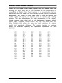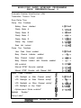
1
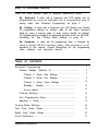
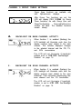
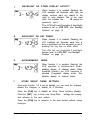
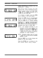
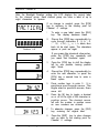
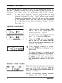
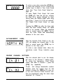
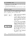
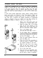
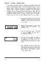
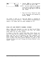
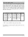
HOW TO PROGRAM RADIOS
There are three different ways to program Bendix/King radios:
*
**
**
By Keyboard A radio with a keyboard and LCD display can be
programmed by using its keyboard and a programming plug or
cloning cable. See “Keyboard Programming” on page 2.
By Cloning A radio with a keyboard and LCD display can transfer
its programmed settings to another radio of the same frequency
band by using a cloning cable. A radio cannot transfer its settings
for Alphanumeric display or optional boards such as UCOM,
scrambling, etc. See “Cloning Radio Settings” on page 20.
By Computer
using a special
described in this
cable, software,
A radio can be programmed from a computer by
RS-232 interface cable. That procedure is not
manual. Contact Bendix/King for the programming
and instruction manual.
TABLE OF CONTENTS
Keyboard Programming ..............................................................
General Settings (Channel 0) ................................................
2
3
Channel 0 Group One Settings .......................................
7
Channel 0 Group Two Settings .......................................
9
Channel 0 Group Three Settings ...................................
12
Backlight
Duration ........................................................
14
Group Labels ................................................................
15
Channel Settings ................................................................
16
Exit Programming Mode ......................................................
19
Selecting a Group ...............................................................
19
Cloning Radio Settings ..............................................................
20
Tone Code Guard Values ..........................................................
24
Digital Code Guard Values ........................................................
25
Quick Reference .......................................................................
27
Keyboard Programming
1
KEYBOARD
PROGRAMMING
This section describes the procedures for programming Bendix/King
radios equipped with a keyboard and LCD display. Most of these
procedures are the same for diff erent types and models, with exceptions
noted where necessary. Required
equipment includes:
Portable radios --------------- programming plug or cloning cable
ENB and LMH mobiles ----- cloning cable
EMV and EMH mobiles----- LAA0290 keyboard microphone, when
available
1.
Remove the covers from the side
connector and the keyboard/display.
2.
Attach a charged battery pack
(portables) or 12V DC power source
(mobiles).
3.
Insert the programming plug or cloning
cable into the side connector
(portables) or mic connector (mobiles).
4.
Select the channel group to be
programmed.
(Not necessary in 14-channel radios.)
See Selecting a Group” on page 19.
5.
Press and hold the master switch.
EMV and EMH: press and hold the far
right button on the front of the radio.
6.
While holding the master switch, press
and hold the [FCN] key. After
approximately three seconds the LCD
will display - - - ID.
7..
Release the [FCN] key and the master
switch. The radio is now in the
password entry mode.
LPH & LMH: no password functionskip steps 8 - 10.
8 . Enter the six-digit password code.
Without the correct password code,,
you cannot proceed with programming.
NOTE: The same password code is
used for all groups in the radio. New
radios are shipped from the factory
with the password code 000000
assigned.
While entering the password code the
display will not change, but a beep will
sound for each key pressed. If the
password code is entered incorrectly,
the radio will reset to normal operation.
Try again, starting at step 4.
9. To keep the password unchanged,
press the [ENT] key and continue with
normal radio programming.
To change the password, press the
[FCN] key and enter a new six-digit
password code. The digits are
displayed as you enter them.
NOTE: Do not use a 1 for the first digit
of the password code - the radio will
malfunction. The password code can
contain the digits 0 through 9, *, and #.
If you make an error entering the new
password code, press the [CLR] key
and try again.
10. Press the [ENT] key to store the new
password
and proceed to
programming mode. The display will
change to PRG Ch 00 (Alphanumeric
display) or PROG Ch 0 (standard 7Segment display).
GENERAL SETTINGS (CHANNEL 0)
Channel 0 is the portion of the program t hat controls general performance
variables for all the channels in a 14-channel radio. For a 21 O-channel
radio, the Channel 0 settings for each group must be programmed
separately.
Select the group to be programmed before entering
Programming Mode. See “Selecting a Group” on page 19.
NOTE: Settings listed as Group One, Group Two, and Group Three
settings refer to Channel 0 programming settings, not channel groups.
Keyboard Programming
3
Press the [FCN] key repeatedly to view
the settings in Channel 0, then loop back
to the Ch 00 entry point. Channel 0
settings include:
Automatic Number Identification (ANI)
Transmitter Time Out Timer
Scan Delay Time
Group One functions:
Battery
Saver
Priority
Scan
Operation
Priority Key Lockout
Scan List Lockout
!
Group Two functions:
PRG
3 *- Q-Jlj5
c .--_---____.--__ J
----_-----
Enable User Code Guard
Busy
Channel
Operation
ANI Enable
DTMF Enable
*Group
Three
functions:
*Backlight Enable Conditions
*Alphanumeric Mode Enable
*Backlight
*Group
NOTE:
Duration
Label
Illustrations show an Alphanumeric Display. The same
procedures are also used to program radios with a standard
7-Segment
display, except the procedures marked with an
asterisk (Alphanumeric Display only).
* Alphanumeric Display only
4
BENDIX/KING
AUTOMATIC NUMBER IDENTIFICATION (ANI)
A.
_-_-_-----~ --After entering the programming mode the
FRG
LCD will display PRG Ch 00
r
Lh
EE
(Alphanumeric)
or PROG CH 0
~__-_-_---~- -- I
(7-Segment).
Press the [FCN] key.
The display will indicatethe AN I ID number
(as many as seven digits may be used).
The ID number can be used for either
radio management or transmitted as a
DTMF tone burst for ANI purposes. The
ANI can be enabled or disabled. See “ANI
ENABLE” on page I0.
If no change is needed for the ID number,
press the [FCN] key to advance to the
next section.
PRG
ID
To enter a new number, press the [CLR]
key, followed by number keys. The digits
will appear at the right side of the display
and move to the left.
To increase the existing ID number by one
digit, press the [PRI] key.
Press the [ENT] key to store the new ID
number and advance to the next section.
If the new ID number will be used only for
cloning, press [FCN] instead of [ENT] to
advance to the next section. The ID
number will not be stored locally.
Keyboard Programming
5
TRANSMITTER TIME OUT TIMER
After the ID number is set, the display
annunciator will indicate PRG TX. This is
the duration of the transmitter Time Out
Timer. 0 SEC means the Time Out Timer
is disabled.
Press the [PRI] key to increase the Time
Out Timer duration by 15 seconds, with a
maximum of 225 seconds (3 minutes, 45
seconds). Press the [PRI] key again to
change the duration from 225 seconds to
zero.
Press the [CLR] key to set the Time Out
Timer duration to zero.
Press the [ENT] key to store the changed
setting and advance to the next section.
Press the [FCN] key to advance to the
next section if no change is needed, or if a
new setting is only to be cloned, not stored
locally.
C .D
SCAN DELAY TIME
After the Time Out Timer is set, the upper
display will indicate PRG SCN. This is the
scan delay time in seconds.
Press the [PRI] key to increase the scan
delaytime by .5 seconds, up to 7.5 seconds.
Press the [PRI] key again to change the
time from 7.5 seconds to 0.
Press the [CLR] key to reset the scan
delay time to 0.
Press the [ENT] key to store the changed
setting and advance to the next section.
Press the [FCN] key to advance to the
next section if no change is needed, or if a
new setting is only to be cloned, not stored
locally.
6
BENDIX/KING
CHANNEL 0 GROUP ONE SETTINGS
1pRG y--
yc7395,
After the scan delay time is set the LCD
will display PRG l-12345. This is a group
of five individual functions that can be
enabled or disabled.
When a function is enabled, the
corresponding number in the display will
flash. When the function is disabled the
number is steady. To change the function
from enabled to disabled or vice versa,
press the number key corresponding to
that function. After making all the desired
changes for group one settings, press the
[ENT] key to save your changes and
advance to the group two settings.
EXAMPLE: If function 4 (Priority Key
Lockout) is disabled, the 4 in the display
will not be flashing. If the [4] key is
pressed, the 4 in the display will flash,
signifying that Priority Key Lockout is
enabled. A subsequent press of the [4]
key will disable Priority Key Lockout.
BATTERY SAVER INHIBIT
When function 1 is enabled (flashing) the
battery saver is turned off . The battery
saver should be turned off only to get
proper voltage readings during service or
in systems requiring extremely fast squelch
attack time.
NOTE:
Bendix/King current drain and battery life specifications are
based on performance with the battery saver on.
Keyboard Programming
7
B.
PRIORITY SCAN
Functions 2 and 3 are used to define Priority Scan operation. There
are three modes of Priority Scan available. They are described in
greater detail in the Owner’s Manual and Service Manual.
PRG
L
7 -0 $33ljrj
- ----- ---.-.-- ----____
Priority Mode A - The Priority Channel
follows the position of the Channel Selector
knob.
Priority Mode B -- The Priority Channel is
fixed. You will transmit on the channel
selected by the Channel Selector knob.
Priority Mode C - The Priority Channel is
fixed. When the PRI toggle switch is on,
the display will show the Priority Channel,
and you will transmit on the Priority Channel
regardless of the Channel Selector knob
setting.
Priority Mode D - Same as Priority Mode
C, except that when the PRI toggle switch
is on, the display will show the channel
selected by the Channel Selector knob.
C.
PRI KEY LOCKOUT
When function 4 is enabled (flashing) the
[PRI] key is locked out in the operating
mode. The user will not be able to change
the designation of the Priority Channel.
When function 4 is disabled (steady) the
user will be able to change the channel
that is designated as Priority Channel.
See ‘Change the Priority Channel” in the
Owner’s Manual.
8
BENDIX/KING
D.
SCAN LIST LOCKOUT
When function 5 is enabled (flashing), the
user will not be able to change thechannels
in the scan list. When disabled (steady),
the user can enter or delete channels from
the scan list. See “Change the Scan List”
in the Owner’s Manual.
E.
STORE GROUP ONE SETTINGS
Once each function l-5 is set as desired, you can store the changes,
discard the changes, or disable all 5 functions.
Press the [CLR] key to disable all Group One functions (steady).
Press the [ENT] key to store new Group One settings into memory
and advance to the next section.
Press the [FCN] key to advance to the next section without saving
changes or if the new settings are only to be cloned, not stored
locally.
CHANNEL 0 GROUP TWO SETTINGS
]I
A.
After Group One functions are set, the
LCD will display PRG 2-12345 for Group
Two functions. As with Group One
functions, the enabled function number
will flash. The disabled functions remain
steady.
USER CODE GUARD SELECTION
When function 1 is enabled (flashing) the
user will be able to press the keyboard to
independently select the Code Guard
values that are programmed into Channels
1 through 9 whileoperatingon any Channel
1 through 14. When disabled the user will
be unable to use the keyboard for Code
Guard selection.
Keyboard Programming
9
B.
BUSY
CHANNEL
OPERATION
NOTE: Group two functions two through five
do not apply to LPH and LMH Series
radios
Functions two and three are used to set
Busy Channel operation. There are three
types of busy channel operation available:
Busy Channel Indicator - The yellow
LED illuminates when a signal is received
on the channel selected, with or without
the programmed receive Code Guard
setting.
Busy Channel Lockout -The yellow LED
illuminates and the transmitter PTT is
disabled when a signal is received without
the programmed receive Code Guard
setting.
Busy Channel Override -This function is
similar to Busy Channel Lockout except
the transmitter PTT can be activated by
rotating the Squelch knob clockwise off
the Code Guard detent.
To set Busy Channel operation use the following chart:
I
BUSY CHANNEL
C.
FUNCTION 2
I
I
FUNCTION 3
INDICATION
DISABLE (STEADY)
ENABLE
(FLASHING)
LOCKOUT
ENABLE
(FLASHING)
ENABLE
(FLASHING)
OVERRIDE
ENABLE
(FLASHING)
DISABLE (STEADY)
I
ANI ENABLE
When function 4 is enabled (flashing) the
ANI ID number will be transmitted (as a
DTMF tone sequence) with each press of
the PTT switch. See “‘Automatic Number
Identification (ANI)” on page 5 for
instructions on setting the ANI number.
10
BENDIX/KING
gj
D.
NOTE: When functions 4 and 5 are both
enabled (flashing) the ANI tone sequence
will be transmitted only after the [ENT] key
is pressed while the transmit PTT switch is
activated. A sidetone of the ANI number
transmitted will also be heard through the
speaker.
DTMF ENABLE
When function 5 is enabled (flashing) the
keypad becomes active for manual DTM F
operation.
E.
STORE GROUP TWO SETTINGS
Once Group Two functions are set, press the [ENT] key to store
them into memory and automatically advance the program to the
next section. Alphanumeric displays advance to Group Three
settings. Standard 7-Segment displays go back to the starting point
for Channel 0 settings.
Once each function l-5 is set as desired, you can store t he changes,
discard the changes, or disable all 5 functions.
Press the [CLR] key to disable all Group Two functions (steady).
Press the [ENT] key to store new Group Two settings into memory
and advance to the next section.
Press the [FCN] key to advance to the next section without saving
changes or if the new settings are only to be cloned, not stored
locally.
NOTE:
If programmed settings are to be cloned (not stored locally)
proceed with the cloning procedure before advancing to the
next section. Otherwise, these settings will be lost. See
‘Cloning Radio Settings” on page 20.
NOTE:
Group Three settings, Alphanumeric display functions,
group labels, and channel labels cannot be transferred by
cloning.
Keyboard Programming
11
CHANNEL 0 GROUP THREE SETTINGS
Group three functions are available only
with Alphanumeric displays
After Group Two functions are set, the
LCD will display PRG 3-12345 for Group
Three functions. As with Group One and
Group Two functions,
theenabledfunction
number will flash. The disabled functions
remain steady.
BACKLIGHT ON MAIN CHANNEL ACTIVITY
When function 1 is enabled (flashing) the
LCD backlight will illuminate each time the
display receives input related to the main
channel. This includes displayed changes
in the selected channel and the PR, TX,
and SCN annunciators.
The LCD will not illuminate if backlight
duration is set to LITE OFF. See”Backlight
Duration” on page 14.
B.
BACKLIGHT ON SCAN CHANNEL ACTIVITY
When function 2 is enabled (flashing) the
LCD backlight will illuminate each time the
display receives input related to the scan
channel. This includes displaying the
scan channel and the CG annunciator.
The LCD will not illuminate if backlight
duration is set to LITE OFF. See“Backlight
Duration” on page 14.
12
X/KING
C.
BACKLIGHT ON OTHER DISPLAY ACTIVITY
When function 3 is enabled (flashing) the
LCD backlight will illuminate each time the
display receives input not related to the
main or scan channel. This is not used
often, but includes the - - - ID prompt for
password input.
The LCD will not illuminate if backlight
duration is set to LITE OFF. See “Backlight
Duration” on page 14.
D.
BACKLIGHT ON KEY PRESS
When function 4 is enabled (flashing) the
LCD backlight will illuminate each time a
key is pressed on the keypad, even if
pressing the key has no other effect.
The LCD will not illuminate if backlight
duration is set to LITE OFF. See “Backlight
Duration” on page 14.
E.
ALPHANUMERIC
MODE
When function 5 is enabled (flashing) the
LCD operates in Alphanumeric mode,
enabling display of channel labels When
disabled (steady) the LCD operates in
standard (7-segment) display mode. This
disables display of channel labels.
F.
STORE GROUP THREE SETTINGS
Once each function 1-5 is set as desired, you can store the changes,
discard the changes, or disable all 5 functions.
Press the [CLR] key to disable all Group Three functions (steady).
Press the [ENT] key to store new Group Three
and advance to the next section.
settings into memory
Press the [FCN] key to advance to the next section without saving
changes.
Keyboard Programming
13
BACKLIGHT
DURATION
Display backlighting is available only with
Alphanumeric
displays.
After Group Three functions, the LCD
displays the current backlight duration
setting. Available settings are LITE OFF,
1 SEC ON, one second increments up to
6 SEC ON, and LITE ON.
If no change is needed, press the [FCN]
key to advance to the next section.
Press the [CLR] key to set backlight
duration to zero and display LITE OFF.
Press the [PRI] key to increase backlight
duration by 1 second increments from
LITE OFF, to 1 SEC ON, 2,3,4,5,6 SEC
ON, LITE ON (illumination remains on
constantly) then back to LITE OFF.
NOTE: The backlight illuminates for the
duration of the new setting. For
example, if you press the [PRI] key to
change the setting from 2 SEC ON to
3 SEC ON the backlight immediately
illuminates for three seconds.
NOTE: Excessive battery drain will result
if LITE ON is set and used for extended
periods of time.
Press the [ENT] key to store changes and
advance to the next function.
Press the [FCN] key to advance to the
next function without storing changes.
14
BENDIX/KING
GROUP LABELS
After the Backlight Duration setting, the LCD displays the current label
for the channel group. Each channel group can have a label of up to
eight characters or spaces.
If no change is needed, press the [FCN]
key to advance to the starting point for
Channel 0 settings.
1.
To enter a new label, press the [CLR]
key. The display becomes blank.
2.
Press the [PRI] key repeatedly to
cycle through characters 0 - 9, A - Z,
-, *, $,/, +,%,\, |,_, c, >, h, blank, then
back tot he start again. The characters
appear in posit ion eight.
1 2 3 4 5 6 7 8
Positions I-8
If you pass the desired character,
press the [PRI] key repeatedly until
you reach that character again.
Keyboard Programming
3.
Press the [FCN] key to shift the display
left by one position, leaving position
eight blank.
4.
Press the [PRI] key repeatedly to
enter the next character, or press the
[FCN] key a second time to enter a
blank space.
5.
Press number keys to enter 0 - 9 in
positions one through seven. The
digits start in position seven, then
move left.
6.
Press the [#] key to toggle a decimal
on or off to the right of the character in
position seven. The decimal moves
left with the number in position seven
as new numbers are entered.
7.
To abandon changes, press the [CLR]
key, restoring the original label.
8.
Press the [ENT] key to store changes
and go back to the starting point for
Channel 0 settings.
15
CHANNEL
SETTINGS
At the starting point for Channel 0, the LCD will display PRG Ch 00. At
this point, a channel number can now be pressed to allow access to the
frequency, Code Guard values, and alphanumeric label for that channel.
NOTE:
1
A valid receive frequency must be programmed into each
channel intended for use. If a 0 value or an invalid
frequency is programmed, the LCD will give a false reading
in the operation mode, and may result in radio malfunction
If a malfunction occurs, reset the radio by turning it off and
then back on
RECEIVE FREQUENCY
1.
Press 1 and the LCD will display PRG
CH 01. This is the starting point for
entering channel 1 values
To move to the next channel, such as
from 1 to 2, press the [PRI] key.
2
q
3D
Press the [FCN] key and the upper
part of the LCD will display PRG RX.
This is the receive frequency for
channel 1 (in MHz).
If the displayed frequency is correct,
press the [FCN] key to advance to the
next value.
If a new frequency is desired, press
the [CLR] key followed by the digits of
the desired frequency. Then press
the [ENT] key to store this frequency
and automatically advance to the next
value.
RECEIVE CODE GUARD
After the receive frequency is set, the
upper part of the LCD will display PRG RX
CG. This is the Code Guard value for
Channel 1 receive.
NOTE: 0.0 indicates carrier squelch
operation (no Code Guard).
16
BENDIX/KING
If the displayed value is correct, press the
[FCN] key to advance to the next value.
To enter a new value, press the [CLR] key
to reset the display to 0.0. Press the
number keys 0 through 9 to enter a Tone
Code Guard value. See “Tone Code
Guard Values” on page 24.
PRG
INDICATES
RX
CG
INVERTED
TRANSMIT
I
I
CODE
To enter a Digital Code Guard value press
the [#] key, causing the letter D to appear
followed by three zeros. Enter the desired
digital code using keys 0 through 7 (keys
8 & 9 do not respond). See “Digital Code
Guard Values” on page 25. Pressing the
[PRI] key after the three-digit code has
been entered allows the digital code to be
inverted. When the displayed value is
correct, press the [ENT] key to store the
Code Guard value and automatically
advance to the next value.
FREQUENCY
After the receive Code Guard is set the
upper part of the LCD will display PRG TX.
This is the transmitter frequency for
Channel 1. If it is correct, press the [FCN]
key to advance to the next value.
PRG 7 X
IA IA
UYJ
If you wish to change it, press the [CLR]
key followed by the frequency in MHz then
[ENT] to store the new frequency and
automatically advance to the next value.
Only valid frequencies will be operable.
TRANSMIT CODE GUARD
After the transmit frequency is set the
upper part of the LCD will display PRG TX
CG. This is the Code Guard value for
Channel 1 transmit (0.0 indicates carrier
squelch). If this value is correct press the
[FCN] key to advance to the next value.
Keyboard Programming
17
To enter a new value, press the [CLR] key
to reset the display to 0.0. Press the
number keys to enter a Tone Code Guard
value. See “Tone Code Guard Values” on
page 24.
To enter Digital Code Guard, first press
the [CLR] key, then the [#] key, causing
the letter D to appear followed by three
zeros Enter the desired digital code using
keys 0 thru 7 (keys 8 & 9 do not respond).
See “Digital Code Guard Values” on page
2 5.
Pressing the [PRI] key after the three digit
code has been entered allows the digital
code to be inverted. When the displayed
value is correct, press the [ENT] key to
store the Code Guard and automatically
advance to the next value.
ALPHANUMERIC
LABEL
After the transmit Code Guard is set, the
LCD will display the channel label. If this
label is correct press the [FCN] key to
proceed to the entry point.
To enter a new channel label, follow the
instructions under “Group Labels”on page
1 5.
REVIEW CHANNEL SETTINGS
After the channel label is set, the display
will return to the Channel 1 starting point.
To review the frequencies, Code Guard
values, and label in Channel 1, press the
[FCN] key repeatedly.
To view and change thevaluesfor another
channel, press the number keys for that
channel, or press the [PRI] key to move up
to the next channel. Each channel can
then be programmed using the same steps
described for Channel 1.
18
BENDIX/KING
EXIT PROGRAMMING MODE
1. Rotate the On/Off/Volume knob on the top of the radio
counterclockwise to the Off position
2.
Remove the programming plug.
3.
The radio will be in normal operation mode the next time it is turned
on.
SELECTING A GROUP
For a 21 O-channel radio, Channel 0 settings affect one “group” of 14
channels. Each group must be programmed separately. To select a
group for programming, perform the following steps:
1.
t
Change the radio from programming
mode to normal operation mode by
turning it off, then on.
In normal operation mode, press the
[#] key to display the current group
number for 5 seconds. Press the [#]
key a second time within 5 seconds to
display the alphanumeric label for the
current group.
2.
To select a group to be programmed,
press the [#] key followed by number
keys for the group number. Enter the
selection by pressing the [#] key or
the [ENT] key, or by waiting 5 seconds.
If an invalid group number has been
selected (for example, group 5) the
LCD will display no group 05. To exit
this mode either turn the radio off,
then on; or enter a valid group number
from the keypad.
3.
NOTE:
Enter the programming mode and set
the values.
See “Keyboard
Programming” on page 2.
The same password code is used for all groups in the radio.
Keyboard Programming
19
CLONING
RADIO
SETTINGS
A radio with a keyboard and LCD display can transfer its programmed
settings to another radio by using a cloning cable. Both units must be
of the same frequency band. For example, an EPH series VHF radio
can transfer settings to or from an LPH or LMH series radio. An EPV
series UHF radio can transfer settings to or from an LPV or EMV series
radio.
A radio cannot transfer Alphanumeric display settings, including channel
labels, group labels, and Channel 0 Group Three functions. Neither can
it transfer settings for optional boards such as UCOM, scrambling, etc.
The radio (with a keyboard and display) transferring its programmed
settings is referred to here as a Master unit. The radio receiving the
programmed settings is referred to here as a Clone unit.
1.
Make sure that both units are
connected to a charged battery pack.
2.
Attach the Master end of the cloning
cable into the side connector of the
Master radio. This is the cable end
with the push-button Master switch.
3.
Turn on the Master radio.
LPH and LMH: skip steps 4 and 5.
4.
Put the Master radio in programming
mode by holding down the Master
switch and pressing the [FCN] key
until the LCD displays - - - ID.
5.
Enter the correct Password Code and
press the [ENT] key.
6 . Press the [FCN] key repeatedly to
review the values in Channel 0. Make
any required changes at this time.
Attach the other end of the cloning
cable into the side connector or mic
connector of the radio to be cloned.
8 . Turn on the clone radio.
9 . Press the [*] key on the Master radio.
Thedisplay will flash PROG, signifying
that the radio is ready to download.
20
BENDIX/KING
10. Press the [FCN] key. The program in
the Master will download to the clone.
The clone will send back the program
to the Master to verify successful
cloning.
g
pm
L
\\\ \ I T,
I///
,~fFJ LL
\ \\\
////I\\\\
11. If the download was successful, the
Master radio will resume flashing
PROG. Turn off the clone radio.
Disconnect the cable. Normal radio
operation will occur the next time the
clone radio is turned on.
12. If the download was not successful
the Master radio will flash FAIL,
followed by continuous beeps. Failure
to download the Master program can
be due to:
A.
B.
C.
D.
NOTE:
Incorrect radio types.
Improper connection.
Failure to power up radio.
Clone set in programming mode.
To stop FAIL mode, press the [CLR] key, turn off the
radios, and start again at Step 1 .
GROUP CLONING
Cloning radios equipped with more than 14 channels (more than
one group) can only be accomplished group by group. Settings for
any group in a Master radio can be downloaded to any group in the
clone radio. To perform group cloning:
1. With the Master radio in normal
operation mode, press the [#] key
followed by number keys to select the
group to be downloaded.
Keyboard Programming
2.
Set the clone radio to the group that is
to receive the download, using the
same method as in step 1 .
3.
Follow thecloning instructionson page
2 0.
21
SPECIAL
CLONING
INSTRUCTIONS
It is possible to change Channel 0 values on the Master radio, hold
them in a temporary memory, and download them to the clone
without actually entering them into the permanent memory of the
Master radio. This is convenient for sequential identification
numbers used to identify a series of portables in a radio system.
Assuming that the frequencies, Code Guard values, and other Ch
0 values are common for all radios in the system, but that the radio
identification number should be unique to each radio, the following
method would be used to clone additional radios for the system.
1. Program the Master radio with all
frequencies, Code Guard values, and
Channel 0 values that will be common
to all radios.
2. Advance the display to show the
Master radio’s ID number -. for
example, 100.
22
3.
Press the [CLR] key; press 1 25. Do
not press the [ENT] key. Now 125 is
in temporary memory.
4.
Press the
the radio
the [FCN]
stored in
clone.
5.
After download, press the [CLR] key.
Disconnect the clone. The Master
radio display will show that 125 is still
being held in the temporary memory
of the Master radio.
[*] key, connect the cable to
and download by pressing
key. ID number 125 is now
permanent memory of the
BENDIX/KING
6.
Press the [PRI] key. This will increment
the ID number one digit to 126.
NOTE: Any new number can be entered
at this point by pressing the [CLR] key
and using the digit keys to enter the
new number.
7.
Press the [*] key. Connect the cable
to the second clone and download by
pressing [FCN].
Any number of radios can be coded with different or sequential ID
numbers using this technique. The ID number in the permanent
memory of the Master radio will remain unchanged as 100.
SCAN LIST AND PRIORITY CHANNEL CLONING
When a Master radio downloads to a clone, the Scan List and Priority
Channel designations are also transferred to the clone. This includes
Priority Mode and any lockout functions.
To program a clone with a specific Priority Mode, Priority Channel, and
Scan List along with the respective lockout functions (if desired), the
Master radio must first be programmed with these parameters. The
lockout functions cannot be held in temporary memory. See “Priority
Scan” on page 8 and “Busy Channel Operation” on page IO. See
Change the Scan List” and “Change the Priority Channel” in the
Owner’s manual.
Keyboard Programming
23
TONE CODE GUARD VALUES
The tone Code Guard system may be set for any frequency in the range
of 67 to 255.9 Hz, However, since most systems adhere to the
Electronic industry Association (EIA) standards, tones should be selected
from the following EIA list. In order to insureoptimum performance, tone
selection for use on the same radio frequency (RF) channel or adjacent
channels in the same coverage area should be made from one of the
Groups A, B, or C to the maximum degree possible. BENDIX/KING
guarantees optimum receiver performance only if tone frequencies
below 220 Hz are chosen.
GROUP A
67.0 (XZ)
77.0 (XB)
88.5 (YB)
*100.0 (1Z)
107.2 (1 B)
114.8 (2A)
123.0 (3Z)
131.8 (3B)
*151.4 (5Z)
162.2 (5B)
173.8 (6A)
186.2 (7Z)
203.5 (Ml)
218.1 (M3)
233.6
250.3
GROUP B
71.9
82.5
94.8
103.5
110.9
GROUP C
(XA)
(YZ)
(ZA)
146.2 (4B)
156.7(5A)
167.9 (6Z)
74.4
79.7
85.4 (YA)
(1A)
*179.9 (6B)
91.5 (ZZ)
(2X)
“118.8 (2B)
127.3 (3A)
136.5 (4Z)
192.8 (7A)
210.7 (M2)
225.7 (M4)
241.8
141.3 (4A)
* 50/60 Hz power distribution systems could cause falsing.
The assignments in a given area shall be made from within one of the
Groups: A, B, or C.
24
BENDIX/KING
DIGITAL CODE GUARD VALUES
Codes for the Digital Code Guard system may be chosen from the
following list. Since there are no EIA standards for the performance or
compatibility of Digital Code Guard systems it is recommended that an
operational test be made on the intended system before wholesale
assignments are made. In some cases either or both the transmit and
receive codes will require an inverted code to operate with existing
systems. This can bedoneduring the code programming of the system.
Usually systems using direct unit to unit transmission (systems without
mobile relays, repeaters, remote control, etc) may use codes from the
table. Systems with relays etc. may use code variations for system
control and operational efficiency. The system operator or engineer
should be consulted regarding the operational requirement on such
systems.
023
025
026
031
032
043
047
051
054
065
071
072
073
074
114
115
116
Keyboardl
Programming
125
131
132
134
143
52
55
56
62
65
72
74
205
223
226
243
244
245
251
261
263
265
271
306
311
315
331
343
346
351
364
365
371
411
412
423
431
432
445
464
465
466
503
506
516
532
546
565
606
612
624
627
631
632
654
662
664
703
712
723
731
732
734
743
754
25
NOTES
26
BENDIX/KING
BENDIX/KING RADIO KEYBOARD PROGRAMMING
QUICK REFERENCE-Channel 0
Automatic Number Identification (ANI)
Transmitter Timeout Timer
Scan Delay Time
Group One Functions
Battery Saver disabled
I@2345
Priority Mode A
l-&345
Priority Mode B
i-q345
Priority Mode C
l-&i45
Priority Mode D
l-l&S
,
Priority Key Lockout
l-123&
Scan List Lockout
i-123&
Group Two Functions
Busy Channel Indicator enabled
29345
7
2-l'2#45,
Busy Channel Lockout enabled
2-I'&5
/
Busy Channel Lockout with Override enabled
ANI enabled
2-l&45
v
2-l;3&5
Manual DTMF Encoder enabled
2-,234
Manual DTMF Encoder with Manual ANI
2-123#@ /
User Code Guard enabled
Group
Three
Functions
LCD Backlight on Main Channel activity*
3g2345
LCD Backlight on Scan Channel activity*
3-I'@45
LCD Backlight on Other Channel activity*
3-Iii45
LCD Backlight on Key Press*
Alphanumeric Mode enabled*
Backlight
Y
I
E
=I
c
3-12%
3-1234
/
Duration*
Group Label*
number indicates active function.
Keyboard Programming
27
BK Radio, Inc.
2901 Lakeview Road
Lawrence, Kansas66049
Telephone:(913)842-0402
FAX:(913)841-0287
0 Copyright 7993 BK Radio, Inc. All tights resetved.
BK Radio Ref. 006-05677-0003
P/N 0301-2044-200
09-94