1
USER INSTRUCTIONS
KP-632 KEYPANEL
EKP-632 EXPANSION PANEL
9350-7711-000 Rev D, 8/2004
PROPRIETARY NOTICE
The RTS product information and design disclosed herein were originated by and are the property of Telex Communications, Inc. telex reserves all patent, proprietary design, manufacturing, reproduction, use and sales rights
thereto, and to any article disclosed therein, except to the extent rights are expressly granted to others.
COPYRIGHT NOTICE
Copyright © 2001 by Telex Communications, Inc. All rights reserved. Reproduction in whole or in part without
prior written permission from Telex is prohibited.
UNPACKING AND INSPECTION
Immediately upon receipt of the equipment, inspect the shipping container and the contents carefully for any discrepancies or damage. Should there be any, notify the freight company and the dealer at once.
WARRANTY INFORMATION
RTS products are warranted by Telex Communications, Inc. to be free from defects in materials and workmanship
for a period of three years from the date of sale.
The sole obligation of Telex during the warranty period is to provide, without charge, parts and labor necessary to
remedy covered defects appearing in products returned prepaid to Telex. This warranty does not cover any defect,
malfunction or failure caused beyond the control of Telex, including unreasonable or negligent operation, abuse,
accident, failure to follow instructions in the Service Manual or the User Manual, defective or improper associated
equipment, attempts at modification and repair not authorized by Telex, and shipping damage. Products with their
serial numbers removed or effaced are not covered by this warranty.
To obtain warranty service, follow the procedures entitled “Procedure For Returns” and “Shipping to Manufacturer
for Repair or Adjustment”.
This warranty is the sole and exclusive express warranty given with respect to RTS products. It is the responsibility
of the user to determine before purchase that this product is suitable for the user's intended purpose.
ANY AND ALL IMPLIED WARRANTIES, INCLUDING THE IMPLIED WARRANTY OF MERCHANTABILITY ARE LIMITED TO THE DURATION OF THIS EXPRESS LIMITED WARRANTY.
NEITHER TELEX NOR THE DEALER WHO SELLS RTS PRODUCTS IS LIABLE FOR INCIDENTAL OR
CONSEQUENTIAL DAMAGES OF ANY KIND.
CUSTOMER SUPPORT
Technical questions should be directed to:
Customer Service Department
RTS/Telex
12000 Portland Avenue South
Burnsville, MN 55337 U.S.A.
Telephone: (952) 884-4051
Fax: (800) 323-0498
RETURN SHIPPING INSTRUCTIONS
PROCEDURE FOR RETURNS
If a repair is necessary, contact the dealer where this unit was purchased.
If repair through the dealer is not possible, obtain a RETURN AUTHORIZATION from:
Customer Service Department
Telex Communications, Inc.
Telephone: (877) 863-4169
Fax: (800) 323-0498
DO NOT RETURN ANY EQUIPMENT DIRECTLY TO THE FACTORY WITHOUT FIRST OBTAINING A
RETURN AUTHORIZATION.
Be prepared to provide the company name, address, phone number, a person to contact regarding the repair, the type
and quantity of equipment, a description of the problem and the serial number(s).
SHIPPING TO MANUFACTURER FOR REPAIR OR ADJUSTMENT
All shipments of RTS products should be made via United Parcel Service or the best available shipper, prepaid. The
equipment should be shipped in the original packing carton; if that is not available, use any suitable container that is
rigid and of adequate size. If a substitute container is used, the equipment should be wrapped in paper and surrounded
with at least four inches of excelsior or similar shock-absorbing material. All shipments must be sent to the following
address and must include the Return Authorization.
Factory Service Department
Telex Communications, Incorporated
West 1st Street
Blue Earth, MN 56013 U.S.A.
Upon completion of any repair the equipment will be returned via United Parcel Service or specified shipper collect.
End-User License Agreement for Telex® Software
IMPORTANT - Please read this document carefully before using this product.
THIS DOCUMENT STATES THE TERMS AND CONDITIONS UPON WHICH TELEX COMMUNICATIONS,
INC. (the “COMPANY”) OFFERS TO LICENSE THE INSTALLED SOFTWARE OR PROGRAM (the “SOFTWARE”) FOR USE WITH THE PRODUCT IN WHICH IT WAS INSTALLED. YOU ARE AGREEING TO
BECOME BOUND BY THE TERMS OF THIS AGREEMENT. IF YOU DO NOT AGREE TO THE TERMS OF
THIS AGREEMENT, DO NOT USE THIS PRODUCT. PROMPTLY RETURN THE PRODUCT TO THE
PLACE WHERE YOU OBTAINED IT FOR A FULL REFUND.
The installed software as supplied by the Company is licensed, not sold, to you for use only under the terms of this
license, and the Company reserves all rights not expressly granted to you. You own the product or other media on or
in which the Software is originally or subsequently recorded or fixed, but the Company retains ownership of all
copies of the Software itself.
1. License: This license allows you to use the Software for internal purposes only on a single product in which it
was installed.
2. Restrictions: (a) You may not market, distribute or transfer copies of the Software to others or electronically
transfer or duplicate the Software. YOU MAY NOT REVERSE ENGINEER, DECOMPILE, DISASSEMBLE,
MODIFY, ADAPT, TRANSLATE, RENT, LEASE OR LOAN THE SOFTWARE OR CREATE DERIVATIVE
WORKS BASED ON THE SOFTWARE OR ANY ACCOMPANYING WRITTEN MATERIALS. (b) The Software and the accompanying written materials are copyrighted. Unauthorized copying of the Software, including
portions thereof or the written materials, is expressly forbidden. (c) You understand that the Company may update
or revise the Software and in so doing incurs no obligation to furnish such updates to you.
3. Limited Warranty: The Company does not warrant that the operation of the Software will meet your requirements or operate free from error. The Company DISCLAIMS ALL OTHER WARRANTIES AND CONDITIONS
EITHER EXPRESS OR IMPLIED, INCLUDING THE WARRANTIES OF MERCHANTABILITY, FITNESS
FOR A PARTICULAR PURPOSE AND NON-INFRINGEMENT OF THIRD PARTY RIGHTS.
4. Limited Liability: The liability of the Company for any claims arising out of this License based upon the Software, regardless of the form of action, shall not exceed the greater of the license fee for the Software or $50.
TABLE OF CONTENTS
Introduction
1-1
Description . . . . . . . . . . . . . . . . . . . .
Features . . . . . . . . . . . . . . . . . . . . .
Options . . . . . . . . . . . . . . . . . . . . . .
GPI/Connector Module . . . . . . . . . . .
CSI-100 Coaxial System Interface Module .
EKP-632 Expansion Keypanel . . . . . . .
LCP-632 Level Control Panel. . . . . . . .
MCP-90 Panel Microphone. . . . . . . . .
Headsets . . . . . . . . . . . . . . . . . .
.
.
.
.
.
.
.
.
.
.
.
.
.
.
.
.
.
.
.
.
.
.
.
.
.
.
.
.
.
.
.
.
.
.
.
.
.
.
.
.
.
.
.
.
.
.
.
.
.
.
.
.
.
.
.
.
.
.
.
.
.
.
.
.
.
.
.
.
.
.
.
.
.
.
.
.
.
.
.
.
.
.
.
.
.
.
.
.
.
.
.
.
.
.
.
.
.
.
.
.
.
.
.
.
.
.
.
.
.
.
.
.
.
.
.
.
.
.
.
.
.
.
.
.
.
.
.
.
.
.
.
.
.
.
.
.
.
.
.
.
.
.
.
.
.
.
.
.
.
.
.
.
.
.
.
.
.
.
.
.
.
.
.
.
.
.
.
.
.
.
.
.
.
.
.
.
.
.
.
.
.
.
.
.
.
.
.
.
.
.
.
.
.
.
.
.
.
.
.
.
.
.
.
.
.
.
.
.
.
.
.
.
.
.
.
.
.
.
.
.
.
.
.
.
.
.
.
.
.
.
.
.
.
.
.
.
.
.
.
.
.
.
.
.
.
.
.
.
.
.
.
.
.
.
.
.
.
.
.
.
.
.
.
.
.
.
.
.
.
.
.
.
.
.
.
.
.
.
.
.
.
.
.
.
.
.
.
.
.
.
.
.
.
.
.
.
.
.
.
.
.
.
.
.
.
.
.
.
.
.
.
.
.
.
.
.
.
.
.
.
.
.
.
.
.
.
.
.
.
.
.
.
.
.
.
.
.
.
.
.
.
.
.
.
.
.
.
.
.
.
.
.
.
.
.
.
.
.
.
.
.
.
.
.
.
.
.
.
.
.
.
.
.
.
.
.
.
.
.
.
.
.
.
.
.
.
.
.
.
.
.
.
.
.
.
.
.
.
.
.
.
.
.
.
.
.
.
.
.
.
.
.
.
.
.
.
.
.
.
.
.
.
.
.
.
.
.
.
.
.
.
.
.
.
.
.
.
.
.
.
.
.
.
.
.
.
.
.
.
.
.
.
.
.
.
.
.
.
.
.
.
.
.
.
.
.
.
.
.
.
.
.
.
.
.
.
.
.
.
.
.
.
.
.
.
.
.
.
.
.
.
.
.
.
.
.
.
.
.
.
.
.
.
.
.
.
.
.
.
.
.
.
.
.
.
.
.
.
.
.
.
.
.
.
.
.
.
.
.
.
.
.
.
.
.
.
.
.
.
.
.
.
.
.
.
.
.
.
.
.
.
.
.
.
.
.
.
.
.
.
.
.
.
.
.
.
.
.
.
.
.
.
.
.
.
.
.
.
.
.
.
.
.
.
.
.
.
.
.
.
.
.
.
.
.
.
.
.
.
.
.
.
.
.
.
.
.
.
.
.
.
.
.
.
.
.
.
.
.
.
.
.
.
.
.
.
.
.
.
.
.
.
.
.
.
.
.
.
.
.
.
.
.
.
.
.
.
.
.
.
.
.
.
.
.
.
.
.
.
.
.
.
.
.
.
.
.
.
.
.
.
.
.
.
.
.
.
.
.
.
.
.
.
.
.
.
.
.
.
.
.
.
.
.
.
.
.
.
.
.
.
.
.
.
.
.
.
.
.
.
.
.
.
.
.
.
.
.
.
.
.
.
.
.
.
.
.
.
.
.
.
.
.
.
.
.
.
.
.
.
.
.
.
.
.
.
.
.
.
.
.
.
.
.
.
.
.
.
.
.
.
.
.
.
.
.
.
.
.
.
.
.
.
.
.
.
.
.
.
.
.
.
.
.
.
.
.
.
.
.
.
.
.
.
.
.
.
.
.
.
.
.
.
.
.
.
.
.
.
.
.
.
.
.
.
.
.
.
.
.
.
.
.
.
.
.
.
.
.
.
.
.
.
.
.
.
.
.
.
.
.
.
.
.
.
.
.
.
.
.
.
.
.
.
.
.
.
.
.
.
.
.
.
.
.
.
.
.
.
.
.
.
.
.
.
.
.
.
.
.
.
.
.
.
.
.
.
.
.
.
.
.
.
.
.
.
.
.
.
.
.
.
.
.
.
.
.
.
.
.
.
.
.
.
.
.
.
.
.
.
.
.
.
.
.
.
.
.
.
.
.
.
.
.
.
.
.
.
.
.
.
.
.
.
.
.
.
.
.
.
.
.
.
.
.
.
.
.
.
.
.
.
.
.
.
.
.
.
.
.
.
.
.
.
.
.
.
.
.
.
.
.
.
.
.
.
.
.
.
.
.
.
.
.
.
.
.
.
.
.
.
.
.
.
.
.
.
.
.
.
.
.
.
.
.
.
.
.
.
.
.
.
.
.
.
.
.
.
.
.
.
.
.
.
.
.
.
.
.
.
.
.
.
.
.
.
.
.
.
.
.
.
.
.
.
.
.
.
.
.
.
.
.
.
.
.
.
.
.
.
.
.
.
.
.
.
.
.
.
.
.
.
.
.
.
.
.
.
.
.
.
.
.
.
.
.
.
.
.
.
.
.
.
.
.
.
.
.
.
.
.
.
.
.
.
.
.
.
.
.
.
.
.
.
.
.
.
.
.
.
.
.
.
.
.
.
.
.
.
.
.
.
.
.
.
.
.
.
.
.
.
.
.
.
.
.
.
.
.
.
.
.
.
.
.
.
.
.
.
.
.
.
.
.
.
.
.
.
.
.
.
.
.
.
.
.
.
.
.
.
.
.
.
.
.
.
.
.
.
.
.
.
.
.
.
.
.
.
.
.
.
.
.
.
.
.
.
.
.
.
.
Screen Saver Operation . . . . . . . . . . . . . . . .
Selecting Headset or Speaker . . . . . . . . . . . . .
Listen Volume Adjustments . . . . . . . . . . . . . . .
Intercom Keys and Displays . . . . . . . . . . . . . .
Alphanumeric Display Indications for Intercom Keys
LED Indications for Intercom Keys. . . . . . . . . .
Talk LED Indications . . . . . . . . . . . . . . .
.
.
.
.
.
.
.
.
.
.
.
.
.
.
.
.
.
.
.
.
.
.
.
.
.
.
.
.
.
.
.
.
.
.
.
.
.
.
.
.
.
.
.
.
.
.
.
.
.
.
.
.
.
.
.
.
.
.
.
.
.
.
.
.
.
.
.
.
.
.
.
.
.
.
.
.
.
.
.
.
.
.
.
.
.
.
.
.
.
.
.
.
.
.
.
.
.
.
.
.
.
.
.
.
.
.
.
.
.
.
.
.
.
.
.
.
.
.
.
.
.
.
.
.
.
.
.
.
.
.
.
.
.
.
.
.
.
.
.
.
.
.
.
.
.
.
.
.
.
.
.
.
.
.
.
.
.
.
.
.
.
.
.
.
.
.
.
.
.
.
.
.
.
.
.
.
.
.
.
.
.
.
.
.
.
.
.
.
.
.
.
.
.
.
.
.
.
.
.
.
.
.
.
.
.
.
.
.
.
.
.
.
.
.
.
.
.
.
.
.
.
.
.
.
.
.
.
.
.
.
.
.
.
.
.
.
.
.
3-1
3-1
3-1
3-2
3-2
3-2
3-2
Continuous Green* . . . . . . . . . . . . . . . . . . . . . . . . . . . . . . . . . . . .
Continuous Red Talk LED & Flashing Display Alpha ("In-use")* . . . . . . . . . . . . .
Flashing Red Talk LED & Flashing Display Alternating Pattern of Alpha & (-**-) ("Busy")
Flashing Green Talk LED & Display Alpha (on time equal to off time)* . . . . . . . . . .
Winking Green Talk LED (on time less than off time)* . . . . . . . . . . . . . . . . . .
.
.
.
.
.
.
.
.
.
.
.
.
.
.
.
.
.
.
.
.
.
.
.
.
.
.
.
.
.
.
.
.
.
.
.
.
.
.
.
.
.
.
.
.
.
.
.
.
.
.
.
.
.
.
.
. 3-2
. 3-2
. 3-2
. 3-3
. 3-3
.
.
.
.
.
.
.
.
.
.
.
.
.
.
.
.
.
.
.
.
.
.
.
.
.
.
.
.
.
.
.
.
.
.
.
.
.
.
.
.
.
.
.
.
3-3
3-3
3-3
3-3
Installation
Option DIP Switch Settings . . . . . . . . . . .
Switch 1: Latch Enable/Disable . . . . .
Switch 2: Key Gain Enable / Disable . . .
Switch 3: Screen Saver Enable / Disable.
Switch 4: Call Flash Timeout . . . . . . .
Switch 5: Footswitch Enable / Disable*. .
Switch 6: Network Mode Selection . . . .
Switch 7: Test/Debug . . . . . . . . . . .
Switch 8: Test/Debug . . . . . . . . . . .
Address Switch Setting . . . . . . . . . . . . .
General Information . . . . . . . . . . . . .
Address Setting for Zeus . . . . . . . . . .
Address Setting for ADAM CS. . . . . . . .
ADAM CS with RJ12 or DB-9 back panel:
ADAM CS with 50-pin Telco back panel: .
Address Setting for ADAM. . . . . . . . . .
Connections . . . . . . . . . . . . . . . . . .
EXP. Connectors. . . . . . . . . . . . . . .
Frame Connector . . . . . . . . . . . . . .
Power Supply Connector . . . . . . . . . . . .
Headset Connector . . . . . . . . . . . . . . .
Headset Microphone Gain Adjustment . . .
Panel Microphone Connector . . . . . . . . . .
Panel Microphone Gain Adjustment . . . . .
1-1
1-1
1-2
1-2
1-2
1-3
1-3
1-3
1-3
2-1
.
.
.
.
.
.
.
.
.
.
.
.
.
.
.
.
.
.
.
.
.
.
.
.
Basic Operation
Listen LED Indication. . . . . . . . . . . . . . .
Intercom Key Operation . . . . . . . . . . . . . . .
Basic Intercom Key Operation . . . . . . . . . .
Operation of Intercom Keys with Auto Functions .
2-1
2-1
2-1
2-1
2-2
2-2
2-2
2-2
2-2
2-2
2-2
2-3
2-3
2-3
2-4
2-5
2-5
2-5
2-5
2-6
2-6
2-6
2-7
2-7
3-1
.
.
.
.
.
.
.
.
.
.
.
.
.
.
.
.
.
.
.
.
.
.
.
.
.
.
.
.
.
.
.
.
.
.
.
.
.
.
.
.
.
.
.
.
.
.
.
.
.
.
.
.
.
.
.
.
.
.
.
.
.
.
.
.
.
.
.
.
.
.
.
.
.
.
.
.
.
.
.
.
.
.
.
.
.
.
.
.
.
.
.
.
.
.
.
.
.
.
.
.
.
.
.
.
.
.
.
.
.
.
.
.
.
.
.
.
.
.
.
.
.
.
.
.
.
.
.
.
.
.
.
.
Talk + auto follow . . . . . . . . . . . . . . . . . . . . . . . . . . . . . . . . . . . . . . . . . . . . . . . . . . . . . . . . . 3-3
Talk + auto listen . . . . . . . . . . . . . . . . . . . . . . . . . . . . . . . . . . . . . . . . . . . . . . . . . . . . . . . . . 3-3
i
Talk + auto mute . . .
Talk + auto reciprocal
Talk + auto table . . .
All Call Key . . . . . .
Talk + DIM . . . . . .
.
.
.
.
.
.
.
.
.
.
.
.
.
.
.
.
.
.
.
.
.
.
.
.
.
.
.
.
.
.
.
.
.
.
.
.
.
.
.
.
.
.
.
.
.
.
.
.
.
.
.
.
.
.
.
.
.
.
.
.
.
.
.
.
.
.
.
.
.
.
.
.
.
.
.
.
.
.
.
.
.
.
.
.
.
.
.
.
.
.
.
.
.
.
.
.
.
.
.
.
.
.
.
.
.
.
.
.
.
.
.
.
.
.
.
.
.
.
.
.
.
.
.
.
.
.
.
.
.
.
.
.
.
.
.
.
.
.
.
.
.
.
.
.
.
.
.
.
.
.
.
.
.
.
.
.
.
.
.
.
.
.
.
.
.
.
.
.
.
.
.
.
.
.
.
.
.
.
.
.
.
.
.
.
.
.
.
.
.
.
.
.
.
.
.
.
.
.
.
.
.
.
.
.
.
.
.
.
.
.
.
.
.
.
.
.
.
.
.
.
.
.
.
.
.
.
.
.
.
.
.
.
.
.
.
.
.
.
.
.
.
.
.
.
.
.
.
.
.
.
.
.
.
.
.
.
.
.
.
.
.
.
.
.
.
.
.
.
.
.
3-3
3-4
3-4
3-4
3-4
Operation of Intercom Keys with Options . . . . . . . . . . . . . . . . . . . . . . . . . . . . . . . . . . . . . . . 3-4
Group Option Keys . . . . . . . . . . . . . . . . . . . . . . . . . . . . . . . . . . . . . . . . . . . . . . . . . . . . . . . . 3-4
Solo Key . . . . . . . . . . . . . . . . . . . . . . . . . . . . . . . . . . . . . . . . . . . . . . . . . . . . . . . . . . . . . 3-4
Operation of Intercom Talk Keys with the Speaker DIM Setting
Operation of Intercom Keys assigned to TIF Ports. . . . . . .
Muting the Microphone . . . . . . . . . . . . . . . . . . . . . . . .
Call Waiting Operation . . . . . . . . . . . . . . . . . . . . . . . .
.
.
.
.
.
.
.
.
.
.
.
.
.
.
.
.
.
.
.
.
.
.
.
.
.
.
.
.
.
.
.
.
.
.
.
.
.
.
.
.
.
.
.
.
.
.
.
.
.
.
.
.
.
.
.
.
.
.
.
.
.
.
.
.
.
.
.
.
.
.
.
.
.
.
.
.
.
.
.
.
.
.
.
.
.
.
.
.
.
.
.
.
.
.
.
.
.
.
.
.
.
.
.
.
.
.
.
.
. 3-4
. 3-4
. 3-5
. 3-5
Receiving A Phone Call . . . . . . . . . . . . . . . . . . . . . . . .
DIALING AND HANGING UP USING KP9X KEYPAD SEQUENCES .
KP9X Keypad Hang-up Sequence . . . . . . . . . . . . . . . . .
KP9X Manual dial sequence . . . . . . . . . . . . . . . . . . . .
KP9X Redial Sequence . . . . . . . . . . . . . . . . . . . . . . .
KP9X Autodial Sequences . . . . . . . . . . . . . . . . . . . . .
Storing an Autodial Number in the TIF-951 / TIF-2000 . . . . . . .
Dialing an Autodial Number Stored in the TIF-951 / TIF-2000 . . .
DIALING AND HANGING UP USING THE KP-632 DIALING MENU .
Manual Dialing . . . . . . . . . . . . . . . . . . . . . . . . . . .
Redial . . . . . . . . . . . . . . . . . . . . . . . . . . . . . . . .
Autodial . . . . . . . . . . . . . . . . . . . . . . . . . . . . . . .
.
.
.
.
.
.
.
.
.
.
.
.
.
.
.
.
.
.
.
.
.
.
.
.
.
.
.
.
.
.
.
.
.
.
.
.
.
.
.
.
.
.
.
.
.
.
.
.
.
.
.
.
.
.
.
.
.
.
.
.
.
.
.
.
.
.
.
.
.
.
.
.
.
.
.
.
.
.
.
.
.
.
.
.
.
.
.
.
.
.
.
.
.
.
.
.
.
.
.
.
.
.
.
.
.
.
.
.
.
.
.
.
.
.
.
.
.
.
.
.
.
.
.
.
.
.
.
.
.
.
.
.
.
.
.
.
.
.
.
.
.
.
.
.
.
.
.
.
.
.
.
.
.
.
.
.
.
.
.
.
.
.
.
.
.
.
.
.
.
.
.
.
.
.
.
.
.
.
.
.
.
.
.
.
.
.
.
.
.
.
.
.
.
.
.
.
.
.
.
.
.
.
.
.
.
.
.
.
.
.
.
.
.
.
.
.
.
.
.
.
.
.
.
.
.
.
.
.
.
.
.
.
.
.
.
.
.
.
.
.
.
.
.
.
.
.
.
.
.
.
.
.
.
.
.
.
.
.
.
.
.
.
.
.
.
.
.
.
.
.
.
.
.
.
.
.
.
.
.
.
.
.
.
.
.
.
.
.
.
.
.
.
.
.
.
.
.
.
.
.
.
.
.
.
.
.
.
.
.
.
.
.
. 4-1
. 4-1
. 4-1
. 4-1
. 4-2
. 4-2
. 4-2
. 4-3
. 4-3
. 4-3
. 4-3
. 4-4
KEYPAD PROGRAMMING, DISPLAY REQUESTS . . . . . . . . . . . . . . . . . .
Display Requests Using Keypad Sequences . . . . . . . . . . . . . . . . . . . .
Display Panel ID. . . . . . . . . . . . . . . . . . . . . . . . . . . . . . . . . . .
Display Level 2 Talk Key Assignments . . . . . . . . . . . . . . . . . . . . . . .
Display Listen Key Assignments . . . . . . . . . . . . . . . . . . . . . . . . . .
Display Setup Page Assignments . . . . . . . . . . . . . . . . . . . . . . . . . .
Test Keys and Displays . . . . . . . . . . . . . . . . . . . . . . . . . . . . . . .
Tone Generator Activation (FUNC-DISPLAY-7) . . . . . . . . . . . . . . . . . . .
Display Requests Using Scrolling . . . . . . . . . . . . . . . . . . . . . . . . . .
KEYPAD PROGRAMMING, ASSIGNING SETUP PAGES . . . . . . . . . . . . . . .
KEYPAD PROGRAMMING, ASSIGNING INTERCOM KEYS . . . . . . . . . . . . .
General . . . . . . . . . . . . . . . . . . . . . . . . . . . . . . . . . . . . . . .
Assigning Keys Using Keypad Numeric Entry . . . . . . . . . . . . . . . . . . .
General Procedure. . . . . . . . . . . . . . . . . . . . . . . . . . . . . . . .
Programming Key Assignments Using Copy . . . . . . . . . . . . . . . . . . . .
Copying a Call from the Call waiting Window to a Key . . . . . . . . . . . . . . .
Copying One Key Assignment to Another Key . . . . . . . . . . . . . . . . . . .
Programming Key Assignments Using Alpha Scrolling . . . . . . . . . . . . . . .
Clearing a Key Assignment . . . . . . . . . . . . . . . . . . . . . . . . . . . . .
Method 1: Clearing the Call waiting Window and Copying it to a Key . . . . . .
Method 2: Copying a Blank Key Assignment to the Key that You want to Clear .
.
.
.
.
.
.
.
.
.
.
.
.
.
.
.
.
.
.
.
.
.
.
.
.
.
.
.
.
.
.
.
.
.
.
.
.
.
.
.
.
.
.
.
.
.
.
.
.
.
.
.
.
.
.
.
.
.
.
.
.
.
.
.
.
.
.
.
.
.
.
.
.
.
.
.
.
.
.
.
.
.
.
.
.
.
.
.
.
.
.
.
.
.
.
.
.
.
.
.
.
.
.
.
.
.
.
.
.
.
.
.
.
.
.
.
.
.
.
.
.
.
.
.
.
.
.
.
.
.
.
.
.
.
.
.
.
.
.
.
.
.
.
.
.
.
.
.
.
.
.
.
.
.
.
.
.
.
.
.
.
.
.
.
.
.
.
.
.
.
.
.
.
.
.
.
.
.
.
.
.
.
.
.
.
.
.
.
.
.
.
.
.
.
.
.
.
.
.
.
.
.
.
.
.
.
.
.
.
.
.
.
.
.
.
.
.
.
.
.
.
.
.
.
.
.
.
.
.
.
.
.
.
.
.
.
.
.
.
.
.
.
.
.
.
.
.
.
.
.
.
.
.
.
.
.
.
.
.
.
.
.
.
.
.
.
.
.
.
.
.
.
.
.
.
.
.
.
.
.
.
.
.
.
.
.
.
.
.
.
.
.
.
.
.
.
.
.
.
.
.
.
.
.
.
.
.
.
.
.
.
.
.
.
.
.
.
.
.
.
.
.
.
.
.
.
.
.
.
.
.
.
.
.
.
.
.
.
.
.
.
.
.
.
.
.
.
.
.
.
.
.
.
.
.
.
.
.
.
.
.
.
.
.
.
.
.
.
.
.
.
.
.
.
.
.
.
.
.
. 5-1
. 5-1
. 5-1
. 5-1
. 5-1
. 5-2
. 5-2
. 5-3
. 5-3
. 5-3
. 5-4
. 5-4
. 5-4
. 5-4
. 5-5
. 5-5
. 5-5
. 5-6
. 5-7
. 5-7
. 5-7
.
.
.
.
.
.
.
.
.
.
.
.
.
.
.
.
.
.
.
.
.
.
.
.
.
.
.
.
.
.
.
.
.
.
.
.
.
.
.
.
.
.
.
.
.
.
.
.
.
.
.
.
.
.
.
.
.
.
.
.
.
.
.
.
.
.
.
.
.
.
.
.
.
.
.
.
.
.
.
.
.
.
.
.
.
.
.
.
.
.
.
.
.
.
.
.
.
.
.
.
.
.
.
.
.
.
.
.
.
.
.
.
.
.
.
.
.
.
.
.
.
.
.
.
.
.
.
.
.
.
.
.
.
.
.
.
.
.
.
.
.
.
.
.
.
.
.
.
.
.
.
.
.
.
.
.
.
.
.
.
.
.
. 6-1
. 6-1
. 6-1
. 6-2
. 6-2
. 6-2
. 6-2
. 6-2
. 6-2
Telephone Operation
4-1
KP9X Series Keypad Programming
5-1
KP-632 Menu System
MENU SYSTEM, MENU ACCESS .
MENU SYSTEM, DISPLAY MENU .
Display Menu, Asgn Type . . . .
Display Menu, Chans On . . . .
Display Menu, Key Groups . . .
Display Menu, Key List . . . . .
Display Menu, Level 2 . . . . . .
Display Menu, Listen . . . . . .
Display Menu, Matrix . . . . . .
6-1
.
.
.
.
.
.
.
.
.
.
.
.
.
.
.
.
.
.
.
.
.
.
.
.
.
.
.
.
.
.
.
.
.
.
.
.
.
.
.
.
.
.
.
.
.
.
.
.
.
.
.
.
.
.
.
.
.
.
.
.
.
.
.
.
.
.
.
.
.
.
.
.
.
.
.
.
.
.
.
.
.
.
.
.
.
.
.
.
.
.
.
.
.
.
.
.
.
.
.
.
.
.
.
.
.
.
.
.
.
.
.
.
.
.
.
.
.
.
.
.
.
.
.
.
.
.
.
.
.
.
.
.
.
.
.
ii
.
.
.
.
.
.
.
.
.
.
.
.
.
.
.
.
.
.
.
.
.
.
.
.
.
.
.
.
.
.
.
.
.
.
.
.
.
.
.
.
.
.
.
.
.
.
.
.
.
.
.
.
.
.
.
.
.
.
.
.
.
.
.
.
.
.
.
.
.
.
.
.
.
.
.
.
.
.
.
.
.
.
.
.
.
.
.
.
.
.
.
.
.
.
.
.
.
.
.
Display Menu, Panel ID . . . . . . . . . . . . . . . . .
Display Menu, Version . . . . . . . . . . . . . . . . . .
MENU SYSTEM, KEY ASSIGN MENU. . . . . . . . . . .
General Procedure to use the Key Assign Menu . . . .
Key Assign Menu, Matrix . . . . . . . . . . . . . . . .
Key Assign Menu, Pt-to-Pt. . . . . . . . . . . . . . . .
Key Assign Menu, Party Line . . . . . . . . . . . . . .
Key Assign Menu, IFB . . . . . . . . . . . . . . . . . .
Key Assign Menu, Spcl List . . . . . . . . . . . . . . .
Key Assign Menu, Sys Relay . . . . . . . . . . . . . .
Key Assign Menu, Camera ISO . . . . . . . . . . . . .
Key Assign Menu, UPL Resrc . . . . . . . . . . . . . .
Key Assign Menu, Auto Func . . . . . . . . . . . . . .
Key Assign Menu, Key Gain . . . . . . . . . . . . . . .
Key Assign Menu, Reset Vols . . . . . . . . . . . . . .
Key Assign Menu, Setup Page . . . . . . . . . . . . .
KEY OPTION MENU . . . . . . . . . . . . . . . . . . . .
Key Option Menu, Auto Dial . . . . . . . . . . . . . . .
Key Option Menu, Chime . . . . . . . . . . . . . . . .
Removing the chime option from a key. . . . . . . .
Key Option Menu, Key Groups . . . . . . . . . . . . .
Clearing a key group. . . . . . . . . . . . . . . . . . .
Key Option Menu, Solo . . . . . . . . . . . . . . . . .
Removing the solo key option . . . . . . . . . . . .
SERVICE MENU . . . . . . . . . . . . . . . . . . . . . .
Service Menu, Aux Inputs . . . . . . . . . . . . . . . .
Service Menu, Dim . . . . . . . . . . . . . . . . . . .
Service Menu, Disply Dim . . . . . . . . . . . . . . . .
Service Menu, DSP Func . . . . . . . . . . . . . . . .
Filtering . . . . . . . . . . . . . . . . . . . . . . . .
Gating . . . . . . . . . . . . . . . . . . . . . . . .
Metering . . . . . . . . . . . . . . . . . . . . . . .
Mixing . . . . . . . . . . . . . . . . . . . . . . . .
Service Menu, Hdst Sel . . . . . . . . . . . . . . . . .
Service Menu, LCD Bright. . . . . . . . . . . . . . . .
Service Menu, LCP-632 . . . . . . . . . . . . . . . . .
Service Menu, Local GPIO . . . . . . . . . . . . . . .
Assigning an Input to Activate a Key . . . . . . . . .
Assigning an Input to Activate a Key Group . . . . .
Removing an Input Assignment . . . . . . . . . . .
Adding or Removing a GPI Output Key Assignment .
Service Menu, Matrix Out . . . . . . . . . . . . . . . .
Service Menu, Mic Select . . . . . . . . . . . . . . . .
Service Menu, Min Volume . . . . . . . . . . . . . . .
Service Menu, Mod Assign . . . . . . . . . . . . . . .
Service Menu, Output Level . . . . . . . . . . . . . . .
Service Menu, Preamp Out (GPI Option Only) . . . . .
Service Menu, Reset Cfg . . . . . . . . . . . . . . . .
Service Menu, Save Cfg . . . . . . . . . . . . . . . . .
Service Menu, Sidetone . . . . . . . . . . . . . . . . .
Service Menu, Test Panel . . . . . . . . . . . . . . . .
Service Menu, Tone Gen . . . . . . . . . . . . . . . .
.
.
.
.
.
.
.
.
.
.
.
.
.
.
.
.
.
.
.
.
.
.
.
.
.
.
.
.
.
.
.
.
.
.
.
.
.
.
.
.
.
.
.
.
.
.
.
.
.
.
.
.
.
.
.
.
.
.
.
.
.
.
.
.
.
.
.
.
.
.
.
.
.
.
.
.
.
.
.
.
.
.
.
.
.
.
.
.
.
.
.
.
.
.
.
.
.
.
.
.
.
.
.
.
.
.
.
.
.
.
.
.
.
.
.
.
.
.
.
.
.
.
.
.
.
.
.
.
.
.
.
.
.
.
.
.
.
.
.
.
.
.
.
.
.
.
.
.
.
.
.
.
.
.
.
.
.
.
.
.
.
.
.
.
.
.
.
.
.
.
.
.
.
.
.
.
.
.
.
.
.
.
.
.
.
.
.
.
.
.
.
.
.
.
.
.
.
.
.
.
.
.
.
.
.
.
.
.
.
.
.
.
.
.
.
.
.
.
.
.
.
.
.
.
.
.
.
.
.
.
.
.
.
.
.
.
.
.
.
.
.
.
.
.
.
.
.
.
.
.
.
.
.
.
.
.
.
.
.
.
.
.
.
.
.
.
.
.
.
.
.
.
.
.
.
.
.
.
.
.
.
.
.
.
.
.
.
.
.
.
.
.
.
.
.
.
.
.
.
.
.
.
.
.
.
.
.
.
.
.
.
.
.
.
.
.
.
.
.
.
.
.
.
.
.
.
.
.
.
.
.
.
.
.
.
.
.
.
.
.
.
.
.
.
.
.
.
.
.
.
.
.
.
.
.
.
.
.
.
.
.
.
.
.
.
.
.
.
.
.
.
.
.
.
.
.
.
.
.
.
.
.
.
.
.
.
.
.
.
.
.
.
.
.
.
.
.
.
.
.
.
.
.
.
.
.
.
.
.
.
.
.
.
.
.
.
.
.
.
.
.
.
.
.
.
.
.
.
.
.
.
.
.
.
.
.
.
.
.
.
.
.
.
.
.
.
.
.
.
.
.
.
.
.
.
.
.
.
.
.
.
.
.
.
.
.
.
.
.
.
.
.
.
.
.
.
.
.
.
.
.
.
.
.
.
.
.
.
.
.
.
.
.
.
.
.
.
.
.
.
.
.
.
.
.
.
.
.
.
.
.
.
.
.
.
.
.
.
.
.
.
.
.
.
.
.
.
.
.
.
.
.
.
.
.
.
.
.
.
.
.
.
.
.
.
.
.
.
.
.
.
.
.
.
.
.
.
.
.
.
.
.
.
.
.
.
.
.
.
.
.
.
.
.
.
.
.
.
.
.
.
.
.
.
.
.
.
.
.
.
.
.
.
.
.
.
.
.
.
.
.
.
.
.
.
.
.
.
.
.
.
.
.
.
.
.
.
.
.
.
.
.
.
.
.
.
.
.
.
.
.
.
.
.
.
.
.
.
.
.
.
.
.
.
.
.
.
.
.
.
.
.
.
.
.
.
.
.
.
.
.
.
.
.
.
.
.
.
.
.
.
.
.
.
.
.
.
.
.
.
.
.
.
.
.
.
.
.
.
.
.
.
.
.
.
.
.
.
.
.
.
.
.
.
.
.
.
.
.
.
.
.
.
.
.
.
.
.
.
.
.
.
.
.
.
.
.
.
.
.
.
.
.
.
.
.
.
.
.
.
.
.
.
.
.
.
.
.
.
.
.
.
.
.
.
.
.
.
.
.
.
.
.
.
.
.
.
.
.
.
.
.
.
.
.
.
.
.
.
.
.
.
.
.
.
.
.
.
.
.
.
.
.
.
.
.
.
.
.
.
.
.
.
.
.
.
.
.
.
.
.
.
.
.
.
.
.
.
.
.
.
.
.
.
.
.
.
.
.
.
.
.
.
.
.
.
.
.
.
.
.
.
.
.
.
.
.
.
.
.
.
.
.
.
.
.
.
.
.
.
.
.
.
.
.
.
.
.
.
.
.
.
.
.
.
.
.
.
.
.
.
.
.
.
.
.
.
.
.
.
.
.
.
.
.
.
.
.
.
.
.
.
.
.
.
.
.
.
.
.
.
.
.
.
.
.
.
.
.
.
.
.
.
.
.
.
.
.
.
.
.
.
.
.
.
.
.
.
.
.
.
.
.
.
.
.
.
.
.
.
.
.
.
.
.
.
.
.
.
.
.
.
.
.
.
.
.
.
.
.
.
.
.
.
.
.
.
.
.
.
.
.
.
.
.
.
.
.
.
.
.
.
.
.
.
.
.
.
.
.
.
.
.
.
.
.
.
.
.
.
.
.
.
.
.
.
.
.
.
.
.
.
.
.
.
.
.
.
.
.
.
.
.
.
.
.
.
.
.
.
.
.
.
.
.
.
.
.
.
.
.
.
.
.
.
.
.
.
.
.
.
.
.
.
.
.
.
.
.
.
.
.
.
.
.
.
.
.
.
.
.
.
.
.
.
.
.
.
.
.
.
.
.
.
.
.
.
.
.
.
.
.
.
.
.
.
.
.
.
.
.
.
.
.
.
.
.
.
.
.
.
.
.
.
.
.
.
.
.
.
.
.
.
.
.
.
.
.
.
.
.
.
.
.
.
.
.
.
.
.
.
.
.
.
.
.
.
.
.
.
.
.
.
.
.
.
.
.
.
.
.
.
.
.
.
.
.
.
.
.
.
.
.
.
.
.
.
.
.
.
.
.
.
.
.
.
.
.
.
.
.
.
.
.
.
.
.
.
.
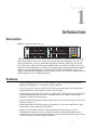
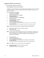
.
.
.
.
.
.
.
.
.
.
.
.
.
.
.
.
.
.
.
.
.
.
.
.
.
.
.
.
.
.
.
.
.
.
.
.
.
.
.
.
.
.
.
.
.
.
.
.
.
.
.
.
.
.
.
.
.
.
.
.
.
.
.
.
.
.
.
.
.
.
.
.
.
.
.
.
.
.
.
.
.
.
.
.
.
.
.
.
.
.
.
.
.
.
.
.
.
.
.
.
.
.
.
.
.
.
.
.
.
.
.
.
.
.
.
.
.
.
.
.
.
.
.
.
.
.
.
.
.
.
.
.
.
.
.
.
.
.
.
.
.
.
.
.
.
.
.
.
.
.
.
.
.
.
.
.
.
.
.
.
.
.
.
.
.
.
.
.
.
.
.
.
.
.
.
.
.
.
.
.
.
.
.
.
.
.
.
.
.
.
.
.
.
.
.
.
.
.
.
.
.
.
.
.
.
.
.
.
.
.
.
.
.
.
.
.
.
.
.
.
.
.
.
.
.
.
.
.
.
.
.
.
.
.
.
.
.
.
.
.
.
.
.
.
.
.
.
.
.
.
.
.
.
.
.
.
.
.
.
.
.
.
.
.
.
.
.
.
.
.
.
.
.
.
.
.
.
.
.
.
.
.
.
.
.
.
.
.
.
.
.
.
.
.
.
.
.
.
.
.
.
.
.
.
.
.
.
.
.
.
.
.
.
.
.
.
.
.
.
.
.
.
.
.
.
.
.
.
.
.
.
.
.
.
.
.
.
.
.
.
.
.
.
.
.
.
.
.
.
.
.
.
.
.
.
.
.
.
.
.
.
.
.
.
.
.
.
.
.
.
.
.
.
.
.
.
.
.
.
.
.
.
.
.
.
.
.
.
.
.
.
.
.
.
.
.
.
.
.
.
.
.
.
. 6-2
. 6-2
. 6-3
. 6-3
. 6-4
. 6-4
. 6-5
. 6-5
. 6-5
. 6-5
. 6-5
. 6-5
. 6-5
. 6-6
. 6-6
. 6-7
. 6-7
. 6-7
. 6-7
. 6-8
. 6-8
. 6-8
. 6-9
. 6-9
. 6-9
. 6-9
. 6-9
. 6-10
. 6-10
. 6-11
. 6-11
. 6-11
. 6-12
. 6-12
. 6-13
. 6-13
. 6-14
. 6-14
. 6-14
. 6-15
. 6-15
. 6-15
. 6-16
. 6-16
. 6-16
. 6-17
. 6-17
. 6-18
. 6-18
. 6-18
. 6-18
. 6-18
.
.
.
.
.
.
.
.
.
.
.
.
.
.
.
.
.
.
.
.
.
.
.
.
.
.
.
.
.
.
.
.
.
.
.
.
.
.
.
.
.
.
.
.
.
.
.
.
.
.
.
.
.
.
.
.
.
.
.
.
.
.
.
.
.
.
.
.
.
.
.
.
.
.
.
.
.
.
.
.
.
.
.
.
.
.
.
.
.
.
.
.
.
.
.
.
.
.
.
.
.
.
.
.
.
.
.
.
.
.
.
.
.
.
.
.
.
.
.
.
.
.
.
.
.
.
.
.
.
.
.
.
.
.
.
.
.
.
.
.
.
.
.
.
.
.
.
.
.
.
.
.
.
.
.
.
.
.
.
.
.
.
.
.
.
.
.
.
.
.
.
.
.
.
.
.
.
.
.
.
.
.
.
.
.
.
.
.
.
.
.
.
Specifications
Microphone Preamplifier . . . . . . . . . . . .
Tone Generator . . . . . . . . . . . . . . . . .
Headphone Amplifier . . . . . . . . . . . . . .
Speaker Amplifier and Speaker. . . . . . . . .
Intercom Balanced Line Input/Output. . . . . .
External Balanced Line Input: (Program Input) .
7-1
.
.
.
.
.
.
.
.
.
.
.
.
.
.
.
.
.
.
.
.
.
.
.
.
.
.
.
.
.
.
.
.
.
.
.
.
iii
7-1
7-1
7-1
7-1
7-2
7-2
General . . . . . . . . . . . . . . . . . . . . . . . . . . . . . . . .
AC Supply: . . . . . . . . . . . . . . . . . . . . . . . . . . .
Environmental: . . . . . . . . . . . . . . . . . . . . . . . . .
Approvals: . . . . . . . . . . . . . . . . . . . . . . . . . . .
Connectors (Other connector options available) . . . . . . . . . . .
Panel Microphone Connector (Electret) . . . . . . . . . . . . . .
Headset Connector (Dynamic) . . . . . . . . . . . . . . . . . .
Power Input Connector . . . . . . . . . . . . . . . . . . . . . .
Intercom Connectors: Parallel-wired DE9S and RJ12 Connectors
Expansion Connector . . . . . . . . . . . . . . . . . . . . . . .
LCP Connector . . . . . . . . . . . . . . . . . . . . . . . . . .
GPI Module Conntectors (Optional) . . . . . . . . . . . . . . . . .
Aux 1 In (Auxiliary program input 1). . . . . . . . . . . . . . . .
Aux 2 In (Auxiliary program input 2). . . . . . . . . . . . . . . .
Relay 1 & 2 Out . . . . . . . . . . . . . . . . . . . . . . . . . .
Relay 3 & 4 Out . . . . . . . . . . . . . . . . . . . . . . . . . .
Opto 1-4 In (Opto-isolated control inputs). . . . . . . . . . . . .
OC 1 & 2 Out (J2) . . . . . . . . . . . . . . . . . . . . . . . . .
Headset (External headset connector) . . . . . . . . . . . . . .
Foot Switch/Speaker . . . . . . . . . . . . . . . . . . . . . . .
MIC In (J7) Balanced Microphone Output. . . . . . . . . . . . .
MIC Out (J8) Balanced Microphone Output. . . . . . . . . . . .
.
.
.
.
.
.
.
.
.
.
.
.
.
.
.
.
.
.
.
.
.
.
.
.
.
.
.
.
.
.
.
.
.
.
.
.
.
.
.
.
.
.
.
.
.
.
.
.
.
.
.
.
.
.
.
.
.
.
.
.
.
.
.
.
.
.
.
.
.
.
.
.
.
.
.
.
.
.
.
.
.
.
.
.
.
.
.
.
.
.
.
.
.
.
.
.
.
.
.
.
.
.
.
.
.
.
.
.
.
.
.
.
.
.
.
.
.
.
.
.
.
.
.
.
.
.
.
.
.
.
.
.
.
.
.
.
.
.
.
.
.
.
.
.
.
.
.
.
.
.
.
.
.
.
.
.
.
.
.
.
.
.
.
.
.
.
.
.
.
.
.
.
.
.
.
.
.
.
.
.
.
.
.
.
.
.
.
.
.
.
.
.
.
.
.
.
.
.
.
.
.
.
.
.
.
.
.
.
.
.
.
.
.
.
.
.
.
.
.
.
.
.
.
.
.
.
.
.
.
.
.
.
.
.
.
.
.
.
.
.
.
.
.
.
.
.
.
.
.
.
.
.
.
.
.
.
.
.
.
.
.
.
.
.
.
.
.
.
.
.
.
.
.
.
.
.
.
.
.
.
.
.
.
.
.
.
.
.
.
.
.
.
.
.
.
.
.
.
.
.
.
.
.
.
.
.
.
.
.
.
.
.
.
.
.
.
.
.
.
.
.
.
.
.
.
.
.
.
.
.
.
.
.
.
.
.
.
.
.
.
.
.
.
.
.
.
.
.
.
.
.
.
.
.
.
.
.
.
.
.
.
.
.
.
.
.
.
.
.
.
.
.
.
.
.
.
.
.
.
.
.
.
.
.
.
.
.
.
.
.
.
.
.
.
.
.
.
.
.
.
.
.
.
.
.
.
.
.
.
.
.
.
.
.
.
.
.
.
.
.
.
.
.
.
.
.
.
.
.
.
.
.
.
.
.
.
.
.
.
.
.
.
.
.
.
.
.
.
.
.
.
.
.
.
.
.
.
.
.
.
.
.
.
.
.
.
.
.
.
.
.
.
.
.
.
.
.
.
.
.
.
.
.
.
.
.
.
.
.
.
.
.
.
.
.
.
.
.
.
.
.
.
.
.
.
.
.
.
.
.
.
.
.
.
.
.
.
.
.
.
.
.
.
.
.
.
.
.
.
.
.
.
.
.
.
.
.
.
.
.
.
.
.
.
.
.
.
.
.
.
.
.
.
.
.
.
.
.
.
.
.
.
.
.
.
.
.
.
.
.
.
.
.
.
.
.
.
.
.
.
.
.
.
.
.
.
.
.
.
.
.
.
.
.
. 7-2
. 7-2
. 7-2
. 7-2
. 7-2
. 7-2
. 7-2
. 7-3
. 7-3
. 7-3
. 7-4
. 7-4
. 7-4
. 7-4
. 7-4
. 7-4
. 7-5
. 7-5
. 7-5
. 7-6
. 7-6
. 7-6
.
.
.
.
.
.
.
.
.
.
.
.
.
.
.
.
.
.
.
.
.
.
.
.
.
.
.
.
.
.
.
.
.
.
.
.
.
.
.
.
.
.
.
.
.
.
.
.
.
.
.
.
.
.
.
.
.
.
.
.
.
.
.
.
.
.
.
.
.
.
.
.
.
.
.
.
.
.
.
.
.
.
.
.
.
.
.
.
.
.
.
.
.
.
.
.
.
.
.
.
.
.
.
.
.
.
.
.
.
.
.
.
.
.
.
.
.
.
.
.
.
.
.
.
.
.
.
.
.
.
.
.
.
.
.
.
.
.
.
.
.
.
.
.
.
.
.
.
.
.
.
.
.
.
.
.
.
.
.
.
.
.
.
.
.
.
.
.
.
.
.
.
.
.
.
.
.
.
.
.
.
.
.
.
.
.
.
.
.
.
.
.
.
.
.
.
.
.
.
.
.
.
.
.
.
.
.
.
.
.
.
.
.
.
.
.
.
.
.
.
.
.
.
.
.
.
.
.
.
.
.
.
.
.
.
.
.
.
.
.
.
.
.
.
.
.
.
.
.
.
.
.
.
.
.
.
.
.
.
.
.
.
.
.
.
.
.
.
.
.
. 8-1
. 8-1
. 8-2
. 8-2
. 8-2
. 8-3
. 8-3
. 8-3
. 8-3
. 8-3
KP9X Keypad Sequence Quick Reference
8-1
KP9X DISPLAY SEQUENCES . . . . . . . . . . . . . . . . . . . .
KP9X SETUP PAGE ASSIGNMENT . . . . . . . . . . . . . . . . .
KEY ASSIGNMENTS USING KEYPAD NUMERIC ENTRY . . . . .
KP9X PHONE OPERATION . . . . . . . . . . . . . . . . . . . . .
KP9X Hang-up Sequence. . . . . . . . . . . . . . . . . . . . .
KP9X Dial Sequence . . . . . . . . . . . . . . . . . . . . . . .
KP9X Redial Sequence . . . . . . . . . . . . . . . . . . . . . .
KP9X Autodial Sequences . . . . . . . . . . . . . . . . . . . .
Storing an Autodial Number in the TIF-951 / TIF-2000 . . . .
Dialing an Autodial Number Stored in the TIF-951 / TIF-2000 .
KP-632 Menu System Quick Reference
9-1
MENU ACCESS . . . . . . . . . . . . . . . . . . . . . . . . . . . . . . . . . . . . . . . . . . . . . . . . . . . . . . . 9-1
MENU LIST. . . . . . . . . . . . . . . . . . . . . . . . . . . . . . . . . . . . . . . . . . . . . . . . . . . . . . . . . . 9-1
Mode 2 Operation
Section 2 . . . . . . . . . . . . . . . . . . .
Switch 4: Call Flash Timeout* . . . . .
Switch 5: Footswitch Enable / Disable*
Section 3 . . . . . . . . . . . . . . . . . . .
LED Indications for Intercom Keys . . . .
Talk LED Indications . . . . . . . . . .
10-1
.
.
.
.
.
.
.
.
.
.
.
.
.
.
.
.
.
.
.
.
.
.
.
.
.
.
.
.
.
.
.
.
.
.
.
.
.
.
.
.
.
.
.
.
.
.
.
.
.
.
.
.
.
.
.
.
.
.
.
.
.
.
.
.
.
.
.
.
.
.
.
.
.
.
.
.
.
.
.
.
.
.
.
.
.
.
.
.
.
.
.
.
.
.
.
.
.
.
.
.
.
.
.
.
.
.
.
.
.
.
.
.
.
.
.
.
.
.
.
.
.
.
.
.
.
.
.
.
.
.
.
.
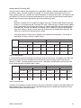
Continuous Red* . . . . . . . . . . . . . . . . . . . . . . . . . . . . . . . . . . . .
Flashing Display Alpha ("In-use")* . . . . . . . . . . . . . . . . . . . . . . . . . . .
Solid Red Talk LED & Flashing Display Alternating Pattern of Alpha & (-**-) ("Busy").
Flashing Display Alpha (on time equal to off time)* . . . . . . . . . . . . . . . . . .
Amber Talk LED . . . . . . . . . . . . . . . . . . . . . . . . . . . . . . . . . . . .
.
.
.
.
.
.
.
.
.
.
.
.
.
.
.
.
.
.
.
.
.
.
.
.
.
.
.
.
.
.
.
.
.
.
.
.
.
.
.
.
.
.
.
.
.
.
.
.
.
.
.
.
.
.
.
.
.
.
.
.
.
.
.
.
.
.
.
.
.
.
.
.
.
.
.
.
.
.
.
.
.
.
.
.
.
.
.
.
.
.
.
.
.
.
.
.
.
.
.
.
.
.
.
.
.
.
.
.
.
.
.
.
.
.
.
.
.
.
.
.
.
.
.
.
.
.
.
.
.
.
.
.
.
.
.
.
.
.
.
.
.
.
.
.
.
.
.
.
.
.
.
.
.
.
.
.
.
.
.
.
.
.
.
.
.
.
.
.
.
.
.
.
.
.
.
.
.
.
.
.
.
.
.
.
.
.
.
.
.
.
.
.
.
.
.
.
.
.
.
.
.
.
10-1
10-1
10-1
10-1
10-1
10-1
. 10-1
. 10-1
. 10-2
. 10-2
. 10-2
Glossary
11-1
Appendix
12-1
iv
S
E C T I O N
1
I NTRODUCTION
CHAPTER1
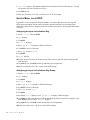
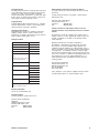
Description
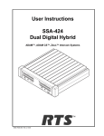
Figure 1.1 KP-632 keypanel front view.
Listen
Headset MENU
Talk
Vol. Sel.
FWD
Mic
------ ------ ------ ------ ------ -----KP-12
OKP4
ANDY12 KP-632 DAN
KP96
™
KP-632
BACK
1F0144 DAN456 SL0332 KP12-1 M00900
1
PL
AUTO
2
3
IFB
ISO
PREFIX
4
5
RELAY
TYPE
COPY CW
E-PNL
7
8
EX COPY
DISPLAY
6
9
MULT
Headset
MUTE CLR
Call waiting
Listen
5
------ ------ ------ WKP4-2 WKP4
NUM
SLIST
PHONE
0
PGM
FUNC
Vol.
1
4
3
2
Talk
The RTS™ Model KP-632/24 Keypanel mounts in a standard 19” equipment rack, is two rack
spaces high and has 24 lever keys: 22 keys for intercom talk/listen assignment; 1 key for call
waiting respond/clear; and 1 key for headset/microphone switching. The KP-632/24, like the
KP-32 keypanel, combines all of the programmable features of the KP-9X and KP-12 series of
keypanels. It adds significant new features such as digital signal processing and binaural headset
operation with lerft/right assignment of audio signals. The KP-632/24 introduces large LCD
displays with adjustable backlighting. These new displays allow for a total of 6 characters per key
which translates into more naming possiblities.
Features
• Large LCD displays that provide 6 characters per lever key. Provides good contrast with
adjustable backlighting over a wide range of light conditions.
• 24 lever keys, with 22 keys available for full Talk/Listen configuration. Keys support both
latching (hands-free) and momentary (push-to-talk) operation.
• Enhanced programming keypad. Provides the complete KP-9X keypand command subset, plus
new keypad commands and an extensive scrollable menu system. Menus include helpful
prompts to walk the user through setup.
• Only 90 mm deep behind the front panel (approximately 130 mm with connectors). Perfect for
consoles, OB vans, etc.
• Digital Signal Processing (DSP) Improves microphone voice activation and limiting. Adds
new mixing, metering and filtering capabilities.
• Binaural (5-pin) Headset Connector: Works with the DSP mixing feature. Lets you
independently assign intercom, mic, and program audio to left or right headphone. Note:
monaural (4-pin) connector available as an option. For monaural operation, the mixer lets you
select which items are monitored in the headphones.
1-1
• Upgradeable. Firmware updates can be received via the internet, for example, and then
downloaded to the KP-632 via the intercom connection. Firmware is available in both English
and Japanese Katakana character sets.
• Optional General Purpose Interface (GPI)/Connector module: Can be installed either in the
factory or in the field. Provides a variety of audio and logic inputs and outputs.
• Optional EKP-632 Expansion Panel: Provides additional Talk/Listen keys for a total of 48
Talk/Listen keys.
Options
GPI/Connector Module
Figure 1.2 KP-632 connector option board.
Provides connectors for two line-level audio inputs (program 1 and 2), an unswitched, balanced
microphone preamplifier output, an external headset, an external speaker output, and a foot
switch input (for remote switch activation of all "armed" talk keys, or just one key). Also includes
a General Purpose Input / Output (GPIO), with four opto-isolated inputs, two open-collector
outputs, and two SPDT relay outputs. Inputs can activate single keys, groups of keys, or change
setup pages. Outputs can activate external devices from keypanel keys or from GPI inputs.
Available factory installed or as an add-on kit.
CSI-100 Coaxial System Interface Module
Figure 1.3 KP-632 CSI-100 coaxial system interface board.
Provides the ability to link the unit to the matrix using a single 75 ohm coaxial cable. The
interface converts all audio and data streams to a single transmission path. Perfect for systems
where there are existing, but unused 75 ohm video cable. Requires a CSI-200 interface unit at the
intercom matrix end.
1-2
KP-632 User Manual
EKP-632 Expansion Keypanel
Figure 1.4 EKP-632 expansion keypanel front view.
Provides an additional 24 intercom keys.
LCP-632 Level Control Panel
Figure 1.5 LCP-632 level control panel front view
Provides easy adjustment of point-to-point and party line listen levels for individual intercom
keys. One LCP-632/16 adjusts one row of keys.
MCP-90 Panel Microphone
Part Number
MCP-90-3
MCP-90-8
MCP-90-12
MCP-90-18
Description
3” electret panel microphone
8” electret panel microphone
12” electret panel microphone
18” electret panel microphone
Headsets
Part Number
300852-202
300853-501
Description
PH-88R5 Single sided intercom
headset fitted with A5M
PH-44R5 Binaural intercom
headset fitted with A5M
1-3
1-4
KP-632 User Manual
S
E C T I O N
2
I NSTALLATION
CHAPTER2
Option DIP Switch Settings
Switch 1: Latch Enable/Disable
Default setting = Open: Enable.
Note
Description: An intercom key can always be turned on for momentary conversation by pressing
and holding the key during the conversation. There is also an electronic latching feature that lets
you tap intercom keys to turn them on or off. This permits convenient hands-free conversation.
However it can also result in a talk circuit being left on unintentionally. For example: A key that
talks to a public address system could be accidentally left on. Or an IFB key (a type of key
assignment that is often used by a director or producer to give instructions to a listener, such as a
news anchor during a television broadcast) could accidentally be left on, causing confusion for
the IFB listener. To prevent such accidents, the latching feature can be turned off.
DIP switch 1 disables latching for the entire keypanel. If you just need to disable latching for
selected keys, leave DIP switch 1 in the "Open" position. Then, disable latching for the desired
keys using the "D" check boxes in the Keypanels / Ports setup screen of ADAMedit.
Switch 2: Key Gain Enable / Disable
Default setting = Open: Enable.
Description: Enables or disables the Key Gain item in the Key Assign menu.
Switch 3: Screen Saver Enable / Disable
Default setting = Open: Enable.
With Screen Saver enabled, the KP-632 will shut off the display and enter a low-power state after
a few minutes of inactivity. The display reactivates instantaneously on incoming call or when the
keypanel operator actuates any control. As with all fluorescent and back-lit LCD displays, some
dimming will occur after many years of operation. Using the screen saver helps maximize the
display life.
2-1
Switch 4: Call Flash Timeout
Default setting = Open: 15 Second Flash.
Note
Description: Whenever there is an incoming call and there is a talk key assigned to the caller, the
talk LED next to that key will flash. The flash can be set for 15 second timeout, or until the
caller's talk key is released.
Future versions of ADAMedit and ZEUSedit will be able to override the Call Flash Timeout
setting.
Switch 5: Footswitch Enable / Disable*
Default = Open: Disabled.
Notes
Description: The optional Connector Module has a footswitch (GRP CALL) input. If the
footswitch is enabled (DIP switch 5 set to the "Closed" position), then keys that are latched on
will not activate until the footswitch is closed. Latched keys are indicated by winking green talk
LEDs (on time less than off time), and when the footswitch is activated, the LEDs provide the
normal talk-on indication.
1 If the talk key is held down in Footswitch mode the channel will be activated until the user
releases the key. The use of this function does not require the footswitch to be used.
2 If DIP switch 1 is set to the “Closed” position, nothing will latch.
3 Individual keys can be set to non-latching via ADAM Edit. If this is done, the footswitch has
no effect on the keys that have been set to non-latching. Please see ADAM Edit help for more
information.
Switch 6: Network Mode Selection
Default Setting: Open (Mode 1)
Description: In the Mode 1 setting, the keypanel functions operate as called out in the main
portion of this manual. If the switch is closed (Mode 2), then the functions operate as outlined in
this manual with slight modifications. Any function that is affected by Mode 2 operation will
have an asterisk (*) by it. The changes/modifications to the functionality is called out in the
section titled “Mode 2 Operation”
Switch 7: Test/Debug
Default Setting: Open.
Switch 8: Test/Debug
Default Setting: Open.
Address Switch Setting
General Information
In Zeus, ADAM CS, and ADAM Intercom Systems, intercom ports are arranged in groups of
eight. All ports in a group share a common data port. Each KP-632 keypanel is uniquely identified
on the data port by the setting of its Address switch. The method of determining the proper
Address switch setting varies for each intercom system. Use the method for your intercom system
as described below. Then set the white pointer on the Address switch to point to the correct
setting.
2-2
KP-632 User Manual
Address Setting for Zeus
Intercom port connectors on the Zeus back panel are arranged in three groups of eight intercom
ports. For each group, intercom port connectors are labeled ID 1, ID 2, etc. When you connect a
KP-632 keypanel to Zeus, set the Address switch to match the corresponding ID number on the
Zeus back panel. Note that address switch settings 0, and 9 through F are not used.
Address Setting for ADAM CS
Each Audio I/O card contains 1 group of 8 intercom ports. However, the method of breaking out
the groups depends on the type of connectors on the back panel.
ADAM CS with RJ12 or DB-9 back panel:
Note
The intercom port connectors are arranged in groups of 8. The first connector at the left for each
group is Address 1, the next is Address 2, and so forth.
Address switch settings 0, and 9 through F are not used.
2-3
Figure 2.1 Address number vs intercom port numbers for 8-Port Audio I/O Cards (ADAM AND ADAM
CS Intercom Systems.
ADAM CS with 50-pin Telco back panel:
Note
2-4
Determine the address setting from Figure 2.1. To use the table, locate the intercom port number
to which the KP-632 will be connected. Then, read across to the "Address" column to find the
Address number. Set the KP-632 Address switch to this number.
Settings 0, and 9 through F are not used.
KP-632 User Manual
Address Setting for ADAM
Each Audio I/O card contains 1 group of 8 intercom ports. Determine the address setting from
Figure 2.1. To use the table, locate the intercom port number to which the KP-632 will be
connected. Then, read across to the "Address" column to find the Address number. Set the KP632 Address switch to this number. Note: settings 0, and 9 through F are not used.
Connections
EXP. Connectors
Connect from the Exp. connector on the back of the KP-632 to the Expansion 1 connector of an
optional EKP-632 Expansion Panel. Use the interconnect cable supplied with the Expansion
Panel.
Frame Connector
Use either of the Frame connectors (but not both) to connect to an intercom port of the intercom
system. The intercom port you connect to should agree with the address that you set previously.
Cable wiring diagrams are shown in Figure 2.2 and Figure 2.3.
Figure 2.2 DE9S Intercom Cable Wiring
2-5
Figure 2.3 RJ12 Intercom Cable Wiring
Power Supply Connector
Align and insert the external power supply connector. Tighten the locking ring. Connect a power
cord to the power supply and to an AC power source. The power supply accepts 100-240 VAC,
50/60 Hz.
Note
At power-up, the alphanumeric displays will first show asterisks (******). After several seconds
to a minute the intercom key assignments will display.
If the keypanel cannot establish communication with the intercom system, all alphanumeric
displays will continue to show asterisks. Check the keypanel to matrix cable connection if this
occurs. If the keypanel loses communications with the intercom, it will not revert to ****’s for 30
seconds. Hence, if there is a short disruptionin the data communications, the panel will not show
******’s at all (although the panel my briefly display ------’s).
Headset Connector
A stereo headset may be connected for use along with or in place of the front panel speaker and a
separate microphone. Headphones may be connected for use with a separate microphone.
Headset Microphone Gain Adjustment
The gain of the headset microphone preamp output to the matrix can be adjusted via the recessed
trim pot located on the back panel. Turn the pot clockwise to increase gain and counter-clockwise
to decrease gain. The trim pot provides 40dB of adjustment range with a +16dBu maximum
output limit. The default factory default setting for this adjustment is +8dBu.
2-6
KP-632 User Manual
Panel Microphone Connector
A panel microphone may be connected for talking with either the front panel speaker or
headphones used for listening. The connector accepts MCP90 Panel Microphones. Insert the
microphone and rotate the entire microphone body several turns to lock in place.
Panel Microphone Gain Adjustment
The gain of the panel microphone preamp output to the matrix can be adjusted via the recessed
trim pot located on the back panel. Turn the pot clockwThe trim pot provides 40dB of adjustment
range with a +16dBu maximum output limit. The default factory default setting for this
adjustment is +8dBu.
2-7
This Page Left Blank Intentionally
2-8
KP-632 User Manual
S
E C T I O N
3
B ASIC O PERATION
CHAPTER3
Screen Saver Operation
Note
If the KP-632 is set for screen saver operation, the alphanumeric display automatically shuts off
after several minutes of inactivity. The display reactivates on incoming call or when the keypanel
operator actuates any control. DIP switch 3 turns enables/disables screen saver operation.
You can override the normal timeout period for screen saver operation and immediately place the
keypanel in screen saver mode. See "Service Menu, Disply Dim".
Selecting Headset or Speaker
Note
Tap the Headset / Vol. Sel. key downward. The Vol. Sel. display alternates between Headset and
Speaker with each key tap. The Headset LED lights when the headset is selected and is off when
the speaker is selected.
Future versions of ADAM Edit and Zeus Edit will be able to override the Headset or Speaker
setting.
Listen Volume Adjustments
Note
By default, the Vol. control adjusts the listen volume for the speaker or headset, whichever
appears in the Vol. Sel. display. The level of auxiliary program inputs 1 & 2 (if GPI/O board is
present and Aux inputs are enabled) and the level of incoming audio from the intercom matrix can
be adjusted. To adjust a level, press the Vol. Sel. button until the desired source appears in the
Vol. Sel. display (Aux1, Aux2, or Icom). Then, use the Vol. control to adjust the listen volume. The
Vol. control defaults back to the speaker or headset after about one minute of inactivity of the
control. The minimum volume level for either the keypanel speaker or headset may be adjusted.
See “Service Menu, Min Volume”.
You can save the volume adjustments to be the power-up defaults using "Service Menu, Save
Cfg".
3-1
Intercom Keys and Displays
Alphanumeric Display Indications for Intercom Keys
Upper Case Letters: Upper case letters indicate keys that have any kind of talk assignment, with
or without a corresponding listen assignment. Example: DIR1
Lower Case Letters: Lower case letters indicate keys that have only a listen assignment. Example:
dir1.
Dashes ------: Dashes indicate a key that has no talk or listen assignment.
Note
Flashing Alphanumeric Display: This means the key is activated to talk to an IFB, ISO, or TIF.
The flashing alphanumeric display for TIF keys, remote IFB keys, and remote ISO keys can be
disabled by placing a check mark next to "Don't generate tallies for TIF and trunk use" in
ADAMedit (Options menu, Intercom Configuration, Options tab).
LED Indications for Intercom Keys
Note
Future versions of ADAM Edit can override LED indications.
Talk LED Indications
The talk LED is the lower LED for each key. The talk LED indications are as follows:
Continuous Green*
Talk is on and the keypanel operator can be heard at the destination.
Continuous Red Talk LED & Flashing Display Alpha ("In-use")*
The key is off, but someone is talking to the destination. This indication is provided for any local
PL, IFB, ISO, or TIF key. It does not apply to remote IFB or ISO keys. This indication is provided
so keypanels operators know when critical director communications are occurring. If you activate
the key, either of two things will happen:
• If you activate the key and the talk LED turns continuous green, this indicates that you and the
other keypanel operator are both talking to the destination.
Note
• IFB keys only: If the talk LED flashes red when an IFB key is activated, this indicates that the
other keypanel has a higher IFB priority and you cannot talk at this time.
The red "in-use" indication for TIF keys can be disabled in ADAMedit: In the ADAMedit
Options menu, select Intercom Configuration, then click on the Options tab. Place a check mark
next to "Don't generate talliesfor TIF and trunk use". Be sure to send the change to the intercom
system. Note that this will also disable the flashing alpha display when talking to remote IFBs or
ISOs as previously described.
Flashing Red Talk LED & Flashing Display Alternating Pattern of Alpha & (-**-)
("Busy")
Note
3-2
You cannot talk at this time. This indication occurs when you activate a local IFB key that is
already in-use by a keypanel with a higher IFB priority. It also occurs when you activate any key
assigned to a remote destination, but there are currently no trunks available.
Flashing red is also the intended indication when attempting to talk to a remote IFB while
someone else with a higher trunk IFB priority is already talking. However, this will require
ADAM MC version later than 9.9.x and Trunk MC version later than 7.x.x. As of this writing,
these versions are not implemented. Regardless of the indication provided, you will not be heard
KP-632 User Manual
at the remote location if your keypanel has the lower trunk IFB priority. IFB trunk priorities are
set in ADAMedit. (Click the "KP" button on the ADAMedit toolbar to access Keypanels / Ports
setup, then click the "Edit" button, then click the "Advanced" tab. Enter the desired IFB priority in
the fields provided. Be sure to send the change to the intercom system.)
Flashing Green Talk LED & Display Alpha (on time equal to off time)*
Note
There is an incoming call from the destination assigned to the key. Activate the key to talk back.
The duration of incoming call flash is controlled by DIP switch 4 on the KP-632 back panel. See
"Option Switch Settings" for further information.
Winking Green Talk LED (on time less than off time)*
This indicates that a key is ready to talk (key is on), but requires external footswitch activation to talk.
Listen LED Indication
The listen LED is the upper LED for each key. The listen LED is green when listen is on.
Intercom Key Operation
Basic Intercom Key Operation
The "up" position of an intercom key activates listen (if assigned). The "down" position activates
talk (if assigned). If there is no talk assignment for an intercom key, the talk position of the key
will not activate. If there is no listen assignment, the listen position will not activate.
For momentary activation of a key press and hold the key. Then, release it when finished.
Note
For latching operation (if enabled) tap a key; it will turn on and remain on. Tap the key again to
turn it off when finished.
Latching may be turned off for the entire keypanel by setting DIP switch 1 on the KP-632 back
panel to the Closed position. Latching may be disabled for individual keys on a keypanel using
ADAMedit: Click the KP button on the ADAMedit toolbar to open the Keypanels / Ports setup
screen. Select the intercom port where the keypanel is connected. Place a check mark in the "D"
check boxes for any keys where you want to disable latching. Be sure to send your changes to the
intercom system.
Operation of Intercom Keys with Auto Functions
Note
Assignment of keys with auto functions is described in the programming sections that follow.
Descriptions of the auto functions are also contained in the Glossary.
Operation of keys with auto functions is as follows:
Talk + auto follow
Talk and listen can be activated separately. The listen assignment listens to whatever is assigned
to the talk key.
Talk + auto listen
Both talk and listen will activate when talk is activated.
Talk + auto mute
Listen will turn off when talk is activated.
3-3
Talk + auto reciprocal
Listen will always be on, and talk may be turned on or off.
Talk + auto table
Note
If an IFB talk key has an auto-table listen assignment, talk and listen can be independently
activated. The listen key listens to whatever is defined as the IFB Listen Source for the IFB that is
assigned to the talk key.
A full explanation of the auto-table feature is beyond the scope of this manual. For further
information, search for "IFB" in ADAMedit help, then read the topics "IFB Auto Table
Description" and "IFB Setup Procedures".
All Call Key
Activating the key will also activate all keys to the left of it (up to, but not including another allcall key).
Talk + DIM
Note
If a point-to-point key has the DIM function as a level 2 talk assignment, activating the key will
cause the crosspoint levels to diminish for any other intercom ports that are currently listening to
the same destination and that are in the same DIM table.
A full explanation of DIM tables is beyond the scope of this manual. For further information,
search for "dim table" in ADAMedit help.
Operation of Intercom Keys with Options
Group Option Keys
Activating the master key in a key group will activate all keys in that group according to each
key's individual key assignment. Activating a slave key will not affect any other keys in the
group.
Solo Key
Activating a key that has the solo option will cause all other keys to turn off until the solo key is
again turned off.
Operation of Intercom Talk Keys with the Speaker DIM Setting
Note
Activating any talk key will cause the speaker or headphone volume at this keypanel to diminish
by the amount specified in the Dim menu item on the Service menu.
Do not confuse this with the Talk+DIM auto function previously described. Talk+DIM affects the
speaker or headphones on other keypanels when a particular talk key is activated on this
keypanel. Speaker DIM affects the speaker or headphone level on this keypanel when any talk
key on this keypanel is activated.
Operation of Intercom Keys assigned to TIF Ports
Note
3-4
If an intercom key is assigned to talk to an intercom port that is designated as a TIF port in
ADAMedit, placing the key in the talk position will activate the KP-632 dialing menu. See
"TELEPHONE OPERATION" for further information.
You designate an intercom port as a TIF port by checking the "Port is TIF" check box in
ADAMedit. (In ADAMedit, click the "KP" button on the toolbar to access Keypanels / Ports
setup, then select the intercom port where the TIF s connected, then click the "Edit" button, then
KP-632 User Manual
click the "Advanced" tab. Place a check next to "Port is TIF". Remember to send the change to the
intercom system.)
Muting the Microphone
Tap the MUTE key upward to turn microphone muting on or off.
Note
The Vol. Sel. display alternates between Hdst and Mute (or between Spkr and Mute) while the
microphone is muted.
While muting is on, you cannot be heard on the intercom, or by anyone on the telephone, or by
any device connected to the mic preamp output of the optional connector module.
Call Waiting Operation
Occasionally, a keypanel may call, and there won't be a key assigned to talk back to that caller. In
this case, the caller's name will appear in the Call waiting window. Press down and hold the Call
waiting key to talk back.
To clear a name from the Call waiting window, tap "up" on the Call waiting key.
Note
If a second call is received in the Call waiting window while a caller name is already displayed,
the Call waiting LED will flash red. To answer the second call, tap "up" to clear the first name,
then hold the key down to talk to the second caller.
By default, only the names of callers who are not currently assigned to intercom keys will appear
in the Call waiting window. Alternatively, you can force all caller names to display in the Call
waiting window. This is controlled either by DIP switch 2 on the ADAM Master Controller card
or by the ADAMedit check box titled "Always stack callers in call waiting window". (ADAMedit
Options menu, Intercom Configuration, Options tab. Note: the setting in ADAMedit overrides the
DIP switch 2 setting on the Master Controller card.) If your intercom system has mostly
keypanels with alphanumeric displays, we recommend that you do not stack all callers in the Call
waiting window.
3-5
This Page Left Blank Intentionally
3-6
KP-632 User Manual
S
E C T I O N
4
TELEPHONE O PERATION
CHAPTER4
Note
Telephone operations require an optional TIF-951 / TIF-2000 Telephone Interface. Also, you
must first assign an intercom key to talk/listen to the TIF. We recommend a talk+auto listen
assignment.
Receiving A Phone Call
Note
When there is an incoming telephone call, the talk LED will flash red next to the KP-632 key that
is assigned to the TIF. Activate the key to answer the call.
The red flash for incoming TIF call is the default operation. Alternatively, a continuous-red talk
LED indication can be provided. This is accomplished by checking the check box "Don't generate
tallies for TIF or trunk use" in ADAMedit (Options menu, Intercom Configuration, Options tab).
Note that this check box also affects other tally indications. For further information, press the F1
key while viewing the ADAMedit Options tab settings. Under the topic "Don't generate tallies for
TIF or trunk use" click on the "see table" link to view a table containing information about
operation with and without tally indications.
DIALING AND HANGING UP USING KP9X KEYPAD
SEQUENCES
KP9X Keypad Hang-up Sequence
1 Turn off the TIF talk key. (Tap "down" to toggle talk off. The talk LED should be off.)
2 On the keypad, tap PHONE CLR.
3 Momentarily turn the TIF talk key on, then off. The TIF key talk and listen indicators will turn
Note
off and the TIF-951 / TIF-2000 "OFF" LED will activate.
You can use the hang up sequence to hang up the TIF even if you did not place or answer the call.
KP9X Manual dial sequence
1 Activate the TIF listen key. (Tap "up" to toggle listen on. The listen LED should be on.)
2 Make sure the TIF talk key is off (Talk LED off).
3 On the keypad, tap CLR PHONE PGM.
4-1
4 Activate the TIF talk key. The talk LED turns green, the "ON" LED at the TIF-951 / TIF-2000
activates, and you should hear dial tone at the KP-632.
5 Dial the telephone number. Digits scroll in the display above the TIF key.
6 When the far end answers, you can dial additional digits (to access a mail system or automated
response system, etc.). When finished dialing, momentarily turn off the TIF talk key to end
dialing mode (talk LED turns red).
7 Turn the TIF talk key back on for conversation.
8 To end the call:
1 Turn the TIF talk key off.
2 Tap PHONE CLR.
3 Tap the TIF talk key. The TIF key talk and listen indicators will turn off and the TIF-951 /
TIF-2000 "OFF" LED will activate. The TIF-951 / TIF-2000 is now ready for another call.
KP9X Redial Sequence
Note
The last dialed phone number is always stored at the TIF and over-writes any previously dialed
phone number. If several people have access to the TIF, redial may not produce the results that
you expect!
1 Tap the PHONE key to activate dialing mode.
2 Tap "up" on the TIF key to activate listen.
3 Tap CLR 0
0 . The last phone number will redial.
4 After the number has dialed, click the PHONE key to end dialing mode.
5 If the far end answers, tap "down" on the TIF key to activate talk.
6 Use the KP9X hang-up sequence when finished with the call.
KP9X Autodial Sequences
Note
Unlike the autodial operations using the KP-632 menu system, which store telephone numbers
locally within the KP-632, the KP9X autodial operations work with telephone numbers that are
stored at the TIF-951 / TIF-2000. The advantage to saving at the TIF-951 / TIF-2000 is that many
users can access a common set of stored telephone numbers. A disadvantage is that users can
easily over-write important telephone numbers. Also, telephone numbers at the TIF-951 / TIF2000 are stored in volatile memory and will be lost if the TIF-951 / TIF-2000 loses power.
Storing an Autodial Number in the TIF-951 / TIF-2000
1 Tap the PHONE key.
2 Tap the TIF talk key to latch it on.
3 Using the number keys on the keypad, dial the phone number that you want to store. The entire
Note
phone number sequence can have up to 30 digits.
To insert one or more pauses anywhere in the dialing sequence, enter CLR CLR 9 9 for each
pause. A pause may be required, for example, if you need to enter a digit to get an outside line and
your phone system requires a pause before continuing to dial. If you are using credit card dialing,
several pauses may also be required between the phone number and your personal access code.
4 After dialing the telephone number, click CLR PGM, then enter a two-digit number (01, 02,
etc. up to 32) that you will use as the autodial number.
4-2
KP-632 User Manual
5 After storing the autodial number, hang up using the KP9X hang-up sequence.
Dialing an Autodial Number Stored in the TIF-951 / TIF-2000
1 Tap the PHONE key to activate dialing mode.
2 Tap "down" on the TIF talk key to latch it in the on position.
3 Tap CLR followed by the autodial number (01, 02, etc.).
4 When finished dialing, click the PHONE key again to exit dialing mode.
5 Hang up using theKP9X hang-up sequence.
DIALING AND HANGING UP USING THE KP-632 DIALING
MENU
The dialing menu will only activate when talking to an intercom port that has the "Port is TIF"
check box activated in ADAMedit. (In ADAMedit, click the "KP" button to access the
Keypanels/Ports screen, then select the port where the TIF-951 / TIF-2000 is connected, then
click the "Edit" button, then click the "Advanced" tab. Place a check mark next to "Port is TIF".
Remember to send this change to the intercom system.)
Manual Dialing
1 Turn on the TIF talk key. ManualDial displays in the Call waiting window.
2 Tap the PGM key. Dial#? displays, and the dial tone should be audible in your speaker or
Note
Note
headset.
To hang up at any time after this point: tap the BACK key. Hang upwill display, then tap PGM.
While using the phone, any incoming intercom calls to the Call waiting window will go into the
call waiting stack. The caller names will not be displayed, but the Call waiting LED will flash red.
You may either hang up the phone and answer the intercom call, or continue with the phone call
and answer the intercom call afterward.
3 Dial the phone number. Digits appear in the Call waiting window as you dial. Dialing tones are
audible in the speaker or headset.
Note
4 If the far end answers, begin your conversation.
After the far end answers, you may dial additional digits (to retrieve voice mail, log onto an
automated answering system, etc.).
Note
5 If there is no answer, or to hang up when finished talking, tap the BACK key. Hang up
displays. Tap PGM to hang up.
Occasionally, you may receive intercom caller names in the Call waiting window while you are
talking on the phone. In this case, the dialing menu options will be cleared from the Call waiting
window, and the Hang up option won't be available. Instead of trying to reenter the menu system,
use the "KP9X Keypad Hang-up Sequence".
Redial
Turn on the TIF talk key. ManualDial displays in the Call waiting window.
Tap the ↓↓ key until Redial displays.
Tap PGM.
4-3
Note
If the far end answers, begin your conversation.
After the far end answers, you may dial additional digits (to retrieve voice mail, log onto an
automated answering system, etc.).
Note
5 If there is no answer, or to hang up when finished talking, tap the BACK key. Hang up
displays. Tap PGM to hang up.
Occasionally, you may receive intercom an intercom caller name in the Call waiting window
while you are talking on the phone. In this case, the dialing menu options will be cleared from the
Call waiting window, and the Hang up option won't be available. Instead of trying to reenter the
menu system, use the "KP9X Keypad Hang-up Sequence".
Autodial
Note
Autodial is only available after you have saved autodial numbers.
1 Turn on the TIF talk key. ManualDial displays in the Call waiting window.
2 Tap the ↓↓ key until Auto Dial displays.
3 Tap PGM.
4 Tap ↓↓ to select the desired autodial number, then tap PGM.
5 If the far end answers, begin your conversation.
Note
Note
4-4
After the far end answers, you may dial additional digits (to retrieve voice mail, log onto an
automated answering system, etc.).
6 If there is no answer, or to hang up when finished talking, tap the BACK key. Hang up
displays. Tap PGM to hang up.
Occasionally, you may receive an intercom caller name in the Call waiting window while you are
talking on the phone. In this case, the dialing menu options will be cleared from the Call waiting
window, and the Hang up option won't be available. Instead of trying to reenter the menu system,
use the "KP9X Keypad Hang-up Sequence".
KP-632 User Manual
S
E C T I O N
5
KP9X S ERIES KEYPAD P ROGRAMMING
CHAPTER5
Note
A summary of the keypad programming sequences is located at the back of the manual for quick
reference.
KEYPAD PROGRAMMING, DISPLAY REQUESTS
Display requests let you view information about the keypanel configuration. You can display
information by two methods: either by entering sequences on the programming keypad, or by
scrolling the names of display requests in the Call waiting window and then selecting the desired
display request. The scrolling method also gives you access to additional features that are not
available with the keypad sequences. The following paragraphs discuss these two methods.
Display Requests Using Keypad Sequences
All display request sequences start with FUNC DISPLAY.
Display Panel ID
FUNC DISPLAY 1 .
Note
This sequence displays the calculated port number. The calculation is based on the data group that
the keypanel is connected to, combined with the Address switch setting on the back of the
keypanel. Note that if the Address switch is incorrectly set, the wrong Panel ID will display.
For futher information about port address calculation, see the "Port" description in the Glossary.
Tap CLR to quit.
Display Level 2 Talk Key Assignments
FUNC DISPLAY 2 .
This sequence displays all level 2 talk key assignments for about 10 seconds. Lev2 displays in the
Call waiting window.
Tap CLR to quit.
Display Listen Key Assignments
FUNC DISPLAY 3 .
5-1
This sequence displays all listen key assignments for about 10 seconds. Lstn displays in the Call
waiting window.
Tap CLR to quit.
Display Setup Page Assignments
FUNC DISPLAY E-PNL
Currently, there are four setup pages available for each keypanel. Each setup page defines a set of
16 talk and listen key assignments. Most RTS keypanels have a maximum of 16 keys, so one
setup page is typically assigned to the main keypanel, and is referred to as the "Main" setup page.
Additional setup pages are assigned to any connected expansion panels, and are referred to as
"Expansion 1", "Expansion 2", etc.). Since the KP-632 requires 2 setup pages, it uses the main
page assignments and also one expansion page (Figure 5.1). The EKP-632 uses two additional
expansion pages.
Figure 5.1 Setup page usage for the KP-632 and EKP-632
When you enter the sequence FUNC DISPLAY E-PNL, the Call waiting window displays Mn-1
or Mn-2, etc. This indicates which setup page is currently being used at the "Main" position. After
a few moments X1-1, or X1-2, etc. displays. This indicates which setup page is currently being
used by expansion 1. Next, if there is an expansion panel connected, X2-1 or X2-2 etc. displays,
followed by X3-1 or X3-2 etc. to indicate the setup page usage for expansion 2 and expansion 3.
Note
Tap CLR to quit.
To change the setup page assignments, see "KEYPAD PROGRAMMING, ASSIGNING SETUP
PAGES".
Test Keys and Displays
FUNC DISPLAY 0
When you enter this sequence, all alpha-numeric displays show a % symbol. Pressing down on
any key (except the Headset / Vol. Sel. key) will cause OK to display. This verifies operation of
the key. Tapping up or down on the Headset / Vol. Sel. key will cause the display to cycle
through the available selections.
If latching is enabled, tapping up or down on any intercom key, or the Call waiting key, will cause
the corresponding red LED to light. This verifies latching operation and also that the each red
LED is OK.
Holding any key in the up or down position will cause the corresponding green LED to light. This
verifies operation of the green LEDs.
Note
5-2
Tap CLR to quit.
This sequence is similar to Service Menu, Test Panel, page 44, except that the service menu test
also lets you check the operation of the keypad buttons.
KP-632 User Manual
Tone Generator Activation (FUNC-DISPLAY-7)
FUNC DISPLAY 7
This sequence activates the keypanel's internal tone generator. You can use the tone generator to
check the audio send and receive paths to and from the matrix. For example, you can assign a talk
key on the keypanel to talk to itself. When you activate the talk key, you should be able to hear
the tone from the keypanel speaker or from a headset.
Note
To turn off the tone generator, press the CLR key.
The microphone input is turned off when the tone generator is active.
Display Requests Using Scrolling
The display requests described previously can also be accessed using scrolling. Scrolling also
offers several additional features. To use scrolling, tap FUNC DISPLAY followed by ↓↓ or
−− to scroll through the list of display requests. The display request names will appear in the
Call waiting window as follows:
ID PGM:
Displays the calculated port number. CLR to quit.
Lev2 PGM:
Displays level 2 talk assignments. CLR to quit.
Lstn PGM:
Displays listen assignments. CLR to quit.
Name PGM:
Displays crosspoints closed to this keypanel. CLR to quit.
Type PGM:
Displays level 1 talk key assignment types. CLR to quit.
Mtx
PGM: Displays matrix ID for all level 1 talk assignments. CLR to quit.
Tone PGM:
Turns on tone generator. CLR to quit and turn off tone generator.
Epnl PGM: Displays setup page assignments. Mn=KP-632 bottom row keys. X1=KP-632 top row
key. X2=EKP-632 bottom row keys. X3=EKP-632 top row keys.
Gain PGM: After selecting this item, tap up on any listen key with a point-to-point or party line
assignment. The current listen gain from this keypanel to the intercom port or party line displays
in the Call waiting window. Tap ↓↓ or − − to change the gain. CLR to quit. Use VRst PGM
to reset all gains.
VRst PGM:
Reset all port / party line gains to 0dB.
Asgn PGM: Displays a list of key assignments that are set up for this keypanel, but not currently
accessible. This includes talk level 1 assignments on setup pages that are not currently assigned,
and any key assignment that might be obscured by the call-waiting window. You can scroll
through the list using the ↓↓ − − keys. Then use the Call waiting key to talk to any of the
listed destinations.
Test PGM:
Vxxx:
Test keys and displays. CLR to quit.
Display keypanel firmware version. CLR to quit.
KEYPAD PROGRAMMING, ASSIGNING SETUP PAGES
1 Tap the E-PNL key.
2 Select one of the four setup pages: tap 1 , or 2 , etc.
3 Tap the PGM key.
4 Tap any key in the row of keys where you want to assign the setup page.
5-3
Notes
• The same setup page cannot be assigned in more than one place. If a setup page is already
assigned somewhere else, you must clear or change that assignment first. With the exception of
the main row assignment, you can clear any page assignment from a row of keys by entering
E-PNL 0 PGM, then pressing any key in the row.
• If you cannot change the setup page assignments for a particular keypanel, this feature may be
restricted in ADAMedit (Keypanels / Ports screen, Edit button, Setup tab, Setup Page Options).
• To display setup page assignments at any time, see "Display Setup Page Assignments".
KEYPAD PROGRAMMING, ASSIGNING INTERCOM KEYS
General
There are three methods to assign intercom keys with keypad programming. These methods are
summarized below and explained on the following pages.
• Key Assignment using Keypad Numeric Entry: Using this method, you enter the panel
number, party line number etc. that you wish to assign to a key. This method requires that you
know the number (not the name) of the port, party line etc. that you wish to assign. Since most
users do not have access to this information, this method of key assignment is not
recommended.
• Key Assignment by Copying an Assignment: Using this method, you can copy an assignment
from one key to another. You can also use this method to transfer an incoming call to a talk key
and/or listen key.
• Key Assignment using Alpha Scrolling: Using this method, you scroll through lists of alpha
names in the Call waiting window and select the name of the panel, party line etc. that you
want to assign. Then you copy that name to a key. If descriptive names have been assigned
(using the intercom system configuration software) alpha scrolling is easiest to use.
Assigning Keys Using Keypad Numeric Entry
Note
Each programming step must be completed within 4-5 seconds. Otherwise, the programming
sequence will automatically quit.
General Procedure
1 For talk level 2 assignment only: Tap 0
0 . Otherwise, skip this step.
2 Select the key assignment type:
NUM Intercom port.
PL Party line.
AUTO Auto function.
FUNC SLIST Special list.
FUNC IFB IFB
FUNC ISO Camera ISO
FUNC RELAY Relay or GPI output.
3 Auto function assignment only: Tap an additional number to select the desired auto function:
1 Auto listen (listen keys only)
2 Auto follow (listen keys only)
5-4
KP-632 User Manual
3 Auto mute (listen keys only)
4 Auto reciprocal (listen keys only)
5 All call (talk level 1 only)
6 DIM (talk level 2 only, for point-to-point key, must enter 00 first)
7 Auto table (listen only, when talk level 1 is an IFB assignment)
Note
4 Trunked intercoms only: (Skip when assigning auto functions or local key assignments.) Select
an intercom matrix (tap 1 , or 2 etc.).
Intercom system numbers are the numbers that appear in the "Icm" column in CStrunk when you
select "Names" or "Setup" from the Intercoms menu.
5 (Skip when assigning auto functions.) Tap one or more number keys to select the desired port
number, party line number, etc:
1 If the destination is in the local matrix, just enter the number.
2 If the destination is in a remote matrix, you must always enter exactly 3 digits for a port
number, or exactly 2 digits for anything else. For example, to assign port 1 you must enter
0 0 1 ; for party line 1 you must enter 0 1 .
6 Tap PGM.
Notes
7 Tap down on a key to assign talk. Tap up to assign listen.
• If a key will not accept an assignment, the destination that you are trying to assign may not be
scrolling enabled in ADAMedit. Or, the key that you are trying to assign may be restricted in
ADAMedit.
• Auto functions are always assigned in the local intercom system, even when used with keys
assigned to a remote intercom system. For example, you can program a talk key to talk to a
remote party line and then program the listen key using auto-listen on the local intercom.
Pressing the talk key automatically activates listening for the remote party line.
Programming Key Assignments Using Copy
There are two ways to copy key assignments: 1) you can copy a call from the Call waiting
window to a key; or 2) you can copy one key's assignment to another key.
Copying a Call from the Call waiting Window to a Key
1 While the caller's name is displayed in the Call waiting window, tap the COPY CW key.
2 Tap the key where you want to copy to. The name of the caller should appear in the display
Note
above the key.
If a key will not accept an assignment, the destination that you are trying to assign may not have
scrolling enabled in ADAMedit. Or, the key that you are trying to assign may be restricted in
ADAMedit.
Copying One Key Assignment to Another Key
1 Tap the FUNC key.
2 Tap the EX COPY key.
3 Press the talk or listen key from which you wish to copy.
4 Press the talk or listen key to which you wish to copy. The name of the key assignment should
appear in the display above the key.
5-5
Note
If a key will not accept an assignment, the destination that you are trying to assign may not have
scrolling enabled in ADAMedit. Or, the key that you are trying to assign may be restricted in
ADAMedit.
Programming Key Assignments Using Alpha Scrolling
Alpha scrolling lets you scroll through a list of names of ports, party lines etc. in the Call waiting
window. Once the desired name is displayed in the window, you can copy it to a key. There are
four scrolling modes: intercom, type, prefix and single-step. The following example demonstrates
their use.
Example: Assign a port to a key using the various scrolling modes.
1 If the port is located in a remote intercom system, tap FUNC −− or FUNC ↓↓ to enter
intercom scroll mode and scroll up or down the list of intercoms in the Call waiting window.
Otherwise, skip to step 2.
2 When the desired intercom system name is displayed, or when making an assignment in the
local intercom system, tap FUNC TYPE to activate type scroll mode.
3 Use the −− or ↓↓ keys to locate the desired type of communication. In this example, you
would scroll to "P-P".
Abbreviations for types of communication:
• P-P: Point-to-Point
• PL: Party Line
• IFB: IFB
• SPCL: Special List
• RLY: Relay or GPI output.
• ISO: ISO
Note
4 When the desired type of communication is displayed, press PGM to retrieve the requested list.
Pressing PGM also exits type scroll mode and places the keypanel in single-step scroll mode.
In some cases, "WAIT" may display briefly while the requested list is being retrieved. "N/A" may
display if there is no list. In this case, scrolling is disabled in ADAMedit for all destinations of the
selected type. For further information about scroll settings, search for keyword "scroll" in
ADAMedit help.
5 When the keypanel is in single-step scroll mode it may take a long time to scroll to the desired
name (this is particularly true of point-to-point lists). To speed up the process, you can use
prefix scroll mode. Prefix scrolling mode scrolls through a list in alpha-numeric order, but
displays only the first occurrence of each two-character prefix. For example, if your intercom
system had users CAM1, CAM2, CAM3, DIR1, DIR2; prefix scrolling would display CAM1
followed by DIR1. Once you locate a desired two-character prefix using prefix scroll, you can
switch back to single-step scrolling to make your final selection. Tap PREFIX to enter prefix
scroll mode, then use the −− ↓↓ keys to scroll. When you locate a name with the same first
two characters as the name you are looking for, tap the PGM key to return to single-step
scrolling mode.
Note
6 In single-step mode, use the −− ↓↓ keys to make your final intercom port selection.
If you cannot locate the destination that you are looking for, it may not have scrolling enabled in
ADAMedit.
7 Copy the selected port to a talk or listen key:
1 Tap COPY
5-6
KP-632 User Manual
2 Tap down on an intercom key to assign talk, or tap up to assign listen.
Clearing a Key Assignment
There are two ways to clear a key assignment:
Method 1: Clearing the Call waiting Window and Copying it to a Key
1 Clear the Call waiting window, if necessary, by tapping up one or more times on the Call
waiting key.
2 Tap the COPY CW key.
3 Tap the key that you want to clear. Tap up to clear listen, down to clear talk.
Note
If a key will not clear, it is probably restricted using the "R" check box in ADAMedit.
Method 2: Copying a Blank Key Assignment to the Key that You want
to Clear
1 Tap the FUNC key.
2 Tap the EX COPY key.
3 Tap an unassigned key.
4 Tap the key that you want to clear. Tap up to clear listen, down to clear talk.
Note
If a key will not clear, it is probably restricted using the "R" check box in ADAMedit.
5-7
This Page Left Blank Intentionally
5-8
KP-632 User Manual
S
E C T I O N
6
KP-632 M ENU S YSTEM
CHAPTER6
Note
A chart of the menu system is located at the back of the manual for quick reference.
MENU SYSTEM, MENU ACCESS
1 Clear all names from the Call waiting display (if not clear) by tapping "up" one or more times
on the Call waiting key.
2 Tap MENU to activate the menu system.
3 Press ↓↓ to scroll forward through the list of menus. Press − − to scroll back.
4 Tap FWD or PGM to enter a menu. Tap BACK to exit a menu.
5 Within a menu:
• Press ↓↓ or − − to scroll.
• Tap FWD or PGM to select an item.
• Tap BACK to cancel a selection or to go back to the previous menu level.
MENU SYSTEM, DISPLAY MENU
Use this menu to display information about the keypanel configuration.
Display Menu, Asgn Type
Displays the talk level 1 assignment types for all keys. Abbreviations for the key assignment
types appear in the alphanumeric displays as follows:
• P-P: Point-to-point talk key.
• PL: Party line talk key.
• IFB: IFB talk key.
• SPCL: Special list talk key.
• RLY (System relay): The key activates a GPI output at the intercom frame, or a relay output at
a UIO-256 or FR9528 frame.
• ISO: Camera ISO talk key.
• UPL: UPL resource key.
6-1
Note
• AC: All-call key.
For descriptions of the various key assignment types, see the "GLOSSARY".
Display Menu, Chans On
Displays an alpha list, in the Call waiting window, of all intercom ports that currently have talk
crosspoints closed to this keypanel. Chans On is typically used to locate an open mic or other
open audio source that needs to be shut off. The most likely cause is typically a talk key that has
been left on at some keypanel. In this case, use the ↓↓ and − − keys to scroll through the list
of names. You can then press the Call waiting key to ask the person at the other end to turn off
their talk key.
Display Menu, Key Groups
Use the ↓↓ or − − key to select Group 1, Group 2, etc. Then press FWD or PGM to display
the group. The talk and listen LEDs of the master key will be lit red and the talk and listen LEDs
for the slave keys will be lit green.
Display Menu, Key List
Displays and allows access to all the other assignments on the other keypanel pages that are not
currently showing in the keypanel display.
Display Menu, Level 2
Displays the talk level 2 assignments for all keys.
Display Menu, Listen
Displays the listen assignments for all keys.
Display Menu, Matrix
Displays the intercom system name for all talk level 1 key assignments. In non-trunked intercom
systems, the intercom system name is always LOCL (local). In trunked intercom systems,
intercom system names are created in CStrunk (Intercoms menu, Names.)
Display Menu, Panel ID
Panel ID displays the calculated port number that the keypanel is connected to. The calculation is
based on the data group that the keypanel is connected to, along with the Address switch setting
on the keypanel. If the Address switch is incorrectly set, the wrong Panel ID will display. Panel
ID also displays the port alpha in brackets if the port is not scroll restricted.
Display Menu, Version
Note
6-2
Displays the firmware version of the keypanel.
For firmware upgrades, contact your intercom system dealer. The KP-632 firmware can be
upgraded from ADAMedit. In ADAMedit Help, search for "firmware update".
KP-632 User Manual
MENU SYSTEM, KEY ASSIGN MENU
Use this menu to assign intercom keys, to adjust listen levels for point-to-point keys and party line
keys, and to assign setup pages.
General Procedure to use the Key Assign Menu
1 Clear the Call waiting window if necessary, by tapping upward one or more time on the Call
waiting key.
2 Tap Menu
3 Tap ↓↓ to scroll down to the Key Assign menu.
4 Tap PGM or FWD to enter the menu.
Note
If you do not have a trunking intercom system, skip to step 6.
5 Remote key assignment only (trunking systems only): If your intercom system is configured
for trunking, Matrix displays in the Call waiting window. You must select a remote intercom
matrix before assigning intercom keys to destinations in that matrix. You do not need to select
an intercom matrix if you are assigning keys in your own intercom system. Also, do not select
an intercom matrix if you are assigning auto functions or setup pages, or if you are changing
listen gains for remote point-to-point keys or remote party line keys. Select a matrix as follows:
1 Press FWD or PGM to access the Matrix list.
2 Press ¯¯ o r -- , to locate the desired matrix.
3 Press FWD or PGM to select a matrix. Wait may display while the scroll lists for that matrix
are loading.
6 Pt-to-Pt should now display in the Call waiting window (both for local and remote key
assignment). This is the list of available point-to-point key assignments. Press ↓↓ or −− to
select a different list as follows:
Pt-to-Pt:
Assign a key to talk/listen to another intercom port.
Party Line:
IFB:
Assign a key to talk/listen to a party line.
Assign a key to talk/listen to an IFB.
Spcl List:
Assign a key to talk/listen to a special list.
Sys Relay:
Assign a key to activate a relay or GPI output.
Camera ISO:
UPL Resrc:
Assign a key to talk/listen to an ISO.
Assign a key to activate a UPL resource.
Auto Func: Assign an auto function to a key. (If you select this item, skip the rest of this
procedure and go to "Key Assign Menu, Auto Func".)
Key Gain: Adjust the listen gain for a key that already has a point-to-point or party line
assignment. (If you select this item, skip the rest of this procedure and go to "Key Assign Menu,
Key Gain".)
Reset Vols: Restore the default listen level for keys that have a point-to-point or party line
assignment. (If you select this item, skip the rest of this procedure and go to "Key Assign Menu,
Reset Vols".)
Setup Page: Change the setup page assignments. (If you select this item, skip the rest of this
procedure and go to "Key Assign Menu, Setup Page".)
7 Tap PGM or FWD to select a list. In some cases Wait may display while the requested list is
uploaded from the intercom system.
6-3
8 When the requested list is displayed, press ↓↓ or −− , to locate the desired assignment.
9 Tap PGM or FWD to select the assignment.
10 Talk Lvl 1 should now display in the Call waiting window. Press ↓↓ or −− if necessary to
select a different option. Options are as follows:
• Talk Lvl 1: Assigns only talk level 1. Leaves the listen assignment as is.
• Listen: Assigns only listen. Leaves the talk assignment as is.
• Talk + AF: Assigns talk level 1, with auto-follow listen.
• Talk + AL: Assigns talk level 1, with auto-listen.
• Talk + AM: Assigns talk level 1, with auto-mute listen.
• Talk + AR: Assigns talk level 1, with auto-reciprocal listen.
• Talk Lvl 2: Assigns talk level 2.
If you attempt to assign talk level 2 to a key and there is no talk level 1 assignment, your
assignment will go on talk level 1.
11If you change the talk level 1 assignment for a key that also has a talk level 2 assignment, the
talk level 2 assignment will be erased.
12Tap PGM or FWD to select one of the previously listed items.
13 Tap Key should now display.
14Tap an available intercom key. Tap down for any kind of talk key assignment. Tap up for a
listen-only key assignment.
• If you assign any type of talk key, the assignment name will appear in the alphanumeric
display above the key.
• If you add a listen assignment to an existing talk assignment, the listen assignment will appear
briefly in the alphanumeric display to confirm the assignment. Then the talk assignment will
reappear.
• If you assign a key that is listen only, the assignment name will appear briefly in upper-case
letters, then will change to lower-case letters.
Note
This completes the key assignment procedure. Refer to any notes below regarding the various key
assignment types.
When reassigning keys remember to remove any Chime, Solo, or Key Group options if they will
not be needed for the new key assignment.
Key Assign Menu, Matrix
Matrix appears only for trunked intercom systems. You must select a remote intercom matrix
before assigning intercom keys to destinations in that matrix. You do not need to select matrix to
assign keys to destinations in your own matrix. You also do not need to select a matrix when
assigning an auto function to a key.
Key Assign Menu, Pt-to-Pt
Assigns a key that talks or listens to another intercom port. Note that some pt-to-pt destinations
may be non-keypanel devices that cannot activate talk and listen paths. Therefore, if you want full
communication, you may need to assign both talk and listen on the key.
6-4
KP-632 User Manual
Key Assign Menu, Party Line
Assigns a key that talks and/or listens to a party line. The key will have no effect until members
have been assigned to the party line in ADAMedit. Note that party lines members are usually nonkeypanel devices that cannot activate talk and listen paths. Therefore, if you want full
communication with the party line, you will need to assign both talk and listen on the key. If all
communications will normally be 2-way, you may wish to assign the key as Talk + auto listen.
Key Assign Menu, IFB
By default, all IFBs are restricted and you will see Not Availwhen you attempt to select this item.
To see IFBs you must check the appropriate Scroll Enable check boxes in ADAMedit.
Key Assign Menu, Spcl List
Assigns a key that talks and/or listens to a special list. The key will have no effect until members
have been assigned to the special list in ADAMedit. Note that some or all special list members
may be non-keypanel devices that cannot themselves activate talk and listen paths. Therefore, if
you want full communication with all members of the special list, you may need to assign both
talk and listen on the key.
Key Assign Menu, Sys Relay
Sys Relay refers to any of several types of control devices that can exist in the intercom system,
including:
• The 8 GPI outputs from an ADAM Frame (J11 on the XCP-ADAM-MC Breakout Panel).
• The 8 GPI outputs of an ADAM CS frame (J903 on the ADAM CS back panel).
• The relay outputs of an FR9528 Relay Frame (RELAY OUTPUTS connector on the FR9528
back panel).
• The 16 GPI outputs of a UIO-256 Universal Input/Output Frame (J5 on the UIO-256 back
panel).
Key Assign Menu, Camera ISO
By default, all ISOs are restricted and you will see Not Avail when you attempt to select this
item. To see ISOs you must check the appropriate Scroll Enable check boxes in ADAMedit.
Key Assign Menu, UPL Resrc
By default, all UPL resources are restricted and you will see Not Avail when you attempt to
select this item. To see UPL resources you must check the appropriate Scroll Enable check boxes
in ADAMedit. (In the ADAMedit System menu, select UPL Resources. Then enter check marks
in the appropriate Scroll Enable boxes.)
Key Assign Menu, Auto Func
1 Press FWD or PGM to select auto functions in the Key Assign menu. Then press ↓↓ o r −−
to locate the desired auto function as follows:
• AutoFollow (AF, for listen keys only)
• Auto Listn (AL, for listen keys only)
6-5
• Auto Mute (AM, for listen keys only)
• Auto Recip (AR, for listen keys only)
• All Call (AC, for talk level 1 only)
• Dim ( Dim Table function, for talk level 2 on point-to-point keys only)
2 Press FWD or PGM to select the desired auto function.
3 Tap Key displays. Tap an intercom key to assign the selected auto function. Tap up to assign all
Notes
auto functions except All Call or DIM. Tap down for All Call or DIM.
• If the assignment is successful, the abbreviation for the auto function will appear in the
alphanumeric display for that key. However, if you try to assign an auto function to a key that
already has that auto function assigned, the assignment will be ignored. The assignment will
also be ignored if scroll enable for auto functions has been disabled in ADAMedit, or if the key
you are trying to assign has been restricted in ADAMedit.
• You can tap CLR to exit and return to normal operation, or tap BACK to return to the auto
function menu and make more assignments.
• Trunked intercom systems: Do not select a matrix before assigning auto functions. All auto
functions are assigned using the local matrix menus.
• You do not need to run Save Cfg to store auto function assignments. These are stored in the
intercom system.
• For descriptions of the auto functions, see "GLOSSARY".
Key Assign Menu, Key Gain
Use this menu item to adjust the listen gains for point-to-point or party line keys. The key that you
want to adjust must already have a point-to-point or party line listen assignment.
1 Press FWD or PGM to select Key Gain in the Key Assign menu.
2 Tap Key displays. Tap "up" on the key that you want to adjust.
3 The current listen level displays in the Call waiting window.
4 Press ↓↓ o r −− to change the listen level.
5 You may tap additional point-to-point or party line keys to change their listen levels. Or, tap
Note
CLR to quit.
You do not need to run Save Cfg to store key gain changes. These are stored in the intercom
system.
Key Assign Menu, Reset Vols
Use this menu item to simultaneously reset gains for all point-to-point or party line keys.
1 Press FWD or PGM to select Reset Vols in the Key Assign menu.
2 Done displays. All key gains are now reset to the default level.
3 Tap CLR to quit.
Note
6-6
You do not need to run Save Cfg after resetting key gains. These settings are stored in the
intercom system.
KP-632 User Manual
Key Assign Menu, Setup Page
Use this menu item to change the setup page assignments on the KP-632 or EKP-632. One setup
page is used for the top row of keys, and another setup page is used for the bottom row.
1 Press FWD or PGM to select Setup Page in the Key Assign menu.
2 Page 1 displays.
3 Press ↓↓ o r −− to select any of the following:
Page 1:
Assign setup page 1 to the KP-632 or EKP-632.
Page 2:
Assign setup page 2 to the KP-632 or EKP-632.
Page 3:
Assign setup page 3 to the KP-632 or EKP-632.
Page 4:
Assign setup page 4 to the KP-632 or EKP-632.
Clear Page:
Clear a page assignment from the KP-632 or EKP-632.
4 Tap PGM.
5 Tap Key displays. Tap any key in the row where you want to assign the setup page. The key
assignments for that page should appear in the displays.
Note
6 You can press ↓↓ o r −− to select and assign another setup page. Or, tap CLR to exit.
You do not need to run Save Cfg to store changes to setup pages. These are stored in the intercom
system.
KEY OPTION MENU
Key Option Menu, Auto Dial
Use this menu item to store auto dial numbers.
1 Select Auto Dial, then tap PGM.
2 Phone#? displays.
3 Begin tapping number keys. The numbers will scroll in the Call waiting window.
Note
To insert a pause at any time, tap CLR 9
dialing 9 to get an outside line.
9 . For example, you may have to insert a pause after
4 Tap FWD. (Do not tap PGM!)
5 A-Dial #1 displays (store auto dial number 1). To store a different auto dial number, press ↓↓
or − − to select the desired auto dial number.
6 Tap PGM.
7 #XX saved displays (where XX = the auto dial number you selected).
8 Run Service Menu, Save Cfg, to store auto dial numbers.
Key Option Menu, Chime
You can add a chime tone to any key for incoming call announcement. The chime tone will
activate for about 5 seconds after a call is received.
1 Select Chime, then tap PGM.
6-7
2 Tap any keys where you want to add a chime tone. Both LEDs will light red for the selected
keys.
3 Tap CLR to exit.
4 Run Service Menu, Save Cfg, to store Chime settings.
Note
The chime option will continue on a key even if you change the key assignment.
Removing the chime option from a key
Repeat the procedure to add chime, but tap any keys where the LEDs are lit red to turn them off.
Run Save Cfg to store the changes.
Key Option Menu, Key Groups
You can set up a key group, so that when you activate one key (the master key) all keys in the
group will activate. Up to 4 key groups can be set up.
1 Select Key Groups, then tap PGM.
2 Group 1 displays. To select a different group, press ↓↓ or − − .
3 Tap PGM.
4 Tap Master displays. The master key is the key that you will press to activate the group.
5 Tap the intercom key that you want to use as the master. Both LEDs next to the key will light
red.
6 After you select the master key, Tap Slaves displays. Slave keys are the keys that will activate
along with the master key.
7 Tap one or more keys to select them as slave keys. Both LEDs will light green for each key that
is selected. You can tap a key again to remove it from the key group.
8 Tap CLR when finished.
9 Activating the master key should now cause it and all slave keys to activate. The LEDs for
each key will activate according to the current key assignment for that key.
10 Run Service Menu, Save Cfg, to store Key Group settings.
Note
Key group settings will continue on keys even if you change the key assignments.
Clearing a key group
1 Select Key Groups, then tap PGM.
2 Group 1 displays. To select a different group, press ↓↓ or −− .
3 Tap PGM.
4 Tap Master displays.
5 Tap the current master key. The LEDs will remain lit red.
6 After you tap the master key, Tap Slaves displays.
7 Tap all the keys where the LEDs are lit green. This will turn the LEDs off.
8 Tap CLR when finished.
9 The key group is now cleared.
10 Run Service Menu, Save Cfg, to store the cleared key group setting.
6-8
KP-632 User Manual
Key Option Menu, Solo
A solo key will cause all other keys to turn off when activated. You can assign one solo key.
1 Select Solo then tap PGM.
2 Tap Key displays.
3 Tap a key. Both LEDs for the key will light red to confirm the assignment. Tap the key again if
you made a mistake and want to remove the assignment.
4 Tap CLR when finished.
5 Activating the solo key should now cause all other activated keys to turn off. The keys will turn
back on again when you turn off the solo key.
6 Run Service Menu, Save Cfg, to store the Solo setting.
Note
The solo option will continue on a key even if you change the key assignment.
Removing the solo key option
1 Select Solo, then tap PGM.
2 The LEDs for the solo key will be lit red.
3 Tap the solo key to turn off the LEDs.
4 Tap CLR to exit.
5 The solo key is now cleared.
6 Run Service Menu, Save Cfg, to save the change.
SERVICE MENU
Service Menu, Aux Inputs
Enables or disables an AUX input audio path to any outputs.
1 Select Aux Inputs, then tap PGM.
2 Aux In 1 displays. To select Aux In 1 or 2, press ↓↓ .
3 Tap PGM.
4 →Enabled displays.To select enabled or disabled, press ↓↓. The arrow indicates that the input
is enabled.
5 Tap PGM
6 Tap CLR to exit when finished
7 The new Aux In assignment is now set.
8 Run Service Menu, Save Cfg, to store the Aux Inputs setting.
9 To assign the destination of the Aux Inputs, see the Mixing entry for “Service Menu, DSP
Func”.
Service Menu, Dim
This item causes the speaker or headphone level to diminish by a specified amount whenever a
talk key is activated.
6-9
1 Select Dim, then tap PGM.
2 Speaker displays. To select headset, press ↓↓ .
3 Tap PGM.
4 By default, -8dB displays for speaker, and 0dB displays for headset. This is the default amount
of dimming.
5 Press ↓↓ to increase the amount of dimming. Press −− .to decrease it.
6 Tap CLR to exit when finished.
7 The new dimming level is now set.
8 Run Service Menu, Save Cfg, to store the Dim setting.
Service Menu, Disply Dim
This item adjusts the alphanumeric display settings.
1. Select Disply Dim, then tap PGM.
2. Disply Off displays
3. Press ↓↓ or −− .to select any of the following:
Displ Off:
Turns off the display. Any incoming call, or control movement, will reactivate the
display.
Dim: Possibly a better choice when the ambient light level is low. Uses less power and increases
display life.
Normal:
Default medium brightness setting.
Bright:
Good when ambient light is bright.
Maximum: Recommended only for very bright ambient light, such as outdoors. Uses maximum
power and decreases display life.
Note
Scr Saver: Overrides the normal screen saver timeout period and immediately places the
keypanel in screen saver mode. Normal display operation resumes if there is an incoming call
or if the user actuates any control.
For settings which change the operating brightness, run Service Menu, Save Cfg, page 44, to store
the setting.
Service Menu, DSP Func
1 This item accesses the digital signal processing features.
2 Select DSP Func, then tap PGM.
3 Filtering displays. Press ↓↓ or −− .to display any of the following items:
Filtering
Gating
Metering
Mixing
4 Refer to one of the following paragraphs for further information on the item that you select.
6-10
KP-632 User Manual
Filtering
Filtering lets you add a 9.6 kHz notch filter to one or more audio sources. This can be useful in a
few cases when the keypanel data port signal is being heard in the audio line due to cable routing
problems.
1 Select Filtering, then tap PGM.
2 Microphone displays. Press ↓↓ or −− .to display any of the following items:
Microphone
Matrix
Aux 1
Aux 2
3 Tap PGM.
4 →None displays to indicate that no filtering is selected.
5 Press ↓↓.
6 Notch displays.
7 Press PGM.
8 →Notch displays. The arrow indicates that the notch filter is now selected.
9 Tap CLR to exit.
10 Run "Service Menu, Save Cfg", to save the change.
Gating
Gating minimizes or eliminates background noise problems by shutting off an audio source when
the sound level drops below a certain threshold.
1 Select Gating, then tap PGM.
2 Microphone displays. Press ↓↓ or −− .to display any of the following items:
Microphone
Matrix
Aux 1
Aux 2
3 Tap PGM.
4 Gating displays.
5 Tap PGM.
6 →Gating displays. The arrow indicates that gating is now selected.
7 Tap CLR to exit.
8 Run "Service Menu, Save Cfg", to save the change.
Metering
Metering lets you use the Vol. display as an LED bar graph meter to monitor an audio signal for
about 1 minute.
1 Tap PGM. Microphone displays. Press ↓↓ or −− .to display any of the following items:
Microphone
Matrix
Aux 1
Aux 2
6-11
2 Tap PGM.
3 Meter: Mic displays. Press ↓↓ or −− .to display any of the following items:
Meter: Mic
Meter: Mtx
Meter: Aux1
Meter Aux 2
4 Tap PGM.
5 The Vol. bar graph is now monitoring the selected audio source.
6 Tap CLR to exit metering, or allow the metering function to timeout after about 1 minute.
Mixing
Mixing lets you route selected audio signals to the intercom system, to the speaker, or to the left
or right headphone when using a headset. By default, the microphone signal is routed to the
matrix, and the matrix signal is routed to the speaker and to the left and right headphones.
1 Tap PGM.
2 To Matrix displays. Press ↓↓ or −− .to display any of the following items:
To Matrix
Speaker
Left Hdst
Right Hdst
3 Tap PGM.
4 →Mic or Mic displays. If an arrow displays, this indicates that the mic signal is currently being
routed to the destination that you selected in step 2. To toggle the selection, press PGM. You
can also press ↓↓ or −− .to display and toggle any of the following items:
Mic
Matrix
Aux 1
Aux 2
5 Tap CLR to exit when you are finished changing the mixing selections.
6 Run Service Menu, Save Cfg, to store any mixing changes.
Service Menu, Hdst Sel
This item lets you select either the front panel headset jack or the headset connector on the
optional rear connector module. By default, the front panel jack is selected.
1. Select Hdst Sel, then tap PGM.
2. →Default displays. The arrow indicates the default front panel jack is selected.
3. To change the selection, press ↓↓ .
4. External displays.
5. Tap PGM.
6. →External displays. This indicates that the rear panel jack is now selected.
7. Tap CLR to exit.
8. Run Service Menu, Save Cfg, to store the new setting.
6-12
KP-632 User Manual
Service Menu, LCD Bright
This item allows you to adjust the brightness of the LCD backlighting so that the unit’s display
can be viewed in a wide range of ambient room light conditions.The All selection controls the
overall LCD brightness level including the right LCD on the KP-632. The Main selection controls
the left LCD on the KP-632. The EXP1 controls the LCD on the EKP-632. Normally the LCD
brightness levels are balanced at the factory before shipping, thus under normal circumstances the
All selection should be used.
1 Select LCD Bright, then tap PGM.
2 All displays. To change the selection, press ↓↓ or −− to move through the All, Main, and
EXP1 selections.
3 Tap PGM.
4 If the All selection was made proceed to step 6. If Main was selected Left will appear. If EXP1
was selected press ↓↓ or −− to move through the Left and Right selections.
5 Tap PGM.
6 Value: X displays where x is a number between 5 and 100.
7 To change the selection, press ↓↓ or −−. The higher the number, the brighter the backlight.
8 Tap PGM.
9 Tap CLR to exit.
10 Run Service Menu, Save Cfg, to store the new setting.
Service Menu, LCP-632
By default, each LCP-632 that you connect to the KP-632 takes control of level adjustment for the
first available group of 16 physical keys that it finds. The first LCP-632 adjusts keys 1-12, which
corresponds to the bottom row of keys on the KP-632; the second LCP-632 adjusts keys 13-24,
and so forth (Figure 6.1). If you do not want to use an LCP-632 with certain keys, you must
program the KP-632 to skip those keys.
Figure 6.1 LCP-32 correspondance to KP-32 and EKP-32
For example, you may not want to use LCP-632s with the KP-632 but do want to use them with
an EKP-632. In this case, you must turn off LCP usage for keys 1-24 as follows:
1 Select LCP-632, then tap PGM.
2 1-12: Yes displays. This indicates that the first connected LCP-632 will attach to keys 1-12.
3 Tap PGM.
4 1-12: Skip displays. This indicates that the first connected LCP-632 will skip keys 1-12 and
will attach to the next available row of keys.
5 Tap ↓↓ to display 13-24: Yes.
6 Tap PGM.
6-13
7 13-24: Skip displays. This indicates that the first connected LCP-632 will skip keys 13-24 and
will attach to the next available row of keys.
8 Tap CLR to exit.
9 Run "Service Menu, Save Cfg", to store the new LCP-632 settings.
Service Menu, Local GPIO
If your KP-632 has an optional Connector Module, you can use this menu item to assign the
GPIO inputs and outputs. Inputs can be assigned to activate intercom keys (including group
master keys and a solo key). Outputs can be activated by intercom keys. Set up inputs and outputs
as follows:
Assigning an Input to Activate a Key
1 Select Local GPIO, then tap PGM.
2 Input displays.
3 Tap PGM.
4 GPI Inp #1 displays.
5 Press ↓↓ or −− .to display a different GPI input.
6 Tap PGM to select a GPI input.
7 Press ↓↓ to select Talk Key.
8 Tap PGM.
9 Tap Key displays.
10 Tap the intercom key that you want to assign. This is the key that will activate when the GPI
input activates.
11 Tap CLR to exit, or BACK to back up and make more assignments.
12 Run Service Menu, Save Cfg", to store local GPIO settings.
Assigning an Input to Activate a Key Group
1 Select Local GPIO, then tap PGM.
2 Input displays.
3 Tap PGM.
4 GPI Inp #1 displays.
5 Press ↓↓ or −− to display a different GPI input.
6 Tap PGM to select a GPI input.
7 Press ↓↓ to select Group.
8 Tap PGM.
9 By default, Group 1 displays. Press ↓↓ or −− .to display a different group.
10 Tap PGM. An arrow will appear to indicate that the group is now selected. For example, if you
press PGM to select Group 1, →Group 1 displays.
11 Tap CLR to exit, or BACK to back up and make more assignments.
12 Run Service Menu, Save Cfg, to store local GPIO settings.
6-14
KP-632 User Manual
Removing an Input Assignment
1 Select GPIO, then tap PGM.
2 Press ↓↓ or −− if necessary to select Input.
3 Tap PGM.
4 Press ↓↓ or −− .to display the GPI input that you want to remove.
5 Tap PGM.
6 Press ↓↓ to select Not Asgnd.
7 Tap PGM.
8 →Not Asgnd displays. The arrow indicates that "Not Assigned" is the new selection.
9 Tap CLR to exit.
10 Run Service Menu, Save Cfg, to store local GPIO settings.
Adding or Removing a GPI Output Key Assignment
1 Select Local GPIO, then tap PGM.
2 Input displays.
3 Press ↓↓ to display Output.
4 Tap PGM.
5 GPI Out #1 displays.
6 Press ↓↓ or −− to display a different GPI output.
7 Tap PGM to select a GPI output.
8 Tap Key displays. Also, if there is a key currently assigned to activate the selected GPI output,
both LEDs for that key will be lit red. If there is no assignment, no LEDs will be lit red.
9 Tap an intercom key to add or remove the GPI output assignment.
10 Tap CLR to exit, or BACK to back up and make more assignments.
11 Run Service Menu, Save Cfg, to store local GPIO settings.
Service Menu, Matrix Out
This menu item allows the user to select between Normal or Hot Mic. In the Normal (defualt)
setting audio from the Mic goes out to the Matrix when the talk key is latched. In the Hot Mic
setting audio from the Mic goes out to the Matrix with out regard to the talk key’s state.
1 Select Matrix Out from the Service Menu, then tap PGM.
2 →Normal displays
3 Press ↓↓ to select either Normal or Hot Mic
4 Tap PGM
5 Tap CLR to exit
6 Run Service Menu, Save Cfg, to store Matrix Out settings.
6-15
Service Menu, Mic Select
This menu item allows the user to select between the Panel and Headset Mic. In the Normal
(defualt) setting, audio from the Panel Mic used. In the Hdst Only, setting audio from the Headset
Mic is used.This is used to force the use of the headset microphone even when the keypanel’s
speaker is being used.
1 Select Mic Select from the Service menu, then tap PGM.
2 →Normal displays
3 Press ↓↓ to select either Normal or Hdst Only
4 Tap PGM
5 Tap CLR to exit
6 Run Service Menu, Save Cfg, to store Mic Select settings.
Service Menu, Min Volume
This menu item allows the user to set the minimum volume level for both the keypanel speaker
and the headset speaker(s). This is the minimum volume level available on the volume control
located on the front panel of the KP-632.
1 Select Min Volume from the Service menu, then tap PGM.
2 →Speaker displays
3 Press ↓↓ to select either Speaker or Headset
4 Tap PGM
5 Press ↓↓ or −− to increase or decrease the minimum volume level. The range is -24 dB to
-60 dB or full Mute.
6 Tap PGM
7 Tap CLR to exit
8 Run Service Menu, Save Cfg, to store Min Volume settings.
Service Menu, Mod Assign
Note
Normally, this is a service adjustment that is required only when replacing a key and display
module. It may also be required if for some reason, the key assignments, as displayed in
ADAMedit, appear to be in the wrong positions on the keypanel or expansion panel.
The KP-632 and EKP-632 use module ID numbers (Mod ID numbers) to define the address of
each key and display module. See Figure 6.2. By default, Mod 1 is always assigned to the right
half of the KP-632 and this never changes, since this module has the keypad and is unique.
However, the rest of the modules are identical. When replacing any of these modules, you may
have to reset the Mod ID number as follows:
1 Select Mod Assign from the Service menu and tap PGM.
2 Cancel? displays. To exit the procedure without making changes, tap PGM.
3 All of the alphanumeric displays, except Mod 1, will appear as shown in Figure 6.2. Assign the
Mod IDs as shown in the figure. Repeat the procedure for each module.
6-16
KP-632 User Manual
Figure 6.2 Mod ID assignments for the KP-632 and EKP-632.
Note
You do not need to run Save Cfg after changing Mod assignments.
Service Menu, Output Level
Allows the adjustment of the nominal audio output level to the matrix from 0 dB to +8 dB.
1 Select Outp Level, then tap PGM.
2 +8 dB displays.
3 −−decreases the level.
4 ↓↓ increase the level.
5 Tap PGM.
6 Tap CLR to exit.
7 Run Service Menu, Save Cfg, to store the Output Level settings.
Service Menu, Preamp Out (GPI Option Only)
Allows the user to choose how audio is routed to the Preamp Output connector. When Switched is
chosen, keypanel audio is routed to the preamp output connector when a talk key is latched. When
Hot Mic is chosen, audio is always available at the preamp output connector. When Disabled is
chosen, keypanel audio is isolated from the preamp output connector.
1 Select Preamp Out, then tap PGM.
2 →Switched displays.
3 ↓↓ toggles between Switched, Hot Mic, and Disabled.
4 Tap PGM.
5 Tap CLR to exit
6 Run Service Menu, Save Cfg, to store the Preamp Out settings.
6-17
Service Menu, Reset Cfg
Reset Cfg restores all custom settings to the defaults and erases all stored autodial numbers.
Service Menu, Save Cfg
Save Cfg PGM saves custom settings that you have made in the Key Option or Service menus.
made in the After customizing settings in the Key Option and Service menus, run Save Cfg to
store your custom settings in non-volatile memory. This will assure protection of you settings
when the keypanel is powered down. To erase all custom settings, run Service Menu, Reset Cfg.
Service Menu, Sidetone
PGM lets you adjust the level of you own voice heard in the headphones when using a
headset. Most people prefer some amount of sidetone to overcome the muffled sensation when
talking, especially when wearing a full-muff headset. The maximum level is 0 dB.
Sidetone
Service Menu, Test Panel
Test Panel
PGM lets you check the operation of all key and displays.
All alpha-numeric displays show a % symbol. Pressing down on any key (except the Headset /
Vol. Sel. key) will cause OK to display. This verifies operation of the key. Tapping up or down on
the Headset / Vol. Sel. key will cause the display to cycle through the available selections.
If latching is enabled, tapping up or down on any intercom key, or the Call waiting key, will
cause the corresponding red LED to light. This verifies latching operation and also that the each
red LED is OK.
Holding any key in the up or down position will cause the corresponding green LED to light. This
verifies operation of the green LEDs.
Tapping any keypad button (except CLR) will cause the keypad button name to appear in the Call
waiting window. This verifies operation of the keypad buttons.
Tap CLR to quit.
Service Menu, Tone Gen
Tone Gen PGM turns the KP-632 tone generator on or off. You can use the tone generator to
check the audio path from the keypanel to the matrix and back.
Note
6-18
Tap CLR to quit.
The microphone is muted when the tone generator is active.
KP-632 User Manual
S
E C T I O N
7
S PECIFICATIONS
CHAPTER7
Microphone Preamplifier
Panel Mic (Electret) Input Level:
-42 dB, 150 ohms @ 1 kHz
Headset Mic (Dynamic) Input Level:
-50 dBm, 150 ohms@ 1 kHz
Output Level (to matrix):
+8 dBu, ± 0.2 dBu
Max Voltage Gain, Mic to Line:
70 dB, ± 2 dB
Frequency Response:
100 Hz to 10 kHz, ± 2 dB
Limiter:
8 dB above nominal
Tone Generator
Output Level (to matrix):
+8 dBu ± 2 dBu
Output Frequency:
500 Hz
Headphone Amplifier
Maximum Voltage Gain:
10 dB
Frequency Response:
100 Hz to 10 kHz, ± 2 dB
Headphone Impedance:
8 to 600 ohms
Output Power:
300 mW into 50 ohms
Output Voltage Level:
8 volts peak-to-peak (max.)
Sidetone Range:
25 dB or mute
Speaker Amplifier and Speaker
Maximum Voltage Gain:
25 dB
Frequency Response:
100 Hz to 10 kHz, ± 2 dB
Output Power (per amplifier):
4 watts into 4 ohms
Output Voltage Level:
12 volts peak-to-peak (max.)
7-1
Volume Control Range:
52 dB
Speaker Rating:
4 watts max
Intercom Balanced Line Input/Output
Input Level:
Nominal: +8 dBu. Peak: ± 20 dBu max.
Input Impedance:
22k Ohms
Output Level:
+8 dBu, ± 2 dBu nominal
Output Impdeance:
60 Ohms
External Balanced Line Input: (Program Input)
Input Level
+8 dBu nominal
General
AC Supply:
External, switching type, 100-240 VAC, 50/60 Hz with locking DIN connector for attachment to
the keypanel and universal IEC connector for connection to various AC mains cords
Environmental:
Storage:
-40°C to +60°C
Operating:
-10°C to +41°C
Dimensions:
19" wide x 2RU x 3.5" (90 mm) deep
Approvals:
UL, CSA, VDE, CE
Connectors (Other connector options available)
Panel Microphone Connector (Electret)
Type:
3-circuit, 1/4" phone jack w/threaded metal bushing,
compatible w/ RTS MCP5/6
Pin-out:
Tip: +Audio and DC bias
Ring: Common
Sleeve: Chassis ground
Headset Connector (Dynamic)
Type:
7-2
KP-632 User Manual
XLR5 female
Pin-out:
Pin 1: Mic low
Pin 2: Mic high
Pin 3: Common
Pin 4: Headphone left high
Pin 5: Headphone right high
Power Input Connector
Type:
5-pin locking DIN
Pin-out:
Pin1: Common
Pin2: Common
Pin3: +5VDC, 1.50A Max.
Pin4: -15VDC, 0.150A Max.
Pin5: +15VDC, 0.5A Max.
Intercom Connectors: Parallel-wired DE9S and RJ12
Connectors
Type:
DE9S
Pin-out:
Pin 1: Data +
Pin 2: Data Pin 3: Audio in (from matrix) shield
Pin 4: Audio out (to matrix) +
Pin 5: Audio out (to matrix) Pin 6: Data shield
Pin 7: Audio in (from matrix) Pin 8: Audio in (from matrix) +
Pin 9: Audio out (to matrix) shield
Type:
RJ12
Pin-out:
Pin 1: Data Pin 2: Audio in (from matrix) +
Pin 3: Audio out (to matrix) +
Pin 4: Audio out (to matrix) Pin 5: Audio in (from matrix) Pin 6: Data +
Expansion Connector
Type:
RJ45
7-3
LCP Connector
Type:
RJ45
GPI Module Conntectors (Optional)
Aux 1 In (Auxiliary program input 1)
Type:
3-pin female XLR
Pin-out:
Pin 1: Ground
Pin 2: Input +
Pin 3: Input -
Aux 2 In (Auxiliary program input 2)
Type:
3-pin female XLR
Pin-out:
Pin 1: Ground
Pin 2: Input +
Pin 3: Input -
Notes
Balanced input, +8dBu nominal
Relay 1 & 2 Out
Type:
9-pin male D-Sub
Pin-out:
Pin 1: NC contact 1
Pin 2: COM contact 1
Pin 3: NO contact 1
Pin 4: NC contact 2
Pin 5: COM contact 2
Pin 6: NO contact 2
Pin 7: +5 VDC
Pin 8: Ground
Pin 9: +5 VDC
Relay 3 & 4 Out
Type:
9-pin male D-Sub
Pin-out:
Pin 1: NC contact 3
Pin 2: COM contact 3
Pin 3: NO contact 3
Pin 4: NC contact 4
Pin 5: COM contact 4
7-4
KP-632 User Manual
Pin 6: NO contact 4
Pin 7: +5 VDC
Pin 8: Ground
Notes
Pin 9: +5 VDC
The relay 1 and 2 contacts are electrically separate, but operate in unison. The relay 3 and 4
contacts are electrically separate, but operate in unison. The +5 VDC pins are connected
internally through 1K resistors to +5 VDC and can source 5 mA. This voltage can be used with
the relay contacts to create an active high output for some devices that require a +5 VDC signal to
activate. For example, connecting pin 7 to pin 3 of the Relay 1&2 connector will result in +5
VDC on pin 2 when the relay is activated.
Opto 1-4 In (Opto-isolated control inputs)
Type:
9-pin male D-Sub
Pin-out:
Pin 1: Input 1 Gnd
Pin 2: Input 2 Gnd
Pin 3: Input 3 Gnd
Pin 4: Input 4 Gnd
Pin 5: Gnd
Pin 6: Switch contact input 1
Pin 7: Switch contact input 2
Pin 8: Switch contact input 3
Note
Pin 9: Switch contact input 4
A contact closure between any switch input and ground will activate that input. The switch
contact inputs are also connected internally through 1K resistors to internal +5 VDC and can
source 5 mA for use with an external transistor switch circuit.
OC 1 & 2 Out (J2)
Type:
9-pin male D-Sub
Pin-out:
Pin 1: Gnd OC1
Pin 2: Emitter OC1
Pin 3: Collector OC1
Pin 4: Gnd OC2
Pin 5: Emitter OC2
Pin 6: Collector OC2
Pin 7: 5 VDC
Pin 8: No connection
Pin 9: 5 VDC
Headset (External headset connector)
Type:
9-pin male D-Sub
7-5
Pin-out:
Pin 1: Gnd
Pin 2: N/A leave unconnected
Pin 3: N/A leave unconnected
Pin 4: N/A leave unconnected
Pin 5: Balanced dynamic mic input +
Pin 6: Gnd
Pin 7: Headset Listen Out Left
Pin 8: Headset Listen Out Right
Note
Pin 9: Balanced dynamic mic input Mic input -60 dBu nominal. Headset out 0.325 watts into 8 ohms.
Foot Switch/Speaker
Type:
9-pin male D-Sub
Pin-out:
Pin 1: Gnd
Pin 2: Speaker Minus (-)
Pin 3: Gnd
Pin 4: No connection
Pin 5: Foot Switch
Pin 6: Speaker Plus (+)
Pin 7: No connection
Pin 8: No connection
Note
Pin 9: Gnd
A switch contact closure from the footswitch input to ground will activate the footswitch input.
MIC In (J7) Balanced Microphone Output
Type:
3-pin female XLR
Pin-Out:
Pin 1: Shield (circuit common)
Pin 2: DC bias and Audio Plus (+)
Pin 3: GND
Note
Input level -42.5 dBu nominal.
MIC Out (J8) Balanced Microphone Output
Type:
3-pin male XLR
Pin-out:
Pin 1: Shield (circuit common)
Pin 2: Audio output +
Note
7-6
Pin 3: Audio output Output level +8 dBu nominal (balanced).
KP-632 User Manual
S
E C T I O N
8
KP9X KEYPAD S EQUENCE Q UICK
R EFERENCE
CHAPTER8
KP9X DISPLAY SEQUENCES
FUNC DISPLAY 0 . Diagnostics mode.
FUNC DISPLAY 1 . Display port number.
FUNC DISPLAY 2 . Display level 2 talk assignments.
FUNC DISPLAY 3 . Display listen assignments.
FUNC DISPLAY -8 Display setup page assignments.
FUNC DISPLAY
ID PGM:
↓↓ or − − to select items as follows:
Display the calculated port number. CLR to end.
Lev2 PGM:
Display level 2 talk assignments. CLR to end.
Lstn PGM:
Display listen assignments. CLR to end.
Name
PGM: Display crosspoints closed to this keypanel. CLR to end.
Type PGM:
Mtx
Display level 1 talk key assignment types. CLR to end.
PGM: Display matrix ID for all level 1 talk assignments. CLR to end.
Tone PGM:
Turn on tone generator. CLR to end.
Epnl PGM: Display setup page assignments. Mn=KP-632 top row
key. X2=EKP-632 top row keys. X3=EKP-632 bottom row keys.
Gain PGM:
VRst
Port / party line listen gain. Turn on listen key. ↓↓ or − − to change gain.
PGM: Reset all port / party line gains to 0dB.
Asgn PGM:
Test
keys. X1=KP-632 bottom row
Display key assignments that are not currently accessible.
PGM: Test keys and displays. CLR to end.
Vxxx :
Display keypanel firmware version. CLR to end.
KP9X SETUP PAGE ASSIGNMENT
1 Tap E-PNL.
2 Select a setup page: tap 1 , or 2 , etc.
8-1
3 Tap PGM.
4 Tap any key in top row to assign page to top row. Tap any key in bottom row to assign page to
bottom row.
KEY ASSIGNMENTS USING KEYPAD NUMERIC ENTRY
1 For talk level 2 assignment only: Tap 0
0 .
2 Select the key assignment type:
NUM Intercom port.
PL Party line.
AUTO Auto function.
FUNC SLIST Special list.
FUNC IFB IFB
FUNC ISO Camera ISO
FUNC RELAY Relay or GPI output.
3 Auto function assignment only: Tap an additional number to select the desired auto function:
1 Auto listen
2 Auto follow
3 Auto mute
4 Auto reciprocal
5 All call
6 DIM (talk level 2 only, for point-to-point key)
7 Auto table (use only with IFB)
4 Trunked intercoms only: Select an intercom matrix (tap 1 , or 2 etc.).
5 Tap one or more number keys to select the desired port number, party line number, etc:
6 If the destination is in the local matrix, just enter the number.
7 If the destination is in a remote matrix, you must always enter at least 3 digits, so for example
to assign port 1 you must enter 0 0 1 .
8 Tap PGM.
9 Tap down on a key to assign talk. Tap up to assign listen.
KP9X PHONE OPERATION
KP9X Hang-up Sequence
1 Turn off the TIF talk key.
2 On the keypad, tap PHONE-CLR.
3 Turn the TIF talk key on, then off. The TIF key talk and listen indicators will turn off and the
TIF-951 / TIF-2000 "OFF" LED will activate.
8-2
KP-632 User Manual
KP9X Dial Sequence
1 Activate the TIF listen key (listen LED green).
2 Make sure the TIF talk key is off (Talk LED off).
3 On the keypad, tap CLR-PHONE-PGM.
4 Activate the TIF talk key (talk LED turns green). The "ON" LED at the TIF-951 / TIF-2000
will activate, and you should hear dial tone at the KP-632.
5 Dial the telephone number. Digits scroll in the display above the TIF talk key.
6 When the far end answers, you can dial additional digits (to access a mail system or automated
response system, etc.). When finished dialing, momentarily turn off the TIF talk key to end
dialing mode (talk LED turns red).
7 Turn the TIF talk key back on for conversation.
KP9X Redial Sequence
1 Tap the PHONE key to activate dialing mode.
2 Tap "up" on the TIF key to activate listen.
3 Tap CLR 0
0 . The last phone number will redial.
4 After the number has dialed, click the PHONE key to end dialing mode.
5 If the far end answers, tap "down" on the TIF key to activate talk.
6 Use the KP9X hang-up sequence to hang up.
KP9X Autodial Sequences
Storing an Autodial Number in the TIF-951 / TIF-2000
1 Tap the PHONE key.
2 Tap the TIF talk key to latch it on.
3 Using the number keys on the keypad, dial the phone number that you want to store. The entire
Note
phone number sequence can have up to 30 digits.
To insert one or more pauses anywhere in the dialing sequence, enter CLR CLR 9
pause.
9 for each
4 After dialing the telephone number, click CLR PGM, then enter a two-digit number (01, 02,
etc. up to 32) that you will use as the autodial number.
5 After storing the autodial number, hang up using the KP9X hang-up sequence.
Dialing an Autodial Number Stored in the TIF-951 / TIF-2000
1 Tap the PHONE key to activate dialing mode.
2 Tap "down" on the TIF talk key to latch it in the on position.
3 Tap CLR followed by the autodial number (01, 02, etc.).
4 When finished dialing, click the PHONE key again to exit dialing mode.
5 Hang up using theKP9X hang-up sequence.
8-3
This Page Left Blank Intentionally
8-4
KP-632 User Manual
S
E C T I O N
9
KP-632 MENU S YSTEM Q UICK
R EFERENCE
CHAPTER9
MENU ACCESS
1 Clear all names from the Call waiting display (if not clear) by tapping "up" one or more times
on the Call waiting key.
2 Tap MENU to activate the menu system.
3 Press ↓↓ to scroll forward through the list of menus. Press − − to scroll back.
4 Tap FWD or PGM to enter a menu. Tap BACK to exit a menu.
5 Within a menu:
• Press ↓↓ or − − to scroll.
• Tap FWD or PGM to select an item.
• Tap BACK to cancel a selection or to go back to the previous menu level.
MENU LIST
DISPLAY MENU
Asgn Type
Chans On
Key Groups
Key List
Level 2
Listen
Matrix
Panel ID
Version
KEY ASSIGN MENU
Matrix
Key Assign Menu, Pt-to-Pt
Party Line
IFB
Spcl List
Sys Relay
Camera ISO
UPL Resrc
Auto Func
Key Gain
Reset Vols
Setup Page
KEY OPTION MENU
Auto Dial*
Chime*
Key Groups*
Solo*
SERVICE MENU
Aux Inputs
Dim*
Disply Dim*
DSP Func*
Hdst Sel*
LCD Bright
LCP-32*
Local GPIO*
Matrix Out*
Mic Select*
Min Volume*
Mod Assign*
Outp Level*
Preamp Out*
Reset Cfg
Save Cfg
9-1
DISPLAY MENU
KEY ASSIGN MENU
* Run Save Cfg, to save these settings.
9-2
KP-632 User Manual
KEY OPTION MENU
SERVICE MENU
Sidetone*
Test Panel
Tone Gen
This Page Left Blank Intentionally
9-3
9-4
KP-632 User Manual
S
E C T I O N
10
M ODE 2 O PERATION
CHAPTER10
Section 2
Switch 4: Call Flash Timeout*
When the switch is closed the menu and indefinite talking is disabled.
Switch 5: Footswitch Enable / Disable*
Amber talk LEDs indicate a latched talk key.
Section 3
LED Indications for Intercom Keys
Talk LED Indications
The talk LED is the lower LED for each key. The talk LED indications are as follows:
Continuous Red*
Talk is on and the keypanel operator can be heard at the destination.
Flashing Display Alpha ("In-use")*
The key is off, but someone is talking to the destination. This indication is provided for any local
PL, IFB, ISO, or TIF key. It does not apply to remote IFB or ISO keys. This indication is provided
so keypanels operators know when critical director communications are occurring. If you activate
the key, either of two things will happen:
• If you activate the key and the talk LED turns continuous green, this indicates that you and the
other keypanel operator are both talking to the destination.
Note
• IFB keys only: If the talk LED flashes red when an IFB key is activated, this indicates that the
other keypanel has a higher IFB priority and you cannot talk at this time.
The red "in-use" indication for TIF keys can be disabled in ADAMedit: In the ADAMedit
Options menu, select Intercom Configuration, then click on the Options tab. Place a check mark
next to "Don't generate talliesfor TIF and trunk use". Be sure to send the change to the intercom
system. Note that this will also disable the flashing alpha display when talking to remote IFBs or
ISOs as previously described.
10-1
Solid Red Talk LED & Flashing Display Alternating Pattern of Alpha & (-**-) ("Busy")
Note
You cannot talk at this time. This indication occurs when you activate a local IFB key that is
already in-use by a keypanel with a higher IFB priority. It also occurs when you activate any key
assigned to a remote destination, but there are currently no trunks available.
Flashing red is also the intended indication when attempting to talk to a remote IFB while
someone else with a higher trunk IFB priority is already talking. However, this will require
ADAM MC version later than 9.9.x and Trunk MC version later than 7.x.x. As of this writing,
these versions are not implemented. Regardless of the indication provided, you will not be heard
at the remote location if your keypanel has the lower trunk IFB priority. IFB trunk priorities are
set in ADAMedit. (Click the "KP" button on the ADAMedit toolbar to access Keypanels / Ports
setup, then click the "Edit" button, then click the "Advanced" tab. Enter the desired IFB priority in
the fields provided. Be sure to send the change to the intercom system.)
Flashing Display Alpha (on time equal to off time)*
Note
There is an incoming call from the destination assigned to the key. Activate the key to talk back.
The duration of incoming call flash is controlled by DIP switch 4 on the KP-632 back panel. See
"Option Switch Settings" for further information.
Amber Talk LED
This indicates that a key is ready to talk (key is on), but requires external footswitch activation to talk.
10-2
KP-632 User Manual
S
E C T I O N
11
G LOSSARY
CHAPTER11
All Call
Alpha
Auto Follow
(AF)
Auto
Functions
Auto Listen
(AL)
Auto Mute
(AM)
Auto
Reciprocal
(AR)
Auto Table
(AT)
For talk key assignment only. Activating an All Call key will also activate all talk keys to the left
of the All Call key (up to, but not including another All Call key).
Alphas are the user-changeable names which identify destinations (intercom ports, party lines,
etc). Change Alpha names for intercom ports using the Port Alpha button in ADAMedit. Change
Alpha names for everything else using the Other Alpha button. When you assign a destination to
a talk key, the alpha name will appear in the alphanumeric display for that key (on keypanels so
equipped).
A key assignment for listen keys only. Auto follow causes a key's listen assignment to always be
the same as the talk assignment. Thus, if you change the talk assignment, you do not also have to
change the listen assignment. You can manually activate an auto-follow listen key independently
of the talk key. If you want auto-activation (or deactivation) of listen during talk, use one of the
other auto key assignments, such as auto listen or auto mute.
Auto functions are special key assignments that work with other key assignments. For further
information, see the glossary descriptions of individual auto functions: auto-follow, auto-listen,
auto-reciprocal, auto-mute, auto-table, all-call, DIM.
A key assignment for listen keys only. This assignment works like auto follow, except that listen
automatically activates during talk, Auto listen is sometimes a good assignment for use with party
lines or other non-keypanel devices that do not have talk-back control of matrix crosspoints.
A key assignment for listen keys only. This assignment works like auto follow, except that listen
automatically mutes during talk. Auto mute can help prevent feedback or echo when talking to
certain destinations. In some cases, you may find it works better to disable talk latching for this
type of key, because if you accidentally leave talk latched on you will never be able to hear the
destination. To disable latching, in the Keypanels / Ports menu of ADAMedit, check the "D"
check box for any talk key that has auto mute selected as the listen assignment.
A key assignment for listen keys only. This assignment forces you to continuously listen to
whatever is assigned to the talk key. It is used commonly on keypanels which are not equipped
with listen keys, to allow listening to party lines. It is also useful to force listening when it is
desirable to have an operator continuously hear a party line or other source.
A key assignment for listen keys only, when the corresponding talk key is assigned to an IFB.
Auto Table causes a listen key's assignment to always be the same as the Listen Source for
whatever IFB is currently assigned to the talk key. (You define the Listen Source in ADAMedit
during IFB setup.) Auto Table is convenient in a broadcast environment when a director needs 2way communication with the IFB talent, AND the IFB keys are frequently reassigned during the
course of a program to talk to new talent locations. Using ADAMedit, several IFBs can be set up
in advance, and their Listen Sources can also be defined during setup. Then every time an IFB
talk key is reassigned on a keypanel, the Listen Source for each new IFB will automatically
become the listen key assignment for that key. For further information about Auto Tables, Listen
Sources, and IFBs, search for "IFB" in ADAMedit help.
11-1
Crosspoint
Destination
Dim
GPIO
IFB
11-2
The term "Crosspoint", like the term "Matrix" is inherited from intercom systems, such as the
RTS CS9500, CS9600, and CS9700, that use a switching matrix to route intercom audio. In those
systems, the crosspoints are the actual switches that close or open to connect or disconnect talk
and listen paths. RTS ADAM, ADAM CS, and Zeus Intercom Systems do not actually use
crosspoint switches, but use a technique called time division multiplexing (TDM), in which
communications are routed as digital packets. However, use of the term "crosspoint" persists
since packet routing basically accomplishes the same thing as conventional crosspoints: namely,
connecting distinct talkers and listeners. In this sense, a crosspoint can be thought of simply as a
communication link between any two points in the intercom system.
A destination is anything that a talk key talks to or a listen key listens to. A destination can
therefore be any port, party line, IFB, etc.
"Dim" occurs in two contexts in RTS Digital Matrix Intercom Systems.First, there is the Dim
Table feature. Dim tables are used to correct a feedback problem that can occur between two
keypanels operating in close proximity that have keys assigned to talk/listen to a common
destination. Dim tables are set up in ADAMedit (search for keyword "dim" in ADAMedit help.
Once a dim table is set up, it can be assigned as a level 2 talk assignment for those keys that are
causing the feedback problem. For information about how to make this assignment from a
programmable keypanel, search for "Dim Table" in the keypanel manual index.There is also an
adjustable speaker dim feature available on the KP-632 Keypanel. This causes the speaker or
headphone volume to diminish by a preset amount whenever a talk key is activated. This can help
to prevent occasional feedback between the speaker and microphone due to volume settings,
microphone placement, etc. For setup and usage, search for "Speaker Dim" in the keypanel
manual index.
General Purpose Input / Output. (You may also see this referred to simply as "GPI".) GPIO is a
means of controlling devices using switch contact closures, DC voltages, or similar methods. For
example, you can control a lighting system from keypanel keys, or key a transmitter from a talk
key during transmit. Or, simply operate a light or buzzer for cueing. In ADAM, ADAM CS, and
Zeus intercom systems, you can also control intercom events from external switches. For
example, you can activate key assignments, close or open crosspoints, activate GPI outputs, etc.In
CS9000 Series intercom systems, general purpose control outputs are provided by optional
FR9528 Relay Frames (8 relays each). In those systems, a relay may be assigned to an intercom
key on a keypanel using the Relay key assignment type. Pressing the intercom key activates the
relay.ADAM, ADAM CS, and Zeus intercom systems all have a dedicated GPIO connector (J27
on a Zeus Frame, J903 on an ADAM CS Frame, and J11 on the XCP-ADAM-MC Master
Controller Breakout Panel in an ADAM Intercom System). This connector supports 8 control
inputs and 8 control outputs. Additionally, one or more UIO-256 Universal Input/Output frames
may be connected to the intercom system. Each UIO-256 provides another 16 control inputs and
16 control outputs. Control outputs may be assigned to intercom keys using the Relay key
assignment type, and the intercom keys can then control external devices the same as the FR9528.
Control inputs can be assigned to activate "virtual" key assignments. (A virtual key assignment is
a key assignment at an intercom port where there is not actually any keypanel connected.
Basically, you use an external switch to act like a talk or listen key.) The control inputs and
outputs can also be used as conditions for UPL statements in ADAMedit.Finally, there is a GPIO
option available for the KP-12 keypanel, and a connector module option for the KP-632, which
includes GPIO. These are referred to as "Local" GPIO, since they are assigned and used locally at
the keypanel. Each local GPIO includes 4 control inputs and 4 control outputs.
IFB (Interrupt Foldback) is a special type of communication in which a listener at a particular
intercom output port normally hears an audio program source connected to a particular intercom
input port. A keypanel operator can activate a key to interrupt the audio program source and then
talk to the listener. Normal operation resumes when the keypanel operator releases the key.IFB is
typically used to cue on-the-air talent. For example, the news anchor during a news broadcast
typically listens to the broadcast audio mix in an earset (except that the news anchor's own voice
audio is removed from the mix). A director at a keypanel can interrupt the broadcast audio to the
news anchor's earset and provide new information to the news anchor. IFB could also be used
with a PA (public address) system that normally broadcasts background music. The background
KP-632 User Manual
ISO (Camera
ISO)
Matrix
Party Line
(PL)
Port
music can be interrupted while someone is talking over the PA.IFB's are set up by defining the
IFB inputs and outputs using the intercom system configuration software. The intercom output
port is called the IFB output and the program input port is called the IFB input. IFBs can also be
given names which are meaningful to keypanel operators. Once an IFB has been set up and
named, it can be assigned to any keypanel key (provided that IFB assignment has not been
restricted or disabled in the intercom system configuration software). For further information
about IFBs, search for "IFB" in ADAMedit help.
ISO is a means for a keypanel operator to isolate a particular intercom port for private
communication. While the intercom port is isolated, it can only hear audio from the keypanel
operator. ISO is frequently used in television broadcasting to temporarily isolate a member of a
camera party line. The isolated camera operator can then receive directions without interference
from other audio traffic on the party line. ISOs are setup using the intercom system configuration
software. Each ISO can also be given a name which is meaningful to keypanel operators. Once an
ISO has been set up and named, it can be assigned to any keypanel key (provided that ISO
assignment has not been restricted or disabled in the intercom system configuration software). For
further information about ISOs, search for "ISO" in ADAMedit help.
"Matrix" is a term inherited from earlier point-to-point intercom systems, where all point-to-point
communication was accomplished by closing specific switches in a switching matrix. Examples
include the RTS CS9500, CS9600, and CS9700 Intercom Systems. In many instances, "Matrix" is
used interchangeably with "Intercom System".RTS ADAM, ADAM CS, and Zeus Intercom
Systems, on the other hand, do not use a switching matrix, but use a method called Time Division
Multiplexing (TDM), in which communications are routed as digital packets. However, use of the
term "matrix" persists since packet routing basically accomplishes the same thing as a
conventional switching matrix: namely, connecting distinct talkers and listeners.
A party line (also called a conference line) is a group of intercom ports which can always talk and/
or listen to each other. Party lines have default names PL01, PL02 etc. These names can be
changed to more meaningful names using Other Alpha setup in ADAMedit. Members are
assigned to a party line using Party Line setup in ADAMedit. Once a party line has been set up, it
can also be assigned to a keypanel key either from the configuration software or at a
programmable keypanel. This allows the keypanel operator to talk and/or listen to the party line
without being a member.IMPORTANT: Do not confuse special lists and party lines. A special list
is used when a keypanel operator needs to occasionally talk or listen to a group of intercom ports
that are otherwise unrelated. A party line is typically used when several users of non-keypanel
devices (such as belt packs or camera intercoms) are engaged in a specific common activity and
they need to talk and/or listen to each other all the time. Keypanels are almost never members of
party lines (although they can be). However, a keypanel key can be assigned to occasionally talk
or listen to a party line if desired. Just remember: party lines are primarily set up for party line
members, with occasional access by keypanel operators, while special lists are set up exclusively
for keypanel operators to talk or listen to several unrelated intercom ports.For specific
information about party line setup, search for "PL" or "party line" in ADAMedit help.
The ports are the individual channels that devices are connected to. Devices include:·2-way
communication devices, such as keypanels, belt packs etc.·Audio sources, such as broadcast
feeds or background music·Miscellaneous audio output devices, such as powered loudspeakers,
PA systems etc. Communication between Ports (Point-to-Point, or P-P)The audio signal from any
input port can be routed to any output port. For example, during keypanel setup, you assign
keypanel keys so that keypanel operators can talk and listen to other intercom ports.
Communication of this type is called point-to-point communication. You can also route signals
between intercom ports without keypanels. One way to do this is to force crosspoints in the
Crosspoint Status screen of ADAMedit. Another way to do it is with a GPI input. Port ID
Numbers and AlphasIntercom ports have identification numbers 001, 002 etc. These numbers
cannot be changed, but may not be commonly known to intercom system users. Each intercom
port also has a default name, called an "alpha", because this name appears in the alphanumeric
displays on keypanels when you assign the ports to keys for talking and listening. The default
alpha names are N001, N002 etc. These default alpha names can be changed to ones that are
meaningful to keypanel operators using Port Alpha setup In ADAMedit. (Click the "Port Alpha"
11-3
Relay
Special List
Stacked Key
11-4
button in ADAMedit, then press F1 on the computer keyboard if you need help.)Intercom Data
Groups and Port Number CalculationFor data routing purposes, port numbers are arranged in
groups of 8 sequential intercom ports. In an ADAM or ADAM CS Intercom System, each Audio
I/O card comprises one data group. In a Zeus Intercom System, each group of 8 port connectors
comprises a data group. Within each data group, each keypanel is uniquely identified by its
address setting. Whenever you display the Panel ID, the intercom system determines which data
group the keypanel is connected to, and also the address setting. It then reports the calculated
address. For example, suppose a keypanel is connected to data group 3 and the keypanel address
is set to 5. Since each data group consists of 8 sequential intercom ports, the calculated port
number for this keypanel will be (2*8) + 5, or 21. This is the total of all intercom port numbers on
the first 2 data groups, plus the offset of 5 ports into the third data group.Port GainsRTS
Keypanels are calibrated to send and receive audio at the standard operating levels of the intercom
system. No audio gain adjustment is normally required when connecting these. However, many
other types of devices may not operate at the standard intercom system levels. To assure signal
level compatibility between the various types of audio devices connected to the intercom system,
there are separate analog input and output gain adjustments for each intercom port. It is also
possible to adjust the listen gain for any specific intercom port when listening to any other
specific intercom port. This is called the point-to-point listen gain, or crosspoint gain. For
example, a keypanel operator might want to monitor a music source connected at some intercom
port, but at a reduced audio level so that it does not interfere with normal intercom
communications. The crosspoint gain can be reduced for the keypanel port listening to the port
where the music source is connected.Analog gain adjustment is only available using ADAMedit.
Crosspoint gains can be adjusted either within ADAMedit or from a programmable keypanel. For
further information on any gain adjustment in ADAMedit, search for keyword "gain" in
ADAMedit help. For procedures to adjust gain from a programmable keypanel, look for "gain" in
the manual index.
Relay is used interchangeable with GPI output. The relay feature works with the 16 GPI outputs
of an optional UIO-256 Universal Input / Output Frame, and with the relay outputs of an FR9528
Relay Frame. The relay feature also works with the 8 GPI outputs of an ADAM, ADAM CS, or
Zeus intercom system (J27 on a Zeus Frame, J903 on an ADAM CS Frame, and J11 on the XCPADAM-MC Master Controller Breakout Panel in an ADAM Intercom System). You can assign a
keypanel key to control a GPI output from any of these devices, and then use that key and output
to control an external device. For example, you could use a keypanel key to control lighting. Or,
you could assign a relay as a level 2 talk key assignment in a stacked talk key arrangement to both
send audio and key a device, such as a paging amplifier or a 2-way radio.
A special list is a means for a keypanel operator to talk and/or listen to several unrelated
destinations using a single key. Special lists are useful for group call or zone paging. Special list
members are defined in the intercom configuration software. Once a special list has been
configured, it can be assigned to a keypanel key.A special list is a group of intercom ports that a
keypanel operator can talk or listen to by activating a single key. Special lists are typically used
for paging, all call, group call etc. Special lists have default names SL01, SL02 etc. These names
can be changed using Other Alpha setup. You define the members of the special list using Special
List setup. Once a special list has been set up, you typically assign it to a keypanel key using
Keypanel setup. The keypanel operator can then activate the special list key to talk or listen to all
members of the special list.IMPORTANT: Do not confuse special lists and party lines. A special
list is used when a keypanel operator needs to occasionally talk or listen to a group of intercom
ports that are otherwise unrelated. A party line is typically used when several users of nonkeypanel devices (such as belt packs or camera intercoms) are engaged in a specific common
activity and they need to talk and/or listen to each other all the time. Keypanels are almost never
members of party lines (although they can be). However, a keypanel key can be assigned to
occasionally talk or listen to a party line if desired. Just remember: party lines are primarily set up
for party line members, with occasional access by keypanel operators, while special lists are set
up exclusively for keypanel operators to talk or listen to several unrelated intercom ports.For
specific information about special list setup, search for "special list" in ADAMedit help.
See the descriptions for talk level, talk level 2.
KP-632 User Manual
Talk Level 1
Talk Level 2
Trunking
Talk level 1 is the normal talk key assignment. This is the assignment that normally appears in the
alphanumeric display (on keypanels so equipped). You may add a talk level 2 assignment to
activate a second device along with talk level 1.
Talk level 2 is used with stacked talk keys. A stacked talk key activates two types of
communication at once. For example, a stacked talk key could simultaneously activate audio
output to a transmitter and key the transmitter using a relay. The audio output is called the level l
assignment and the relay is called the level 2 assignment.
Trunking is a method of interconnecting two or more independent intercom systems. The
connection is accomplished by reserving one or more audio ports in each of the intercom systems
for use as audio links between the systems. A special device, called a Trunking Master Controller,
is required to control access and usage for the trunked intercom ports. A configuration utility,
called CStrunk, is used to set up the Trunking Master Controller.
11-5
This Page Left Blank Intentionally
11-6
KP-632 User Manual
RVON 1
RTS Voice Over Network
Interface Card for the KP-32 and KP-812
Family of Keypanels
ADDENDUM
2
RVON-1 User Manual
Proprietary Notice
The RTS product information and design disclosed herein
were originated by and are the property of Telex Communications, Inc. Telex reserves all patent, proprietary
design, manufacturing, reproduction, use and sales rights
thereto, and to any article disclosed therein, except to the
extent rights are expressly granted to others.
Copyright Notice
Copyright 2004 by Telex Communications, Inc.. All rights
reserved. Reproduction in whole or in part without prior
written permission from Telex is prohibited.
Unpacking and Inspection
Immediately upon receipt of the equipment, inspect the
shipping container and the contents carefully for any
discrepancies or damage. Should there be any, notify the
freight company and the dealer at once.
Package Contents
Pr o d u c t
Par t Nu m b er
RVON-1 P.C. Board Assembly
9030-7757-000
Mounting Block, RVON-1
701854-000
Screw, Plastite, 4-20x3/8" LG.
51886-005
RVON-1 User Manual
9350-7757-000
Rear Panel, KP-32, RVON-1
Ready
9080-7656-002
(Optional - if you need to conver t
an older KP-32 back panel)
Standard Flash Software
KP-32
90157656-002 (U2)
90157656-003 (U3)
KP-32 (Japan)
If repair through the dealer is not possible, obtain a Return
Authorization from:
Customer Service Department
Telex Communications, Inc.
Telephone:
800-392-3497
Fax:
800-323-0498
DO NOT RETURN ANY EQUIPMENT DIRECTLY TO THE
FACTORY WITHOUT FIRST OBTAINING A RETURN AUTHORIZATION.
Be prepared to provide the company name, address, phone
number, a person to contact regarding the repair, the type and
quantity of equipment, a description of the problem and the
serial number(s).
Shipping to Manufacturer for Repair or Adjustment.
All shipments of RTS products should be made via United
Parcel Service or the best available shipper, prepaid. The
equipment should be shipped in the original packing carton; if
that is not available, use any suitable container that is rigid and
of adequate size. If a substitute container is used, the equipment should be wrapped in paper and surrounded with at least
four inches of excelsior or similar shock absorbing material. The
unit should also be sent in the original Anti-Static bag or a
similar anti-static method. All shipments must be sent to the
following address:
Factory Service Department
Telex Communications, Inc.
8601 East Cornhusker Hwy
Lincoln, NE 68507
Attn: Service Dept.
9015-7656-042 (U2)
9015-7656-043 (U3)
KP-632
Return Shipping Instructions Procedure for Returns
If a repair is necessary, contact the dealer where this unit was
purchased.
Upon completion of any repair the equipment will be returned
via United Parcel Service or specified shipper collect.
90157656-202 (U2)
90157686-203 (U3)
KP-832
90157656-302 (U2)
90157656-303 (U3)
Note: You will only 1 set of Flash Software for the
version of keypanel you have.
Warranty Information
See the enclosed Warranty card.
Customer Support
Technical questions should be directed to:
Customer Service Department
RTS/Telex
12000 Portland Avenue South
Burnsville, MN 55337 U.S.A.
Telephone:
800-392-3497
Fax:
800-323-0498
RVON-1 User Manual
3
4
RVON-1 User Manual
Contents
General Description of the RVON-1 Voice Over Network Card ............................................................7
Features ..............................................................................................................................................7
Specifications ......................................................................................................................................8
Digital ..................................................................................................................................................8
Connections ........................................................................................................................................8
Dip Switches .......................................................................................................................................8
Compatibility Requirements for the RVON-1 Card ...............................................................................9
Flash Chip Replacement .....................................................................................................................9
Installation of the RVON-1 Card (cont.) ..............................................................................................11
RVON-1 Relay ...................................................................................................................................11
Addresses and the RVON-1...............................................................................................................11
Configure the RVON-1 from the KP-32 ..............................................................................................12
Configure the RVON-1 from the KP-812 ............................................................................................14
Configure the RVON-8 using AZedit to contact the RVON-1 ..............................................................16
Download RVON-1 Firmware Through AZedit ...................................................................................17
Appendix A ........................................................................................................................................19
RVON-1 User Manual
5
This Page Intentionally left blank.
6
RVON-1 User Manual
Chapter
1
Introduction
General Description of the RVON-1 Voice Over Network Card
Installed directly into KP-32 or KP-812 keypanels, the RVON-1 provides voice over IP (Internet Protocol) communications for the RTS™ ADAM intercom family. In general, voice over IP means sending voice information in digital
form using discrete packets rather than the traditional hardwire connection. The RVON-1 delivers an integrated
solution for connecting keypanels to the Intercom matrix over standard IP networks.
The RVON-1 is compatible with any RTS™ Matrix Intercom system equipped with a suitable RVON interface. In
conjunction with any new or existing KP-32 or KP-812 keypanel, the RVON-1 brings a new level of enterprise-wide
and remote access functionality to your RTS™ Matrix Intercom.
The RVON-1 card is configurable through the keypanel service menu and Telex’s AZedit configuration software. It
is also fully compatible with internationally recognized standards and supports the following protocols: G.711,
G.729 AB, and G.723 (2 bit rates).
The RVON-1 reaffirms RTS’ history of providing support for the latest technology in a fully supported backward
compatible manner to all its RTS™ products.
Features
Installation:
1 Channel of
Audio In and Out:
The RVON-1 provides a single RJ-45 Ethernet connection for use with a 10 BASE-T
or 100 BASE-TX network.
The RVON-1 card supports one channel in and out and has configurable network and
bandwidth parameters that can be tailored to individual network functions.
Ethernet Compatible:
The RVON-1 card uses standard Ethernet protocols and is compatible with 10 BASE-T
and 100 BASE-TX Ethernet compliant devices and networks.
AZedit Configurations:
Users have the ability to adjust the audio parameters of the RVON-1 channel to
optimize the available bandwidth.
Swappable Between
Ethernet and AIO
Connection:
RVON-1 User Manual
When connected to an Ethernet LAN, audio comes from the RVON 1 card; and, when an
Ethernet link is not present, the audio comes from the AIO connection.
Note, the user does not need to remove the RVON-1 card to switch to AIO mode.
7
Specifications
Digital
Compression
Audio Bit Rate
Coding Delay
Playout Delay
IP Bandwidth
G.711
G.729AB
G.723
64k
8k
5.3k/6.3k
125µs
10ms
30ms
20-60ms
20-120ms
60-120ms
160-224 kbps
32-112 kbps
29-45 kbps
* Data depends on CODEC selection
Note: The Playout Delay and Bandwidth depend on the configured amount of audio per packet.
Connections
- RJ-45 Ethernet via backcard
- 14-pin KP Compatible Expansion Connector
Pin 1 ............................................................................................. 5 Volt Analog
Pin 2 ............................................................................................. -12 Volt
Pin 3 ............................................................................................. +12 Volt
Pin 4 ............................................................................................. 5 Volt Digital
Pin 5 ............................................................................................. Analog GND
Pin 6 ............................................................................................. Digital GND
Pin 7 ............................................................................................. To Matrix Audio L
Pin 8 ............................................................................................. NC
Pin 9 ............................................................................................. From Matrix Audio L
Pin 10 ........................................................................................... RS485L
Pin 11 ........................................................................................... From Matrix Audio H
Pin 12 ........................................................................................... NC
Pin 13 ........................................................................................... To Matrix Audio H
Pin 14 ........................................................................................... RS485H
Power .......................................................................................... Powered internally from
keypanel motherboard
Physical ....................................................................................... 2.5”W x 5.75”L
(63.5mm W X 146.05mm L)
Dip Switches
Switch 1:
Reserved
Switch 2:
Disable Telnet Shell
Default Setting:
OFF (Telnet Enabled)
Description:
The Telnet shell allows you to access configuration options through the use of
Telnet. When DIP switch 2 is OFF, you can use Telnet to access configuration
options on the RVON-1 card. Turn DIP switch 2 ON to disable the Telnet shell.
Switch 3:
Enable Boot Downloader
Default Setting:
OFF (Boot Downloader Disabled)
Description:
The purpose of the boot downloader is to allow you to recover from having your
main application image corrupted (either by bad flash programming or by downloading an invalid image). Turn DIP switch 3 ON to enable the boot downloader.
Switch 4:
Debug Only!
Default Setting:
OFF
Description:
DIP switch 4 should always be left in the OFF position. It is reserved for debugging and can have unintended consequences.
8
RVON-1 User Manual
Firmware Compatibility Requirements for the RVON-1 Card
Des c r i p t i o n
Ver s i o n
Master Controller
9.19.0 or later
Peripheral Controller
10.10.0 or later
DBX
1.10.1 or later
AZedit
2.06.06 or later
RVON-8
1.1.0 or later
KP-32
2.0.0 or later
Table 1. Compatibility Requirements for the RVON-1 Card
Flash Chip Replacement
The KP32, KP-32J , KP-632, and KP-832 must upgraded to 4MB flash chips that are programmed in the
factory. Note, there are two chips for each model (see figure 1). Table 2 shows the respective part numbers
for each type of keypanel.
Keypanel
Flash Chip Replacement
9015-7656-002 (U2)
KP-32 Standard
9015-7656-003 (U3)
9015-7656-042 (U2)
KP-32 (Japan)
9015-7656-043 (U3)
9015-7656-202 (U2)
KP-632
9015-7656-203 (U3)
9015-7656-302 (U2)
KP-832
9015-7656-303 (U3)
Table 2. Flash Chip replacement part numbers.
Flash Chips
U2 U3
Figure 1. Flash Chip placement on the KP-32 motherboard.
RVON-1 User Manual
9
Installation of the RVON-1 Card
Before using the RVON-1 card with the KP-32, a few modifications need to be made to the keypanel. If the
serial number on your KP-32 keypanel is 61170, you will need to update your backpanel with the Ethernet RJ45 connection (part number - 9080-7656-002) knockout present. Also, the KP-32 flash chips need to be
replaced with larger flash chips (4MB) (see the chart on page 9 for the flash chip part numbers.
To Install the RVON-1 Card, do the following:
1.
Remove the cover from the KP-32 keypanel.
2.
If present, remove the GPI/O board.
The GPI/O board contains the general purpose input and output connections located on the back
cover.
3.
Using a chip extractor, carefully remove and replace the flash chips located at U2 and U3 on the KP32 Motherboard. See Figure 1.
4.
Using a hammer and screwdriver, remove the specified knockout pieces. See Figure 2.
5.
Mount the supplied spacer on the RVON-1 card on the corner of the card near the DIP switch. See
figure 3. For more resources concerning the RVON-1 Installation, see Installation of the RVON-1 Card
(cont.) on page 11.
6.
Securely connect the RVON-1 card to the KP-32 mother board, see page 11 for connector specifics.
7.
Replace the GPI/O board.
8.
Re-attach the backplate to the KP-32 keypanel. Be sure to secure the spacer with a screw in the
back plate. See figure 2 and figure 3.
9.
Screw Hole - for RVON-1 stability purposes
CSI Connection
Replace the cover on the KP-32 keypanel.
RVON-1 Ethernet Connection
AUX 1 IN
AUX 2 IN
RELAY 1 & 2 OUT
OPTO 1-4 IN
HEADSET
MIC IN
MIC OUT
Frame
RELAY 3 & 4 OUT
O.C. 1 & 2 OUT
Open
FOOT SW/SPEAKER
Options
Power
HEADSET
Closed
PANEL
R
TELEX COMMUNICATIONS, INC.
Address
MADE IN U.S.A.
Exp.
LCP
Frame
MIC GAIN
Figure 2. Knock out positions for the RVON-1 card on the KP-32.
Holds the spacer to the backplate of the
Holds the spacer to the RVON-1 card
Figure 3. The placement of the spacer and screw position on the RVON-1 card.
10
RVON-1 User Manual
Installation of the RVON-1 Card (cont.)
In the KP-32 keypanel, the RVON-1 card connects to the KP-32 by way of the J2 connector on the RVON-1
attached to J4 on the KP-32 header. Gently secure the board in place. See Figure 4.
Figure 4. The J4 connector on the KP-32 board.
Figure 5. The J37 connector on the KP-812 board.
In the KP-812, the RVON-1 card connects to the KP-812 by way of the J2 connector on the RVON-1
attached to J37 on the KP-812 header. Gently secure the board in place. See Figure 5.
NOTE: Be sure the orientation of the board is correct, otherwise undesirable effects may occur. Make sure
the RJ-45 connection is positioned so it will fit through the specified knockout on the back cover. When
installing the RVON-1 card in an existing KP-32 or KP-812, each keypanel needs to be upgraded to include
the following:
KP-32
•
•
A backplate that allows for the RJ-45 connection (Ethernet).
Larger flash chips.
KP-812
•
•
A backplate that allows for the RJ-45 connection (Ethernet).
Extension for the RJ-45 connector.
RVON-1 Relay
When connected to an Ethernet LAN, audio comes from the RVON 1 card; and, when Ethernet is not
plugged in, the audio comes from the AIO connection. Note, the user does not need to remove the RVON1 card to switch to AIO mode.
WARNING!: You cannot have both an Ethernet connection and an AIO connection simultaneously. If the
Ethernet and AIO are connected simultaneously, no audio communication will occur.
Addresses and the RVON-1
Because the RVON-1 has an Ethernet interface, it is required to have a MAC (Media Access Control) address.
This is a low level address that contains 48 bits. Do not confuse this address with an IP (Internet Protocol)
address. In order to be IP compliant, all cards must have a unique MAC ID when shipped from the manufacturer. Typically, the MAC ID of a piece of hardware, such as the RVON-1 card, has a fixed or static address.
Where as the RVON-1 card’s IP address can change over time.
The MAC address uniquely identifies each node of a network and interfaces directly with the network media.
The RVON-1 card has a small 8-pin serial device on the board that the processor can read the unique MAC
address from. For more information on MAC IDs, contact technical support.
NOTE: Each RVON-1 Card needs to be programmed with its own IP Address.
RVON-1 User Manual
11
Configure the RVON-1 from the KP-32
To use the RVON-1 with the KP-32, the KP-32 firmware must be at V 2.0.0 or higher. In turn, the firmware
requires that larger flash chips be used as well. For more information, see page 9.
TOP LEVEL MENU, SERVICE, RVON SETUP
Set the IP Address from the Service Level Menu
The RVON-1 card, when shipped has a default IP Address already configured. This must be changed
in order for the RVON-1 card to function properly because the pre-configured IP Address may not
work with your network.
To set the IP Address, do the following:
1.
On the KP-32, press Menu.
The top level menu appears .
2.
Using the ↓↓
↓↓, scroll to Service.
3.
Press PGM.
The Service menu appears.
4.
Using the ↓↓
↓↓, scroll to RVON Setup.
5.
Press PGM.
The IP Address menu item appears.
6.
Press PGM.
The actual IP Address appears.
7.
Enter the first number in the IP Address.
This activates the first octet of the IP Address and clears the rest of the IP Address.
8.
Press PGM.
This confirms the first octet in the IP Address and moves you to the second octet.
NOTE: Press PGM to skip over any octet that does not need modifications.
9.
10.
Repeat steps 7 and 8 until the entire IP Address is entered.
Press PGM.
The Netmask menu item appears.
NOTE: Once you have entered the IP Address, you will then enter the Netmask. The Netmask is a
string of numbers similar to an IP Address, except that it masks or screens out the network
part of an IP Address so that only the host computer part of the address remains
(for example, 255.255.255.0).
11.
12.
13.
Press PGM.
The actual Netmask appears.
Enter the first number in the Netmask.
This activates the first octet of the Netmask and clears the rest of the Netmask.
Press PGM.
This confirms the first octet in the Netmask and moves you to the second octet.
NOTE: Press PGM to skip over any octet that does not need modifications.
14.
15.
12
Repeat steps 13 and 14 until the entire Netmask is entered.
Press PGM.
The Gateway IP Address menu item appears.
RVON-1 User Manual
NOTE: Once you have entered the Netmask, you may need to enter the Gateway IP Address. A
Gateway is a node (for example, a computer) on a network that serves as an
entrance to another network.
16.
17.
18.
Press PGM.
The actual Gateway IP Address appears.
Enter the first number in the Gateway IP Address.
This activates the first octet of the Gateway IP Address and clears the rest of the address.
Press PGM.
This confirms the first octet in the Gateway IP Address and moves you to the second octet.
NOTE: Press PGM to skip over any octet that does not need modifications.
19.
20.
21.
Repeat steps 19 and 20 until the entire Gateway is entered.
Press PGM.
Press CLR to exit the menu.
The changes are now enabled.
NOTE: You can still set the IP Address without being connected to an Ethernet LAN. Once
you have entered the IP information, you will be prompted to perform a Save Cfg. The address is saved in the keypanel until the RVON-1 is connected to an Ethernet LAN.
TOP LEVEL MENU, RVON CONN.
Select an RVON Connection from the Top Level Menu
The RVON Conn menu contains a list of connection offers from intercoms. This menu allows the
keypanel to dynamically select an intercom and port to which it will connect.
To select a connection offer, do the following:
1.
On the KP-32, press Menu.
The top level menu appears in the CWW window.
2.
Using the ↓↓
↓↓, scroll to RVON Conn.
3.
Press PGM.
The currently selected intercom port appears in the CWW window. If you have not previously
selected a connection, you will see “none”.
4.
Using the ↓↓
↓↓, scroll to the connection offer that you want to accept.
5.
Press PGM.
→ <connection offer> appears. The arrow to left of the connection offer designates which
connection offer was chosen.
6.
Press CLR to exit.
The keypanel will now connect to the selected intercom port.
RVON-1 User Manual
13
Configure the RVON-1 from the KP-812
TOP LEVEL MENU, SERVICE, RVON SETUP
Set the IP Address from the Service Level Menu
The RVON-1 card, when shipped has a default IP Address already configured. This must be changed
in order for the RVON-1 card to function properly because the pre-configured IP Address may not
work with your network.
To set the IP Address, do the following:
1.
On the KP-812, scroll to Menu.
The top level menu appears .
2.
Using the encoder knob, scroll to Service.
3.
Tap the encoder knob.
The Service menu appears.
4.
Using the encoder knob, scroll to RVON Setup.
5.
Tap the encoder knob.
The IP Address menu item appears.
6.
Tap the encoder knob.
The actual IP Address appears.
7.
Enter the first number in the IP Address.
This activates the first octet of the IP Address and clears the rest of the IP Address.
8.
Tap the encoder knob.
This confirms the first octet in the IP Address and moves you to the second octet.
NOTE: Tap the encoder knob to skip over any octet that does not need modifications.
9.
10.
Repeat steps 7 and 8 until the entire IP Address is entered.
Tap the encoder knob.
The Netmask menu item appears.
NOTE: Once you have entered the IP Address, you will then enter the Netmask. The Netmask is a
string of number similar to an IP Address, except that it masks or screens out the network
part of an IP Address so that only the host computer part of the address remains
(for example, 255.255.255.0).
11.
12.
13.
Tap the encoder knob.
The actual Netmask appears.
Enter the first number in the Netmask.
This activates the first octet of the Netmask and clears the rest of the Netmask.
Tap the encoder knob.
This confirms the first octet in the Netmask and moves you to the second octet.
NOTE: Press PGM to skip over any octet that does not need modifications.
14.
15.
14
Repeat steps 13 and 14 until the entire Netmask is entered.
Tap the encoder knob.
The Gateway IP Address menu item appears.
RVON-1 User Manual
NOTE: Once you have entered the Netmask, you may need to enter the Gateway IP Address. A
Gateway is a node (for example, a computer) on a network that serves as an entrance to another
network.
16.
17.
18.
Tap the encoder knob.
The actual Gateway IP Address appears.
Enter the first number in the Gateway IP Address.
This activates the first octet of the Gateway IP Address and clears the rest of the address.
Tap the encoder knob.
This confirms the first octet in the Gateway IP Address and moves you to the second octet.
NOTE: Press PGM to skip over any octet that does not need modifications.
19.
20.
21.
Repeat steps 19 and 20 until the entire Gateway is entered.
Tap the encoder knob.
Press and hold the encoder knob to exit the menu.
The changes are now enabled.
NOTE: You can still set the IP Address without being connected to an Ethernet LAN. Once
you have entered the IP information, you will be prompted to perform a Save Cfg. The address is saved in the keypanel until the RVON-1 is connected to an Ethernet LAN.
TOP LEVEL MENU, RVON CONN.
Select an RVON Connection from the Top Level Menu
The RVON Conn. menu is a list of connection offers from other intercoms. This menu allows the
keypanel to dynamically select an intercom and port to which it will connect.
To select the connection offer, do the following:
1.
On the KP-812, scroll to RVON Conn., then tap the encoder knob.
The currently selected connection offer appears in the CWW window. If you have not
previously selected the connection, you will see “none”.
2.
Scroll to the connection offer to which you want to connect, then tap the encoder knob.
The connection offer begins to flash indicating that it has been selected.
3.
Press and hold the encoder knob to exit the menu.
The keypanel will now connect to the selected port
RVON-1 User Manual
15
Configure the RVON-8 using AZedit to contact the RVON-1
To configure the RVON-1 card, do the following:
1.
2.
From the Status menu, select I/O Cards.
The I/O Card Status screen appears showing the types of installed cards.
Right click on an RVON-8 card and select RVON-8 Configuration.
The RVON-8 Configuration screen appears.
NOTE: The RVON-8 you use should be already configured. If it is not configured, refer to your
RVON-8 Card User Manual.
Remember, the RVON-1 has only one channel that can be configured.
3.
4.
5.
16
In the RVON-8 Channel drop down list, select the channel that will be used to communicate
to the RVON-1 card across the network.
In the Device IP field, enter the IP Address for the RVON-1 card.
From the Device Type drop down list, select RVON-1/Keypanel.
RVON-1 User Manual
6.
7.
8.
From the Device Channel drop down list, select Channel 1. There may be two channels
listed, but the connection can only be made through channel 1.
From the CODEC Type drop down list, select the CODEC type.
From the Packet Size drop down list, select the size of each audio packet.
NOTE:
A CODEC is an algorithm used to compress audio. Codecs dictate the quality of audio you hear and the
network bandwidth used. The packet size determines how much audio data is carried across the network
in each transmitted packet. The CODEC type and packet size chosen require different amounts of
bandwidth from the network. As with the CODEC type, the packet size you choose for the audio
transfer will affect the audio you hear and the bandwidth you use over the network. The larger the audio
packet you choose to use, the lower the bandwidth used. However, the larger packet size can result in a
higher delay and longer gaps if the packet is lost. On the other hand, smaller packet sizes result in
larger bandwidth use, but lower delays and smaller gaps if the packet is lost. The Intercom System
Engineer and the Network Designer may want to work together in choosing the CODEC type and packet
size suitable for the size of the network, so degradation of network resources does not occur.
9.
Select Enable VAD (Voice Activity Detection), if you want to conserve bandwidth when the
audio level is below a given threshold.
NOTE: VAD saves network bandwidth by stopping the flow of audio packets when silence is detected. VAD is similar to VOX.
10.
Once you are completely finished, click Apply.
Download RVON-1 Firmware Through AZedit
NOTE: AZedit sends firmware directly to the RVON-1 card over Ethernet. This is different from other I/O
cards (except the RVON-8) that receive the firmware from the Master Controller. For this reason, verify the
PC running AZedit is able to contact the RVON-1 card via the network, or is configured with a Gateway IP
Address that can contact the RVON card. If it is not, AZedit will not be able to find the RVON-8 card. To test
the connection, ping the RVON card from a command line. For more information on how to test for a connection, see Appendix A.
To download the RVON-1 Firmware, do the following:
1.
2.
Open AZedit.
From the Status menu, select Software Versions and then Keypanels.
The Keypanel Version screen appears.
3.
4.
On the Keypanel Version screen, select the Show RVON-1 Versions check box.
Select and right click the keypanel which has the RVON-1 installed, and then select
Download RVON-1.
The Download Device Firmware screen appears.
RVON-1 User Manual
17
5.
Using the Browse feature, browse to the file to be downloaded.
6.
Click Open.
The Download Device Firmware screen appears.
7.
Click Begin Download.
The download begins.
8.
Click OK.
The RVON-1 firmware download is complete. This takes a minute or two to occur.
WARNING! -
9.
NOTE:
18
Do NOT power down the keypanel until you have verified the new version
information from AZedit. If the card loses power while reprogramming the onboard flash memory, the card may become unbootable and may need to have
its flash chips reprogrammed at the factory.
Verify the correct version is shown on the keypanel version screen.
You can also download the RVON-1 firmware through Status>Ports. You will
not be able to check the version once the download is completed from the
Port Status screen.
RVON-1 User Manual
Appendix A
Basic Network Configuration
This section covers basic network configuration set up and testing. Also covered are basic concepts and
operations, including the difference between LAN and WAN networks and how IP Addressing is used.
In a networked environment, such as a company, typically there are many computers connected together
using a router or a switch (for more information router or switch in the definitions section). In larger companies,
there may be several different routers distributed in buildings and plant locations. A router allows any LANside computer to communicate with computers and devices outside the LAN (local area network). Routers
send data packets from one place to another place on a network. Routers use network addresses to route
packets to the correct destination. For example, in a TCP/IP network, the IP (internet protocol) address of the
network interface is used to direct router destinations.
Because routers help computers inside the LAN “talk” with computers outside the LAN, the security of a
company’s LAN may be compromised by gaps of open ports in the router. Security measures may have been
instituted to compensate for these vulnerabilities. Consult your network administrator to learn more about the
security measures taken to protect your network. VPN, or virtual private network, is one such security
measure to protect the intelligence of the LAN. A computer outside the LAN must have an address of key
known by the VPN to allow access to the LAN. Many companies use a VPN to connect two different LANs,
thus allowing the transfer of data between the two networks.
LAN (local area network) vs. WAN (wide area network)
Local Area Network
Simply put, a LAN is a computer network that connects a relatively small area ( a single building or group of
buildings). Most LANs connect workstations and computers to each other. Each computer (also known as a
“node”), has its own processing unit and executes its own programs; however, it can also access data and
devices anywhere on the LAN. This means that many users can access and share the same information and
devices. A good example of a LAN device is a network printer. Most companies cannot afford the budgetary
or hardware expense of providing printers for each of its users. Therefore, one printer (i.e., device) is placed
on the LAN where every user can access the same printer.
The LAN users IP addresses to route data to different destinations on the network. An IP Address is a 32-bit
numerical address written as four numbers separated by periods (for example, 1.160.10.240).
NOTE: For more information on IP Addresses, consult your local network administrator.
Figure 1. Local Area Network Diagram
RVON-1 User Manual
19
Wide Area Network
A wide area network connects two or more LANs and can span a relatively large geographical area. For
example, Telex Headquarters in Burnsville, MN is connected to several branch offices in Nebraska and
Arkansas over the wide area network. The largest WAN in existence is the Internet.
Figure 2. Wide area network diagram
Accessing the Wide Area Network (WAN)
Figure 3 shows LAN IP addresses using a common IP address, 10.2.100.x (192.168.x.x is another common
address). Most devices are shipped with these addresses as its default. It is recommended to use these
addresses for LANs.
Figure 3. Network Address Translation
20
RVON-1 User Manual
Network Address Translating (NAT)
Using the initial IP address, then converting it to a valid WAN IP address is how the network address translation works in theory. Once the IP address is changed, it is up to the network interface device (such as a
router, gateway, switch, etc. ) to keep track of which computers are talking on which ports. For example, if two
local devices (PC1 and PC2 in Figure 3) both wanted to talk via port 1031, then the network interface device
would have to change one of the port requests to the next available port, 1032.
Ports
In general, a network port is an endpoint to a logical connection. The port number identifies what type
of port it is. For example, port 80 is used for HTTP traffic. When you type an address into the address
bar of a web browser, you computer goes to find an IP address for the URL you are requesting (http://
www.telex.com). To obtain this address, the computer contact a DNS server (Domain Name Server).
Once the IP address is found, it tries to connect to the http port of the network device (port 80). See
Table 1 for a list of the more well-known port numbers.
Each network device can be set up to respond or not respond to the various ports. The function of
responding or “hosting a service” is called “serving”.
Packet Before Translation
Source
Packet After Translation
Destination
IP Address
Por t
Number
To Internet
10.2.100.2
From Internet
192.156.136.22
Source
IP Address
Por t
Number
1031
192.156.136.22
80
99.5.1.30
Destination
IP Address
Por t
Number
IP Address
Por t
Number
80
99.5.1.30
1031
192.156.136.22
80
1031
192.156.136.22
80
10.2.100.2
1031
Table 1. Packet Translation
If a second work station on the LAN wants to communicate to the same server, and happens to use the same
source port number, then the LAN Modem will translate the source port number as well as the source IP
address. In Table 2, a second computer wants to access a web page. The NAT device now uses port 1032
for this connection where it used port 1031 in Table 1.
Packet Before Translation
Source
Packet After Translation
Destination
Source
Destination
IP Address
Por t
Number
IP Address
Por t
Number
IP Address
Por t
Number
IP Address
Por t
Number
To Internet
10.2.100.1
1031
192.156.136.22
80
99.5.1.30
1032
192.156.136.22
80
From Internet
192.156.136.22
80
99.5.1.30
1032
192.156.136.22
80
10.2.1001
1031
Table 2. Packet Translation
Amazingly, all the address translation that occurs take place automatically in order to make web browsing and
other functions easier. This is also a way for large web hosting services to speed up the network by having
different devices perform different functions.
RVON-1 User Manual
21
Po r t Nu m b er
Des c r i p t i o n
1
TCP Por t Service Multiplier
5
Remote Job Entry
7
ECHO
18
Message Send Protocol (MSP)
20
FTP-Data
21
FTP - Control
23
Telnet
25
Simple Mail Transfer Protocol (SMTP)
29
MSG ICP
37
Time
42
Host Name Server (Nameserv)
43
Whols
49
Login Host Protocol (Login)
53
Domain Name Server (DNS)
69
Trivial File Transfer Protocol (TFTP)
70
Gopher Service
79
Finger
80
HTTP
103
X.400 Standard
108
SNA Gateway Access Server
109
POP2
110
POP3
115
Simple File Transfer Protocol
118
SQL Services
119
Newsgroup (NNTP)
137
NetBIOS Name Service
139
NetBIOS Datagram Service
143
Interim Mail Access Protocol (IMAP)
150
NetBios Session Service
156
SQL Server
161
SNMP
179
Border Gateway Protocol BGP)
190
Gateway Access Control Protocol (GACP)
194
Internet Relay Chat (IRC)
197
Directory Location Services(DLS)
389
Lightweight Directory Access Protocol (LDAP)
396
Novell Netware over IP
443
HTTPS
444
Simple Network Paging Protocol (SNPP)
445
Microsoft-DS
458
Apple QuickTime
546
DHCP Client
547
DHCP Server
563
SNEWS
569
MSN
1080
SOCKS
Table 3. Well-Known TCP Port Numbers
22
RVON-1 User Manual
IP Addresses
If you do not know your IP Address, you can open a DOS screen in Windows®- based environment and bring
up the ipconfig screen.
To find your IP Address using ipconfig, do the following:
1.
From the Start Menu, open a Command Prompt window.
2.
At the prompt, type ipconfig, then press Enter.
The IP configurations appear for your machine, such as the DNS suffix, IP Address, Subnet Mask,
and Default Gateway.
3.
At the prompt, type Exit to close the screen.
Note: If you want more detailed parameters for your machine, type ipconfig/All. This screen shows the
computers network configuration settings.
RVON-1 User Manual
23
Ping a Computer
Pinging a computer on the network makes sure it is able to be “seen” and receive messages on the network.
Note:
You can also ping your RVON-8 card to verify that it is responding over the network by putting
the cards IP address in place of the computer IP address.
To ping a computer on the network, do the following,
1.
From the Start Menu, open a Command Prompt window.
2.
At the prompt, type the IP Address of the computer you want to ping (for example, 10.2.100.130).
3.
Press Enter.
Note: If the computer you are pinging is not responding to the ping, you will receive a time out message in
the command prompt screen.
24
RVON-1 User Manual
Possible Pitfall with Routers, Gateways, and Switches
Anytime computers communicate through routers, gateways, and switches, they may be allowed or denied the
connection. Network interface devices can be configured to block specific outgoing requests, as well as
incoming requests, based on the IP address and/or port. This is one of the security mechanisms of a router.
This also happens when broadcast messages are sent and received.
To view the path an IP address takes to retrieve information you can execute a tracert from the Command
Prompt screen.
To run tracert, do the following:
1.
From the Start Menu, open a Command Prompt window.
2.
At the prompt, type tracert and type the url or IP address you want to trace.
3.
Press Enter.
The details of the tracer route are displayed.
Note: You will see the message “request timed out” if the IP address/port in or out is denied to the outgoing
or incoming message.
4.
When you are finished, type exit to close the Command Prompt window.
RVON-1 User Manual
25
RVON-1 Specific Configuration
RVON-1 cards use ports for communication of audio and control packets. Because routers can be configured
to block certain incoming and outgoing requests, you will need to open the following ports in your network to
allow WAN connections to and from a Network Interface Device. See Table 4 for the ports that need to be
opened for the RVON-1 card to operate properly.
Por t
Por t Description
2076
UDP Call Control Signalling
2077
UDP Audio Packets
2079
UDP Telex Proprietary Signalling
2080
TCP Telex Keypanel Protocol
2081
UDP Pass Through Serial
2082
TCP Firmware Download
2100
Remote Administration
2102
Authentication Server
Table 4. Ports necessary for RVON-1 Card functionality.
Figure 4 is an example of a router configuration screen. Not all routers are configured the same way and may
not look exactly like this figure.
Figure 4. An example of a router configuration screen.
Note: Linksys™ only supports up to 253 nodes on a router. This is why it is called a Router/Switch, because there are WAN functions like a router as well as having a 4-port LAN switch. It also does not support
simultaneous forward and DHCP.
26
RVON-1 User Manual
Network Terminology
Bridges -
A bridge is a device that connects two LANs, or two segments of the same LAN that use the
same protocol. Sometimes called “transparent bridges”, they work at the OSI model Layer 2.
Simply put, they are not concerned with protocols. Their main job is to pass data to a destination address that is predetermined in the data packet.
With a bridge, all you computers are on the same network subnet (see Subnet). This means
your computers can communicate with each other and have their own Internet connection. If
you assign your own IP Addresses be sure to use the same first 3 “octets” of the IP Address
(for example, 192.168.0.X).
Domain
Name Server - A DNS Server is an Internet service that translates domain names (for example, in the URL
http://www.telex.com, the domain name is telex.com) into IP Addresses. The Internet is based
on IP Addresses which are numeric and since domain names are alphabetic, they are easier
to remember. Everytime a domain name is used it must go through the DNS server to be
translated into an IP Address.
Gateway -
A gateway is a node on a network that serves as an entrance to another network. The
gateway routes traffic from a computer to an outside network that is serving the web pages.
For example, the gateway for a home computer is the ISP provider that connects the user to
the Internet.
In a corporate environment, the gateway often acts as a proxy server and a firewall. Gateways are similar to routers and switches in that they forward data to the destination and
provide the path for which the data will travel to the destination.
Hub -
A hub is a common connection point for devices in a network. A hub has multiple ports.
When a data packet arrives at a hub it is copied and distributed to all of its ports so that all
nodes on the LAN can see the packets.
These are three types of hubs:
passive hub: this hub serves as a conduit for the data, enabling it to go from one
device to another.
intelligent hub (also known as manageable hubs): this hub includes additional fea
tures that enable administrators to monitor traffic through the hub.
switching hub: this hub reads the destination address of each packet and then
forwards the data packet to the appropriate port.
IP Address
(Internet
Protocol) -
An IP Address is an identifier or numerical name for a computer or device on a network. Data
between computers is routed over the network using these addresses to identify the computer
the message is being sent to and from.
The format of an IP address is a 32-bit numeric address written as four numbers separated by
periods. For example, an IP Address looks like 10.100.1.1.
Important: When working within an isolated network (meaning there is no Internet access), IP
addresses can be assigned at random just as long as they are unique to each computer and
device.
The four numbers in an IP address are used in different ways to identify a particular network
and host on that network. There are three classes of Internet addresses:
Class A - supports 16 million hosts on each of 127 networks.
Class B - supports 65,000 hosts on each of 16,000 networks.
Class C - supports 254 hosts on each of 2 million networks.
RVON-1 User Manual
27
LAN -
A LAN is a computer network that connects a relatively small area (a single building or group
of buildings). Most LANs connect workstations and computers to each other. Each computer
(also know as a “node”), has its own processing unit and executes its own programs; however, it can also access data and devices on the LAN. This means that many users can
access and share the same information and devices. A good example of a LAN device is a
network printer. Most companies cannot afford the budgetary or hardware expense of providing printers for each of its users. Therefore, one printer (i.e., device) is placed on the LAN
where every user can access the same printer.
The LAN uses IP addresses to route data to different destinations on the network. An IP
Address is a 32-bit numeric address written as four numbers separated by periods (For
example, 1.160.10.240.
Port -
A port, when referring to TCP and UDP networks, is an endpoint in a logical connection. The
port number identifies the type of port it is. For example, port 80 is used for HTTP traffic.
Routers -
A router is a device that forwards data packets over networks. Most commonly, a router is
connected to at least two networks (normally LANs or WANs). Routers are located at gateways, the place where two networks are connected. Routers do little data filtering, they
mainly deliver the data.
Subnet -
A subnet is a portion of a network that shares a common address component. On a TCP/IP
network, a subnet is described as all computers or devices whose IP Address have the same
prefix.
Switches -
A switch is a device that filters and forwards data packets between networks. Switches
operate at the data layer, and sometimes at the network layer.
WAN -
A wide area network connects two or more LANs and can span a relatively large geographical area. For example, Telex Headquarters in Burnsville, MN is connected to several of its
branch offices in Nebraska and Arkansas over the wide area network. The largest WAN in
existence is the Internet.
28
RVON-1 User Manual
Appendix B
Telnet & Serial Port Programming of the RVON-1 Card
RVON Serial and Telnet Commands
RVON-1 card programming can also be done via a direct serial or Telnet connection. There are two
physical connections to an RVON-1 board:
• Direct serial through a custom debug cable (J3 6-pin bottom front)
The custom debug cable always functions as the general-purpose debug tool.
•
Backcard RJ-45 J7 (Telnet only)
Setup:
Serial Port:
Telnet:
38,400 baud, No-Flow control
IP Address, port 23
Configure the RVON-1 Using Telnet and Serial Port
IMPORTANT: Because the RVON-1 card is shipped with a default IP Address it may not be accessible on the network. The IP Address should already be configured before attempting to try to connect
through TELNET. To set the IP Address, use the keypanel display menu, see pages 10 - 14.
Without access to the physical KP-32 or KP-812 where the RVON-1 is installed, you can still configure
the card through the use of Telnet. The following instructions will show you how to access the Telnet
screens and show you some of the information you can display and edit.
NOTE: These instructions are intended to help you get to the Telnet screens and give you an overview
of what can be done.
To Display settings for the RVON-1 Card, do the following:
1.
Open a command prompt.
2.
At the prompt type TELNET <IP Address> (The IP Address is the IP address assigned to the
RVON-1 card.
RVON-1 User Manual
29
3. Press Enter.
The RVON login screen appears.
4.
In the logon field, type the RVON login (default = Telex).
5.
Press Enter.
6.
In the password field, type the RVON password (default = password).
7.
Press Enter.
A prompt appears.
8.
Type dbgcmd to access the debug command screens.
9.
Press Enter.
An MXP prompt appears.
Table 1 is a list of commands support from the MXP Shell Prompt.
30
RVON-1 User Manual
Co m m an d
Par am et er 1
Par am et er 2
set rvon
Des c r i p t i o n
Help screen which lists all "set rvon" commands
set rvon
ip_addr
X.X.X.X
Set the IP address for the RVON-1 card
set rvon
netmask
X.X.X.X
Set the Network Mask for the RVON-1 card
set rvon
gateway
X.X.X.X
Set the Gateway IP Address for the RVON-1 card
set rvon
user
abcdefg
Set the RVON-1 user name for Telnet access
Default "telex"
set rvon
password
abcdefg
Set the RVON-1 password for Telnet access (8-40
characters)
Default "password"
set rvon
vad_threshold [adaptive | #]
set channel [chan]
Set the VAD threshold (silence detection)
Adaptive refers to autoselect. The # can be
-20 to +10 dBm.
Help screen which lists all "set chan" commands
(CHAN 0-1)
set channel [chan]
dest_ip
X.X.X.X
Set the destination IP address for this par ticular
RVON channel
set channel [chan]
dest_type
X
dest_type X = 0(rvon-8), 1(rvon-1), 2(rvon-I/O)
set channel [chan]
dest_chan
X
Set the destination channel - what por t of
far-end (0-7)
set channel [chan]
chan_codec
X
Set the profile to use which includes the
compression codec, see below (0-27)
activate
Must do an activate command to cause changes
to take effect.
set channel [chan]
onhook
Force the channel to disconnect
set channel [chan]
offhook
Force the channel to connect
show rvon
Display current settings
show channel [chan]
Display current settings
Examples:
1. Set RVON ip_addr to 10.3.210.12.
At the command prompt type: set rvon ip_address 10.3.210.12
2. Set the destination channel type to RVON-1.
At the command prompt type: set chan dest_type 0
3. Set the RVON user to Telex
At the command prompt type: set rvon user Telex
RVON-1 User Manual
31
Coding Profiles
Codec
Codec Rate
Audio (ms)
/ Packet
Packets /
Second
Encoded
Audio
(bytes)
IP
Overhead
(bytes)
Total
Packet
Size
(bytes)
Bandwidth
(Bytes/sec)
Bandwidth
(kbps/side)
Bandwidth
(kbps/channel)
0, 3, 6, 9
G.711
64k
10
100.00
80
60
140
14000
112
224
1, 4, 7, 10
G.711
64k
20
50.00
160
60
220
11000
88
176
2, 3, 8, 11
G.711
64k
30
33.33
240
60
300
10000
80
160
12, 16
G.729
8k
10
100.00
10
60
70
7000
56
112
13, 17
G.729
8k
20
50.00
20
60
80
4000
32
64
14, 18
G.729
8k
40
25.00
40
60
100
2500
20
40
15, 19
G.729
8k
60
16.67
60
60
120
2000
16
32
20, 22
G.723
5.3k
30
33.33
24
60
84
2800
22.4
44.8
24, 26
G.723
6.3k
30
33.33
24
60
84
2800
22.4
44.8
21, 23
G.723
5.3k
60
16.67
48
60
108
1800
14.4
28.8
25, 27
G.723
6.3k
60
16.67
48
60
108
1800
14.4
28.8
NOTE: A channel consists of a transmitting and a receiving side, so the bandwidth is double for a bi-directional audio stream.
NOTE: Bandwidth values are approximate maximums, actual bandwidth used could be considerably lower with VAD enabled.
Codec:
Determines how the audio is compressed/decompressed and the name given to the defined
algorithm.
Codec Rate:
Actual bits per second of the audio in compressed form. This is sent over the network through
various data packets. Network efficiency can be calculated with an IP header for each packet
of X ms of audio.
DEFAULT SETUP
Every attempt is made to ensure the board is shipped from the factory containing the following:
All are “set rvon” commands
COMMA ND
E NV I RO N M E N T
VA R I A B L E N A M E
DEFA UL T
VA L U E
DESCRIPTION
ip_addr
E M AC A _ I PA D D R
192.168.1.1
I P a d d r e s s fo r t h e RVO N - 1 C a r d
netmask
E M AC A _ N E T M A S K
255.255.255.0
N e t w o r k m a s k fo r t h e RVO N - 1 C a r d
g a t e w ay
E M AC A _ G W
none
G a t eway I P a d d r e s s fo r t h e RVO N - 1 C a r d
user
RVO N _ U S E R
t e l ex
RVO N - 1 u s e r n a m e fo r Te l n e t a c c e s s
p a s sw o r d
RVO N _ PA S S WO R D
p a s sw o r d
RVO N - 1 p a s sw o r d fo r t e l n e t a c c e s s ( 8 - 4 0
c h a ra c t e r s )
va d _ t h r e s h o l d
RVO N _ T H R E S H O L D
a d a p t i ve
VA D T h r e s h o l d
There are more parameters the software will auto-configure if they have not been previously setup.
32
RVON-1 User Manual
All are “set channel #” commands because they are for each audio channel.
ENVIRONMENT VA RIA B L E
NA ME
COMMA ND
VA L UE
DESCRIPTION
dest_ip
RVON_DEST_IP_# (0,1)
X.X.X.X
Destination IP Address for this
par ticular Channel
dest_type
RVON_DEST_TYPE_# (0,1)
X
Destination Type X = 0 (r von-8),
1(r von-1), 2(r von-I/O)
dest_chan
RVON_DEST_CHAN_# (0,1)
X
Destination Channel - what por t of
far-end (0-7)
chan_codec
RVON_CHAN_CODEC_# (0,1)
X
Profile to use (previous coding table)
Typing, “sys_printenv” from the “MXP” Debug system prompt shows these settings.
RVON-1 User Manual
33
Jumpers and Connections
A selectable RS232/485 serial port is at connector J1. Jumper connections on J10, J11, and J12 select the
signal mode on J1.
• When J10, J11, and J12 are jumped from pins 1 to 2 - J1 is configured for RS485.
• When J10, J11, and J12 are jumped from pins 2 to 3 - J1 is configured for RS232.
J21 must be jumped from pins 1 to 2 to select UART B for RS485 RVON-1 keypanel operation.
J2 Connector
The RVON-1 card is designed to be used with either a keypanel or an RVON-IO card. The J2 connector mounts the RVON-1 card onto a keypanel.
RS232 debug serial port via Connector J3.
J3 is a 6-pin header that connects to RS-232 compatible serial ports of the TNETV2020.
34
RVON-1 User Manual
RVON-1 User Manual
35