1
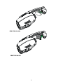
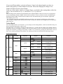
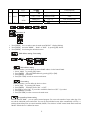
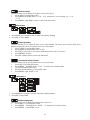
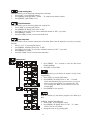
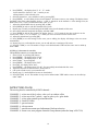
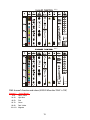
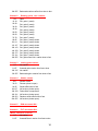
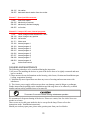
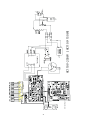
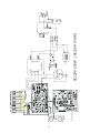
EVL PRO SCANNER 150-250 / PRO STAR 150-250
USER MANUAL
(VER3.3)
PLEASE KEEP THIS MANUAL FOR FUTURE REFERENCE
PRO SCAN 150-250
PRO STAR 150-250
1
For your own safety, please read this user manual carefully before installing the device.
Ke ep this devi ce away f rom rai n and moisture !
U nplug mains l ead before opening the housing.
Every person involved with the installation, operation and maintenance of this device has to:
-be qualified
-follow carefully the instructions of this manual
INTRODUCTION:
Thank you for having chosen this professional lighting
.
effect
You have acquired a powerful and versatile device.
Unpack the device. Inside the box you should find: the fixture device, a power cable, an
XLR connection cable, a safety cable and this manual. Please check carefully that there is no damage
caused by transportation. Should there be any, consult your dealer and don' t install this device.
Features:
Pan movement: pan 170 degrees
Tilt movement: tilt 85 degrees (Scanner)
3 operation mode: DMX controlled, stand alone or sound activated via built in microphone
9 colors plus white, with two direction rainbow effect,
Switchable colour change (mode 1: only full colours, mode 2: colour-change at every position)
7 rotating gobos plus open, with different speed gobo shaking effect
strobe effect : 0~10 flashes per second or random strobe
8 preset programs selectable
Control board with 4-digit display and foil-keyboard for adjusting the DMX-starting address,
Pan/tilt-Reverse, Program, Reset, lamp on/off, operating hours and etc
digital display can be turn 180 deg reverse to fit for different installation position
local or remote resetting
auto test for all functions
value of each DMX-channel can be displayed
save program : edit and save the program to the incorporated EEPROM through the front control
panel or external controller; can save maximum 48 scenes, and run the saved program by the 'run'
menu from the front control panel
SAFETY INSTRUCTIONS
Take care when operating this unit.
Internal High voltages are dangerous and can cause serious electrical shock.
2
For safe operation, it is absolutely necessary to follow the safety instructions and warning
notes written in this user manual.
If the device has been exposed to temperature changes due to environmental changes, do not switch
it on immediately. The arising condensation could damage the device. Leave the device switched off
until it has reached room temperature.
This device falls under protection-class I. Therefore it is essential that the device be earthed.
The electric connection must carry out by qualified person.
Make sure that the available voltage is not higher than stated at the end of this manual.
Make sure the power cord is never crimped or damaged by sharp edges. If this would be the case,
replacement of the cable must be done by an authorized dealer.
Always disconnect from the mains, when the device is not in use or before cleaning it. Only handle
the power cord by the plug. Never pull out the plug by tugging the power cord.
During initial start-up some smoke or smell may arise. This is a normal process and does not
necessarily mean that the device is defective, it should decrease gradually.
Never touch the device during operation!
T he housing may heat up
Never look directly into the light source.
Risk of possible epileptic fit.
Please be aware that damages caused by manual modifications to the device are not subject to
warranty. Keep away from children and non-professionals.
GENERAL GUIDELINES
This device is a lighting effect for professional use on stages, in discotheques, theatres, etc.
This fixture is only allowed to be operated with the max alternating current which stated in the
technical specifications in the last page of this manual, the device was designed for indoor use only.
Lighting effects are not designed for permanent operation. Consistent operation breaks may ensure
that the device will serve you for a long time without defects. Do not shake the device.
Avoid brute force when installing or operating the device.
While choosing the installation-spot, please make sure that the device is not exposed to extreme heat,
moisture or dust. The minimum distance between light-output from the
projector and the illuminated surface must be more than 0,5 meter.
Always fix the fixture with an appropriate safety cable if you use the clamp to hang up the fixture.
3
Operate the device only after having familiarized with its functions. Do not permit operation by
persons not qualified for operating the device. Most damages are the result of unprofessional
operation.
Please use the original packaging if the device is to be transported.
For safety reasons, please be aware that all modifications on the device are forbidden.
If this device will be operated in any way different to the one described in this manual, the product
may suffer damages and the guarantee becomes void. Furthermore, any other operation may lead to
short-circuit, burns, electric shock, lamp explosion, crash, etc.
INSTALLATION INSTRUCTIONS
a) Installing or replacing the lamp
Only install the lamp with the device unplugged from the mains.
T he lamp has to be replaced when it is damaged or deformed.
Before replacing the lamp let the lamp cool down, du ring operation, the lamp will
reach very high temperature.
Do not install lamps with a higher wattage. They generate higher temperatures than which the device
was designed for.
For the installation, you need one
CDMT150 lamp ;
or
MSD250/2 la mp ;
Procedure :
1
2
3
4
4
1) Unscrew the 2 screws on the back of the housing, holding the plate where the lamp is underneath.
2) Gently pull the socket holder using the knob in the middle.
3) Carefully insert the lamp into the socket. Please remember there is only one way to insert the lamp.
Gently slide the lamp and its lamp holder back into place and fasten the 2 screws.
4) On the access plate there are 3 small screws marked 1,2 and 3.which are used to adjust the lamp
holder in the lamp housing. You can adjust the 3 screws to fine-turn the position of the lamp to get
the maximum light output as shown below.
Please remember the lamp is not a hot-restrike type, you must wait for approximately 10
minutes after having turned off the lamp before you can turn it back on again.
Do NOT operate this device with the cover removed
b) Mounting the device
Please consider the EN 60598-2-17 and the other respective national norms during installation.
The installation of this product must only be carried out by qualified persons.
The installation of the effect has to be built and constructed in a way that it can hold 10 times the
weight for 1 hour without any harming deformation.
The installation must always be secured with a secondary safety attachment, e.g. an appropriate
safety cable.
Never stand directly below the device when mounting, removing or servicing the fixture.
The operator has to make sure the safety relating and machine technical installations are approved by
an expert before taking the device into operation for the first time.
These installations have to be approved by a skilled person once a year.
B efore taking into operation for the first time,
the installation has to be approved by an expert.
5
Cautions:
The effect should be installed outside areas where persons may reach it, walk by or be seated.
When installi ng the device, make sure there is no highly
inflammable material within a distance of min. 0,5m
Overhead mounting requires extensive experience, including amongst others calculating
working load limits, installation material being used, and periodic safety inspection of all
installation material and the device. If you lack these qualifications, do not attempt the
installation yourself. Improper installation can result in bodily injury.
T he electric connection must only be carried out by a qualified electrician.
Before mounting make sure that the installation area can hold a minimum point load of 10 times the
device's weight.
Connect the fixture to the mains with the power plug.
Installation method via clamp
Please refer to the picture below:
Screw one clamp each via a M10 screw and nut directly into the br acket of the scanner. Pull the safety-chain
through the bracket of the base and over the trussing system or a safe fixation spot.
DMX-512 control connection
Connect the provided XLR cable to the female 3-pin XLR output of your controller and the other
side to the male 3-pin XLR input of the Scanner/Star. You can chain multiple heads together through
serial linking. The cable needed should be two core, screened cable with XLR input and output connectors.
Please refer to the diagram overleaf (page 7)
6
DMX-512 connection with DMX terminator
For installations where the DMX cable has to run a long distance or is in an electrically noisy
environment, such as in a discotheque, it is recommended to use a DMX terminator. This helps in
preventing corruption of the digital control signal by electrical noise. The DMX terminator is simply
an XLR plug with a 120 Ω resistor connected between pins 2 and 3,which is then plugged into the
output XLR socket of the last fixture in the chain. Please see illustrations below.
projector 1
starting address 1
p rojector 2
starting address 9
projector 3
s tarting address 17
Projector DMX starting address selection
All fixtures should be given a DMX starting address when using a DMX signal, so that the correct
fixture responds to the correct control signals. This digital starting address is the channel number
from which the fixture starts to 'listen' to the digital control information sent out from the DMX
controller. The allocation of this starting address is achieved by setting the correct number on the
display located on the base of the device.
You can set the same starting address for all fixtures or a group of fixtures , or make different
address for each fixture individually.
If you set the same address, all the units will start to 'listen' to the same control signal from the same
channel number. In other words, changing the settings of one channel will affect all the fixtures
simultaneously.
7
If you set a different address, each unit will start to ' listen' to the channel number you have set,
based on the quantity of control channels of the unit. That means changing the settings of one
channel will affect only the selected fixture.
In the case of the scanner, which is a 8 channel fixture, you should set the starting address of the first
unit to 1, the second unit to 9 (8 + 1), the third to 17 (9 + 8), and so on.
Note:
After switching on, the machine will automatically detect whether DMX 512 data is received or not. If the data is
received, the display will show "A.001" with the actual set address. If there is no data received at the DMX-input,
the display flashes "A 001" with the actual set address & the unit automatically goes into Sound to Light mode.
This situation can occur if:
- the 3 PIN XLR plug (cable with DMX signal from controller) is not connected with the input of the machine.
- the controller is switched off or defective, if the cable or connector is defective or the signal wires are swap in the
input connector.
Control Board
The Control Board offers several features: you can simply set the starting address, switch on and off the lamp, run
the pre-programmed program or make a reset.
The main menu is accessed by pressing the Enter-button for 3 seconds until the display starts flashing. Browse
through the menu by pressing the Up-button. Press the Enter-button in order to select the desired menu. You can
change the selection by pressing the Up-button. Confirm every selection by pressing the Enter-button. You can
leave every mode by pressing the Exit-button. The functions provided are described in the following sections.
Default settings shaded.
Main
Sub menu
menu
ADDR
Extension
Display
Function
VALU
SLAV
A001~A511 (AXXX)
ON/OFF
(SLAV)
DMX address setting
Slave setting
Automatic Program Run
in Stand Alone
Automatic Program Run
as Master
Sound-controlled Program
Run in Stand Alone
Sound-controlled Program
Run as Master
Display the DMX 512 value
of each channel
Reverse display
Shut off LED display
ALON
(AU-A)
MAST
(AU-M)
ALON
(SO-A)
MAST
(SO-M)
AUTO
0
M ODE
RUN
SOUN
VALU
1
SE T
2
A DJ U
3
TIME
D-00 ~ D-30
(DXXX)
ON/OFF
ON/OFF
DISP
RDIS
CLDI
RPAN
ON/OFF
Pan Reverse
RTI L
REST
LODA
OLVE
VER
LADJ
TEST
MATI
ON/OFF
ON/OFF
ON/OFF
ON/OFF
V-1.0~V-9.9
ON/OFF
T-0 1 ~ T- 30
0000~9999 (hours)
Tilt Reverse
Reset
Restore factory settings
Software version change
Software version
Lamp adjustment
Test function of each channel
Fixture running time
LATI
0000~9999 (hours)
Lamp running time
CLMT
ON/OFF
Clear fixture time
8
4
CLLT
ON/OFF
STEP
S-01 ~ S- 48
SC 01
~
SC 48
E DI T
Clear lamp time
01XX (00~FFH)
30XX (00~FFH)
T - - X (1~ 9)
ON/OFF
C-01 ~ C-30
TIME (sec.)
CNIN
Steps of Program Run
Edit the channels of each
scene
Time for each scene
Edit program via controller
Main functions
- Main menu 0
1. Press [ENTER]
2. Press [ENTER]
3. Press [ENTER]
for 3 seconds to enter the main menu "M ODE " (display flashing)
and select "ADDR" , ' RUN' or "DISP" by pressing [UP] button.
for selecting the desired sub menu.
DMX address
addr ess setting,
setting, Slave
Slave setting
setting
/
DMX address setting.
With this function, you can adjust the desired DMX-address via the Control Board.
1. Select ' VALU' by pressing [UP] button.
2. Press [ENTER] , adjust the DMX address by pressing [U P] or [DN] .
3. Press [ENTER] to confirm.
4. Press [EX I T/DN] in order to return to main menu.
Slave setting.
With this function, you can define the device as slave.
1. Select 'SLAV ' by pressing [UP] button.
2. Press [ENTER] , the display shows 'ON ' or 'OFF' .
3. Press [UP] to select 'ON ' if you wish to enable this function or 'OFF ' if you don' t.
4. Press [ENTER] to confirm.
5. Press [EXI T/DN] in order to return to the main menu.
Program Run, Master setting
With the function "RUN" , you can run the internal program. You can set the number of steps under Step. You
can edit the individual scenes under Edit. You can run the individual scenes either automatically (AUTO), i.e.
with the adjusted Step-Time or sound-controlled (SOUN). The selection "ALON" means Stand Alone-mode and
"MAST" that the device is defined as master.
9
1.
2.
3.
4.
5.
Select "AUTO" or "SOUN" by pressing [UP] .
Press [ENTER] for selecting the desired extension menu.
Select "ALON" or "MAST" by pressing [UP] .
Press [ENTER] to confirm.
Press [EXI T/DN] in order to return to the main menu.
Display the DMX value, Reverse display, Shut off LED display
Display the DMX 512 value of each channel
With this function you can display the DMX 512 value of each channel.
1. Select "V ALU" by pressing [UP] .
2. Press [ENTER] to confirm; the display shows'D -00' . In this setting, the DMX-adjustment of every
channel will be displayed.
3. Press [UP] in order to select the desired channel. If you select 'D -14' the display will only show the
DMX-value of the 14th channel.
4. Press [ENTER] to confirm.
5. The display shows "D- XX' , 'X' stands for the DMX-value of the selected channel.
6. Press [ENTER] or [EXI T/DN] to exit.
Reverse display
With this function you can rotate the display by 180 deg
1. Select "rDIS" by pressing [UP] .
2. Press [ENTER], the display shows 'ON' ' or 'OFF'.
3. Press [UP] to select 'ON ' if you wish to enable this function or 'OFF ' if you don' t; the display will
rotate by 180 deg
.
4. Press [ENTER] or [EXI T/DN] to exit.
Shut off LED display
With this function you can shut off the LED display after 2 minutes.
1. Select "CLDI" by pressing [UP] .
2. Press [ENTER] , the display shows 'ON ' or 'OFF'.
3. Press [UP] to select 'ON ' if you wish to enable this function or 'OFF ' if you don' t.
4. Press [ENTER] or [EXI T/DN] to exit.
10
Main Menu 2
1. Press [ENTER] for 3 seconds to enter the main menu (display flashing).
2. Press [UP] to select 'SET .'
Pan Reverse
With this function you can reverse the Pan-movement.
1.
Select 'rPAN' by pressing [UP] button.
2.
Press [ENTER] , the display shows 'ON ' or 'OFF'.
3.
Press [UP] to select 'ON ' if you wish to enable this function or 'OFF ' if you don' t.
4.
Press [ENTER] or.
Tilt Reverse
With this function you can reverse the Tilt-movement.
1.
Select 'rTIL' by pressing [UP] button.
2.
Press [ENTER] , the display shows 'ON ' or 'OFF'.
3.
Press [UP] to select 'ON ' if you wish to enable this function or 'OF F ' if you don' t.
5.
Press [ENTER] or [EX I T/DN] to exit.
Reset
With this function you can Reset the device via the Control Board.
1.
Select 'rEST' by pressing [UP] button.
2.
Press [ENTER] , the display shows 'ON ' or 'OFF'
3.
Press [UP] to select 'ON ' if you wish to enable this function or 'OFF ' if you don' t.
4.
Press [ENTER] or [EXI T/DN] to exit.
Restore factory settings
With this function you can restore the factory settings of the device. All settings will be set back to the default
values (shaded). Any edited scenes will be lost.
1.
Select 'LODA ' by pressing [UP] button.
2.
Press [ENTER] , the display shows 'ON ' or 'OFF'.
3.
Press [UP] to select 'ON ' if you wish to enable this function or 'OFF ' if you don' t.
4.
Press [ENTER] to confirm.
5.
Press [EXI T/DN] in order to return to the main menu.
Software version change
With this function you can change the software version of the device
1.
Select 'OLV E' by pressing [UP] button.
2.
Press [ENTER] , the display shows 'ON ' or 'OFF' .
3.
Press [UP] to select 'ON ' is VER3.2 or 'OFF' is VER3.3
4.
Press [ENTER] to confirm.
5.
Press [EXI T/DN] in order to return to the main menu.
11
Software version
With this function you can display the software version of the device.
1.
Select 'VER ' by pressing [UP] button.
2.
Press [ENTER] , the display shows 'V -X .X ' , ' X.X' stands for the version number, e.g. ' V-1.0' ,
'V -2.6' .
3.
Press [ENTER] or [EXI T/DN] in order to return to the main menu.
Main menu 3
1. Press [ENTER] for 3 seconds to enter the main menu (display flashing).
2. Press [UP] to select ' ADJ U' .
Lamp adjustment
With this function you can adjust the lamp via the Control Board. The shutter opens and the lamp can be
adjusted. In this mode, the device will not react to any control signal.
1.
Select ' L ADJ' by pressing [UP] button.
2.
Press [ENTER] , the display shows 'ON ' or 'OFF'.
3.
Press [UP] to select 'ON ' if you wish to enable this function or 'OFF ' if you don' t.
4.
Press [ENTER] to confirm.
5.
Press [EX I T/DN] in order to return to the main menu.
Test function of each channel
With this function you can test each channel on its (correct) function.
1.
Select 'tESt' by pressing [U P] button.
2.
Press [ENTER] , the display shows 'T -X X' , ' X' stands for the channel number.
3.
The current channel will be tested.
4.
Select the desired channel by pressing [UP] button.
5.
Press [ENTER] or [EX I T/DN] to exit.
Main menu 4
1. Press [ENTER] for 3 seconds to enter the main menu (display flashing).
2. Press [UP] to select 'TIME'.
Fixture running time
With this function you can display the running time of the device.
1.
Select 'MA T I ' by pressing [UP] button.
2.
Press [ENTER] , the display shows ' X X XX' , ' X' stands for the number of hours.
3.
Press [ENTER] or [EX I T/DN] to exit.
12
Lamp running time
With this function you can display the running time of the lamp.
1.
Select 'LA T I ' by pressing [UP] button.
2.
Press [ENTER] , the display shows ' X X XX' , ' X' stands for the number of hours.
3.
Press [ENTER] or [EXI T/DN] to exit.
Clear fixture time
With this function you can clear the running time of the device.
1.
Select 'CLMT' by pressing [UP] button.
2.
Press [ENTER], the display shows 'ON ' or 'OFF' .
3.
Press [UP] to select 'ON ' if you wish to enable this function or 'OFF ' if you don' t.
4.
Press [ENTER] to confirm.
5.
Press [EXI T/DN] in order to return to the main menu.
Clear lamp time
With this function you can clear the running time of the lamp. Please clear the lamp time every time you replace
the lamp.
1.
Select 'C LL T ' by pressing [UP] button.
2.
Press [ENTER] , the display shows 'ON ' or 'OFF' .
3.
Press [UP] to select 'ON ' if you wish to enable this function or 'OF F ' if you don' t.
4.
Press [ENTER] to confirm.
5.
Press [EX I T/DN] in order to return to the main menu.
Main menu 5
1. Press [ENTER] for 3 seconds to enter the main menu
(display flashing).
2. Press [UP] to select 'EDIT' .
- Define the number of steps in Run
With this function you can define the number of steps in the
Program Run.
1. Select 'STEP' by pressing [UP] button.
2. Press [ENTER] , the display shows 'S -XX' ,' X' stands
for the total amount of steps you want to save, so you can
call up to 48 scenes in 'R UN' . For example if the ' XX'
is 05, it means that ' RUN' will run the first 5 scenes you
saved in 'EDIT' .
3. Press [ENTER] to save and exit.
- Editing the channels of the individual scenes
With this function you can edit the program to be called up in
Run.
a) Editing via the C ontr ol Boar d
1. Select 'SC 01' by pressing [UP] button.
2. Press [ENTER] , the display shows 'S C XX' , 'X' stands
for the scene no. to be edited.
3. Change the scene no. by pressing [UP] .
13
4. Press [ENTER] , the display shows 'C -X ' , 'X' stands
for the channel no. Such as 'C -01' , it means you are
editing channel 1 of the selected scene.
5. Select the channel no. you would like to edit by pressing [UP] .
6. Press [ENTER] to enter editing for the selected channel , the fixture reacts to your settings. The display shows
the DMX value of the edited channel. Such as ' 11XX', it stands for in the channel 11 of the editing scene, the
DMX value is XX , XX is a hexadecimal number value ' 01-FF'.
7. Adjust the desired DMX value by pressing [UP] or [DN] .
8. Press [ENTER] in order to edit other channels of this scene.
9. Repeat steps 5-9 until you finish setting all the DMX values for all channels of this scene.
10. Once all the channels completed, the display will flash 'tIME'
11. Press [ENTER] to edit the time needed, the display shows 't --X','X' stands for the time needed to run the
current scene, value ' 1-9'. F or example, ' t--2' means you need 2 seconds to run the current scene.
12. Adjust the desired time by pressing [UP] .
13. Press [ENTER] to save the settings for the scene you are editing, the display will change to the next scene
automatically.
14. Repeat step 3-14 to edit and other scenes, you can edit and save a maximum of 48 scenes.
15. Press [EX I T/DN] to exit. The number of steps can be defined under 'STEP' and the scenes can be called up
under ' RUN'
b) Editing vi a the external controller
Call up the first scene in your contr oller now.
1. Select 'SC 01' by pressing [UP] button.
2. Press [ENTER] , the display shows 'SC 01' .
3. Press [ENTER] , the display shows 'C -01' .
4. Select "CNIN " by pressing [UP] .
5. Press [ENTER] , the display shows "OFF" .
6. Press [UP] , the display shows "ON" .
7. Press [ENTER] , the display shows "SC 02" . You successfully downloaded the first scene.
8. Adjust the Step-time as described above under point 12.
9. Call up the second scene in your controller now.
10. Repeat steps 5-11 until all desired scenes are downloaded.
11. Press [EXI T/DN] to exit. The number of steps can be defined under 'STEP' and the scenes can be called up
under ' RUN'
INSTRUCTIONS ON USE:
The moving head is controlled by 8 DMX channels :
CHANNEL 1 : select one of the 9 colors, color cycle or rainbow effect
CHANNEL 2 : select one of the 7 goboís + open or gobo cycle+ gobo shake
CHANNEL 3 : select gobo rotation speed and direction
CHANNEL 4 : Strobe (0-10Hz)
CHANNEL 5 : pan movement
CHANNEL 6 : tilt movement
CHANNEL 7 : pan/tilt movement speed adjustment, blackout selection
CHANNEL 8 : motor reset ,auto program control & Lamp dimmer(when the lamp is ELC250)
14
V3.2
La m p
Dim m e r
V3.3
La m p
Dim m e r
DMX channel's function and values:(V ER3.2 When the 'OLV E' is 'ON')
Channel 1
0-19
20-39
40-59
60-79
80-99
100-119
- Color Wheel 1 :
Open / white
Light blue
Pink
Green
Dark Yellow
Magenta
15
120-139
140-159
160-179
180-199
200-255
Channel 2 -
Light Yellow
Yellow Green
Blue
Red
Backwards rainbow effect from slow to fast
Rotating gobos, cont. rotation :
0-13
14-27
28-41
42-55
56-69
70-83
84-97
98-115
116-135
136-155
156-175
176-195
196-215
216-235
236-255
Open
Rot. gobo 1 (metal)
Rot. gobo 2 (metal)
Rot. gobo 3 (metal)
Rot. gobo 4 (metal)
Rot. gobo 5 (metal)
Rot. gobo 6 (metal)
Rot. gobo 7 (metal)
Rot. gobo 1 (metal) shake
Rot. gobo 2 (metal) shake
Rot. gobo 3 (metal) shake
Rot. gobo 4 (metal) shake
Rot. gobo 5 (metal) shake
Rot. gobo 6 (metal) shake
Rot. gobo 7 (metal) shake
Channel 3 -
rotating gobo rotation :
0-7
8-127
128-135
136-255
Channel 4 0-31
32-63
64-95
96-127
128-159
160-191
192-223
224-255
No rotation
forwards gobo rotation from fast to slow
No rotation
Backwards gobo rotation from slow to fast
Shutter, strobe:
Shutter closed
Dimmer (close to open)
Strobe effect slow to fast
No function (shutter open)
Pulse-effect in sequences
No function (shutter open)
Random strobe effect slow to fast
No function (shutter open)
Channel 5
- PAN movement 8bit :
Channel 6
- TILT movement 8bit :
16
(When Channel 6 is Barrel )
0-7
8-127
128-135
136-255
No rotation
forwards Barrel rotation from fast to slow
No rotation
backwards barrel rotation from slow to fast
Channel 7 - Speed pan/tilt movement:
0-225
max to min speed
226-235 blackout by movement
236-245 blackout by all wheel changing
246-255 no function
Channel 8 - reset, internal programs:
0-19
20-39
40-59
60-79
80-99
100-119
120-139
140-159
160-179
180-199
200-219
220-239
240-255
255
colour change normal
colour change to any position
colour change normal &Dimmer 0%~100%
No function
Motor reset
Internal program 1
Internal program 2
Internal program 3
Internal program 4
Internal program 5
Internal program 6
Internal program 7
Internal program 8
Active music control
DMX channel's function and values:(VER 3.3 When the 'OLVE' is 'OFF')
Channel 1
0-12
13-25
26-38
39-51
52-64
65-77
78-90
91-103
104-116
117-127
128-187
188-193
- Color Wheel 1 :
Open / white
Red
Blue
Yellow Green
Light Yellow
Magenta
Dark Yellow
Green
Pink
Light blue
Forwards rainbow effect from fast to slow
No rotation
17
194-255
Channel 2 0-9
10-19
20-29
30-39
40-49
50-59
60-69
70-79
80-95
96-111
112-127
128-143
144-159
160-175
176-191
192-255
Channel 3 0-7
8-127
128-135
136-255
Channel 4 0-31
32-63
64-95
96-127
128-159
160-191
192-223
224-255
Backwards rainbow effect from slow to fast
Rotating gobos, cont. rotation :
Open
Rot. gobo 1 (metal)
Rot. gobo 2 (metal)
Rot. gobo 3 (metal)
Rot. gobo 4 (metal)
Rot. gobo 5 (metal)
Rot. gobo 6 (metal)
Rot. gobo 7 (metal)
Rot. gobo 1 (metal) shake
Rot. gobo 2 (metal) shake
Rot. gobo 3 (metal) shake
Rot. gobo 4 (metal) shake
Rot. gobo 5 (metal) shake
Rot. gobo 6 (metal) shake
Rot. gobo 7 (metal) shake
Rot. gobo wheel cont. rotation slow to fast
rotating gobo rotation :
No rotation
forwards gobo rotation from fast to slow
No rotation
Backwards gobo rotation from slow to fast
Shutter, strobe:
Shutter closed
Dimmer (close to open)
Strobe effect slow to fast
No function (shutter open)
Pulse-effect in sequences
No function (shutter open)
Random strobe effect slow to fast
No function (shutter open)
Channel 5
- PAN movement 8bit :
Channel 6
- TILT movement 8bit :
(When Channel 6 is Barrel )
0-7
8-127
No rotation
forwards Barrel rotation from fast to slow
18
128-135
136-255
No rotation
backwards barrel rotation from slow to fast
Channel 7 - Speed pan/tilt movement:
0-225
max to min speed
226-235 blackout by movement
236-245 blackout by all wheel changing
246-255 no function
Channel 8 - Lamp on/off, reset, internal programs:
0-127
128-138
139-160
161-171
172-182
183-193
194-204
205-215
216-226
227-237
238-248
249-254
255
colour change normal &Dimmer 0%~100%
colour change to any position
No function
Motor reset
Internal program 1
Internal program 2
Internal program 3
Internal program 4
Internal program 5
Internal program 6
Internal program 7
Internal program 8
Active music control
CLEANING AND MAINTENANCE
The following points have to be considered during the inspection:
1) All screws for installing the devices or parts of the device have to be tightly connected and must
not be corroded.
2) There must not be any deformations on the housing, color lenses, fixations and installation spots
(ceiling, suspension, trussing).
1) Mechanically moved parts must not show any traces of wearing and must not rotate with
unbalances.
2) The electric power supply cables must not show any damage, material fatigue or sediments.
Further instructions depending on the installation spot and usage have to be adhered by a skilled
installer and any safety problems have to be removed.
Disconnect from mains before starting maintenance operation.
We recommend a frequent cleaning of the device. Please use a moist, lint- free cloth. Never use
alcohol or solvents.
There are no serviceable parts inside the device except for the lamp. Please refer to the
instructions under ' Installation instructions'.
Should you need any spare parts, please order genuine parts from your local dealer.
19
TECHNICAL SPEC IFICAT IONS
Power supply :
110VAC,50Hz;
110VAC,60Hz;
120VAC, 50Hz; 20VAC,50Hz; 230VAC,50Hz; 240VAC, 50Hz;
120VAC,60Hz; 220VAC,60Hz; 230VAC,60Hz; 240VAC,60Hz;
Power consumption: max. 250W 300W 400W
Lamp :
CDMT150 GY9.5 socket, Metal Halide;
MSD250 GY9.5 socket, Metal Halide;
Motors : 6 micro motors
Net weight :
10.5KGS;
Gross weight: 12.5KGS;
Packing dimensions : 64x37x37cm
12KGS;
14KGS;
Erors and omissions for every information given in this manual excepted. All information is subject to change
without prior notice.
20
MI NI - CONTROL- 04
DMX512
30P
10K
DMX512
LED7X4
104
30P
10PI N
87LPC768
2K
2K
2K
2K
470
10K
COLOR CM
8 7LPC768
16MHz
2200UF/ 25V
104
4A
104
4A
4A
TWO AC12V
470U/ 16V
SCAN6CH- 01
4A
104
30P
SCAN6CH- 01
100
4. 7K
220 0UF/ 50V
FAN
CM1
L293D
AT89C52/ 1
CAT24C021
16MHz
1015
30P
10K
L293D
1015
1015
87LPC768
10K
4. 7K
30P
10K
2200 UF/ 25V
9013
30P
150K
16MHz
10K
104
104
30P
2200UF/ 25V
150K
2200UF/ 25V
10K
2200UF/ 25V
1K
16MHz
2200UF/ 25V
SW- PB
FAN
CON20
5. 6K
1015
4069
CM- 03
LI NK PANTI L- PCB J ACK
104
104
RS807
7805
SCAN6CH- A02
MI NI - CONTROL- 04
L293D
104
1UF/ 50V
3V
J P1
30P
CM- 03
SW- PB
I N4148x2
SN75176
LI NK PANTI L- PCB J ACK
J1
VR100K
SW-PB
I N4148
I N41 4 8
104
104
MI C
470U/ 16V
21
AC110V- 250W ( AC110V- 150W)
FAN
DC24V
TRANSFORMER
AC10V
0
AC10V
( CDMT150)
MI NI - CONTROL- 04
DMX512
30P
10K
DMX512
LED7X4
104
30P
10PI N
87LPC768
2K
2K
2K
2K
470
10K
COLOR CM
8 7LPC768
16MHz
2200UF/ 25V
104
4A
104
4A
4A
TWO AC12V
470U/ 16V
SCAN6CH- 01
4A
104
30P
SCAN6CH- 01
100
4. 7K
220 0UF/ 50V
FAN
CM1
L293D
AT89C52/ 1
CAT24C021
16MHz
1015
30P
10K
L293D
1015
1015
87LPC768
10K
4. 7K
30P
10K
2200 UF/ 25V
9013
30P
150K
16MHz
10K
104
104
30P
2200UF/ 25V
150K
2200UF/ 25V
10K
2200UF/ 25V
1K
16MHz
2200UF/ 25V
SW- PB
FAN
CON20
5. 6K
1015
4069
CM- 03
LI NK PANTI L- PCB J ACK
104
104
RS807
7805
SCAN6CH- A02
MI NI - CONTROL- 04
L293D
104
1UF/ 50V
3V
J P1
30P
CM- 03
SW- PB
I N4148x2
SN75176
LI NK PANTI L- PCB J ACK
J1
VR100K
SW-PB
I N4148
I N41 4 8
104
104
MI C
470U/ 16V
22
AC220V- 250W ( AC220V- 150W)
FAN
DC24V
TRANSFORMER
AC10V
0
AC10V
( CDMT150)
NOTES
23