1
3 DIS./ASSEMBLY
1
SCANNER SECTION
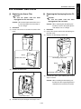
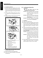
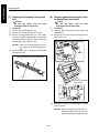
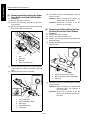
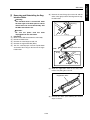
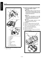
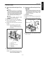
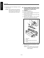
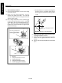
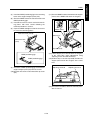
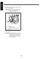
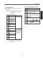
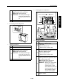
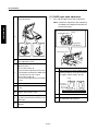
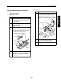
b. Installation procedure
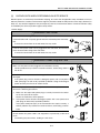
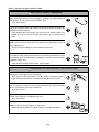
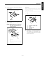
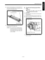
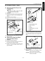
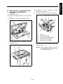
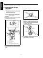
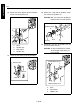
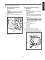
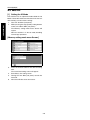
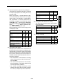
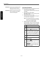
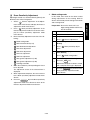
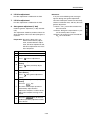
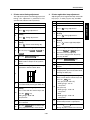
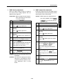
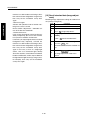
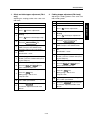
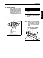
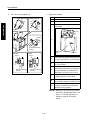
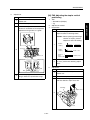
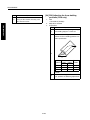
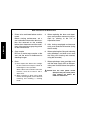
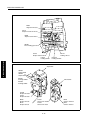
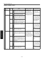
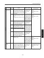
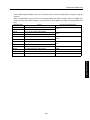
(1) Move the V-mirror unit toward the paper exit side,
then insert the optics positioning jigs from the
front to secure the V-mirror unit. Ensure that the
optics positioning jigs pass through the V-mirror
unit.
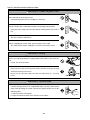
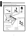
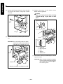
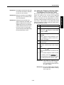
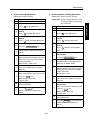
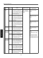
(2) Insert the optics positioning jigs in the holes at
the exposure unit mounting position from the
front.
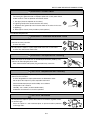
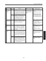
(3) Slide the exposure unit to the paper exit side until
it touches the optics unit positioning jig.
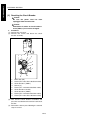
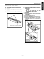
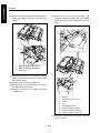
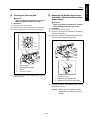
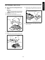
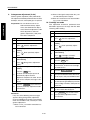
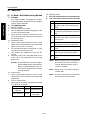
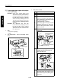
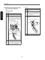
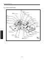
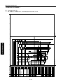
[5] Installing the Optics Wire
1
a.
(1)
(2)
2
4
3
(3)
5
6
7
3
8
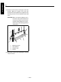
1.
2.
3.
4.
5.
6.
7.
8.
(4)
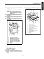
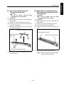
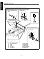
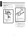
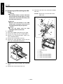
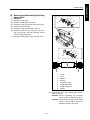
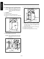
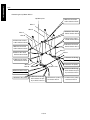
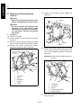
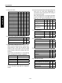
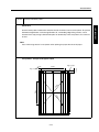
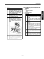
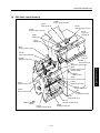
Exposure unit fixing hole
Unused hole
Optics unit positioning jig
V-mirror unit
Stopping surface
Exposure unit
For exposure unit positioning
V-mirror unit fixing hole (left)
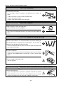
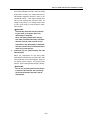
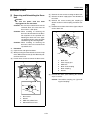
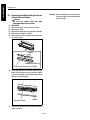
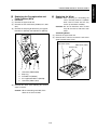
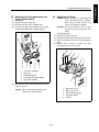
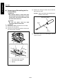
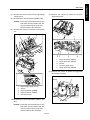
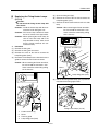
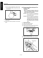
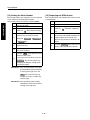
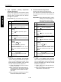
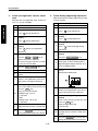
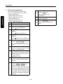
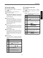
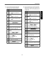
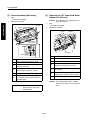
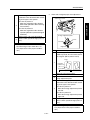
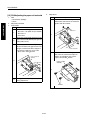
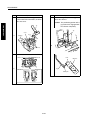
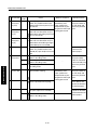
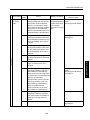
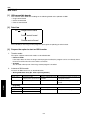
(4) Install the exposure unit to the optics wire mounting bracket with four screws.
(5) Remove two optics unit positioning jigs.
(6) Reverse the removal procedure to reinstall the
removed parts.
1-C-4
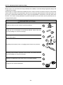
Caution:
Be sure the power cord has been
unplugged from the wall outlet.
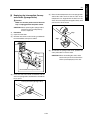
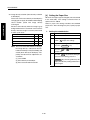
Caution1: When winding the optics wire around
the pulley, be sure to run the wire
tightly so that it does not ride on the
side of the pulley.
Caution2: When re-tensioning or replacing the
optics wire, be sure to use the optics
positioning jig.
Caution3: Be sure to perform image adjustment after replacing or re-installing
the wire (See "ADJUSTMENT.")
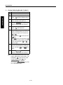
Procedure
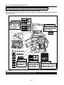
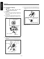
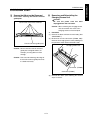
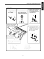
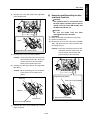
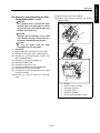
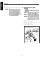
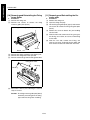
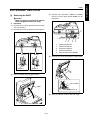
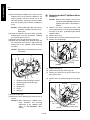
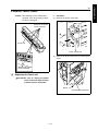
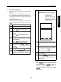
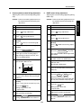
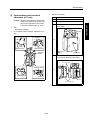
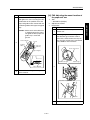
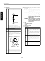
Remove the exposure unit.
Move the V-mirror unit toward the paper exit side
then insert the optics positioning jigs from the
front to secure the V-mirror unit. Ensure that the
optics positioning jigs pass through the V-mirror
unit.
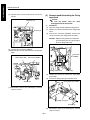
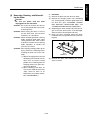
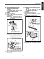
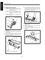
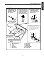
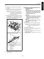
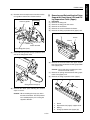
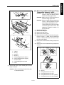
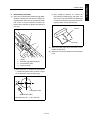
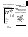
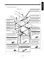
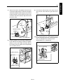
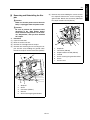
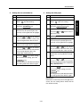
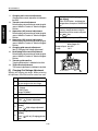
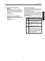
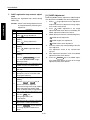
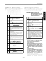
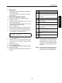
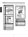
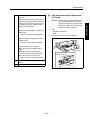
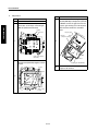
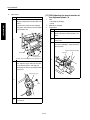
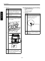
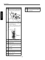
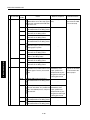
Place the metal bead at the midpoint of each
optics wire in the mounting hole in the drive pulley. Starting at this point, wind the optics wire five
turns to the outside and four times to the inside
on the drive pulley.
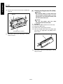
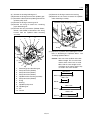
Caution1: Ensure that there is a metal bead at
the end of the outer wire, and a wire
terminal at the end of the inner wire.
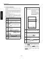
Caution2: Pull out the outer wire from above the
drive pulley in the paper exit direction, and the inner wire from under
the drive pulley in the paper feed
direction.
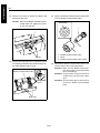
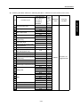
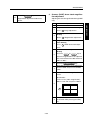
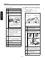
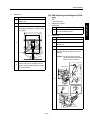
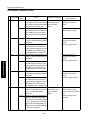
After winding the outer wire, secure it to the wire
stopper via the outside of pulley 1 and V-mirror
pulley through the notch in the wire stopper.