1
Service Manual
Field Service
Di650
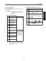
Dual references may be used on the following:
EDH
: RADF
FN-6, FN-112
C-403, C-404
: FNS
: LT & LCT
Cover Inserter B
PK-2
: PI
: PK
In-System Writer
: ISW
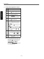
DESCRIPTION ITEM S FOR DANGER, W ARNING
AND CAUTION
SAFETY WARNINGS
SAFETY CIRCUITS
S-1
. . . . . . . . . . . . . . . . . . .S-2
. . . . . . . . . . . . . . . . . . .S-10
INDICATION OF WARNING ON THE M ACH INE
. . .S-12
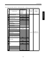
EXTERNAL SECTION........................................... 1-A-1
[1]
Replacing the Ozone Filter .....................1-A-1
[2]
Replacing the Developing Suction
Filter ....................................................... 1-A-1
[3]
Removing and Reinstalling the External
Covers .................................................... 1-A-2
[4]
Changing the Operation Panel Attachment
Angle and Removing/Reinstalling .......... 1-A-4
[5]
Resetting the Circuit Breaker ................. 1-A-6
DRIVE SECTION................................................... 1-B-1
[1]
Removing and Reinstalling the Drum
Motor(M2) ............................................... 1-B-1
[2]
Removing and Reinstalling the Fixing
Input Gear .............................................. 1-B-2
SCANNER SECTION ............................................1-C-1
[1]
Screws that Must not be Removed ........1-C-1
[2]
Removing and Reinstalling the
CCD Unit ................................................1-C-1
[3]
Replacing the Exposure Lamp ...............1-C-2
[4]
Removing and Reinstalling
the Exposure Unit ...................................1-C-3
[5]
Installing the Optics Wire........................1-C-4
[6]
Cleaning the Slit Glass
and Platen Glass ....................................1-C-6
WRITE SECTION ..................................................1-D-1
[1]
Removing and Reinstalling
the Write Unit..........................................1-D-1
[2]
Cleaning the Dust-proof Glass ...............1-D-2
DRUM UNIT........................................................... 1-E-1
[1]
Removing and Reinstalling
the Drum Unit ......................................... 1-E-1
[2]
Installing the Coupling ............................ 1-E-2
[3]
Removing, Cleaning, and Reinstalling
the Drum.................................................1-E-3
[4]
Removing and Reinstalling the Separation
Claws and Separation Claw Solenoid .... 1-E-4
[5]
Removing and Reinstalling the Toner
Control Sensor Board ............................. 1-E-6
CORONA UNIT...................................................... 1-F-1
[1]
Screws that Must not be Removed ........ 1-F-1
[2]
Removing and Reinstalling the Charging
Corona Unit ............................................ 1-F-1
[3]
Removing and Reinstalling the Charge
Control Plate........................................... 1-F-2
[4]
Replacing the Charging Wires................ 1-F-2
[5]
Removing and Reinstalling the Charging
Wire Cleaning Unit ................................ 1-F-3
[6]
Removing and Reinstalling the PCL....... 1-F-3
[7]
Cleaning the Charging Corona
Unit/PCL ................................................. 1-F-4
[8]
Removing and Reinstalling the Transfer/
Separation Corona Unit .......................... 1-F-4
[9]
Removing and Reinstalling the Plunger
Prevention Plate ..................................... 1-F-5
3 DIS./ASSEMBLY
1
. . . . . . . . . . . . . . . . . .S-1
3 2DIS./ASSEMBLY
ADJUSTMEN
IMPORTANT NOTICE
1. DISASSEMBLY/ASSEMBLY
3 DIS./ASSEMBLY
3 SERVICE
SAFETY AN D IM PORTAN T W ARN ING ITEM S S-1
4 ELECTRIC
3 DIS./ASSEMBLY
PARTS LIST
CONTENTS
3 DIS./ASSEMBLY
5 ISW
CONTENTS
3 DIS./ASSEMBLY
1
3 2DIS./ASSEMBLY
ADJUSTMEN
3 DIS./ASSEMBLY
3 SERVICE
4 ELECTRIC
3 DIS./ASSEMBLY
PARTS LIST
3 DIS./ASSEMBLY
5 ISW
CONTENTS
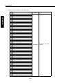
[10]
Replacing the Transfer/Separation
Wires and Transfer/Separation Wire
Cleaning Block........................................ 1-F-5
[11] Removing and Reinstalling the TSL
Unit ......................................................... 1-F-7
DEVELOPING UNIT ............................................. 1-G-1
[1]
Screws that must not be Removed........ 1-G-1
[2]
Removing and Reinstalling the
Developing Unit ..................................... 1-G-1
[3]
Replacing the Developer ....................... 1-G-2
[4]
Cleaning the Developing Unit
Bias shaft............................................... 1-G-3
TONER SUPPLY UNIT..........................................1-H-1
[1]
Replacing and Cleaning
the Toner Cartridge ................................1-H-1
CLEANING/TONER RECYCLE UNIT .................... 1-I-1
[1]
Removing and Reinstalling
the Cleaning Blade .................................. 1-I-1
[2]
Removing and Reinstalling the Toner
Guide Roller (TGR).................................. 1-I-2
PAPER FEED UNITS OF TRAYS 1 AND 2........... 1-J-1
[1]
Removing and Reinstalling the Paper
Feed Unit ................................................ 1-J-1
[2]
Removing and Reinstalling the Paper
Feed Trays 1 and 2 ................................ 1-J-1
[3]
Removing and Reinstalling the Paper
Feed Roller and Feed Roller Rubber...... 1-J-2
[4]
Removing and Reinstalling the Double
Feed Prevention Roller Rubber .............. 1-J-2
[5]
Replacing the Pre-registration and
Feed Clutches (MCs).............................. 1-J-3
[6]
Replacing the Wires ............................... 1-J-3
PAPER FEED UNIT OF TRAY 3 ........................... 1-K-1
[1]
Removing and Reinstalling the Paper
Feed Unit ................................................ 1-K-1
[2]
Removing and Reinstalling
Paper Feed Tray 3.................................. 1-K-1
[3]
Removing and Reinstalling the Paper
Feed Roller and Feed Roller Rubber..... 1-K-2
[4]
Removing and Reinstalling the Double
Feed Prevention Roller Rubber .............. 1-K-2
[5]
Replacing the Pre-registration and
Feed Clutches (MCs).............................. 1-K-3
[6]
Replacing the Wires ...............................1-K-3
BY-PASS FEED TRAY .......................................... 1-L-1
[1]
Removing and Reinstalling the by-pass
Feed Tray .............................................. 1-L-1
[2]
Replacing the Paper Feed Roller/Paper
Feed Roller Rubber ................................ 1-L-1
[3]
Replacing the Double Feed Prevention
Roller Rubber ......................................... 1-L-2
VERTICAL CONVEYANCE SECTION ................. 1-M-1
[1]
Removing and Reinstalling the Vertical
Conveyance Section.............................. 1-M-1
[2]
Removing and Reinstalling the Vertical
Conveyance MC (MC11, MC12) ........... 1-M-1
ADU UNIT.............................................................. 1-N-1
[1]
Drawing out and Reinstalling
the ADU Stand ....................................... 1-N-1
[2]
Cleaning the Paper Dust
Removing Brush.....................................1-N-1
[3]
Cleaning the Paper Mis-centering PS
(PS70)/Leading Edge PS (PS43) ........... 1-N-2
[4]
Removing and Reinstalling the
Registration MC (MC1) .......................... 1-N-2
[5]
Removing and Reinstalling the Second
Paper Feed Unit .................................... 1-N-3
[6]
Cleaning the Registration PS (PS44) .....1-N-4
[7]
Removing and Reinstalling the
Registration Roller.................................. 1-N-5
[8]
Removing and Reinstalling the
Pre-transfer Roller .................................. 1-N-6
[9]
Cleaning the ADU Paper Reverse
PS (PS45)/Reverse/Exit PS (PS46) ....... 1-N-7
[10] Removing and Reinstalling the ADU
Reverse Roller ....................................... 1-N-9
[11] Removing and Reinstalling
the ADU Stand ..................................... 1-N-10
[12] Removing and Reinstalling the Preregistration Roller ................................. 1-N-11
[13] Removing and Reinstalling the ADU
Conveyance Roller 3 and 4 .................. 1-N-12
[14] Removing and Reinstalling the ADU
Conveyanece Roller 1 and 2 ................ 1-N-15
[15] Removing and Reinstalling the Paper
Reverse/Exit Roller .............................. 1-N-17
FIXING UNIT .........................................................1-O-1
[1]
Removing and Reinstalling
the Fixing Unit ........................................1-O-1
[2]
Removing and Reinstalling
the Fixing Unit (Top)...............................1-O-1
[3]
Removing and Reinstalling
the Web Cover .......................................1-O-2
[4]
Removing and Reinstalling
the Cleaning Web...................................1-O-2
[5]
Replacing the Fixing Heater
Lamps (L2, L3) .......................................1-O-3
[6]
Replacing the Fixing Heater
Lamp(L4) ................................................1-O-4
[7]
Removing and Reinstalling the Fixing
Separation Claw (Upper) Unit and Fixing
Separation Claws (Upper) ......................1-O-5
[8]
Removing and Reinstalling the Fixing
Separation Claw (Lower) Unit and Fixing
Separation Claws (Lower) ......................1-O-6
[9]
Removing and Reinstalling the Fixing
Upper Roller ...........................................1-O-7
[10] Removing and Reinstalling the Fixing
Lower Roller ...........................................1-O-8
[11] Removing and Reinstalling
the De-curler ..........................................1-O-8
< RADF >
EXTERNAL SECTION ...........................................1-P-1
[1]
Removing the RADF...............................1-P-1
[2]
Reinstalling the RADF ............................1-P-2
ORIGINAL FEED/CONVEYANCE/EXIT
SECTION ...............................................................1-P-4
[1]
Replacing the Pickup Roller and
Conveyance Roller Rubber.....................1-P-4
[2]
Cleaning the Cleaning Pad .....................1-P-5
[3]
Replacing the Double Feed Prevention
Roller / Double Feed Prevention Roller
Rubber ....................................................1-P-5
< LCT >
PAPER FEED SECTION ...................................... 1-Q-1
[1]
Cleaning the Paper Dust Removing
Brush ..................................................... 1-Q-1
[2]
Cleaning the LT feed PS (PS106)/
LT first paper feed PS(PS107)............... 1-Q-1
[3]
Removing and Reinstalling the
Paper Feed Roller Unit .......................... 1-Q-2
[4]
Replacing the Paper Feed Roller Rubber/
Feed Roller Rubber ............................... 1-Q-2
[5]
Replacing the Double Feed
Prevention Roller Rubber ...................... 1-Q-3
[6]
Replacing the LT feed MC (MC101)/
LT first paper feed MC (MC102) ............ 1-Q-5
[7]
Replacing the C-403 Up/Down Wires .... 1-Q-6
[8]
Replacing the C-404 Up/Down Wires .. 1-Q-10
< FN >
EXTERNAL SECTION .......................................... 1-R-1
[1]
Removing and Reinstalling the Booklet
Tray (FN-6 only)..................................... 1-R-1
[2]
Removing and Reinstalling the Top
Cover/1 .................................................. 1-R-1
[3]
Removing and Reinstalling the Top
Cover/2 .................................................. 1-R-2
[4]
Removing and Reinstalling the Side
Cover ..................................................... 1-R-2
[5]
Removing and Reinstalling the Front
Door ....................................................... 1-R-3
[6]
Removing and Reinstalling the Rear
Cover ..................................................... 1-R-3
[7]
Removing and Reinstalling the Main
Tray ....................................................... 1-R-4
[8]
Removing and Reinstalling the Main
Paper Exit Opening Cover ..................... 1-R-5
< PI >
EXTERNAL SECTION........................................... 1-S-1
[1]
Detaching / Re-installing
the External covers................................. 1-S-1
PAPER FEED UNIT............................................... 1-S-2
[1]
Replacing the Paper feed roller and
Feed roller .............................................. 1-S-2
[2]
Replacing the Double feed prevention
roller and Torque limiter ......................... 1-S-3
< PK >
PUNCH SECTION ................................................. 1-T-1
[1]
Replacing the Punch unit ....................... 1-T-1
[2]
Cleaning the Punch Edges and Punch
Scraps Full PS (PS802) ......................... 1-T-2
3 DIS./ASSEMBLY
1
Removing and Reinstalling the Booklet
Paper Exit Opening Cover......................1-R-5
CONVEYANCE SECTION.....................................1-R-6
[1]
Replacing the Paper Exit Roller
(Sponge Roller) ......................................1-R-6
[2]
Replacing the Intermediate Conveyance
Roller (Sponge Roller) ...........................1-R-7
[3]
Removing and Reinstalling the Paper
Exit Opening Unit ...................................1-R-8
MAIN TRAY SECTION ..........................................1-R-9
[1]
Replacing the Tray Up/down Motor
(M703) ....................................................1-R-9
[2]
Replacing the Up/Down Wire .................1-R-9
STACKER SECTION...........................................1-R-13
[1]
Removing and Reinstalling the Stacker
Unit Cover ............................................1-R-13
[2]
Removing and Reinstalling the Stacker
Unit .......................................................1-R-13
STAPLER SECTION ...........................................1-R-15
[1]
Removing and Reinstalling the Stapler
Unit Cover ...........................................1-R-15
[2]
Removing and Reinstalling the
Clincher ................................................1-R-16
[3]
Removing and Reinstalling the
Stapler ..................................................1-R-17
3 2DIS./ASSEMBLY
ADJUSTMEN
[14]
[9]
3 DIS./ASSEMBLY
3 SERVICE
[13]
Removing and Reinstalling the Fixing
Temperature Sensors 1 and 2 ............... 1-O-9
Removing and Reinstalling the
Thermostat (TS1)................................. 1-O-11
Removing and Reinstalling the
Thermostat (TS2)................................. 1-O-12
4 ELECTRIC
3 DIS./ASSEMBLY
PARTS LIST
[12]
3 DIS./ASSEMBLY
5 ISW
CONTENTS
3 DIS./ASSEMBLY
1
3 2DIS./ASSEMBLY
ADJUSTMEN
3 DIS./ASSEMBLY
3 SERVICE
4 ELECTRIC
3 DIS./ASSEMBLY
PARTS LIST
3 DIS./ASSEMBLY
5 ISW
CONTENTS
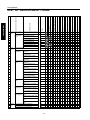
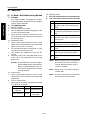
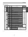
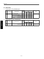
2. ADJUSTMENT
HOW TO USE THIS SECTION ................................ 2-1
[1]
Scope and Precautions ............................. 2-1
ADJUSTMENTS MADE WHEN REPLACING
PARTS...................................................................... 2-1
[1]
[How to Read Tables] ................................ 2-1
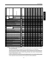
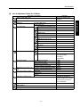
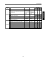
LIST OF ADJUSTMENT ITEMS ............................... 2-2
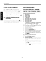
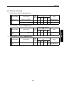
LCD ADJUSTMENT ................................................. 2-4
[1]
LCD Control Panel Adjustment.................. 2-4
[2]
LCD Panel Contrast/Key Sound
Adjustment................................................. 2-4
SETTINGS AND ADJUSTMENTS MADE WITH
THE P FUNCTION.................................................... 2-4
[1]
Checking and Printing the P Function ....... 2-4
[2]
Setting up the P Function .......................... 2-4
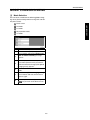
MODE CHANGING MENU ....................................... 2-5
[1]
Mode Selection.......................................... 2-5
25 MODE .................................................................. 2-6
[1]
Setting the 25 Mode .................................. 2-6
[2]
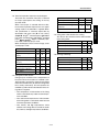
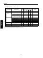
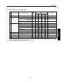
List of Adjustment Items for 25 Mode ........ 2-7
[3]
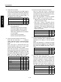
Setting Software DIP Switches.................. 2-8
[4]
Setting the Paper Size............................. 2-20
[5]
PM Count Resetting ................................ 2-22
[6]
Setting the PM Cycle ............................... 2-22
[7]
Collecting Data ........................................ 2-23
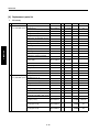
[8]
Copy Count by Parts to be Replaced
(Fixed Parts) ............................................ 2-38
[9]
Copy Count by Parts to be Replaced
(Optional Parts) ....................................... 2-43
[10] Setting Passwords................................... 2-44
[11] Setting the Telephone Number and/or
Fax Number of the Service Center .......... 2-45
[12] Setting the Serial Number ....................... 2-46
[13] Displaying the ROM Version ................... 2-46
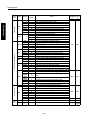
36 MODE ................................................................ 2-47
[1]
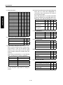
Setting Method ........................................ 2-47
[2]
High Voltage Adjustment ......................... 2-47
[3]
Changing Grid Voltage Adjustment ......... 2-48
[4]
Drum Peculiarity Adjustment ................... 2-49
[5]
Drum Peculiarity Adjustment (Manual) .... 2-55
[6]
User Paper Setting .................................. 2-55
[7]
Recall Standard Data
(Process Adjustment) .............................. 2-56
[8]
Tray Adjustment ...................................... 2-56
[9]
Magnification Adjustment ........................ 2-57
[10] Timing Adjustment................................... 2-60
[11] RADF Adjustment.................................... 2-64
[12] Centring Adjustment ................................ 2-66
[13] Distortion adjustment (Copier)................. 2-69
[14] Non-original automatic erasure
installation research................................. 2-69
[15] Recall standard data (Image adjustment) 2-70
[16] Running Test Mode ................................. 2-71
[17] Test pattern output mode ........................ 2-71
[18] Test pattern density setting ..................... 2-78
[19] Finisher adjustment ................................. 2-78
[20] List Output Mode ......................................2-82
[21] Tandem initial setting ...............................2-83
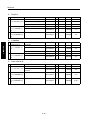
47 MODE.................................................................2-84
[1]
47 Mode / Multi Mode Setting Method .....2-84
[2]
Adjustment Data Display ..........................2-86
[3]
Hard Disk Check ......................................2-86
[4]
Input checklist ..........................................2-87
[5]
Output checklist........................................2-92
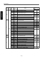
OTHER ADJUSTMENT...........................................2-97
[1]
Centring Adjustment.................................2-97
[2]
Skew adjustment (Main body) ................2-100
[3]
Adjusting the LCT Paper Feed Roller
Pressure (C-404 only) ............................2-100
[4]
Paper up/down plate horizontal
adjustment (LCT only) ............................2-101
[5]
Skew adjustment (LCT only) ..................2-103
[6]
Tray spring pressure adjustment............2-104
[7]
Paper feed height (upper limit)
adjustment (LCT only) ............................2-106
[8]
Pick-up release amount
adjustment (LCT only) ............................2-107
[9]
RADF mounting position adjustment......2-108
[10] RADF Skew adjustment .........................2-109
[11] RADF paper skew adjustment ...............2-110
[12] FNS Adjusting the magnets on the
by-pass conveyance guide plate ............2-112
[13] FNS adjusting the by-pass gate .............2-113
[14] FNS Adjusting the Shift Position ............2-115
[15] FNS Adjusting the paper exit solenoid ...2-116
[16] FNS Adjusting the mount location
of the paper exit arm ..............................2-117
[17] FNS Adjusting the mount location
of the alignment plates / U .....................2-118
[18] FNS Adjusting the mount location
of the alignment plates / L (FN-6 only) ...2-119
[19] FNS Adjusting the stapling position
(Flat stapling) .........................................2-120
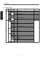
[20] FNS Adjusting the stapler vertical
positioning ..............................................2-121
[21] FNS Adjusting the stapling position
(stapling-and-folding) (FN-6 only) ..........2-123
[22] FNS Adjusting the angle of the folding
stopper (FN-6 only) ................................2-124
[23] FNS Adjusting the folding force
(FN-6 only) .............................................2-125
[24] FNS Adjusting the three-holding positions
(FN-6 only) .............................................2-126
[25] PK Adjusting the tilt of the punch hole
position ...................................................2-127
[26] PK Adjusting the punch hole vertical
position ...................................................2-128
[27] PI Centering Adjustment ........................2-129
SERVICE SCHEDULE.............................................. 3-1
[1]
Service Schedule....................................... 3-1
[2]
Maintenance Items .................................... 3-2
[3]
Main Body Periodic Inspection Items....... 3-10
[4]
RADF ...................................................... 3-12
[5]
FNS ......................................................... 3-13
[6]
LCT ......................................................... 3-14
[7]
PI ............................................................ 3-15
[8]
Replacement parts list ............................. 3-16
COPY MATERIALS ................................................ 3-19
[1]
Single unit supply .................................... 3-19
SERVICE MATERIAL LIST..................................... 3-20
[6]
[7]
Rewriting procedure after an error
interruption .................................................5-4
Connecting to the ISW connector...............5-4
3 DIS./ASSEMBLY
1
3. SERVICE
3 2DIS./ASSEMBLY
ADJUSTMEN
CONTENTS
APPENDIX
[1]
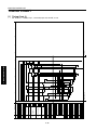
Overall Wiring Diagram..............................A-1
5. ISW
What's ISW? ............................................................. 5-1
SETUP ...................................................................... 5-2
[1]
ISW-compatible boards ............................. 5-2
[2]
Data flow.................................................... 5-2
[3]
Prepare the copier to start an ISW
transfer ...................................................... 5-2
[4]
Preparing the copier to transfer ................. 5-3
[5]
Relationships between processing states
and operational LEDs ................................ 5-3
4 ELECTRIC
3 DIS./ASSEMBLY
PARTS LIST
3 DIS./ASSEMBLY
5 ISW
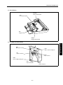
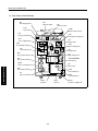
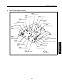
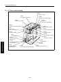
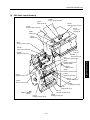
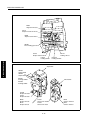
Parts Layout Drawing................................................ 4-1
[1]
Parts Layout Drawing ................................ 4-1
[2]
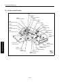
RADF Parts Layout Drawing...................... 4-9
[3]
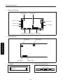
LCT Parts Layout Drawing....................... 4-10
[4]
FNS Parts Layout Drawing ...................... 4-11
[5]
PI Parts Layout Drawing .......................... 4-14
[6]
PK Parts Layout Drawing......................... 4-15
Connector Layout Drawing ..................................... 4-16
[1]
Connector Layout Drawing ...................... 4-16
[2]
LCT Connector Layout Drawing .............. 4-20
[3]
FNS Connector Layout Drawing .............. 4-20
[4]
PI Connector Layout Drawing.................. 4-21
[5]
PK Connector Layout Drawing ................ 4-21
Jam Code List ......................................................... 4-22
Error Code List........................................................ 4-32
Timing chart ............................................................ 4-48
[1]
Timing Chart (1)....................................... 4-48
[2]
Timing Chart (2)....................................... 4-49
[3]
RADF Timing Chart (1) ............................ 4-50
[4]
RADF Timing Chart (2) ............................ 4-51
[5]
LCT Time Chart ....................................... 4-52
[6]
FNS TIming Chart (1) .............................. 4-53
[7]
FNS Timing Chart (2)............................... 4-54
[8]
FNS Timing Chart (3)............................... 4-55
3 DIS./ASSEMBLY
3 SERVICE
4. ELECTRIC PARTS LIST
3 DIS./ASSEMBLY
5 ISW
4 ELECTRIC
3 DIS./ASSEMBLY
PARTS LIST
3 DIS./ASSEMBLY
3 SERVICE
3 2DIS./ASSEMBLY
ADJUSTMEN
3 DIS./ASSEMBLY
1
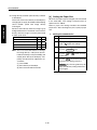
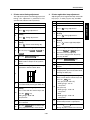
SAFETY AND IMPORTANT WARNING ITEMS
SAFETY AND IMPORTANT WARNING ITEMS
Read carefully the Safety and Important Warning Items described below to understand them before doing service work.
IMPORTANT NOTICE
Because of possible hazards to an inexperienced person servicing this copier as well as the risk of damage to
the copier, Minolta Corporation strongly recommends that all servicing be performed only by Minolta-trained service technicians.
Changes may have been made to this copier to improve its performance after this Service Manual was printed.
Accordingly, Minolta Corporation does not warrant, either explicitly or implicitly, that the information contained in
this Service Manual is complete and accurate.
The user of this Service Manual must assume all risks of personal injury and/or damage to the copier while servicing the copier for which this Service Manual is intended.
Therefore, this Service Manual must be carefully read before doing service work both in the course of technical
training and even after that, for performing maintenance and control of the copier properly.
Keep this Service Manual also for future service.
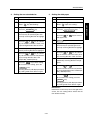
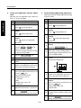
DANGER, WARNING, AND CAUTION SYMBOLS AND
EXPRESSIONS
In this Service Manual, each of three expressions "
DANGER," "
WARNING," and "
CAUTION" is defined
as follows together with a symbol mark to be used in a limited meaning.
When servicing the copier, the relevant works (disassembling, reassembling, adjustment, repair, maintenance,
etc.) need to be conducted with utmost care.
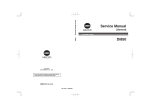
DANGER :Action having a high possibility of suffering death or serious injury
WARNING :Action having a possibility of suffering death or serious injury
CAUTION :Action having a possibility of suffering a slight wound, medium trouble, and property
damage
Symbols used for important warning items are defined as follows:
:Precaution
:Prohibition
:Direction
General precaution
Electric shock
Heated surface
General prohibition
Do not touch with wet hand
Do not disassemble
General instruction
Unplug
Ground/Earth
SAFETY WARNINGS
S-1
SAFETY AND IMPORTANT WARNING ITEMS
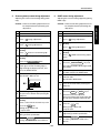
[1]
MODIFICATIONS NOT AUTHORIZED BY Minolta
Minolta copiers are renowned for their high reliability. This reliability is achieved through high-quality design and
a solid service network.
Copier design is a highly complicated and delicate process where numerous mechanical, physical, and electrical
aspects have to be taken into consideration, with the aim of arriving at proper tolerances and safety factors. For
this reason, unauthorized modifications involve a high risk of degradation in performance and safety. Such modifications are therefore strictly prohibited. the points listed below are not exhaustive, but they illustrate the reasoning behind this policy.
PROHIBITED ACTIONS:
• Using any cables or power cord not specified by Minolta.
• Using any fuse or thermostat not specified by Minolta. Safety will not be
assured, leading to a risk of fire and injury.
• Disabling fuse functions or bridging fuse terminals with wire, metal clips, solder or similar object.
• Disabling relay functions (such as wedging paper between relay contacts)
• Disabling safety functions (interlocks, safety circuits, etc.) Safety will not be
assured, leading to a risk of fire and injury.
• Making any modification to the copier unless instructed by Minolta
• Using parts not specified by Minolta
S-2
SAFETY AND IMPORTANT WARNING ITEMS
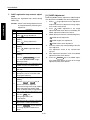
[2]
CHECKPOINTS WHEN PERFORMING ON-SITE SERVICE
Minolta copiers are extensively tested before shipping, to ensure that all applicable safety standards are met, in
order to protect the customer and customer engineer (hereafter called the CE) from the risk of injury. However, in
daily use, any electrical equipment may be subject to parts wear and eventual failure. In order to maintain safety
and reliability, the CE must perform regular safety checks.
1.Power Supply
WARNING: Wall Outlet
• Check that mains voltage is as specified. Plug the power cord into the dedicated wall outlet with a capacity greater than the maximum power consumption.
If excessive current flows in the wall outlet, fire may result.
• If two or more power cords can be plugged into the wall outlet, the total load
must not exceed the rating of the wall outlet.
If excessive current flows in the wall outlet, fire may result.
WARNING: Power Plug and Cord
• Make sure the power cord is plugged in the wall outlet securely.
Contact problems may lead to increased resistance, overheating, and the
risk of fire.
• Check whether the power cord is damaged. Check whether the sheath is
damaged.
If the power plug, cord, or sheath is damaged, replace with a new power
cord (with plugs on both ends) specified by Minolta. Using the damaged
power cord may result in fire or electric shock.
• When using the power cord (inlet type) that came with this copier, be sure to
observe the following precautions:
a.
Make sure the copier-side power plug is securely inserted in the socket
on the rear panel of the copier.
Secure the cord with a fixture properly.
b.
If the power cord or sheath is damaged, replace with a new power cord
(with plugs on both ends) specified by Minolta.
If the power cord (inlet type) is not connected to the copier securely, a
contact problem may lead to increased resistance, overheating, and risk
of fire.
• Check whether the power cord is not stepped on or pinched by a table and
so on.
Overheating may occur there, leading to a risk of fire.
S-3
kw
SAFETY AND IMPORTANT WARNING ITEMS
WARNING: Power Plug and Cord
• Do not bundle or tie the power cord.
Overheating may occur there, leading to a risk of fire.
• Check whether dust is collected around the power plug and wall outlet.
Using the power plug and wall outlet without removing dust may result in
fire.
• Do not insert the power plug into the wall outlet with a wet hand.
The risk of electric shock exists.
• When unplugging the power cord, grasp the plug, not the cable.
The cable may be broken, leading to a risk of fire and electric shock.
WARNING: Wiring
• Never use multi-plug adapters to plug multiple power cords in the same outlet.
If used, the risk of fire exists.
• When an extension cord is required, use a specified one.
Current that can flow in the extension cord is limited, so using a too long
extension cord may result in fire.
Do not use an extension cable reel with the cable taken up. Fire may
result.
WARNING: Ground Lead
• Check whether the copier is grounded properly.
If current leakage occurs in an ungrounded copier, you may suffer electric
shock while operating the copier. Connect the ground lead to one of the
following points:
a. Ground terminal of wall outlet
b. Ground terminal for which Class D work has been done
S-4
SAFETY AND IMPORTANT WARNING ITEMS
WARNING: Ground Lead
• Pay attention to the point to which the ground lead is connected.
Connecting the ground lead to an improper point such as the points listed
below results in a risk of explosion and electric shock:
a. Gas pipe (A risk of explosion or fire exists.)
b. Lightning rod (A risk of electric shock or fire exists.)
c. Telephone line ground (A risk of electric shock or fire exists in the case
of lightning.)
d. Water pipe or faucet (It may include a plastic portion.)
2.Installation Requirements
WARNING: Prohibited Installation Place
• Do not place the copier near flammable materials such as curtains or volatile
materials that may catch fire.
A risk of fire exists.
• Do not place the copier in a place exposed to water such as rain water.
A risk of fire and electric shock exists.
WARNING: Nonoperational Handling
• When the copier is not used over an extended period of time (holidays, etc.),
switch it off and unplug the power cord.
Dust collected around the power plug and outlet may cause fire.
CAUTION: Temperature and Humidity
• Do not place the copier in a place exposed to direct sunlight or near a heat
source such as a heater.
A risk of degradation in copier performance or deformation exists.
Do not place the copier in a place exposed to cool wind.
Recommended temperature and humidity are as follows:
Temperature: 10°C to 30°C
Humidity: 10% to 80% (no dew condensation)
Avoid other environments as much as possible.
CAUTION: Ventilation
• Do not place the copier in a place where there is much dust, cigarette smoke,
or ammonia gas.
Place the copier in a well ventilated place to prevent machine problems
and image faults.
S-5
SAFETY AND IMPORTANT WARNING ITEMS
CAUTION: Ventilation
• The copier generates ozone gas during operation, but it is not sufficient to be
harmful to the human body.
If a bad smell of ozone is present in the following cases, ventilate the
room.
a. When the copier is used in a poorly ventilated room
b. When taking a lot of copies
c. When using multiple copiers at the same time
CAUTION: Vibration
• When installing the copier, read the Installation Guide thoroughly. Be sure to
install the copier in a level and sturdy place.
Constant vibration will cause problems.
• Be sure to lock the caster stoppers.
In the case of an earthquake and so on, the copier may slide, leading to a
injury.
CAUTION: Inspection before Servicing
• Before conducting an inspection, read all relevant documentation (Service
Manual, technical notices, etc.) and proceed with the inspection following the
prescribed procedure, using only the prescribed tools. Do not make any
adjustment not described in the documentation.
If the prescribed procedure or tool is not used, the copier may break and a
risk of injury or fire exists.
• Before conducting an inspection, be sure to disconnect the power plugs from
the copier and options.
When the power plug is inserted in the wall outlet, some units are still powered even if the POWER switch is turned OFF. A risk of electric shock
exists.
• The area around the fixing unit is hot.
You may get burnt.
DANGER: Work Performed with the Copier Powered
• Take every care when making adjustments or performing an operation check
with the copier powered.
If you make adjustments or perform an operation check with the external
cover detached, you may touch live or high-voltage parts or you may be
caught in moving gears or the timing belt, leading to a risk of injury.
S-6
SAFETY AND IMPORTANT WARNING ITEMS
DANGER: Work Performed with the Copier Powered
• Take every care when servicing with the external cover detached.
High-voltage exists around the drum unit. A risk of electric shock exists.
WARNING: Safety Checkpoints
• Check the exterior and frame for edges, burrs, and other damages.
The user or CE may be injured.
• Do not allow any metal parts such as clips, staples, and screws to fall into the
copier.
They can short internal circuits and cause electric shock or fire.
• Check wiring for squeezing and any other damage.
Current can leak, leading to a risk of electric shock or fire.
• When disconnecting connectors, grasp the connector, not the cable.
(Specifically, connectors of the AC line and high-voltage parts)
Current can leak, leading to a risk of electric shock or fire.
• Carefully remove all toner remnants and dust from electrical parts and electrode units such as a charging corona unit.
Current can leak, leading to a risk of copier trouble or fire.
• Check high-voltage cables and sheaths for any damage.
Current can leak, leading to a risk of electric shock or fire.
WARNING: Safety Checkpoints
• Check electrode units such as a charging corona unit for deterioration and
sign of leakage.
Current can leak, leading to a risk of trouble or fire.
• Before disassembling or adjusting the write unit incorporating a laser, make
sure that the power cord has been disconnected.
The laser light can enter your eye, leading to a risk of loss of eyesight.
• Do not remove the cover of the write unit. Do not supply power with the write
unit shifted from the specified mounting position.
The laser light can enter your eye, leading to a risk of loss of eyesight.
• When replacing a lithium battery, replace it with a new lithium battery specified in the Parts Guide Manual. Dispose of the used lithium battery using the
method specified by local authority.
Improper replacement can cause explosion.
S-7
SAFETY AND IMPORTANT WARNING ITEMS
WARNING: Safety Checkpoints
• After replacing a part to which AC voltage is applied (e.g., optical lamp and
fixing lamp), be sure to check the installation state.
A risk of fire exists.
• Check the interlock switch and actuator for loosening and check whether the
interlock functions properly.
If the interlock does not function, you may receive an electric shock or be
injured when you insert your hand in the copier (e.g., for clearing paper
jam).
• Make sure the wiring cannot come into contact with sharp edges, burrs, or
other pointed parts.
Current can leak, leading to a risk of electric shock or fire.
• Make sure that all screws, components, wiring, connectors, etc. that were
removed for safety check and maintenance have been reinstalled in the original location. (Pay special attention to forgotten connectors, pinched cables,
forgotten screws, etc.)
A risk of copier trouble, electric shock, and fire exists.
HANDLING OF MATERIALS FOR SERVICING
• Unplug the power cord from the wall outlet.
Drum cleaner (isopropyl alcohol) and roller cleaner (acetone-based) are
highly flammable and must be handled with care. A risk of fire exists.
• Do not replace the cover or turn the copier ON before any solvent remnants
on the cleaned parts have fully evaporated.
A risk of fire exists.
• Use only a small amount of cleaner at a time and take care not to spill any
liquid. If this happens, immediately wipe it off.
A risk of fire exists.
• When using any solvent, ventilate the room well.
Breathing large quantities of organic solvents can lead to discomfort.
S-8
SAFETY AND IMPORTANT WARNING ITEMS
DANGER: HANDLING OF MATERIALS FOR SERVICING
• Toner and developer are not harmful substances, but care must be taken not
to breathe excessive amounts or let the substances come into contact with
eyes, etc. It may be stimulative.
If the substances get in the eye, rinse with plenty of water immediately.
When symptoms are noticeable, consult a physician.
• Never throw the used cartridge and toner into fire.
You may be burned due to dust explosion.
[3]
CONCLUSION
1. Safety of users and customer engineers depends highly on accurate maintenance and administration.
Therefore, safety can be maintained by the appropriate daily service work conducted by the customer
engineer.
2. When performing service, each copier on the site must be tested for safety. The customer engineer must
verify the safety of parts and ensure appropriate management of the equipment.
S-9
SAFETY AND IMPORTANT WARNING ITEMS
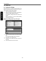
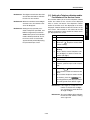
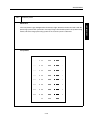
SAFETY CIRCUITS
[2]
This machine is provided with the following safety circuits to prevent machine faults from resulting in seri-
Protection by L2 and L3 (fixing heater
lamps) overheating prevention circuit
ous accidents.
[1]
Overall protection circuit
[2]
L2 and L3 (fixing heater lamps) overheating
DCPS
TS1
prevention circuit
RL1
PRCB
These safety circuits are described below to provide
the service engineer with a renewed awareness of
TH2
RL1
them in order to prevent servicing errors that may
impair their functions.
Control
section
Overall Protection Circuit
L2
AC driver
section
TH1
[1]
TS2
L3
L4
CBR1
1.
Protection by software
The output voltage from TH1 (fixing tempera-
NF
ture sensor 1) is read by the CPU. If this voltage is abnormal, L2 (fixing heater lamp 1), L3
CBR2
(fixing heater lamp 2), and RL1 (main relay)
are turned OFF.
1.
Protection by CBR1 and CBR2 (circuit
CAUTION:
Do not change the gap between the roller
breakers)
CBR1 and CBR2 interrupt the AC line instantaneously when an excessive current flows due
and TH1. When replacing TH1, check the
to a short in the AC line.
function must not be deactivated under
any circumstances.
specified mounting dimensions. The RL1
CAUTION:
The CBR1 and CBR2 functions must not
be deactivated under any circumstances.
S-10
SAFETY AND IMPORTANT WARNING ITEMS
2.
Protection by the hardware circuit
The output voltages from TH1 and TH2 (fixing
temperature sensors) are compared with the
abnormality judgment reference value in the
comparator circuit. If the output voltage from
TH1 or TH2 exceeds the reference value, L2
(fixing heater lamp 1), L3 (fixing heater lamp
2), RL1 (main relay) are turned OFF in hardware means.
CAUTION:
Periodically check the TH2 face contacting the roller, and replace TH2 if any
abnormality is detected.
Since TH1 (fixing temperature sensor)
face does not contact the roller, check the
distance from the roller and the sensor
orientation if any abnormality is detected.
The RL1 function must not be deactivated
3.
under any circumstances.
Protection by TS1 (thermostat/U) and TS2
(thermostat/L)
When the temperature of the fixing roller
(upper/lower) exceeds the specified value, TSs
are turned OFF, thus interrupting the power to
L2 (fixing heater lamp/1), L3 (fixing heater
lamp/2), and L4 (fixing heater lamp/3) directly.
CAUTION:
Do not use any other electrical conductor
in place of TS1 and TS2. Do not change
the distance between the roller and TS
(thermostat).
S-11
SAFETY AND IMPORTANT WARNING ITEMS
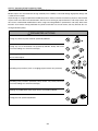
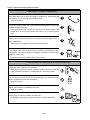
INDICATION OF WARNING ON THE MACHINE
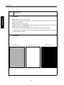
Caution labels shown below are attached in some areas on/in the machine.
When accessing these areas for maintenance, repair, or adjustment, special care should be taken to avoid burns
and electric shock.
CAUTION
DO NOT INSERT your
finger into the two
RADF hinge portions; otherwise you
may be injured.
CAUTION
ATTENTION
VORSICHT
PRECAUCION
ATTENZIONE
CAUTION
High temperature!
Do not touch. Use care
when clearing paper.
ATTENTION
Temp rature lev e!
Risque de br lure. Soyez
prudent en retirant la
feuille coinc e.
VORSICHT
Hei§e OberflŠche!
Brandverletzungsgefahr.
Bei Beseitigung von
Papierstaus vorsichtig
vorgehen.
PRECAUCION
ÁTemperatura alta!
No tocar. Tener cuidado al
remover el papel.
ATTENZIONE
Alta temperatura!
Non toccare. Agire con
prudenza nel rimuovere la
carta.
WARNING
This area generates high
voltage. If touched, electrical shock may occur.
DO NOT TOUCH.
CAUTION
The fixing unit is
very hot. To avoide
getting burned, DO
NOT TOUCH.
CAUTION
The conveyance fixing unit is heavy. Use
care and draw it out
gently; otherwise you
may be injured.
CAUTION
Please adhere to all caution labels to avoid burns or injury.
S-12
CAUTION
ATTENTION
VORSICHT
PRECAUCION
ATTENZIONE
CAUTION
DO NOT put your hand
between the main body and
developing fixing unit; otherwise you may be injured.
SAFETY AND IMPORTANT WARNING ITEMS
(Finisher with Cover Inserter B only)
CAUTION
DO NOT insert your finger into the bottom of the
feeder upper part when returning to its original
position; otherwise you may be injured.
(All trays)
CAUTION
DO NOT put your hand
between the main body and
tray; otherwise you may be
injured.
(FN-6/FN-112 Finisher)
CAUTION
Use care after opening the
paper exit outlet. DO NOT put
your hand into it; otherwise
you may be injured.ured.
(FN-6 Finisher only)
CAUTION
Inside the lower paper exit outlet is
the roller drive unit. DO NOT put
your hand into it; otherwise you
may be injured.
CAUTION
Please adhere to all caution labels to avoid burns or injury.
S-13
SAFETY AND IMPORTANT WARNING ITEMS
<SCANNER SECTION>
<WRITE UNIT>
<REAR COVER>
CAUTION
Please adhere to all caution labels to avoid burns or injury.
S-14
3 DIS./ASSEMBLY
1
1
DISASSEMBLY/ASSEMBLY
3 DIS./ASSEMBLY
1
This section explains how to disassemble and reassemble the machine.
When disassembling and reassembling the machine, follow the precautions given below.
1. Be sure the power cord has been unplugged from the wall outlet.
2. The disassembled parts must be reassembled following the disassembly procedure in reverse unless otherwise specified.
3. Care should be taken not to lose small parts. Care should also be
taken not to install small parts in wrong places.
4. Do not operate the machine before installing all the disassembled
parts completely.
5. Removal of some screws is prohibited in this section. Never loosen
them.
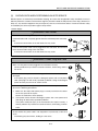
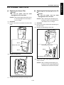
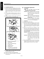
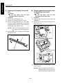
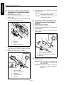
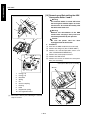
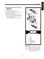
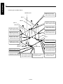
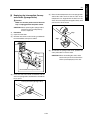
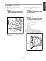
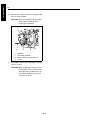
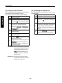
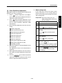
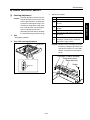
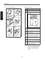
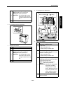
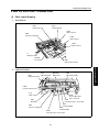
EXTERNAL SECTION
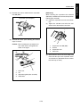
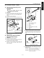
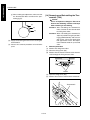
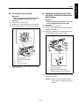
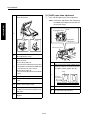
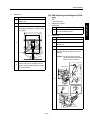
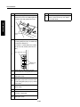
[1] Replacing the Ozone Filter
Caution:
Be sure the power cord has been
unplugged from the wall outlet.
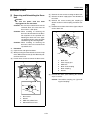
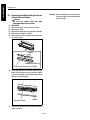
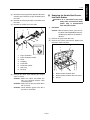
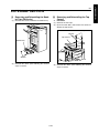
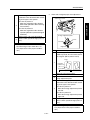
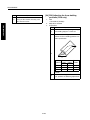
[2] Replacing the Developing Suction Filter
Caution: When replacing the ozone filter, insert
it in the opening in the main body as
far as it will go.
a. Procedure
(1) Loosen two screws to remove the ozone filter
cover.
Caution:
Be sure the power cord has been
unplugged from the wall outlet.
Caution: When replacing the developing suction filter, insert it in the opening in the
main body as far as it will go.
a. Procedure
(1) Loosen the screw to remove the developing suction filter cover.
(2) Replace the developing suction filter.
Screw
Developing suction filter
Ozone filter cover
Screw
Screw
(2) Replace the ozone filter.
Ozone filter
Developing suction filter cover
(3) Reinstall the above parts following the removal
steps in reverse.
Caution: When installing the developing suction filter, the filter-supporting material
should face the back of the machine.
Ozone filter cover
(3)
Reinstall the above parts following the removal steps in reverse.
1-A-1
3 DIS./ASSEMBLY
1
EXTERNAL SECTION
3 DIS./ASSEMBLY
1
EXTERNAL SECTION
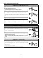
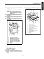
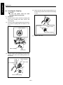
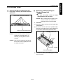
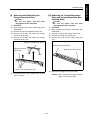
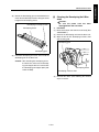
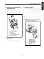
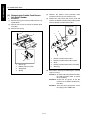
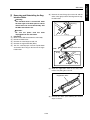
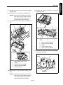
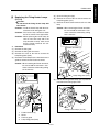
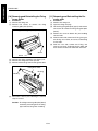
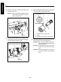
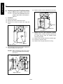
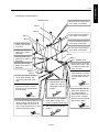
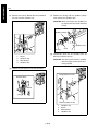
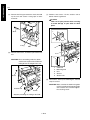
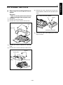
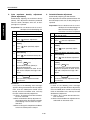
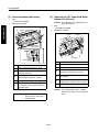
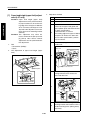
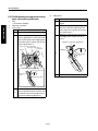
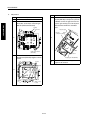
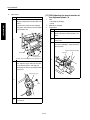
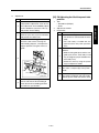
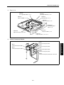
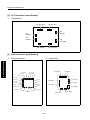
[3] Removing and Reinstalling the External Covers
Caution:
Be sure the power cord has been
unplugged from the wall outlet.
a. Procedure
(1) Remove fourteen screws to detach the rear
cover.
(2) Remove seven screws to detach the left side
cover.
1
2
2
Caution: The ozone filter cover and the option
cover detach together with the rear
cover.
1
4
2
2
4
2
1.
2.
4
4
4
1.
2.
3.
4.
3
Option cover
Ozone filter cover
Rear cover
Screws
1-A-2
Left side cover
Screws
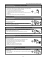
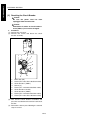
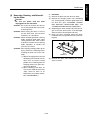
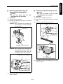
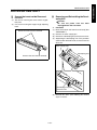
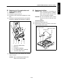
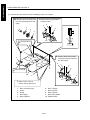
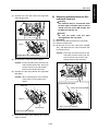
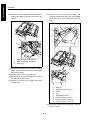
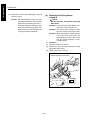
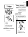
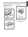
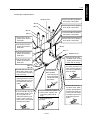
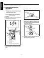
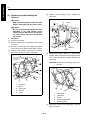
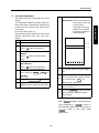
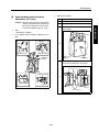
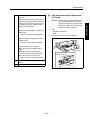
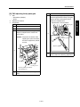
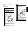
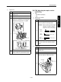
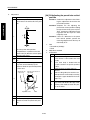
(3) Loosen one screw and remove the developing
suction filter cover.
(4) Loosen five screws and detach the right side
cover (upper).
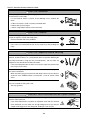
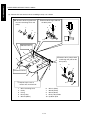
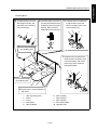
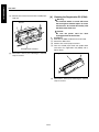
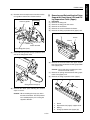
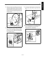
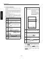
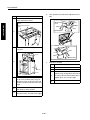
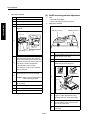
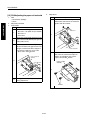
(14) Remove the top cover (middle front) and top
cover (middle rear).
2
Caution: The developing suction filter cover
detaches together with the right side
cover (upper).
(5) Loosen two screws to detach the right side cover
(lower front).
(6) Loosen two screws to detach the right side cover
(lower rear).
(7) Loosen two screws to detach the right side cover
(lower middle).
8
3
4
1
9
9
1
2
8
6
5
7
1.
2.
3.
4.
5.
6.
7.
8.
9.
6
6
3
6
5
1.
2.
3.
4.
5.
6.
4
6
Right side cover (upper)
Developing suction filter cover
Right side cover (lower rear)
Right side cover (lower middle)
Right side cover (lower front)
Screws
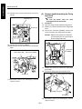
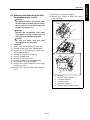
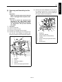
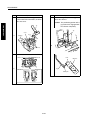
(8) Open the RADF.
(9) Remove the two shoulder screws to remove the
original stopper plate (left).
(10) Remove the three shoulder screws to remove the
original stopper plate (rear).
(11) Remove the platen glass.
(12) Remove two screws to detach the top cover (left).
(13) Remove two screws to detach the top cover
(right).
1-A-3
6
Top cover (left)
Top cover (middle rear)
Original stopper plate (rear)
Top cover (right)
Top cover (middle front)
Platen glass
Original stopper plate (left)
Shoulder screws
Screws
3 DIS./ASSEMBLY
1
EXTERNAL SECTION
3 DIS./ASSEMBLY
1
EXTERNAL SECTION
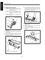
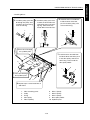
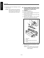
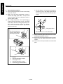
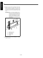
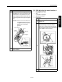
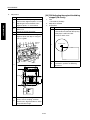
(15) Open the front right door and front left door.
(16) Remove two screws to remove the front right
door hinge (lower) and front right door.
(17) Remove two screws and remove the front left
door hinge (lower) and the front left door.
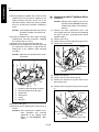
[4] Changing the Operation Panel
Attachment Angle and Removing/
Reinstalling
Caution:
Be sure the power cord has been
unplugged from the wall outlet.
a. Procedure
(1) Open the front left door and front right door.
(2) Remove two screws to remove the operation
panel cover (middle).
Operation panel cover (middle)
5
1
2
Screws
3
(3) Remove two screws to unlock the operation
panel.
5
Screws
Operation panel
Screws
4
1.
2.
3.
4.
5.
Front right door
Front right door hinge (lower)
Front left door hinge (lower)
Front left door
Screws
(18) Reinstall the above parts following the removal
steps in reverse.
1-A-4
Attachment holes when changing
the operation panel angle
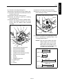
(4) When changing the operation panel attachment
angle, align the operation panel stopper with the
stopper hole at the front side on the bottom of the
operation panel and fasten using two screws in
the operation cover attachment holes.
Caution1: To remove the operation panel, skip
this step and proceed to step (5).
Caution2: When the attachment angle of the
operation panel is changed, the
operation panel cover and two
screws will become unnecessary.
(5) Remove the relay connectors (CN163, 164).
Caution: Each relay connector consist of two
male sides and one female side. Be
sure to remove only the male side
(shown below).
(6) Remove screws to remove the Ground terminal.
(7) Remove the operation panel.
5
3
2
5
1
1
1
2
1
4
3
1.
2.
3.
4.
5.
Ground terminal
Relay connectors (CN163)
Relay connectors (CN164)
Operation panel
Screws
1
(8) Reinstall the above parts following the removal
steps in reverse.
4
2
1.
2.
3.
4.
Stopper hole
Operation panel stopper
Operation panel
Screws
1-A-5
3 DIS./ASSEMBLY
1
EXTERNAL SECTION
3 DIS./ASSEMBLY
1
EXTERNAL SECTION
[5] Resetting the Circuit Breaker
Caution:
Be sure the power cord has been
unplugged from the wall outlet.
Caution:
Connection of cables to circuit breaker 1
and 2 (CBR1, 2) must not be changed.
a. Procedure
(1) Remove the rear cover.
(2) Remove two screws and loosen the circuit
breaker assembly.
1
2
3
4
5
6
7
9
1.
2.
3.
4.
5.
6.
7.
8.
9.
8
Noise filter (NF)
Faston (FT3: noise filter side/black cable)
Circuit breaker 1 (CBR1)
Screws (2)
Faston (FT1: wall outlet side/black cable)
Circuit breaker assembly
Circuit breaker 2 (CBR2)
Faston (FT2: wall outlet side/white cable)
Faston (FT4: noise filter side/white cable)
(3) Turn over the circuit breaker assemblies and
press the reset button at the center of each circuit
breaker.
(4) Reinstall the above parts following the removal
steps in reverse.
1-A-6
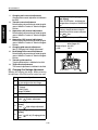
DRIVE SECTION
[1] Removing and Reinstalling the Drum
Motor(M2)
Caution:
Be sure the power cord has been
unplugged from the wall outlet.
a.
(1)
(2)
(3)
(4)
Caution: Be sure to draw the drum unit out of
the main body before removing or
reinstalling the drum drive motor. If
you fail to draw out the drum unit, the
cleaning blade may be damaged
because the drum rotates when
installing or removing the flywheel or
gear.
Procedure
Draw the drum unit out of the main body. (See
"DRUM UNIT.")
Remove the rear cover. (See "EXTERNAL SECTION.")
Remove the developing suction cover and right
cover (top). (See "EXTERNAL SECTION.")
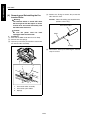
Remove twenty-one screws and remove the
image control board cover.
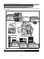
(5) Remove five screws at the rear and three screws
on the right side and remove all connectors from
the image control board (ICB).
Screws (3)
Image control board (ICB)
Screws (3)
Screws (2)
Image control board mounting plate
(6) Remove each cable from wire guide.
(7) Remove one cable from the scanner board and
two cables from the write unit, draw then through
the hole and open the image control board
mounting plate.
Image control board cover
Screws (7)
Image control board mounting plate
Screws (5)
Screws (5)
Screws (4)
1-B-1
3 DIS./ASSEMBLY
1
DRIVE SECTION
3 DIS./ASSEMBLY
1
DRIVE SECTION
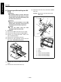
(8) Remove three screws and remove the two flywheels.
[2] Removing and Reinstalling the Fixing
Input Gear
Caution:
Be sure the power cord has been
unplugged from the wall outlet.
a. Procedure
(1) Open the image control bard mounting board.
(2) Remove six screws and remove the fixing motor
cover.
(3) Pull out the connector (CN304), remove four
screws to remove the fixing motor assembly.
Flywheels (2)
Screws (3)
Caution: Hold the fixing motor assembly with
your hand because it is connected to
the main body with cable.
Fixing motor assembly
Screws (4)
(9) Remove the connector (CN301).
(10) Remove four screws and remove the drum motor
(M2).
Connector
(CN304)
Drum motor (M2) Connector (CN301)
Fixing motor cover
Screws (6)
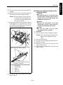
(4) Remove two screws to remove the fixing input
gear holder.
(5) Pull out the fixing input gear from the shaft.
Screws (4)
Fixing input gear holder
(11) Reinstall the above parts following the removal
steps in reverse.
Fixing input gear
Screws (2)
(6) Reinstall the above parts following the removal
steps in reverse.
1-B-2
SCANNER SECTION
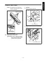
[1] Screws that Must not be Removed
a.
[2] Removing and Reinstalling the CCD
Unit
14 screws securing the CCD unit
Caution:
Be sure the power cord has been
unplugged from the wall outlet.
Screws that must not be removed
Caution: Be sure to adjust the image after
installing the CCD unit (See
"ADJUSTMENTS.")
a. Procedure
(1) Remove the right side cover (top), left side cover,
original stopper plates (left and rear), platen
glass and top cover (right, left, front center, and
rear center). (See "EXTERNAL SECTION.")
(2) Remove eleven screws to remove the lens light
blocking cover.
Screws that must not be removed
b.
Read position adjusting plate screw (1 each)
1
4
Screws
4
2
Lens light blocking cover
(3) Remove the connector (CN170) from the A/D
converter board (ADB).
CCD unit
4
3
1.
2.
3.
4.
Read position adjusting plate (left rear)
Read position adjusting plate (right rear)
Read position adjusting plate (left front)
Screws that must not be removed
Connector (CN170)r
A/D converter board (ADB)
1-C-1
3 DIS./ASSEMBLY
1
SCANNER SECTION
3 DIS./ASSEMBLY
1
SCANNER SECTION
(4) Remove two screws to remove the CCD unit.
[3] Replacing the Exposure Lamp
Caution1:
Be sure the power cord has been
unplugged from the wall outlet.
Screws
Caution2:
Do not touch the exposure lamp with bare
hands.
Marking
CCD unit
Marking
Caution: Mark the place where the CCD unit is
installed before removing it.
(5) Reinstall the above parts following the removal
steps in reverse.
Caution: Be sure to check the image after
installing the exposure lamp. (See
"ADJUSTMENTS.")
a. Procedure
(1) Remove the original stopper plates (left and
rear), platen glass and top cover (right, middle
front, and middle rear). (See "EXTERNAL SECTION.")
(2) Move the exposure unit to the notch in the main
body frame on the paper exit side.
(3) Remove the connector and two screws, then
remove the exposure lamp.
Screws
Connector
Screws
Exposure lamp
(4) Reinstall the above parts following the removal
steps in reverse.
1-C-2
[4] Removing and Reinstalling the Exposure Unit
Caution:
Be sure the power cord has been
unplugged from the wall outlet.
Caution1: When installing the exposure unit,
use the optics unit positioning jig.
Caution2: Be sure to perform image adjustment after installing the exposure
unit. (See "ADJUSTMENT.")
a. Procedure
(1) Remove the right side cover (top), left side cover,
original stopper plates (left and rear), platen
glass and top cover (right, left, front center, and
rear center). (See "EXTERNAL SECTION.")
(2) Remove the operation panel. (See "EXTERNAL
SECTION.")
(3) Remove the relay connector (CN162).
(6) Move the exposure unit to the notch in the main
body frame on the paper exit side.
(7) Remove two screws to detach the cord clamp
(B).
(8) Remove one screw to remove the ground terminal.
(9) Disconnect the connector (CN630).
(10) Remove four screws to detach the exposure unit.
1
2
3
Caution: Each relay connector consist of two
male sides and one female side. Be
sure to remove only the male side
(shown below) of the CN162 connector.
(4) Loosen the left and right screws on the operation
panel cover (top).
(5) Remove three screws and remove the operation
unit cover (top).
5
5
Relay connector
(CN162)
Operation panel cover
(top)
Screws
5
1.
2.
3.
4.
5.
6.
Screws (loosen)
Screws (loosen)
1-C-3
6
6
Optical wire fastener
Cord clamp (B)
Ground terminal
Connector (CN630)
Exposure unit
Screws
4
3 DIS./ASSEMBLY
1
SCANNER SECTION
3 DIS./ASSEMBLY
1
SCANNER SECTION
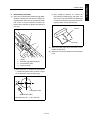
b. Installation procedure
(1) Move the V-mirror unit toward the paper exit side,
then insert the optics positioning jigs from the
front to secure the V-mirror unit. Ensure that the
optics positioning jigs pass through the V-mirror
unit.
(2) Insert the optics positioning jigs in the holes at
the exposure unit mounting position from the
front.
(3) Slide the exposure unit to the paper exit side until
it touches the optics unit positioning jig.
[5] Installing the Optics Wire
1
a.
(1)
(2)
2
4
3
(3)
5
6
7
3
8
1.
2.
3.
4.
5.
6.
7.
8.
(4)
Exposure unit fixing hole
Unused hole
Optics unit positioning jig
V-mirror unit
Stopping surface
Exposure unit
For exposure unit positioning
V-mirror unit fixing hole (left)
(4) Install the exposure unit to the optics wire mounting bracket with four screws.
(5) Remove two optics unit positioning jigs.
(6) Reverse the removal procedure to reinstall the
removed parts.
1-C-4
Caution:
Be sure the power cord has been
unplugged from the wall outlet.
Caution1: When winding the optics wire around
the pulley, be sure to run the wire
tightly so that it does not ride on the
side of the pulley.
Caution2: When re-tensioning or replacing the
optics wire, be sure to use the optics
positioning jig.
Caution3: Be sure to perform image adjustment after replacing or re-installing
the wire (See "ADJUSTMENT.")
Procedure
Remove the exposure unit.
Move the V-mirror unit toward the paper exit side
then insert the optics positioning jigs from the
front to secure the V-mirror unit. Ensure that the
optics positioning jigs pass through the V-mirror
unit.
Place the metal bead at the midpoint of each
optics wire in the mounting hole in the drive pulley. Starting at this point, wind the optics wire five
turns to the outside and four times to the inside
on the drive pulley.
Caution1: Ensure that there is a metal bead at
the end of the outer wire, and a wire
terminal at the end of the inner wire.
Caution2: Pull out the outer wire from above the
drive pulley in the paper exit direction, and the inner wire from under
the drive pulley in the paper feed
direction.
After winding the outer wire, secure it to the wire
stopper via the outside of pulley 1 and V-mirror
pulley through the notch in the wire stopper.
(3)
(4)
Four turns
(3)
Four turns
Rear
Front
1
Five turns
1
1
Five turns
2
3
10
3
5
2
9
7
10
4
2
11
6
(5) 8
4
Front
12
(7)
8
(6)
5
7
(4)
1
6
2
1.
2.
3.
4.
5.
6.
Metal bead
Wire stopper
Pulley 1
Drive pulley
V-mirror pulley
Pulley 2
7.
8.
9.
10.
11.
12.
Caution: There are two grooves in the wire
stopper. Ensure that the outer groove
is at the rear and the inner groove is at
the front.
(5) Reverse the inner wire at pulley 2, pass it along
the inside of the V-mirror pulley and pulley 3, then
attach the wire terminal to the spring fixing plate.
At this time, secure the spring fixing plate temporarily with one screw.
1-C-5
Pulley 3
Spring fixing plate
V-mirror unit
Exposure unit mounting piece
Spring
Screws
(6) Install the other wire following the same procedure.
(7) Loosen each screw that was tightened temporarily, install the spring on the spring fixing plate,
and tighten each screw.
3 DIS./ASSEMBLY
1
SCANNER SECTION
3 DIS./ASSEMBLY
1
SCANNER SECTION
[6] Cleaning the Slit Glass and Platen
Glass
Caution:
Be sure the power cord has been
unplugged from the wall outlet.
(1) Remove the original stopper plates (left and
rear), platen glass, and top cover (right, left, front
center, and rear center). (See "EXTERNAL SECTION.")
(2) Remove two screws to detach the slit glass.
(3) Place the removed slit glass and platen glass on
a rag and clean with drum cleaner and cleaning
pad.
Screws
Slit glass
Slit glass
Screws
(4) Reinstall the above parts following the removal
steps in reverse.
1-C-6
WRITE SECTION
[1] Removing and Reinstalling the Write
Unit
Warning:
(1) Do not energize the write unit when it is
not in the correct position.
(2) Never remove the write unit cover and
the polygon unit cover.
(3) Never look directly into the laser beam. It
can cause blindness.
(4) Never remove the write unit for at least
two minutes after turning OFF the main
switch.
Caution:
Be sure the power cord has been
unplugged from the wall outlet.
a. Procedure
(1) Remove the left side cover. (See "EXTERNAL
SECTION.")
(2) Remove nine screws to detach the fan holder
assembly.
(3) Remove the relay connector (CN338).
Caution: Each relay connector consists of two
male sides and one female side. Be
sure to remove only the male side
(shown below) of the CN338 connector.
Fan holder assembly
Relay connector (CN338)
Screws
(4) Remove the three connectors (CN185, 187,
188).
(5) Loosen the screw to draw out and remove the
write unit.
2
1
5
1.
2.
3.
4.
5.
3
4
Connector (CN187)
Connector (CN185)
Connector (CN188)
Write unit
Screw
(6) Reinstall the above parts following the removal
steps in reverse.
1-D-1
3 DIS./ASSEMBLY
1
WRITE SECTION
3 DIS./ASSEMBLY
1
WRITE SECTION
[2] Cleaning the Dust-proof Glass
Caution:
Be sure the power cord has been
unplugged from the wall outlet.
a. Procedure
(1) Remove the write unit.
(2) Clean the dust-proof glass at the bottom of the
write unit with cleaning pad and blower brush.
Write unit
Dust-proof glass
(3) Reinstall the above parts following the removal
steps in reverse.
1-D-2
DRUM UNIT
[1] Removing and Reinstalling the Drum
Unit
Caution:
Be sure the power cord has been
unplugged from the wall outlet.
Caution1: Be sure to put a drum cover over the
removed drum unit and store the
drum unit in a dark place.
Caution2: When installing or removing the
drum unit, do not rotate it in the direction opposite to the specified one.
Rotating the drum unit in the opposite direction during copy operation
could damage the cleaning blade.
Caution3: When installing or removing the
drum unit, take care not to touch the
separation claw.
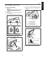
a. Procedure
(1) Open the left and right front doors.
(2) While pressing the solenoid release lever on top
of the ADU rack to the left, flip the ADU rack pullout lever to the left.
(3) Loosen three screws to remove the drum cover.
1
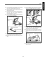
(4) Remove the two screws securing the drum unit.
(5) Release the toner supply pipe in the direction of
the arrow.
(6) Remove the screw securing the coupling to
detach the drum shaft coupling and drum coupling.
(7) Hold the two sections shown in the figure and pull
out the drum unit.
6
1
3
6
5
4
1.
2.
3.
4.
5.
6.
2
2
Drum unit
Toner supply pipe
Hold here
Drum shaft coupling
Drum coupling
Screws
(8) Reinstall the above parts following the removal
steps in reverse.
3
Caution: To install the coupling, see "[2] Installing the Coupling."
4
1.
2.
3.
4.
Drum cover
Screws
ADU rack pullout lever
Solenoid release lever
1-E-1
3 DIS./ASSEMBLY
1
DRUM UNIT
3 DIS./ASSEMBLY
1
DRUM UNIT
[2] Installing the Coupling
Caution:
Be sure the power cord has been
unplugged from the wall outlet.
a. Procedure
(1) Clean the outer surface of the drum coupling and
drum shaft coupling with drum cleaner and
cleaning pad.
(2) Insert the drum coupling aligning the protrusions
on the drum coupling with the notches in the
drum.
(4) Turn the head of the drum coupling clockwise so
that the flange section on the drum shaft coupling
is flush.
Drum shaft
Flange section
Drum notches
Drum shaft coupling
(5) Tighten with screw.
Drum coupling
Protrusions
(3) Insert the drum shaft coupling so that the D cut
section of the drum shaft coupling matches the
drum shaft.
Drum coupling
D cut section
Drum shaft
Drum shaft coupling
1-E-2
[3] Removing, Cleaning, and Reinstalling the Drum
Caution:
Be sure the power cord has been
unplugged from the wall outlet.
Caution1: Be careful not to touch the drum or
the cleaning blade with bare hands,
or damage them.
Caution2: When leaving the drum, be sure to
put the drum cover over the drum
and store it in a dark place.
Caution3: When reinstalling the drum, cleaning
blade, and toner guide roller, apply
setting powder to the entire surface
of the drum and also to the cleaning
blade regardless of whether the
parts are new or old.
Caution4: After applying setting powder to the
drum, perform the following before
installing the drum unit in the main
body.
1) With the charging corona unit and
developing unit removed, turn the
drum once (to prevent setting
powder from scattering onto the
charging corona unit, and to prevent image defects).
2) When installing a new drum, be
sure to enter mode 25 and select
"Copy Count by Parts to be
Replaced" to reset drum counter.
(See "ADJUSTMENT.")
1-E-3
a. Procedure
(1) Remove the drum unit from the main body.
(2) Remove the charging corona unit, developing
unit, cleaning blade, and toner guide roller from
the drum unit. (See "CHARGING CORONA
UNIT SECTION," DEVELOPING UNIT," and
"CLEANING/TONER RECYCLE SECTION.")
(3) Supporting the drum at both ends with your fingers so that the drum surface is not damaged,
slowly remove it upward (front side first).
(4) Clean the toner scattered around the drum
installation area using a blower brush and cleaning pad.
Drum
Hold here
(5) Reinstall the above parts following the removal
steps in reverse.
3 DIS./ASSEMBLY
1
DRUM UNIT
3 DIS./ASSEMBLY
1
DRUM UNIT
[4] Removing and Reinstalling the Separation Claws and Separation Claw
Solenoid
a.
(1)
(2)
(3)
(4)
Caution:
Be sure the power cord has been
unplugged from the wall outlet.
Caution1: Take care not to damage the drum
when removing the separation
claws.
Caution2: Note the orientation and position of
the separation claws when reinstalling them.
Caution3: Do not touch the cleaning blade and
drum with bare hands.
Procedure
Remove the drum unit from the main body.
Remove the drum.
Remove the connector (CN363) and separation
swing spring.
Remove two screws and detach the separation
guide plate assembly.
1
2
5
4
1.
2.
3.
4.
5.
3
Separation claws
Stop ring
Rib
Separation claw
Shaft
(6) Remove two screws and remove the separator
claw solenoid assembly.
2
1
Separation claw solenoid assembly
Screws
4
1.
2.
3.
4.
3
Connector (CN363)
Screws
Separation swing spring
Separation guide plate assembly
(5) Remove the stop ring, slide the shaft, and
remove the three separation claws.
Caution1: Clean the shaft with drum cleaner
and a cleaning pad when installing.
The separator claws cannot move
smoothly if they are installed with
toner remaining on the shaft.
Caution2: When installing, insert the retaining
ring between the ribs.
Caution3: After installing the separation claws,
check that they move smoothly.
1-E-4
(7) Remove two screws and detach the separation
claw SD (SD1).
Separation claw SD (SD1)
[Reference]
When removing the separation claw solenoid
(Normally, it should not be removed except when
replacing the solenoid).
(1) Install the separation claw unit to the drum
unit.
(2) Tighten the solenoid screw when the claw
closest to the drum touches the drum.
(Bottom surface of the drum unit)
1
Screws
(8) Reinstall the above parts following the removal
steps in reverse.
2
4
3
Caution: When installing the separation claw
unit, match the pin and guide hole
shown in the figure.
1.
2.
3.
4.
Separation claw SD (SD1)
Screws
Separation claw
Drum unit
1
(3) Set the drum unit to the main body and
check that the tips of the separation claws
are off the drum. (Standard clearance: More
than 0 mm up to 1mm.)
2
4
1.
2.
3.
4.
3
Drum unit
Pin
Separation guide plate assembly
Guide hole
1-E-5
3 DIS./ASSEMBLY
1
DRUM UNIT
3 DIS./ASSEMBLY
1
DRUM UNIT
[5] Removing and Reinstalling the Toner
Control Sensor Board
a.
(1)
(2)
(3)
(4)
(5)
Caution:
Be sure the power cord has been
unplugged from the wall outlet.
Procedure
Remove the drum unit from the main body.
Remove the drum.
Remove the separator claw solenoid assembly.
Remove the connector (CN362).
Remove three screws and remove the toner control sensor board.
Screws
Connector (CN362)D1)
Toner control sensor board (TCSB)
(6) Clean the sensors of the toner control sensor
board (the Dmax/jam sensor at the front and the
γ sensor at the back) using a blower brush, drum
cleaner, and cleaning pad.
Toner conveyance screw
Dmax/jam sensor
γ sensor
(7) Reinstall the above parts following the removal
steps in reverse.
1-E-6
Caution: When installing the toner control sensor board, tighten the screws pulling it
up until it stops.
CORONA UNIT
[1] Screws that Must not be Removed
a.
Five screws securing the transfer entrance
guide plate
[2] Removing and Reinstalling the
Charging Corona Unit
Screws that must not be removed
Caution:
Be sure the power cord has been
unplugged from the wall outlet.
Caution: When removing the charging corona
unit, do not touch the mesh of the
charging corona unit control plate.
a. Procedure
(1) Remove the drum unit from the main body. (See
"DRUM UNIT.")
(2) Disconnect the two connectors (CN364, 365).
Remove the charging corona unit by holding it at
the positions shown below with both hands.
Transfer entrance guide plate
Charging corona unit
Caution: Do not strain the transfer entrance
guide plate and guide rollers, for
example, pressing down on them
strongly.
Caution: Take care not to damage the edge of
the transfer entrance guide plate since
it is deformed easily.
Connector (CN364)
Connector (CN365)
(3) Reinstall the above parts following the removal
steps in reverse.
1-F-1
3 DIS./ASSEMBLY
1
CORONA UNIT
3 DIS./ASSEMBLY
1
CORONA UNIT
[3] Removing and Reinstalling the
Charge Control Plate
Caution:
Be sure the power cord has been
unplugged from the wall outlet.
a. Procedure
(1) Remove the charging corona unit.
(2) Remove the two springs and remove the charge
control plate.
(4) Remove the charge control plate cleaner.
(5) Remove the spring and remove the charging
wire.
2
1
Charge control plate
Springs
3
(3) Reinstall the above parts following the removal
steps in reverse.
[4] Replacing the Charging Wires
1
Caution:
Be sure the power cord has been
unplugged from the wall outlet.
a. Procedure
(1) Remove the charging corona unit.
(2) Remove the charge control plate.
(3) Remove the spark arrester plates (front and
rear).
Spark arrester plates (front)
Spark arrester plates (rear)
1-F-2
1.
2.
3.
Charging wire
Charge control plate cleaner
Spring
(6) Reinstall the above parts following the removal
steps in reverse.
[5] Removing and Reinstalling the
Charging Wire Cleaning Unit
[6] Removing and Reinstalling the PCL
Caution:
Be sure the power cord has been
unplugged from the wall outlet.
a. Procedure
(1) Remove the charging wire.
(2) Remove the stop ring and remove the charging
wire cleaning pad.
Caution1: When removing the charging wire
cleaning pad, be careful not to drop
the two collars.
Caution:
Be sure the power cord has been
unplugged from the wall outlet.
a. Procedure
(1) Remove the charging corona unit.
(2) Disconnect the wire binding band at two locations.
(3) Release the lock and remove the PCL.
PCL
Stop ring
2
1
Lock
Collar
PCL
Collar
Charging wire cleaning pad
Caution2: When installing the charging wire
cleaning pad, install the pad in the
orientation shown below. Also, do
not forget to attach the two collars.
PCL
Charging wire cleaning pad
Wire binding band
(4) Reinstall the above parts following the removal
steps in reverse.
(3) Reinstall the above parts following the removal
steps in reverse.
1-F-3
3 DIS./ASSEMBLY
1
CORONA UNIT
3 DIS./ASSEMBLY
1
CORONA UNIT
[7] Cleaning the Charging Corona Unit/
PCL
[8] Removing and Reinstalling the Transfer/Separation Corona Unit
Caution:
Be sure the power cord has been
unplugged from the wall outlet.
a. Procedure
(1) Remove the charging corona unit.
(2) Remove the charge control plate and PCL.
(3) Place the charge control plate on a flat surface
and clean by gently tapping with a cleaning pad
moistened with drum cleaner. Next, remove any
remaining dirt with a blower brush.
Caution:
Be sure the power cord has been
unplugged from the wall outlet.
a. Procedure
(1) Draw the ADU frame from the main body. (See
"ADU UNIT.")
(2) Loosen two screws to remove the transfer/separation corona unit.
Caution: Take care not to damage the mesh of
the charge control plate during cleaning.
(4) Clean the PCL with a cleaning pad moistened
with drum cleaner.
Screw
Charging corona unit and control plate
PCL
Transfer/separation
corona unit
Screw
(3) Reinstall the above parts following the removal
steps in reverse.
Caution: When installing the transfer/separation corona unit, make sure the cleaning gear coupling is engaged properly.
1-F-4
[9] Removing and Reinstalling the
Plunger Prevention Plate
a.
(1)
(2)
(3)
(4)
Caution:
Be sure the power cord has been
unplugged from the wall outlet.
Procedure
Draw the ADU frame from the main body. (See
"ADU UNIT.")
Remove the transfer/separation corona unit.
Release the six locks and remove the plunger
prevention plate (front).
Release the six locks and remove the plunger
prevention plate (rear).
[10] Replacing the Transfer/Separation
Wires and Transfer/Separation Wire
Cleaning Block
a.
(1)
(2)
(3)
(4)
Caution:
Be sure the power cord has been
unplugged from the wall outlet.
Procedure
Draw the ADU frame from the main body. (See
"ADU UNIT.")
Remove the transfer/separation corona unit.
Remove the plunger prevention plate.
Remove the spark arrester plates (front and
rear).
plunger prevention plate (front)
Spark arrester plate (rear)
plunger prevention
plate (rear)
Spark arrester plate (front)
Lock
Lock
Lock
(Same as on the opposite side)
(5) Remove the springs of wires (one each).
(5) Reinstall the above parts following the removal
steps in reverse.
1-F-5
Caution: When installing the springs, bend the
edge of each spring inside.
3 DIS./ASSEMBLY
1
CORONA UNIT
3 DIS./ASSEMBLY
1
CORONA UNIT
(6) Release and remove three wires from each
cleaning block.
Caution: Be careful not to drop and lose the
support rubber when removing the
wire.
(7) Turn the transfer/separation corona unit upside
down, remove the stop rings, and remove the
transfer wire cleaning block and separation wire
cleaning block from the front side.
1
2
1
2
3
4
3
1.
2.
3.
4.
1
4
Stop rings
Coupling
Separation wire cleaning block
Transfer wire cleaning block
3
(8) Reinstall the above parts following the removal
steps in reverse.
1.
2.
3.
4.
Caution: When installing the transfer/separation wires, check that the coupling of
the cleaning pad drive gear is
engaged correctly.
Transfer wire
Spring
Separation wire
Support rubber
1-F-6
[11] Removing and Reinstalling the TSL
Unit
Caution:
Be sure the power cord has been
unplugged from the wall outlet.
a. Procedure
(1) Draw the ADU frame from the main body. (See
"ADU UNIT.")
(2) Remove the transfer/separation corona unit.
(3) Remove the relay connector (CN463).
Caution: A relay connector consists of two male
sides and one female side. Be sure to
remove only the male side (shown
below) of the CN463 connector.
(4) Remove the three screws and remove the TSL
unit.
TSL unit
Relay connector (CN463)
Screws
(5) Reinstall the above parts following the removal
steps in reverse.
1-F-7
3 DIS./ASSEMBLY
1
CORONA UNIT
3 DIS./ASSEMBLY
1
DEVELOPING UNIT
[1] Screws that must not be Removed
a. Procedure
(1) Two screws securing the toner transfer regulation plate.
(2) One screw securing the magnet angle adjusting
knob.
[2] Removing and Reinstalling the Developing Unit
Screws that must not be removed
a.
(1)
(2)
(3)
(4)
Caution:
Be sure the power cord has been
unplugged from the wall outlet.
Procedure
Draw out the drum unit from the main body. (See
"DRUM UNIT.")
Release the toner supply pipe.
Release the developing unit push pressure lever.
Supporting the developing unit at the positions
shown below with both hands, remove it from the
drum unit.
Toner supply pipe
Developing unit
Screws that must not be removed
Developing unit push
pressure lever
(5) Reinstall the above parts following the removal
steps in reverse.
1-G-1
3 DIS./ASSEMBLY
1
DEVELOPING UNIT
3 DIS./ASSEMBLY
1
DEVELOPING UNIT
[3] Replacing the Developer
Caution1: When replacing the developer in the
developing unit, take care not to
allow dirt to get into it.
Caution2: To rotate the developing sleeve,
rotate the developing gear counterclockwise.
Caution3: Never rotate the developing gear
clockwise.
(4) Tilt the developing unit about 45° and rotate the
developing gear counterclockwise to discharge
all of the developer adhering to the inside of the
developing unit and magnet roller.
Developing gear
45
Developing gear
(5) Supply fresh developer evenly from the top of the
agitator screws.
(6) Rotate the developing gear until the developer
enters the developing unit.
(7) Repeat steps (5) and (6) to supply all of the
developer.
a. Procedure
(1) Draw out the drum unit from the main body. (See
"DRUM UNIT.")
(2) Remove the developing unit from the drum unit.
(3) Release the hook of the developing unit cover
and remove it upward.
Developer
Developing unit cover
Developing unit stopper roller
Hooks
Hooks
(Same as on the opposite side)
1-G-2
(8) Rotate the developing gear counterclockwise to
check that the developer bristles along the entire
length of the developing sleeve.
[4] Cleaning the Developing Unit Bias
shaft
Developing unit stopper roller
Developing sleeve
Caution:
Be sure the power cord has been
unplugged from the wall outlet.
a. Procedure
(1) Draw out the drum unit from the main body. (See
"DRUM UNIT.")
(2) Remove the developing unit from the drum unit.
(3) Wipe the dirt on the developing unit bias shaft
with cleaning pad.
Developing gear
Developing gear
(9) Install the developing unit cover, then install the
developing unit in the drum unit.
Caution: After installing the developing unit in
the drum unit, make sure the developing unit stopper roller is in contact with
the developing unit stopper plate (allocation of DSD).
Developing sleeve
Developing unit bias shaft
(4) Reinstall the above parts following the removal
steps in reverse.
1-G-3
3 DIS./ASSEMBLY
1
DEVELOPING UNIT
3 DIS./ASSEMBLY
1
TONER SUPPLY UNIT
[1] Replacing and Cleaning the Toner
Cartridge
a. Procedure
(1) Open the toner supply door and pull the toner
supply unit forward.
Toner supply door
Toner supply unit
(2) Remove the toner cartridge.
(3) After removing the toner cartridge, clean the
area around the toner cartridge insertion hole
with a cleaning pad.
Toner cartridge
Cartridge insertion hole
(4) Reinstall the above parts following the removal
steps in reverse.
1-H-1
3 DIS./ASSEMBLY
1
TONER SUPPLY UNIT
3 DIS./ASSEMBLY
1
CLEANING/TONER RECYCLE UNIT
(4) Remove two screws to remove the cleaner cover.
[1] Removing and Reinstalling the Cleaning Blade
Screws
Caution:
Be sure the power cord has been
unplugged from the wall outlet.
Caution1: Be sure to replace the following parts
at the same time:
• Cleaning blade
• Toner guide roller (TGR)
Caution2: Do not touch the edges of the cleaning blade with bare hands.
Caution3: When reinstalling the cleaning blade
when the humidity is high (80% or
more), apply setting powder to the
entire surface of the drum and cleaning blade regardless of whether the
drum and cleaning blade are new or
old.
Caution4: When you have applied setting powder to the drum, perform the following before installing the drum unit on
the main body:
1) To ensure accurate toner concentration, wipe
scattered setting powder off the γ sensor and
Dmax/JAM sensor on the toner control sensor board with a rag moistened with alcohol.
2) With the charging corona unit and developing
unit removed, turn the drum once (to prevent
setting powder from scattering onto the
charging corona unit, and to prevent image
defects).
a. Procedure
(1) Remove the drum unit. (See "DRUM UNIT.")
(2) Remove the charging corona unit. (See
"CHARGING CORONA UNIT.")
(3) Remove the developing unit. (See "DEVELOPING UNIT.")
Cleaner cover
(5) Remove the blade support bearing to remove the
cleaning blade.
Cleaning blade
Blade support bearing
(6) Reinstall the above parts following the removal
steps in reverse.
Caution: After replacing the cleaning blade, be
sure to perform Blade Setting Mode
Adjustment in the 36 mode. (To prevent the blade from peeling.)
1-I-1
3 DIS./ASSEMBLY
1
CLEANING/TONER RECYCLE UNIT
3 DIS./ASSEMBLY
1
CLEANING/TONER RECYCLE UNIT
[2] Removing and Reinstalling the Toner
Guide Roller (TGR)
1
2
Caution:
Be sure the power cord has been
unplugged from the wall outlet.
Caution1: Be sure to replace the following parts
at the same time:
• Cleaning blade
• Toner guide roller
Caution2: Do not touch the edges of the cleaning blade with bare hands.
Caution3: When reinstalling the cleaning blade
when the humidity is high (80% or
more), apply setting powder to the
entire surface of the drum and cleaning blade regardless of whether the
parts are new or old.
Caution4: When reinstalling the toner guide
roller, apply setting powder to the
toner guide roller evenly. Apply with
the toner guide roller removed from
the drum unit.
Caution5: Do not touch the toner guide roller
brush with bare hands. Also, do not
directly contact the rollers to any
object.
3
2
1
a. Procedure
(1) Remove the drum unit. (See "DRUM UNIT.")
(2) Remove the charging corona unit. (See
"CHARGING CORONA UNIT.")
(3) Remove the cleaning blade.
(4) Release the power supply pin in contact with the
toner guide roller shaft.
(5) Remove the cleaner idle gear.
(6) Remove the screws securing the front and rear
positioning parts.
(7) Remove the toner guide roller.
5
1.
2.
3.
4.
5.
4
Screw
Positioning part
Toner guide roller
Cleaner idle gear
Power supply pin
(8) Reinstall the above parts following the removal
steps in reverse.
1-I-2
PAPER FEED UNITS OF TRAYS 1 AND 2
[1] Removing and Reinstalling the Paper
Feed Unit
[2] Removing and Reinstalling the Paper
Feed Trays 1 and 2
Caution:
Be sure the power cord has been
unplugged from the wall outlet.
a. Procedure
(1) Draw out paper feed tray 1 or 2.
(2) Loosen the securing shaft screw, and remove
one screw.
(3) Disconnect the relay connector (CN814, 834)
and remove the paper feed unit by lifting.
Warning:
When removing the tray, stand in a proper
position so that you do not hurt your back
and waist. If the tray contains paper,
remove all paper before removing the tray.
1
Caution:
Be sure the power cord has been
unplugged from the wall outlet.
a. Procedure
(1) Draw out paper feed tray 1 or 2.
(2) Remove the paper feed unit.
(3) Remove four screws and remove tray 1 or 2 by
lifting.
2
3
4
Screws
1.
2.
3.
4.
Relay connector (CN814),834
Securing shaft screw
Paper feed unit
Screw
Tray 1,2
(4) Reinstall the above parts following the removal
steps in reverse.
(4) Reinstall the above parts following the removal
steps in reverse.
1-J-1
3 DIS./ASSEMBLY
1
PAPER FEED UNITS OF TRAYS 1 AND 2
3 DIS./ASSEMBLY
1
PAPER FEED UNITS OF TRAYS 1 AND 2
(6) Reinstall the above parts following the removal
steps in reverse.
Caution1: When reinstalling the rollers, pay
attention to their orientation.
Caution2: Check that no grease or the like
remains on each roller.
[3] Removing and Reinstalling the Paper
Feed Roller and Feed Roller Rubber
a. Procedure
(1) Remove the paper feed unit.
(2) Remove the two stop rings and slide the two
bearings outward.
(3) Release the feed roller axis from the holder slit to
detach the paper feed roller unit.
[4] Removing and Reinstalling the Double Feed Prevention Roller Rubber
1
a.
(1)
(2)
(3)
Procedure
Remove the paper feed unit.
Remove the paper feed roller unit.
Remove the stop ring to detach the double feed
prevention roller.
(4) Remove the double feed prevention roller rubber
from the roller.
2
Paint mark
3
1
4
2
3
1.
2.
3.
4.
2
Slit
Stop ring
Bearing
Paper feed roller unit
(4) Remove the two stop rings from the paper feed
roller unit to detach the paper feed roller and feed
roller.
(5) Remove the rubber from each roller.
3
1.
2.
3.
Paint mark
1
2
5
1.
2.
3.
4.
5.
Double feed prevention roller
Double feed prevention roller rubber
Stop ring
(5) Reinstall the above parts following the removal
steps in reverse.
Caution1: When reinstalling the double feed
prevention roller, pay attention to
their orientation.
Caution2: Check that no grease or the like
remains on the double feed prevention roller.
3
4
Paper feed roller
Paper feed roller rubber
Stop rings
Feed roller rubber
Feed roller
1-J-2
[5] Replacing the Pre-registration and
Feed Clutches (MCs)
[6] Replacing the Wires
a. Procedure
(1) Remove the paper feed unit.
(2) Remove the four connectors (CN810, 811, 830,
831).
(3) Remove the stop ring to detach the pre-registration MC/1/2 (MC4/6) and feed MC/1/2 (MC3/5).
Detent
Wire cover (rear)
1
5
1.
2.
3.
4.
5.
4
2
3
Caution1: After replacing or reinstalling the
wires, manually rotate the up/down
drive shaft to check that the tray
moves up and down smoothly.
Caution2: Be sure to install the wires so that
they do not cross or ride over each
other.
<Removing Wires>
(1) Remove the paper feed unit.
(2) Remove three screws to remove the wire cover
(front) and wire cover (rear).
Wire cover (front)
Screws (6)
2
Connector (CN810,830)
Stop ring
Feed MC/1/2 (MC3/5)
Pre-registration MC/1/2 (MC4/6)
Connector (CN811,831)
(4) Reinstall the above parts following the removal
steps in reverse.
Caution: When reinstalling each MC, fit the
detent in the slit in the MC.
1-J-3
3 DIS./ASSEMBLY
1
PAPER FEED UNITS OF TRAYS 1 AND 2
3 DIS./ASSEMBLY
1
PAPER FEED UNITS OF TRAYS 1 AND 2
(3) Remove the front and rear wires according to steps 1 to 7 below.
2,4. Remove the E-ring to detach
the wire restraining cover and
pulley.
1. Remove the E-ring to slide out
the drive pulley.
5
1
4
6
6
5
2
3
3
3. Remove wire C.
6
6. Remove drive pulley holder
5
and E-ring and pull out the
drive pulley.
8
7
9
8
5. Remove wire D.
10
7
7. Repeat steps 2 to 5 to
4
remove wire A and wire B.
1.
2.
3.
4.
5.
3
Wire restraining cover
Pulley
E-ring
Drive pulley
Wire D (White)
6.
7.
8.
9.
10.
1-J-4
Wire C (black)
Wire B (white)
Wire A (black)
Drive pulley holder
Up/down plate
<Installing Wires>
2. Install the pulley, pass wire
D through the pulley, and
install the wire restraining
cover and E-ring.
4. Install the pulley, pass wires
C and D, and install the wire
restraining cover and retaining ring. Wire D must be
inside. Wires must not cross.
5. Install the wires C and D from
inside the drive shaft hole,
push in the drive pulley, and
secure with E-ring.
1
5
2
6
4
3
5
6
3
3. Pass wire C through
the up/down plate.
7. Install the wires A and B from
6
inside the drive shaft hole, push
in the drive pulley, and secure
with E-ring. Next, install the
drive pulley holder.
5
8
7
9
8
1. Pass wire D through
the up/down plate.
10
7
6. Repeat steps 1 to 4 to install wire A
4
and wire B.
1.
2.
3.
4.
5.
Wire restraining cover
Pulley
E-ring
Drive pulley
Wire D (White)
6.
7.
8.
9.
10.
1-J-5
Wire C (black)
Wire B (white)
Wire A (black)
Drive pulley holder
Up/down plate
3
3 DIS./ASSEMBLY
1
PAPER FEED UNITS OF TRAYS 1 AND 2
3 DIS./ASSEMBLY
1
PAPER FEED UNITS OF TRAYS 1 AND 2
<Wire Lengths>
182.8±1 mm (Tray 1, 2)
Wire A, C
473.1±1 mm (Tray 1, 2)
Wire B, D
1-J-6
PAPER FEED UNIT OF TRAY 3
[1] Removing and Reinstalling the Paper
Feed Unit
[2] Removing and Reinstalling Paper
Feed Tray 3
Caution:
Be sure the power cord has been
unplugged from the wall outlet.
a. Procedure
(1) Draw out paper feed tray 3.
(2) Loosen the securing shaft screw, and remove
one screw.
(3) Disconnect the relay connector (CN854) and
remove the paper feed unit by lifting.
1
2
3
4
1.
2.
3.
4.
Warning:
When removing the tray, stand in a proper
position so that you do not hurt your back
and waist. If the tray contains paper,
remove all paper before removing the tray.
Caution:
Be sure the power cord has been
unplugged from the wall outlet.
a. Procedure
(1) Draw out paper feed tray 3.
(2) Remove the paper feed unit.
(3) Remove four screws and remove tray 3 by lifting.
Screws
Relay connector (CN854)
Securing shaft screw
Paper feed unit
Screw
Tray 3
(4) Reinstall the above parts following the removal
steps in reverse.
(4) Reinstall the above parts following the removal
steps in reverse.
1-K-1
3 DIS./ASSEMBLY
1
PAPER FEED UNIT OF TRAY 3
3 DIS./ASSEMBLY
1
PAPER FEED UNIT OF TRAY 3
(6) Reinstall the above parts following the removal
steps in reverse.
Caution1: When reinstalling the rollers, pay
attention to their orientation.
Caution2: Check that no grease or the like
remains on each roller.
[3] Removing and Reinstalling the Paper
Feed Roller and Feed Roller Rubber
a. Procedure
(1) Remove the paper feed unit.
(2) Remove two stop rings and slide the two bearings outward.
(3) Release the feed roller axis from the holder slit to
detach the paper feed roller unit.
[4] Removing and Reinstalling the Double Feed Prevention Roller Rubber
1
a.
(1)
(2)
(3)
Procedure
Remove the paper feed unit.
Remove the paper feed roller unit.
Remove the stop ring to detach the double feed
prevention roller.
(4) Remove the double feed prevention roller rubber
from the roller.
2
Paint mark
3
1
4
1.
2.
3.
4.
2
3
2
Slit
Stop ring
Bearing
Paper feed roller unit
(4) Remove two stop rings from the paper feed roller
unit to detach the paper feed roller and feed
roller.
(5) Remove the rubber from each roller.
1.
2.
3.
Paint mark
1
2
4
1.
2.
3.
4.
5.
Double feed prevention roller
Double feed prevention roller rubber
Stop ring
(5) Reinstall the above parts following the removal
steps in reverse.
Caution1: When reinstalling the double feed
prevention roller, pay attention to
their orientation.
Caution2: Check that no grease or the like
remains on the double feed prevention roller.
3
5
3
Paper feed roller
Paper feed roller rubber
Stop rings
Feed roller rubber
Feed roller
1-K-2
[5] Replacing the Pre-registration and
Feed Clutches (MCs)
a.
(1)
(2)
(3)
[6] Replacing the Wires
Procedure
Remove the paper feed unit.
Remove two connectors (CN850, 851).
Remove two stop rings to detach the pre-registration MC/3 (MC8) and feed MC/3 (MC7).
(1)
(2)
(3)
Detent
1
(4)
Caution1: After replacing or reinstalling the
wires, manually rotate the up/down
drive shaft to check that the tray
moves up and down smoothly.
Caution2: Be sure to install the wires so that
they do not cross or ride over each
other.
<Removing Wires>
Remove the paper feed unit.
Remove two claws to remove the tray front cover.
Remove two screws to remover shaft supporting
plate.
Remove three screws to remove the wire
cover(front) and wire cover (rear).
5
1
5
2
3
5
5
1.
2.
3.
4.
5.
4
2
3
2
Connector (CN850)
Stop ring
Feed MC/3 (MC7)
Pre-registration MC/3 (MC8)
Connector (CN851)
4
(4) Reinstall the above parts following the removal
steps in reverse.
1.
2.
3.
4.
5.
Caution: When reinstalling each MC, fit the
detent in the slit in the MC.
1-K-3
Wire cover (rear)
Wire cover (front)
Shaft supporting plate
Tray cover (front)
Screws
3 DIS./ASSEMBLY
1
PAPER FEED UNIT OF TRAY 3
3 DIS./ASSEMBLY
1
PAPER FEED UNIT OF TRAY 3
(5) Remove the front and rear wires according to steps 1 to 7 below.
2,4. Remove the E-ring to detach
the wire restraining cover and
pulley.
1. Remove the E-ring to slide out
the drive pulley.
5
6
3
1
3
2
3
5
6
4
3. Remove wire C.
6
6. Remove drive pulley holder
5
and three E-ring and pull out
the drive pulley.
3
7
8
3
8
5. Remove wire D.
10
7
9
4
7. Repeat steps 2 to 5 to
3
remove wire A and wire B.
1.
2.
3.
4.
5.
Wire restraining cover
Pulley
E-ring
Drive pulley
Wire D (White)
6.
7.
8.
9.
10.
1-K-4
Wire C (black)
Wire B (white)
Wire A (black)
Drive pulley holder
Up/down plate
<Installing Wires>
2. Install the pulley, pass wire
4. Install the pulley, pass wires
C and D, and install the wire
restraining cover and retaining ring. Wire D must be
inside. Wires must not cross.
D through the pulley, and
install the wire restraining
cover and E-ring.
5. Install the wires C and D from
inside the drive shaft hole,
push in the drive pulley, and
secure with E-ring.
5
3
1
6
3
2
3
5
6
3. Pass wire C through
4
the up/down plate.
7. Install the wires A and B from
inside the drive shaft hole, push
in the drive pulley, and secure
with E-ring. Next, install the
drive pulley holder.
6
5
3
7
8
3
8
1. Pass wire D through
the up/down plate.
10
9
7
4
6. Repeat steps 1 to 4 to install wire A
and wire B.
1.
2.
3.
4.
5.
3
Wire restraining cover
Pulley
E-ring
Drive pulley
Wire D (White)
6.
7.
8.
9.
10.
1-K-5
Wire C (black)
Wire B (white)
Wire A (black)
Drive pulley holder
Up/down plate
3 DIS./ASSEMBLY
1
PAPER FEED UNIT OF TRAY 3
3 DIS./ASSEMBLY
1
PAPER FEED UNIT OF TRAY 3
<Wire Lengths>
182.8±1 mm (Tray 3)
Wire A, C
473.1±1 mm (Tray 3)
Wire B, D
1-K-6
BY-PASS FEED TRAY
[1] Removing and Reinstalling the bypass Feed Tray
Paint mark
Caution:
Be sure the power cord has been
unplugged from the wall outlet.
a. Procedure
(1) Remove the developing suction filter cover and
right side cover (upper). (See "EXTERNAL SECTION.")
(2) Remove connector (CN214).
(3) Remove four screws to remove the by-pass feed
tray.
7
1
2
3
4
5
Screws (3)
6
1.
2.
3.
4.
5.
6.
7.
4
Paper feed roller rubber
Paper feed roller
Gear
Bearing
Paper feed roller assembly
Stop ring
Shaft
Screws (2)
By-pass feed tray
Connector (CN214)
(4) Reinstall the above parts following the removal
steps in reverse.
(4) Remove the stop ring from the paper feed roller
assembly to pull out the shaft and remove the
paper feed roller rubber from the paper feed
roller.
Shaft
[2] Replacing the Paper Feed Roller/
Paper Feed Roller Rubber
a. Procedure
(1) Remove the by-pass feed tray.
(2) Remove the stop ring and bearing and pull out
the shaft from the paper feed roller.
(3) Remove the two bearings and one gear and
remove the paper feed roller rubber from the
paper feed roller.
Stop ring
Paper feed roller
Paper feed roller rubber
(5) Reinstall the above parts following the removal
steps in reverse.
Caution1: Check that the orientation of the
roller is correct when installing.
Caution2: Check that no grease or the like
remains on the roller.
1-L-1
3 DIS./ASSEMBLY
1
BY-PASS FEED TRAY
3 DIS./ASSEMBLY
1
BY-PASS FEED TRAY
[3] Replacing the Double Feed Prevention Roller Rubber
a. Procedure
(1) Remove the by-pass feed tray and place the tray
upside down.
(2) Remove two screws to remove the bottom plate
assembly.
(3) Remove the spring.
(4) Remove the double feed prevention roller
assembly from the by-pass feed tray unit.
(5) Remove the stop ring to pull out the shaft and
remove the double feed prevention roller rubber
from the double feed prevention roller.
Paint mark
2
1
1
2
3
4
4
5
1.
2.
3.
4.
5.
3
1.
2.
3.
4.
Screws (2)
Bottom plate assembly
Spring hole
Spring
Double feed prevention roller
Double feed prevention roller rubber
Shaft
Double feed prevention roller assembly
Stop ring
(6) Reinstall the above parts following the removal
steps in reverse.
Caution1: Check that the orientation of the double feed prevention roller is correct
when installing.
Caution2: Check that no grease or the like
remains on the double feed prevention roller.
Caution3: There are three spring holes. Insert
the spring in the middle hole.
1-L-2
VERTICAL CONVEYANCE SECTION
[1] Removing and Reinstalling the Vertical Conveyance Section
[2] Removing and Reinstalling the Vertical Conveyance MC (MC11, MC12)
Caution:
Be sure the power cord has been
unplugged from the wall outlet.
a. Procedure
(1) Remove all right side covers. (See "EXTERNAL
SECTION.")
(2) Disconnect the connector (CN880).
(3) Remove eleven screws to remove the vertical
conveyance section.
Caution:
Be sure the power cord has been
unplugged from the wall outlet.
Procedure
Remove the vertical conveyance section.
Remove the gear lock to remove the two gears
and two spacer axes.
Disconnect the two connectors (CN881, CN882)
to remove the wiring harness from the harness
guide.
Remove each MC.
a.
(1)
(2)
(3)
(4)
1
1
5
2
2
6
3
4
5
3
1.
2.
3.
4.
Vertical conveyance door
Vertical conveyance section
Connector (CN880)
Screws (11)
(4) Reinstall the above parts following the removal
steps in reverse.
1.
2.
3.
4.
5.
6.
4
Connector (CN881)
Vertical conveyance MC/1(MC11)
Connector (CN882)
Vertical conveyance MC/2(MC12)
Spacer axis
Gear
Vertical conveyance MC
Caution: When installing the vertical conveyance section, be sure to secure the
screws with the vertical conveyance
door closed.
Detent
(5) Reinstall the above parts following the removal
steps in reverse.
Caution: When installing, be sure the detent of
the clutch is at the position shown
above.
1-M-1
3 DIS./ASSEMBLY
1
VERTICAL CONVEYANCE SECTION
3 DIS./ASSEMBLY
1
ADU UNIT
[1] Drawing out and Reinstalling the ADU
Stand
[2] Cleaning the Paper Dust Removing
Brush
Warning:
The interlock which is turned OFF when
the front right or left door opens or closes
should never be turned ON forcibly with
the ADU stand drawn out.
Caution:
Be sure the power cord has been
unplugged from the wall outlet.
a. Procedure
(1) Open the front right and left doors.
(2) With the solenoid release lever on the ADU stand
pushed to the left, turn down the ADU drawing
lever to the left.
(3) Grip the ADU stand drawing lever and draw out
the ADU stand.
1
2
Caution:
Be sure the power cord has been
unplugged from the wall outlet.
a. Procedure
(1) Draw out the ADU stand from the main body.
(2) Release the left and right lock levers, lift the
brush handles by the handles to remove the
paper dust removing brush.
2
3
4
3
2
1
5
6
1.
2.
3.
4.
5.
6.
4
Brush handles
Lock lever
Projections
Second paper feed unit
Paper dust removin brush
Positioning holes
(3) Using a blower brush, clean the paper dust
removing brush.
5
1.
2.
3.
4.
5.
Paper dust removing brush
Left door
ADU stand
Right door
Solenoid release lever
ADU stand drawing lever
Cleaning area
(4) To reinstall the ADU stand, push in the ADU
stand and then turn the ADU stand drawing lever
upright.
1-N-1
(4) Reinstall the above parts following the removal
steps in reverse.
Caution: When installing, align the projection
on the paper dust removing brush with
the positioning hole on the second
paper feed unit.
3 DIS./ASSEMBLY
1
ADU UNIT
3 DIS./ASSEMBLY
1
ADU UNIT
[3] Cleaning the Paper Mis-centering PS
(PS70)/Leading Edge PS (PS43)
[4] Removing and Reinstalling the Registration MC (MC1)
Warning:
The interlock which is turned OFF when
the front right or left door opens or closes
should never be turned ON forcibly with
the ADU stand drawn out.
Warning:
The interlock which is turned OFF when
the front right or left door opens or closes
should never be turned ON forcibly with
the ADU stand drawn out.
Caution:
Be sure the power cord has been
unplugged from the wall outlet.
a. Procedure
(1) Draw out the ADU stand from the main body.
(2) Open the pre-transfer jam handler. Clean the
sensor of the paper mis-centering PS (PS70)
and leading edge PS (PS43) at the rear of the
pre-transfer jam handler using a drum cleaner or
cleaning pad.
Caution:
Be sure the power cord has been
unplugged from the wall outlet.
a. Procedure
(1) Draw out the ADU stand from the main body.
(2) Remove one screw to remove the ADU stand
drawing lever.
1
ADU stand drawing lever
Screw
2
3
(3) Remove three screws to remove the ADU cover.
1.
2.
3.
Leading edge PS (PS43)
Paper mis-centering PS (PS70)
Pre-transfer jam handler
ADU cover
(3) Reinstall the above parts following the removal
steps in reverse.
Screws
1-N-2
(4) Remove one screw and remove the registration
roller rotation knob.
[5] Removing and Reinstalling the Second Paper Feed Unit
Warning:
The interlock which is turned OFF when
the front right or left door opens or closes
should never be turned ON forcibly with
the ADU stand drawn out.
Caution:
Be sure the power cord has been
unplugged from the wall outlet.
a. Procedure
(1) Draw out the ADU stand from the main body.
(2) Detach the ADU cover.
(3) Disconnect the two relay connectors (CN420,
422), and disconnect the relay connector from
the wiring harness.
Screw
Caution: Each relay connector consists of two
male sides and one female side. Be
sure to remove only the male side
(shown below) of the connector.
Registration roller rotation knob
(5) Disconnect the relay connector (CN422).
Caution: A relay connector consists of two male
sides and one female side. Be sure to
remove only the male side (shown
below) of the CN422 connector.
(6) Remove the stop ring to detach the registration
MC (MC1).
Caution: When reinstalling, be sure the detent
of the clutch is in the clutch cover
groove.
Stop ring
Registration MC (MC1)
Registration MC (MC1)
Relay connector (CN420)
Stopper
Relay connector (CN422)
Clutch cover
Relay connector (CN422)
(7) Reinstall the above parts following the removal
steps in reverse.
1-N-3
3 DIS./ASSEMBLY
1
ADU UNIT
3 DIS./ASSEMBLY
1
ADU UNIT
(4) Remove five screws to remove the second paper
feed unit.
Screws
[6] Cleaning the Registration PS (PS44)
Warning:
The interlock which is turned OFF when
the front right or left door opens or closes
should never be turned ON forcibly with
the ADU stand drawn out.
Screws
a.
(1)
(2)
(3)
(4)
Second paper feed unit
(5) Reinstall the above parts following the removal
steps in reverse.
Caution:
Be sure the power cord has been
unplugged from the wall outlet.
Procedure
Draw out the ADU stand from the main body.
Detach the ADU cover.
Remove the second paper feed unit
Turn the second paper feed unit upside down
and clean the registration PS (PS44) with a
blower brush.
Registration PS (PS44)
(5) Reinstall the above parts following the removal
steps in reverse.
1-N-4
[7] Removing and Reinstalling the Registration Roller
Warning:
The interlock which is turned OFF when
the front right or left door opens or closes
should never be turned ON forcibly with
the ADU stand drawn out.
a.
(1)
(2)
(3)
(4)
(5)
Caution:
Be sure the power cord has been
unplugged from the wall outlet.
Procedure
Draw out the ADU stand from the main body.
Detach the ADU cover.
Remove the second paper feed unit
Remove the registration MC (MC1).
Turn the second paper feed unit upside down
and remove the E-ring on the front of the registration roller.
(6) Remove the two E-rings (one at the left and the
other at the right) and one bearing from the registration roller.
Bearing
E-ring
Registration roller
Front
E-ring
Bearing
E-ring
(7) Slide the registration roller to the front, then
remove it by lifting the rear end.
2
Registration roller
1
(8) Reinstall the above parts following the removal
steps in reverse.
1-N-5
3 DIS./ASSEMBLY
1
ADU UNIT
3 DIS./ASSEMBLY
1
ADU UNIT
(4) Remove the E-ring to remove the pre-transfer
roller from the shaft.
[8] Removing and Reinstalling the Pretransfer Roller
Warning:
The interlock which is turned OFF when
the front right or left door opens or closes
should never be turned ON forcibly with
the ADU stand drawn out.
Caution:
Be sure the power cord has been
unplugged from the wall outlet.
a. Procedure
(1) Draw out the ADU stand from the main body.
(2) Remove the two springs.
(3) Open the pre-transfer jam handler to remove the
pre-transfer roller assembly.
Caution: When reinstalling, pay attention to the
position of the E-ring.
Pre-transfer roller
Shaft
E-ring
(5) Reinstall the above parts following the removal
steps in reverse.
1
2
3
1.
2.
3.
Pre-transfer roller assembly
Pre-transfer jam handler
Springs
1-N-6
(7) Remove two screws to remove the ADU reverse
guide assembly.
[9] Cleaning the ADU Paper Reverse PS
(PS45)/Reverse/Exit PS (PS46)
Warning:
The interlock which is turned OFF when
the front right or left door opens or closes
should never be turned ON forcibly with
the ADU stand drawn out.
a.
(1)
(2)
(3)
(4)
(5)
Caution: When reinstalling, align the projection
on the rear of the ADU reverse guide
assembly with the hole on the ADU
bottom plate assembly.
5
1.
2.
3.
4.
5.
4
3
ADU bottom plate assembly
Open/close wire
Screws
Open/close wire assembly
ADU reverse guide assembly
1
1
5
2
2
3
3
4
1.
2.
3.
4.
5.
3
2
Caution:
Be sure the power cord has been
unplugged from the wall outlet.
Procedure
Draw out the ADU stand from the main body.
Remove the fixing unit. (See "FIXING UNIT.")
Remove the ADU cover.
Remove one screw to remove the ground plate.
Remove the open/close spring from the paper
exit side open/close wire.
Open/close wire
Open/close spring
Ground plate
Screw
ADU reverse guide assembly
4
(6) Remove two screws to remove the open/close
wire assembly.
1-N-7
1.
2.
3.
4.
ADU bottom plate assembly
Holes
Projections
ADU reverse guide assembly
3 DIS./ASSEMBLY
1
ADU UNIT
3 DIS./ASSEMBLY
1
ADU UNIT
(8) Remove the nine screws illustrated from the bottom of the ADU stand.
(10) Lower the ADU bottom plate assembly straight
down and remove the ADU guide cover.
Front
Screws
Screws
Paper
exit side
ADU bottom plate assembly
ADU guide cover
ADU bottom plate assembly
(9) Remove one screw while holding the ADU bottom plate assembly to remove the paper feed
side open/close wire.
(11) Clean the ADU paper reverse PS (PS45) and
reverse/exit PS (PS46) with a blower brush.
Reverse/exit PS (PS46)
Caution: Be sure to hold ADU bottom plate
assembly when removing the screws
because the ADU bottom plate
assembly becomes free when the
paper feed side open/close wire is
removed.
ADU paper reverse PS (PS45)
(12) Reinstall the above parts following the removal
steps in reverse.
ADU bottom plate assembly
Screws
Open/close wire
1-N-8
(9) Slide the ADU reverse roller to the upper side
and then to the lower side to slide it out.
[10] Removing and Reinstalling the ADU
Reverse Roller
Warning:
The interlock which is turned OFF when
the front right or left door opens or closes
should never be turned ON forcibly with
the ADU stand drawn out.
a.
(1)
(2)
(3)
(4)
(5)
(6)
(7)
(8)
Caution:
Be sure the power cord has been
unplugged from the wall outlet.
Procedure
Draw out the ADU stand from the main body.
Remove the fixing unit. (See "FIXING UNIT.")
Remove the ADU cover.
Remove the ADU guide cover.
Remove the screw to remove two wiring harnesses.
Remove E-ring (1) to remove the paper eject
reverse gear (1) and pin.
Remove E-ring (2) to remove the rear side bearing.
Remove E-ring (3) to remove the front side bearing.
2
1
5
3
4
6
8
7
3
9
1.
2.
3.
4.
5.
6.
7.
8.
9.
Paper exit reverse gear (1)
E-ring (1)
Bearing
E-ring (2)
Pin
Wiring harnesses
ADU reverse roller
Screws
E-ring (3)
(10) Reinstall the above parts following the removal
steps in reverse.
1-N-9
3 DIS./ASSEMBLY
1
ADU UNIT
3 DIS./ASSEMBLY
1
ADU UNIT
(8) Disconnect the three relay connectors (CN445,
446, 447).
[11] Removing and Reinstalling the ADU
Stand
Warning:
The interlock which is turned OFF when
the front right or left door opens or closes
should never be turned ON forcibly with
the ADU stand drawn out.
Warning:
Removal and reinstallation of the ADU
stand involve carrying a heavy load so it
should be performed by two persons.
a.
(1)
(2)
(3)
(4)
(5)
Caution:
Be sure the power cord has been
unplugged from the wall outlet.
Procedure
Draw out the ADU stand from the main body.
Remove the fixing unit. (See "FIXING UNIT.")
Remove the transfer/separation corona unit.
(See "CORONA UNIT.")
Remove the second paper feed unit.
Remove the front right door and the front left
door. (See "EXTERNAL SECTION.")
Caution: Disconnect each connector on the
ADU stand.
1
3
2
3
6
5
1.
2.
3.
4.
5.
6.
(6) Remove one screw to remove the connector
cover.
(7) Remove the screw to loosen the stay.
1-N-10
4
Connector cover
Stay
Screw
Relay connector (CN445)
Relay connector (CN447)
Relay connector (CN446)
(9) Remove one screw to release the lock of the handle(right).
(10) Remove the two screws securing the guide rails
on the paper feed side and paper exit side.
[12] Removing and Reinstalling the Preregistration Roller
Warning:
The interlock which is turned OFF when
the front right or left door opens or closes
should never be turned ON forcibly with
the ADU stand drawn out.
Caution: Do not mistake the screws securing
the guide rails for screws(black) that
must not be removed. (Black screws
must not be removed)
(11) To remove the ADU stand, one person holds the
handle(right) on the paper-feed side, and the
other holds the the handle(left) on the fixing unit.
Then, they lift up the ADU stand.
Caution:
Be sure the power cord has been
unplugged from the wall outlet.
a. Procedure
(1) Remove the front and rear registration springs.
1
3
2
(2)
(3)
(4)
(5)
4
5
4
3
(6)
Screws that must not be removed
3
2
3
Both the left and right black screws
must not be removeed.
1.
2.
3.
4.
5.
Warning:
Removal and reinstallation of the ADU
stand involve carrying a heavy load so it
should be performed by two persons.
Handle (left)
Handle (right)
Screws
Guide rail
ADU stand
(12) Reinstall the above parts following the removal
steps in reverse.
1-N-11
Caution: When reinstalling, pay attention to the
location of the registration spring
hook.
Remove the E-ring (φ6)
Press the cleaner coupling and pull out the pin.
Remove the spring.
Remove the front and rear E-rings (φ8) and
remove each bearing.
Slide the ADU pre-registration roller back and
forth to remove.
3 DIS./ASSEMBLY
1
ADU UNIT
3 DIS./ASSEMBLY
1
ADU UNIT
1
[13] Removing and Reinstalling the ADU
Conveyance Roller 3 and 4
2
Warning:
The interlock which is turned OFF when
the front right or left door opens or closes
should never be turned ON forcibly with
the ADU stand drawn out.
3
9
4
5
8
Warning:
Removal and reinstallation of the ADU
stand involve carrying a heavy load so it
should be performed by two persons.
6
7
10
a.
(1)
(2)
(3)
(4)
(5)
(6)
7
9
Caution:
Be sure the power cord has been
unplugged from the wall outlet.
Procedure
Draw out the ADU stand from the main body.
Remove the fixing unit. (See "FIXING UNIT.")
Remove the transfer/separation corona unit.
(See "CORONA UNIT SECTION.")
Remove the second paper feed unit.
Remove the ADU stand.
Remove two screws to detach the conveyance
duct (rear assembly).
8
conveyance duct (rear assembly)
Screws
1
1.
2.
3.
4.
5.
6.
7.
8.
9.
10.
E-ring( φ 8)
E-ring( φ 6)
Polyslider
Spring
Pin
Cleaner coupling
Bearing
Hook
Registration spring
Pre-registration roller
(7) Reinstall the above parts following the removal
steps in reverse.
1-N-12
(7) Remove two screws to release the high voltage
supply unit (1).
(8) Disconnect the two connectors (CN460, 461).
(11) Remove two screws to remove the harness
guide plate (front).
Caution: Each relay connector consists of two
male sides and one female side. Be
sure to remove only the male side
(shown below) of the connector.
(9) Remove two screws to remove the conveyance
unit.
2
1
3
2
1
4
2
3 5
1.
2.
3.
4.
5.
5
4
3
Relay connector (CN427)
Relay connector (CN421)
Screws
Harness guide (front)
Relay connector (CN426)
(12) Remove four screws to detach the registration
drive motor assembly.
registration drive motor assembly
Screw
2
1.
2.
3.
4.
5.
High voltage supply unit (1)
Screws
Relay connector (CN460)
Relay connector (CN461)
Conveyance unit
(10) Disconnect the three connectors (CN421, 426,
427)
Caution: Each relay connector consists of two
male sides and one female side. Be
sure to remove only the male side
(shown below) of the connector.
1-N-13
Screws (3)
3 DIS./ASSEMBLY
1
ADU UNIT
3 DIS./ASSEMBLY
1
ADU UNIT
(13) Remove the stop rings to remove the ADU deceleration MC (MC2) and ADU conveyance MC
(MC13).
(18) Remove the front E-ring and bearing, and
remove the ADU conveyance roller (3) and ADU
conveyance roller (4) by sliding them back and
forth.
1 2
3
1
4
3
4
1
2
5
3
3
6
7
3
1.
2.
3.
ADU conveyance MC (MC13)
ADU deceleration MC (MC2)
Stop rings
(14) Remove the E-ring at the rear, two belt holding
collars, ADU conveyance belt (1), and two ADU
conveyance pulleys.
(15) Remove the pin from each roller shaft.
(16) Remove the E-ring and bearing on the inside of
the ADU conveyance pulley.
(17) Remove the E-ring on the ADU conveyance
roller(3) shaft.
8
2
3
1.
2.
3.
4.
5.
6.
7.
8.
3
Bearing
ADU conveyance belt (1)
E-ring
Pin
Belt holding collars
ADU conveyance pulley
ADU conveyance roller(3)
ADU conveyance roller (4)
(19) Reinstall the above parts following the removal
steps in reverse.
1-N-14
[14] Removing and Reinstalling the ADU
Conveyanece Roller 1 and 2
Warning:
The interlock which is turned OFF when
the front right or left door opens or closes
should never be turned ON forcibly with
the ADU stand drawn out.
(11) Disconnect the connector (CN415).
(12) Remove three screws to detach the reverse
motor assembly.
1
2
3
Warning:
Removal and reinstallation of the ADU
stand involve carrying a heavy load so it
should be performed by two persons.
1
4
Caution:
Be sure the power cord has been
unplugged from the wall outlet.
a. Procedure
(1) Draw out the ADU stand from the main body.
(2) Remove the fixing unit. (See "FIXING UNIT.")
(3) Remove the transfer/separation corona unit.
(See "CORONA UNIT.")
(4) Remove the second paper feed unit.
(5) Remove the ADU stand.
(6) Remove the conveyance unit.
(7) Remove the ADU conveyance MC(MC13).
(8) Disconnect the connector (CN407).
(9) Remove three screws to detach the reverse gate
solenoid assembly.
(10) Remove one screw to remove the connector
cover.
1
5
6
1.
2.
3.
4.
5.
6.
1-N-15
Screws
Reverse motor assembly
Connector (CN415)
Connector cover
Connector (CN407)
Reverse gate solenoid assembly
3 DIS./ASSEMBLY
1
ADU UNIT
3 DIS./ASSEMBLY
1
ADU UNIT
(13) Disconnect the two connectors (CN403, 404).
(14) Disconnect the connector (CN417).
Caution: Each relay connector consists of two
male sides and one female side. Be
sure to remove only the male side
(shown below) of the connector.
(15) Remove one screw to remove the wiring harness
for CN404.
(16) Remove the screws (front and rear) and turn
over the fixing attachment rail assembly to the
paper exit side.
(17) Remove the E-ring from ADU conveyance roller
(2) shaft.
(18) Remove the front E-ring, two belt holding collars,
ADU conveyance belt (2), and two ADU conveyance pulleys.
(19) Remove the pin from the shaft of each roller.
(20) Remove the E-ring and bearing inside the ADU
conveyance pulley.
(21) Remove the rear E-ring and bearing, and
remove the ADU conveyance roller (1) and ADU
conveyance roller (2) by sliding them back and
forth.
1
1
2
3
3
6
7
2
4
8
3
4
1
9
5
5
6
1.
2.
3.
4.
5.
6.
1.
2.
3.
4.
5.
6.
7.
8.
9.
1
Screws
Relay connector (CN417)
Fixing attachment rail assembly
Wiring harnesses
Relay connector (CN404)
Relay connector (CN403)
1-N-16
E-ring, bearing
Belt holding collars, ADU transport pulleys
Pin
ADU conveyance roller (2) shaft
E-rings
ADU conveyance belt (2)
ADU conveyance roller (2)
ADU conveyance roller (1)
Bearing
[15] Removing and Reinstalling the Paper
Reverse/Exit Roller
(12) Remove the paper reverse/exit roller by sliding it
back and forth.
Warning:
The interlock which is turned OFF when
the front right or left door opens or closes
should never be turned ON forcibly with
the ADU stand drawn out.
2
1
Warning:
Removal and reinstallation of the ADU
stand involve carrying a heavy load so it
should be performed by two persons.
3
1
Caution:
Be sure the power cord has been
unplugged from the wall outlet.
a. Procedure
(1) Draw out the ADU stand from the main body.
(2) Remove the fixing unit. (See "FIXING UNIT.")
(3) Remove the transfer/separation corona unit.
(See "CORONA UNIT.")
(4) Remove the second paper feed unit.
(5) Remove the ADU stand.
(6) Remove the conveyance unit.
(7) Remove the ADU conveyance roller (1).
(8) Remove the screw to remove the paper reverse/
exit roller rotation knob.
(9) Remove the front E-ring and remove the bearing.
(10) Remove the rear E-ring to remove the paper exit/
reverse gear (1) and pin.
(11) Remove the E-ring and remove the bearing.
4
5
2
7
1
6
1.
2.
3.
4.
5.
6.
7.
E-ring
Bearing
Pin
Paper exit/reverse gear (1)
Paper reverse/exit roller
Paper reverse/exit roller rotation knob
Screw
(13) Reinstall the above parts following the removal
steps in reverse.
1-N-17
3 DIS./ASSEMBLY
1
ADU UNIT
3 DIS./ASSEMBLY
1
FIXING UNIT
[1] Removing and Reinstalling the Fixing
Unit
[2] Removing and Reinstalling the Fixing
Unit (Top)
Warning:
Do not touch the fixing unit immediately
after turning OFF the main power switch
because it is very hot and you may suffer
burns. Wait until the fixing unit has cooled
down sufficiently before working on it.
Caution:
Be sure the power cord has been
unplugged from the wall outlet.
a. Procedure
(1) Draw out the ADU stand. (See "ADU UNIT.")
(2) Turn the pressure release lever counterclockwise to release the pressure.
(3) Remove two screws and remove the fixing unit
by lifting.
Caution:
Before opening the fixing unit (top), check
that the pressure release lever is turned
counterclockwise and the bottom roller
pressure is released.
a. Procedure
(1) Remove the fixing unit.
(2) Remove one screw to detach the fixing unit front
cover.
(3) Remove two screws to open the fixing unit (top).
Fixing unit front cover
Screw
Screw
Fixing unit (top)
Caution: Do not hold the connector socket.
Remove by holding the pressure
release lever and the holding end at
the far side.
Screw
1
2
(4) Reinstall the above parts following the removal
steps in reverse.
5
4
1.
2.
3.
4.
5.
3
Connector socket
Screws (2)
Pressure release lever
Fixing unit
holding end
(4) Reinstall the above parts following the removal
steps in reverse.
Caution: After installing the fixing unit, turn the
pressure release lever clockwise and
return it to the original position.
1-O-1
3 DIS./ASSEMBLY
1
FIXING UNIT
3 DIS./ASSEMBLY
1
FIXING UNIT
[3] Removing and Reinstalling the Web
Cover
[4] Removing and Reinstalling the
Cleaning Web
a.
(1)
(2)
(3)
Procedure
Remove the fixing unit.
Remove the fixing unit front cover.
Open the fixing separation claw (upper) unit and
remove two screws inside.
(4) Remove the screws and detach the web cover.
a.
(1)
(2)
(3)
Procedure
Draw out the ADU stand. (See "ADU UNIT.")
Remove the web cover.
Remove two screws to remove the cleaning web
unit.
Cleaning web unit
Screws (2)
2
1
3
3
3
1.
2.
3.
4.
4
Fixing separation claw (upper) unit
Web cover
Screws
Fixing unit front cover
(5) Reinstall the above parts following the removal
steps in reverse.
1-O-2
(4) Reinstall the above parts following the removal
steps in reverse.
Caution1: When reinstalling, make sure the
cleaning web does not sag.
Caution2: When reinstalling, wind it until the
red line of the cleaning web is fully
wound to the take-up shaft.
Caution3: After replacing the cleaning web,
make sure to reset the count value of
the fixing unit cleaning web by "Copy
Count by Parts to be Replaced
(Fixed Parts)" in the 25 mode.
[5] Replacing the Fixing Heater Lamps
(L2, L3)
a.
(1)
(2)
(3)
(4)
Caution:
Do not touch the fixing heater lamp with
bare hands.
Caution1: Install the heater lamp with the manufacturers mark facing the rear.
Caution2: The heater lamp should not touch
the inner surface of the upper roller.
Caution3: When replacing the heater lamp, be
sure to insert the lamp end in the
lamp terminal securely. Also, check
that the Faston terminals are connected correctly.
Procedure
Remove the fixing unit.
Remove the fixing unit front cover.
Remove the screw at the front to remove the
lamp fixing plate (front).
Remove the front lamp harness from the harness
guide to remove the two Faston terminals.
Caution: When removing the Faston terminals,
be sure to hold the connector. Connector cannot be removed by pulling
on the harness.
(5) Open the fixing unit (top).
(6) Remove the screw at the far side to remove the
lamp fixing plate (rear).
(7) Remove the two Faston terminals of the far side
lamp.
Caution: When removing the Faston terminals,
be sure to hold the connector. Connector cannot be removed by pulling
on the harness.
Faston terminals (2)
Screw
Lamp fixing plate (rear)
(8) Pull out the fixing heater lamps (L2, L3) from the
front side of the fixing upper roller.
1
2
3
4
1.
2.
3.
4.
Fixing heater lamps (L2, L3)
Faston terminals (2)
Screw
Harness guide
Lamp fixing plate (front)
1-O-3
3 DIS./ASSEMBLY
1
FIXING UNIT
3 DIS./ASSEMBLY
1
FIXING UNIT
(9) Reinstall the above parts following the removal
steps in reverse.
[6] Replacing the Fixing Heater
Lamp(L4)
Caution: When installing the lamps, pay attention to their orientation. The size of the
lamp terminal mounting hole in the
front lamp fixing plate is different from
that in the rear lamp fixing plate. The
lamp cannot be installed properly if it
is facing the opposite direction.
Caution:
Do not touch the fixing heater lamp with
bare hands.
Caution1: Install the heater lamp with the manufacturers mark facing the rear.
Caution2: The heater lamp should not touch
the inner surface of the upper roller.
Caution3: When replacing the heater lamp, be
sure to insert the lamp end in the
lamp terminal securely. Also, check
that the Faston terminals are connected properly.
a. Procedure
(1) Open the fixing cover (upper).
(2) Remove the screw at front to remove the lamp
fixing plate (lower front).
(3) Remove the Faston terminal.
Screw
Lamp fixing plate (lower front)
Faston
1-O-4
(4) Remove the rear lamp harness from the two harness guide to remove the Faston terminal.
[7] Removing and Reinstalling the Fixing
Separation Claw (Upper) Unit and Fixing Separation Claws (Upper)
a.
(1)
(2)
(3)
(4)
(5)
Harness guides
Procedure
Remove the fixing unit.
Remove the fixing unit front cover.
Remove the web cover.
Remove the screw to detach the fixture.
Remove the fixing separation claw (upper) unit
Fixing separation claw (upper)
Screw
Fixture
Faston terminal
Lamp fixing plate (rear)
(5) Pull out the fixing heater lamp (L4) from the front
side of the fixing lower roller.
(6) Remove the screw to remove the upper separation claw support shaft from the fixing separation
claw (upper) unit.
Caution: Be careful when removing the shaft
because it bends easily.
(7) Remove six springs attached to the fixing separation claw (upper) unit.
(8) Remove six fixing separation claws (upper).
1
2
3
Fixing heater lamp (L4)
4
(6) Reinstall the above parts following the removal
steps in reverse.
Caution: When installing the lamp, pay attention to its orientation. The lamp cannot
be installed properly if it is facing the
opposite direction.
1.
2.
3.
4.
1-O-5
Screw
Separation claw (upper) support shaft
Spring
Fixing separation claw (upper) (6)
3 DIS./ASSEMBLY
1
FIXING UNIT
3 DIS./ASSEMBLY
1
FIXING UNIT
(9) Reinstall the above parts following the removal
steps in reverse.
Caution: After installing the fixing separation
claw (upper), move the upper claws
with your finger and check that they
return with the force of the spring.
[8] Removing and Reinstalling the Fixing
Separation Claw (Lower) Unit and Fixing Separation Claws (Lower)
a.
(1)
(2)
(3)
Procedure
Remove the fixing unit.
Open the fixing unit (upper).
Remove two screws to detach the fixing separation claw (lower) assembly.
(4) Remove the three springs from the three fixing
separation claws (lower).
(5) Slide the frame holding the fixing separation
claws (lower) and remove the three claws.
3
2
1
4
5
1.
2.
3.
4.
5.
Screws (2)
Spring
Fixing separation claws (lower) (3)
Frame
Fixing separation claws (lower) assembly
(6) Reinstall the above parts following the removal
steps in reverse.
Caution: After installing the fixing separation
claw (lower), check that the frame
moves smoothly.
1-O-6
[9] Removing and Reinstalling the Fixing
Upper Roller
2
3
a.
(1)
(2)
(3)
(4)
(5)
(6)
Procedure
Remove the fixing unit.
Remove the fixing unit front cover.
Remove the fixing separation claw (upper) unit.
Open the fixing unit (top).
Remove the fixing heater lamps (L2, L3).
Remove the two C-rings, two gears, two bearings, two washers and two insulating sleeves
from the fixing upper roller.
(7) Remove the fixing upper roller from the frame.
4
1
5
6
7
4
3
2
1
5
8
8
1.
2.
3.
4.
5.
6.
7.
8.
C-ring
Gear
Washer
Bearing
Insulating sleeve
Fixing upper roller
Fixing unit (upper)
Collars
(8) Reinstall the above parts following the removal
steps in reverse.
Caution1: Before reinstalling the insulating
sleeve, coat the inside with Tri-flow.
Caution2: Reinstall the bearings and insulating
sleeves with the collars facing the
directions shown in the figure.
1-O-7
3 DIS./ASSEMBLY
1
FIXING UNIT
3 DIS./ASSEMBLY
1
FIXING UNIT
[10] Removing and Reinstalling the Fixing
Lower Roller
[11] Removing and Reinstalling the Decurler roller
a. Procedure
(1) Remove the fixing unit.
(2) Remove two screws to remove the fixing
entrance guide plate (lower)
Fixing entrance guide plate (lower) unit)
Screw
Screw
(3) Remove the fixing separation claw (lower) unit.
(4) Remove the fixing lower roller upward.
(5) Remove two bearings from the fixing lower roller.
Fixing lower roller
Bearing
Bearing
(6) Reinstall the above parts following the removal
steps in reverse.
Caution: The fixing entrance guide plate (lower)
should be pressed against the fixing
upper roller bearing when installing.
1-O-8
a.
(1)
(2)
(3)
Procedure
Remove the fixing unit.
Open the fixing unit (top).
Lift the fixing exit guide plate (upper) and remove
two screws to remove the fixing exit guide plate
(lower).
(4) Remove the screw to detach the jam handling
release knob.
(5) From the front side, remove one E-ring, one gear,
one E-ring, one washer, one screw, and bearing
in this order.
(6) From the rear side, remove one E-ring, one
washer, one screw, and bearing in this order and
then remove the decurler roller from the frame.
1
[12] Removing and Reinstalling the Fixing
Temperature Sensors 1 and 2
2 3 4
5
1
5
11
a.
(1)
(2)
(3)
(4)
6
7
5
1
(5)
1
(6)
1
Caution1: After reinstalling fixing temperature
sensor 2, make sure that the sensor
touches the fixing upper roller.
Caution2: Make sure the sensor wires do not
touch the fixing upper roller.
Caution3: When reinstalling fixing temperature
sensor 1, adjust its position using the
positioning jig (4024-2990-01) and
secure it with screws. Be sure to apply
screw lock agent to the screws. This
adjustment should be made in a
pressured state.
Removal procedure
Remove the fixing unit.
Remove the web cover.
Remove the cleaning web.
Disconnect the two relay connectors (fixing temperature sensor 1, CN52; fixing temperature
sensor 2, CN53) and release the sensor wires
from the cable guides.
Remove two screws to detach fixing temperature
sensor 1.
Remove one screw to detach fixing temperature
sensor 2.
4
3
1.
2.
3.
4.
5.
6.
7.
8.
9.
2
9
2
1
8
Screw
E-ring
Washer
Bearing
Fixing exit guide plate (lower)
Fixing exit guide plate (upper)
Decurler roller
Jam handling release knob
Gear
1
2
3
4
5
(7) Reinstall the above parts following the removal
steps in reverse.
Caution: When reinstalling, check that the gear
is installed correctly.
1.
2.
3.
4.
5.
1-O-9
Screws
Fixing temperature sensor 2
Fixing temperature sensor 1
Fixing temperature sensor 1 (CN52)
Fixing temperature sensor 2 (CN53)
3 DIS./ASSEMBLY
1
FIXING UNIT
3 DIS./ASSEMBLY
1
FIXING UNIT
b. Reinstallation procedure
(1) Secure fixing temperature sensor 2 to the fixing
plate with a screw.
(2) Make sure that fixing temperature sensor 2
touches the fixing upper roller. If they do not
touch each other, be sure to bring the sensor in
contact with the roller.
(3) Set a fixing temperature sensor positioning jig
between fixing temperature sensor 1 and fixing
upper roller, and secure fixing temperature sensor 1 with two screws so that the distance
between the sensor and roller is equal to the
thickness of the jig.
f) Set the distance "a" between the fixing temperature sensor 1 and fixing upper roller so
that it is equal to the thickness of the positioning jig.
Fixing temperature sensor 1
a
Fixing upper roller
1
2
The fixing temperature
sensor 2 must contact
the fixing upper roller.
Standard value of a : 0.75 ± 0.05 mm
(4) Apply screw lock agent to the two screws securing fixing temperature sensor 1.
(5) Secure the wires of fixing temperature sensors 1
and 2 in the wire guides and connect their connectors.
(6) Reverse the removal procedure to reinstall other
parts.
3
1
4
5
1.
2.
3.
4.
5.
Screws
Fixing temperature sensor 2
Fixing upper roller
Fixing temperature sensor 1
Positioning jig (4024-2990-01)
1-O-10
[13] Removing and Reinstalling the Thermostat/U (TS1)
a.
(1)
(2)
(3)
(4)
Caution:
This is an important safety part. (P/N:
SP00-0020) Be sure to observe the following cautions and steps when removing or
reinstalling.
Caution1: After reinstalling the thermostat/U,
make sure that its wires do not touch
the fixing upper roller.
Caution2: When reinstalling the thermostat/U,
adjust its position using the positioning jig (4024-2152-01) and secure it
with screws. Be sure to apply screw
lock agent to the screws. This adjustment should be made in a pressured
state.
Removal procedure
Remove the fixing unit.
Remove the web cover.
Remove the cleaning web.
Remove one screw and two Faston terminals to
detach the thermostat/U.
Thermostat/U (TS1)
Screw
b. Reinstallation procedure
(1) Connect two Faston terminals to the thermostat/
U.
(2) Set a thermostat positioning jig (4024-2152-01)
between the thermostat/U and fixing upper roller
and secure the thermostat/U with one screw so
that the distance between the roller and thermostat/U is equal to the thickness of the jig.
2 3
1
4
2
5
1.
2.
3.
4.
5.
Fixing upper roller
Positioning jig (4024-2152-01)
Faston terminal
Screw
Thermostat/U (TS1)
f) Set the distance "a" between the thermostat/
U and fixing upper roller so that it is equal to
the thickness (B) of the positioning jig.
Thermostat/U (TS1)
Faston terminals (2)
b
Fixing upper roller
Standard value of b : 3.75 ± 0.1 mm
1-O-11
3 DIS./ASSEMBLY
1
FIXING UNIT
3 DIS./ASSEMBLY
1
FIXING UNIT
g) When making the adjustment, make sure that
the thermostat/U does not ride on the positioning jig (C).
[14] Removing and Reinstalling the Thermostat/L (TS2)
(C)
(B)
(A)
(3) Apply screw lock agent to the screw securing the
thermostat/U.
(4) Reverse the removal procedure to install other
parts.
Caution:
This is an important safety part. Be sure to
observe the following cautions and steps
when removing or reinstalling.
Caution1: After reinstalling the thermostat/L,
make sure that its wires do not touch
the fixing lower roller.
Caution2: When reinstalling the thermostat/L,
adjust its position using the positioning jig (4024-2992-01) and secure it
with screws. Be sure to apply screw
lock agent to the screws. This adjustment should be made in a pressured
state.
a. Removal procedure
(1) Remove the fixing lower roller.
(2) Close the fixing cover (top).
(3) Remove the two Faston terminals of the thermostat/L through the fixing entrance side.
Faston
(4) Open the fixing cover (top).
(5) Remove two screws to remove the thermostat/L.
Screws
Thermostat/L
1-O-12
b. Reinstallation procedure
(1) Set a part (a) thermostat/L positioning jig (40242992-01) between the thermostat/L and the fixing lower roller, and secure the thermostat/L with
two screws so that the distance between the
thermostat/L and roller is equal to the thickness
of the jig.
f) After setting the distance “b”, remove the
thermostat/L positioning jig, and make sure
that the part (b) thermostat/L positioning jig
cannot be inserted in a space between the fixing lower roller and the thermostat/L.
Part (a)
1
2
Part (b)
3
4
(2) Apply screw lock agent to the two screws securing the thermostat/L.
(3) Reverse the removal procedure to reinstall other
parts.
1.
2.
3.
4.
Screws
Positioning jig (4024-2992-01)
Thermostat/L (TS2)
Faston terminal
e) Set the distance "b" between the thermostat/
L and the fixing lower roller so that it is equal
to the thickness of the positioning jig.
c
Fixing lower roller
Thermostat/L (TS2)
Standard value of c : 1.75 ± 0.25 mm
1-O-13
3 DIS./ASSEMBLY
1
FIXING UNIT
3 DIS./ASSEMBLY
1
EXTERNAL SECTION
[1] Removing the RADF
Caution:
Make sure power cord of the main unit has
been unplugged from the wall outlet.
a. Procedure
(1) Remove the rear cover. (See the external section
of the main body.)
(2) Remove two screws to detach the two stoppers.
(4) Remove four connectors (CN612 to CN615)
from the scanner drive board (SCDB) on the
main body.
1
5
1.
2.
3.
4.
5.
Screws
4
3
2
Connector (CN614)
Connector (CN612)
Connector (CN613)
Connector (CN615)
Scanner drive board (SCDB)
Screws
(5) Remove four screws to detach the cable conduit.
Stopper 1
Stopper 2
(3) Open the RADF to the upright position.
Cable conduit
RADF
Screws (4)
(6) Draw the cable to the top of the main body.
1-P-1
3 DIS./ASSEMBLY
1
RADF
3 DIS./ASSEMBLY
1
RADF
(7) Close the RADF. Remove three screws to detach
each of two fixing plates.
Fixing plate
[2] Reinstalling the RADF
Caution:
Make sure power cord of the main unit has
been unplugged from the wall outlet.
a. Procedure
(1) Place the RADF on the top of the main unit and
loosely secure each of the two fixing plates with
four screws.
(2) Secure the attachment and spacer to the left fixing plate, and loosely secure it with two screws.
(3) Remove two screws to detach the original stopper plate (left).
Fixing plate
1
Screw
Screws (2)
(8) Open the RADF to the upright position.
(9) Remove two screws to detach the spacer and
attachment from the left fixing plate.
(10) Holding the RADF, remove four screws to detach
two fixing plates and remove the RADF from the
main body.
2
6
Caution: When fixing plates are removed, the
RADF may fall down to the rear side.
Be sure to hold the RADF.
1
3
4
6
5
2
1
1.
2.
3.
4.
5.
6.
2
2
Fixing plate
Screws (tighten temporarily)
Original stopper plate (left)
Attachment
Spacer
Screws
3
(4) Follow the removal procedure in reverse, install
the cable conduit and four relay connectors
(CN612 to CN615).
2
4
1
1.
2.
3.
4.
Fixing plate
Screws
Spacer
Attachment
1-P-2
(5) Install two RADF positioning jigs in the mounting
holes of the original stopper plates (left).
(6) Close the RADF to mate the reference holes and
RADF positioning jigs.
(7) Install three screws to secure each of the two fixing plates with three screws following the
removal procedure in reverse.
(8) Open the RADF and tighten all of the six screws
to secure the two fixing plates.
(11) Close the RADF and check whether both stopper
pieces on the RADF-side touch the slit glass.
Stopper piece
Stopper piece
Reference hole (round)
Screws (2)
Reference hole
(oval)
Top cover (left)
(12) If both stopper pieces do not touch the slit glass
at the same time, make adjustments using
adjusting screws A and B alternately.
(13) Perform steps 11 and 12 repeatedly until the two
stopper pieces touch the slit glass at the same
time.
RADF positioning jigs
RADF positioning jigs
(9) Remove the RADF positioning jigs and install the
original stopper plate (left) with two screws.
(10) Remove two screws and uninstall the top cover
(left).
Adjusting screws B
Adjusting screws A
(14) For further installation, follow the removal procedure in reverse.
1-P-3
3 DIS./ASSEMBLY
1
RADF
3 DIS./ASSEMBLY
1
RADF
ORIGINAL FEED/CONVEYANCE/EXIT SECTION
[1] Replacing the Pickup Roller and Conveyance Roller Rubber
a.
(1)
(2)
(3)
(4)
(8) Remove the original feed roller rubber from the
original feed roller.
1
Caution:
Make sure power cord of the main unit has
been unplugged from the wall outlet.
Procedure
Open the Jam access cover.
Remove three stop rings, shift each of the two
bearings outward and detach them.
Remove the pickup roller assembly to detach the
pickup roller.
Remove the pickup roller rubber from the pickup
roller.
2
7
3
6
3
5
4
3
1
1 2
2 1
8
9
3
Paint mark
4
3
5
1.
2.
3.
4.
5.
1.
2.
3.
4.
5.
6.
7.
8.
9.
Stop ring
Bearing
Pickup roller
Pickup roller rubber
Jam access cover
(5) Remove four stop rings, and shift the gear (with
a pin) and bearing outward.
(6) Shift the original feed roller assembly to the left
until it stops and lift it up to remove it.
(7) Remove the gear (with a pin) and remove the
original feed roller.
1-P-4
Jam access cover
Sensor arm
Stop rings
Gear (with a pin)
Original feed roller rubber
Original feed roller
D-cut unit
Bearing
Original feed roller shaft
(9) Reinstall the above parts following the removal
procedure in reverse.
Caution1: Make sure that the original feed roller
is installed in the correct direction.
Caution2: Install the D-cut shaft of the original
feed roller assembly while inserting it
in the receiver side.
Caution3: Make sure not to damage the sensor
arm during installation.
[2] Cleaning the Cleaning Pad
Caution:
Make sure power cord of the main unit has
been unplugged from the wall outlet.
a. Procedure
(1) Open the Jam access cover.
(2) Remove one screw to detach the cleaning pad.
(3) Using a blower brush, clean the cleaning pad.
[3] Replacing the Double Feed Prevention Roller / Double Feed Prevention
Roller Rubber
1
Caution:
Make sure power cord of the main unit has
been unplugged from the wall outlet.
a. Procedure
(1) Open the Jam access cover.
(2) Open the retaining clip and remove the double
feed prevention roller.
(3) Remove the double feed prevention roller rubber
from the double feed prevention roller.
1
2
3
4
3
1.
2.
3.
4.
2
Cleaning pad
Registration idler roller
Screw
Jam access cover
(4) Reinstall the above parts following the removal
steps in reverse.
1.
2.
3.
Jam access cover
Double feed prevention roller
Double feed prevention roller rubber
(4) Reinstall the above parts following the removal
procedure in reverse.
Caution: Make sure that the double feed prevention roller is installed in the correct
direction.
1-P-5
3 DIS./ASSEMBLY
1
RADF
3 DIS./ASSEMBLY
1
PAPER FEED SECTION
[1] Cleaning the Paper Dust Removing
Brush
[2] Cleaning the LT feed PS (PS106)/LT
first paper feed PS (PS107)
Caution:If LT is connected to the main
body, make sure that main body
power plug is disconnected
from the power outlet.
a. Procedure
(1) Open the top cover.
(2) Remove six screws to detach the paper feed
cover B.
Top cover
Caution:If LT is connected to the main
body, make sure that main body
power plug is disconnected
from the power outlet.
a. Procedure
(1) Looking into the paper exit side of the LCT from
below, and clean sensors through the cavity for
LT feed PS (PS106) and the cavity for LT first
paper feed (PS107) using a blower brush.
Cavity for PS106
Cavity for PS107
Screws
Paper exit side
Paper feed cover B
(3) Insert a flat bladed screwdriver in the cavities (in
two locations) for paper dust removing brush to
release the locking lugs, then remove the paper
dust removing brush.
Paper dust removing brush
Locking ligs
Cavity
(4) Clean the paper dust removing brush using a
blower brush.
(5) Reinstall the above parts following the removal
steps in reverse.
1-Q-1
3 DIS./ASSEMBLY
1
LCT
3 DIS./ASSEMBLY
1
LCT
[3] Removing and Reinstalling the Paper
Feed Roller Unit
[4] Replacing the Paper Feed Roller Rubber/Feed Roller Rubber
Caution:If LT is connected to the main
body, make sure that main body
power plug is disconnected
from the power outlet.
a. Procedure
(1) Open the top cover.
(2) Remove the spring from the paper feed roller
unit.
Caution:If LT is connected to the main
body, make sure that main body
power plug is disconnected
from the power outlet.
a. Procedure
(1) Remove the paper feed roller unit.
(2) Remove the bearing and paper feed reference
actuator.
Top cover
Paper feed reference actuator
Spring
Remove
this
Paper feed roller unit
Paper feed roller unit
Bearing
(3) After removing two stop rings, remove the two
bearings outward to remove the paper feed roller
unit.
Paper feed roller unit
(3) Remove two stop rings.
(4) Remove two bearings outward to detach the
roller section from the roller fitting.
Roller fitting
Stop rings
Bearing
Bearing
Bearing
Stop ring
Stop ring
(4) Reinstall the above parts following the removal
steps in reverse.
1-Q-2
Bearing
(5) Remove the bearing from the opposite side of the
coupling, then remove the paper feed roller from
the shaft.
(6) Remove the stop ring to pull the feed roller from
the shaft.
(7) Remove the rubber from each roller.
[5] Replacing the Double Feed Prevention Roller Rubber
4
2
1
a.
3
Caution:If LT is connected to the main
body, make sure that main body
power plug is disconnected
from the power outlet.
Procedure
Caution: With the power held on, press the LT
tray down switch (SW100) to move the
up/down plate down to the bottom in
advance.
(1) Remove the paper feed roller unit.
(2) Remove two screws to detach the double feed
prevention roller unit cover.
5
3
2
Paint mark
6
1
7
8
1.
2.
3.
4.
5.
6.
7.
8.
Paper feed roller
Paper feed roller rubber
Shaft
Coupling
Feed roller
Feed roller rubber
Stop ring
Bearing
3
(8) Reinstall the above parts following the removal
steps in reverse.
Caution1: Make sure rollers and rubber portions are oriented properly when
reinstalling them.
Caution2: Make sure the one-way clutch direction is correct.
Caution3: Check whether grease or the like is
present on each roller.
1-Q-3
1.
2.
3.
Double feed prevention roller
Double feed prevention roller unit cover
Screws
3 DIS./ASSEMBLY
1
LCT
3 DIS./ASSEMBLY
1
LCT
(3) Remove two screws to detach the double feed
prevention roller unit.
(5) Remove the double feed prevention roller rubber
from the double feed prevention roller.
Caution: When reinstalling the double feed prevention roller unit, tighten the screws
on the rear side first.
Paint mark
1
Double feed prevention roller unit
2
3
1.
2.
3.
Screws
(4) Remove two stop rings, fit the shaft into the D-cut
in the fitting, and remove the double feed prevention roller together with the shaft.
Double feed prevention roller
D-cut
Stop rings
1-Q-4
Double feed prevention roller
Shaft
Double feed prevention roller rubber
(6) Reinstall the double feed prevention roller in the
reverse order of the removal procedure.
Caution1: Make sure the double feed prevention roller rubber is oriented properly
when reinstalling it.
Caution2: Check whether scratch or the like is
visible on the pet cover for the drive
gear.
Caution3: Check whether grease or the like is
present on double feed prevention
roller.
[6] Replacing the LT feed MC (MC101)/LT
first paper feed MC (MC102)
a. Procedure
(1) Open the top cover.
(2) Remove the spring from the paper feed roller
unit.
(3) Remove two screws to detach the top cover.
(5) Disconnect two relay connectors (CN765,
CN766) of the clutches.
(6) Remove the stop ring to detach each clutch.
1
2
3
1
Top cover
Screws
5
4
1.
2.
3.
4.
5.
(4) Remove three screws to detach the clutch
replacement cover.
Clutch replacement cover
Stop ring
LT feed MC (MC101)
LT first paper feed MC (MC102)
Relay connector (CN765)
Relay connector (CN766)
(7) Reinstall the above parts following the removal
steps in reverse.
Caution: When installing each MC, make sure
that the stopper of each clutch is on
the predefined position.
Screws
1-Q-5
3 DIS./ASSEMBLY
1
LCT
3 DIS./ASSEMBLY
1
LCT
[7] Replacing the A4LCT Up/Down Wires
(5) Remove twelve screws to detach the rear cover.
Caution: With the power held on, press the LT
tray down switch (SW100) to move the
up/down plate down to the bottom in
advance.
a. Procedure
(1) Open the top cover.
(2) Remove the clutch replacement cover.
(3) Remove five screws to detach the right side
cover.
Screw
Screws
Screws
Screws
Screws
Rear cover
(6) Remove the five relay connectors (CN749,
CN780, CN781, CN782, CN783) to disconnect
the wiring harness from the up/down motor
mounting assembly.
(7) Remove the E-ring to detach the up/down gear.
(8) Pull the pin from the shaft.
(9) Remove the E-ring to detach the bearing.
Right side cover
Screws
(4) After opening the jam access door, remove six
screws to detach the front cover.
Caution: When removing the front cover, close
the jam access door after removing
the screws.
Jam access door
Screws
Screws
Right side cover
1-Q-6
(10) Remove three screws to detach the up/down
motor assembly.
2
1
3
(11) Replace the up/down wire following the instructions in “Removing Up/Down Wires’’ and “Installing Up/Down Wires.’’
Caution: Two sets of four up/down wires with
different length, one set at the front
and the other at the back, are used.
Wires with the same length can be
used either at the front or back if they
are used in the same location.
4
5
6
1323.6 mm
7
3
12
Wire A
1250.3 mm
8
3
11
Wire B
9
9
10
1.
2.
3.
4.
5.
6.
7.
8.
9.
10.
11.
12.
769.3 mm
Wire C
Up/down motor mounting assembly
Relay connector (CN749)
Screw
Relay connector (CN780)
Relay connector (CN781)
Relay connector (CN782)
Relay connector (CN783)
Up/down gear
E-ring
Pin
Bearing
Shaft
661 mm
Wire D
1-Q-7
3 DIS./ASSEMBLY
1
LCT
3 DIS./ASSEMBLY
1
LCT
<Removing the Up/Down Wires>
Up/down plate
2.Release the metal
ball to remove wireC.
Wire B
Wire A
18.Release the metalball to remove wire A.
Wire B
Wire A
4.Release the metal
ball to remove wire D.
16.Release the metal
ball to remove wire B.
14.Release the metal
ball to remove wire A.
Wire D
7.Release the metal
ball to remove wire C.
Wire C
9.Release the metal
ball to remove wire D.
1.Remove the E-ring.
3.Remove the pulley.
12.Release the metal
ball to remove wire B.
Wire C
5.Remove the pulley.
15.Remove the E-ring,
then remove the pulley to release wire B.
FRONT
Wire D
6.Remove the E-ring.
Up/down shaft
8.Remove the pulley.
10.Remove the pulley.
11.Remove the E-ring,
then remove the pulley to release wire B.
13.Remove the pulley
to release wire A.
1-Q-8
17.Remove the pulley
to release wire A.
<Installing the Up/Down Wires>
Up/down plate
20.Insert wire B in the pulleys,
then attach a metal ball.
Wire B
2.Insert wire A in the pulleys,
then attach a metal ball.
Wire A
Wire B
Wire A
17.Insert wire D in the pulleys,
then attach a metal ball.
7.Insert wire A in the
pulleys, then attach a
metal ball.
5.Insert wire B in the pulleys,
then attach a metal ball.
15.Insert wire C in the
pulleys, then attach a
metal ball.
Wire D
Wire C
12.Insert wire D in the
pulleys, then attach a
metal ball.
Up/down shaft
18.Insert wire C in the
up/ down shaft, attach
a pulley, and secure the
pulley with an E-ring.
10.Insert wire B in the
pulleys, then attach a
metal ball.
Wire C
Wire D
13.Insert wire C in the up/
down shaft, attach a pulley, and secure the pulley
with an E-ring.
14.Wind wire C around the
pulley by 6 turns in such a
manner that the wire can
be pulled from over the
pulley.
FRONT
1. Insert wire A in
6. the up/down
shaft, attach pulleys, then pull the
wire A from under
the pulleys.
6 turns
11.Insert wire D in the up/
down shaft, attach a pulley, and wind wire D
around the pulley by six
turns in such a manner
that the wire can be pulled
from over the pulley.
3. Insert wire B in the up/down
8. shaft, attach a pulley, and
secure the pulley with Erings.
4. Pull wire B from under the
9. pulleys.
19.Wind wire C around
the pulley by 6 turns in
such a manner that the
wire can be pulled from
over the pulley.
6 turns
16.Insert wire D in the
up/ down shaft, attach
a pulley, and wind wire
D around the pulley by
six turns in such a manner that the wire can be
pulled from over the
pulley.
6 turns
6 turns
1-Q-9
3 DIS./ASSEMBLY
1
LCT
3 DIS./ASSEMBLY
1
LCT
(12) After installing the up/down wires, make sure the
up/down wires are passed in the grooves in the
pulleys properly and wires do not run on the
sides of the pulleys. Also make sure the up/down
plate can be moved up and down smoothly by
hand.
[8] Replacing the A3LCT Up/Down Wires
Caution: If the up/down plate does not move up
and down smoothly, reinstall the up/
down wires.
(13) Install the up/down wire drive motor assembly,
up/down gear, and relay connectors, following
the removal steps in reverse.
(14) Remove the E-ring to detach the idle gear.
(15) Rotate the remaining paper detection gear until
the round hole in this gear is aligned with the
oblong hole in the up/down motor mounting
assembly.
a.
(1)
(2)
(3)
(4)
Procedure
Caution: With the power held on, press the LT
tray down switch (SW100) to move the
up/down plate down to the bottom in
advance.
Remove the clutch replacement cover, side
cover (right), front cover, and rear cover following
the steps (1) to (5) in [7] Replacing the A4LCT
Up/Down Wires.
Remove the E-ring.
Remove the five screws to detach the gear cover.
Remove the two bearings.
Screw
Caution: Align when the up/down plate is in lowest position.
2
1
Screw
Gear cover
E-ring
Bearing
Bearing
(5) Remove the gear A.
(6) Remove the E-ring to remove gear B.
(7) Remove the detent pin for gear B from the up/
down pulley shaft.
3
6
1.
2.
3.
4.
5.
6.
5
Screws
4
(8) Remove the E-ring and bearing to remove gear
C.
Up/down motor mounting assembly
Remaining paper detection gear
Round hole
Oblong hole
E-ring
Idle gear
Bearing
(16) Install the idle gear.
(17) Attach the covers following the removal steps in
reverse.
Caution1: After replacing the up/down wires,
make horizontal and centering
adjustment of the up/down plate.
(Refer to “ADJUSTMENT SECTION.”)
1-Q-10
Gear A
Pin
Gear B
Gear C
E-ring
E-ring
Up/down pulley shaft
(9) Remove the bearing behind gear C.
(10) Remove the E-ring to remove the up/down gear.
(11) Remove the detent pin for up/down gear from the
up/down pulley shaft.
(12) Remove the E-ring to remove gear D.
(13) Remove the E-ring to remove the remaining
paper detection gear.
(14) Remove four relay connectors (CN780, CN781,
CN782, and CN783) to disconnect the wiring
harness from the up/down motor mounting
assembly.
2
1
3
(15) Remove the E-ring to remove the bearing.
(16) Remove the six screws to remove the up/down
motor mounting assembly.
Up/down motor mounting assembly
Screws
4
5
Bearing
Screws
E-ring
(17) Replace the up/down wires following the instructions in “Removing the Up/Down Wires” and
“Installing Up/Down Wires.”
7
12
Caution: Two sets of four up/down wires with
different length, one set at the front
and the other at the back, are used.
Wires with the same length can be
used either at the front or back if they
are used in the same location.
6
11
7
10
7
8
9
1. Remaining paper detection gear
2. Relay connector (CN780)
3. Relay connector (CN781)
4. Relay connector (CN782)
5. Up/down motor mounting assembly
6. Relay connector (CN783)
7. E-ring
8. Bearing
9. Up/down pulley shaft
10. Up/down gear
11. Pin
12. Gear D
1057.3 mm
Wire A
692.1 mm
Wire B
1321.7 mm
Wire C
1303.1 mm
Wire D
1-Q-11
3 DIS./ASSEMBLY
1
LCT
3 DIS./ASSEMBLY
1
LCT
<Removing the Up/Down Wires>
Up/down plate
2.Release the metal
ball to remove wire A.
Wire C
Wire D
18.Release the metal
ball to remove wire D.
Wire C
Wire D
4.Release the metal
ball to remove wire B.
14.Release the metal
ball to remove wire D.
16.Release the metal
ball to remove wire C.
7.Release the metal
ball to remove wire A.
Wire B
Wire A
9.Release the metal
ball to remove wire B.
1.Remove the E-ring.
12.Release the metal
ball to remove wire C.
3.Remove the pulley.
Wire A
Wire B
5.Remove the pulley.
Up/down shaft
FRONT
15.Remove the E-ring,
then remove the pulley to release wire C.
6.Remove the E-ring.
8.Remove the pulley.
10.Remove the pulley.
11.Remove the E-ring,
then remove the pulley to release wire C.
1-Q-12
13.Remove the pulley
to release wire D.
17.Remove the pulley
to release wire D.
<Installing the Up/Down Wires>
Up/down plate
20.Insert wire A in the pulleys,
then attach a metal ball.
Wire C
Wire D
2.Insert wire D in the pulleys,
then attach a metal ball.
Wire C
Wire D
17.Insert wire B in the pulleys,
then attach a metal ball.
7.Insert wire D in the
pulleys, then attach a
metal ball.
5.Insert wire C in the pulleys,
then attach a metal ball.
15.Insert wire A in the
pulleys, then attach a
metal ball.
Wire B
12.Insert wire B in the
pulleys, then attach a
metal ball.
Wire A
Up/down shaft
18.Insert wire A in the up/
down shaft, attach a pulley, and secure the pulley
with an E-ring.
10.Insert wire C in the
pulleys, then attach a
metal ball.
Wire A
Wire B
FRONT
13.Insert wire A in the up/down
shaft, attach a pulley, and
secure the pulley with an Ering.
14.Wind wire A around the pulley
by 6 turns in such a manner
that the wire can be pulled from
over the pulley.
1. Insert wire D in the
6. up/down shaft, attach
pulleys, then pull the
wire D from under the
pulleys.
6 turns
11.Insert wire B in the up/down shaft,
attach a pulley, and wind wire B
around the pulley by six turns in
such a manner that the wire can be
pulled from over the pulley.
3. Insert wire C in the up/down
8. shaft, attach a pulley, and
secure the pulley with E-rings.
4. Pull wire C from under the
9. pulleys.
6 turns
1-Q-13
19.Wind wire A around the
pulley by 6 turns in such a
manner that the wire can
be pulled from over the
pulley.
6 turns
16.Insert wire B in the up/
down shaft, attach a pulley, and wind wire B
around the pulley by six
turns in such a manner
that the wire can be pulled
from over the pulley.
6 turns
3 DIS./ASSEMBLY
1
LCT
3 DIS./ASSEMBLY
1
LCT
(18) After installing the up/down wires, check whether
they are engaged with the pulleys properly and
whether they do not ride over the pulleys. Next,
move the up/down plate manually to check
whether it moves up and down smoothly.
Caution: If the up/down plate does not move
smoothly, remove the up/down wires
and install them again.
(19) Install the up/down motor mounting assembly,
relay connectors, remaining paper detection
gear, gear D, and up/down gear following the
removal steps in reverse.
(20) Rotate the remaining paper detection gear until
the round hole in this gear is aligned with the
oblong hole in the up/down motor mounting
assembly.
1
2
4
3
1.
2.
3.
4.
Remaining paper detection gear
Up/down motor mounting assembly
Round hole
Oblong hole
Caution: Align them when the up/down plate is
at the bottom.
(21) Install gear C.
(22) Attach the other gears, gear cover, and external
covers following the removal steps in reverse.
Caution: After replacing the up/down wires,
make horizontal and centering adjustment of the up/down plate. (Refer to
“ADJUSTMENT SECTION.”)
1-Q-14
EXTERNAL SECTION
[1] Removing and Reinstalling the Booklet Tray (FN-6 only)
[2] Removing and Reinstalling the Top
Cover/1
(1) Remove two screws to detach the booklet tray.
a. Procedure
(1) Remove the two caps.
(2) Open the front door, and remove five screws to
detach the top cover/1.
Caps
Screws
Top cover/1
Booklet tray
Screws
Screw
(2) Reinstall the above parts following the removal
steps in reverse.
1-R-1
(3) Reinstall the above parts following the removal
steps in reverse.
3 DIS./ASSEMBLY
1
FN
3 DIS./ASSEMBLY
1
FN
[3] Removing and Reinstalling the Top
Cover/2
[4] Removing and Reinstalling the Side
Cover
Caution:
Make sure that the power cord of the main
body is unplugged from the power outlet.
a.
(1)
(2)
(3)
CAUTION: Uninstall the PI (optional) if installed.
Procedure
Remove the top cover/1.
Open the front door.
Remove four screws, and pull out the sub-tray.
Then remove the top cover/2.
Caution:
Make sure that the power cord of the main
body is unplugged from the power outlet.
a. Procedure
(1) Open the front door.
(2) Remove three screws, and remove the side
cover.
Screws
Side cover
4
3
2
1
(3) Reinstall the above parts following the removal
steps in reverse.
4
1.
2.
3.
4.
Front door
Top cover/2
Sub-tray
Screws
(4) Reinstall the above parts following the removal
steps in reverse.
1-R-2
[5] Removing and Reinstalling the Front
Door
[6] Removing and Reinstalling the Rear
Cover
Caution:
Make sure that the power cord of the main
body is unplugged from the power outlet.
a. Procedure
(1) Open the front door.
(2) Remove the two mounting screws holding the
hinge plate at the bottom, and remove the front
door.
Caution:
Make sure that the power cord of the main
body is unplugged from the power outlet.
a. Procedure
(1) Remove the six mounting screws, and detach
the rear cover.
Screws
Screw
Front door
Hinge plate
Rear cover
Tab
(2) Reinstall the above parts following the removal
steps in reverse.
(3) Reinstall the above parts following the removal
steps in reverse.
1-R-3
3 DIS./ASSEMBLY
1
FN
3 DIS./ASSEMBLY
1
FN
(3) Remove the two mounting screws.
(4) Lift the main tray and detach it from the hooks of
the up/down stay.
[7] Removing and Reinstalling the Main
Tray
Caution:
After you have lowered the main tray, be
sure to unplug the power cord of the main
body from the power outlet.
a. Procedure
(1) Push up the actuator of the main tray exit with
your finger to lower the main tray.
Main tray
Screws
Actuator
Up/down stay
Paper exit roller
(5) Reinstall the above parts following the removal
steps in reverse.
Paper exit roller
Main tray
(2) Turn the main body's main power switch (SW1)
OFF, and unplug the power cord from the power
outlet.
1-R-4
[8] Removing and Reinstalling the Main
Paper Exit Opening Cover
Caution:
Make sure that the power cord of the main
body is unplugged from the power outlet.
a. Procedure
(1) Remove the following parts:
• Top cover/1 or optional PI (if installed)
• Top cover/2
• Side cover
• Rear cover
• Main tray
(2) Remove four screws and detach the main paper
exit opening cover.
[9] Removing and Reinstalling the Booklet Paper Exit Opening Cover (FN-6
ONLY)
a. Procedure
(1) Remove the booklet tray.
(2) Remove two screws and detach the booklet
paper exit opening cover.
Booklet paper exit opening cover
Screws
Screws
Main paper exit opening cover
(3) Reinstall the above parts following the removal
steps in reverse.
Screws
(3) Reinstall the above parts following the removal
steps in reverse.
1-R-5
3 DIS./ASSEMBLY
1
FN
3 DIS./ASSEMBLY
1
FN
CONVEYANCE SECTION
(3) Insert the end of the blade screwdriver into the
slot in the sponge roller, and twist the screwdriver
to pry apart.
[1] Replacing the Paper Exit Roller
(Sponge Roller)
Caution:
After you have lowered the main tray, be
sure to unplug the power cord of the main
body from the power outlet.
Paper exit roller (sponge roller)
CAUTION: When replacing the sponge rollers,
all of the 5 pairs (10 components)
must be replaced.
a. Procedure
(1) Push up the actuator of the main tray exit with
your finger to lower the main tray.
(4) Place the two components of a new sponge roller
around the roller shaft so that the tabs of the
components are aligned with the dents on the
shaft. Press the components together firmly until
you hear the "click" sound.
1
2
Align
4
Align
3
(5) To reattach the sponge roller shaft, perform the
same procedure in reverse order.
1.
2.
3.
4.
Actuator
Paper exit roller
Main tray
Paper exit roller (sponge roller)
(2) Turn the main body's main power switch (SW1)
OFF, and unplug the power cord from the power
outlet.
1-R-6
[2] Replacing the Intermediate Conveyance Roller (Sponge Roller)
Caution:
Make sure that the power cord of the main
tray is unplugged from the power outlet.
CAUTION: When replacing the sponge rollers,
all of the 2 pairs (4 components)
must be replaced.
a. Procedure
(1) Open the front door.
(2) Remove two screws and a bearing, and detach
the intermediate conveyance rollers.
(4) Place the two components of a new sponge roller
around the roller shaft so that the tabs of the
components are aligned with the dents on the
shaft. Press the components together firmly until
you hear the "click" sound.
Align
Align
(5) To reattach the sponge roller shaft, perform the
same procedure in reverse order.
Bearing
CAUTION: When reinstalling the shaft, make
sure that the pin on the far end of the
shaft is placed properly in the slot.
Screw
Intermediate conveyance rollers
(3) Insert the end of the blade screwdriver into the
slot in the sponge roller, and twist the screwdriver
to pry apart.
Conveyance roller (Sponge roller)
1-R-7
3 DIS./ASSEMBLY
1
FN
3 DIS./ASSEMBLY
1
FN
[3] Removing and Reinstalling the Paper
Exit Opening Unit
Caution:
Make sure that the power cord of the main
body is unplugged from the power outlet.
a. Procedure
(1) Remove the following parts:
• Top cover/1 or optional PI (if installed)
• Top cover/2
• Side cover
• Rear cover
• Main tray
• Main paper exit opening cover
(2) Remove a mounting screw on the paper exit
open/close link.
(3) Remove three screws holding the clamps, one
screw holding the ground. Also remove the connector (CN110) for the paper exit opening SD
(SD704) and the main tray paper exit PS
(PS706).
1
2
3
4
5
6
4
Paper exit open/close link
Screw
1.
2.
3.
4.
5.
6.
Screw holding the ground cable
Paper exit opening SD (SD704)
Connector(CN110)
Screw holding the clamp
Main tray paper exit PS (PS706)
Connector
(4) Remove the two E-rings and the two shaft holders (at the front and rear side). Remove the paper
exit opening unit.
Paper exit opening unit
Bearing
E-ring
Bearing
E-ring
Paper exit opening unit
(5) Reinstall the above parts following the removal
steps in reverse. Paper exit opening unit
1-R-8
MAIN TRAY SECTION
[1] Replacing the Tray Up/down Motor
(M703)
[2] Replacing the Up/Down Wire
Caution:
Make sure that the power cord of the main
body is unplugged from the power outlet.
Caution:
When removing the tray up/down motor, be
sure to hold the main tray to prevent it from
falling.
a. Procedure
(1) Remove the rear cover.
(2) Remove the connector. Remove two mounting
screws while holding the main tray, and then
detach the tray up/down motor (M703).
1
2
3
1.
2.
3.
Caution:
Make sure that the power cord of the main
body is unplugged from the power outlet.
Caution:
When removing the tray up/down motor, be
sure to hold the main tray to prevent it from
falling.
CAUTION1: The wire replacing procedure
described below is of the rear side.
For the front side, the design as
well as the winding direction of the
wire is symmetrical.
CAUTION2: “F” is impressed on the front side
surface of the wire bracket. Also
“R” is impressed on the rear side
surface.
Be sure of the direction when
installing.
a. Procedure
(1) Remove the following parts:
• Side cover
• Front door
• Rear cover
• Tray up/down motor (M703)
• Main tray
(2) Remove five mounting screws. Remove the up/
down gear cover and the gear.
Screw
Tray up/down motor (M703)
Connector (CN160)
(3) Reinstall the above parts following the removal
steps in reverse.
Up/down gear
Screw
Up/down gear cover
1-R-9
3 DIS./ASSEMBLY
1
FN
3 DIS./ASSEMBLY
1
FN
(3) Remove two screws. Detach the wire bracket on
the rear from the up/down stay.
(5) Remove the E-ring and the up/down pulley/L.
Then remove the up/down wire.
CAUTION: When you remove the up/down pulley, the pin falls. Be careful not to lose
the pin.
Pins
Up/down pulley/L.
4
3
Up/down wire
E-ring
2
1.
2.
3.
4.
Gear
1
(6) Temporarily attach the wire bracket to the up/
down stay with two screws.
Screw
Up/down stay
Wire bracket
Up/down wire
CAUTION: The wire bracket must be installed
with the longer portion of the wire
facing upward.
(4) Loosen the two screws on the belt tensioner.
Longer portion of wire
Belt tensioner
1
Screw
4
3
2
Shorter portion of wire
1.
2.
3.
4.
1-R-10
Up/down stay
Screw
Wire bracket
Up/down wire
(7) Secure the end of a new up/down wire to the wire
end of the up/down pulley/L. Wind the wire tightly
around the up/down pulley/L approx. 5 turns from
inside to outside. Insert the pulley/L into the shaft
so that the slots on the pulley/L align with the lock
pin on the shaft.
(9) Insert the pin into the hole in the shaft. Put the
gear into the shaft and fix the gear with the Ering.
Pin
Gear
Look pin
Up/down pulley/L
Inside
Outside
E-ring
(5 turns)
Wire end
(8) Hook the up/down wire around the up/down pulley/U. Wind the wire tightly around the up/down
pulley/L 2 turns from inside to outside. Secure
the end of the wire to another wire end (outside)
of the up/down pulley/L.
(10) Use a tension gauge or a spring balance to pull
the belt tensioner upward at a specified level of
force, A, and tighten the securing screws.
Specified force: A = 2.5±0.25 kg
A = 2.5 ± 0.25 kg
Up/down pulley/U
Screws
Wire end
Belt tensioner
(2 turns)
Up/down pulley/L
1-R-11
3 DIS./ASSEMBLY
1
FN
3 DIS./ASSEMBLY
1
FN
(11) Loosen the two screws securing the front wire
bracket. Adjust the height of the front wire
bracket to level the up/down stay. Tighten the four
mounting screws on the wire brackets (front and
rear).
CAUTION: Make sure that the up/down stay is
level. If the stay is mounted aslant, an
unnecessary load is put on the tray
up/down motor (M703) or the gear,
which may result in damage to these
components.
1
2
3
4
2
1.
2.
3.
4.
Mounting screws
Wire brackets
Up/down stay
Screws
(12) Reinstall the above parts following the removal
steps in reverse.
1-R-12
STACKER SECTION
[1] Removing and Reinstalling the
Stacker Unit Cover
[2] Removing and Reinstalling the
Stacker Unit
Caution:
Make sure that the power cord of the main
body is unplugged from the power outlet.
a. Procedure
(1) Open the front door.
(2) Remove five screws to detach the stacker unit
cover.
Caution:
We recommend that at least two people
perform this service.
Caution:
Make sure that the power cord of the main
body is unplugged from the power outlet.
a.
(1)
(2)
(3)
(4)
Stacker unit
Screws
Caution:
Be careful when detaching the stacker
unit. If you remove the stopper, and in succession pull out the stacker unit, the FNS
may fall due to the weight of the stacker
unit. This may cause injury.
Procedure
Remove the following parts:
• Booklet tray
• Side cover
• Front door
• Rear cover
Detach the FNS from the main body.
Pull the handle and draw the stacker unit.
Disconnect the three connectors (CN4, CN5,
CN9) from the FNS control board (FNS DCB).
FNS control board (FNS CB)
(3) Reinstall the above parts following the removal
steps in reverse.
CN4
CN9
CN5
1-R-13
3 DIS./ASSEMBLY
1
FN
3 DIS./ASSEMBLY
1
FN
(5) Remove the E-ring to remove the shaft, then fold
up the arm and secure it using tape or other
materials.
Shaft
(7) Remove two screws. Lift the stacker unit to
detach from the guide rail.
Caution:
Take care of your posture when servicing
to avoid damage to your back or other
joints.
1
2
3
E-ring
Arm
4
(6) Remove two screws, and further pull stacker unit
out.
5
3
CAUTION: Place something under the drawn
stacker unit to prevent the FNS from
falling due to the weight of the unit.
1
4
1.
2.
3.
4.
5.
Screw
Guide rail
Mounting hole
Unit
Screws
Stacker unit
(8) Reinstall the above parts following the removal
steps in reverse.
CAUTION: Make sure that the hook in the guide
rail is inserted into the mounting hole
of the stacker unit, and then tighten
the securing screw..
Stacker unit
Screw
Support preventing the falling of the FNS
1-R-14
STAPLER SECTION
(3) Remove the two screws securing the rail stopper.
Further pull the stacker unit out.
[1] Removing and Reinstalling the Stapler Unit Cover
Caution:
Make sure that the power cord of the main
body is unplugged from the power outlet.
CAUTION: Place something under the drawn
stacker unit to prevent the FNS from
falling due to the weight of the unit.
Caution:
Be careful when you detach the FNS from
the main body. If you pull out the stacker
unit, the FNS may fall. This may cause
injury.
a. Procedure
(1) Open the front door.
(2) Draw the stacker unit out.
Stacker unit
Screw holding the rail stopper
Support preventing the falling of the FNS
(4) Remove five screws and detach the cover.
Stacker unit
Screw
Stapler unit cover
(5) Reinstall the above parts following the removal
steps in reverse.
1-R-15
3 DIS./ASSEMBLY
1
FN
3 DIS./ASSEMBLY
1
FN
(5) Remove four mounting screws holding the
clincher/R.
[2] Removing and Reinstalling the
Clincher
Clincher/R
Caution:
Make sure that the power cord of the main
body is unplugged from the power outlet.
a.
(1)
(2)
(3)
(4)
Screw
Caution:
Be sure to perform the adjustment work
described in the "FNS Stapler Upper/
Lower Positions Adjustment" of the manual, "Adjustment," after you have attached
the clincher.
Procedure
Open the front door.
Pull the stacker unit out and remove the stapler
unit cover.
Remove a mounting screw holding the ground
cable. Remove the ground cable and the clamp.
Remove four screws securing the clincher.
Detach the clincher/F and the connector.
Ground
Screw
(6) Remove two screws. Detach the ball bearing
bracket, and then remove the clincher/R by rotating it to the appropriate position. Remove the
connector.
1
CAUTION: Do not lose the bearing spring and
the ball.
1
2
3
5
1.
2.
3.
4.
5.
4
2
Clincher/F
Screw
Connector
Ground
Clamp
2
5
1.
2.
3.
4.
5.
4
3
Clincher/R
Connector
Screw
Ball bearing bracket
Bearing spring
(7) Reinstall the above parts following the removal
steps in reverse.
1-R-16
[3] Removing and Reinstalling the Stapler
Caution:
Make sure that the power cord of the main
body is unplugged from the power outlet.
a.
(1)
(2)
(3)
(4)
Caution:
Be sure to perform the adjustment work
described in the "FNS Stapler Upper/
Lower Positions Adjustment" of the manual, "Adjustment," after you have attached
the stapler.
Procedure
Open the front door.
Draw the stacker unit out.
Remove the cartridge from the stapler.
Remove four mounting screws securing the stapler and the screw holding the ground cable.
Detach the stapler/F and the connector (CN181).
2
1
5
1.
2.
3.
4.
5.
4
3
Stapler/F
Screw
Connector (CN181)
Ground
Screw securing the ground cable
1-R-17
(5) Remove two screws holding the sensor cover of
the stapler/R. Remove the screw securing the
ground cable. Detach the connector (CN182) of
the stapler rotation HP PS (PS713).
1
7
6
1.
2.
3.
4.
5.
6.
7.
5
4
3
2
Stapler/R
Connector (CN182)
Stapler rotation HP PS (PS713)
Ground
Screw securing the ground terminal
Screw
Sensor cover
3 DIS./ASSEMBLY
1
FN
3 DIS./ASSEMBLY
1
FN
(6) Remove four screws. Detach the stapler/R and
the connector (CN180).
CAUTION: Take care not to damage the stapler
rotation HP PS (PS713) when
removing the stapler/R.
1
4
1.
2.
3.
4.
3
2
Stapler/R
Connector (CN180)
Stapler rotation HP PS (PS713)
Screw
(7) Reinstall the above parts following the removal
steps in reverse.
CAUTION: When installing the sensor cover of
the stapler/R, take care that the bundled cable does not disturb the stapler rotation HPPS (PS713) and is
not nip by the gears.
1-R-18
EXTERNAL SECTION
(5) Remove two screws, disconnect the relay connector (CN232), and detach the operation panel
cover.
[1] Removing / Re-installing the External
covers
Caution:
Make sure that the power cord of the main
body is unplugged from the power outlet.
a. Procedure
(1) Remove cap on the top cover.
(2) Remove four screws to detach the top cover.
Relay connector (CN232)
Screw
Screws
Cap
Top cover
operation panel cover
(6) Reinstall the above parts following the removal
steps in reverse.
(3) Remove one screw to detach the connector
cover.
(4) Remove three screws to detach the lower cover.
Screws
Lower cover
Screw
Connector cover
1-S-1
3 DIS./ASSEMBLY
1
PI
3 DIS./ASSEMBLY
1
PI
PAPER FEED UNIT
[1] Replacing the Paper feed roller and
Feed roller
Caution:
Make sure that the power cord of the main
body is unplugged from the power outlet.
a. Procedure
(1) When replacing the paper feed roller and feed
roller for the upper tray, detach the top cover.
(2) Remove the two stop rings, then shift the left and
right bearings outside, and remove the feed roller
unit.
Stop ring
Bearing
(3) Remove actuator, three stop rings, three bearings of the feed roller unit, then slide the roller
shaft in the direction of the allow to remove each
roller.
2
1
3
4
6
Stop ring
2
4
Paint mark
Bearing
3
6
5
1.
2.
3.
4.
5.
6.
Feed drive belt
Rubber
Feed rollerr
Stop ring
Actuator
Bearing
(4) When replacing the paper feed roller and feed
roller for the lower tray, open the upper tray and
perform the steps 2 and 3.
Paper feed roller unit
Top cover
Release lever
(5) Reinstall the above parts following the removal
steps in reverse.
Caution: Ensure that the mounting direction of
each roller and rubber is correct.
1-S-2
[2] Replacing the Double feed prevent
roller and Torque limiter
Caution:
Make sure that the power cord of the main
body is unplugged from the power outlet.
a. Procedure
(1) When replacing the double feed prevent roller
and the torque limiter for the upper tray, detach
the top cover.
(2) Detach the paper feed roller unit.
(3) Release the hooks on both sides, remove the
double feed prevention roller assembly by lifting
up, then pull out the shaft, and remove the double
feed prevention roller together with the feedreverse gear.
Double-feed-prevention roller
Hooks
(4) Separate the double feed prevention roller and
the torque limiter from the double feed prevention roller assembly.
Stop rings
Double-feed-prevention roller
Torque limiter
Notch
1-S-3
(5) When replacing the double feed prevention roller
and the torque limiter for the lower tray, open the
upper unit and perform the steps 2 and 3.
(6) Reinstall the above parts following the removal
steps in reverse.
Caution: Ensure that the mounting direction of
each roller and rubber is correct.
3 DIS./ASSEMBLY
1
PI
3 DIS./ASSEMBLY
1
PUNCH SECTION
Caution: The following screws should not be
removed. If you do, punching cannot
be done as designed.
a. Procedure
(1) Remove the punch scraps box.
Screws that should
not be removed.
Punch unit
Punch scraps box
(2) Remove the drive board cover by removing one
screw.
Screws that should
not be removed.
[1] Replacing the Punch unit
Caution:Be sure to unplug the power
cords of the main body and this
machine from the wall outlet.
Screw
Punch drive board cover
1-T-1
3 DIS./ASSEMBLY
1
PK
3 DIS./ASSEMBLY
1
PK
(3) Disconnect two connectors (CN65, CN66) connecting the punch unit from the PK drive board.
[2] Cleaning the Punch Edges and Punch
Scraps Full PS (PS802)
Caution:Be sure to unplug the power
cords of the main body and this
machine from the wall outlet.
a. Procedure
(1) Remove the punch unit.
(2) Use a blower brush to remove paper dust and
punch scraps from the punch edges and punch
scraps full PS (PS802).
2
1
Punch edges
3
4
5
1.
2.
3.
4.
5.
Connector (CN66)
Connector (CN65)
Punch drive board (PKDB)
Punch unit
Screw
Punch scraps full PS (PS802)
(4) Remove the punch unit from FNS by removing
two screws.
(5) Reinstall the above parts following the removal
steps in reverse.
Punch unit
Screws that should not be removed
Screws that should not be removed
1-T-2
(3) Reinstall the above parts following the removal
steps in reverse.
ADJUSTMENT
2 ADJUSTMENT
2
2 ADJUSTMENT
ADJUSTMENT
ADJUSTMENTS MADE
WHEN REPLACING
PARTS
[1] Scope and Precautions
Adjustments (including checks) and settings are not
only required when a customer complaint about the
copy image quality is received, but also after replacing
or reassembling parts.
This section provides detailed information about
adjustment items and procedures. Before addressing
customer complaints, perform the following checks.
1.
Check whether the power supply voltage meets
the specifications.
2. Check whether the power supply is properly
grounded.
3. Check whether this machine shares the power
supply with any other machine that draws large
current intermittently (e.g., elevator and air conditioner that produce electrical noise).
4. Check whether the installation environment is
good.
a. High temperature / High humidity, direct sunlight, ventilation, etc.
b. Level of installed location
5. Check whether original has a problem that may
cause defective images.
6. Check whether the selected density value is correct.
7. Check whether the platen glass, slit glass, etc. is
soiled.
8. Check whether correct paper is used for copying.
9. Check whether copying materials and parts
(e.g., developer, drum, and cleaning blade) are
replenished and replaced when they reach the
end of their useful life.
10. Check whether toner remains.
[1] How to Read Tables
Components of the tables used in this section are as
follows:
1. Mode
Adjustment mode to be selected.
[P]: P mode
[25]: 25 mode
[36]: 36 mode
[47]: 47 mode
2. Code
Code and copy quantity setting button used in
each mode.
3. Page
Page in the "ADJUSTMENT" section.
4. Circled numbers
1
When servicing the machine, observe the following
precautions:
11. Only either side of the AC line is shut off when the
SW1 (main power) of this machine is turned off.
Always unplug the power cord before starting
service work. If it is necessary to service the
machine with the power on, take care not to be
caught in the scanning gear of the exposure unit.
12. Special care should be taken when handling the
fixing unit because it operates at extremely high
temperatures.
13. The developing unit has a strong magnetic field.
Keep watches and measuring equipment away
from it.
14. Take care not to damage the drum with tools and
so on.
15. Do not touch IC pins with bare hands.
2-1
2
Indicate that adjustments (including
checks) must be made in order of precedence.
(Circle without numeric character):
Indicates that adjustments (including
checks) can be made independently.
2 ADJUSTMENT
HOW TO USE THIS
SECTION
ADJUSTMENT
Drum
Developer
Write unit
Dust-proof glass
Each tray unit
By-pass paper feed unit
Tray up/down wire
Registration roller
Registration unit
Registration clutch
Mis-centering detection sensor
ADU unit
Read unit
Fixing unit
Memory board
RADF unit
LCT
Finisher
Stapler unit
Cover sheet feeder
Puncher
Page
Mode
Adjustment Item
Classification by Adjustment
Item No.
2 ADJUSTMENT
LIST OF ADJUSTMENT ITEMS
High voltage
1 Process
Adjust- adjustment
2 ment
Drum Peculiarity Adjust3
ment
1-48
1
O
1-49
3
O
1-49
4 2 2 2
O
4
5
6
7
8
9
1-50
1-51
1-52
1-53
1-54
1-54
5
6
7
8
9
2
O
O
O
O
O
O
10 Image
Adjustment
11
Charging grid manual adjustment
Blade setting mode
Auto maximum density
adjustment
Auto dot diameter adjustment
LD1 offset adjustment
LD2 offset adjustment
Auto gamma adjustment (1dot)
Auto gamma adjustment (2dot)
Cartridge set mode
Tray Adjustment
3 1 1
4
5
6 3 3
7 4 4
1
1-56
O O
Magnification Printer vertical magnification
1-57
Adjustment
adjustment
Printer horizontal magnifica12
1-58
tion adjustment
Scanner (platen) vertical
13
1-58
adjustment
Scanner
(RADF)
vertical
14
1-59
adjustment
Timing Adjust- Printer leading edge timing
15
1-61
ment
adjustment
Printer registration loop
16
1-61
adjustment
Printer pre-registration
17
1-62
adjustment
Printer leading edge timing
18
1-62
adjustment
36
Scanner (platen) leading
19
1-63
edge timing adjustment
Scanner (RADF) leading
20
1-63
edge timing adjustment
Scanner (RADF) registration
1-64
21
loop adjustment
22
RADF Adjust- RADF density adjustment
1-65
ment
RADF original size adjust23
1-65
ment
RADF incline offset adjust24
1-66
ment
25
Centering
Printer centering adjustment
1-67
Adjustment
Scanner
(platen) centering
26
1-67
adjustment
Scanner (RADF) centering
1-68
27
adjustment
Warp Adjust- Scanner (platen) warp (main
28
1-68
ment (Copier) scan)
Scanner (platen) warp (sub1-68
29
scan)
Scanner (RADF) warp (main
30
1-68
scan)
Scanner (RADF) warp (sub31
1-68
scan)
32 Finisher Stitch and fold stopper adjustment
1-79
Adjust33 ment
Folding stopper adjustment
1-79
34
Cover sheet tray size adjustment
1-80
O
O O
O
O
O
O
O
O
O
O O
O O O
O
O
O
O
O
O
O
O O
O
O O
O
O
O O
O
O
O
O O O
O
O O
O
O
O
O
O
O
O
2-2
O
O
O
Punch Adjust35 Finisher
Adjust- ment
ment
36
1-81
O
O
1-81
O
O
37
38
39
40
41
42
43
44
45
46
1-82
1-97
1-100
1-101
1-103
1-104
1-106
1-107
1-108
1-109
48
49
50
51
52
53
54
55
56
57
58
59
60
61
62
63
64
65
66
67
Other Adjustments
47
Punch side-position adjustment
36
Punch registration loop
adjustment
Three-holding adjustment
Tray Centering Adjustment
Load Adjustment for LCT Paper Feed Roller
Paper up/down Plate Horizontal Adjustment
Skew Adjustment
Tray Spring pressure adjustment
Paper Feed Height (upper limit) Adjustment
Pick-up Release Amount Adjustment
RADF Mounting Position Adjustment
RADF Skew Adjustment
RADF Paper Skew
Face side of original paper
Adjustment
skew
Back side of original paper
skew
FNS Adjusting the Magnets on Conveyance Guide
Plate C
FNS Adjusting the By-pass Gate
FNS Adjusting the Shift Position
FNS Adjusting the Paper Exit-Opening Solenoid
FNS Adjusting the Mount Location of the Paper Exit
Arm
FNS Adjusting the Mount Location of the Upper Alignment Plates
FNS Adjusting the Mount Location of the Lower Alignment Plates (FN-6 only)
FNS Adjusting the Stapling Position (flat Stapling)
FNS Adjusting the Stapler Vertical Positioning
FNS Adjusting the Stapling Position (stitch and fold)
FNS Adjusting the Angle of the Folding Stopper
FNS Adjusting the Folding Force
FNS Adjusting the three-holding Position
PI Centering adjustment
PK Adjusting the Skew of Punched Holes Position
PK Adjusting the Vertical Positioning of Punched Holes
Drum Count Reset
Developer Count Reset
25
Web Counter Reset
O
O
O
O
O
O
O
O
O
O
O
O
O
O
1-110
O
1-111
O
1-112
O
1-113
1-115
1-116
O
O
O
1-117
O
1-118
1
1-119
2
1-120
1-121
1-123
1-124
1-125
1-126
1-129
1-127
1-128
1-38
1-38
1-38
O
O
3
1
O
2
3
1
2
O
O
O
Caution: Replacing the image control board
• When a damaged image control board is replaced, the memory board on this board must be used on the
new image control board.
Only when the memory board is damaged, use a new memory board on a new control board.
Since the new memory board does not have adjustment data, the all adjustments are required. Before making the all adjustments, make the "47mode-92(output) " setting to make the new memory board effective.
• After making any adjustment, make the “47mode -96 (output) setting”. After made the “47mode-96 (output)”
setting, the adjustment data is saved.
• However, the “47mode-92” and -96” settings are protected to prevent them from careless operation. In order
to make “47mode -92” and -96” settings using the saved adjustment data, the protection must be disabled.
For the unprotection method, contact the service manager ot the authorized distributor.
2-3
2 ADJUSTMENT
Drum
Developer
Write unit
Dust-proof glass
Each tray unit
By-pass paper feed unit
Tray up/down wire
Registration roller
Registration unit
Registration clutch
Mis-centering detection sensor
ADU unit
Read unit
Fixing unit
Memory board
RADF unit
LCT
Finisher
Stapler unit
Cover sheet feeder
Puncher
Page
Mode
Adjustment Item
Classification by Adjustment
Item No.
ADJUSTMENT
ADJUSTMENT
LCD ADJUSTMENT
SETTINGS AND
ADJUSTMENTS MADE
WITH THE P FUNCTION
2 ADJUSTMENT
[1] LCD Control Panel Adjustment
Enter the key operator mode and select " 10 Touch
panel adjustment" to adjust the LCD touch panel.
*If you cannot select the touch panel adjustment
mode pressing any numeric key after entering
key operator mode will take you directly to " 10
Touch panel adjustment".
The P function allows you to perform following numerical value checks using the P button:
1. Total counter
2. Copier counter
3. Printer counter
4. * PM counter
5. Density Shift (Auto <Text/Photo>)
6. Density Shift (Inclease Contrust)
7. Density Shift (Photo)
8. Density Shift (Text)
* PM counter is only displayed when ! Check
key is pressed on the operation panel.
[2] LCD Panel Contrast/Key Sound
Adjustment
Enter the key operation mode and select " 7 LCD
Panel contrast/Key sound adjustment" to adjust the
contrast, backlight, and/or buzzer as desired.
[1] Checking and Printing the P Function
1.
2.
3.
4.
5.
6.
Turn ON the SW2 (sub power).
Press the P button.
Counter list is displayed.
Press the COUNTER MENU key.
Press the START button to print out the counter
list. The P function is cancelled automatically.
If the counter list need not be displayed, press
the EXIT key.
[2] Setting up the P Function
1.
2.
3.
4.
5.
2-4
Turn ON the SW2 (sub power).
SPECIAL
Press the key.
ORIGINAL
Select the required image quality, text, photo etc.
Then press the P button to set the desired density shift.
Enter a value (0-5) with a numeric key, then press
the OK key. The smaller the value, the darker
the density.
Press the OK
key to return to the Basic
screen.
ADJUSTMENT
MODE CHANGING MENU
[1] Mode Selection
You can select a mode from the following [Mode changing menu: [Select mode] without turning OFF and ON
the power switch.
2 ADJUSTMENT
1 Basic screen
2 3-6 mode
3 2-5 mode
4 Key operation mode
5 4-7 mode
Step
Operation
1
Turn on the SW2 (sub power).
2
Press P button and wait until [Enter password for mode selection] message
appears.
3
Enter the password 9272 and press the
Start button.(Note that this password is
fixed and cannot be changed.)The [Mode
changing menu] appears.
4
Enter the number to select the desired
mode.
5
To return to the [Mode changing menu],
press P button and wait until the menu
appears again.
Upon completion of the adjustment, press
6
EXIT key to return to the Basic screen.
2-5
ADJUSTMENT
25 MODE
2 ADJUSTMENT
[1] Setting the 25 Mode
This machine has an adjustment mode called the "25
Mode". Select this mode to rewrite data in the non-volatile memory or make various settings.
1. Turn OFF the SW2 (sub power).
2. While pressing the copy quantity setting button 2
and 5, turn ON the SW2 (sub power).
The Memory setting mode menu Screen will
appear.
Now the machine is in the 25 mode, disabling
normal copy operations.
[Memory setting mode menu Screen]
3.
4.
5.
6.
Press the numeric button of the desired setting
item.
The associated setting screen will appear.
Enter data in the setting screen.
Turning OFF the SW2 (sub power) cancels the
25 mode.
New data will take effect after restart.
2-6
ADJUSTMENT
[2] List of Adjustment Items for 25 Mode
Adjustment Item Menu
Software DIP SW setting
2
Paper size setting
3
PM count
4
Data collection
5
Parts counter
Resetting PM Count
Setting PM cycle
Total count of each paper size
1
2
Copy count of each paper size
3
Print count of each paper size
4
RADF count
5
Black ratio of each section
6
Black ratio ranking list
7
JAM data of time series
8
JAM count
9
Count of each copy mode
10
SC count
11
JAM count of each section
12
SC count of each section
1
Count of special parts
Count of each part
6
Password setting
8
Telephone/Fax number setting
M/C serial number setting
9
Indication of ROM version
7
10
RD-moed setting
11
ISW updating
12
Setting date input
Remarks
See "list of Software DIP
Switches".
2 ADJUSTMENT
1
COUNT RESET
COUNT RESET
2
Part name setting
P/N setting
Limit Setting
Key Operator password
4 digits
EKC master key code
8 digits
Weekly timer password
4 digits
HDD management password
4 digits
Customer support telephone number 16 digits
Customer support FAX number
16 digits
Main body
Optional tray
Finisher
Indication of versions of
ROMs installed in the image
control, printer control, finisher, and Z-fold.
2-7
ADJUSTMENT
[3] Setting Software DIP Switches
1. Procedure
Bring up the Software DIP SW Setting screen
and set software DIP switches.
2 ADJUSTMENT
Step
1
Operation
Enter the 25 mode.
[Memory setting mode menu Screen]
2
Select " 1 Software DIP SW setting".
[Software DIP SW setting screen]
Select a DIP switch number.
Use the
3
or
key or numeric
keys.
To use numeric keys, press the DIP
switch number key at the left before
entering a DIP switch number.
Select a bit number of the selected DIP
switch.
Use the
4
or
key or numeric
keys.
To use numeric keys, press the bit number key at the upper center before entering a DIP switch number.
Select ON (=1), or OFF (=0) of the
switch.
5
6
Use the
ON
ON
: Sets 1.
OFF
: Sets 0.
or OFF
key.
Press the RETURN key to return to the
Memory setting mode menu Screen.
For the function of each switch, refer to “list of
Software DIP Switches”.
2-8
ADJUSTMENT
< List of Software Switches >
Bit
Function
0
0
1
2
3
DIPSW 1
DIPSW2
DIPSW3
DIPSW4
Condition for stopping copying after indica*1
tion of toner supply
Method for stopping copying after indica*2
tion of toner supply
Inhibition of copying when PM count is
4
Disabled
reached
5 Number of copies made before inhibition of
6
*3
copying when PM count is reached
7
Hard
disk
connection
0
Disconnected
1 Electrode cleaning cycle (when power is
2 turned ON, fixing temperature is 50ºC or * 4
3 less)
4 Electrode cleaning cycle (after power is
*5
5 turned ON)
6 7 0 1 SC latch
Unlatched
25, 36, 47 mode password request (pass2 word: 9272)
Not requested
3
4
5
6
7
0
1
2
3
4
5
Charger cleaning function
Transfer/separation cleaning function
47 mode 15-01 data collection clearing
ADF automatic skew adjustment
Inhibition of postcard double sided copy
ON
ON
Disabled
Enabled
Disabled
Destination selection
*6
Key counter removal recovery
Disabled
Inhibition of magnified APS
Enabled
Fixed magnification rate setting change in
6
Enabled
key operator mode
DIPSW5
DIPSW 6
*1
*2
Inhibited
Metric
1
0
1
0
1
0
1
0
0
0
Latched
0
0
0
0
0
0
0
0
0
0
0
0
0
0
0
0
0
0
0
0
0
0
0
0
0
0
Requested
0
0
0
OFF
OFF
Enabled
Disabled
Enabled
Enabled
Disabled
0
0
0
0
0
0
0
0
0
0
0
0
0
0
0
0
0
0
1
0
0
1
0
0
0
0
0
0
0
0
1
0
0
Disabled
1
0
0
0
0
0
0
0
1
0
0
0
0
0
0
0
0
0
0
0
0
0
0
0
1
0
0
0
0
0
0
0
0
0
0
0
0
0
0
0
1
0
0
0
0
0
0
0
0
0
0
0
0
0
*3
Connected
*4
*5
*6
*7
Image density selection (laser PWM)
*8
*8
-
-
Transfer/separation output for plain paper * 9
*9
Transfer/separation output for thick paper * 10
* 10
Transfer/separation output for thin paper
* 11
* 11
-
-
-
2-9
Inch
1
0
1
0
0
Image density selection (Toner concentra*7
tion threshold)
-
Initial Value
Japan
0
0
0
0
0
0
0
0
0
0
0
0
0
Incremented by Incremented by
1
2
7 A3 (11x17) counting method
0
1
2
3
4
5
6
7
0
1
2
3
4
5
6
7
1
2 ADJUSTMENT
DIPSW
No.
ADJUSTMENT
DIPSW
No.
2 ADJUSTMENT
DIPSW 7
DIPSW8
Bit
0
1
2
3
4
5
6
7
0
1
2
3
4
5
6
7
Function
0
Toner guide roller current correction
* 12
* 12
-
-
-
Transfer/separation output for recycled
paper
* 13
* 13
-
-
-
Fixing roller initial rotation
* 14
* 14
Fixing roller initial rotation time setting
* 15
* 15
A3(11 × 17) PM counter switch
Store on hard disk
1 count
Enable
Same as stop
key
2 count
Disable
Immediate
stop (JAM)
Same as
DIPSW9-0
0 Operation at key counter removal (copy)
1 Operation at key counter removal (IP-511) Ignored
2
3
4
5
6
7
0
1
2
DIPSW10 3
4
5
6
7
0
1
2
DIPSW 9
1
0
0
0
0
0
0
0
0
0
0
0
0
0
0
0
0
0
0
0
0
Not switched (All
are F codes)
0
0
0
Selected
0
0
0
1bitED-2dot
PWM
-
0
0
0
0
0
0
With Jam code
0
0
0
Every 50 copies
0
0
0
0
1
0
0
0
0
0
0
0
1
0
0
0
0
0
0
0
1
0
0
0
* 17
* 17
Page memory allocation when powered.
* 18
* 18
Page memory allocation when job starts
-
* 19
-
* 19
-
Transfer/separation output for high-quality
* 20
paper
* 20
-
-
2-10
0
0
Copy count limit
Selection of filter for jagged edges on slantNot selected
DIPSW11 4 ing lines
2bitED-2dot
5 Tone switchover in photo mode
PWM
6 Without Jam
JAM
indication
screen
type
7
code
Every 10 copies
0 Black stripe creation interval
1 2 3 Printer automatic centering correction
Enable
DIPSW 12
4 High voltage output in 36/47 mode
Not output
5 6 7 -
0
0
0
0
0
0
0
0
0
0
0
1
1
0
0
0
0
0
0
0
0
0
0
0
0
0
0
0
0
0
0
0
0
* 16
Switched
Metric
0
0
0
0
0
0
0
0
0
0
0
1
1
0
0
0
0
* 16
3 SC/E code screen switchover
Inch
0
0
0
0
0
0
0
0
0
0
0
1
0
0
0
0
0
0
0
0
0
0
0
0
0
0
0
0
0
0
0
0
0
Message switching
-
Initial Value
Japan
Disable
Output
-
ADJUSTMENT
Bit
0
1
2
DIPSW 13 3
4
5
6
7
Function
0
Size detection 1
Size detection 2
Size detection 3
A5
A4R
8.5 x 14
5.5 x 8.5
8.5 x 11R
F4
Size detection 4
* 21
* 21
F4 size detection
* 22
* 22
-
-
-
B4 : 11 x 17/
8K/16K/16KR
B5 : 8.5 x 11/B5R
0 Size detection 5 (main body)
1
2
-
B4 : 11 x 17/
B5 : 8.5 x 11/B5R
B4 : 11 x 17/
B5 : 8.5 x 11/B5R
B4 : 11 x 17/
B5 : 8.5 x 11/B5R
B4 : 11 x 17/
B5 : 8.5 x 11/B5R
3 Size detection 5 (by-pass feed)
DIPSW14
4 Size detection 5 (platen)
5 Size detection 5 (ADF)
6 Size detection 5 (PI)
7
0
1
2
DIPSW15 3
4
5
6
7
0
Maximum number of sheets to an be sta* 23
pled
Inch
Metric
0
0
0
0
0
0
0
0
1
1
0
0
1
0
0
0
0
0
1
0
0
0
0
0
0
0
0
0
0
0
0
0
0
8K/16K/16KR
0
0
0
8K/16K/16KR
0
0
0
8K/16K/16KR
0
0
0
8K/16K/16KR
0
0
0
-
0
0
0
0
0
0
0
0
0
0
0
0
0
0
0
0
0
0
0
0
0
0
0
0
0
0
0
0
0
0
0
0
0
0
0
0
0
0
0
0
1
1
0
0
0
0
0
0
0
0
0
0
0
0
0
0
0
0
0
1
1
0
0
0
0
0
0
0
0
0
0
* 23
* 24
* 24
RD mode connection recognition
Dmax. value in printer mode
-
Disconnect
1.43
Reservation
enabled
Counted
Indicated
-
Connect
1.35
Reservation
disabled
Not counted
Not indicated
-
C(K) counting in printer mode
TC start date indication (P mode)
Non-original area automatic erasure mode
* 25
judgement level
Initial Value
Japan
-
FNS alarm stop SW
1 Multi-job
2
DIPSW16 3
4
5
6
7
0
1
2
3
DIPSW17 4
5
6
7
0
1
2
3
DIPSW18 4
1
Weekly timer summer time setting
* 26
* 26
Density selection for scanning tab paper
* 27
* 27
Normal
Normal
Normal
Normal
Normal
Unavailable
Unavailable
Unavailable
Unavailable
Unavailable
0
0
0
0
0
0
0
1
1
0
0
0
0
0
0
0
0
0
0
Normal
Unavailable
0
0
0
Normal
Normal
Unavailable
Unavailable
0
0
0
0
0
0
Tray 1's faulty part isolation
Tray 2's faulty part isolation
Tray 3's faulty part isolation
LCT faulty part isolation
ADF faulty part isolation
Folding, stapling and three-holding faulty
5
part isolation
6 PI faulty part isolation
7 HDD faulty part isolation
2-11
* 25
2 ADJUSTMENT
DIPSW
No.
ADJUSTMENT
2 ADJUSTMENT
DIPSW
No.
Bit
0
1
2
3
DIPSW 19 4
5
6
7
0
Function
0
Disabled
0
0
0
0
0
0
0
0
0
Normal
0
0
0
0
0
0
0
0
0
0
0
0
0
0
0
0
0
0
0
0
0
0
0
0
0
0
0
0
0
0
0
0
0
0
0
0
0
0
0
0
0
0
0
1
0
0
0
1
1
0
0
1
0
1
Fixing temperature setting switch over
* 28
* 28
PK faulty part isolation
Normal
Unavailable
IP scanner default resolution
* 29
* 29
3 Keyboard layout
Mixed sized print stapling inhibition
(IP-511)
1 LCT size setting in key operator mode
2 Original count display
3 DIPSW21 4 5 6 Special paper APS response
7 0 IP address setting
1
Number of punched holes
2
Image reference position of unspecified
3
size of paper
4 Power save button function
DIPSW22 5 6 FNS no staple operation
7
Metric
0
0
0
0
0
0
0
0
0
-
4 5 6 7 Tandem connection
0
Inch
0
0
0
0
0
0
0
0
0
-
2 Stamp page number switching
-
Initial Value
Japan
-
Group stapling
Original size scanning with shift function
1
(Note1)
DIPSW20
1
Enabled
Original priority
Based on orig- Based on
inal
transfer paper
QWERTY layABC layout
out
Disconnected Connected
Disabled
Enabled (real(batch protime output)
cessing)
Disabled
Enabled
Displayed
Not displayed
Enabled
Disabled
(except thick
paper)
Inhibited
Allowed
* 30
* 30
-
-
Enabled
-
Disabled
Request for
Staple supply staple supply
and stapling
requested
canceled
-
0
0
0
0
0
0
0
0
0
0
0
0
0
0
0
Note1:When "Normal" is selected, the original size is compared with the copy paper size and the smaller
one is assumed to be the image area size. When "Original priority" is selected, the original size is
compared assumed to be the image area size only when the image shift mode is selected.
2-12
ADJUSTMENT
Bit
0
1
DIPSW23 2
3
4
5
6
7
0
1
2
DIPSW24 3
4
5
6
7
Function
0
-
-
1
Not output
Counted and
(display it on
Operation when printer EKC password is output to EKC
the JOB list
not matched
or other user
that is not prodomain
duced)
Image density selection (toner density
* 31
* 31
selection of developer)
Registration of by-pass special paper setProhibited
Allowed
ting for JOB memory
Password +
Method of accessing Hard disk JOB
Password
file name
-
2-13
Initial Value
Japan
Inch
Metric
0
0
0
0
0
0
0
0
0
0
0
0
0
0
0
0
0
0
0
0
0
0
0
0
0
0
0
0
0
0
0
0
0
0
0
0
0
0
0
0
0
0
0
0
0
0
0
0
2 ADJUSTMENT
DIPSW
No.
ADJUSTMENT
2 ADJUSTMENT
DIPSW
No.
Bit
Function
0
0 1 2 3 DIPSW27
4 5 6 7 0 1 2 3 Limitation of punch function
DIPSW28
4 5 6 7 0 1 2 3 DIPSW29
4 5 6 7 0 25 mode collection data 7-12 for checking
1
2
DIPSW30 3
4
5
6
7
Selected
Display
restriction
Passwords to save/access hard disk JOB Not displayed
2-14
1
Not selected
No display
restriction
Displayed
Initial Value
Japan
Inch
Metric
0
0
0
0
0
0
0
0
0
0
0
0
0
0
0
0
0
0
0
0
0
0
0
0
0
0
0
1
0
0
0
0
0
0
0
0
0
0
0
0
0
0
0
0
0
0
0
0
0
0
0
1
0
0
0
0
0
0
0
0
0
0
0
0
0
0
0
0
0
0
0
0
0
0
0
0
0
0
0
0
0
0
0
0
0
0
0
0
0
0
0
0
0
0
0
0
ADJUSTMENT
*2
1-1
1-0
0
0
Mode
10,000 copies
Stops after printing 3,000 copies
0
1
Stops after printing 4,000 copies
1
Stops after printing 5,000 copies
1
2-5
2-4
0
0
20,000 copies
0
1
0
30,000 copies
1
0
1
40,000 copies
1
1
*6
Method for stopping copying after indication of
toner supply request
1-3
0
0
0
1
Stops at the end of the current job
1
0
Does not stop
1
1
*7
Number of copies made before inhibition of copying when PM count is reached
1-7
1-6
1-5
0
0
0
2,000 copies
0
0
1
3,000 copies
0
1
0
4,000 copies
0
1
1
5,000 copies
1
0
0
1,000 copies
1
0
1
1,000 copies
1
1
0
1,000 copies
1
1
1
2-3
2-2
2-1
0
0
0
5,000 copies
0
0
1
10,000 copies
0
1
0
15,000 copies
0
1
1
20,000 copies
1
0
0
25,000 copies
1
0
1
30,000 copies
1
1
0
Not cleaned
1
1
1
4-3
4-2
Japan
0
0
Inch area
0
1
Metric area
1
0
Image density selection
(toner concentration threshold)
These bits set the read level of the toner concentration patch formed on the drum to determine
the toner concentration. Against image excessive density, image blur, and toner scattering in
all tone areas, the setting should be made by
shifting the threshold of black color to the positive
side.
Against insufficient density in all tone areas, shift
to the negative side.
• Standard -10:The image becomes darker.
• Standard +10:The image becomes lighter.
• Standard +20:The image becomes far lighter.
Mode
Electrode cleaning cycle (fixing temperature is
50°C or lower when power is turned ON)
Mode
When power is tured ON
Destination switchover
Mode
1-2
Stops after printing specified number of copies
Mode
1,000 copies
*4
Electrode cleaning cycle (after power is turned
ON)
Mode
Stops after printing 1,500 copies
Mode
Stops after ejecting the paper
remaining in the machine
*3
*5
Condition for stopping copying after indication of
toner supply request
5-1
5-0
Standard
0
0
Standard -10
0
1
Standard +10
1
0
Standard +20
1
1
Note: There are three DIP switches to change
the image density : 5-0/1 (toner concentration threshold, 5- 2/3 (laser PWM), and
23-2/3 (toner density of developer).
The priority of order of these adjustments
are as follows :
(1) Laser PWM
(2) Toner density of developer
(3) Toner concentration threshold
2-15
2 ADJUSTMENT
*1
ADJUSTMENT
2 ADJUSTMENT
*8
*10 Transfer/separation output for thick paper
This bit is used when "Thick" is selected for
"Paper type/special size setting" in the key operator mode to change transfer/separation output,
linear speed, and fixing temperature.
When "No specification" is selected, standard
data for 170g/m2 or heavier paper is used.
Image density selection
These bits set image write laser PWM. Against
exessive density of 100% black color, thick letters
and lines, and excessive toner consumption, the
setting should be made by selecting “light.” In
the opposite case, select “dark.”
5-3
5-2
Darker (255)
Mode
0
0
Normal (235)
0
1
Lighter (215)
1
0
• 170g/m2 or heavier (TSL OFF) : When toner is
scattered around the image.
• Plain paper : Transfer / separation data for
plain paper of each destination is used to set
only the line speed and fixing temperature for
thick paper. This setting is applied when the
fixing condition is insufficient even though
paper is not so thick.
Note: There are three DIP switches to change
the image density :
5-0/1(toner concentration threshold),
5-2/3 (laser PWM), and 23-2/3 (toner
density of developer). The priority of
order of these adjustments are as follows:
(1) Laser PWM
(2) Toner density of developer
(3) Toner concentration threshold
*9
Mode
No specification
6-2
0
6-1
0
6-0
0
Not used
0
0
1
Not used
Not used
0
0
1
1
0
1
Recycled paper 1 (Japan)
1
0
0
Recycled paper 2 (Inch area)
1
0
1
Recycled paper 3 (Metric area)
1
1
1
1
0
1
No specification
User paper
6-3
0
0
170 g/m2 or more (TSL OFF)
0
1
Plain paper
1
0
*11 Transfer/separation output for thin paper
This bit is used when "Thin" is selected for "Paper
type/special size setting" in the key operator
mode.
When "No specification" is selected, the output
data by destination (Japan: 52.4 g/m2 paper, Inch
area: 16lb, paper, Metric area: 48g/m2 paper) is
used.
Transfer/separation output for plain paper
These bits are used when "- - - -", "Normal",
"Color", "Special" or "Seal" is selected for "Paper
type/special size setting" in the key operator
mode.
When "User paper" is selected with this bit, the
transfer/separation output for the "user paper
setting" made in the 36 mode is applied.
When "No specification" is selected, the output
data by destination and paper size (R or inch system) (Japan / R:64g/m2 plain paper, Inch: 20lb
plain paper, Inch area / Inch 20lb plain paper, R:
80g/m2 plain paper, Metric area / R : 80g/m2
plain paper, Inch: 20lb plain paper) is used.
Mode
6-4
Mode
No specification
6-6
6-5
0
0
52.4 g/m2 paper
0
1
64 g/m2 paper
1
0
*12 Toner guide roller current correction
When the room temperature causes defect
cleaning, the bias value of the toner guide roller
should be changed to +10 µA or +20 µA. If the
original setting value is changed without any
defective cleaning observed, the drum can be
damaged, or the toner may be spilled. In this
case, the use of copier is never recommended.
Mode
7-1
0
7-0
0
Approx. +10 µA
0
1
Approx. +20 µA
1
0
No correction
1
1
Standard
2-16
*13 Transfer/separation output for recycled paper
These bits are used when "Recycle" is selected
for "Paper type/special size setting" in the key
operator mode.
When "User paper" is selected with these bits,
the transfer/separation output for the user paper
setting made in the 36 mode is applied. When
"No specification" is selected, output data by
destination and paper size (R or inch series)
(Japan/R: 64 g/m2 standard paper, Inch area/
inch: 20 lb standard paper, AB: 80g/m2 standard
paper Metric area/R : 80g/m2 standard paper,
inch: 20lb standard paper) is used.
When humid paper causes uneven image, select
“humid paper 1/2/3”.
Mode
Mode
Low temperature
8-3
0
8-2
0
Low and normal temperature
0
1
Low, normal, and high temperatures
1
0
No initial rotation
1
1
*15 Fixing roller initial rotation time setting
This bit sets the maximum time of initial rotation
of the fixing roller.
Mode
2 minutes (Japan)
8-5
8-4
0
0
3 minutes (Inch and Metric series)
0
1
4 minutes
1
0
10 minutes
1
1
9-3
0
9-2
0
7-7
0
7-6
0
7-5
0
64 g/m2 standard paper
(Japan)
0
0
1
20 lb standard paper (USA)
0
1
0
80g/m2 standard paper
(Europe)
0
1
1
Please insert copy card.
0
1
Humid paper 1 (Japan)
1
0
0
Please insert coin.
1
0
Humid paper 2 (USA)
0
1
1
0
Please insert key counter.
1
1
Humid paper 3 (Europe)
1
1
User paper
1
1
1
No specification
*16 Message switching
Mode
Please insert key counter.
*14 Fixing roller initial rotation
Fixing may be insufficient if the temperature of
the place where the machine is installed is low.
To prevent this, increase the warm-up time (fixing
roller initial rotation time) to allow the fixing roller
to be evenly warmed up. This bit specifies the
condition(s) under which initial rotation of the fixing roller is required.
• Low temperature: Initial rotation of the fixing
roller is carried out only under the low temperature condition.
• Low and normal temperatures: Initial rotation
of the fixing roller is carried out under low and
normal temperature conditions.
• Low, normal, and high temperatures: Initial
rotation of the fixing roller is carried out under
low, normal, and high temperature conditions.
2-17
2 ADJUSTMENT
ADJUSTMENT
ADJUSTMENT
*20 Transfer/separation out put for high-quality paper
These bits are used when “High-quality” is
selected for “Paper type/special size setting” in
the key operator mode.
When “No specification” is selected, output data
by paper size (R or inch system) (R: 64g/m2 standard paper, Inch: 20lb standard paper) is used.
2 ADJUSTMENT
*17 Copy count limit
Mode
No limit
1 copy
3 copies
5 copies
9 copies
10 copies
20 copies
30 copies
50 copies
99 copies
No limit
No limit
No limit
No limit
No limit
No limit
9-7
0
0
0
0
0
0
0
0
1
1
1
1
1
1
1
1
9-6
0
0
0
0
1
1
1
1
0
0
0
0
1
1
1
1
9-5
0
0
1
1
0
0
1
1
0
0
1
1
0
0
1
1
9-4
0
1
0
1
0
1
0
1
0
1
0
1
0
1
0
1
Mode
No specification
0
0
0
0
64 g/m2 paper for
printing press
0
0
0
1
80g/m2 paper for
printing press
0
0
1
0
*21 Size detection 4
Destination
Metric series
Inch series
*18 Page memory allocation when powered
Mode
10-7 10-6 10-5 10-4
10-1 10-0
Mode
13-4 13-3
A5R
0
0
B6R
0
1
5.5 x 8.5R
1
0
*22 F4 size detection
No allocation
0
0
32 MB
0
1
8 x 13
64 MB
0
0
1
0
8.25 x 13
0
1
8.125 x 13.25
1
0
8.5 x 13
1
1
Mode
*19 Page memory allocation when starts
When memory overflow occurs in a mode where
page memory is used, this bit allocates page
memory at the start of job to print out copied
paper, the data of which was already read in the
memory.
Page memory quantity differs as in the following
table, according to the number of gradation.
1 bit ED
18 MB (A3 x 2)
2 bit ED
36 MB (A3 x 2)
13-6 13-5
*23 Maximum number of sheets that can be stapled
Mode
15-2 15-1
50 sheets
0
0
45 sheets
0
1
40 sheets
1
0
35 sheets
1
1
*24 FNS alarm stop SW
Mode
10-2
No allocation
0
Mode
Stop immediately after detection
0
0
Allocated
1
Stop at end of copy after detection
0
1
No alarm stop
1
0
No alarm stop
1
1
When “Allocated” is selected by DIP switch 10-0
or 10-1 with power supply ON, this setting has
priority.
2-18
15-4 15-3
*28 Fixing temperature setting switch over
This setting is performed to change fixing temperature when fixing is insufficient or paper curl
is excessive.
This setting is effective only when standard
paper is used. Therefore, it is not applied when
thick or thin paper is used or temperature is specified in power mode.
• Standard
Standard setting value
• Standard+α Set when fixing is insufficient
• Standard-α Set when paper curl is excessive
*25 Selection of area to be erased in non-original
area automatic erasure
These bits are used to make a setting associated
with the non-original automatic erasure mode
(application function).
16-6
16-5
Standard
Mode
0
0
Dark original
0
1
Coping with light interference
1
0
Mode
*26 Weekly timer summer time setting
Mode
Standard
17-3
17-2
17-1
17-0
0 minute
0
0
0
0
10 minutes
0
0
0
20 minutes
0
0
1
30 minutes
0
0
40 minutes
0
50 minutes
0
60 minutes
70 minutes
19-3 19-2 19-1
0
0
0
Standard+5°C
0
0
1
Standard+10°C
0
1
0
1
Standard+15°C
0
1
1
0
Standard-5°C
1
0
0
1
1
Standard-10°C
1
0
1
1
0
0
Standard-15°C
1
1
0
1
0
1
Standard-20°C
1
1
1
0
1
1
0
0
1
1
1
80 minutes
1
0
0
0
400dpi
0
0
90 minutes
1
0
0
1
600dpi
0
1
100 minutes
1
0
1
0
200dpi
1
0
110 minutes
1
0
1
1
300dpi
1
1
120 minutes
1
1
0
0
130 minutes
1
1
0
1
140 minutes
1
1
1
0
Mode
2 holes (Japan)
0
0
150 minutes
1
1
1
1
3 holes (Inch area)
0
1
4 holes (Metric area)
1
0
*29 IP scanner default resolution
Mode
*30 Number of punched holes
*27 Density selection for scanning tab paper
The higher the brightness level, the higher the
density.
17-6
17-5
17-4
80 (brightness level)
Mode
0
0
0
40
0
0
1
60
0
1
0
100
0
1
1
120
1
0
0
160
1
0
1
200
1
1
0
255(not clipped)
1
1
1
19-7 19-6
2-19
22-2 22-1
2 ADJUSTMENT
ADJUSTMENT
2 ADJUSTMENT
ADJUSTMENT
*31 Image density selection (toner density selection
of developer)
These bits set the toner density of developer by
changing toner supply threshold and developing
sleeve rotation speed with image density
unchanged.
Decrease toner density when the image is gray
background or toner is scattered. Increase toner
density when the image is unevenly transferred
or white spots occur.
Mode
Standard toner density
When the LCT paper type is changed, it must be stored
in the main body. This setting is effective when an
optional LCT is added.
Select a paper size among standard, non-standard
paper sizes. After selecting a tray size, specify a paper
size.
1. Setting the standard size
Step
23-3 23-2
0
0
Approx. 0.75% up
0
1
Approx. 0.75% down
1
0
Approx. 1.5% down
[4] Setting the Paper Size
1
Operation
1
Enter the 25 mode.
2
[Memory setting mode menu Screen]
Select " 2 Paper size setting".
3
1
Note: There are three DIP switches to change
the image density : 5-0/1 (toner concentration threshold), 5-2/3 (lase PWM), and
23-2/3 (toner density of developer). The
priority of order of these adjustment are
as follows:
(1) Laser PWM
(2) Toner density of developer
(3) Toner concentration threshold
4
[Paper size setting mode Screen]
Press the STD SIZE
key.
Press the
button to select
or
a paper size.
5
Press the
OK
key to finish setting.To
cancel the new setting, press the
CANCEL
key, Pressing either key will
display the Memory setting mode menu
Screen again.
2-20
ADJUSTMENT
2. Setting the non-standard size
3. Setting the wide paper
Operation
Step
Operation
1
Enter the 25 mode.
1
Enter the 25 mode.
2
[Memory setting mode menu Screen]
2
[Memory setting mode menu Screen]
Select " 2 Tray Size Setting."
3
Select " 2 Paper size setting."
3
[Paper size setting mode Screen]
Press the Non STD size key.
4
5
Press the Wide size paper
4
[Paper size input Screen]
Press the key for specifying the main
(vertical) scanning direction to highlight
it.
or
keys to enter the size in the main (vertical)scanning direction. Max. 314 mm
Press the key for specifying the sub (horizontal) scanning direction to highlight it.
7
Press the
or
Press the
OK
Input size key.
[Paper size input Screen]
Press the key for specifying the main
(vertical) scanning direction to highlight
it.
7
Press the
or
key or numeric
keys to enter the size in the main (vertical) scanning direction. Max. 314 mm
8
Press the button for specifying the sub
(horizontal) scanning direction to highlight it.
9
Press the
key to finish setting.
To cancel the new setting, press the
CANCEL
key to select a
6
key or numeric
keys to enter the size in the sub (horizontal) scanning direction. Max. 223
mm(LT-402), 459mm(LT-412)
8
or
wide paper size.
key or numeric
6
key.
[Paper size selecting Screen]
Press the
5
Press the
[Paper size setting mode Screen]
key.
or
key or numeric
keys to enter the size in the sub (horizontal) scanning direction. Max. 223mm(LT402), 459mm(LT-412)
Pressing either key will display the Memory setting mode menu Screen again.
10
Press the
OK
key to finish setting.
To cancel the new setting, press the
CANCEL
key.
Pressing either key will display the Memory setting mode menu Screen again.
Reference 1:
Each time the current tray size is changed on this
screen, the new setting will be written into the
non-volatile memory.
2-21
2 ADJUSTMENT
Step
ADJUSTMENT
[5] PM Count Resetting
[6] Setting the PM Cycle
Care should be taken not to reset the PM count by mistake.
This function allows you to change the PM cycle.
2 ADJUSTMENT
Step
1
Enter the 25 mode.
2
[Memory setting mode menu Screen]
3
Caution: The PM cycle is factory-set. Use this
function to change the factory-set PM
cycle.
Operation
Step
1
Enter the 25 mode.
[PM count/cycle Screen]
2
[Memory setting mode menu Screen]
Select " 3 PM count".
Press the COUNT RESET key.
4
3
[Reset Confirmation Screen]
Press the
YES
After making sure that three digits of the
cycle value are displayed in reverse
video, enter a desired cycle value using
numeric keys.
Only the three digits of the cycle value
can be entered. The entered digits will
be shifted to the left one after another.
5
Press the OK
key to finish setting.
To cancel the new setting, press the
CANCEL key.
Pressing either key will display the Memory setting mode menu Screen again.
Confirmation screen at once.
OK
key to finish setting.
To cancel the new setting, press the
CANCEL
key.
Pressing either key will display the Memory setting mode menu Screen again.
2-22
key.
4
Pressing the NO key closes the Reset
Press the
[PM count/cycle Screen]
Press the PM Cycle Setting
key.The PM count is
reset and the start date is input automatically.
5
Operation
Select " 3 PM count".
ADJUSTMENT
2. Viewing Collecting Data No.1 to No.6
This function allows you to view various data retained
by the machine.
Step
Reference: The above data can also be viewed
using the data collection function of
the KRDS.
Enter the 25 mode.
2
[Memory setting mode menu Screen]
Select " 4
3
1. Data that can be Viewed
No.
Data Type
1
Total count of
each paper size
2
Copy count of
each paper size
3
Print count of
each paper size
4
RADF count
5
Black ratio of each
section
6
Black ratio of ranking
list
7
JAM data of time
series
8
JAM count
9
Count of each copy
mode
Pre-operation
4
JAM count of each
section
12
SC count of each section
Data collection".
[Collecting data menu Screen]
Select the collecting data you want to
view by pressing one of numeric keys
1
to 6 .
[Individual data view Screen]
View the selected data by scrolling the
screen using the
5
and
keys.
Press the RETURN key to return to the
Memory setting mode menu Screen.
Enter the 25
mode, select " 1
Software DIPSW
Setting", and set
bit 1 of address
30-1 to 1. (Note 1)
10 SC count
11
Operation
1
Note: When bit 1 of DIP switch 30-1 is set to 0,
only collected data 1 to collected data 6
can be viewed.
2-23
2 ADJUSTMENT
[7] Collecting Data
ADJUSTMENT
3. Viewing Collecting Data No.7 to No.12
Step
Operation
1
Enter the 25 mode.
2
[Memory setting mode menu Screen]
2 ADJUSTMENT
Select " 1 Software DIP SW setting".
3
[Software DIP SW Setting Screen]
Set bit 1 of DIP switch 30-1 to 1.
4
Press the RETURN key to return to the
Memory setting mode menu Screen.
5
[Memory setting mode menu Screen]
Select " 4
Data Collection".
6
[Collecting data menu Screen]
Select the collected data you want to
view by pressing one of numeric keys
7 to 12 .
To select the key 11 or later press the
key.
If the
key is pressed with key 11
displayed, the Collected Data Selection
screen containing keys 1 to 12
appears again.
7
[Individual data view Screen]
View the selected data by scrolling the
screen using the
and
keys.
(Note)
8
Press the RETURN key to return to the
Memory setting mode menu Screen.
Note: On the Individual Data View screen showing the JAM count of each section (collected data 11 ) or SC count of each
section (collected data 12 ), the
COUNT RESET key appears.
Pressing the COUNT RESET key resets
the selected data count.
2-24
ADJUSTMENT
4. Details on Display Data
NO
Destination
1
Japan
A2
Inch area
17x22
Metric area
A2
2
A3
11x17
A3
3
B4
8.5x14
B4 (8K)
4
5
A4
B5
8.5x11
5.5x8.5
A4
B5 (16K)
6
A5
-
A5
7
B6
-
F4
8
9
8.5x14
8.5x11
A4
-
10
Special
Special
Special
Maximum count
Remarks
99999999
All counters are
8-digit counters.
1. Each time a printed copy is ejected, the counter is incremented by 1 regardless of the paper size.
2. Any size other than paper sizes 1-9 is counted as Special size. (SEL/LEF are counted as the same size.)
2-25
2 ADJUSTMENT
(1) Collecting data No.1 to No.3: Total/copy/print counts of each paper size
ADJUSTMENT
(2) Collecting data No.4: RADF mode
2 ADJUSTMENT
NO
Maximum
count
Items
1
Number of originals fed in ADF mode
2
Number of originals fed in RADF mode
3
Number of 1-sided mixed original fed
4
Number of 2-sided mixed original fed
5
Number of 1-sided Z-folded mode original
fed
6
Number of 2-sided Z-folded mode original
fed
7
99999999
8
9
Remarks
All counters are 8-digit
counters.
10
11
12
13
Undefined
14
15
16
1. The counter is incremented each time one original side has been scanned in each mode.
2. Counters 1 and 2 count original sides independently of counters 3-7.
(3) Collecting data No.5: Black ratio of each section
This allows checking the average black ratio of 5000 prints for the latest 30 data.
(4) Collecting data No.6: Black ratio of ranking list
This allows checking black ratio data, number of prints, transfer paper size, mode, and date for the top 15
job data ranked from highest rates of black ratio.
The black ratio rank list is allowed to contain only those jobs which have five or more copies, so that jobs that
have made erroneous copies will be excluded from the list.
(5) Collecting data No. 7: JAM data of time series
A jam code, total count, date and time of occurrence, tray type, paper size, and magnification can be displayed
for the latest 100 jams.
2-26
ADJUSTMENT
(6) Collecting data No.8: JAM count / Collecting data No.11: JAM count of each section (can be reset)
1
2
3
4
5
6
7
8
9
10
11
12
13
14
15
16
17
18
19
20
21
22
23
24
25
26
27
28
29
30
31
32
33
34
35
36
37
38
2-27
Jam
position
display
on operation
panel
6
6
1
1
2
2
3
3
4
4
5
5
Maximum
count
Counting
condition
999999
All counts are
6-digit counters.
2 ADJUSTMENT
NO
Description of JAM
Code displayed
when display of
jam code is
Location of jam
selected by
25DIPSW
10-1
By-pass paper feed
10-2
11-1
Tray 1 paper feed
11-2
12-1
Tray 2 paper feed
12-2
13-1
Tray 3 paper feed
13-2
Tray 4 paper feed
14-1
(Japan only)
14-2
15-1
LCT paper feed
15-2
Paper feed conveyance (com17-1
mon to all trays)
Paper feed conveyance (tray 1)
17-2
Paper feed conveyance
17-3
(tray 2/3/4)(Japan only)
Paper feed conveyance (tray 2)
17-4
Paper feed conveyance (tray 3)
17-5
Paper feed conveyance (tray 4)
17-6
(Japan only)
17-7
LCT
17-8
Drum
21-1
31-1
Second paper feed conveyance
31-2
32-1
32-2
Fixing / Exit
32-3
32-4
32-5
92-1
92-2
ADU
93-1
94-1
94-2
Vertical conveyance door
19-1
LCT
19-2
Front door
51-1
71-1
FNS
71-2
9
7
7
7
7
7
7
8
10
9
10
11
11
11
11
11
12
12
13
13
13
-
ADJUSTMENT
2 ADJUSTMENT
NO
39
40
41
42
43
44
45
46
47
48
49
50
51
52
53
54
55
56
57
58
59
60
61
62
63
64
65
66
67
68
69
70
71
72
73
74
75
76
77
78
79
80
81
82
83
84
85
ADF
FNS
PI
-
PK
FNS
Description of JAM
Code displayed
when display of
jam code is
Location of jam
selected by
25DIPSW
61-1
61-2
62-1
62-2
62-3
62-4
62-5
62-6
62-7
62-8
62-9
62-10
63-1
63-2
63-3
63-4
63-5
72-16
72-17
72-18
72-19
72-20
72-21
72-22
72-23
72-24
72-25
72-26
72-27
72-28
72-29
72-30
72-32
72-33
72-34
72-35
72-38
72-39
72-40
72-41
72-42
72-43
72-44
72-45
72-46
72-47
72-48
2-28
Jam
position
display
Maximum
Counting
on opercount
condition
ation
panel
14
14
14
14
14
14
14
14
14
14
15
15
15
15
15
16
16
16
16
16
16
All counts are
17
999999
6-digit counters.
17
18
18
18
16
16
16
16
19
19
19
17
20
20
20
20
20
16
20
20
20
20
18
NO
86
87 PI
88
89
90
FNS
91
92
Description of JAM
Code displayed
when display of
jam code is
Location of jam
selected by
25DIPSW
72-49
72-50
72-51
72-81
72-82
72-83
72-90
Jam
position
display
on operation
panel
17
17
17
16
16
16
16
Maximum
count
Counting
condition
999999
All counts are
6-digit counters.
1. When a jam occurs, the associated counter is incremented by 1 (Static jams are not counted.)
2-29
2 ADJUSTMENT
ADJUSTMENT
ADJUSTMENT
(7) Collecting Data No.7:Count of each copy mode
2 ADJUSTMENT
NO
1
2
3
4
5
6
7
8
9
10
11
12
13
14
15
16
17
18
19
20
21
22
23
24
25
26
27
28
29
30
31
32
33
34
35
36
37
38
39
40
41
42
43
44
45
Item
1-1 mode
1-2 mode
2-1 mode
2-2 mode
ADF1-1 mode
ADF1-2 mode
Mixed original mode
Index original
Z-folded original mode
LEF/portrait, SEF/landscape normal set
LEF/landscape, SEF/portrait normal set
LEF/portrait, SEF/landscape reverse set
LEF/landscape, SEF/portrait reverse set
Auto (text/photo)
Text
Photo
Pencil
Non STD size
1 staple (upper-left)
1 staple (upper-right)
2 staples (left side)
2 staples (top side)
Stapled at left
Stapled at right
Stapled on top
Three-holding
Stitch and fold
Folding
Main tray: Group
Main tray: Sort
Main tray: Non sort
Sub-tray: Group (FACE DOWN)
Sub-tray: Group (FACE UP)
Sub-tray: Sort (FACE DOWN)
Sub-tray: Sort (FACE UP)
Sub-tray: Non sort (FACE DOWN)
Sub-tray: Non sort (FACE UP)
Cover sheet
Trimmer
Real size copy
Preset magnification E4
Preset magnification E3
Preset magnification E2
Preset magnification E1
Preset magnification R4
2-30
Maximum
count
Counting condition
99999999
All counters are 8-digit
counters.
ADJUSTMENT
46
47
48
49
50
51
52
53
54
55
56
57
58
59
60
61
62
63
64
65
66
67
68
69
70
71
72
73
74
75
76
77
78
79
80
81
82
83
84
85
86
87
88
89
90
91
Item
Preset magnification R3
Preset magnification R2
Preset magnification R1
User lens mode 1
User lens mode 2
User lens mode 3
ZOOM
Vertical/Horizontal zoom
Maximum ZOOM
Minimum ZOOM
APS
AMS
Auto density (EE)
User density level 1
User density level 2
Interrupted copy
Automatic image rotation cancellation
Inter sheet
Chapter control
Combination
Booklet copy
OHP interleave (copy)
OHP interleave (blank)
Image insert
Dual Page
Program job
Non-image area erase
Reverse image
Auto repeat
Manual repeat
STD size repeat
Frame erasure
Fold erasure
Auto layout
Full-image Area
Image Shift
Reduction shift
Overlay
Water mark
Stamp
Date / Time
Page
Numbering
Set quantity 1
Set quantity 2-5
Set quantity 6-10
Maximum
count
Counting condition
99999999
All counters are 8-digit
counters.
2 ADJUSTMENT
NO
2-31
ADJUSTMENT
NO
92
Maximum
count
Item
Set quantity 11 or more
Energized time of power condition 1
2 ADJUSTMENT
93
Energized time of power condition 2
94
95 Unused
Energized time of power condition 4
96
Time during low power mode
97
Time during WUP
98
Time during front door open
99999999
99
100
101
102
Ope. time in 1 side straight exit
Ope. time in 1 side reverse exit
Ope. time in 2 side print
Operation time in ADF mode
103
Morning Correction count
104
Time during APS sensor on
105
106
107
108
109
110
Counting condition
All counters are 8-digit
counters.
Total period of time during
which image control board
is energized. Total period
of time during the operation of CPU.
Total period of time during
which remote power supply 2 is on.
1 is counted per minutes.
N of main tray used jobs
N of sub tray used jobs
N of stapling folding used jobs
N of folding jobs
N of ADF NF occurred
Total period of time during
which remote power supply 3 is on.
1 is counted per minutes.
Total period of time during
which low power mode is
selected. The count is
incremented by 1 per
minute.
Total period of time during
which fixing unit heater is
ON when the fixing is
UNREADY. The count is
incremented by 1 per second. Data is output per
minute.
Total period of time during
which front door is open.
The count is incremented
by 1 per second. Data is
output per minute.
Total time from start to end
of printing. The count is
incremented by 1 per second. Data is output per
minute. (Halt time caused
by JAM stop, etc. is not
included.)
Total operation time of
ADF. The count is incremented by 1 per second.
Data is output per minute.
The count is incremented
by 1 each time correction
is made before starting
work in the morning.
Total period of time during
which APS sensor is ON.
The count is incremented
by 1 per second. Data is
output per minute.
Number of jobs
2-32
ADJUSTMENT
111
112
Maximum
count
Item
N of ADF special error 1 occurred
N of ADF special error 2 occurred
N of ADF special error 3 occurred
113
N of Scanner scanned
114
115
116
117
118
119
120
121
122
123
124
125
126
127
128
129
130
131
132
133
134
135
136
137
138
139
140
141
142
143
144
Counting condition
Original size detection
error occurrence count
Next original information
error occurrence count
Mixed loading prohibited
original size error occurrence count
The count is incremented
by 1 each time Platen
Mode Copy button is
pressed.
N of electrode cleaned
N of memory overflow
N of fixing alarm occurred
N of no toner stop occurred
N of AGC retry
N of sub scan beam correct error
N of mis-centering correct error
N of ADF distortion adjust error
N of ADF distortion data error
Compression memory overflow
Page memory overflow (scan)
Page memory overflow (print)
FNS alarm (tray/trimming)
FNS alarm (staple)
Scanner count
N of ADF special error 4 occurred
Store for HDD (Sync. with Copying)
Store for HDD (SRV mode scan-> HDD)
Store for PC (SRV mode scan-> HDD)
Store for PC (SRV mode HDD-> PC)
Recall from HDD (SRV mode HDD)
Recall from PC (SRV mode PC)
Image edit count by SRV
Wide paper count (A3W or 11x17W)
Wide paper count (A4W or 8.5x11W)
Wide paper count (A4RW or 8.5x11RW)
Wide paper count (A5W or 5.5x8.5W)
Wide paper count (Others)
Punch
Z-fold
2-33
99999999
Ready-time out error
2 ADJUSTMENT
NO
ADJUSTMENT
(8) Collecting data No.10: SC count / Collecting data No.12: SC count of each section (can be reset)
1
2
3
4
5
6
7
8
9
10
11
12
13
14
15
16
17
18
Trouble
code
13
1
13
2
13
3
18
10
18
11
18
20
18
21
18
30
18
31
18
40
18
41
18
50
18
51
18
60
21
1
21
2
21
3
21
4
19
21
5
20
21
6
21
21
7
22
21
8
23
24
25
26
27
28
29
30
31
32
33
34
35
36
37
38
39
40
41
22
22
23
23
23
28
28
28
29
29
29
29
29
29
29
29
32
32
32
1
2
1
2
3
1
2
3
1
2
3
4
5
6
7
8
1
2
3
2 ADJUSTMENT
NO
Description
Maximum
count
Remarks
Paper feed MT EM
LCT conveyance MT EM
Loop roller motor fuse blowing detection
Tray 1 up MT EM
Tray 1 up error
Tray 2 up MT EM error
Tray 2 up error
Tray 3 up MT EM error
Tray 3 up error
Tray 4 up MT EM error (Japan only)
Tray 4 up error (Japan only)
LCT up/down MT EM
LCT up/down error
By-pass tray up error
Charging corona unit cleaning MT error 1
Charging corona unit cleaning MT error 2
Charging corona unit cleaning MT error 3
Charging corona unit cleaning MT error 4
Transfer/separation corona unit cleaning
MT error 1
Transfer/separation corona unit cleaning
MT error 2
Transfer/separation corona unit cleaning
MT error 3
Transfer/separation corona unit cleaning
MT error 4
Developing suction fan lock
Cleaner cooling fan lock
Toner bottle MT EM
Developing MT EM
Drum MT error
Charging EM
Transfer EM
Separation EM
Maximum density correction error 1
Maximum density correction error 2
Maximum density correction error 3
γ correction error 1
γ correction error 2
γ correction error 3
Dot diameter correction error 1
Dot diameter correction error 2
Conveyance suction fan lock
Paper exit fan/2 lock
Paper exit fan/R lock
9999
All counters are 4digit counters.
2-34
ADJUSTMENT
44
34
1
45
34
2
46
35
1
47
35
2
48
35
3
49
50
51
52
53
54
55
56
57
58
59
60
61
62
63
64
65
66
67
68
69
70
71
72
73
74
36
36
41
41
42
42
46
46
46
46
46
46
46
46
46
46
46
46
46
46
46
46
46
46
46
46
1
2
1
2
1
2
1
2
3
5
6
8
10
11
12
13
14
15
16
17
19
21
23
24
25
26
75
46
27
76
77
78
79
80
81
46
46
46
46
46
46
30
31
32
33
34
35
Description
Maximum
count
Remarks
Paper exit fan/F lock
Second paper feed MT EM
Fixing upper roller high temperature error
detection
Fixing upper roller high temperature error
detection
Fixing upper roller low temperature error
detection 1
Fixing upper roller low temperature error
detection 2
Fixing upper roller low temperature error
detection 3
Fixing upper roller sensor error detection
Fixing lower roller sensor error detection
Scanner HP return error
Polygon MT error
Scanner cooling fan lock
Write section cooling fan lock
APC error
Scanner FIFO error
Printer FIFO error
Compressed input/output FIFO error
Expansion error
Index sensor error
No margin of scanner control
No margin of printer control
SVV length error
Scanner time-out
Printer time-out
Expansion device access error
Compression device access error
Filter factory error
Memory device access error on data flow
Data flow memory mode time-out
SVV off error
Black/white collection error
AOC/AOG Level adjustment error
Invalid correction data by resolution
Density conversion (γ curve generation
error)
Calibration abend
APC initial sampling error
MPC error
Sub-scan beam correction error
Unfinished Calibration
Continuous copy page area error
9999
All counters are 4digit counters.
2-35
2 ADJUSTMENT
42
43
Trouble
code
32
4
33
1
NO
ADJUSTMENT
82
83
84
85
86
87
88
89
90
91
92
93
94
95
96
97
98
99
100
101
102
103
104
Trouble
code
46
40
46
41
46
42
46
43
46
50
46
51
46
64
46
80
46
81
46
82
46
83
46
90
46
91
46
99
49
1
49
2
49
3
49
4
49
5
50
1
50
2
50
3
50
4
105
50
5
106
50
10
107
50
11
108
109
110
111
112
113
52
52
53
56
62
70
1
2
1
2
1
1
114
70
2
115
116
117
118
119
120
121
122
123
124
77
77
77
77
77
77
77
77
77
77
1
2
3
4
5
6
7
8
11
12
2 ADJUSTMENT
NO
Description
HDD initialization trouble
HDD JOB save error
HDD periodic cleaning error
HDD access failure
Tandem communication error
Tandem image communication error
PWMg curve generation failure
Insufficient/broken message queue
Invalid message or method parameter
Invalid task
Invalid event
Memory access error
Header access error
DIMM initialization error
IP-511 board failure
IP-511 communication error
Direct Memory Access error
IP-511 HDD failure
IP-511 fan lock
Main body drive serial input error 1
Main body drive serial input error 2
Main body drive serial input error 3
Main body drive serial input error 4
Drive board communication reception
error detection
Image control board communication connection error
Detection error of image control board
communication serial reception error
Power supply cooling fan lock
Main body cooling fan/1 lock
Fixing MT EM
Operation section communication error
ADF fan lock
FNS communication error
FNS communication start acknowledgement error detection error
Shift driving error
Tray up/down driving error
Alignment plate/U drive error
Exit roller drive error
Exit driving error
Stapler movement driving error
Clincher rotation driving error
Stapler rotation driving error
Stapler/F error
Stapler/R error
2-36
Maximum
count
Remarks
9999
All counters are 4digit counters.
ADJUSTMENT
134
77
34
135
136
137
138
139
140
141
142
143
144
145
146
147
148
149
150
151
152
153
154
155
156
157
158
159
77
77
77
77
77
77
77
77
77
77
77
77
80
80
80
80
80
80
80
80
80
80
90
90
92
35
36
37
41
42
43
52
53
54
81
91
92
1
2
3
1*
21
30
31
32
40
41
1
2
1
Description
Clincher/F driving error
Clincher/F driving error
Stopper motor drive error
Alignment plate/L drive error
Folding knife motor drive error
Folding conveyance motor drive error
Trimmer conveyance drive error
Trimmer conveyance error
Trimmer rear end stopper drive error
Trimmer rear end release motor driving
error
Trimmer press motor driving error
Trimmer pusher motor driving error
Trimmer holder motor driving error
Sheet feeder up motor driving error /L
Sheet feeder up motor driving error /U
Sheet feeder conveyance driving error
Motor drive error for Z-fold stopper 1
Motor drive error for Z-fold stopper 2
Punch drive motor driving error
Gate motor drive error
Sub-CPU reception error
Main CPU reception error
Printer control initial communication error
Printer control communication error
Operation panel communication error
Printer control ISW not written
VIF control ISW not written
ISW time-out error
ISW data error
ISW write error
FNS with unwritten ISW
ZU with unwritten ISW
ADU drive serial input error 1
ADU drive serial input error 2
ADU cooling fan lock
Maximum
count
Remarks
9999
All counters are 4digit counters.
2 ADJUSTMENT
125
126
127
128
129
130
131
132
133
Trouble
code
77
13
77
14
77
21
77
22
77
25
77
26
77
31
77
32
77
33
NO
Note: When DIP switch is set to 3-1-1, SC34, 35, and 36 are not counted.
2-37
ADJUSTMENT
[8] Copy Count by Parts to be Replaced
(Fixed Parts)
This function allows you to display or reset the copy
count for a fixed part or data.
2 ADJUSTMENT
Step
Operation
1
Enter the 25 mode.
2
[Memory setting mode menu Screen]
Select “ 5 Parts counter.”
3
[Copy count of parts menu Screen]
4
[Copy count of special menu Screen]
Data numbers (No.), part names
(Name), and count values are displayed
in a list format.
Select “ 1 Count of special parts.”
Using
and
keys, select a part
name.
To scroll the screen, use
and
keys.
5
Press the COUNT RESET key to reset
the count value of the part highlighted.
6
Press the RETURN key to return to the
Memory setting mode menu Screen.
Copy count parts counter
NO
1
2
3
4
5
Maximum
Counting condition
count
Web unit
99999999 Count 1 per ejected paper for single sided, 2 for
double sided
Developer
25DIPSW8-6
=0: Count 1 per ejected paper for single sided, 2
OPC drum
for double sided
Cleaning blade
=1: For A3, 11x17, 8k, count 2 per ejected paper
Toner reclaim roller unit assemfor single sided, 4 for double sided
bly
Part name
6
7
Charging blade
Charger cleaning block for upper
assembly
8 Charger cleaning block for lower
assembly
9 Drum separation claw
10 Discharging wire
2-38
NO
Part name
11
12
13
14
15
16
17
18
19
20
21
22
23
Trans./sep. cleaning assembly
Fixing upper roller
Fixing lower roller
Fixing upper claw
Fixing lower claw
Heat insulate sleeve (upper)
Upper roller bearing
Cleaning roller
Toner control board unit
Trans./sep. corona unit
Separation cleaning assembly
Charging wire
Upper roller error detection sensor
Ozone filter
Charging corona unit
PCL assembly
Developer
TSL cover assembly
Tray 1 feed rubber
Tray 1 feed conv/rev rubber
Tray 1 feed clutch
Tray 1 convey clutch
Tray 1 feed count
Tray 2 feed rubber
Tray 2 feed conv/rev rubber
Tray 2 feed clutch
Tray 2 convey clutch
Tray 2 feed count
Tray 3 feed rubber
Tray 3 feed conv/rev rubber
Tray 3 feed clutch
Tray 3 convey clutch
Tray 3 feed count
24
25
26
27
28
29
30
31
32
33
34
35
36
37
38
39
40
41
42
43
Maximum
Counting condition
count
99999999 25DIPSW8-6
=0: Count 1 per ejected paper for single sided, 2
for double sided
=1: For A3, 11x17, 8k, count 2 per ejected paper
for single sided, 4 for double sided
1 is counted each time the paper from tray 1 is
ejected.
1 is counted each time the paper from tray 2 is
ejected.
1 is counted each time the paper from tray 3 is
ejected.
2-39
2 ADJUSTMENT
ADJUSTMENT
ADJUSTMENT
2 ADJUSTMENT
NO
Part name
44 Tray 4 feed rubber
(Japan only)
45 Tray 4 feed conv/rev rubber
(Japan only)
46 Tray 4 feed clutch
(Japan only)
47 Tray 4 convey clutch
(Japan only)
48 Tray 4 feed count
(Japan only)
49 By-pass feed roller
50 By-pass conveyance/reverse
roller
51 By-pass count
52 LCT feed roller
53 LCT conveyance/reverse roller
54 LCT feed clutch
55 LCT conveyance clutch
56 LCT feed count
57 Loop roller
58 V-convey exit feed roller
59 V-convey feed roller/M
60 V-convey feed roller/ L
61 V-convey feed clutch 1
62 V-convey feed clutch 2
63 Web solenoid
64 Registration clutch
65 ADU preregistration clutch
66 Resistration feed count
67 Reverse exit count
68 ADU feed count
Maximum
Counting condition
count
99999999 1 is counted each time the paper from tray 4 is
ejected.
1 is counted each time the paper from by-pass
tray is ejected.
1 is counted each time the paper from LCT is
ejected.
1 is counted each time the paper from tray 1, tray
2, tray 3, tray 4 and LCT is ejected.
1 is counted each time the paper from tray 2, tray
3 and tray 4 is ejected.
1 is counted each time the paper from tray 3 and
tray 4 is ejected.
1 is counted each time the paper from tray 4 is
ejected.
1 is counted each time the paper from tray 2, tray
3, and tray 4 is ejected.
1 is counted each time the paper from tray 3 and
tray 4 is ejected.
Every operation
1 is counted each time single side original is
ejected; 2 is counted each time double side
paper is ejected.
1 is counted each time double side paper is
ejected (not counted for single side paper)
1 is counted each time single side original is
ejected; 2 is counted each time double side original is ejected.
2 is counted each time single side paper is
ejected after being reversed. 0 is counted each
time single side paper is ejected straight. 1 is
counted each time bouble side paper is ejected.
1 is counted each time double side paper is
ejected (not counted for single side paper)
2-40
ADJUSTMENT
Part name
69 FNS up/down motor
70 FNS stapler/front
71 FNS stapler/rear
72 FNS shift motor
73 FNS exit opening open/close
motor
74 FNS folding knife motor
75 FNS By-pass SD
76 FNS DM gate SD
77
78
79
80
81
82
83
84
85
86
87
88
89
90
91
92
93
94
95
96
PI sheet feed clutch/U
PI feed roller unit/A
PI feed roller unit/B
PI reverse robber unit
PI torque limiter
PI sheet feed clutch/L
PI feed roller unit/A
PI feed roller unit/B
PI reverse robber unit
PI torque limiter
Trimmer knife
Punched holes
(2 holes)
Punched holes
(3 holes)
Punched holes
(4 holes)
Punched holes
(2/3 holes)
ADF feed roller
ADF Separation roller
ADF double-feed prevention
robber
ADF double-feed prevention
roller
ADF paper exit solenoid
Maximum
count
Counting condition
1 is counted each time the paper from FNS main
tray is ejected. 1 is counted each time a copy is
ejected in stapling mode.
99999999 1 is counted each time a copy is ejected in stapling front 1-point stapling, stapling 2-point stapling, or middle binding mode.
1 is counted each time even-numbered paper is
ejected.
1 is counted each time large size stapling (A4R/
8.5x11R or larger) job starts. 1 is counted each
time paper is ejected from each section. 1 is
counted each time stitch and fold or folding job
starts.
1 is counted each time one set of papers in stapling/folding, folding, or three-holding mode is
ejected.
1 is counted each time one set of papers in DM
folding mode is ejected.
Counted each time one paper is ejected in threeholding mode
Counted each time are paper is fed into PI/U
Counted each time one paper is fed into PI/L
1 is counted each time knife movement is made
Number of ejected papers with the punch mode
selected
Not used
Number of originals passes in all modes
1 is counted each time one original passes in the
double side or the mixed mode
2-41
2 ADJUSTMENT
NO
ADJUSTMENT
NO
Part name
Maximum
count
ADF feed clutch
2 ADJUSTMENT
97
98
99
100
101
102
103
104
124
125
126
127
128
Counting condition
single side: Number of originals passes in every
single side mode count
double side: Number of originals passes in every
double side mode x3 counts
ADF reverse solenoid
1 is counted each time one original passes in the
double side or the mixed mode
ADF pressure roller release
2 is counted each time one original passes in the
solenoid
double side or the mixed mode
Exposure ON time
Unit
Sub power switch
1 is counted each time sub power is switched off.
Door switch
1 is counted each time front door is opened.
Drum separation claw solenoid 99999999 1 is counted each time a paper is ejected, 2 is
counted for double-sided.
Main power switch
1 is counted each time image control turns ON
(number of times CPU is activated from other
than sub power supply (SK/KRDS/SHUT OFF/
WT))
99999999
2-42
ADJUSTMENT
2.
[9] Copy Count by Parts to be Replaced
(Optional Parts)
Changing the data on the Copy Count by Parts
to be Replaced (Optional Parts)
Step
1
[Memory setting mode menu Screen]
2
2
4
Operation
To scroll the screen, use
Select the " 5 Parts counter".
keys.
5
Select the " 2 Count of each parts".
Using
and
and
Press the Part Name Set, P/N Set, or
Limit Set key.
[Data change screen by parts to be
replaced]
6
Press the Parts name
Limit set
, P/N set
or
key corresponding to the
data you want to change.
keys, select a part
To scroll the screen, use
7
Enter new data using alphabetic and
numeric keys.
8
Perform steps 6 and 7 repeatedly to
change other data.
and
keys.
Press the COUNT RESET key to reset
Press the
the count value of the part highlighted.
6
keys, select a data
[Memory setting mode menu Screen]
name.
5
and
number.
[Copy count of each part Screen]
Data numbers (No.), part names
(Name), part numbers (P/N), and count/
limit values are displayed in a list format.
4
Using
Enter the 25 mode.
[Copy count of part menu Screen]
3
Select the " 2 Count of each parts".
[Copy count of each part Screen]
Data numbers (No.), part names
(Name), part numbers (P/N), and count/
limit values are displayed in a list format.
This function allows you to reset the copy count
by parts to be replaced (optional parts).
1
Select the " 5 Parts counter".
[Copy count of part menu Screen]
3
1. Resetting the Copy Count by Parts to be
Replaced (Optional Parts)
Step
Operation
Enter the 25 mode.
OK
key to allow the new
data to take effect.
To cancel the new data, press the
Press the RETURN key to return to the
Memory setting mode menu Screen.
9
CANCEL
key.
Pressing either key will display the Copy
count by parts to be replaced (optional
parts) screen again.
Reference: If the copy count exceeds the limit,
the * mark appears to the left of the
limit value.
[Data change screen by parts to be
replaced]
10
Press the RETURN
key to return to
the Memory setting mode menu Screen.
2-43
2 ADJUSTMENT
This function allows you to change the limit value, part
number, or part name for the desired optional copy
count by parts to be replaced (optional parts).
This function allows you to make the following settings
for an optional part or data:
1. Copy count resetting
2. Limit value setting
3. Part number setting
4. Part name setting
The above settings can be made for 30 data numbers,
No.1 to No.30.
The copy count is incremented by 1 for each side irrespective of the paper size.
ADJUSTMENT
2 ADJUSTMENT
Reference1: The characters entered in the data
field of each data item will be
shifted to the left one after another.
[10] Setting Passwords
This function allows you to set the following passwords:
1. Key operator password (4 digits)
This password is required to enter the key operator mode.
2. EKC master key code (8 digits)
This code is necessary when entering various
EKC setting modes.
3. Weekly timer password (4 digits)
This password is necessary when entering various weekly timer setting modes.
Reference2: When the number of entered characters exceeds 10, the leftmost
character will disappear.
4.
Note: This password cannot be set if "Weekly
timer ON" is not specified for the weekly
timer in the key operator mode.
HDD management password (4 digits)
This password is necessary when entering the
HDD management modes in the key operator
mode while connecting the optional hard disk.
Step
1
Operation
Enter the 25 mode.
[Memory setting mode menu Screen]
2
Select the " 6 Password setting".
3
[Password setting mode Screen]
Select "key operator password (4 digits)", "EKC master key code (8 digits)",
"Weekly timer password (4 digits)" or
"HDD management password (4 digits)".
4
Enter a new password using numeric
keys.
5
Perform step 3 and 4 repeatedly to set
other passwords.
Press the
6
OK
key to allow the pass-
words to take effect.
To cancel the new passwords, press the
CANCEL
key. Pressing either key
will display the Memory setting mode
menu Screen again.
2-44
ADJUSTMENT
Reference1: The digits entered in the data field
of each data item will be shifted to
the left one after another.
This function allows you to set the telephone number
and/or fax number of the service center displayed
when a service call occurs. The telephone number
and/or fax number are/is also displayed as the basic
help topic "Contact Number of Service Center" on the
user screen. This function is not related to the RD
mode; the telephone number and/or fax number are/is
just displayed on the screen.
Reference2: When the number of entered digits
exceeds 4 or 8, the leftmost character will disappear.
Reference3: Setting the key operator password, weekly timer password, and
HDD management password to
"0000" allows you to use individual
modes without passwords. That is,
the menu screen of each mode
appears directly without displaying
the password input screen.
Step
1
Operation
Enter the 25 mode.
[Memory setting mode menu Screen]
2
Select the " 7 Telephone number/FAX
number setting".
3
[Customer support TEL/FAX setting
Screen]
Select "Service center Telephone number (16 digits)" or "Service center Fax
number (16 digits)".
4
Enter the telephone or fax number using
numeric keys.
5
To set both telephone number and fax
numbers, perform steps 3 and 4 repeatedly.
Press the
6
OK
key to allow the tele-
phone number and/or fax number to take
effect.
To cancel the telephone number and/or
fax number, press the CANCEL
key.
Pressing either key will display the Memory setting mode menu Screen again.
Reference1: If the length of a telephone or fax
number is shorter than 16 digits,
use a hyphen(s) to make the overall length 16 digits.
Reference2: The entered digits will be shifted to
the left one after another, starting
at the right end.
2-45
2 ADJUSTMENT
[11] Setting the Telephone Number and/or
Fax Number of the Service Center
ADJUSTMENT
[12] Setting the Serial Number
[13] Displaying the ROM Version
This function allows you to display, set, or change the
serial number of the main body or option.
Serial number data can also be read from KRDS.
This function allows you to display the versions of the
installed ROMs.
2 ADJUSTMENT
Step
1
Step
Operation
1
Enter the 25 mode.
[Memory setting mode menu Screen]
[Memory setting mode menu Screen]
2
2
sion".
[Serial number setting mode Screen]
Press the key you want to change
[Indication of ROM Version Screen]
The versions of the ROMs installed in the
Image control(I1 to I5), Printer control(C1 to C5), Finisher, or Z-fold are displayed.
3
4
Enter the serial number using alphabetic
and numeric keys.
4
5
Perform steps 3 and 4 repeatedly to set
other serial numbers.
among the Main body
or Finisher
Press the
6
Select the " 9 Indication of ROM ver-
Select the " 8 Serial number setting".
,
3
Operation
Enter the 25 mode.
, Option tray
key.
OK
Memory setting mode menu Screen.
key to allow the serial
numbers to take effect.
To cancel the serial numbers, press the
CANCEL
key. Pressing either key
will display the Memory setting mode
menu Screen again.
Reference1: If the set serial number is invalid, a
pop-up window appears to display
a warning message. Press the
OK
Press the RETURN key to return to the
key to close the pop-up
window, then enter a valid serial
number again.
Reference2: The entered characters will be
shifted to the left one after another,
starting at the right end.
2-46
ADJUSTMENT
36 MODE
[1] Setting Method
[2] High Voltage Adjustment
This machine is provided with 36 Mode as an adjustment mode.
This mode is used to perform various adjustments.
1. Turn off SW2 (sub power).
2. Turn on SW2 while holding down both paper
quantity buttons 3 and 6.
The Adjustment mode menu Screen appears.
At this point, you are in 36 mode and normal copy
operation is disabled.
[Adjustment mode menu Screen]
Adjusting the high voltage for charging, transfer, separation, and development.
Select " 1 Process adjustment" in the Adjustment mode menu Screen to display the Process
adjustment mode menu Screen.
2.
3.
Press " 1 High voltage adjustment" in the Process adjustment mode menu Screen to display
the High voltage adjustment mode menu.
High voltage adjustment consists of the following:
1 HV adjustment (Charge)
2 HV adjustment (Transfer)
3 HV adjustment (Separation AC)
4 HV adjustment (Separation DC)
5 HV adj. (Charging grid voltage)
3.
4.
5.
Press the number key corresponding to the item
to adjust.
The setting screen for each item is displayed.
Enter data in each adjustment screen.
If there are several adjustment items, press the
NEXT
or
BACK
6 HV adj. (Bias of development)
7 Transfer guide confirm
4.
key to select the desired
item. If there are more screens below, press the
key displayed on screen to change screen.
6.
Enter data and press the SET
5.
key if it is avail-
able, to confirm your entry.
7.
8.
9.
6.
Press the RETURN key to end adjustment.
8 HV adjustment (TGR)
Press the number key corresponding to the item
to be adjusted.
The adjustment screen of the selected item is
displayed.
When adjustment completes, the screen returns
to the High voltage adjustment mode menu
screen.
Press the
RETURN
key in the High voltage
Adjustment mode menu Screen to return to the
Process adjustment mode menu Screen.
Turn off the SW2 and exit the 36 mode.
The new adjustment values take effect after
restarting the machine.
2-47
2 ADJUSTMENT
1.
2 ADJUSTMENT
ADJUSTMENT
1. Charging main manual adjustment
Charging main manual adjustment is inhibited in
the field.
2. Transfer manual adjustment
Default setting value must be set under the guidance of Minolta’s Product & Technical Support
Division.
3. Separation (AC) manual adjustment
Default setting value must be set under the guidance of Minolta’s Product & Technical Support
Division.
4. Separation (DC) manual adjustment
Default setting value must be set under the guidance of Minolta’s Product & Technical Support
Division.
5. Charging grid manual adjustment
See [3] "Charging Grid Voltage Adjustment".
6. Developing bias manual adjustment
Default setting value must be set under the guidance of Minolta’s Product & Technical Support
Division.
7. Transfer guide confirm
Transfer guide confirm is inhibited in the field.
8. TGR manual adjustment
TGR manual adjustment is inhibited in the field.
7
8
9
2
3
Enter the 36 mode.
[Adjustment mode menu Screen]
4
5
Press " 1 Process adjustment".
[Process adjustment mode menu
Screen]
Press " 1 High voltage adjustment".
[High voltage adjustment mode menu
Screen]
6
Turn the SW2 (sub power) OFF.
Metal frame
Operation
Check the adjustment value of the charging grid voltage on the durm flange.
Connect the V tester as shown below.
+: Grid pin
-: GND (Earth)
Range: DC1000 V
key.
Standard value: Specified value on the
drum flange ±5 V
Range of input: 0 to 255
1 step:
1.6 V
Adjusting the charging grid voltage. Before performing
this adjustment, Check that the drum counter was reset.
1
When the voltage measured is not satisfactory, change the data using the
numeric keys on the screen and press
the SET
[3] Charging Grid Voltage Adjustment
Step
[HV adjustment (Charging grid voltage) Screen]
Press START button , and check the
voltage shown, then press CANCEL button.
Press " 5 HV adj. (Charging grid voltage)".
2-48
Grid
+
ADJUSTMENT
1. Blade setting mode
[4] Drum Peculiarity Adjustment
1.
Select " 1
Process adjustment" in the Adjust-
ment mode menu Screen to display the Process
adjustment mode menu Screen.
2.
3.
Press " 2
Preparation: Be sure the drum unit is set.
Apply setting powder to all the surface of the drum.
Drum peculiarity adjustment" in the
Process adjustment mode menu Screen to display the Drum peculiarity adjustment mode
menu Screen.
Drum Peculiarity Adjustment consists of the following:
Step
1
[Adjustment mode menu Screen]
2
1 Blade setting mode
3
3 Auto dot diameter adjustment
5 LD2 offset adjustment
4
6 LD1 bias adjustment
[Drum peculiarity adjustment mode
menu Screen]
Press " 1 Blade setting mode".
7 LD2 bias adjustment
[Blade setting mode Screen]
8 Auto gamma adjustment (1 dot)
9 Auto gamma adjustment (2 dot)
6.
Press " 2 Drum peculiarity adjustment".
4 LD1 offset adjustment
5.
Press " 1 Process adjustment".
[Process adjustment mode menu
Screen]
2 Auto maximum density adj.
4.
Operation
Enter the 36 mode.
5
10 Cartridge set mode
Press the number key corresponding to the item
to be adjusted.
The adjustment screen of the selected item is
displayed.
When adjustment completes, the screen returns
to the Drum peculiarity adjustment mode menu
Screen.
Press the Start
key.
Adjustment completes in about 1 second
and a complete message is displayed.
Press the RETURN key to return to the
6
Press the RETURN key in the Drum peculiarity
adjustment mode menu Screen to return to the
Process adjustment mode menu Screen.
2-49
Drum peculiarity adjustment mode
menu Screen.
2 ADJUSTMENT
In this mode, toner stuck on the drum surface
during replacement of the cleaning blade or
drum is removed to prevent damage to the drum
and cleaning blade.
Adjusting the blade set, maximum density (Dmax), dot
diameter, laser offset and gamma.
ADJUSTMENT
2. Auto maximum density
(Dmax adjustment)
adjustment
3. Auto dot diameter adjustment
Automatically adjusting the dot diameter.
This adjustment should be performed when the
drum, developer, write unit, or dust-proof glass is
replaced.
2 ADJUSTMENT
Automatically adjusting the maximum density
(Dmax). This adjustment should be performed
when the drum, developer, write unit, or dustproof glass is replaced.
Preparation: Be sure the drum unit is set and
developer is in the developing unit.
Auto maximum density adjustment must have been completed.
Preparation: Be sure the drum unit is set and
developer is in the developing unit.
Step
1
Operation
Step
Enter the 36 mode.
1
[Adjustment mode menu Screen]
2
[Adjustment mode menu Screen]
Press " 1 Process adjustment".
2
[Process adjustment mode menu
Screen]
3
4
3
ment.".
Press " 2 Drum peculiarity adjust-
[Drum peculiarity adjustment mode
menu Screen]
ment".
4
Press the Start
[Drum peculiarity adjustment mode
menu Screen]
Press " 3 Auto dot diameter adjustment".
[Auto maximum density adjustment
Screen]
[Auto dot diameter adjustment
Screen]
key.
Press the
The maximum density (Dmax) is
adjusted automatically.
Adjustment completes in about 15 seconds and an complete message is displayed.
Start
key.
5
The dot diameter is adjusted automatically.
Adjustment completes in about 10 seconds and a complete message is displayed.
6
the Drum peculiarity adjustment mode
menu Screen.
Press the RETURN key to return to the
6
Press " 1 Process adjustment".
[Process adjustment mode menu
Screen]
Press " 2 Drum peculiarity adjust-
Press " 2 Auto maximum density adj.".
5
Operation
Enter the 36 mode.
Press the RETURN
Drum peculiarity adjustment mode
menu Screen.
key to return to
Reference:
If either of the following error messages
appears during auto dot diameter adjustment,
clean the TSCB (toner control sensor board),
check its installation state, and retry the auto
dot diameter adjustment.
<1> Error 1: The γ sensor dirt correction has
been corrected.
<2>Error 2: Auto dot diameter adjustment has
ended with an abnormal value.
Reference:
If any one of the following error messages
appears during auto maximum density adjustment, clean the TSCB (toner control sensor
board), check its installation state, and retry
the auto maximum density adjustment.
<1> Error 1: The Dmax sensor dirt correction
has been corrected.
<2>Error 2: Maximum density adjustment is
not complete when the number of rotation
of developing sleeve reaches the specified value.
<3>Error 3: No signal is output from the Dmax
sensor. No control patch is output.
2-50
ADJUSTMENT
4. LD1 offset adjustment
Step
1
Specification: Check if two output patterns from laser are consistent and the
beginning of the lower
density part is aligned
between the two lines as
illustrated below.
Operation
Enter the 36 mode.
8
Reference line
[Adjustment mode menu Screen]
2
Reference line
Press " 1 Process adjustment".
[Process adjustment mode menu
Screen]
3
Press " 2 Drum peculiarity adjustment".
4
[Drum peculiarity adjustment mode
menu Screen]
Press " 4
LD1
LD1 offset adjustment".
[LD1 offset adjustment Screen]
5
9
Press any key of LS320 , LS280 , or
Press the COPY SCREEN key.
7
Select A3 size paper and press the
START button to output the test pattern.
LD1
LD2
LD1
LD2
LD1
LD2
If the specification is not satisfied, press
the C button while pressing the Utility
key.
[LD1 offset adjustment Screen]
Enter an offset value using the numeric
LS185 .
6
LD2
10
keys and press the
SET
key.
Setting range: -128 to +127
11
Repeat steps 6 to 10 until the specification is satisfied.
Press the RETURN key to return to the
12
Drum peculiarity adjustment mode
menu Screen.
Reference:
Select LS320 to adjust in normal mode (line
speed 320mm/sec.),
LS280 to adjust in
postcard mode (280mm/sec.) (Japan only), or
LS185 to
adjust in thick paper mode
(185mm/sec.).
2-51
2 ADJUSTMENT
Check the test pattern.
This adjusts the place at which LD1 laser starts
writing.
This adjustment should be performed when the
drum or developer is replaced. The adjustment is
performed at line speed of 320, 280 and 185
respectively.
Be sure the drum unit is set.
Auto maximum density adjustment and auto dot
diameter adjustment must have been completed.
ADJUSTMENT
2 ADJUSTMENT
5. LD2 offset adjustment
Check the test pattern.
This adjusts the place at which LD2 laser starts
writing.
This adjustment should be performed when the
drum or developer is replaced. The adjustment is
performed at line speed of 320, 280 and 185
respectively.
Be sure the drum unit is set.
Auto maximum density adjustment, auto dot
diameter adjustment, and LD1 offset adjustment
must have been completed.
Step
1
Specification: Check if two output patterns from laser are consistent and the
beginning of the lower
density part is aligned
between the two lines as
illustrated below.
Operation
Enter the 36 mode.
8
Reference line
[Adjustment mode menu Screen]
2
Reference line
Press " 1 Process adjustment".
[Process adjustment mode menu
Screen]
3
Press " 2 Drum peculiarity adjustment".
4
[Drum peculiarity adjustment mode
menu Screen]
LD1
Press " 5 LD2 offset adjustment".
9
[LD2 offset adjustment Screen]
5
Press any key of LS320 , LS280 , or
10
Press the COPY SCREEN key.
7
Select A3 size paper and press the
START button to output the test pattern.
LD1
LD2
LD1
LD2
LD1
LD2
If the specification is not satisfied, press
the C button while pressing the Utility
key.
[LD2 offset adjustment Screen]
Enter an offset value using the numeric
LS185 .
6
LD2
11
keys and press the SET key.
Setting range: -128 to +127
Repeat steps 6 to 10 until the specification is satisfied.
Press the RETURN key to return to the
12
Drum peculiarity adjustment mode
menu Screen.
Reference:
Select LS320 to adjust in normal mode (line
speed 320mm/sec.),
LS280 to adjust in
postcard mode (280mm/sec.) (Japan only), or
LS185 to adjust
(185mm/sec.).
2-52
in thick paper mode
6. LD1 bias adjustment
Reference:
If any one of the following error messages
appears during auto gamma adjustment,
clean the TSCB (toner control sensor board),
check its installation state, and retry the auto
gamma adjustment.
<1>Error 1: The γ sensor dirt correction has
been corrected.
<2>Error 2: No signal is output from the γ sensor. No control patch is output.
<3>Error 3: A recurrence error occurred during γ curve calculation.
LD1 bias adjustment is inhibited in the field.
7. LD1 bias adjustment
LD1 bias adjustment is inhibited in the field.
8. Auto gamma adjustment (1 dot)
Performs gamma adjustment (1 dot) automatically.
This adjustment should be performed when the
drum, developer, write unit, or dust-proof glass is
replaced.
Preparation: Be sure the drum unit is set.
Auto maximum density adjustment, auto dot diameter adjustment, LD1 offset adjustment and,
LD2 offset adjustment must have
been completed.
Step
1
Operation
Enter the 36 mode.
[Adjustment mode menu Screen]
2
Press " 1 Process adjustment".
[Process adjustment mode menu
Screen]
3
Press " 2 Drum peculiarity adjustment".
[Drum peculiarity adjustment mode
menu Screen]
4
Press " 8 Auto gamma adjustment
(1 dot)".
[Auto gamma adjustment (1 dot)
Screen]
Press the
5
Start
key.
The drum and developer operate to
automatically adjust Gamma.
Adjustment completes in about 10 seconds and a complete message is displayed.
Press the RETURN
6
key to return to
the Drum peculiarity adjustment mode
menu Screen.
2-53
2 ADJUSTMENT
ADJUSTMENT
ADJUSTMENT
<2>Error 2: No signal is output from the γ sensor. No control patch is output.
<3>Error 3: A recurrence error occurred during γ curve calculation.
9. Auto gamma adjustment (2 dot)
2 ADJUSTMENT
Performs gamma adjustment (2 dot) automatically.
This adjustment should be performed when the drum,
developer, write unit, or dust-proof glass is replaced.
10. Cartridge set mode
Preparation: Be sure the drum unit is set.
Auto maximum density adjustment, auto dot diameter adjustment, LD1 offset adjustment , LD2
offset adjustment, and auto
gamma adjustment (1 dot) must
have been completed.
Step
1
This adjustment should be performed when
blank dots appears on the copy after the drum
removing and installing.
Step
1
[Adjustment mode menu Screen]
2
Operation
Enter the 36 mode.
3
Press " 1 Process adjustment".
Press " 2 Drum peculiarity adjust-
4
[Drum peculiarity adjustment mode
menu Screen]
[Cartridge set mode Screen]
5
Press " 9 Auto gamma adjustment
(2 dot)".
5
key.
The drum and developer operate to
automatically adjust Gamma.
Adjustment completes in about 10 seconds and an complete message is displayed.
Press the RETURN
6
7
Press the COPY SCREEN key.
8
Select the wide paper (ie A3, A4, 11x17,
8.5x11) in the direction of the drum shaft,
set 10 copies, and press START button.
9
If black dots still appear, press the C button while pressing the Utility key to return
to the cartridge set mode, and repeat the
step 5 to 8.
10
Press the C button while pressing Utility
key when black dots disappear.
Press RETURN
Reference:
If any one of the following error messages
appears during auto gamma adjustment,
clean the TSCB (toner control sensor board),
check its installation state, and retry the auto
gamma adjustment.
<1>Error 1: The γ sensor dirt correction has
been corrected.
11
2-54
key.
6
key to return to
the Drum peculiarity adjustment mode
menu Screen.
Press the Start
The developing unit and the drum rotate
for two mintes, and return to Cartridge
set mode Screen.
[Auto gamma adjustment (2 dot)
Screen]
Press the Start
[Drum peculiarity adjustment mode
menu Screen]
Press " 10 Cartridge set mode".
ment".
4
Press " 2 Drum peculiarity adjustment".
[Process adjustment mode menu
Screen]
3
Press " 1 Process adjustment".
[Process adjustment mode menu
Screen]
[Adjustment mode menu Screen]
2
Operation
Enter the 36 mode.
key to return to the
Drum peculiarity adjustment mode
menu Screen.
ADJUSTMENT
[6] User Paper Setting
This adjustment is only performed when the user uses
special copy paper and can not be adjusted using the
standard adjustment process.
This setting is applied when "User" is selected for
"Paper type/Special size setting" in the key operator
mode or when "User paper" is selected for "Transfer/
separation output for plain paper" or "recycled paper"
in 25 mode DIPSW.
The data for 64 g/m2 plain paper" is input as the default.
1. Maxiumum density manual adjustment
This adjustment must be performed under the
guidance of Minolta’s Product & Technical Support Division.
Variable range: 0 to 41
2. Dot diameter manual adjustment
This adjustment must be performed under the
guidance of Minolta’s Product & Technical Support Division.
Variable range: 0 to 255
Step
Operation
1 Enter the 36 mode.
[Adjustment mode menu Screen]
2
Press " 1 Process adjustment".
3
[Process adjustment mode menu
Screen]
Select " 4 User paper setting".
4
2-55
Transfer/separation output screen
appears.
Enter data according to the user specified paper. Data should be input under
the guidance of Minolta’s Product &
Technical Support Division.
2 ADJUSTMENT
[5] Drum Peculiarity Adjustment
(Manual)
ADJUSTMENT
[7] Recall Standard Data (Process
Adjustment)
[8] Tray Adjustment
This adjustment should be performed when the tray or
by-pass unit is replaced.
Restoring process adjustment settings to standard values (factory setting data).
2 ADJUSTMENT
Step
1
Step
Operation
1
Enter the 36 mode.
[Adjustment mode menun Screen]
2
[Adjustment mode menu Screen]
2
3
Press " 1 Process adjustment".
[Process adjustment mode menu
Screen]
3
5
Press " 2 Image adjustment".
[Image adjustment mode menu
Screen]
Select " 1 Tray adjustment".
Select " 5 Recall standard data".
4
Operation
Enter the 36 mode.
[Tray adjustment Screen]
[Recall standard data Screen]
Press the NEXT
Press the
select the tray to be adjusted.
The screen changes from Tray 1 to Tray
2 to Tray 3 to By-pass tray 1 to By-pass
tray 2.
Using a scale, perform each adjustment
individually, set the distance between
(the inner surfaces of) the paper side
guide plates of each tray to 210mm
(A4R) .
Set the distance between (the inner surfaces of ) the paper side guide plates of
by-pass tray 1 to 210mm (A4R) and tray
2 to 280mm (8.5 × 11) respectively.Various data is restored to standard values.
YES
key.
Various data is restored to standard values.
Press the RETURN key to return to the
Process adjustment Screen.
4
Press the Start
5
6
2-56
or BACK
key to
key.
The selected tray is automatically
adjusted.
After adjustment completes, a message
is displayed.
Press the RETURN key.
ADJUSTMENT
1. Printer drum clock magnification adjustment
[9] Magnification Adjustment
Adjusting the printer and copy vertical and horizontal
magnifications.
Select "
2
Step
Image adjustment" in the Adjust-
1
ment mode menu Screen to display the Image
adjustment mode menu Screen.
2.
3.
4.
5.
6.
Press "
2
[Adjustment mode menu Screen]
2
Magnification adjustment" in the
Image adjustment mode menu Screen to display
the Magnification adjustment mode menu
Screen.
Magnification adjustment consists of the following:
1
Printer drum clock adjustment
2
Printer horizontal adjustment
3
Scanner drum clock adjustment
4
RADF drum clock adjustment
3
RETURN
Press " 2 Image adjustment".
[Image adjustment mode menu
Screen]
Select " 2 Magnification adjustment".
[Magnification adjustment mode
menu Screen]
4
Press " 1 Printer drum clock adjustment".
5
[Printer drum clock adjustment
Screen]
Press the COPY SCREEN key.
Press the number key corresponding to the item
to be adjusted.
After adjustment completes, return to the Magnification adjustment menu Screen.
Press the
Operation
Enter the 36 mode.
6
key on the Magnification
Select A3 size paper and press the
START button to output the test pattern
(No.16).
Measure the vertical magnification with a
ruler.
Specification:
± 0.5% or less (100% magnification)
Within ± 1mm with respect to 206mm.
adjustment menu Screen to return to the Image
adjustment mode menu Screen.
Caution: Check and adjust the printer vertical
magnification adjustment during
maintenance. Also adjust the printer
restart timing because it changes with
the printer vertical magnification
adjustment
7
206 1
8
If the specification is not satisfied, press
the C button while pressing the Utility key.
[Printer drum clock adjustment
Screen]
Enter a value using the numeric keys and
9
press the SET
key.
Setting range: -27 to +100
1 step=0.05%
10
Repeat steps 5 to 9 until the specification
is satisfied.
Press the RETURN key to return to the
11
2-57
Magnification adjustment mode menu
Screen.
2 ADJUSTMENT
1.
Adjusting the printer vertical magnification.
ADJUSTMENT
2. Printer horizontal magnification adjustment
3. Scanner (platen) drum clock magnification adjustment
Adjusting the horizontal magnification.
Step
2 ADJUSTMENT
1
Adjusting the vertical magnification for the scanner.
Operation
Enter the 36 mode.
Step
1
[Adjustment mode menu Screen]
2
3
[Adjustment mode menu Screen]
Press " 2 Image adjustment".
2
[Image adjustment mode menu
Screen]
[Magnification adjustment mode
menu Screen]
4
Press " 2 Printer horizontal magnifica-
Press " 3 Scanner drum clock adjustment".
[Printer horizontal adjustment Screen]
6
Select " 2 Magnification adjustment".
[Magnification adjustment mode menu
Screen]
tion adjustment".
5
Press " 2 Image adjustment".
[Image adjustment mode menu Screen]
3
Select " 2 Magnification adjustment".
4
Operation
Enter the 36 mode.
Press the COPY SCREEN key.
5
[Scanner (Platen) drum clock adjustment Screen]
Press the COPY SCREEN
Select A3 size paper and press the
START button to output the test pattern
(No.16).
6
Measure the horizontal magnification
with a ruler.
Specification:
± 0.5% or less (100% magnification)
Within± 1mm with respect to 190mm.
key.
Select A3 size paper, place a scale on the
platen glass so that it runs parallel with the
Original stopper plate rear, and press the
START button.
Measure the vertical magnification with a
ruler.
Specification:
± 0.5% or less (100% magnification)
Within ± 1mm with respect to 200 mm.
7
7
190±1
8
If the specification is not satisfied, press
the C button while pressing the Utility key.
[Printer horizontal adjustment Screen]
Enter a value using the numeric keys and
9
press the SET
200
key.
8
Setting range: -10 to +10
1 step=0.1%
10
[Scanner (Platen) drum clock adjustment Screen]
Enter a value with the numeric keys and
Repeat steps 5 to 9 until the specification
is satisfied.
9
Press the RETURN key to return to the
11
If the specification is not satisfied, press
the C button while pressing the Utility key.
press the
SET
key.
Setting range: -40 to +40
1 step=0.05%
Magnification adjustment mode menu
Screen.
10
2-58
Repeat steps 5 to 9 until the specification
is satisfied.
ADJUSTMENT
11
4. Scanner (RADF) drum clock magnification adjustment
key to return to the
Magnification adjustment mode menu
Screen.
Adjusting the vertical magnification during RADF
copy.
Step
1
Operation
Enter the 36 mode.
[Adjustment mode menu Screen]
2
3
Press " 2 Image adjustment".
[Image adjustment mode menu
Screen]
Select " 2 Magnification adjustment".
[Magnification adjustment mode
menu Screen]
4
Press " 4
RADF drum clock adjust-
ment".
[RADF drum clock adjustment
Screen]
5
Press the NEXT
or BACK
key to
select the magnification to be adjusted.
The screen rotates from 100% to 50% to
200% to 400%.
6
Press the COPY SCREEN key.
7
Select A3 size paper, set an adjustment
chart on RADF, and press the START
button.
Measure the vertical magnification with
a ruler.
Specification:
± 0.5% or less (100% magnification)
Within ± 1mm with respect to 190mm.
8
190±1
9
2-59
If the specification is not satisfied, press
the C button while pressing the Utility
key.
2 ADJUSTMENT
Press the RETURN
ADJUSTMENT
[10] Timing Adjustment
[RADF drum clock adjustment
Screen]
Enter a value with the numeric keys and
2 ADJUSTMENT
10
press the SET
Adjusting the leading edge timing (paper feed restart
timing), registration loop amount, and leading edge
erasure amount.
key.
1.
Setting range: -40 to +40
1 step=0.05%
11
12
mode menu Screen to display the Image adjustment mode menu Screen.
Repeat steps 5 to 11 until the specification is satisfied.
Press the BACK
Select 2 Image adjustment in the Adjustment
2.
key to return to the
Magnification adjustment mode menu
Screen.
3.
4.
5.
6.
2-60
Press “ 3
Timing adjustment” in the Image
adjustment mode menu Screen to display the
Timing adjustment mode menu Screen.
Timing adjustment consists of the following
adjustments:
1
Printer restart timing adj.
2
Printer regist loop adjustment
3
Printer pre-registration adjustment
4
Printer lead edge timing adj.
5
Scanner restart timing adj.
6
RADF restart timing adjustment
7
RADF regist loop adjustment
Press the number key corresponding to the item
to be adjusted.
The adjustment screen of the selected item
appears.
After adjustment completes, return to the Timing
adjustment mode menu Screen.
Press the RETURN key in the Timing adjustment mode menu Screen to return to the Image
adjustment mode menu Screen.
ADJUSTMENT
1. Printer restart timing adjustment
2. Printer registration loop adjustment
Step
1
2
3
Adjusting the printer registration loop amount for
trays (tray 1, 2 and 3), by-pass tray, and ADU.
Step
Operation
Enter the 36 mode.
1
[Adjustment mode menu Screen]
2
[Adjustment mode menu Screen]
Press " 2 Image adjustment".
[Image adjustment mode menu
Screen]
3
5
Press " 2 Image adjustment".
[Image adjustment mode menu
Screen]
Press " 3 Timing adjustment".
Press " 3 Timing adjustment".
4
Operation
Enter the 36 mode.
[Timing adjustment mode menu
Screen]
[Timing adjustment mode menu
Screen]
4
Press " 2 Printer regist loop adjust-
Press " 1 Printer restart timing adj".
ment".
[Printer restart timing adj. Screen]
[Printer regist loop adj Screen]
Press the NEXT or BACK key to
Press any key of LS320 , LS280 , or
LS185 .
5
select the item to be adjusted.
The screen changes from Tray to Bypass tray to ADU.
Press the COPY SCREEN key.
Select A3-size paper and press the
START button to output the test pattern
(No.16).
6
Press the
7
7
Press the START button to make a copy.
Check the leading edge detection timing.
Specification: 20mm+1.0mm 0mm
8
Check the printer registration loop
amount.
9
If the printer registration loop amount is
not appropriate, press the C button while
pressing the Utility key.
20
6
8
COPY SCREEN key.
[Printer regist loop adj. Screen]
Enter a value with the numeric keys and
press the SET
9
If the specification is not satisfied, press
the C button while pressing the Utility key.
10
[Printer restart timing adjustment
Screen]
Enter a value with the numeric keys and
10
press the SET
key.
Setting range: -30 to +60
1 step=0.1mm
11
12
Repeat steps 5 to 10 until the specification is satisfied.
11
Press the RETURN key to return to the
12
key.
• Tray (tray 1, 2, 3 and LCT)
Setting range: -5 to +5
1 step=2ms
• By-pass tray
Setting range: -10 to +10
1 step=2ms
• ADU
Setting range: -10 to +10
1 step=2ms
Repeat steps 5 to 10 until the printer registration loop amount is appropriate.
Press the RETURN key to return to the
Timing adjustment mode menu Screen.
Timing adjustment mode menu Screen.
2-61
2 ADJUSTMENT
This adjusts the printer restart timing (paper feed
timing). The adjustment is performed at line
speed of 320, 280 and 185 respectively.
ADJUSTMENT
3. Printer pre-registration amount adjustment
4. Printer leading edge timing adjustment
Adjusting the printer leading edge timing (image
erasure amount).
Adjusting the pre-registration loop amount for
trays 1, 2, 3, LCT and ADU.
2 ADJUSTMENT
Step
1
2
3
Step
Operation
Enter the 36 mode.
1
[Adjustment mode menu Screen]
2
[Adjustment mode menu Screen]
Press " 2 Image adjustment".
[Image adjustment mode menu
Screen]
3
4
Press " 3 Printer pre-registration
[Printer pre-regist adj. Screen]
5
select the item to be adjusted.
The screen changes from Tray 1 to Tray
2 to Tray 3 to LCT to ADU.
Press the COPY SCREEN
Press the START button to make a copy.
8
Check the printer pre-registration loop
amount.
9
If the printer pre-registration loop
amount is not appropriate, press the C
button while pressing the Utility key.
Printer lead edge timing
[Printer lead edge timing adjustment
Screen]
Press the COPY SCREEN
Press the NEXT or BACK key to
7
Press " 4
adjustment".
adjustment".
6
[Image adjustment mode menu
Screen]
[Timing adjustment mode menu
Screen]
[Timing adjustment mode menu
Screen]
5
Press " 2 Image adjustment".
Press " 3 Timing adjustment".
Press " 3 Timing adjustment".
4
Operation
Enter the 36 mode.
6
key.
Select A3 size paper, place a scale on the
platen glass so that it leading edge is
aligned Original stopper plate left, and
press the START button.
Check the printer leading edge erasure
amount.
Specification: Within 3mm
7
[Printer pre-regist adj. Screen]
Enter a value with the numeric keys and
press the SET
10
11
12
key.
within 3 mm
key.
8
• Tray (tray 1, 2, 3 and LCT
Setting range: -5 to +5
1 step=2ms
• ADU
Setting range: -10 to +10
1 step=2ms
If the printer leading edge erasure
amount is not appropriate, press the C
button while pressing the Utility key.
[Printer lead edge timing adjustment
Screen]
Enter a value with the numeric keys and
9
press the SET
key.
Setting range: -20 to +40
1 step=0.1mm
Repeat steps 5 to 10 until the printer preregistration loop amount is appropriate.
Press the RETURN key to return to the
10
Timing adjustment mode menu Screen.
11
2-62
Repeat steps 5 to 10 until the printer leading edge erasure amount is within specification.
Press the RETURN key to return to the
Timing adjustment mode menu Screen.
ADJUSTMENT
6.
RADF restart timing adjustment
Adjusting the scanner restart timing during platen
copy.
Adjusting the scanner leading edge timing during
RADF copy.
Caution: Printer restart timing adjustment must
be completed before performing this
adjustment.
Caution: Printer restart timing adjustment must
be completed before performing this
adjustment.
Step
1
Operation
Enter the 36 mode.
Step
1
[Adjustment mode menu Screen]
2
[Adjustment mode menu Screen]
2
Press " 2 Image adjustment".
[Image adjustment mode menu Screen]
3
4
3
Press " 3 Timing adjustment".
[Image adjustment mode menu
Screen]
[Timing adjustment mode menu
Screen]
4
[Scanner (platen) restart timing adj.
Screen]
Press " 6 RADF restart timing adjustment".
[RADF restart timing adj. Screen]
Press the COPY SCREEN key.
6
Press " 2 Image adjustment".
Press " 3 Timing adjustment".
[Timing adjustment mode menu
Screen]
Press " 5 Scanner restart timing adj.".
5
Operation
Enter the 36 mode.
5
Select A3-size paper, place a scale on the
platen glass so that it leading edge is
aligned Original stopper plate left, and
press the START button.
Press the COPY SCREEN
key and
then switch to double sided /single sided
copy mode.
6
Select A3 size paper, set an adjustment chart
on RADF, and press the START button.
7
Check the leading edge timing on front
and back side.
Specification: Within 3mm
8
If the restart timing is not appropriate,
press the C button while pressing the
Utility key.
Check the restart timing.
Specification: Within 3 mm
7
within 3 mm
[RADF restart timing adj. Screen]
8
If the leading edge timing is not appropriate, press the C button while pressing the
Utility key.
Press the NEXT or BACK key to
9
[Scanner (platen) restart timing adj.
Screen]
Enter a value with the numeric keys and
9
press the
SET
Enter a value with the numeric keys and
10
key.
11
Repeat steps 5 to 10 until the leading edge
timing is within specification.
Press the RETURN
press the SET
key.
Setting range: -60 to +50
1 step=0.1mm
Setting range: -60 to +20
1 step=0.1mm
10
select the item to be adjusted.
The screen changes from single side to double-side (front), to double side (back) copy.
11
Repeat steps 5 to 10 until the leading
edge timing is within specification.
Press the RETURN
key to return to the
12
Timing adjustment mode menu Screen.
2-63
key to return to
the Timing adjustment mode menu
Screen.
2 ADJUSTMENT
5. Scanner (platen) restart timing adjustment
ADJUSTMENT
7. RADF registration loop amount adjustment
[11] RADF Adjustment
Performing RADF density adjustment, RADF original
size adjustment and RADF skew offset adjustment.
Adjusting the registration loop amount during
RADF copy.
2 ADJUSTMENT
1.
Caution: Printer restart timing adjustment must
be completed before performing this
adjustment.
Select 2 Image adjustment in the Adjustment
mode menu Screen to display the Image adjustment mode menu Screen.
Step
Operation
1 Enter the 36 mode.
[Adjustment mode menu Screen]
2
Press " 2 Image adjustment".
[Image adjustment mode menu
3 Screen]
2.
Press
3.
adjustment mode menu Screen and display the
RADF adjustment mode menu Screen.
RADF adjustment consists of the following items:
4
5
6
7
8
4.
Press " 7 RADF regist loop adjustment".
[RADF regist loop adjustment
Screen]
5.
Press the COPY SCREEN key and
6.
then switch to double-sided / singlesided copy mode.
Select A3 size paper, set an adjustment chart
on RADF, and press the START button.
Check the loop amounts on the front and
back side.
If the registration loop amount is not
appropriate, press the C button while
pressing the Utility key.
[RADF regist loop adjustment
Screen]
RADF density adjustment
2
RADF original size adjustment
3
RADF Incline offset adjustment
10
11
select the item to be adjusted.
The screen changes from single sided to
double sided (front) to double sided
(back), to double sided pre-registration.
Enter a value with the numeric keys and
press the SET
key.
Setting range: -10 to +10
1 step=0.5mm
Repeat steps 5 to 11 until the registration
loop amount is within specification.
Press the RETURN
12
Press the number key corresponding to the item
to be adjusted.
The adjustment screen of the selected item
appears.
After adjustment completes, return to the RADF
adjustment mode menu Screen.
Press the RETURN key in the RADF adjustment mode menu Screen to return to the Image
adjustment mode menu Screen.
Press the NEXT or BACK key to
9
RADF adjustment in the Image
1
Press " 3 Timing adjustment".
[Timing adjustment mode menu
Screen]
4
key to return to
the Timing adjustment mode menu
screen.
2-64
ADJUSTMENT
2. RADF original size adjustment
When the original reader slit glass is replaced,
the density when reading originals with the
RADF must be adjusted.
Perform this adjustment when the RADF original
size detection does not operate properly or when
replacing the Printer control board.
Preparation: Wipe the original reader slit glass
clean. Check that the white chart
is not dirty or folded.
Caution: RADF original size adjustment con-
Step
1
sists of A4 and B6R. Use the NEXT
or BACK key to select the desired
Operation
adjustment item.
Enter the 36 mode.
Step
[Adjustment mode menu Screen]
2
1
Press " 2 Image adjustment".
Operation
Enter the 36 mode.
[Adjustment mode menu Screen]
3
[Image adjustment mode menu
Screen]
Press " 4
4
2
RADF adjustment".
3
[RADF adjustment mode menu
Screen]
5
6
Press the Start key.
RADF density is adjusted automatically.
When adjustment completes, a message appears on the screen.
[Image adjustment mode menu
Screen]
Press " 4
RADF adjustment".
[RADF adjustment mode menu
Screen]
Press " 1 RADF density adjustment".
[RADF density adjustment Screen]
Set white chart on RADF (Caution 1).
Press " 2 Image adjustment".
4
Press " 2 RADF original size adjustment".
7
[RADF original size adj. Screen]
Press the NEXT or BACK key to
5
If an error message is displayed, repeat
steps 5 and 6 (Caution 2).
select original size to adjust.
The screen changes between A4 to
A5R.
Set the original of the selected size on
8
Press the RETURN key to return to the
6
RADF adjustment mode menu Screen.
RADF and press the
Start
key.
RADF original size is adjusted automatically.
Caution1: Be sure to set the white chart in A4
orientation.
Caution2: If the error message appears repeatedly, there is a possibility of scanner
system mechanical, optical, or electrical adjustment error or parts
defect.
7
Repeat steps 5 and 6 and adjust both
sizes.
Press the
8
2-65
RETURN
key to return to
the RADF adjustment mode menu
Screen.
2 ADJUSTMENT
1. RADF density adjustment
ADJUSTMENT
3. RADF incline offset adjustment
[12] Centring Adjustment
Perform this adjustment when replacing the
Printer control board.
Step
2 ADJUSTMENT
1
Perform this adjustment to centre the image in a direction perpendicular to the paper feed direction.
Operation
Enter the 36 mode.
1.
3
Press " 2 Image adjustment".
2.
Press “ 5
3.
adjustment mode menu Screen to display the
Centring adjustment menu screen.
Centring adjustment consists of the following:
[Image adjustment mode menu
Screen]
Press " 4
RADF adjustment".
[RADF adjustment mode menu
Screen]
4
Press " 3 RADF Incline offset adjustment".
5
4.
[RADF Incline offset adjustment
Screen]
Press the COPY SCREEN key.
6
5.
Select A3 size paper, set an adjustment
chart on RADF, and press the START
button.
7
Check the RADF skew offset amount.
Specification: 0.5%
8
If the RADF incline offset amount is not
appropriate, press the C button while
pressing the Utility key.
6.
press the SET
key.
Setting range: -60 to +60
1 step=0.05%
10
11
Centring adjustment” in the Image
1
Printer centring adjustment
2
Scanner centring adjustment
3
RADF centring adjustment
Press the number key corresponding to the item
to be adjusted.
The adjustment screen of the selected item
appears.
After adjustment completes, return to the Centring adjustment menu Screen.
Press the RETURN
key in the Centring adjust-
ment menu screen to return to the Image adjustment mode menu Screen.
[RADF Incline offset adjustment
Screen]
Enter a value with the numeric keys and
9
Image adjustment” in the Adjust-
ment mode menu Screen to display the Image
adjustment mode menu Screen.
[Adjustment mode menu Screen]
2
Select “ 2
If the RADF skew offset amount is not
within specification, repeat steps 5 to 9.
Press the RETURN key to return to the
RADF adjustment mode menu Screen.
2-66
ADJUSTMENT
1. Printer Centring Adjustment
2. Scanner (platen) centring adjustment
Adjusting the printer centring.
Adjusting the scanner (platen) centring.
1
Operation
Preparation: Printer centring adjustment must
be completed before performing
this adjustment.
Enter the 36 mode.
[Adjustment mode menu Screen]
2
3
Step
Press " 2 Image adjustment".
1
[Image adjustment mode menu
Screen]
[Adjustment mode menu Screen]
2
Press " 5 Centring adjustment".
4
5
[Centring adjustment mode menu
Screen]
3
[Printer centring adjustment Screen]
[Centring adjustment mode menu
Screen]
Press the COPY SCREEN key.
7
Fold A3 size paper in half in the short
edge (landscape) orientation and check
whether the lines on the left and right
overlap completely.
Specification: ± 1mm or less
4
5
key.
6
Select A3-size paper, set a test chart
GTC-003 or 004 on the original glass,
and press the START button.
7
Fold A3 size paper in half in the short
edge (landscape) orientation and check
whether the lines on the left and right
overlap completely.
Specification: ± 2mm
8
If the offset is not within specification,
press the C button while pressing the
Utility key.
key.
Setting range: -64 to +63
1 step=0.1mm
[Scanner (Platen) centring adjustment Screen]
Enter a value with the numeric keys and
Repeat steps 5 to 9 until the offset is
within specification.
Press the RETURN key to return to the
11
[Scanner (Platen) centring adjustment Screen]
Press the COPY SCREEN
If the printed image is not appropriate,
press the C button while pressing the
Utility key.
press the SET
Press " 2 Scanner centring adjustment".
[Printer centring adjustment Screen]
Enter a value with the numeric keys and
10
[Image adjustment mode menu
Screen]
Press " 5 Centring adjustment".
6
9
Press " 2 Image adjustment".
Press " 1 Printer centring adjustment".
Select A3-size paper and press the
START button to output the test pattern
(No.16).
8
Operation
Enter the 36 mode.
9
Centring adjustment mode menu
Screen.
press the SET
key.
Setting range: -30 to +30
1 step=0.1mm
10
Repeat steps 5 to 9 until the offset is
within specification.
Press the RETURN key to return to the
11
2-67
Centring adjustment mode menu
Screen.
2 ADJUSTMENT
Step
ADJUSTMENT
2 ADJUSTMENT
3. RADF centring adjustment
Enter a value with the numeric keys and
This adjusts centring for the RADF copy.
There are six adjustment items as follows:
• Single sided small size
• Double sided (front) small size
• Double sided (back) small size
• Single sided large size
• Double sided (front) large size
• Double sided (back) large size
Step
1
10
11
3
Operation
Enter the 36 mode.
Press " 2 Image adjustment".
[Image adjustment mode menu
Screen]
Press " 5 Centring adjustment".
4
[Centring adjustment mode menu
Screen]
Press " 3 RADF centring adjustment".
[RADF centring adj. Screen]
5
Press the COPY SCREEN
key and
enter double sided / single sided copy
mode.
6
Load A3 size paper in the tray, place
small size or large size original on RADF,
and press the START button.
7
Fold A3 size paper in half in the short
edge (landscape) orientation and check
whether the lines on the left and right
overlap completely.
Specification: ± 1mm
8
If the offset is not within specification,
press the C button while pressing the
Utility key.
[RADF centring adj. Screen]
Press the NEXT or BACK key to
9
SET
key.
Setting range: -30 to +30
1 step=0.1mm
Repeat steps 5 to 10 until the centering
is within specification.
Press the RETURN key to return to the
12
[Adjustment mode menu Screen]
2
press the
select the item to be adjusted.
The screen changes from single sided
small size to double sided (front) small
size to double sided (back) small size to
single sided large size to double sided
(front) large size to double sided (back)
large size.
2-68
Centring adjustment mode menu
Screen.
[13] Distortion adjustment (Copier)
[14] Non-image area erase check
This is to correct distortion during platen/RADF copying. There are four adjustment items as follows:
• Scanner (platen) distortion (main scan)
• Scanner (platen) distortion (sub-scan)
• Scanner (RADF) distortion (main scan)
• Scanner (RADF) distortion (sub-scan)
When this machine is installed in a place or is moved
to another location, research should be conducted on
the conditions under which the machine is placed.
Step
1
Preparation: RADF must be opened.
Nothing should be put on the original glass. The original glass must
be clean and transparent.
Operation
Enter the 36 mode.
Step
[Adjustment mode menu Screen]
2
3
1
Press " 2 Image adjustment".
[Adjustment mode menu Screen]
[Image adjustment mode menu
Screen]
2
[Scanner warp adj. Screen]
Press the COPY SCREEN
5
6
Check for platen copy distortion or RADF
copy distortion.
Specification: The difference in lengths
of two diagonals of a 200mm square
must be within 1.4mm.
7
3
key.
Select A3 size paper. To check the
platen, set an adjustment chart on the
original glass. To check RADF, set it on
RADF.
[Non-image area erase check Screen]
4
5
If the platen copy distortion or RADF
copy distortion is not within specification,
press the Utility key while pressing the
Utility key.
Press the NEXT or BACK key to
Enter a value with the numeric keys and
10
11
press the SET
Open the RADF, and press the Start
key.
Confirm that a message indicating that it
operated normally is displayed in the
message display. When a message indicating it did not operate properly is displayed, refer to Reference 1 shown
below. Then, perform the non-original
automatic erasure installation research
again.
Reference 1:
Here are measures to be taken when the following error messages are indicated.
<Error message 1>
Adjust for Extreme Brightness. In many cases,
the Non-image-area-erase function will not
operate correctly. Please confirm "adjustment"
- "36 mode" columns of the Service Hand
book.
<Countermeasure1>
If you use the non-original erasure function, or
copy originals that have a dark background
using the non-original erasure method, relatively infrequently, use the machine in its
present installation environment.
If, however, you copy originals that have a dark
background fairly frequently, re-install the
select the desired adjustment item.
9
Select " 7 Non-image area erase
check".
[Scanner warp Adj. Screen]
8
Press " 2 Image adjustment".
[Image adjustment mode menu
Screen]
Press " 6 Warp adjustment (Copier)".
4
Operation
Enter the 36 mode.
key.
Range of setting: -50 to +50
1 step=0.05%
Repeat steps 6 to 9 until the distortion is
within specification.
Press the RETURN key to return to the
Image adjustment mode menu Screen.
2-69
2 ADJUSTMENT
ADJUSTMENT
2 ADJUSTMENT
ADJUSTMENT
machine in a dark location and facing a direction such that external light does not get into it,
then carry out the installation survey once
again.
<Error message2>
A datum with potentioal not to function nonimage-area-erase is found.
Please confirm "adjustment" - "36 mode" colums of the Service Hand book.
<Countermeasure2>
If you use the non-original erasure function relatively infrequently, you can use the machine
in its present installation environment.
If, however, you copy originals that have a dark
background fairly frequently, re-install the
machine in a dark location and facing a direction such that external light does not get into it,
then carry out the installation survey once
again. In this case, if there is a bright light
source, such as a fluorescent light, directly
above the machine, reconsider the installation
location and direction, or take steps to block off
the light from the light source (by using a cover,
for example), then carry out the installation
survey once again.
[15] Recall standard data (Image adjustment)
Restoring image adjustment settings to standard values (factory setting data).
Step
1
Operation
Enter the 36 mode.
[Adjustment mode menu Screen]
2
3
Press " 2 Image adjustment".
[Image adjustment mode menu
Screen]
Select " 8 Recall standard data".
[Recall standard data Screen]
4
Press the YES
key.
Various data is restored to standard values.
Press the RETURN
5
2-70
key to return to
the Image adjustment mode menu
Screen.
ADJUSTMENT
[16] Running Test Mode
[17] Test pattern output mode
Testing continuous copy operation.
Output test pattern.
Select “ 3
Select “ 4
Running test mode” in the Adjustment
1
Intermittent copy mode
Caution: Do not touch any mode that is not specifically described.
In this mode, the machine goes into the copy
ready state after completing a set number of
copy operations, waits 0.5 sec, and then repeats
the same operation.
2
Step
1
2
3
Test pattern output mode".
[Test pattern output mode Screen]
Use the numeric keys to enter the number of the test pattern to output and
press the SET
key.
4
Press the COPY SCREEN
5
[Copy Screen]
Select A3 size paper and press the
START button to output the test pattern.
6
To output another test pattern, press the
C button while pressing the Utility key
and repeat steps 3 to 5.
7
Press the RETURN
Paperless endless mode
In this mode, the machine makes copies at
approximately the same timing as for normal
copy without performing paper detection or jam
detection. The copy quantity is set to infinity automatically.
5
Press " 4
Paperless mode
In this mode, the machine makes a set number of
copies at approximately the same timing as for
normal copy without performing paper detection
or jam detection.
4
Operation
Enter the 36 mode.
[Adjustment mode menu Screen]
Paperless running mode
In this mode, the machine goes into the copy
ready state after completing a set number of
copy operations without performing paper detection or jam detection, waits 0.5 sec, and then
repeats the same operation.
3
Test pattern output mode” in the Adjust-
ment mode menu Screen to display the Test pattern
output mode screen.
Running mode
This mode consists of Paperless mode with
repetitive scanner scan and auto paper feed tray
change.
Step
1
Operation
Enter the 36 mode.
[Adjustment mode menu Screen]
2
Press " 3 Running test mode".
[Running test mode menu Screen]
3
Press mode keys 1 to 5 .
4
[Copy Screen]
Press the START button.
5
Check the copy operation and then
press the STOP button to stop.
6
Turn the SW2 (sub power) OFF.
2-71
key.
key to end.
2 ADJUSTMENT
mode menu Screen.
This adjustment consists of the following items:
ADJUSTMENT
No.1
Overall halftone
2 ADJUSTMENT
Check item
● When density is set to 70 (halftone)
If there are white stripes, black stripes, or uneven density, determine whether the fault is with the
scanner or the printer.
● When density is set to 0 (white)
If the test pattern is gray background, determine whether the fault is with the scanner or the printer.
● When density is set to 255 (black)
If the density is light, determine whether the fault is with the scanner or the printer.
* The above density settings are typical values. See [18] "Test pattern density setting" for more information on density setting.
Test patterns
Density set to 70
Density set to 0
2-72
Density set to 255
ADJUSTMENT
Gradation pattern
Check item
If the test pattern is gray background or the density is light, determine whether the fault is with the
processing system or with γ correction. If the copy image is abnormal despite this test pattern being
normal, either the image processing system or the scanner system is abnormal.
Test patterns
2-73
2 ADJUSTMENT
No.2
ADJUSTMENT
No.3
Gradation pattern
2 ADJUSTMENT
Check item
If the test pattern is abnormal, check whether the two lasers are emitting light normally.
Test patterns
2-74
ADJUSTMENT
Gradation pattern
Check item
If the test pattern is abnormal, check whether the two laser outputs are uniform.
Test patterns
LD1 LD2
2-75
2 ADJUSTMENT
No.5
ADJUSTMENT
No.11
Beam misalignment check
2 ADJUSTMENT
Check item
If the test pattern is abnormal, check to see if position correction of the two laser beams is normal.
Test patterns
2-76
ADJUSTMENT
No.16
Linearity evaluation pattern
Use this check pattern to determine whether the fault is with the scanner or the printer. The printer
horizontal magnification, vertical magnification, tilt, and leading edge timing and etc, can be
checked. If the copy image is defective despite no abnormality in the test pattern, the scanner is
at fault.
Note:
Loss of the image occurs in test pattern when printing on paper other than A3 paper.
Test patterns : Sample of A3 paper output
Edge of paper
31mm
237mm
206mm
28
0m
m
190mm
20mm
Edge of paper
28
0m
190mm
m
2-77
2 ADJUSTMENT
Check item
ADJUSTMENT
[18] Test pattern density setting
[19] Finisher adjustment
Setting the test pattern density.
Adjusting the finisher, cover sheet tray, and
puncher.
Select “ 5 Test pattern density setting” in the
2 ADJUSTMENT
Adjustment mode menu Screen to display the
Test pattern density setting Screen.
Step
1
2
3
1.
Select “ 6 Finisher adjustment” on the Adjust-
2.
ment mode menu Screen to display the Finisher
adjustment mode menu Screen.
Finisher adjustment items are as follows:
Operation
Enter the 36 mode.
[Adjustment mode menu Screen]
1
Stitch & Fold stopper adj.
Press " 5 Test pattern density setting".
2
Fold stopper adjustment
[Test pattern density Screen]
Use the numeric keys to enter the number of the test pattern to output and
3
Cover sheet tray size adj.
5
Punch adjustment
press the SET
7
Three-Fold position adj.
8
2 positions staple pitch adj.
key.
Setting range: 0 to 255
3.
4
Press the COPY SCREEN
5
Press the START button to output a test
pattern.
key.
4.
To output another test pattern, press the
C button while pressing the Utility key
and repeat steps 3 to 5.
5.
6
7
Press the RETURN key to end.
6.
Press the number key corresponding to the item
to be adjusted.
The adjustment screen for the selected adjustment item appears.
After adjustment completes, return to the Finisher adjustment mode menu Screen.
Press the RETURN
key of the Finisher adjust-
ment menu to return to the Adjustment mode
menu Screen.
2-78
ADJUSTMENT
1. Stitch and fold stopper adjustment (FN-6
only)
2. Folding stopper adjustment (FN-6 only)
Adjusting the folding position when stitch and
fold or folding mode.
Step
1
2
3
Step
Operation
Enter the 36 mode.
1
[Adjustment mode menu Screen]
2
[Adjustment mode menu Screen]
Press " 6 Finisher adjustment".
[Finisher adjustment mode menu
Screen]
3
Press " 6 Finisher adjustment".
[Finisher adjustment mode menu
Screen]
Press " 2 Fold stopper adjustment".
Press " 1 Stitch and fold stopper adj.".
[Fold stopper adjustment Screen]
4
[Stitch and Fold stopper adj. Screen]
4
Operation
Enter the 36 mode.
Press the COPY SCREEN key.
Press the COPY SCREEN key.
5
Set paper in the tray, set originals on
RADF, and press the START button.
5
Set paper in the tray, set originals on
RADF, and press the START button.
6
6
Check the paper center and stapling
position.
Specification: ± 1mm
Check the paper center and folding position.
Specification: ± 1mm
7
7
If the stapling position is not within specification, press the C button while pressing the Utility key.
If the folding position is not within specification, press the C button while pressing the Utility key.
[Stitch and Fold stopper adj. Screen]
8
8
[Fold stopper adjustment Screen]
select a desired paper size.
select a desired paper size.
Enter a value with numeric keys and
Enter a value with numeric keys and
9
press the SET
9
key.
11
10
Repeat steps 4-9 until the stapling position is within specification.
Press the RETURN
press the SET
key.
Setting range: -128 to +127
1 step=0.1 mm
Setting range: -128 to +127
1 step=0.1 mm
10
Press the NEXT or BACK key to
Press the NEXT or BACK key to
Repeat steps 4-9 until the folding position is within specification.
Press the RETURN
key to return to
11
the Finisher adjustment mode menu
Screen.
2-79
key to return to
the Finisher adjustment mode menu
Screen.
2 ADJUSTMENT
Adjusting the stapling position when stitch and
fold mode.
ADJUSTMENT
3. Cover sheet tray size adjustment
(Cover Inserter B only)
4. Punch adjustment (PK-2 only)
This performs the punch horizontal positions and
adjusts punch registration loop amount.
2 ADJUSTMENT
This adjustment should be performed when the
cover sheet tray size cannot be detected properly
and when centring adjustment for cover sheet
tray is performed.
Step
1
1.
Select “ 5 Punch adjustment" on the Finisher
2.
adjustment mode menu Screen to display the
Punch adjustment menu Screen.
Punch adjustment includes the following items:
Operation
Enter the 36 mode.
[Adjustment mode menu Screen]
2
3.
Press " 6 Finisher adjustment".
[Finisher adjustment mode menu
Screen]
3
4.
Press " 3 Cover sheet tray size adjust5.
ment".
Press NEXT or BACK key to select
the tray to be adjusted.
Set a A4R size paper on the cover sheet
tray (upper/lower), press the Start key
on the LCD. A complete message
appears on the screen.
Cover sheet tray
5
Press the RETURN
6
Punch Horizontal position adj.
2
Punch regist loop adjustment
Press the number key corresponding to the item
to be adjusted. The adjustment screen for the
selected adjustment item appears.
After adjustment completes, return to the Punch
adjustment menu Screen.
Press the RETURN
key of the Punch adjust-
ment menu to return to the Finisher adjustment
mode menu Screen.
[Cover sheet tray size adj. Screen]
4
1
key to return to
the Finisher adjustment mode menu
Screen.
2-80
ADJUSTMENT
Step
1
(2) Punch registration loop amount adjustment
Adjusting the registration loop amount for the
reversed paper exit and the ADU paper exit
(straight exit).
Operation
Enter the 36 mode.
Step
[Adjustment mode menu Screen]
2
3
1
Press " 6 Finisher adjustment".
[Adjustment mode menu Screen]
[Finisher adjustment mode menu
Screen]
2
Press " 5 Punch adjustment".
3
[Punch adjustment menu Screen]
4
7
If the punch horizontal position is not
appropriate, press the C button while
pressing down the Utility key.
8
[Punch Regist Loop adj. Screen]
Press the NEXT or BACK key to
5
select the item to be adjusted.
The screen switches between the
reversed paper exit and ADU paper exit.
6
Press the COPY SCREEN key.
[Punch Horizontal position adj.
Screen]
7
Press the START button to make a copy.
Press the NEXT or BACK key to
8
Check the punch registration loop
amount.
9
If the punch registration loop amount is
not appropriate, press the C button while
pressing the Utility key.
select a desired paper size.
Enter a value with numeric keys and
9
press the SET
key.
[Punch Regist Loop Adj. Screen]
Enter a value with numeric keys and
Setting range: -50 to +50
1 step=0.1 mm
10
11
Press " 7 Punch registration loop
amount adjustment".
Press the COPY SCREEN key.
6
[Finisher adjustment mode menu
Screen]
[Punch adjustment mode Screen]
4
[Punch Horizontal position adj.]
Load papers in the tray, place the original
on RADF, and then press the START button.
Press " 6 Finisher adjustment".
Press " 5 Punch adjustment".
Press " 1 Punch horizontal position
adj.".
5
Operation
Enter the 36 mode.
10
Repeat steps 5-9 until the punched position is within the specification.
press the SET
key.
Setting range: -20 to +20
1 step=0.8 mm
Press the RETURN key to return to the
Punch adjustment menu Screen.
11
12
Repeat steps 5-10 until the punch registration loop amount is within the specification.
Press the RETURN
key to return to
the Punch adjustment menu Screen.
2-81
2 ADJUSTMENT
(1) Punch horizontal position adjustment
Adjusting the punch horizontal position.
ADJUSTMENT
5. Three-folding adjustment
[20] List Output Mode
2 ADJUSTMENT
Adjusting the folding positions during the threefolded copy.
Outputting various data.
Step
Operation
1 Enter the 36 mode.
[Adjustment mode menu Screen]
2
Press " 6 Finisher adjustment".
[Finisher Adjustment mode Menu
Screen]
3
Press " 7 Three-holded positions
adjustment".
[Three-Folding adjustment Screen]
4
Press the COPY SCREEN key.
5
1.
Select " 7 List output mode" in the Adjustment
2.
mode menu Screen to display the List output
mode menu Screen.
List output mode menu consists of the following:
Load papers in the tray, place the original on
RADF, and then press the START button.
Check the three-holded positions of
paper.
3.
4.
c
a
6
5.
7
8
9
10
Reference value
2
Adjustment data list
3
Black ratio data list
4
Machine management list 2
5
Parameter list
6
Memory dump list
7
Font pattern
Press the number key corresponding to the item
to output.
The output setting screen for the selected item
appears.
After output completes, return to the List output
mode menu Screen.
Press the RETURN
key in the List output mode
A4R
8.5x11R
Specification
a
93mm
86.4mm
± 2mm
b
102mm
97mm
± 2mm
Machine management list 2 and subsequent items unless address 30-1 is set to
c
102mm
97mm
± 2mm
1 with 1
Note: List output screen is not displayed for 4
If the folded positions are not within the
specification, press the C button while
pressing the Utility key.
[Three-Folding adjustment Screen]
Press the NEXT or BACK key to
select the item to be adjusted.
Enter a value with numeric keys and
press the SET
mode.
key.
Setting range: -128 to +127
1 step=0.1mm
Repeat steps 4-9 until the folded positions are within the specification.
Press the RETURN
11
Machine management list 1
menu Screen to return to Adjustment mode
menu Screen.
b
Folded
positions
1
key to return to
the Finisher adjustment mode menu
Screen.
2-82
Software DIPSW setting in 25
ADJUSTMENT
[21] Tandem initial setting
2 ADJUSTMENT
This identifies tandem connection.
For details on how to connect tandem, refer to the
unpacking and installation procedure for the
main body.
2-83
ADJUSTMENT
47 MODE
(4) Ending 47 mode
a. Press the stop button to cancel the operation.
b. Turn off the main switch to exit the 47 mode.
[1] 47 Mode / Multi Mode Setting Method
1. 47 Mode
2 ADJUSTMENT
This mode provides self-diagnostic functions
(input/output check function) to check and adjust
various signals and loads.
Step
2. 47 mode operation
1
(1) Starting 47 mode
a. Turn off the SW2 (sub power).
b. Turn the SW2 back on while holding down 4 and
7 of the copy quantity button.
c. Check that the 47 mode is started when message "I/O check mode" appears in the first row of
the message area.
(2) Input/output check
a. Use the copy quantity button to enter the code
(Refer to the I/O check code list.) for the desired
signal sources (such as sensors).
b. The entered code appears enclosed in <> in the
second row of the message area.
c. The numbers are shifted left as they are displayed.
d. Check the status of the signal displayed as H or
L after "IN:" in the second row of the message
display area.
Code
Description
Input
Input signal level
After pressing
Output
Output load operation/signal
2
[I/O check Screen]
Use the copy quantity button to enter the
code.
3
Check the input signal check result displayed after "IN:" in the second row of the
message area.
4
To perform the output check, press the
Start button to check the output load.
5
Press the Stop button to end output
check.
6
To perform other checks, enter a new
code using the copy quantity button.
7
Turn off the main switch to exit the 47
mode.
Note1: No data appears on the second row of
the message area when 47 mode is
entered. Message appears when a
number is entered.
Caution: H and L indicate the level of the signal
input to PRCB (printer control board).
Note the relationship between the status of the input signal source and the
message display.
(3) Output check
a. Use the copy quantity button to enter the code
(Refer to the I/O check code list.) for the desired
output load.
b. Press the Start button.
Depending on the output, a load will be activated
or a signal will be output.
Start button
Before pressing
indication
Operation
Turn on the SW2 (sub power) while holding down 4 and 7 of the copy quantity
button.
Note2: Simply enter a new code to switch to
another code.
Note3: A newly entered number is written over
the previously entered number.
2-84
ADJUSTMENT
Step
This machine features Multi modes amongst the
47 Mode functions.
This enables multiple I/O checks using a single I/
O check code.
Enter the 47 mode.
2
[I/O check Screen]
Use the copy quantity button and enter
the code.
3
Press the Utility key.
4
Enter the multi number using the copy
quantity button.
5
Press the Utility key.
6
Check the input signal check result displayed after "IN:" in the second row of the
message area.
7
To perform the output check, press the
Start button to check the output load.
8
Press the STOP button to end the output
check.
9
Turn off the main switch to exit the 47
mode.
4. Multi mode operation method
Start the 47 mode and proceed as follows:
(1) To check the input
a. Using the copy quantity button, enter the check
code for the desired I/O.
b. The 47 mode code appears enclosed in <> in the
second row of the message area.
c. Press the Utility key.
d. Enter the desired multi number using the copy
quantity button. (Refer to the multi mode list.)
e. The multi number will be displayed enclosed in
<>, following the 47 mode code and "- ".
I/O check mode
< 10-01 > IN: -- OUT: --
Operation
1
Note1: To check another multi number in the
same code, press the Utility key after
completing step 8. And enter another
multi number. A newly entered number
is written over the previously entered
number.
f.
g.
Press the Utility key.
Check the status of the signal displayed as H or
L after "IN:" in the second row of the message
display area.
(2) To check the output
a. Press the START button.
b. Press the STOP button after checking the output.
(3) Ending multi mode
a. Turn off the main switch to exit the 47 mode (multi
mode).
Note2: To return to the normal 47 mode, press
the STOP button while holding down
the Utility key after completing step 8.
2-85
2 ADJUSTMENT
3. Multi mode
ADJUSTMENT
[2] Adjustment Data Display
(1) When the total capacity of the hard
disk is checked:
The total capacity of the hard disk is
displayed after "OUT:" in the message display field.
2 ADJUSTMENT
Displaying a list of machine adjustment values
(factory-set values and current values).
No adjustment (data value change) can be made
in this mode.
Step
(2) When the remaining capacity of the
hard disk is checked:
The remaining capacity of the hard
disk is displayed after "OUT:" in the
message display field.
Operation
1
Enter the 47 mode.
2
[I/O check Screen]
Enter 94 with numeric keys.
Make sure 94 is displayed in the message display field.
3
Press the Start button.
5
[Adjustment data display Screen]
4
Press the
or
button to display
a desired adjustment item.
5
Press the
End
key to return to the I/
O check mode screen.
[3] Hard Disk Check
This adjustment is to be performed when checking the total capacity and remaining capacity of
the optional hard disk and when error codes
related to the hard disk occur.
Step
Note1: Once the bad sector check and recovery procedure start, it can not be canceled. (The STOP button and mode
change key are ineffective.)
Note2: The hard disk is weak against vibration
and shock. When moving the copy
machine, be sure to remove the hard
disk in advance.
Operation
1
Enter the 47 mode.
2
Enter 99 with numeric keys.
(1) Checking the total capacity of the
hard disk: Press the Utility key and
enter 1 with a numeric key. Make
sure 99-01 is displayed in the message display field.
3
(2) Checking the remaining capacity of
the hard disk:
Press the Utility key and enter 2 with
a numeric key. Make sure 99-02 is
displayed in the message display
field.
(3) Checking and recovering bad sectors on the hard disk:
Press the Utility key and enter 3 with
a numeric key. Make sure 99-03 is
displayed in the message display
field.
4
(3) When bad sectors on the hard disk
are checked and recovered:
"NOW" is displayed after "OUT:" in
the message display field and bad
sector check and recovery start.
Several minutes later, "OK" is displayed in the case of normal termination, "NG" is displayed in the case
of abnormal termination.
When "NG" is displayed, retry bad
sector check and recovery. If "NG" is
displayed again, replace the hard
disk.
Press the START button.
2-86
ADJUSTMENT
[4] Input checklist
001
002
003
004
005
006
007
008
009
011
Paper feed
012
013
014
015
Symbol
Multi
mode
TLD
VR301
TH1
PS3
PS9
PS15
PS21
PS33
PS108
PS4
PS10
PS16
PS22
PS102
PS103
PS104
PS105
PS5
PS6
PS11
PS12
PS17
PS18
PS31
PS32
VR1
VR2
VR3
VR5
1
2
3
4
5
6
1
2
3
4
5
6
7
8
1
2
3
4
5
6
7
8
9
10
1
2
3
4
5
1
2
3
4
5
Name
Display and
Signal Source
H
L
In
Empty
Remaining toner detection signal
ADF original size VR signal
0 to 255
Fixer upper roller temperature detection signal
Fixer upper roller temperature
°C
Humidity sensor signal
Dmax MONI signal
Dmax signal
0 to 255
γ signal
Machine inside temperature signal
Tray 1 no paper detection signal
Tray 2 no paper detection signal
Tray 3 no paper detection signal
Tray 4 no paper detection signal
By-pass feed tray no paper detection signal
LCT no paper detection signal
Tray 1 remaining paper detection signal
Tray 2 remaining paper detection signal
Tray 3 remaining paper detection signal
Tray 4 remaining paper detection signal
LCT remaining paper detection signal 1
LCT remaining paper detection signal 2
ON
OFF
LCT remaining paper detection signal 3
LCT remaining paper detection signal 4
Tray 1 paper size detection signal 1
Tray 1 paper size detection signal 2
Tray 2 paper size detection signal 1
Tray 2 paper size detection signal 2
Tray 3 paper size detection signal 1
Tray 3 paper size detection signal 2
By-pass feed tray paper size detection signal 1
By-pass feed tray paper size detection signal 2
Tray 1 paper size detection VR signal
Tray 2 paper size detection VR signal
Tray 3 paper size detection VR signal
0 to 255
By-pass feed tray paper size detection VR signal
0:11x17,1:A3,2:B4,3:8.5x14,4:A4R,5:8.5x11
Tray 1 paper size signal
R,6:B5R,7:8.5x11,8:5.5x8.5R,9:A4,10:A5R1
Tray 2 paper size signal
1:B5,12:A5,13:B6R,14:5.5x8.5,15:B6,16:Sp
Tray 3 paper size signal
esial,17:F4(8.125x13.25),18:F4(8x13),19:F4
By-pass feed tray paper size signal (8.25x13),20:F4(8.5x13)
2-87
2 ADJUSTMENT
Analog signal
ClassiCode
fication
ADJUSTMENT
Paper feed
016
Symbol
PS2
PS8
PS14
PS34
PS35
PS109
PS101
020
Paper feed/Conveyance
021
022
023
024
025
PS1
PS7
PS13
PS107
PS25
PS26
PS27
PS106
PS43
PS36
PS44
PS30
PS37
PS42
PS46
PS29
PS39
PS38
3
051
MS1
MS2
PS100
PS110
PS40
PS61
PS63
PS64
PS65
PS51
SW100
052
C(K)
030
Proper
functions
031
Multi
mode
1
2
3
4
5
6
7
8
1
2
3
4
1
2
3
4
5
1
2
3
4
1
1
2
3
1
2
3
4
1
2
017
Scanner unit
2 ADJUSTMENT
ClassiCode
fication
Name
Tray 1 upper limit detection signal
Tray 2 upper limit detection signal
Tray 3 upper limit detection signal
By-pass feed tray upper limit detection signal
By-pass feed tray lower limit detection signal
LCT upper limit detection signal
LCT lower limit detection signal
Tray 1 tray set detection signal
Tray 2 tray set detection signal
Tray 3 tray set detection signal
Tray1 pre-registration detection signal
Tray2 pre-registration detection signal
Tray3 pre-registration detection signal
LCT pre-registration detection signal
Tray 1 vertical conveyance detection signal
Tray 2 vertical conveyance detection signal
Tray 3 vertical conveyance detection signal
LCT paper feed detection signal
Transfer paper leading edge detection signal
Loop detection signal
Second paper feed detection signal
Fixing exit detection signal
Main body paper exit detection signal
Paper reverse detection signal
Reversed paper exit detection signal
Vertical conveyance door open/close detection signal
Front door open/close detection signal (left front door)
Front door open/close detection signal (right front
door)
4
Front door open/close detection SW signal
5
6
7
1
1
2
3
4
5
6
7
8
LCT top cover open/close detection signal
LCT jam access cover open/close detection signal
Toner supply door open/close detection signal
Scanner home position detection signal
APS sensor 1 detection signal
APS sensor 2 detection signal
APS sensor 3 detection signal
APS timing detection signal
LCT tray down SW
Key counter
2-88
Display and
Signal Source
H
L
ON
OFF
Open
Close
OFF
ON
Close
ON
Open
OFF
Provided
Not
provided
ADJUSTMENT
FNS
060
076
Symbol
Multi
mode
PS310
PS309
PS304
PS305
PS306
PS303
PS301
PS302
MS301
PS311
PS307
PS308
PS701
PS702
PS703
PS704
PS705
PS706
PS707
PS708
PS709
PS713
PS711
PS712
PS714
PS715
PS718
PS720
SW702
PS730
SW701
1
2
3
4
5
6
7
8
9
10
11
12
0
1
2
3
4
5
6
7
8
9
10
11
12
13
14
15
16
17
18
Original size detection signal 1
Original size detection signal 2
Original registration detection signal 1
Original registration detection signal 2
Original conveyance detection signal
Original ejection detection signal
Last original detection signal
Original setting detection signal
Cover open/close MS detection signal
ADF open/close detection signal
Original skew detection signal/F
Original skew detection signal/R
Sub tray paper exit detection signal
Tray upper limit detection signal
Tray lower limit detection signal
FNS entrance detection signal
Stacker entrance detection signal
Main tray paper exit detection signal
Stapler paper exit upper limit detection signal
Alignment HP/U detection signal
Paper exit belt HP detection signal
Stapler rotation HP detection signal
Stapler movement HP detection signal
Paper exit HP detection signal
Clincher rotation HP detection signal
Counter reset HP detection signal
Shift HP detection signal
Stacker no paper detection signal
Staple/R SW detection signal
Stapler HP/R detection signal
Cartridge/R detection signal
M710
19
Clincher /R detection signal
PS732
PS719
MS701
SW704
PS731
SW703
20
21
22
23
24
25
26
Clincher HP/R detection signal
Sub tray full detection signal
FNS interlock MS detection signal
Staple/F SW detection signal
Stapler HP/F detection signal
Cartridge/F detection signal
M715
27
Clincher /F detection signal
28
29
Clincher HP/F detection signal
M733
Name
Paper exit motor lock detection signal
M707
30
FNS
31
FNS connection signal
PS722
PS723
32
33
Folding knife HP detection signal
Stopper HP detection signal
2-89
Display and
Signal Source
H
L
ON
OFF
OFF
ON
ON
OFF
OFF
ON
ON
OFF
OFF
ON
ON
OFF
OFF
ON
ON
OFF
OFF
ON
Other
than
start
Start
OFF
ON
ON
OFF
OFF
ON
Other
than
start
Start
-
-
OFF
ON
Other than
controlled
speed
Controlled
speed
Not
Connected connected
ON
OFF
2 ADJUSTMENT
ADF
ClassiCode
fication
ADJUSTMENT
FNS
PI
FNS
076
Symbol
Multi
mode
PS724
PS725
PS726
34
35
36
Alignment/L HP detection signal
Folding exit detection signal
Folding passage detection signal
PS729
37
Folding full detection signal
Name
Display and
Signal Source
H
L
OFF
ON
Other
than full
Full
-
-
-
38
-
M720
39
Folding conveyance motor lock detection signal
-
40
41
42
43
-
M203
44
PI conveyance motor
PS201
PS206
-
45
46
47
48
49
50
51
52
53
54
55
56
57
58
59
60
PI passage /U detection signal
PI passage /L detection signal
-
-
-
ON
OFF
-
-
PS716
61
Gate HP detection signal
ON
OFF
PS202
PS203
PS205
PS204
62
63
64
65
66
67
68
69
70
71
72
73
74
75
No sheet /U detection signal
Sheet setting /U detection signal
Tray lower limit/U detection signal
Tray upper limit/U detection signal
PI start /stop detection signal
PI punch SW detection signal
PI mode SW detection signal
PI interlock MS detection signal
No sheet /L detection signal
Sheet setting /L detection signal
Tray lower limit /L detection signal
Tray upper limit /L detection signal
-
-
OFF
ON
ON
OFF
OFF
ON
ON
OFF
PI
2 ADJUSTMENT
ClassiCode
fication
MS201
PS207
PS208
PS210
PS209
Other than
controlled Controlled
speed
speed
-
2-90
-
Other than Controlled
controlled
speed
speed
PI
ClassiCode
fication
ADU
PK
076
080
Symbol
Multi
mode
VR212
-
76
77
78
Sheet size/ L detection VR signal
-
Display and
Signal Source
H
L
OFF
ON
-
PI
79
PI connection signal
Not
connect
Connect
PS801
PS802
80
81
82
83
84
85
86
Punch HP detection signal
Punch scraps full detection signal
-
-
ON
OFF
-
-
OFF
ON
PS804
87
Punch scraps box detection signal
Set
Other
than set
PS45
PS48
PS49
PS50
PS47
PS41
1
2
3
4
5
6
ADU reverse detection signal
ADU conveyance detection signal /2
ADU deceleration detection signal
ADU pre-registration detection signal
ADU handle detection signal
ADU conveyance detection signal
ON
OFF
Name
2-91
2 ADJUSTMENT
ADJUSTMENT
ADJUSTMENT
[5] Output checklist
Analog signal
Code
Symbol
000
001
002
003
004
005
006
007
008
009
010
020
L1
M13
021
Paper feed
2 ADJUSTMENT
Classification
022
023
HV
HV
SD100
MC3
MC5
MC7
MC101
MC11
MC12
1
2
3
4
5
6
7
MC4
MC6
MC8
MC102
1
2
3
4
5
M16
M17
M18
-
1
2
3
4
5
6
7
8
M100
M20
025
Multi
mode
MC1
Name
*1 Exposure lamp
Toner bottle motor
Charger
Transfer
Separation (AC+DC)
D max LED
γ LED
Jam detection LED
Transfer access guide plate
Bias
Toner guide roller
LCT paper feed pickup SD
Feed MC
Tray 1
Tray 2
Tray 3
LCT
Vertical conveyance CL1
Vertical conveyance CL2
Pre-registration CL
Tray 1
Tray 2
Tray 3
LCT
Tray up motor /LCT UP/DOWN motor
Tray 1
Tray 2
Tray 3
LCT up
LCT down
By-pass up
By-pass down
Registration MC
2-92
Cannot be set or
changed in field
×
×
×
×
×
×
×
×
ADJUSTMENT
Symbol
026
M6
027
M7
1
2
3
4
5
6
7
8
029
031
M1
M101
SD1
M11
032
M15
Scanner unit
028
034
037
Multi
mode
1
2
3
4
1
2
0
1
2
Cannot be set or
changed in field
Name
Loop roller motor
Loop motor H(470mm/s), forward
Loop motor L(320mm/s), forward
Loop motor L(280mm/s), forward
Loop motor L(185mm/s), forward
Loop motor H(470mm/s), backward
Loop motor L(320mm/s), backward
Loop motor L(280mm/s), backward
Loop motor L(185mm/s), backward
Paper exit motor
Paper exit motor(320mm/s)
Paper exit motor(280mm/s)
Paper exit motor(185mm/s)
Paper exit motor(660mm/s)
Paper feed motor
LCT Paper feed motor (470mm/s)
Separation claw SD
*2 Scanner drive motor
*3 Polygon motor
320mm/s
280mm/s
185mm/s
*4 Shading correction
-
038
*Caution:When the START key is pressed, "Watch input?" YES
and NO appears. When YES or
NO is selected for each code, the following operation is performed:
*1
*2
*3
*4
YES
Turns ON the exposure lamp and scanner cooling fan.
NO
Turns ON the exposure lamp for 10 minutes.
YES
Performs HP search and scanner to-and-fro operations.
NO
Moves the scanner 10mm to the right.
YES
Turns ON the polygon motor and write unit cooling fan.
NO
Turns ON the polygon motor for 30 seconds.
YES
Performs HP search and shading operations.
NO
Moves the scanner 10mm to the right.‘
2-93
2 ADJUSTMENT
Code
Paper feed
Classification
ADJUSTMENT
2 ADJUSTMENT
Classification
Code
Symbol
040
M4
041
M2/M3
FM9
FM2
FM3
FM4
042
FM1
FM5
Main body
FM8
FM13
FM10
043
045
SD2
046
M14
047
M10
048
049
050
051
052
054
055
056
057
058
059
M2/M3
PCL
TSL
MC14
M12
RADF
FNS
M302
075
0
1
2
0
1
2
M
1
2
3
4
5
6
7
8
9
10
11
12
1
2
1
2
3
4
0
1
2
0
1
2
Name
Fixing motor
Fixing motor (320mm/s)
Fixing motor (280mm/s)
Fixing motor (185mm/s)
Drum motor
Drum motor / Developing motor (320mm/s)
Drum motor / Developing motor (280mm/s)
Drum motor / Developing motor (185mm/s)
Fan motor
Scanner cooling fan
Write unit cooling fan (High)
Write unit cooling fan (Low)
Conveyance suction fan
Developing suction fan
Main body cooling fan (High)
Main body cooling fan (Low)
Cleaner cooling fan (High)
Cleaner cooling fan (Low)
Main body cooling fan/2
Power supply cooling fan
ADU reverse motor cooling fan
Counter
Total counter
Key counter
Fixing web SD
Charger cleaning motor
To-and-fro operation
Move to rear
Move to front
Transfer/separation cleaning motor
To-and-fro operation
Move to rear
Move to front
Illuminate all LEDs on the operation board
Operation unit check
Developing motor / Drum motor
PCL
TSL
Toner recycle MC
Message test
Toner supply motor
M301
060
Multi
mode
MC301
SD303
SD301
SD302
FM301
M701
M702
M703
1
2
3
4
5
6
7
8
9
1
2
3
4
5
6
7
Original feed motor (forward)
Original feed motor (backward)
Original conveyance motor (forward)
Original conveyance motor (backward)
Paper feed MC
Pressure roller release SD
Reverse gate SD
Paper exit gate SD
Original conveyance motor cooling fan
FNS conveyance motor
Shift motor (HP search)
Shift motor (moves to the shifting position)
Shift motor (one turn)
Tray up/down motor (HP search)
Tray up/down motor (moves to the lower limit)
Tray up/down motor (up/down operation in the case of small
quantity of staple mode )
2-94
Cannot be set or
changed in field
ADJUSTMENT
Code
Symbol
M705
M707
M707
M708
M709
M714
Multi
mode
8
9
10
11
12
13
14
15
16
17
M711
18
FNS
M713
M718
M716
M719
M720
SD704
SD705
M705
075
M716
PI
M718
MC202
M202
SD202
PK
M801
19
20
21
22
23
24
25
26
27
28
29
31
32
33
34
35
36
37
38
39
40
50
51
52
53
54
55
56
57
58
59
60
61
62
63
64
65
66
67
76
77
78
79
80
81
82
Name
Alignment motor /U (HP search)
Paper exit roller motor (staple mode HP search)
Paper exit roller motor (reverse)
Paper exit opening motor (HP search)
Paper exit opening motor (shifts the opening)
Stapler motor /R (initial)
Stapler motor /R (stapling operation)
Stapler motor /F (initial)
Stapler motor /F (stapling operation)
Stapler movement motor HP search (moves 2 stapling positions)
Stapler movement motor HP search (moves 1 stapling position
for A4)
Stacker entrance motor
Stopper motor (HP search)
Alignment motor /L (HP search)
Folding knife motor (HP search)
Folding conveyance motor
Paper exit SD
By-pass gate SD
Alignment /U motor (open)
Alignment /U motor (close)
Alignment /U motor (rocking)
Alignment motor /L (open)
Alignment motor /L Close(A4 position)only allowed from HP
Alignment motor /L rocking (only allowed from Open position)
Stopper motor
Conveyance MC /L
Tray up/down motor /L (move to the lower limit)
Tray up/down motor /L (HP research)
Sheet feed SD /L
Punch motor
-
2-95
Cannot be set or
changed in field
2 ADJUSTMENT
Classification
ADJUSTMENT
Classification
Code
Symbol
MC201
PI
M201
M712
075
M721
FNS
M704
M706
SD706
080
RADU
081
082
083
83
84
85
86
87
88
89
90
91
92
93
94
95
96
97
98
99
1
2
MC13
MC2
M5
084
M9
085
-
086
Adjustment process
2 ADJUSTMENT
SD201
M203
Multi
mode
M8
1
2
3
4
5
6
7
8
1
2
3
4
5
6
092
093
094
096
097
098
099
Name
Cannot be set or
changed in field
Conveyance MC /U
Tray up/down motor /U (rise)
Tray up/down motor /U (HP search)
Sheet feed SD /U
PI conveyance motor
Gate drive motor (HP search : sub tray direction)
Gate drive motor (switches the stacker direction)
Gate drive motor (switches the main tray direction)
Sub-tray paper exit motor
Clincher rotation motor (HP search)
Clincher rotation motor (skew shift)
Stapler rotation motor (HP search)
Stapler rotation motor (skew shift)
Three folding SD
FNS paperless running mode
Reverse gate SD
ADU lock SD
ADU conveyance MC
ADU conveyance MC
Second paper feed motor
ADU reverse motor
Forward(320mm/s)
Forward(280mm/s)
Forward(185mm/s)
Forward(600mm/s)
Forward(700mm/s)
Backward(660mm/s)
Backward(577mm/s)
Backward(382mm/s)
Reversed paper exit motor
Forward(320mm/s)
Forward(280mm/s)
Forward(185mm/s)
Forward(600mm/s)
Forward(700mm/s)
Backward(660mm/s)
Process initial set (Prohibited in the field)
×
-
HDD
1
2
3
Adjustment mode display mode
Finished process and shipment setting (Prohibited in the field)
DIMM capacity check for Electronics RDH
DIMM check for Electronics RDH
HDD total capacity check
HDD remaining capacity check
HDD bad sectors check and recovery
2-96
×
ADJUSTMENT
OTHER ADJUSTMENT
Adjustment method
Step
Caution: Centring adjustment need not be performed normally because paper inclination is detected in the second paper
feed section and original image is corrected in the image processing unit to
fit an inclined paper. Centring adjustment is required only when the
detected paper inclination is not within
the automatic image correction range.
1. Tool
Draw out the tray.
2
Loosen the two screws at the centre of
the tray.
3
Slide the guide plate to adjust the centre
position.
4
Tighten the two screws securely.
5
Insert the tray and make a copy to check
the result.
6
Perform steps 1-5 repeatedly until miscentring is included in the automatic
adjustment range (±3mm).
• Screwdriver (Phillips)
2. Tray 1/2/3 centring adjustment
Operation
1
Caution: Disable the mis-centering correction
function by setting the dip switch 12-3
and confirm it (Enter 1 to set to ON).
Confirm it using the internal pattern
No.16
Guide
Guide plate
plate
Connector (CN814,834,854)
Fixing shaft screw
Paper feed unit
Screw
Screws
Screws
2-97
2 ADJUSTMENT
a.
[1] Centring Adjustment
ADJUSTMENT
3.
LCT tray centring adjustment
2 ADJUSTMENT
Guide plate/front
a.
Adjustment method
Step
Guide plate/rear
Operation
1
Raise the up/down plate.
2
Open the top cover.
Remove five screws to detach the side
cover (right).
Screws
Screws
Screws
Screws
3
Center positioning
bracket
C-403
Screw
Centre positioning
bracket
Right side
cover
C-404
Screw
Centre positioning
bracket
Screws
4
Loosen two screws on the upper part of
LCT to slide the guide plates (front/rear)
the same amount in the same direction.
5
Secure the guide plates by tightening
two screws firmly.
6
Loosen three screws to slide the centre
positioning brackets the same amount in
the same direction as you did for the
guide plates (front/rear) in the step 4.
7
Secure the centre positioning brackets
by tightening three screws firmly.
8
Put the LCT back into the original position and make a copy to check the result.
9
Perform steps 1-8 repeatedly until miscentering is included in the automatic
adjustment range (±3mm).
Caution: Disable the mis-centering correction
function by setting the dip switch 12-3
(Enter 1 to set ON) and confirm it.
Confirm it using the test pattern
No.16.
2-98
ADJUSTMENT
4.
Setting the LCT Rear Guide (C-404 only)
Standard value of mis-centring: within 3mm
Screws
Rear guide
Centre of image
2 ADJUSTMENT
Within 3mm
Centre of paper
Rear guide
Screw
a.
Adjustment method
Step
1
Operation
Open the top cover.
2
Press SW100 (LT tray down switch) to
lower the up/down plate to the bottom.
3
Loosen two screws at the top of the rear
guide and one screw at the bottom.
4
Set paper on the up/down plate, align the
trailing edge of paper with the lower end
of the rear guide, then fasten the lower
screw.
5
Fasten the two upper screws temporarily
and move the up/down plate to the highest position.
6
Set paper on the up/down plate, align the
trailing edge of paper with the upper end
of the rear guide, then tighten the two
upper screws finally.
Reference: LCT tray size setting can be performed in the key operation mode
by setting DIPSW21-1 to 1 in the 25
mode.
2-99
ADJUSTMENT
[2] Skew adjustment (Main body)
1.
2.
Tool
• Screwdriver (Phillips)
Adjustment method
[3] Adjusting the LCT Paper Feed Roller
Pressure (C-404 only)
1.
2 ADJUSTMENT
Screws
Screws
2.
Caution: This adjustment is required when no
paper feed occurs.
Tool
• Screwdriver (Phillips)
Adjustment method
Spring
Screw
Second paper
feed section
Piled plate
Mark
Step
Step
Operation
Make a copy to measure for skew.
Operation
1
Open the top cover.
2
Remove the spring.
2
Loosen the five screws securing the second paper feed unit.
3
Install a weight plate above the paper
feed rollers using the two screws.
3
Rock the second paper feed unit to
adjust using the mark as a guide.
4
Make a copy to check whether paper is
fed properly.
4
Retighten the five screws.
5
5
Make adjustments by repeating steps 2
to 4 until the skew becomes within the
specified range.
If paper is not fed properly, add another
weight plate and repeat steps 5 and 6.
6
Install the spring.
1
Caution: Four weight plates come standard
with the LCT, and can be installed up
to six.
Specified range:Paper skew ±5% or less
(Paper skew in the paper
feed direction)
2-100
ADJUSTMENT
1.
2.
Step
Caution: Up/down plate horizontal adjustment
must be carried out when a paper feed
jam occurs frequently or after replacement of the up/down wires of a tray.
Tool
• Screwdriver (Phillips)
LCT up/down plate horizontal adjustment of C403
Screws
Up/down plate
Adjustment method
Operation
1
Raise the up/down plate.
2
Open the top cover.
Remove five screws to detach the side
cover (right).
Screws
3
Up/down pulley
Side cover
(right)
Adjusting
screws
Screws
Open the jam access door, then remove
six screws to detach the front cover.
Jam access door
Up/down pulley
4
Up/down plate
Screws
Screws
Screws
Side cover (right)
2-101
2 ADJUSTMENT
a.
[4] Paper up/down plate horizontal
adjustment (LCT only)
ADJUSTMENT
3.
2 ADJUSTMENT
Step
Operation
Remove three screws to detach the
clutch replacement cover.
LCT up/down plate horizontal adjustment of C404
Adjustment
screw
Clutch
replacement
Screws
cover
Screws
Mark
Up/down plate
5
Screws
Adjustment screws
Remove twelve screws to detach the
rear cover.
Mark
Screws
Up/down plate
6
a.
Adjustment method
Step
Screws
Lift the up/down plate up.
2
Open the top cover.
3
Loosen the two screws and adjust the
position using an adjustment screw and
the mark so that the front and rear of the
up/down plate are at same height.
4
Fasten two screws securely
Screws
Screws
Rear cover
7
Loosen two screws and adjust the position for each up/down pulley using an
adjustment screw so that the front and
rear of the up/down plate are at the same
height.
8
Fasten two screws securely for each up/
down pulley to fix its position.
9
Install the rear cover, clutch replacement
cover, front cover, and side cover (right).
2-102
Operation
1
ADJUSTMENT
1.
2.
a.
Caution: Skew adjustment is required when the
paper supplied from the current tray is
different from the paper supplied from
other trays in the way it is skewed.
However, this adjustment has little
effect because skew of paper supplied
from all trays is corrected in the second paper feed unit.
Tool
• Screwdriver (Phillips)
LCT skew adjustment
Adjustment method (when all printed sheets are
skewed)
Step
1
Adjustment method (when some printed sheets
are skewed irregularly)
Step
Operation
1
Print a test pattern (No.16) in the continuous copy mode to check for skew.
2
Remove the side cover (right).
Loosen the five screws securing the
guide plates (front and rear) and the centering positioning bracket temporarily.
Press the guide plates (front and rear)
against paper, then tighten the five
screws.
Guide plate (front) Guide plate (rear)
Operation
Print a test pattern (No.16) in the continuous copy mode to check for skew.
Open the jam access door of the LCT
and adjust the installation position of the
positioning bracket on the bottom plate.
Screws
Screws
3
2
Positioning
bracket
Screws
C-403
C-404
Centering
Centering
positioning bracket positioning bracket
Reference: The indicated size of each guide
plate is about 2mm wider than the
size of regular paper. The 2mm gap
may cause paper skew depending
on the paper type. To reduce this
skew, press the guide plates (front
and rear) against paper tightly.
2-103
2 ADJUSTMENT
b.
[5] Skew adjustment (LCT only)
ADJUSTMENT
2 ADJUSTMENT
[6] Tray spring pressure adjustment
1.
2.
a.
Change the spring hooking position at
the bottom of paper feed unit.
Weak: Double feed is prevented.
Strong: No feed is prevented.
Reference: Reference: The spring load
changes about 10% each
time the spring is hooked in
the next slit.
Caution: Tray spring pressure adjustment must
be performed when no feed or double
feed of paper occurs. Tray spring pressure may be affected by the type of
paper used or the operating environment (under low temperature conditions, no feed of paper tends to occur.
Under high temperature conditions,
double feed of paper tends to occur).
Excessive adjustment of tray spring
pressure may exacerbate the problem. Take care.
Tool
• Screwdriver (Phillips)
• Flat-nose pliers
Tray 1/2/3 spring pressure adjustment
Adjustment method
Step
1
3
Spring
Weak
Strong
Operation
Draw out the tray.
4
Remove one screw, loosen one holddown shaft screw, and detach the paper
feed unit.
3.
Set the tray.
By-pass paper feed spring pressure adjustment
Screws
Bottom plate
Connector (CN814,834,854)
Fixing shaft screw
Paper feed unit
2
Screw
Spring
Weak
Strong
Spring
mounting hole
a.
Adjustment method
Step
2-104
Operation
1
Remove the by-pass tray.
2
Remove two screws and detach the bottom plate assembly.
ADJUSTMENT
4
Install the by-pass tray.
5.
PI spring pressure adjustment
Weak (standard)
Strong
2 ADJUSTMENT
4.
3
Change the spring hooking position.
Weak: Double feed is prevented.
Strong: No feed is prevented.
Reference: The spring load changes
about 15% each time the
spring is hooked in the next
slit.
LCT spring pressure adjustment
Spring
Strong
Weak
a.
Adjustment method
Step
a.
1
2
When adjusting the spring pressure for
the lower tray, open the upper unit and
detach the following parts.
• Paper feed roller unit
• Double feed prevention roller
3
Using flat-nose pliers, change the spring
hooking position through the hole at double feed prevention roller.
Weak: Double feed is prevented.
Strong: No feed is prevented.
Reference: Normally the spring hooking position should be
changed when no feed
occurs. However, if the setting for this position is too
strong, double feed may
occur for normal paper.
4
Install the parts, following the removal
steps in reverse.
Adjustment method
Step
Operation
1
Remove the LCT from the main body.
2
Change the spring hooking position.
Weak: Double feed is prevented.
Strong: No feed is prevented.
Reference: The spring load changes
about 10% each time the
spring is hooked in the next
slit.
3
Re-install the LCT.
2-105
Operation
Remove the following parts.
• Top cover
• Paper feed roller unit
• Double feed prevention roller
ADJUSTMENT
2 ADJUSTMENT
[7] Paper feed height (upper limit) adjustment (LCT only)
1.
2.
a.
Adjustment method
Step
Operation
Caution1: Paper feed height (upper limit)
adjustment must be performed when
no paper feed occurs, when the leading edge of the fed paper is folded or
when a convexly curled paper is fed.
To perform this adjustment, move the
upper limit sensor mounting bracket
vertically.
Caution2: This adjustment may affect the
release amount of the pick-up so that
[8] pick-up roller release amount
adjustment must be performed after
this adjustment.
Tool
• Screwdriver (Phillips)
• Scale
LCT Adjustment of paper feed height (upper
limit)
1
Move the up/down plate up.
2
Open the top cover.
3
Measure the distance between the top
surfaces of the paper feed guide and
paper up/down plate and check whether
it is within specifications.
Standard value: 2 to 5 mm
If the leading edge of the paper is folded
irrespective of whether the above distance is within specifications, perform
steps 4 and later.
Paper feed guide
4
Remove the spring from the paper pickup roller unit.
Top cover
Spring
Remove
this.
Paper feed
roller unit
Paper feed roller unit
Up/down plate
Remove two stop rings to slide the two
bearings outward, then remove the
paper feed roller unit.
Screws
Paper feed roller unit
Sensor mounting bracket
5
Bearing
Bearing
Stop ring
6
2-106
Stop ring
Remove two screws securing the sensor
mounting bracket and install them in the
outside mounting holes (oblong holes)
temporarily.
ADJUSTMENT
[8] Pick-up release amount adjustment
(LCT only)
1.
When raising the height of the paper up/
down plate:
Lower the sensor mounting bracket.
2.
7
When lowering the height of the paper
up/down plate:
Raise the sensor mounting bracket.
Up/down plate paper feed roller
<When any fault has occurred>
When the paper has folded leading
edge:
When the paper has dented curl:
Raise the sensor mounting bracket.
When the paper has convex curl:
Lower the sensor mounting bracket.
8
Install the paper feed roller unit and
spring.
9
Close the top cover.
Caution: Pick-up release amount adjustment
must be performed when a no-feed
jam occurs frequently. To perform this
adjustment, adjust the mounting position of the pick-up solenoid.
Tool
• Screwdriver (Phillips)
• Scale
LCT pick-up release amount adjustment
Up/down plate
Pickup solenoid
Screw
2-107
2 ADJUSTMENT
<When the heights are not within specifications>
Adjust the position of the sensor mounting bracket vertically so that the distance
between the top surfaces of the paper
feed guide and paper up/down plate is
within the specifications.
ADJUSTMENT
a.
Adjustment method
Step
[9] RADF mounting position adjustment
Operation
Move the paper up/down plate up.
2
Open the top cover.
3
Remove the paper feed pick-up cover/B.
2 ADJUSTMENT
1
1.
2.
Tool
• Screwdriver (Phillips)
• Open-end wrench or flat-nose pliers.
Adjustment method
Remove the spring from the paper feed
roller unit.
Adjusting screw A
Adjusting screw B
Top cover
Spring
4
Paper feed
roller unit
Paper feed roller unit
5
Pull the moving parts of the pick-up solenoid and check whether the distance
between the bottom surface of the paper
feed roller and the top surface of the up/
down plate is within specification.
Specification: 0.5 to 2.5mm
If the distance is out of spec, perform
steps 5 and later.
Step
Operation
1
Open the RADF, remove two screws and
detach the top cover (left).
2
Close the RADF.
Check if both stopper pieces on the
RADF side touch the slit glass.
Loosen one screw and adjust the mounting position for the pick-up solenoid.
Stopper piece
6
3
Caution: Take a note to remember the
initial mounting position.
7
Secure the pick-up solenoid by tightening the screw.
8
Install the spring.
9
Install the paper feed pick-up cover/B.
10
Close the top cover.
Stopper piece
Screws
Top cover (left)
2-108
4
If both stopper pieces do not touch the
slit glass, make adjustments using
adjusting screws A and B alternately.
5
Perform steps 3 and 4 repeatedly until
the two stopper pieces touch the slit
glass at the same time.
6
Using the two screws, install the top
cover (left).
ADJUSTMENT
[10] RADF Skew adjustment
2.
Remove two screws for each of the two
stoppers.
Tool
• Hexagonal wrench
• Open-end wrench or flat-nose pliers
Adjustment method
3
Screws
Stopper 1
Screws
Stopper 2
Nut
Loosen the three screws illustrated.
Skew adjustment
screw
Skew pattern A
Skew pattern B
Step
1
4
Operation
Fixing plate
Set A3 paper into the upper tray.
Fixing plate
Set the adjustment chart on the RADF,
make a copy, and check the skew.
Standard value: within ±0.3%
2
Feed
direction
Skew pattern A
Screw
Skew pattern B
Perform the following adjustment if the
skew is beyond the standard value.
2-109
Screws
2 ADJUSTMENT
1.
ADJUSTMENT
Open the RADF and loosen the six
screws illustrated.
[11] RADF paper skew adjustment
1.
Face side of original paper skew adjustment
2 ADJUSTMENT
Note: Perform this adjustment after completing
the RADF skew adjustment described in
the previous page.
Screw
Registration roller
5
Screws
Registration
roller bracket
Screws
Jam access cover
6
Close the RADF and loosen the nut of
skew adjustment screw.
7
Turn the skew adjustment screw to
adjust the skew.
For the skew pattern A:
Turn the skew adjustment screw counterclockwise and move the RADF until
it reaches the tip of the screw.
For the skew pattern B:
Turn the skew adjustment screw clockwise.
8
Make a copy to check the skew.
9
Fasten the skew adjustment screw with
its nut.
10
Fasten the RADF securing screws (9,
with 6 in front and 3 in rear).
11
Make adjustment by repeating steps 3 to
9 until the skew becomes within the standard value.
12
Use two screws to install each of the two
stoppers.
Step
Operation
Make a copy in the single sided to single
sided copy mode, then check the skew of
the original. (Either pattern A or B)
Image
1
Copypaper
feed direction
Copy paper
Paper skew pattern A
2-110
Paper skew pattern B
2
Open the Jam access cover.
3
Loosen the retaining screw to release
the registration roller bracket.
ADJUSTMENT
5
Repeat steps 2 to 4 unitl the original
skew is within specified range (0.5% or
less).
2.
Back side of original paper skew adjustment
Jam access cover
2 ADJUSTMENT
4
Move the registration roller bracket one
calibration in the direction below according to the paper skew pattern.
For skew in pattern A:
Move the registration roller bracket
downwards (direction down with original feed flow).
For skew in pattern B:
Move the registration roller bracket
upwards (direction up towards original
feed flow).
R range adjustment plate
Screw
Left side
Specified range: Paper skew ±0.5% or
less (Paper skew in the paper feed direction)
Right side
Step
Operation
Make a copy in the double sided - single
sided copy mode, then check the skew of
the original. (Either pattern A or B)
Image
1
Copypaper
feed direction
Copy paper
Paper skew pattern A
Paper skew pattern B
2
Open the Jam access cover.
3
Loosen the set screw and release the R
range adjustment plate.
4
Move the R range adjustment plate one
calibration in the direction below according to the paper skew pattern.
For skew in pattern A:
Move the R range adjustment plate to
left side.
For skew in pattern B:
Move the R range adjustment plate to
right side.
5
Repeat steps 2 to 4 until the original
skew is within specified range (0.5% or
less).
Specified range: Paper skew ±0.5% or
less (Paper skew in the paper feed direction)
2-111
ADJUSTMENT
[12] FNS Adjusting the magnets on the bypass conveyance guide plate
2 ADJUSTMENT
1.
2.
a.
Tool
• Screwdriver (Phillips)
Adjustment method
Preparation
Step
1
Operation
b.
Adjustment
Step
Operation
1
Loosen the two screws securing the
magnet.
2
Adjust the by-pass conveyance guide
plate to the direction indicated by the
arrow, and press it against the conveyance guide plate /L.
Open the front door.
Adhere the magnets to the front panel
and retighten the magnet securing
screws.
When the magnet on the by-pass conveyance guide plate is stuck to the front
panel, check whether the stopping piece
of the plate makes contact with the conveyance guide plate /L.
By-pass conveyance guide plate
By-pass conveyance guide plate
Conveyance guide plate /L
Front panel
Magnet
Magnet
3
Screws
2
Cushioning
rubber
By-pass conveyance guide plate
Conveyance guide plate /L
Cushioning
rubber
4
Cushioning rubber
3
If the stopping piece of the by-pass conveyance guide plate does not make contact with the conveyance guide plate /L,
perform the following adjustment:
2-112
Close the front door.
ADJUSTMENT
1.
2.
a.
Step
Step
Operation
When the by-pass gate (SD705) is OFF,
check the gap between the by-pass gate
and the by-pass conveyance plate is
within the standard value.
Specifications: A=3.2±0.5mm
Tool
• Screwdriver (Phillips)
• Scale
Adjustment method
Preparation
Operation
1
Open the front door.
2
Draw out the stacker unit.
By-pass gate
Remove the 2 screws securing the rail
stopper, and pull out the stacker unit
even further.
5
Caution: To prevent the finisher from
toppling over, place a board or
the like to support the pulledout unit.
mm
3.2
0.5
By-pass
conveyance plate
A=
By-pass gate
3
6
Stacker unit
Rail stopper
securing screw
Board to prevent the Finisher
from toppling over
4
Open the by-pass conveyance guide
plate.
2-113
If the gap is not within the standard
value, perform the following adjustment.
2 ADJUSTMENT
[13] FNS adjusting the by-pass gate
ADJUSTMENT
b.
Adjustment
Step
1
Step
Operation
Take off the rear cover.
Remove all cable assembly from the
connectors and clamps connecting to
FNS CB (FNS control board).
2 ADJUSTMENT
Operation
Loosen two screws securing the by-pass
gate SD (SD705) and adjust the position
of SD705 so that the gap between the
by-pass gate and by-pass conveyance
plate becomes within the standard
value.
Clamp
Connector
By-pass gate
Screw
By-pass
conveyance plate
2
A=
3.2
0.5
mm
4
Mark
FNS control board
(FNS CB)
Screw
Remove five screws and detach the FNS
control board (FNS CB) together with its
bracket.
By-pass gate SD (SD705)
5
Screws
Bracket
3
FNS CB
(FNS control
board)
2-114
Reinstall the parts in the opposite
sequence to removal.
ADJUSTMENT
1.
2.
a.
Step
Adjustment
Step
Tool
• Screwdriver (Phillips)
Adjustment method
Preparation
Operation
Loosen the screw fastening the bracket
for the roller shift HP PS (PS718), and
shift the bracket to adjust the amount of
discrepancy using the mark as a guide.
Operation
1
Remove the following parts.
• Top cover or option PI (if installed)
• Top cover /2
2
Power on the main body and drive the
roller shift (M702) using the 47 mode
(code 75-2/75-3).
Shift HP PS (PS718)
Bracket
1
At the both HP (home position) and shift
position, check whether the edge of the
actuator for the slide gear fits into the
notched hole of the slide stay.
Notch
Mark
Actuator
Screw
Slide gear
3
Slide stay
Shift unit
4
If the edge of the actuator for the slide
gear does not fit into the notched hole of
the slide stay, perform the following
adjustment:
2-115
2
When the position is confirmed, fasten
the screw securing the bracket.
3
Reassemble in the opposite sequence
to removal.
2 ADJUSTMENT
b.
[14] FNS Adjusting the Shift Position
ADJUSTMENT
[15] FNS Adjusting the paper exit solenoid
2 ADJUSTMENT
1.
2.
a.
Adjustment
Operation
Remove two screws securing the solenoid bracket and remove the solenoid
together with the bracket.
Step
Operation
1
Remove the following parts.
• Top cover /1 or option PI (if installed)
• Top cover /2
• Rear cover
2
b.
Step
Tool
• Screwdriver (Phillips)
• Scale
Adjustment method
Preparation
Screws
1
Power on the main body, and turn on the
paper exit solenoid (SD704) using the 47
mode (code 75-31).
With the paper exit solenoid (SD704)
ON, check whether the gap between the
plunger of solenoid and the stopper of
the bracket is within the spec value.
Spec value: A=6.5±0.5mm
Solenoid bracket
Loosen the 2 screws holding the solenoid, move the solenoid to adjust its
position, and retighten the screws.
Spec value:A=6.5±0.5mm
Paper exit nip SD
(SD704)
3
Paper exit SD
(PS704)
A=6.5 0.5mm
2
4
If the gap is out of spec, perform the following adjustment.
Screws
2-116
ADJUSTMENT
Operation
Place the solenoid to its original position,
and tighten the screw securing the solenoid bracket at the position where the
paper exit guide makes contact with the
cushioning rubber of the paper exit guide
stay.
[16] FNS Adjusting the mount location of
the paper exit arm
1.
2.
a.
Tool
• Screwdriver (Phillips)
Adjustment method
Preparation
Step
Caution: Make sure that the difference
in height between the paper
exit guide and the paper exit
guide stay is 1mm and
greater.
1
When aligning the actuator edge of the
belt detection gear with the notch of
panel /rear, check whether the top surface of paper exit belt arm is positioned
in the middle of the two marks.
Solenoid bracket
Screws
3
Stopping
rubber
Operation
Open the front door and pull out the
stacker unit.
Paper exit
guide stay
Notch of panel /rear
Paper exit guide
Belt detection gear
Actuator edge
1mm
Paper exit guide
4
2
Reassemble in the opposite sequence
to the removal.
Top surface of paper exit belt arm
Marks
3
2-117
Perform the adjustment if it is out of spec.
2 ADJUSTMENT
Step
ADJUSTMENT
b.
Adjustment
Step
[17] FNS Adjusting the mount location of
the alignment plates / U
Operation
2 ADJUSTMENT
Remove the two screws securing the rail
stopper and pull out the stacker unit even
further.
To prevent the Finisher from toppling
over, place a board or the like to support
the pulled-out unit.
1.
2.
a.
Tool
• Screwdriver (Phillips)
• Scale
Adjustment method
Preparation
Step
1
2
1
Operation
Power on the main body, then power it off
after the Finisher initial operation is finished.
Open the front door and pull out the
stacker unit.
Check whether the actuator of the alignment HP/U (PS708) is aligned with the
home position.
Alignment HP PS (PS708)
Actuator
Stacker unit
Rail stopper
securing screw
Board to prevent the Finisher from toppling over
3
Remove the screw of the belt detection
gear, align the paper exit belt arm with
the specified position, and align the
detection gear with the specified position
to secure it.
Belt detection gear
2
Screw
3
Reassenble in the opposite sequence to
the removal.
2-118
ADJUSTMENT
Operation
Check whether the distances A and B for
the alignment plate /U are within specification.
Spec values:A=337±0.5mm(within)
B=49±0.5
[18] FNS Adjusting the mount location of
the alignment plates / L (FN-6 only)
1.
2.
a.
B=49 0.5mm
Tool
• Screwdriver (Phillips)
• Scale
Adjustment method
Preparation
Step
A=337 0.5mm
1
4
Rear
panel
2
Power on the main body, drive the
motor(s) using the following codes in the
47 mode, and then power the machine
off.
• Code 75-8: Alignment /U (M705) HP
search
• Code 75-21: Alignment /L (M716) HP
search
• Code 75-40: Stopper (M718) positioning shift (larger than A4R)
3
Open the front door and pull out the
stacker unit.
4
Take off the stapler unit cover.
Alignment plate /U
5
b.
If they are out of spec, perform the following adjustment:
Adjustment
Step
Operation
Operation
Make sure that "Adjusting the mount
location of the alignment plates / U" is
finished.
Loosen the two screws and perform the
adjustment so that the mount location of
the alignment plate /U are within specification.
Check whether the actuators for the
alignment HP/ U (PS705) and the alignment HP/ L (PS724) are aligned with the
home position.
Alignment plate /U
1
5
Alignment plate /L
Alignment HP PS/L
(PS724)
Screw
Screws
2-119
2 ADJUSTMENT
Step
ADJUSTMENT
Step
Operation
2 ADJUSTMENT
Load paper sized A4R or larger, put the
paper against the alignment plate /U
(rear) and the alignment plate /L (rear)
and check whether the paper is plumb. In
addition, check whether the distances A
and B for the alignment plate /L are
within specification.
Spec values:A=337±0.5mm(within)
B=49±0.5
Paper
[19] FNS Adjusting the stapling position
(Flat stapling)
1.
2.
a.
Tool
• Screwdriver (Phillips)
• Scale
Adjustment method
Preparation
Step
Alignment plate /U
(rear)
6
Rear panel
surface
Operation
Perform the following stapling actually
and check whether they are within specification. In the case of flat stapling,
check whether the paper edge is parallel
to the virtual line running between the
staplers.
One-corner stapling
(at rear)
A=8.5 3mm
One-point stapling
(at front)
Alignment
plate /L
1
A=337 0.5mm
B=8.5 3mm
B=49 0.5mm
7
b.
Flat stapling
C=8.5 3mm
If they are out of spec, perform the following adjustment:
Adjustment
Step
Operation
Loosen the two screws and perform the
adjustment so that the mount location of
the alignment plate /L are within specification.
Parallel
Alignment plate /L
2
1
Alignment plate /L
Screw
Screw
2-120
If they are out of spec or not parallel, perform the following adjustment:
ADJUSTMENT
Adjustment
Step
[20] FNS Adjusting the stapler vertical
positioning
Operation
1
Open the front door and pull out the
stacker unit.
2
Take off the stapler unit cover.
1.
2.
a.
Loosen the adjustment screws for the
clincher /F and Clincher /R and perform
adjustment using marks as a guide.
Tool
• Screwdriver (Phillips)
• Jig
Adjustment method
Preparation
Step
Operation
Execute stapling and check for buckled
staple-needles or clinching failure.
Caution: When replacing or removing a
clincher or stapler, perform
adjustment after reinstalling.
1
3
Clincher /F
Floating
stapling
Clincher /F
Clincher /R
2
b.
Mark
Mark
L
L=1mm or less
Height of
L
bent
staple-needle
Clincher /R
4
Buckled
stapling
When any defect described above can
be seen, perform the following adjustment:
Adjustment
Step
Adjustment screw
Execute stapling to confirm that the stapling is within the specification range.
L=0.7mm or less
Operation
1
Open the front door and pull out the
stacker unit.
2
Take off the stapler unit cover.
Remove the cartridge, open the cover,
and then slide the staple sheet out.
Cartridge
1
2 Staple sheet
3
Cover
2-121
2 ADJUSTMENT
b.
ADJUSTMENT
Step
Operation
Step
2 ADJUSTMENT
Operation
Insert the two guide pins of the jig in the
hole of the clincher.
Remove the plate from the jig, install it so
that its hooks fit the hook holes, and then
close the cover.
Caution: The positioning portion of the
jig need not be engaged with
the clincher completely.
Jig
Jig
Cover
4
Cartridge
Hook
1
2
Plate
6
Hook holes
Loosen the four screws for each clincher.
Hole
Clincher /R
Clincher /F
5
Jig
Clincher /R
Clincher /F
Guide pin
Screws
Screws
2-122
Clincher
ADJUSTMENT
Operation
Rotate the stapler gears downward.
Adjust the clincher position so that the
plate on the cartridge fits smoothly into
the groove on the jig. Rotate the stapler
gear further to fit the plate in the groove
in the jig and the jig in the clincher unit
completely.
[21] FNS Adjusting the stapling position
(stitch-and-fold) (FN-6 only)
1.
2.
a.
Tool
• Screwdriver (Phillips)
Adjustment method
Preparation
Step
Operation
Execute stapling and check whether the
paper edge is parallel to the virtual line
connecting the two staples or whether
the amount of discrepancy is within
specification.
Spec value: within 1mm for the
amount of discrepancy
Staple
1
7
Gear
Parallel
Groove
Within
1mm
Plate
2
Stapler
8
Tighten the four screws for each clincher.
Rotate the stapler gears upwards to
remove the jig.
9
Caution: When removing the jig, be
careful not to break the myler
of the clincher.
10
Remove the cartridge, detach the plate,
insert the staple plate slide out on step3,
and place the cartridge to its original
position.
11
Check that the stapler operates properly.
2-123
If the amount of discrepancy for the
booklet is out of spec, perform the following adjustment:
2 ADJUSTMENT
Step
ADJUSTMENT
2 ADJUSTMENT
b.
Adjustment
[22] FNS Adjusting the angle of the folding
stopper (FN-6 only)
Step
Operation
1
Make sure that the "Adjusting the mount
location of the alignment plates / U" and
"Adjusting the mount location of the
alignment plates / L" are finished.
2
Open the front door and pull out the
stacker unit.
3
Take off the stapler unit cover.
1.
2.
a.
Tool
• Screwdriver (Phillips)
Adjustment method
Preparation
Step
Loosen the three screws securing the
alignment plate and adjust it using the
mark as a guide.
Alignment
plate /L
1
Screws
Mark
2
4
Upper edge
Parallel
Lower edge
Mark
Mark
5
Operation
Execute stapling using A3 paper and
check whether the fold side discrepancy
for A3 paper is within the limit.
Limit: A= within 1mm
After the adjustment, retighten the three
screws, execute stapling, and then
check that the aligned position is within
the specification range.
2-124
A= within 1mm
If the amount of discrepancy is out of
specification, perform the following
adjustment:
ADJUSTMENT
Adjustment
Step
[23] FNS Adjusting the folding force (FN-6
only)
Operation
1
Open the front door and pull out the
stacker unit.
1.
2
Take off the stapler unit cover.
2.
a.
Loosen the five screws securing the folding stopper and adjust it using the mark
as a guide.
b.
Tool
• Flat-nose pliers
Adjustment method
Preparation
Step
Operation
1
If necessary, change the force and pressure of the folding rollers.
Adjustment
Step
3
Remove the rear cover.
2
Open the front cover and pull out the
stacker unit.
3
Remove the stacker unit cover.
Change the mounting places of the two
pressure springs for each of the front
and rear.
Do not
Loosen
screw
Folding
stopper
Screws
Caution: The four pressure springs
should be hooked on the hole
with the same character.
Mark
4
Operation
1
After the adjustment, retighten the five
screws and execute stapling to check
that the amount of discrepancy is within
the specified limit.
A
B
Front view
C
C
4
B
A
C
B
A
C
B
A
Rear view
2-125
2 ADJUSTMENT
b.
ADJUSTMENT
Step
[24] FNS Adjusting the three-holding
positions (FN-6 only)
1.
2.
a.
2 ADJUSTMENT
5
Operation
Install the rear cover and stacker unit
cover, put the stacker unit away, and
close the front cover.
Tool
• Screwdriver (Phillips)
Adjustment method
Preparation
Step
Operation
1
Make sure that the "Adjusting the angle
of the folding stopper" is finished.
Execute three-holding and check
whether the three-holding positions are
within specification.
c
a
2
b
Folding Reference value Specifipositions A4R
8.5x11 cation
a
93
86.4
±2
b
102
97
±2
c
102
97
±2
Unit:mm
3
2-126
If the three-holding positions are out of
spec, perform the following adjustment:
ADJUSTMENT
Adjustment
[25] PK Adjusting the tilt of the punch hole
position
Step
Operation
1
Power on the main body. Use "7: Threehold positions adjustment" from "6: Finisher adjustment" on the 36 Mode, adjust
the first folded line (reference value a),
and perform three-holding.
2
1.
2.
a.
When the first folded line becomes
within the spec value, open the front door
and pull out the stacker unit.
Tool
• Screwdriver (Phillips)
• Scale
Adjustment method
Preparation
Step
Open the three-holding guide plate,
loosen the two screws securing the
three-holding stoppers, and adjust the
stopper positions using the mark as a
guide.
1
2
Check the skew of output paper in
advance.
• Slide the side guide plate and the rear
guide plate for the main body's feed
tray, and align the paper loaded on the
main body's tray.
• Check the skew by using the platen
copy or adjustment mode.
3
To check the tilt of the punch hole position, make a sample copy in the punch
mode.
4
Make three copies each in single side
copy mode and double side copy mode
with the punch mode to check the skew.
3
Marks
Screw
Three-folding stopper
Screw Three-folding
guide plate
4
After the adjustment, retighten the two
screws and execute three-holding to
check that the three-holding positions
are within the specification.
2-127
Operation
Check the following items:
• The finisher is connected to the main
body.
• The main body is loaded with the
paper based on the punch specifications.
2 ADJUSTMENT
b.
ADJUSTMENT
b.
Adjustment
Step
[26] PK Adjusting the punch hole vertical
position
Operation
2 ADJUSTMENT
Measure the position of the sampled
punch holes to check the tilt of the position.
A
1
C
1.
B
Tilt of the punch hole position:
A-B (Difference in position of the two
punch holes)/C (Distance of hole pitch)
2
Open the front cover.
3
Loosen the two adjustment screws of
PK.
2.
a.
Using the mark scale as a guide, move
the punch unit horizontally by the
amount of tilt for the punch hole position.
1 scale: 0.5%
Adjustment side
of punch unit
Adjusting in the direction of
right and left
Caution1: Perform this adjustment after finishing the adjustment for the tilt of the
punch hole position.
Caution2: Complete the PK adjusting the
punch hole vertical position feeding
the paper from the by-pass tray first.
Then, perform this adjustment feeding paper from the tray that is most
frequently used.
Caution3: If there is a difference in the punch
hole vertical position, perform the
centering adjustment for the trays of
main body or PI.
Tool
• Screwdriver (Phillips)
• Scale
Adjustment method
Preparation
Step
Operation
1
Check the following items:
• The finisher is connected to the main
body.
• The main body is loaded with the
paper based on the punch specifications.
2
Check the skew of output paper in
advance.
Slide the side guide plate and the rear
guide plate for the main body's feed tray,
and align the paper loaded on the main
body's tray.
3
Make three copies each in single side
copy mode and double side copy mode
with the punch mode to check the position of the holes.
4
Adjustment screws
Mark
5
Retighten the screws.
6
Make a sample copy of punch mode and
recheck the tilt of the punch hole position.
2-128
ADJUSTMENT
Adjustment
Step
[27] PI Centering Adjustment
Operation
Fold the sample at the middle of the
paper, check the position of each punch
hole, and calculate the dimension to be
adjusted.
1.
A
B
2.
a.
1
CAUTION: PI Centering adjustement must be
performed on the upper tray first,
then on the lower tray.
When it is necessary to slide the side
guide plate (rear) a lot, perform step
11 before step 3 and subsequent
procedures.
Tool
• Screwdriver (Phillips)
• Scale
Adjustment method
Preparation
Step
Operation
Check that PK adjusting the punch hole
vertical position has been completed.
Specified limit: (A-B) Error of position of
the two punch holes))/2
1
Reference: For adjustment of the
punch hole vertical position, the dimension of the
punch hole vertical position
can be adjusted by ±5mm.
Adjusting the hole pitch is
not allowed.
2
Perform Tray 1/2/3 centering adjustment.
3
Feed the three sheets from PI with the
punch mode.
4
Check the position of each punch hole
on the three sheets.
2
Open the front cover.
3
Loosen the two adjustment screws for
PK.
b.
Adjustment
Step
Operation
Release the hook and remove the
adjustment cover of the side guide plate
(rear)..
Using the mark scale as a guide, move
the punch unit vertically to 1/2 the distance of the above dimension.
Ajustment cover
1
4
Adjust
horizontally
Mark
Side guide plate
(rear)
Adjustment screws
5
Retighten the screws.
6
Make a sample copy of punch mode and
recheck the discrepancy of the punch
hole vertical position.
2-129
Hook
2 ADJUSTMENT
b.
ADJUSTMENT
Step
Operation
2 ADJUSTMENT
When adjusting for the lower tray,
remove two screws and slide rightward
to remove the side guide plate (rear).
2
Side guide plate
(rear)
Screws
Loosen two adjustment screws securing
the side guide plate (rear), and slide it by
the twice the difference.
(ie: If there is 1.5mm difference in direction of rear side, slide by 3mm to rear
side.)
Side guide plate (rear)
3
Adjustment
screws
4
Fasten the two adjustment screws
securely to fix the side guide plate (rear).
5
In case of the lower tray, install the side
guide plate (rear).
6
Set a sheet on the tray and fit the side
guide plate (rear) to the sheet to check
that the side guide plate (rear) is parallel
to the sheet.
7
Feed the three sheets from PI with the
punch mode.
8
Check the position of each punch hole.
9
Repeat step 2 to 8 until the difference of
the holes is improved.
10
Install the adjustment cover to the side
guide plate (rear).
2-130
Step
Operation
11
Set A4R size paper to the tray and perform the cover sheet tray size adjustment in 36 mode.
SERVICE
3 DIS./ASSEMBLY
3 SERVICE
3
3 DIS./ASSEMBLY
3 SERVICE
Main Precautions for Maintenance
1. Points to be confirmed before maintenance
Before starting maintenance, ask a
user and collect information about troubles that occurred on the machine
before the maintenance and the conditions of the machine to grasp key points
for the maintenance.
4. When replacing the drum and developer, must perform neccessary adjustment by refering to the List of
Adjustment Items.
2. Copy sample
Be sure to make copy samples at the
start and the end of maintenance for
checking images.
6. When replacing the fixing unit cleaning
web, developer, and drum must reset
the fixing unit cleaning web counter(
using the 36 mode).
3. Drum
7. When replacing a toner cartridge, wait
until the toner supply LED on the operation panel flashes before the replacement.
a) Never expose the drum to the sunlight.
Be also careful not to expose a drum to
indoor light as far as possible.
When a drum unit or a drum is out of the
machine, never fail to cover it with a
drum cover.
b) When replacing a drum, toner guide
roller or cleaning blade, refer to the Item
removing and installing a cleaning
blade.
5. After having completed maintenance
work, must reset the PM counter (using
the 25 mode).
Caution:Turn the main power switch
(SW1) off and pull out the power
pulg without fail before the
work of maintenance.
SERVICE
SERVICE SCHEDULE
[1] Service Schedule
Service
count
Number of copies
0
Main
body
RADF
EDH
Maintenance
Every 250,000 copies
Periodic check (I)
Every 500,000 copies
Periodic check (II)
Every 1,000,000 copies
Periodic check (III)
Every 2,000,0000 copies
Periodic check (IV)
Every 2,500,000 copies
Periodic check (V)
Every 4,000,000 copies
Maintenance
Every 250,000 copies
Periodic check (I)
Every 500,000 copies
Periodic check (II)
Every 1,500,000 copies
FNS
Maintenance
FN-112
Periodic check (I)
Every 1,000,000 copies
Periodic check (II)
Every 2,500,000 copies
Maintenance
Every 250,000 copies
FNS
FN-6
Every 250,000 copies
Periodic check (I)
Every 1,000,000 copies
Periodic check (II)
Every 2,500,000 copies
LCT
Maintenance
C-403/404
Periodic check (I)
Every 1,000,000 copies
Periodic check (II)
Every 4,000,000 copies
PI
Maintenance
Cover
Inserter Periodic check (I)
B
Periodic check (II)
PK
PK-2
Every 250,000 copies
Every 250,000 copies
Every 500,000 copies
Every 1,000,000 copies
Periodic check (III)
Every 3,000,000 copies
Maintenance
Every 250,000 copies
25
50
75 100 125 150 175 200 225 250 275 300 325 350 375 400 425 450 475 500
3-1
19 times
9 times
4 times
2 times
1 times
1 times
19 times
9 times
3 times
19 times
4 times
1 times
19 times
4 times
1 times
19 times
4 times
1 times
19 times
9 times
4 times
1 times
19 times
3 DIS./ASSEMBLY
3 SERVICE
Service item
SERVICE
[2] Maintenance Items
1. Main body (Every 250,000 copies)
Implementation classifica-
NO Classification
1 Preparation
2 Drum unit
Number
tion
of parts
replaced Clea- Inspe- Lubric Replace
ning ction -ation -ment
Service item
(1) Charging control plate
4024-1006-xx*
(2) Charging wire
4024-1020-xx*
3 DIS./ASSEMBLY
3 SERVICE
(3) Charging corona unit (back plate
and peripheral section, PCL)
(4) Charger cleaning base
4024-2486-xx*
(5) Charger slide block
4024-2485-xx*
(6) Charger cleaning block /U
4024-1007-xx*
(7) Resin ring (φ 2)
4014-1750-xx*
(8) Charger cleaning block /L
4024-1008-xx*
(9) Drum cartridge, bottom plate of the
developing unit, toner control sensor, separation claw
(10) Toner collection screw A
(11) Toner guide roller
3 Developing
unit
(1) Image check
4024-1005-xx*
(12) Cleaning blade (36 mode blade
setting mode)
4024-1004-xx*
(1) Developing bias armature
(2) Developer (25 mode counter resetting)
(3) Developing unit
1
1
(3) Transfer cleaning assembly
4024-1011-xx*
(4) Separation cleaning assembly
4024-1019-xx*
(5) Resin ring (φ2)
4014-1750-xx*
5 Toner supply
6 Conveyance
unit
(6) Transfer presser rubber
4024-3053-xx*
(1) Cartridge holder member
(1) Conveyance section upper surface
(2) Conveyance belt
(3) TSL cover member
3-2
1
1
1
1
1
1
1
1
4 Transfer / sepa- (1) Transfer separation corona unit
(front and rear block), guide rail,
ration corona
separation bridge, entrance guide
plate, lightning protection sheet,
back plate
(2) Discharge wire
4024-1010-xx*
3
1
1
2
3
Note
SERVICE
Implementation classifica-
7 Registration
Number
tion
of parts
replaced Clea- Inspe- Lubric Replace
ning ction -ation -ment
Service item
(1) Paper dust removing brush
(2) 2nd paper feed roller
8 Drive section
and filter
(1) Ozone filter K
4014-1795-xx*
(2) Developing suction filter
4024-2001-xx*
9 Paper exit unit (1) Sensor (one section)
(2) Roller (two sections)
10 ADU
(1) Roller cleaning
(2) Reverse/exit roller
(3) ADU reverse roller
(4) ADU conveyance roller /1-4
(5) ADU registration roller
(6) Sensors
(7) Gate sensor (two points)
(8) ADU horizontal conveyance sections (four points)
10 ADU
11 Paper feed
section
(9) ADU reverse section (one
point)
(10) Gears
(1) Sensor (three points/tray)
(2) Gears (double feed prevention
section)
(3) Conveyance/driven roller
(paper feed)
(4) Feed roller/paper feed conveyance roller
(5) Double feed prevention roller
12 By-pass feed (1) Sensor (four points)
section
(2) Gears
(3) Section peripheral of the bypass feed unit
(4) Feed roller/paper conveyance
roller
(5) Double feed prevention roller
13 Scanner
(1) Original glass (including slit
section
glass)
(2) Exposure lamp
(3) Reflector
(4) Lens
(5) 1st to 3rd mirrors
(6) APS sensor
(7) Photo interrupter
(8) Optical guide rail
14 Writing section (1) Dust-proof glass (external)
3-3
1
1
Note
3 DIS./ASSEMBLY
3 SERVICE
NO Classification
SERVICE
Implementation classifica-
NO Classification
15 Fixing unit
15 Fixing unit
Number
tion
of parts
replaced Clea- Inspe- Lubric Replace
ning ction -ation -ment
Service item
(1) Fixing upper roller
(2) Fixing lower roller
(3) Fixing claw (L)
(4) Paper exit roller
(5) Paper exit conveyance roller
(right) and guide rib
(6) Fixing unit entrance and exit guide
plate
(7) Fixing temperature sensor /2
(8) Decurler
3 DIS./ASSEMBLY
3 SERVICE
(9) Fixing gear
(10) Fixing web unit (25 mode counter
resetting)
4024-1001-xx*
(11) Fixing claw (U)
4024-1014-xx*
(12) Heat insulating sleeve
16 Vertical conveyance
(1) Horizontal conveyance roller
(2) Sensor
17 Final check
(2) Peripheral and exterior cleaning
(3) Image and paper through check
(4) PM counter resetting (25 mode)
3-4
Heatproof
grease
1
6
2
5
(1) W.U.T. check
Note
SERVICE
2. RADF [EDH](Every 250,000 copies)
Implementation classifica-
Number
tion
of parts
replaced Clea- Inspe- Lubric Replace
ning ction -ation -ment
Service item
(1) Paper through check
1 Preparation
2 Paper feed sec- (1) Size detection sensor/1
tion
3 Conveyance
section
4 Paper exit sec-
(2) Size detection sensor/2
(3) Registration sensor
(4) Feed roller
(5) Paper feed roller rubber
(6) Double feed prevention roller
rubber
(7) Cleaning pad
(8) Registration roller
(1) Read sensor
(2) Skew sensor (F)
(3) Skew sensor (R)
(4) Double side registration sensor
(5) Read roller (F)
(6) Read roller (R)
(7) Platen guide
(8) Reverse conveyance roller/1
(9) Reverse conveyance roller/2
(1) Paper exit roller
tion
5 Final check
(1) Paper through check
(2) Exterior cleaning
1
1
1
1
1
1
1
1
1
1
1
1
1
1
1
1
1
1
3-5
Note
3 DIS./ASSEMBLY
3 SERVICE
NO Classification
SERVICE
3. FNS [FN-112] (Every 250,000 copies)
Implementation classifica-
NO Classification
1 Preparation
2 Conveyance
Number
tion
of parts
replaced Clea- Inspe- Lubric Replace
ning ction -ation -ment
Service item
(1) Paper through check
(1) Conveyance roller
section
3 Drive section
(2) Paper exit roller/A
(sponge roller) 4594-2074-xx*
(3) Conveyance roller/4
(sponge roller) 4024-2006-xx*
(1) Main drive unit
3 DIS./ASSEMBLY
3 SERVICE
(4) Paper exit drive unit
(5) Staple unit
*1
*2
*3
5 Exterior
(1) Staple cartridge
(5,000 staples/cartridge)
(1) Exterior cleaning
6 Final check
(1) Paper through check
2
If abnormal sound is heard due to insufficient oil, lubricate it.
Clean the edge of the sponge roller at the left side.
Check to see that the upper and lower positions are properly set.
3-6
4
(3) Shift drive unit
4 Stapler unit
10
(2) Tray up/down unit
Note
()
()
()
( )
*1
( )
*1
*1
*1
*1
(
(
)
)
Replace as necessary
*2
*3
SERVICE
4. FNS [FN-6] (Every 250,000 copies)
Implementation classifica-
1 Preparation
2 Conveyance
section
3 Drive section
Number
tion
of parts
replaced Clea- Inspe- Lubric Replace
ning ction -ation -ment
Service item
(1) Paper through check
(1) Conveyance roller
(2) Paper exit roller/A (sponge)
4594-2074-xx*
(3) Conveyance roller/4 (sponge)
4024-2006-xx*
(1) Main drive unit
(4) Paper exit drive unit
(5) Staple unit
(6) Folding unit
6 Exterior
7 Final check
*1
*2
*3
(1) Folding roller
(1) Staple cartridge
(5,000 staples/cartridge)
(1) Exterior cleaning
2
(1) Paper through check
If abnormal sound is heard due to insufficient oil, lubricate it.
Clean the edge of the sponge roller at the left side.
Check to see that the upper and lower positions are properly set.
3-7
4
(3) Shift drive unit
4 Folding unit
5 Stapler unit
10
(2) Tray up/down unit
Note
)
)
( )
( )
( )
( )
(
*1
(
*1
*1
*1
*1
*1
(
)
Replace as necessary
*2
*3
3 DIS./ASSEMBLY
3 SERVICE
NO Classification
SERVICE
5. LCT [C-403/404](Every 250,000 copies)
Implementation classifica-
NO Classification
1 Preparation
2 Inside of
machine
Number
tion
of parts
replaced Clea- Inspe- Lubric Replace
ning ction -ation -ment
Service item
(1) Paper through check
(1) Sensors
(2) Gears
(3) Conveyance roller/driven roller
(4) Feed roller
(5) Paper feed conveyance roller
(6) Double feed prevention roller
3 Final check
(1) Paper through check
3 DIS./ASSEMBLY
3 SERVICE
(2) Exterior cleaning
Note
6. Cover Inserter B (Every 250,000 copies)
Implementation classifica-
NO Classification
Number
tion
of parts
replaced Clea- Inspe- Lubric Replace
ning ction -ation -ment
Service item
1 Conveyance
(1) Conveyance roller
section
2 Paper feed sec- (1) Feed roller
tion
(2) Paper feed conveyance roller
(3) Double feed prevention roller
3 Final check
(1) Paper through check
(2) Exterior cleaning
*1
If abnormal sound is heard due to insufficient oil, lubricate it.
3-8
()
Note
( )
*1
( )
*1
*1
SERVICE
7. PK-2 (Every 250,000 copies)
Implementation classifica-
NO Classification
Number
tion
of parts
replaced Clea- Inspe- Lubric Replace
ning ction -ation -ment
Service item
1 Punch unit main (1) Punch die
body
2 Punch dust col- (1) Punch dust box (for punch dust
lection section
dump)
(2) Punch dust detection sensor
(1) Paper through check
(2) Internal cleaning
3 DIS./ASSEMBLY
3 SERVICE
3 Final check
Note
3-9
SERVICE
[3] Main Body Periodic Inspection Items
1. Periodic check (I) (Every 500,000 copies)
Implementation classifica-
NO Classification
1 Fixing unit
Number
tion
of parts
replaced Clea- Inspe- Lubric Replace
ning ction -ation -ment
Service item
(1) Fixing roller (U) 4024-1012-xx*
1
(2) Heat insulating sleeve (U)
4014-3007-xx*
2
(3) Upper roller bearing
4014-1747-xx*
(4) Fixing roller (L) 4024-1013-xx*
3 DIS./ASSEMBLY
3 SERVICE
2 Drum unit
3 Paper feed unit
4 By-pass feed
unit
1
1
2
1
3
(5) Fixing claw (L) 4024-1015-xx*
(6) Fixing rolling bearing
4024-2005-xx*
(1) Drum separation claw
4024-1009-xx*
(2) Drum replacement (25 mode
counter resetting)
(1) Feed roller assembly
4024-2058-xx*
(2) Double feed prevention roller
rubber
4024-2035-xx*
(1) Conveyance roller rubber (bypass feed)
4024-1030-xx*
2
3
1
3
3
(3) Double feed prevention roller
rubber (manual feed)
4024-1030-xx*
Note
Apply Tri flow oil
when replacing the
sleeve.
Actual replacement
count: 125 K feeds
Actual replacement
count: 70 K feeds
2. Periodic check (II) (Every 1,000,000 copies)
Implementation classifica-
Number
tion
of parts
replaced Clea- Inspe- Lubric Replace
ning ction -ation -ment
NO Classification
Service item
1 Paper feed unit
(1) Paper feed oscillate roller
assembly
4024-2056-xx*
(1) Paper feed roller rubber (manual feed)
4024-1029-xx*
2 By-pass feed
unit
3 Fixing unit
(1) Fixing lamp/1
4024-2085-xx*
(2) Fixing lamp/2
4024-2088-xx*
(4) Decurler roller 4024-2713-xx*
(5) ADU conveyance bearing
4024-2374-xx*
(6) Bearing/1
4024-2188-xx*
4 Drive unit
(1) Fixing drive gear
4024-2360-xx*
3-10
3
1
1
1
1
2
2
1
Note
Actual replacement
count: 800 K feeds
Actual replacement
count: 140 K feeds
SERVICE
3. Periodic check (III) (Every 2,000,000 copies)
Implementation classifica-
NO Classification
Number
tion
of parts
replaced Clea- Inspe- Lubric Replace
ning ction -ation -ment
Service item
1 Drum unit
(1) Drum separation claw solenoid
4024-1035-xx*
2 Paper feed drive (1) Vertical conveyance clutch/ 1,2
4024-1028-xx*
unit
3 Second paper
(1) 2nd paper feed clutch
4024-1028-xx*
feed unit
4 Transfer/separa- (1) Transfer/separation corona unit
4024-1018-xx*
tion corona unit
1
2
1
1
Note
Actual replacement
count: 2 million
feeds
4. Periodic check (IV) (Every 2,500,000 copies)
Number
tion
of parts
replaced Clea- Inspe- Lubric Replace
ning ction -ation -ment
Service item
1 Drum unit
(1) Toner control board unit
4024-1017-xx*
2 Charging corona (1) Charging corona unit (including
PCL)
4024-1022-xx*
unit
3 2nd paper feed
unit
(1) TSL
1
1
4024-2093-xx*
1
(2) Drum driving bearing
4024-2190-xx*
(3) Registration roller (U)
4024-2627-xx*
(1) Developing unit 4024-1024-xx*
2
1
4 Developing unit
(1) Upper roller error detection
5 Fixing unit
1
1
sensor
4024-1021-xx*
(1) Registration shaft (L)
4024-2410-xx*
(2) Registration shaft (U)
4024-2411-xx*
(3) ADU registration roller (U)
4024-2671-xx*
(4) ADU registration roller (L)
4024-2672-xx*
7 Conveyance unit (1) TSL cover assembly
4024-2622-xx*
6 ADU
2
2
1
1
1
Note
5. Periodic check (V) (Every 4,000,000 copies)
Implementation classifica-
NO Classification
Number
tion
of parts
replaced Clea- Inspe- Lubric Replace
ning ction -ation -ment
Service item
1 Paper feed sec- (1) Paper feed clutch (tray 1 to 3)
tion
4024-1028-xx*
(2) Conveyance clutch (tray 1 to 3)
4024-1028-xx*
3-11
3
3
Note
Actual replacement
count: 2 million
feeds
3 DIS./ASSEMBLY
3 SERVICE
Implementation classifica-
NO Classification
SERVICE
[4] RADF [EDH]
1. Periodic check (I) (Every 500,000 copies)
Implementation classifica-
NO Classification
Number
tion
of parts
replaced Clea- Inspe- Lubric Replace
ning ction -ation -ment
Service item
1 Paper feed sec- (1) Feed roller rubber
tion
1
4594-1009-xx*
(2) Paper feed roller rubber
4594-1010-xx*
(3) Double feed prevention roller
rubber
4594-1011-xx*
1
1
Note
Actual replacement
count: 200 K feeds
2. Periodic check (II) (Every 1,500,000 copies)
3 DIS./ASSEMBLY
3 SERVICE
Implementation classifica-
NO Classification
Number
tion
of parts
replaced Clea- Inspe- Lubric Replace
ning ction -ation -ment
Service item
1 Paper feed sec- (1) Double feed prevention roller
tion
4594-1012-xx*
3-12
1
Note
Actual replacement
count: 600 K feeds
SERVICE
[5] FNS
[FN-112]
1. Periodic check (I) (Every 1,000,000 copies)
Implementation classifica-
NO Classification
1 Stapler unit
Number
tion
of parts
replaced Clea- Inspe- Lubric Replace
ning ction -ation -ment
Service item
(1) Stapler unit
4594-1001-xx*
2
Note
Actual replacement
count: 200 K feeds
each
2. Periodic check (II) (Every 2,500,000 copies)
Implementation classifica-
1 Drive unit
Number
tion
of parts
replaced Clea- Inspe- Lubric Replace
ning ction -ation -ment
Service item
(1) FNS up/down motor
4594-2206-xx*
1
Note
Actual replacement
count: 2.5 million
feeds
[FN-6]
1. Periodic check (I) (Every 1,000,000 copies))
Implementation classifica-
NO Classification
1 Stapler unit
Number
tion
of parts
replaced Clea- Inspe- Lubric Replace
ning ction -ation -ment
Service item
(1) Stapler unit
4594-1001-xx*
2
Note
Actual replacement
count: 200 K staples
each
2. Periodic check (II) (Every 2,500,000 copies)
Implementation classifica-
NO Classification
1 Drive unit
Number
tion
of parts
replaced Clea- Inspe- Lubric Replace
ning ction -ation -ment
Service item
(1) FNS up/down motor
4594-2206-xx*
3-13
1
Note
Actual replacement
count: 2.5 million
feeds
3 DIS./ASSEMBLY
3 SERVICE
NO Classification
SERVICE
[6] LCT [C-403/404]
1. Periodic check (I) (Every 1,000,000 copies)
Implementation classifica-
NO Classification
1 Inside of
machine
Number
tion
of parts
replaced Clea- Inspe- Lubric Replace
ning ction -ation -ment
Service item
(1) Feed roller
1
4014-3029-xx*
(2) Paper feed conveyance roller
4014-3028-xx*
(3) Double feed prevention roller
4014-3029-xx*
1
1
Note
Actual replacement
count: 500 K feeds
each
2. Periodic check (II) (Every 4,000,000 copies)
3 DIS./ASSEMBLY
3 SERVICE
Implementation classifica-
NO Classification
1 Inside of
Number
tion
of parts
replaced Clea- Inspe- Lubric Replace
ning ction -ation -ment
Service item
(1) Feed clutch
4024-1028-xx*
machine
(2) Conveyance clutch
4024-1028-xx*
3-14
1
1
Note
Actual replacement
count: 2 million
feeds
SERVICE
[7] PI [Cover Inserter B]
1. Periodic check (I) (Every 500,000 copies)
Implementation classifica-
NO Classification
Number
tion
of parts
replaced Clea- Inspe- Lubric Replace
ning ction -ation -ment
Service item
1 Paper feed sec- (1) Feed roller assembly/B
4014-3153-xx*
2
(2) Double feed prevention roller
assembly
4594-1004-xx*
2
tion
Note
Actual replacement
count: 100 K feeds
2. Periodic check (II) (Every 1,000,000 copies)
Implementation classifica-
Number
tion
of parts
replaced Clea- Inspe- Lubric Replace
ning ction -ation -ment
Service item
1 Paper feed sec- (1) Feed roller assembly/A
4014-3152-xx*
tion
2
Note
Actual replacement
count: 200 K feeds
each
3. Periodic check (III) (Every 3,000,000 copies)
Implementation classifica-
NO Classification
Number
tion
of parts
replaced Clea- Inspe- Lubric Replace
ning ction -ation -ment
Service item
1 Paper feed sec- (1) Torque limiter
4594-1005-xx*
tion
3-15
2
Note
Actual replacement
count: 600 K feeds
3 DIS./ASSEMBLY
3 SERVICE
NO Classification
SERVICE
[8] Replacement parts list
1. Main body
Classification
No
1 Maintenance
Parts name
Parts No.
Charging control plate
(Every 250,000 copies) Charging wire
1
250,000
6
4024-1020-xx*
1
250,000
22
Charger cleaning base
4024-2486-xx*
1
250,000
Charger slide block
4024-2485-xx*
1
250,000
Charger cleaning block /U
4024-1007-xx*
1
250,000
Resin ring (φ2) (charging corona)
4014-1750-xx*
1
250,000
Charger cleaning block /L
4024-1008-xx*
1
250,000
8
Toner guide roller
4024-1005-xx*
1
250,000
5
Cleaning blade
4024-1004-xx*
1
250,000
4
-
1
250,000
2
Discharge wire
4024-1010-xx*
3
250,000
10
Transfer cleaning assembly
4024-1011-xx*
1
250,000
11
Separation cleaning assembly
4024-1019-xx*
1
250,000
21
Resin ring (φ2) (transfer/separation
4014-1750-xx*
corona unit)
2
250,000
Developer
3 DIS./ASSEMBLY
3 SERVICE
Qty Total count Actual count Parts count No.
4024-1006-xx*
7
Ozone filter K
4014-1795-xx*
1
250,000
Developing suction filter
4024-2001-xx*
1
250,000
Fixing web unit
4024-1001-xx*
1
250,000
1
Fixing claw /U
4024-1014-xx*
6
250,000
14
Transfer presser rubber
4024-3053-xx*
3
250,000
Fixing roller /U
4024-1012-xx*
1
500,000
12
(Every 500,000 copies) Insulating sleeve /U
4014-3007-xx*
2
500,000
16
Upper roller bearing
4014-1747-xx*
2
500,000
17
Fixing roller /L
4024-1013-xx*
1
500,000
13
Fixing claw /L
4024-1015-xx*
3
500,000
15
Fixing rolling bearing
4024-2005-xx*
2
500,000
Drum separation claw
4024-1009-xx*
3
500,000
-
1
500,000
2 Periodic check (I)
Drum
24
9
3
Feed roller assembly (Tray 1 to 3) 4024-2058-xx*
3
125,000
30,35,40
Double feed prevention roller rubber (Tray 1 to 3)
4024-2035-xx*
3
125,000
30,35,40
Paper feed conveyance roller rubber (by-pass feed)
4024-1030-xx*
1
70,000
50
Double feed prevention roller rubber (by-pass feed)
4024-1030-xx*
1
70,000
50
3-16
SERVICE
(Every 1,000,000 copies)
Decurler
4 Periodic check (III)
(Every 2,000,000 copies)
5 Periodic check (IV)
(Every 2,500,000 copies)
6 Periodic check (V)
(Every 4,000,000 copies)
Parts name
Parts No.
Paper feed oscillate roller assembly
4024-2056-xx*
(Tray 1 to 3)
Qty Total count Actual count Parts count No.
3
800,000
29,34,39
140,000
49
Paper feed rubber (by-pass feed)
4024-1029-xx*
1
Fixing lamp/1
4024-2085-xx*
1
1,000,000
Fixing lamp/2
4024-2088-xx*
1
1,000,000
Decurler roller
4024-2713-xx*
1
1,000,000
ADU conveyance bearing
4024-2374-xx*
2
1,000,000
Bearing/1
4024-2188-xx*
2
1,000,000
Fixing drive gear
4024-2360-xx*
1
1,000,000
Drum separation claw solenoid
4024-1035-xx*
1
2,000,000
Vertical conveyance clutch/1,2
4024-1028-xx*
2
2nd paper feed clutch
4024-1028-xx*
1
2,000,000
64
Transfer/separation corona unit
4024-1018-xx*
1
2,000,000
20
Toner control board unit
4024-1017-xx*
1
2,500,000
19
Charging unit (including PCL)
4024-1022-xx*
1
2,500,000
25
TSL
4024-2093-xx*
1
2,500,000
Drum drive bearing
4024-2190-xx*
2
2,500,000
Registration roller /U
4024-2627-xx*
1
2,500,000
Developing unit
4024-1024-xx*
1
2,500,000
27
Upper roller error detection sensor 4024-1021-xx*
1
2,500,000
23
Registration bearing /L
4024-2410-xx*
2
2,500,000
Registration bearing /U
4024-2411-xx*
2
2,500,000
ADU registration roller /U
4024-2671-xx*
1
2,500,000
ADU registration roller /L
4024-2672-xx*
1
2,500,000
TSL cover assembly
4024-2622-xx*
1
2,500,000
Paper feed clutch (Tray 1 to 3)
4024-1028-xx*
3
2,000,000
31,36,41
4024-1028-xx*
3
2,000,000
32,37,42
Conveyance clutch (Tray 1 to 3)
103
2,000,000
61,62
28
2. EDH
Classification
Parts name
No
1 Periodic replacement (I) Feed roller rubber
Parts No.
(Every 500,000 copies) Paper feed roller
Double feed prevention roller rubber
2 Periodic replacement
Qty Total count Actual count Parts count No.
4594-1009-xx*
1
200,000
92
4594-1010-xx*
1
200,000
93
4594-1011-xx*
1
200,000
94
4594-1012-xx*
1
600,000
95
Double feed prevention roller
(II)
(Every 1,500,000 copies)
3-17
3 DIS./ASSEMBLY
3 SERVICE
Classification
No
3 Periodic check (II)
SERVICE
3. FN-6/112
Classification
No
1 Maintenance
Parts name
Parts No.
Paper exit roller A (sponge roller)
(Every 250,000 copies) Conveyance roller 4 (sponge roller) 4024-2006-xx*
Staple cartridge
2 Periodic check (I)
(Every 1,000,000 copies)
3 Periodic check (II)
Stapler unit (front)
Stapler unit (rear)
Qty Total count Actual count Parts count No.
4594-2074-xx* 10
4
250,000
250,000
-
2
5,000/each
4594-1001-xx*
1
200,000
70
4594-1001-xx*
1
200,000
71
4594-2206-xx*
1
2,500,000
69
FNS up/down motor
(Every 2,500,000 copies)
3 DIS./ASSEMBLY
3 SERVICE
4. C-403/404
Classification
No
1 Periodic check (I)
(Every 1,000,000 copies)
2 Periodic check (II)
(Every 4,000,000 copies)
Parts name
Parts No.
Feed roller
Paper feed conveyance roller
Qty Total count Actual count Parts count No.
4014-3029-xx*
1
500,000
52
4014-3028-xx*
1
500,000
53
Double feed prevention roller
4014-3029-xx*
1
500,000
53
Paper feed clutch
4024-1028-xx*
1
2,000,000
54
4024-1028-xx*
1
2,000,000
55
Conveyance clutch
5. Cover Inserter B
Classification
No
1 Periodic check (I)
Parts name
Parts No.
Feed roller assembly/B
(Every 500,000 copies) Double feed prevention roller
assembly
2 Periodic check (II)
2
100,000
79
4594-1004-xx*
2
100,000
80
4014-3152-xx*
2
200,000
78
4594-1005-xx*
2
600,000
81,86
Feed roller assembly/A
(Every 1,000,000 copies)
3 Periodic check (II)
Qty Total count Actual count Parts count No.
4014-3153-xx*
Torque limiter (U and L)
(Every 3,000,000 copies)
3-18
SERVICE
COPY MATERIALS
[1] Single unit supply
Durability/copies
40,000
Developer
250,000
Drum
500,000
3 DIS./ASSEMBLY
3 SERVICE
Name
Toner cartridge
3-19
SERVICE
3 DIS./ASSEMBLY
3 SERVICE
SERVICE MATERIAL LIST
Tool No.
Tool Name
Appearance
Quantity
4024-2152-01
Thermostat PS jig(for upper
roller)
1
4024-2992-01
Thermostat PS jig(for lower
roller)
1
4024-2990-01
Temp. detection jig
1
4014-5005-01
Optics PS jig
2
4014-5006-01
Door switch jig
2set
4014-5007-01
Setting powder
25 g
3-20
Remarks
2PCS/set
Tool No.
Tool Name
4014-5008-01*
Appearance
Quantity
Remarks
PS shaft
2pc/set
For EDH
positioning
4014-5010-01*
ADJ chart
1
For EDH
adjustment
4014-5011-01*
White chart
1
For EDH
adjustment
4014-5009-01
Stapler PS jig
1
For FN-6/
FN-112
adjustment
3-21
3 DIS./ASSEMBLY
3 SERVICE
SERVICE
3 DIS./ASSEMBLY
3 SERVICE
4 ELECTRIC
3 DIS./ASSEMBLY
PARTS LIST
4
ELECTRIC PARTS LIST
4 ELECTRIC
3 DIS./ASSEMBLY
PARTS LIST
ELECTRIC PARTS LIST
PARTS LAYOUT DRAWING
[1] Parts Layout Drawing
1. Read Section
PS61
Scanner HP PS
PS51
APS timing PS
PS65
APS sensor/3
FM9
Scanner cooling fan
PS63
APS sensor/1
PS64
APS sensor/2
L1
Exposure lamp
L1 INVB
L1 converter
2. Operation Section
LCD
indicator board
SW2
Sub power switch
OB INVB
OB inverter
OB1
Operation board/1
PAKB
Panel key board
C (T)
Total counter
PS40
Toner supply door
open / close PS
PS38
Front door open / close PS/R
SD2
Web SD
FM5
Cleaner cooling fan
MS1
Interlock MS/R
MS2
Interlock MS/L
PS39
Front door open / close PS/L
4-1
4 ELECTRIC
3 DIS./ASSEMBLY
PARTS LIST
ADB
A/D converter board
ELECTRIC PARTS LIST
3. Charging corona Section
PCL
Pre-charging exposure lamp
M14
Charger cleaning motor
4. Drum Stand Section
4 ELECTRIC
3 DIS./ASSEMBLY
PARTS LIST
MC14
Toner recycle MC
SD1
Separation claw SD
TCSB
Toner control sensor board
4-2
ELECTRIC PARTS LIST
5. Tray 1, 2, 3
MC4/6/8
Pre-registration MC/1, /2, /3
PS2/8/14
Tray upper limit PS/1, /2, /3
PS3/9/15
No paper PS/1, /2, /3
MC3/5/7
Paper feed MC /1, /2, /3
PS1/7/13
Paper feed PS/1, /2, /3
PS4/10/16
Remaining paper
PS/1, /2, /3
VR1/2/3
Paper size VR/1, /2, /3
PS6/12/18
Paper size PS/2-1, /2-2, /2-3
PS5/11/17
Paper size PS/1-1, /1-2, /1-3
PS25
Vertical conveyance PS/1
MC11
Vertical conveyance MC/1
PS26
Vertical conveyance PS/2
MC12
Vertical conveyance MC/2
PS27
Vertical conveyance PS/3
PS28
Vertical conveyance PS/4
PS29
Vertical conveyance door open / close PS
4-3
4 ELECTRIC
3 DIS./ASSEMBLY
PARTS LIST
6. Vertical Conveyance Section
ELECTRIC PARTS LIST
7. By-pass Feed Section
PS34
Tray upper limit PS/BP
PS32
Paper size PS/2-BP
PS31
Paper size PS/1-BP
M20
Up/down motor/BP
VR5
Paper size VR/BP
PS35
Tray lower limit PS/BP
PS36
Loop PS
8. Second Paper Feed Section
4 ELECTRIC
3 DIS./ASSEMBLY
PARTS LIST
PS43
Leading edge PS
PS70
Paper mis-centering PS
PS44
Registration PS
MC1
Registration MC
4-4
ELECTRIC PARTS LIST
9. ADU Stand Section
M9
ADU reverse motor
PS46
Reverse/exit PS2
M8
Reverse/exit motor3
FM3
Conveyance suction fan
PS42
Paper reverse PS
PS47
ADU handle PS
FM10
ADU reverse motor cooling fan
PS48
ADU conveyance PS/2
PS41
ADU conveyance PS/1
PS49
ADU deceleration PS
PS45
ADU paper reverse
PS
PS50
ADU pre-registration PS
SD7
Reverse gate SD
TSL
Transfer synchronization
Lamp
MC13
ADU conveyance MC
HTR3
Drum Heater (as supply part)
ADU DB
ADU drive board
PS41
ADU conveyance PS/1
PS37
Paper exit PS
M10
Transfer/Separation cleaning motor
PS48
ADU paper conveyance PS/2
TSL
Transfer synchronization Lamp
PS43
Leading edge PS
PS46
Reverse/exit PS1
PS70
Paper mis-centering PS
PS44
Registration PS
PS42
Paper reverse PS
PS45
ADU paper reverse PS
4-5
PS49
ADU deceleration PS
PS50
ADU pre-registration PS
4 ELECTRIC
3 DIS./ASSEMBLY
PARTS LIST
MC2
ADU deceleration MC
SD9
ADU lock SD
M5
Conveyance motor
ELECTRIC PARTS LIST
10. Fixing Section
TH2
Fixing temperature/2
TH1
Fixing temperature/1
TS1
Thermostat/U
L4
Fixing heater
lamp/3
L2
Fixing heater lamp/1
PS30
Fixing exit PS
L3
Fixing heater lamp/2
TS2
Thermostat/L
4 ELECTRIC
3 DIS./ASSEMBLY
PARTS LIST
11. Toner Supply Section
M13
Toner bottle motor
TLD
Toner level detection sensor
M12
Toner supply motor
4-6
ELECTRIC PARTS LIST
12. Write Section
INDXSB
Index sensor board
LDB
Laser driver board
M15
Polygon motor
PMDB
Polygon driver board
SW1
Main power switch
FM2
Write section cooling fan
M7
Paper exit motor
PS37
Paper exit PS
FM13
Power supply cooling fan
FM7
Paper exit fan/R
4-7
FM6
Paper exit fan/F
4 ELECTRIC
3 DIS./ASSEMBLY
PARTS LIST
13. Left Side of the Main Body
ELECTRIC PARTS LIST
14. Rear Side of the Main Body
M3
Developing motor
MB
Memory board
M11
Scanner motor
C (K)
Key counter
SCDB
Scanner drive board
ICB
Image control board
FM1
Main body cooling fan/1
M12
Toner supply motor
M2
Drum motor
FM4
Developing suction fan
FM8
Main cooling fan/2
M6
Loop roller motor
M4
Fixing motor
M16
Tray up drive motor/1
HV
High voltage unit
M17
Tray up drive motor/2
TRANSFORMER
Transformer
4 ELECTRIC
3 DIS./ASSEMBLY
PARTS LIST
PRCB
Printer control board
NF
Noise filter
M18
Tray up drive motor/3
CBR1
Circuit breaker/1
M1
Paper feed motor
CBR2
Circuit breaker/2
HTR2
Heater/2
HTR1
Heater/1
4-8
DCPS
DC power supply unit
ELECTRIC PARTS LIST
[2] RADF Parts Layout Drawing
PS303
Original exit PS
PS304
Original registration
PS/1
M301
Original feed motor
PS301
Last original PS
PS310
Original size PS/1
PS302
Original size PS/2
PS309
Original size PS/2
MC301
Original feed MC
FM301
Original feed
motor cooling fan
MS301
Cover open/close MS
SD303
Pressure roller release SD
SD302
Exit gate SD
SD301
Reverse gate SD
PS308
Original skew PS/R
PS305
Original registration
PS/2
PS311
ADF open/close PS
PS306
Original conveyance PS
PS307
Original skew PS/F
FRONT
4-9
4 ELECTRIC
3 DIS./ASSEMBLY
PARTS LIST
VR301
Original size VR
M302
Original conveyance
motor
ELECTRIC PARTS LIST
[3] LCT Parts Layout Drawing
SW100
LT tray down switch
PS108
LT no paper detection PS
MS101
LT upper cover interlock MS1
PS110
LT jam door
open / close detection PS
PS107
LT first paper feed PS
MS102
LT upper cover interlock MS2
SD100
LT first paper feed SD
PS100
LT upper cover
open / close detection PS
PS109
LT upper limit detection PS
PS106
LT paper feed PS
MC101
LT paper feed MC
MC102
LT first original feed MC
4 ELECTRIC
3 DIS./ASSEMBLY
PARTS LIST
M100
LT UP/DOWN motor
PS102
LT remaining paper
detection PS1
M101
LT paper feed motor
LTDB
LT drive board
PS103
LT remaining paper
detection PS2
PS104
LT remaining paper
detection PS3
HTR101
LT heater
PS105
LT remaining paper detection PS4
4-10
PS101
LT lower limit detection PS
ELECTRIC PARTS LIST
[4] FNS Parts Layout Drawing
SD704
Paper exit opening SD
PS719
Sub-tray full PS
PS701
Sub-tray paper exit PS
PS706
Main tray paper exit PS
PS712
Paper exit
opening HP
M702
Shift motor
PS718
Shift HP PS
M713
Stacker entrance motor
PS709
Paper exit belt HP PS
PS716
Gate HP
PS708
Alignment HP/U PS
M711
Stapler movement motor
M718
Folding stopper motor
(Only for FN-6)
MS701
FNS interlock
M704
Clincher rotation motor
PS724
Alignment HP/L PS
PS720
Stacker no paper PS
M716
Alignment/L motor
PS705
Stacker entrance PS
PS722
Folding knife HP PS
M719
Folding knife motor
PS714
Clincher rotation HP PS
FRONT
PS723
Folding stopper HP PS
4-11
PS726
Folding passage PS
4 ELECTRIC
3 DIS./ASSEMBLY
PARTS LIST
PS704
FNS entrance PS
ELECTRIC PARTS LIST
M705
Alignment motor/U
PS711
Stapler movement HP PS
M706
Stapler rotation motor
SD706
Three-folding gate SD
PS713
Stapler rotation HP PS
PS725
Folding exit PS
4 ELECTRIC
3 DIS./ASSEMBLY
PARTS LIST
PS729
Folding full PS
LED729
Folding full LED
Stapler/R/F
SW702
Staple SW/R
SW704
Staple SW/F
SW701
Cartridge SW/R
SW703
Cartridge SW/F
Clincher/R/F
PS730
Stapler HP PS/R
PS731
Stapler HP PS/F
M709
Stapler motor/R
M714
Stapler motor/F
PS732
Clincher HP PS/R
PS733
Clincher HP PS/F
4-12
M710
Clincher motor/R
M715
Clincher motor/F
ELECTRIC PARTS LIST
M708
Paper exit motor
M707
Paper exit roller motor
M721
Sub-tray paper exit motor
PS707
Stapler paper exit upper limit PS
M701
FNS conveyance motor
M712
Gate drive motor
PS702
Tray upper limit PS
FNS CB
FNS control board
PS715
Counter reset PS
RB
Relay board
M720
Folding conveyance motor
PS703
Tray lower limit PS
M703
Tray up/down motor
4-13
4 ELECTRIC
3 DIS./ASSEMBLY
PARTS LIST
SD705
By-pass gate SD
ELECTRIC PARTS LIST
[5] PI Parts Layout Drawing
MC201
Conveyance MC/U
PIDB
PI driver board
M203
PI conveyance motor
MC202
Conveyance MC/L
M201
Tray up/down motor/U
PS202
No sheet PS/U
PS205
Tray lower limit PS/U
VR201
Sheet size VR/U
PS201
PI passage PS/U
PS210
Tray lower limit PS/L
PS204
Tray upper limit PS/U
M202
Tray up/down motor/L
PS206
PI passage PS/L
4 ELECTRIC
3 DIS./ASSEMBLY
PARTS LIST
PIOB
PI operation
board
PS212
Sheet size PS/L
SD202
Sheet feed SD/L
SD201
Sheet feed SD/U
MS201
PI interlock MS
PS209
Tray upper limit PS/L
PS203
Sheet set PS/U
PS208
Sheet set PS/L
PS207
No sheet PS/L
VR202
Sheet size VR/L
4-14
FRONT
ELECTRIC PARTS LIST
[6] PK Parts Layout Drawing
M801
Punch motor
PS802
Punch scraps full PS
PS804
Punch scraps box set PS
PS801
Punch HP PS
PUDB
PU drive board
4 ELECTRIC
3 DIS./ASSEMBLY
PARTS LIST
FRONT
4-15
ELECTRIC PARTS LIST
CONNECTOR LAYOUT DRAWING
[1] Connector Layout Drawing
1. Printer control board
206 (W: 20pin)
211 (W: 7pin)
35 (W: 5pin)
202 (W: 22pin)
208 (GY: 16pin)
212 (W: 24pin)
215 (W: 6pin)
234 (W: 40pin)
201 (W: 2pin)
230 (W: 6pin)
225 (N.C.) 224(N.C.)
210 (GY: 11pin)
213 (GY: 15pin)
36 (N.C.)
232 (N.C)
233(N.C)
214 (W: 24pin)
217 (GY: 12pin)
219 (GY: 10pin)
229 (W: 14pin)
218 (GY: 6pin)
205 (GY: 15pin)
220 (N.C.)
207 (W: 12pin)
221 (N.C.)
237 (W: 38pin)
227 (W: 28pin)
223 (N.C.)
236 (W: 36pin)
216 (W: 7pin)
4 ELECTRIC
3 DIS./ASSEMBLY
PARTS LIST
235 (W: 34pin)
37 (N.C.)
203 (N.C.)
238 (N.C.)
200 (W: 8pin)
222 (N.C.)
2. Image control board
128 (W: 20pin)
110 (W: 40pin)
132 (GY: 5pin)
130 (W: 22pin)
6 (N.C.)
103 (W: 4pin)
129 (W: 40pin)
100 (W: 4pin)
118 (N.C.)
104 (W: 3pin)
105 (W: 3pin)
115 (168pin) Memory
134 (36pin) ISW
136 (W: 14pin)
113
111(8pin) LAN
139 (25pin)
112 HDD
140 (GY: 11pin)
137 (GY: 7pin)
138 (W: 4pin)
122 (N.C.)
135 (W: 22pin)
4-16
121 (N.C.)
ELECTRIC PARTS LIST
3. ADU drive board
401 (W: 2pin)
407 (W: 2pin)
400 (W: 7pin)
402 (W: 40pin)
404 (GY: 6pin)
406 (GY: 9pin)
403 (W: 12pin)
410 (GY: 13pin)
414 (N.C.)
405 (W: 20pin)
413 (N.C.)
4. DC power supply unit
15 (W: 14pin) 11 (W: 14pin) 12 (W: 22pin) 13 (W: 18pin)
4 (W: 3pin)
21 (W: 4pin)
14 (W: 4pin)
2 (W: 3pin)
1 (W: 5pin)
4-17
4 ELECTRIC
3 DIS./ASSEMBLY
PARTS LIST
31 (W: 3pin)
3 (W: 2pin)
ELECTRIC PARTS LIST
5. Scanner drive board
620 (W: 3pin)
615 (W: 2pin)
624 (GY: 15pin)
614 (W: 22pin)
625 (GY: 7pin)
612 (W: 30pin)
610 (GY: 16pin)
613 (W: 7pin)
623 (W: 6pin) 600 (W: 10pin) 611 (W: 40pin)
6. High voltage unit
323 (W: 2pin)
4 ELECTRIC
3 DIS./ASSEMBLY
PARTS LIST
322 (W: 2pin)
321 (W: 7pin)
320 (GY: 14pin)
7. L1 inverter
8. Toner control sensor board
362 (W: 12pin)
1 (W: 3pin)
2 (W: 4pin)
4-18
ELECTRIC PARTS LIST
9. Operation board/1
13. Laser driver board
153 (W: 3pin)
152 (W: 4pin)
151 (W: 14 pin)
150 (W: 11pin)
158 (W: 2pin)
180 (W: 22pin)
156 (W: 2pin)
14. Polygon drive board
10. OB inverter
189 (W: 7pin)
165(W:3pin)
166(W:4pin)
141 (W: 40pin)
11. Index sensor board
51 (GY:5pin)
142 (W: 20pin)
12. A/D converter board
170 (W: 40pin)
4-19
4 ELECTRIC
3 DIS./ASSEMBLY
PARTS LIST
15. Memory board
ELECTRIC PARTS LIST
[2] LCT Connector Layout Drawing
1. LT drive board
721 (W:17pin)
720 (W:11pin)
700
(W:4pin)
729
(W:6pin)
728
(W:8pin)
710
(GY:10pin)
723 (W:2pin)
722 (GY:15pin)
[3] FNS Connector Layout Drawing
4 ELECTRIC
3 DIS./ASSEMBLY
PARTS LIST
1. FNS control board
2. Relay board
62 (W: 40pin)
61 (W: 2pin)
6 (W: 30pin)
51 (W: 32pin)
5 (W: 30pin)
52 (W: 6pin)
8 (W: 8pin)
33 (N.C.)
12 (W: 24pin)
71 (N.C.)
1 (W: 18pin)
8 (W: 34pin)
4 (W: 24pin)
43 (N.C.)
10 (W: 4pin)
9 (W: 2pin)
11 (W: 9pin)
42 (N.C.)
7 (W: 6pin)
1 (W: 40pin)
41 (N.C.)
6 (W: 5pin)
4 (W: 40pin)
7 (W: 28pin)
3 (W: 11pin)
5 (W: 22pin)
2 (W: 5pin)
9 (W: 28pin)
2 (W: 22pin)
4-20
3 (W: 28pin)
ELECTRIC PARTS LIST
[4] PI Connector Layout Drawing
1. PI drive board
56
(W:6pin)
53
(W:30pin)
58
(GY:12pin)
52
(W:38pin)
54
(W:6pin)
55
(BK:24pin)
57
(W:11pin)
4 ELECTRIC
3 DIS./ASSEMBLY
PARTS LIST
2. PI operation board
1
(GY:12pin)
[5] PK Connector Layout Drawing
1. Punch drive board
65
(W:5pin)
66
(W:9pin)
64
(W:2pin)
63
(W:40pin)
4-21
ELECTRIC PARTS LIST
JAM CODE LIST
Classification
By-pass
Jam
Code
J10-1
Cause
J11-1
J11-3
PS25 (vertical conveyance /1) is
turned ON while in the idling status.
Stationary
PS1 (paper feed /1) is ON and
PS36 (loop) is OFF for the predefined time after MC4 (pre-registration MC/1) has turned ON.
J11-5
J12-1
J12-2
Operating
Tray 2
ON within the predefined time after
MC3 (paper feed MC/1) has turned
ON.
J11-2
J12-3
J12-5
PS1 (paper feed /1) is turned ON
while in the idling status.
PS7 (paper feed /2) does not turn
ON within the predefined time after
MC5 (paper feed MC/2) has turned
ON.
PS7 (paper feed /2) is ON and
PS26 (vertical conveyance /2) is
OFF for the predefined time after
MC6 (pre-registration MC/2) has
turned ON.
The machine stops
immediately after
paper ejection has
completed when jamming occurs while a job
is being processed .
PS7 (paper feed /2) is turned ON
while in the idling status.
4-22
Countermeasure
Pull the paper out of
the by-pass feed tray
temporarily and
remove the jammed
paper.
Open the vertical
conveyance door on
the main body and
remove the jammed
paper. Pull out the
tray and remove the
jammed paper.
Open the vertical
conveyance door on
the main body and
remove the jammed
paper.
Pull out the tray and
remove the jammed
paper.
PS26 (vertical conveyance /2) is
turned ON while in the idling status.
Stationary
Main body
4 ELECTRIC
3 DIS./ASSEMBLY
PARTS LIST
Tray 1
Operating
J10-2
Machine response
PS44 (registration) does not turn The machine stops
ON within the predefined time after immediately after
paper ejection has
M6 (loop roller) has turned ON.
completed when jamPS44 (registration) has turnned
ming occurs while a job
ON when by-pass feed starts.
PS1 (paper feed /1) does not turn is being processed .
Open the vertical
conveyance door on
the main body and
remove the jammed
paper.
Pull out the tray and
remove the jammed
paper.
Open the vertical
conveyance door on
the main body and
remove the jammed
paper.
Pull out the tray and
remove the jammed
paper.
ELECTRIC PARTS LIST
Main body
J13-2
J15-3
J15-4
Paper conveyance (all
trays)
Stationary
LCT
J15-2
Operating
J15-1
J17-1
J17-2
Paper conveyance (tray
1)
Operating
LCT
Stationary
J13-3
J13-5
Main body
Cause
Machine response
Countermeasure
PS13 (paper feed 3) does not turn
ON within the predefined time after
MC7 (paper feed MC/3) has turned
ON.
The machine stops
immediately after
paper ejection has
completed when jamPS13 (paper feed /3) does not turn ming occurs while a job
OFF, within the predefined time is being processed.
after MC8 (pre-registration MC/3)
has turned ON.
Open the vertical
conveyance door on
the main unit and
remove the jammed
paper.
Pull out the tray and
remove the jammed
paper.
PS27 (vertical conveyance /3) is
turned ON while in the idling status.
Open the vertical
conveyance door on
the main body and
remove the jammed
paper.
PS13 (paper feed PS/3) is turned
ON while in the idling status.
Pull out the tray and
remove the jammed
paper.
The machine stops
immediately after
paper ejection has
completed when jamPS106 (LT paper feed) does not ming occurs while a job
turn ON within the predefined time is being processed.
after MC101 (LT paper feed MC)
has turned ON.
Open the upper cover
of the LCT and
remove the jammed
paper.
Open the LCT jam
access door and
remove the jammed
paper.
PS107 (LT first paper feed) does
not turn ON within the predefined
time after MC102 (LT first paper
feed MC) has turned ON.
PS106 (LT paper feed) is turned
ON while in the idling status.
PS107 (LT first paper feed) is
turned ON while in the idling status.
PS44 (registration) does not turn
ON within the predefined time after
PS36 (loop) or PS50 (ADU pre-registration) has turned ON.
PS36 (loop) does not turn ON
within the predefined time after
PS1 (paper feed PS/1) has turned
ON.
4-23
-
The machine stops
immediately after
paper ejection has
completed when jamming occurs while a job
is being processed.
Open the front door
and pull out the ADU
stand. Then, open
the registration loop
jam processing section and ADU exit
guide plate, and
remove the jammed
paper.
4 ELECTRIC
3 DIS./ASSEMBLY
PARTS LIST
Tray 3
Jam
Code
J13-1
Operating
Classification
ELECTRIC PARTS LIST
Classification
Cause
PS36 (loop) does not turn ON
within the predefined time after
PS26 (vertical conveyance /2) has
turned ON.
J17-5
LCT
J17-8
PS36 (loop) does not turn ON
within the predefined time after
PS106 (LT paper feed) has turned
ON.
Open the LT jam door
and remove the
jammed paper.
Paper feed/
conveyance
J17-9
PS43 (leading edge) is turned ON
while in the idling status.
Open the vertical
conveyance door
and/or the front door
on the main body and
remove the jammed
paper.
Operating
Paper
conveyance
(tray 3)
Stationary
Vertical con- J19-1
veyance door
J19-2
Drum
J21-1
J21-2
Operating
LCT
PS26 (vertical conveyance /2)
does not turn ON within the predefined time after MC8 (pre-registration MC/3) has turned ON.
PS44 (registration) is turned ON
while in the idling status.
-
PS36 (loop) is turned ON while in
the idling status.
The vertical conveyance door is
opened while copying.
The jam access door or the top
cover is opened while copying.
The machine stops
immediately after
paper ejection has
completed when jamming occurs while a job
is being processed
Dmax has detected a paper while
the print sequence is in motion.
Stationary
Main body
J17-12
LCT
Main body
4 ELECTRIC
3 DIS./ASSEMBLY
PARTS LIST
Countermeasure
Open the vertical
conveyance door on
the main body and
remove the jammed
paper.
J17-4
J17-10
PS26 (vertical conveyance /2)
does not turn ON within the predefined time after PS7 (paper feed
/2) has turned ON.
Machine response
The machine stops
immediately after
paper ejection has
completed when jamming occurs while a job
is being processed.
Paper
conveyance
(tray 2)
LCT
Main body
Paper
conveyance
(tray 2/3)
Jam
Code
J17-3
Dmax sensor has detected a paper
while in the idling status.
4-24
-
Open the vertical
conveyance door on
the main body and
remove the jammed
paper.
Open the LT jam
access door or the
top cover and remove
the jammed paper.
Open the front door
and pull out the ADU
stand and remove the
jammed paper.
ELECTRIC PARTS LIST
Second
paper feed
conveyance
Jam
Code
J31-1
Cause
PS42 (paper reverse) does not turn
OFF within the predefined time
after PS42 has turned ON.
Fixing/paper J32-4
exit
PS37 (paper exit) does not turn ON
within the predefined time after
PS42 (paper reverse) has turned
OFF.
Operating
J32-3
PS37 (paper exit) does not turn
OFF within the predefined time
after PS37 has turned ON.
J32-6
PS37 (paper exit) is turned ON
while in the idling status.
J32-8
PS42 (paper reverse) is turned ON
while in the idling status.
J32-9
J51-1
RADF
J61-1
J61-2
J62-1
-
Front door on the right or on the left The machine stops
is opened while a job is being pro- immediately.
cessed.
Open/close cover was opened
while RADF is in motion.
Operating
Front door
PS30 (fixing exit) is turned ON
while in the idling status.
PS46 (reversal/exit) is turned ON
while in the idling status.
Operating
J32-10
Countermeasure
Open the front door
and pull out the ADU
stand and remove the
jammed paper.
PS37 (paper exit) does not turn ON
within the predefined time after
PS30 (fixing exit) has turned ON.
PS42 (paper reverse) does not turn
ON within the predefined time after
PS30 (fixing exit) has turned ON.
J32-5
RADF
The machine stops
immediately after
paper ejection has
completed when jamPS30 (fixing exit) does not turn ON ming occurs while a job
is being processed
within the predefined time after
PS43 (leading edge) has turned
ON.
J32-2
Stationary
Main body
Operating
J31-2
Fixing/paper J32-1
exit
Machine response
PS43 (leading edge) does not turn
ON within the predefined time after
MC1 (registration MC) has turned
ON.
4 ELECTRIC
3 DIS./ASSEMBLY
PARTS LIST
Classification
RADF stops immediately. The machine
RADF was opened while RADF is stops after paper ejection if copying/copied
in motion.
paper is present.
PS304 (original registration /1)
does not turn OFF within the predefined time after feeding of the
single-side original has started.
4-25
Open the open/close
cover and the paper
feed unit to remove
the jammed paper.
ELECTRIC PARTS LIST
Cause
PS304 (original registration /1)
does not turn OFF within the predefined time after feeding of the
double-side original has started.
J62-3
PS305 (original registration /2)
does not turn ON within the predefined time after feeding of the
single-side original has started.
J62-4
PS305 (original registration /2)
does not turn ON within the predefined time since reverse paper
feed of the back side of the doubleside copy has started.
J62-5
PS305 (original registration /2)
does not turn ON within the predefined time since reverse paper
feed of the front side of the doubleside copy has started.
J62-6
PS305 (original registration /2)
does not turn OFF within the predefined time since it has turned ON
when feeding the paper for the single-side copy.
RADF
4 ELECTRIC
3 DIS./ASSEMBLY
PARTS LIST
RADF
Jam
Code
J62-2
Operating
Classification
J62-7
PS305 (original registration /2)
does not turn OFF within the predefined time since it has turned ON
when processing the reverse paper
feed for copying the back side of
the double-side original.
J62-8
PS305 (original registration /2)
does not turn OFF within the predefined time since it has turned ON
when processing the reverse paper
feed for copying the front side of the
double-side original.
J62-9
PS306 (original conveyance) does
not turn ON within the predefined
time after re-feeding of the singleside original has started.
J62-10
PS306 (original conveyance) does
not turn ON within the predefined
time since reverse paper feed of
the double-side copy has started.
4-26
Machine response
Countermeasure
RADF stops immediately. The machine
stops after paper ejection if copying/copied
paper is present.
Open the open/close
cover and the paper
feed unit to remove
the jammed paper.
ELECTRIC PARTS LIST
RADF
Jam
Code
J63-1
Cause
PS306 (original conveyance) does
not turn OFF within the predefined
time since it has turned ON when
feeding the paper for the singleside copy.
PS306 (original conveyance) does
not turn OFF within the predefined
time since it has turned ON when
processing the reverse paper feed
for copying the front side of the
double-side original.
PS303 (original exit) does not turn
ON within the predefined time after
PS306 (original conveyance PS)
has turned ON.
J63-5
PS303 (original exit PS) does not
turn OFF within the predefined time
since it has turned ON.
J65-1
PS304 (original registration) is
turned ON while in the idling status.
J65-2
PS306 (original conveyance) is
turned ON while in the idling status.
J65-4
PS303 (original exit) is turned ON
while in the idling status.
J65-8
Countermeasure
Open the open/close
cover and the paper
feed unit to remove
the jammed paper.
PS306 (original conveyance) does
not turn OFF within the predefined
time since it has turned ON when
processing the reverse paper feed
for copying the back side of the
double-side original.
J63-4
Stationary
RADF
J63-3
Operating
J63-2
Machine response
RADF stops immediately. The machine
stops after paper ejection if copying/copied
paper is present.
PS305 (original registration /2) is
turned ON while in the idling status.
J65-10
PS307 (original skew /F) is turned
ON while in the idling status.
J65-20
PS308 (original skew /R) is turned
ON while in the idling status.
4-27
4 ELECTRIC
3 DIS./ASSEMBLY
PARTS LIST
Classification
ELECTRIC PARTS LIST
FNS
4 ELECTRIC
3 DIS./ASSEMBLY
PARTS LIST
FNS
Jam
Code
J71-1
Cause
Machine response
J72-16
PS704 (FNS entrance) does not
turn ON within the predefined time
after PS37 (paper exit) has turned
ON.
J72-17
PS706 (main tray paper exit) does
not turn ON within the predefined
time after PS704 (FNS entrance)
has turned ON.
J72-18
PS705 (stacker entrance) does not
turn ON within the predefined time
after PS704 (FNS entrance) has
turned ON. (Staple mode)
J72-19
PS705 (stacker rotation) does not
turn OFF within the predefined
time after M713 (stacker entrance)
has turned ON.
J72-20
PS706 (main tray paper exit) does
not turn ON within the predefined
time after the paper ejection has
started. (Staple mode)
J72-21
Countermeasure
Front door of FNS or the top cover Machine stops immedi- Remove the jammed
ately.
paper from the FNS
of PI has opened while a job is
or the main body.
being processed.
Operating
Classification
PS706 (main tray paper exit) does
not turn OFF within the predefined
time since it has turned ON. (Staple
mode large-size paper)
J72-23
PS701 (sub-tray paper exit) does
not turn OFF within the predefined
time since it has turned ON. (Subtray paper exit mode)
J72-24
PS726 (folding passage) does not
turn ON within the predefined time
since stapling has completed.
J72-25
PS725 (folding exit) does not turn
ON within the predefined time
since M719 (folding knife) has
turned ON.
J72-26
PS725 (folding exit) does not turn
OFF within the predefined time
since it has turned ON.
J72-27
PS720 (stacker no paper) is turned
OFF when stapling starts.
J72-28
PS705 (stacker entrance) does not
turn OFF within the predefined
time since it has turned ON.
4-28
ELECTRIC PARTS LIST
FNS
Jam
Code
J72-29
Cause
Machine response
PS706 (main tray paper exit) does
not turn OFF within the predefined
time since it has turned ON. (Staple mode small-size paper)
PI
J72-35
PS206 (PI passage /L) does not
turn ON within the predefined time
after MC202 (conveyance MC/L)
has turned ON.
PK
J72-43
PS801 (punch HP) does not turn
ON within the predefined time after
M801 (punch) has turned ON.
FNS
J72-48
PS726 (folding passage) does not
turn OFF within the predefined
time since it has turned ON.
PI
J72-49
PS201 (PI passage /U) does not
turn ON within the predefined time
after MC201 (conveyance MC/U)
has turned ON.
FNS
FNS
Operating
J72-30
J72-50
Countermeasure
PS706 (main tray paper exit) does Machine stops immedi- Remove the jammed
not turn OFF within the predefined ately.
paper from the FNS
time since it has turned ON. (nonor the main body.
stapling mode)
Open the top cover of
PI and remove the
jammed paper.
4 ELECTRIC
3 DIS./ASSEMBLY
PARTS LIST
Classification
PS704 (FNS entrance) does not
turn ON within the predefined time
after PS201 (PI passage /U) has
turned ON.
J72-51
PS704 (FNS entrance) does not
turn ON within the predefined time
after PS206 (PI passage /L) has
turned ON.
J72-81
PS730 (stapler HP /R) and PS732
(clincher HP /R) do not turn ON
within the predefined time after
M709 (stapler /R) and M710
(clincher /R) have turned ON.
J72-82
PS731 (stapler HP /F) and PS733
(clincher HP /F) do not turn ON
within the predefined time after
M714 (stapler /F) and M715
(clincher /F) have turned ON.
J72-83
PS730/731 (stapler HP /R, /F) and
PS732/733 (clincher HP /R, /F) do
not turn ON within the predefined
time after M709/714 (stapler/R, /F)
and M710/715 (clincher /R, /F)
have turned ON.
4-29
Remove the jammed
paper from the FNS
or the main body.
ELECTRIC PARTS LIST
FNS
4 ELECTRIC
3 DIS./ASSEMBLY
PARTS LIST
PS706 (main tray paper exit) is
turned ON while in the idling status.
J73-2
PS705 (stacker entrance) is turned
ON while in the idling status.
J73-5
PS704 (FNS entrance) is turned
ON while in the idling status.
J73-7
PS701 (sub-tray paper exit) is
turned ON while in the idling status.
PS726 (folding passage) is turned
ON while in the idling status.
J73-10
PS725 (folding exit) is turned ON
while in the idling status.
J73-14
PS206 (PI passage /L) is turned
ON while in the idling status.
J73-17
PS201 (PI passage /U) is turned
ON while in the idling status.
J92-1
PS46 (reverse/exit) does not turn
ON within the predefined time after
PS42 (paper reverse) has turned
ON.
Stationary
J92-3
Operating
J93-1
J93-2
J93-3
Stationary
Main body
PS720 (stacker no paper) is turned
ON when paper jam has occurred
during paper ejection.
J73-9
Operating
ADU
Machine response
Countermeasure
FNS does not stop within the pre- Machine stops immedi- Remove the jammed
defined time since the stop signal ately.
paper from the FNS
has been transmitted to FNS from
or the main body.
the main unit.
J73-1
J73-8
PI
Cause
Operating
FNS
Jam
Code
J72-90
Stationary
Classification
PS45 (ADU paper reverse) is
turned ON while in the idling status.
PS48 (ADU conveyance /2) does
not turn ON within the predefined
time after PS46 (reverse /exit) has
turned OFF.
PS48 (ADU conveyance /2) is
turned ON while in the idling status.
PS50 (ADU pre-registration) is
turned ON while in the idling status.
4-30
-
The machine stops
immediately after
paper ejection has
completed when jamming occurs while a job
is being processed
The machine stops
immediately after
paper ejection has
completed when jamming occurs while a job
is being processed
-
Open the front door
and pull out the ADU
unit and remove the
jammed paper.
ELECTRIC PARTS LIST
J94-3
Machine response
PS49 (ADU deceleration) does not
turn ON within the predefined time
after PS48 (ADU conveyance /2)
has turned ON.
The machine stops
immediately after
paper ejection has
completed when jamPS50 (ADU pre-registration) does ming occurs while a job
not turn ON within the predefined is being processed
time after PS49 (ADU deceleration) has turned ON again.
PS49 (ADU deceleration) is turned
ON while in the idling status.
Countermeasure
Open the front door
and pull out the ADU
stand and remove the
jammed paper.
-
4 ELECTRIC
3 DIS./ASSEMBLY
PARTS LIST
J94-2
Cause
Operating
Main body
ADU
Jam
Code
J94-1
Stationary
Classification
4-31
ELECTRIC PARTS LIST
ERROR CODE LIST
Classification
Drive
Main body
Tray 1
Warning
Code
Cause
Machine response
F13-01 Error detection signal is detected
continuously for one second when
two seconds have passed since M1
(paper feed) has turned ON.
The machine stops
immediately and
turns OFF RL1
(main).
M101 (LT paper feed)
LTDB (LT drive board)
F18-10 Error detection signal for M16 (tray
up drive /1) is detected while M16 is
turned ON.
M16 (tray up drive /1)
PRCB (printer control
board)
PS2 (tray upper limit/1)
M17 (tray up drive /2)
PRCB (printer control
board)
PS8 (tray upper limit/2)
F18-20 Error detection signal for M17 (tray
up drive /2) is detected while M17 is
turned ON.
4 ELECTRIC
3 DIS./ASSEMBLY
PARTS LIST
F18-21 PS8 (tray upper limit/2) does not
turn ON within 20 seconds since
the lifting motion triggered by activating M17 (tray up drive /2) has
started while PS8 is turned OFF.
Tray 3
M18 (tray up drive /3)
PRCB (printer control
board)
PS14 (tray upper limit/3)
F18-30 Error detection signal for M18 (tray
up drive /3) is detected while M18 is
turned ON.
F18-31 PS14 (tray upper limit/3) does not
turn ON within 20 seconds since
the lifting motion triggered by activating M18 (tray up drive /3) has
started while PS14 is turned OFF.
LCT
LCT
M1 (paper feed)
PRCB (printer control
board)
F13-02 Error detection signal is detected
continuously for one second when
two seconds have passed since
M101 (LT paper feed) has turned
ON.
F18-11 PS2 (tray upper limit/1) does not
turn ON within 20 seconds since
the lifting motion triggered by activating M16 (tray up drive /1) has
started while PS2 is turned OFF.
Tray 2
Estimated
abnormal parts
F18-50 Error detection signal for M100 (LT
up/down) is detected continuously
for one second while M100 is
turned ON.
F18-51 PS109 (LT upper limit detection) or
PS101 (LT lower limit detection)
does not turn ON within 35 seconds
since the lifting or descent motion
triggered by activating M100 (LT
up/down) has started while PS109
or PS101 is turned OFF.
4-32
The machine stops
immediately and
turns OFF RL1
(Main).
M100 (LT up/down)
LTDB (LT drive board)
PS101 (LT lower limit detection)
PS109 (LT upper limit
detection)
ELECTRIC PARTS LIST
By-pass
feed
Warning
Code
Cause
Machine response
F18-60 PS34 (tray upper limit/BP) or PS35
(tray lower limit/BP) does not turn
ON within 10 seconds since the
upward or downward motion triggered by activating M20 (up/down/
BP) has started while PS34 or
PS35 is turned OFF.
Wire clean- F21-01 The lock signal for M14 (charger
ing abnorcleaning) is not detected when
mality
more than 25 seconds have
passed since the return motion
(back to front) of M14 has started.
Main boby
F21-02 The lock signal for M14 (charger
cleaning) is detected within 2 seconds since the return motion (back
to front) of M14 has started.
Estimated
abnormal parts
No error code is displayed on the operation panel. The code
is registered in data
collection.
M20 (up/down/BP)
PRCB (printer control
board)
PS34 (tray upper limit/BP)
PS35 (tray lower limit/BP)
The machine stops
immediately and
turns OFF RL1
(main).
M14 (charger cleaning)
PRCB (printer control
board)
M14 (charger cleaning)
PRCB (printer control
board)
F21-03 The lock signal for M14 (charger
cleaning) is not detected when
more than 25 seconds have
passed since the return motion
(back to front) of M14 has started
while re-try process is in motion
after lock detection.
F21-05 The lock signal for M10(transfer/
separation cleaning) is not
detected when more than 25 seconds have passed since the return
motion (back to front) of M10 has
started.
F21-06 The lock signal for M10 (transfer/
separation cleaning) is detected
within 2 seconds since the return
motion (back to front) of M10 has
started.
F21-07 The lock signal for M10 (transfer/
separation cleaning) is not
detected when more than 25 seconds have passed since the return
motion (back to front) of M10 has
started while re-try process is in
motion after lock detection.
4-33
M10 (transfer/separation
cleaning)
ADUDB (ADU drive board)
PRCB (printer control
board)
4 ELECTRIC
3 DIS./ASSEMBLY
PARTS LIST
Classification
ELECTRIC PARTS LIST
Classification
Fan abnormality
Warning
Code
Cause
Machine response
F22-01 An error for SFAN_EM signal is
detected when 2 seconds have
passed since FM4 (developing
suction) has turned ON. The error
does not clear after 2 seconds from
the OFF/ON operation.
F22-02 An error for CLEAN_EM signal is
detected when 2 seconds have
passed since FM5 (cleaner cooling) has turned ON. The error does
not clear after 2 seconds from the
OFF/ON operation.
FM4 (developing suction)
PRCB (printer control
board)
FM5 (cleaner cooling)
ADUDB (ADU drive board)
PRCB (printer control
board)
Motor
F23-01 An error for TONERM_EM signal is
abnormarity
detected when 7 seconds have
passed since M13 (toner bottle)
has turned ON.
M13 (toner bottle)
PRCB (printer control
board)
F23-02 An error for DEVM_EM signal is
detected when more than 1 second
has passed since M3 (developing)
has turned ON.
M3 (developing)
PRCB (printer control
board)
F23-03 An error for DRUM_EM signal is
detected when more than 3 seconds have passed since M2 (drum)
has turned ON.
M2 (drum)
PRCB (printer control
board)
F28-01 5 consecutive charging ON/OFF
operations have been executed
since the charging error detection
signal has been detected while
charging is turned ON.
HV (high-voltage unit)
Main body
4 ELECTRIC
3 DIS./ASSEMBLY
PARTS LIST
The machine stops
immediately and
turns OFF RL1
(main).
Estimated
abnormal parts
High-voltage power
error
F28-02 5 consecutive transfer ON/OFF
operations have been executed
since the transfer error detection
signal has been detected while
transfer is turned ON.
F28-03 5 consecutive separation ON/OFF
operations have been executed
since the separation error detection signal has been detected while
separation is turned ON.
4-34
ELECTRIC PARTS LIST
Classification
Warning
Code
Cause
Machine response
Estimated
abnormal parts
The machine stops
immediately and
turns OFF RL1
(main).
TSCB (toner control sensor
board)
PRCB (printer control
board)
F29-03 Control patches are not output
while Dmax correction is in process.
(No output from the Dmax sensor.)
No error code is displayed on the operation panel. The code
is registered in data
collection. Main body
control is performed
using previous data.
TSCB (toner control sensor
board)
PRCB (printer control
board)
F29-04 Dirt correction failure of the γ sensor during γ adjustment. If this error
is detected 10 successive times,
the error code is displayed.
The machine stops
immediately and
turns OFF RL1
(main).
Process
F29-01 Dirt correction failure of the Dmax
abnormality
sensor during maximum density
adjustment. If this error is detected
10 successive times, the error code
is displayed.
No error code is displayed on the operation panel. The code
F29-06 A recurrence error occurred when is registered in data
carry out γ curve for γ correction. collection. Main body
control is performed
using previous data.
F29-07 Dirt correction failure of the γ sensor during dot diameter adjustment. If this error is detected 10
successive times, the corresponding error code is displayed.
The machine stops
immediately and
turns OFF RL1
(main).
F29-08 The dot diameter correction ended No error code is diswith error value.
played on the operation panel. The code
is registered in data
collection. Main body
control is performed
using previous data.
Fan abnormality
F32-01 An error for SUC_EM signal is
detected when 2 seconds have
passed since FM3 (conveyance
suction) has turned ON. The error
does not clear after 2 seconds from
the OFF/ON operation.
4-35
The machine stops
immediately and
turns OFF RL1
(main).
TCSB (toner control sensor
board)
PRCB (printer control
board)
FM3 (conveyance suction)
ADUDB (ADU drive board)
PRCB (printer control
board)
4 ELECTRIC
3 DIS./ASSEMBLY
PARTS LIST
Main Unit
F29-05 Control patches are not output
while γ correction is in process.
(No output from the γ sensor.)
ELECTRIC PARTS LIST
Classification
Main body
4 ELECTRIC
3 DIS./ASSEMBLY
PARTS LIST
Fan abnormality
Warning
Code
Cause
Machine response
F32-02 An error for FIXFAN1_EM signal is
detected when 2 seconds have
passed since FM8 (main unit cooling /2) has turned ON. The error
does not clear after 2 seconds from
the OFF/ON operation.
The machine body
stops immediately
and turns OFF RL1
(main).
Estimated
abnormal parts
FM8 (main cooling /2)
PRCB (printer control
board)
F32-03 An error for FIXFAN2_EM signal is
detected when 2 seconds have
passed since FM7 (paper exit /R)
has turned ON. The error does not
clear after 2 seconds from the OFF/
ON operation.
FM7 (paper exit /R)
PRCB (printer control
board)
F32-04 An error for FIXFAN3_EM signal is
detected when 2 seconds have
passed since FM6 (paper exit /F)
has turned ON. The error does not
clear after 2 seconds from the OFF/
ON operation.
FM6 (paper exit /F)
PRCB (printer control
board)
Motor
F33-01 Error detection signal is detected
abnormality
continuously for 1 second when 2
seconds have passed since M5
(conveyance) has turned ON.
M5 (conveyance)
PRCB (printer control
board)
High fixing F34-01 TH1 (fixing temperature /1) detects
more than 220°C for five consecutemperature
tive times in 1 second cycle.
abnormality
PRCB (printer control
board)
DCPS (DC power supply
unit)
L2 (fixing heater lamp/1)
L3 (fixing heater lamp/2)
TH1 (fixing temperature /1)
TH2 (fixing temperature /2)
F34-02 The output voltage of TH1 (fixing
temperature /1) and TH2 (fixing
temperature /2) is detected as
abnormally high at the comparator
circuit (more than 228°C).
F35-01 TH1 (fixing temperature /1) has not
Low fixing
reached the predefined temperatemperature
ture when the specified time has
abnormality
passed since the fixing ON control
has been processed after SW2
(sub power) is turned on.
F35-02 TH1 (fixing temperature /1) detects
less than 120°C for 5 consecutive
times in 1 second cycle while the
fixing ON control is processed after
warm-up operation is complete.
F35-03 The output voltage of TH1 (fixing
temperature /1) is detected as
abnormality low at the comparator
circuit (less than -6°C).
4-36
ELECTRIC PARTS LIST
Fixing sensor abnormality
Warning
Code
Cause
Machine response
F36-01 TH1 (fixing temperature /1) has not
reached 50°C when the specified
time has passed since the fixing
ON control has been processed
after SW2 (sub power) is turned on.
Main body
F36-02 The output voltage of TH2 (fixing
temperature /2) is detected as
abnormality low (less than -6°C) or
abnormally high (more than
240.5°C) at the comparator circuit.
The machine body
stops immediately
and turns OFF RL1
(main).
Estimated
abnormal parts
PRCB (printer control
board)
DCPS (DC power supply
unit)
L2 (fixing heater lamp/1)
L3 (fixing heater lamp/2)
TH1 (fixing temperature /1)
TH2 (fixing temperature /2)
Scanner
F41-01 PS61 (scanner HP) does not turn
abnormality
ON within 5 seconds since M11
(scanner) has turned ON.
M11 (scanner)
PS61 (scanner HP)
SCDB (scanner drive board)
PRCB (printer control
board)
Motor
F41-02 The lock signal for M15 (polygon) is
abnormality
not detected within 25 seconds
from the switch drive when M15
starts or when switching the rotation speed.
M15 (polygon)
PMDB (polygon drive
board)
PRCB (printer control
board)
Fan abnormality
F42-01 An error for EM signal is detected
when 2 seconds have passed since
FM9 (scanner cooling) has turned
ON. The error does not clear after 2
seconds from the OFF/ON operation.
FM9 (scanner cooling)
SCDB (scanner drive board)
PRCB (printer control
board)
F42-02 An error for WRFAN1_EM signal is
detected when 2 seconds have
passed since FM2 (write section
cooling) has turned ON. The error
does not clear after 2 seconds from
the OFF/ON operation.
FM2 (write section cooling)
PRCB (printer control
board)
4-37
4 ELECTRIC
3 DIS./ASSEMBLY
PARTS LIST
Classification
ELECTRIC PARTS LIST
Main body
4 ELECTRIC
3 DIS./ASSEMBLY
PARTS LIST
Classification
Warning
Code
Cause
Machine response
Estimated
abnormal parts
Image con- E46-01 During image write, APC cannot be
trol abnorperformed for sub-scanning beam
mality
correction.
The 12 VDC power for driving the
laser is not supplied.
The laser does not turn ON due to
defective laser, or MPC value is different.
The index sensor cannot detect the
laser because the polygon mirror
does not rotate, the index sensor is
displaced, or the index sensor is
defective.
If copy operation is Write section
being performed, the ICB (image control board)
machine stops after power connector
paper ejection.
RL1 (main) is turned
OFF.
E46-02 Illegal address of FIFO for scanner.
During image read, image data
compression is not completed normally.
ICB (image control board)
Expansion memory
E46-03 Illegal address of FIFO for printer.
During image read, image data
decompression is not completed
normally.
E46-05 The FIFO of the compression /
expansion chip caused an error
interrupt.
E46-06 Decompression error of image
data.
E46-08 When APC is performed, the index
sensor output does not change.
Write section
ICB (image control board)
power connector
E46-12 Compression of the read image
and decompression in the page
memory are not completed within
the specified time after negation of
SVV.
ICB (image control board)
E46-13 During image read, image data
compression from the scanner to
the memory is not completed within
the specified time. Image data
decompression from the scanner
to the page memory is not completed within the specified time.
SVV is not detected within the
specified time.
PRCB (printer control
board)
ICB (image control board)
4-38
ELECTRIC PARTS LIST
Classification
Warning
Code
Cause
Machine response
Estimated
abnormal parts
Image con- E46-14 During image read, image data
trol abnordecompression from the memory
mality
to the printer is not completed
within the specified time. Image
data output from the page memory
to the printer is not completed
within the specified time. PVV is not
detected within the specified time.
If copy operation is PRCB (printer control
being performed, the board)
machine stops after ICB (image control board)
paper ejection.
RL1 (main) is turned
OFF.
E46-15 During image write, improper processing was performed. For example, the decompression device was
accessed although there was no
resource.
ICB (image control board)
ICB program
E46-17 During image processing, a filter
coefficient could not be generated
properly.
E46-19 During access to the memory
device, a software error was
detected.
E46-21 Decompression from the memory
to the page memory is not completed within the specified time.
Compression from the page memory to the memory is not completed
within the specified time.
Decompression from the memory
to the page memory is not completed within the specified time.
Compressed data transfer
between memories is not completed within the specified time.
PRCB (printer control
board)
ICB (image control board)
ICB program
E46-23 During image read, SVV is not
turned OFF within the specified
time and therefore preparation for
next page scanning cannot be
started.
ICB (image control board)
E46-24 Shading correction error (GA error)
ICB (image control board)
ICB program
4-39
4 ELECTRIC
3 DIS./ASSEMBLY
PARTS LIST
Main body
E46-16 During image read, improper processing was performed. For example, the compression device was
accessed although there was no
resource.
ELECTRIC PARTS LIST
Classification
Warning
Code
Cause
Machine response
Image con- E46-25 AOC/AGC error
trol abnor• The light blocking cover and lens
mality
cover are removed from the
scanner section.
• The A/D converter board connector is disconnected.
• The power cable of A/D converter
board is disconnected.
• The IC protector on the A/D converter board is blown out.
• The exposure lamp intensity is
excessive.
• The exposure lamp does not
light.
Estimated
abnormal parts
If copy operation is ADB (A/D conversion
being performed, the board)
machine stops after L1 (exposure lamp)
paper ejection.
RL1 (main) is turned
OFF.
E46-26 Correction data saved on a resolu- Error code is not dis- ICB (image control board)
tion basis is not found.
played on the operaE46-27 The density correction γ curve can- tion panel. It is
displayed only in data
not be generated properly.
collection.
E46-29 Calibration start error.
Main body
4 ELECTRIC
3 DIS./ASSEMBLY
PARTS LIST
E46-30 Calibration end error
E46-31 An attempt was made to perform
APC initial sampling before completion of MPC.
If copy operation is ICB (image control board)
being performed, the ICB program
machine stops after
paper ejection.
RL1 (main) is turned
OFF.
E46-32 An attempt was made to perform
MPC during APC.
E46-33 An attempt was made to perform
sub-scan beam correction before
completion of APC or MPC.
E46-34 An attempt was made to perform
sub-scan beam interval correction
although the image write clock was
abnormal.
E46-35 Dual page memory area error
Due to the image area abnormality
on the memory, image is not
decompressed on the memory.
F46-40 Hard disk initialization abnormality The machine stops ICB (image control board)
Hard disk failure, or poor connec- immediately and RL1 ICB program
tion of connectors
(main) turns OFF.
HDD (hard disk drive)
F46-41 Job information could not be stored
on the hard disk.
F46-42 A route could not be opened during
hard disk job automatic deletion.
4-40
ELECTRIC PARTS LIST
Warning
Code
Cause
Machine response
Image con- F46-43 Hard disk access failure
trol abnorHard disk failure or poor connecmality
tion of connectors
The machine stops ICB (image control board)
immediately and RL1 ICB program
(main) turns OFF.
HDD (hard disk drive)
F46-50 Communication error is detected
during the tandem operation.
ICB (image control board)
ICB program
Around the tandem cable
F46-51 An error is detected during the data
transfer of tandem image.
F46-60 Adjustment of the sub-scan beam
interval is not completed within the
specified number of time for the following reason:
• Defective index sensor
• Abnormal 12 VDC power supply
• M15 (polygon) driving failure
Main body
Estimated
abnormal parts
Error code is not dis- Write section
played on the operation panel. It is
displayed only in data
collection.
F46-61 Scanning started before completion of original auto skew correction. (Skew correction was not in
time).
PRCB (printer control
board)
PS311 (original mis-centering /F)
PS311 (original mis-centering /R)
F46-62 Printing started before correction
of auto paper mis-centering. (Miscentering correction was not in
time).
PS1 (paper mis-centering
detection PS)
F46-63 AGC was retried because of reduction in exposure lamp intensity, but
no error occurred.
L1 (exposure lamp)
F46-64 The PWM γ curve could not be generated properly.
TCSB (toner control sensor
board)
If copy operation is ICB (image control board)
being performed, the
E46-81 The parameter value is too large. machine stops after
paper ejection.
E46-82 The ID of message queue source
ICB (image control board)
RL1 (main) is turned
task is undefined.
Expansion memory contact
OFF.
failure
E46-83 The message reception event is
undefined.
E46-80 The message queue was insufficient or destroyed.
E46-90 The access to the memory is illegal.
4-41
ICB (image control board)
Expansion memory
4 ELECTRIC
3 DIS./ASSEMBLY
PARTS LIST
Classification
ELECTRIC PARTS LIST
Classification
Warning
Code
Cause
Machine response
Image con- E46-91 The header read address is illegal.
trol abnor- E46-99 E-RDH memory initialization error
mality
E-RDH memory may not be connected properly.
Estimated
abnormal parts
If copy operation is ICB (image control board)
being performed, the Expansion memory
machine stops after
paper ejection.
RL1 (main) is turned
OFF.
Communi- E50-01 Main body drive serial input error 1. The machine stops PRCB (printer control
board)
cation
Serial data is not received from the immediately. RL1
abnormality
main body drive section within 0.5 (main) is turned OFF.
second after reception of power-on
ACK.
Main body
4 ELECTRIC
3 DIS./ASSEMBLY
PARTS LIST
E50-02 Main body drive serial input error 2.
Serial data is not received from the
main body drive section within 0.5
second after reception of power-on
ACK.
E50-03 Main body drive serial input error 3.
Serial data is not received from the
main body drive section within 0.5
second after reception of power-on
ACK.
E50-04 Main body drive serial input error 4.
Serial data is not received from the
main body drive section within 0.5
second after reception of power-on
ACK.
E50-05 Drive board communication reception error detection fault.
A reception error occurred during
reception of drive board serial data,
or a data checksum error or ID
information error occurred four
consecutive times although a
resent request had been issued
three times.
PRCB (printer control
board)
Drive boards
E50-10 Image control board communication error.
Initial data is not received from ICB
(image control board) within 10
seconds after power-on.
PRCB (printer control
board)
ICB (image control board)
E50-11 Image control board communication serial reception error detection
fault.
ICB (image control board)
4-42
ELECTRIC PARTS LIST
Classification
Main body
Fan abnormality
Warning
Code
Cause
Machine response
Estimated
abnormal parts
F52-01 FM13 (power supply cooling) EM The machine stops
immediately. RL1
signal was abnormal 2 seconds
after turning ON FM13. 2 seconds (main) is turned OFF.
after turning FM13 OFF and ON
again, the signal is still abnormal.
FM13 (power supply cooling)
DCPS (DC power supply
unit)
F52-02 The MAINFAN_EM signal was
abnormal 2 seconds after turning
ON FM1 (main body cooling /1). 2
seconds after turning OFF and ON
again, the signal is still abnormal.
FM1 (main body cooling /1)
PRCB (printer control
board)
Motor
F53-01 5 seconds or later after turning ON
abnormality
M4 (fixing), an abnormal
MAINM_EM signal has been
detected for 1 consecutive second.
M4 (fixing)
PRCB (printer control
board)
RADF
Fan Abnormality
F62-01 FM301 (original conveyance motor The machine stops SCDB (scanner drive board)
cooling) EM signal was abnormal 2 immediately and RL1 FM301 (original conveyseconds after turning ON FM301. 2 (main) is turned OFF. ance motor cooling)
seconds after turning FM301 OFF
and ON again, an abnormal detection signal is detected.
FNS
FNS
E70-1
abnormality E70-2
Start response error.
Communication error
FNSCB (FNS control board)
Connector
F77-1
The shift unit does not reach the
shift position or the HP within the
specified time.
FNSCB (FNS control board)
M702 (shift)
PS718 (shift HP)
F77-2
After M703 (tray up/down) starts
operation, PS702 (tray upper limit)
or PS707 (stapler paper exit upper
limit) does not turn ON within the
specified time.
FNSCB (FNS control board)
M703 (tray up/down)
PS702 (tray upper limit)
PS707 (stapler paper exit
upper limit)
4-43
4 ELECTRIC
3 DIS./ASSEMBLY
PARTS LIST
ICB (image control board)
E56-02 Communication between the ICB Operation panel
Operation
does not display nor- OB1 (operation board 1)
(image control board) and OB1
panel abnor(operation board 1) does not start mally.
mality
within 30 seconds after SW2 (sub
power) turns ON.
ELECTRIC PARTS LIST
Classification
Warning
Code
Machine response
Estimated
abnormal parts
After M705 (alignment /U) starts The machine stops
operation, PS708 (alignment HP/ immediately and RL1
(main) is turned OFF.
U) does not turn OFF within the
specified time, or does not turns
ON after OFF.
FNSCB (FNS control board)
RB (relay board)
M705 (alignment /U)
PS708 (alignment HP/U)
F77-4
After M707 (paper feed roller)
starts operation, it does not reach
the prescribed speed within the
specified time.
FNSCB (FNS control board)
M707 (paper exit roller)
F77-5
After M708 (paper exit opening)
starts operation, its open/close
operation does not finish within the
specified time.
PS712 (paper exit opening HP)
does not turn ON or OFF.
FNSCB (FNS control board)
M708 (paper exit opening)
PS712 (paper exit opening
HP)
F77-6
After M711 (stapler movement)
starts operation, PS711 (stapler
movement HP) does not turn OFF,
or does not turn ON after OFF.
FNSCB (FNS control board)
RB (relay board)
M711 (stapler movement)
PS711 (stapler movement
HP)
F77-7
After M704 (clincher rotation)
starts operation, PS714 (clincher
rotation HP) does not turn OFF, or
does not turn ON after OFF.
FNSCB (FNS control board)
RB (relay board)
M704 (clincher rotation)
PS714 (clincher rotation
HP)
F77-8
After M706 (stapler rotation /R)
starts operation, PS713 (stapler
rotation HP) does not turn OFF, or
does not turn ON after OFF.
FNSCB (FNS control board)
RB (relay board)
M706 (stopler rotation /R)
PS713 (stapler rotation HP)
F77-11 After M714 (stapler /F) starts operation, PS731 (stapler HP/F) does
not turn ON within the specified
time.
FNSCB (FNS control board)
RB (relay board)
M714 (stapler /F)
PS731 (stapler HP/F)
F77-12 After M709 (stapler /R) starts operation, PS730 (stapler HP/R) does
not turn ON within the specified
time.
FNSCB (FNS control board)
RB (relay board)
M709 (stapler /R)
PS730 (stapler HP/R)
F77-13 After M715 (clincher /F) starts
operation, PS733 (clincher HP/F)
does not turn ON within the specified time.
FNSCB (FNS control board)
RB (relay board)
M715 (clincher /F)
PS733 (clincher HP/F)
F77-14 After M710 (clincher /R) starts
operation, PS732 (clincher HP/R)
does not turn ON within the specified time.
FNSCB (FNS control board)
M710 (clincher /R)
PS732 (clincher HP/R)
FNS
FNS
F77-3
abnormality
4 ELECTRIC
3 DIS./ASSEMBLY
PARTS LIST
Cause
4-44
ELECTRIC PARTS LIST
Warning
Code
Cause
Machine response
FNS
FNS abnor- F77-21 After M718 (folding stopper) starts The machine stops
mality
operation, PS723 (folding stopper immediately and RL1
HP) does not turn ON within the (main) is turned OFF.
specified time.
Estimated
abnormal parts
FNSCB (FNS control board)
RB (relay board)
M718 (folding stopper)
PS723 (folding stopper HP)
F77-22 After M716 (alignment /L) starts
operation, PS724 (alignment HP/L)
does not turn ON within the specified time.
FNSCB (FNS control board)
RB (relay board)
M716 (alignment /L)
PS724 (alignment /L)
F77-25 After M719 (folding knife) starts the
HP detecting operation, PS722
(folding knife HP) does not turn ON
within the specified time.
FNSCB (FNS control board)
M719 (folding knife)
PS722 (folding knife HP)
F77-26 After M720 (folding conveyance)
starts operation, it does not reach
the prescribed speed within the
specified time.
FNSCB (FNS control board)
M720 (folding conveyance)
PI
F77-41 After M202 (tray up/down /L) starts
abnormality
operation, PS209 (tray upper limit /
L) or PS210 (tray lower limit /L) do
not turn ON within the specified
time.
FNSCB (FNS control board)
PIDB (PI drive board)
M202 (tray up/down /L)
M209 (tray upper limit /L)
PS210 (tray lower limit /L)
PI
F77-42 After M201 (tray up/down/ U) starts
abnormality
operation, PS204 (tray upper limit /
U) or PS205 (tray lower limit /U) do
not turn ON within the specified
time.
FNSCB (FNS control board)
PIDB (PI drive board)
M201 (tray up/down /U)
PS204 (tray upper limit /U)
PS205 (tray lower limit /U)
F77-43 After M203 (PI conveyance) starts
operation, it does not reach the prescribed speed within the specified
time.
FNSCB (FNS control board)
M203 (PI conveyance)
PK
F77-54 After MC801 (punch) starts operaabnormality
tion, PS801 (punch HP) does not
turn ON within the specified time.
FNSCB (FNS control board)
PKDB (PK drive board)
M801 (punch)
PS801 (punch HP)
FNS
F77-81 After MC712 (gate drive) starts
abnormality
operation, PS716 (gate HP) does
not turn ON within the specified
time or does not turn OFF after ON.
FNSCB (FNS control board)
RB (relay board)
M712 (gate drive)
PS716 (gate HP)
F77-91 Communication abnormality in
FNS CB (FNS control board) when
sub-CPU receives data.
F77-92 Communication abnormality in
FNS CB (FNS control board) when
main CPU receives data.
4-45
FNS CB (FNS control
board)
4 ELECTRIC
3 DIS./ASSEMBLY
PARTS LIST
Classification
ELECTRIC PARTS LIST
Classification
Warning
Code
Cause
Machine response
Estimated
abnormal parts
E80-02 Communication abnormality in
PRCB (printer control board).
PRCB (printer control
board)
E80-03 Communication abnormality in
operation unit.
OB1 (operation board /1)
ISW abnor- F80-11 When SW2 (sub power) was
mality
turned ON, an area which had not
been written by ISW was detected
in the printer control program.
PRCB program
F80-30 When data is transferred by ISW,
normal header information cannot
be received within the specified
time.
Printer cable
PC parallel port
F80-31 When data is transferred by ISW, a
checksum error or header error
was detected in the downloaded
data.
Printer cable
Program file error
F80-32 When data is transferred by ISW,
data cannot be written to the flash
ROM properly.
Printer cable
Program transfer destination board
F80-40 When SW2 (sub power) was
turned ON, an area which had not
been written by ISW was detected
in the FNS program.
FNS program
Main body
4 ELECTRIC
3 DIS./ASSEMBLY
PARTS LIST
Communi- E80-01 No response from PRCB (printer The machine stops PRCB (printer control
cation
control board) for 5 seconds after immediately and RL1 board)
abnormality
SW2 (sub power) is turned ON.
(main) is turned OFF.
ADU stand E90-01 ADU drive serial input error 1.
abnormality
Serial data from ADUDB (ADU
drive board) (ID=0) cannot be
received from ACK within 0.5 second when SW2 (sub power) turns
ON.
ADUDB (ADU drive board)
E90-02 ADU drive serial input error 2.
Serial data from ADUDB (ADU
drive board) (ID=7) cannot be
received from ACK within 0.5 second when SW2 (sub power) turns
ON.
Fan abnormality
F92-01 The FM10 (ADU reverse motor
cooling) EM signal was abnormal 2
seconds after turning ON of FM10.
2 seconds after turning FM10 OFF
and ON again, the signal is still
abnormal.
4-46
FM10 (ADU reverse motor
cooling)
ADUDB (ADU drive board)
PRCB (Printer control
board)
ELECTRIC PARTS LIST
For the following abnormalities, the user can disconnect the faulty unit temporarily to continue using the
machine.
When an abnormality occurs, press the reset button following the LCD message, and turn the SW2 (sub
power) OFF/ON. This allows temporary use of machine until the SW2 (sub power) is turned OFF/ON next
time.
Warning code
Cause
Unit to be disconnected
F18-10
Tray 1 up drive motor abnormality
F18-11
Tray 1 up abnormality
Tray 1
F18-20
Tray 2 up drive motor abnormality
F18-21
Tray 2 up abnormality
Tray 2
F18-30
Tray 3 up drive motor abnormality
F18-31
Tray 3 up abnormality
F13-02
LCT paper feed motor abnormality
F18-50
LCT UP/DOWN motor abnormality
Tray 3
LCT
HDD abnormality
HDD
F62-01
DF motor cooling fan abnormality
RADF
F77-22,25,26
Fold, stitch and fold, three-fold abnormality
Fold, stitch and fold, three-fold
F71-41 to 43
PI abnormality
PI
4 ELECTRIC
3 DIS./ASSEMBLY
PARTS LIST
F46-40 to 43
4-47
Conveyance motor
Loop roller motor
Paper exit motor
Reverse/
exit motor
ADU reverse motor
M6
M7
M8
M9
4-48
Pre-registration MC/1
Pre-charging exposure lamp
PCL
Paper reverse PS
ADU paper conveyance PS/2
ADU deceleration PS
ADU pre-registration PS
Paper exit PS
PS48
PS49
PS50
PS37
PS30
ADU paper reverse PS
Fixing exit PS
PS43
Reversed/exit PS6
Leading edge PS
PS44
PS45
Registration PS
PS36
PS46
Loop PS
PS1
PS42
Reverse gate SD
Paper feed PS/1
SD7
Separation claw SD
Toner guide roller
Paper guide plate
Developing bias
Separation
Transfer
SD1
HV
Paper feed MC/1
MC4
Charge
ADU deceleration MC
MC3
R
F
R
F
L
H
R
F
L
H
L
H
L
H
MC2
Registration MC
Fixing motor
Scanner motor
Developing motor
M5
M11
Drum motor
M4
MC1
Paper feed motor
M3
Time (sec)
M2
Items
M1
Symbol
0
START button ON
1
2
3
4
4 ELECTRIC
3 DIS./ASSEMBLY
PARTS LIST
5
Stop print
6
7
8
9
(sec)
ELECTRIC PARTS LIST
TIMING CHART
[1] Timing Chart (1)
A4, life size, 1-1 mode, Tray 1, reversed paper exit, non AE, 2 sets
Conveyance motor
Loop roller motor
Paper exit motor
Reverse paper
exit motor
ADU reverse motor
M7
M8
M9
L
H
4-49
Pre-registration MC/1
Pre-charging exposure lamp
PCL
Paper feed PS/1
Loop PS
Registration PS
Leading edge PS
Fixing exit PS
Paper reverse PS
Reversed paper exit PS6
ADU paper reverse PS
ADU paper conveyance PS/2
ADU deceleration PS
ADU pre-registration PS
Paper exit PS
PS36
PS44
PS43
PS30
PS42
PS46
PS45
PS48
PS49
PS50
PS37
Reverse gate SD
PS1
Separation claw SD
SD7
Toner guide roller
Paper guide plate
Developing bias
Separation
Transfer
SD1
HV
Paper feed MC/1
MC4
Charge
ADU deceleration MC
MC3
R
F
R
F
L
H
R
F
L
H
L
H
MC2
Registration MC
Fixing motor
M6
Scanner motor
Developing motor
M5
M11
Drum motor
M4
MC1
Paper feed motor
M3
Time (sec)
M2
Items
M1
Symbol
0
Loop
1
Loop
2
4
4 ELECTRIC
3 DIS./ASSEMBLY
PARTS LIST
3
Loop
Loop
5
Loop
Loop
6
7
8
9
Stop print
(sec)
ELECTRIC PARTS LIST
[2] Timing Chart (2)
A4, life size, 1-2 mode, Tray 1, 2 sets
Original registration PS/1
Original registration PS/2
Original conveyance PS
Original exit PS
PS304
PS305
PS306
PS303
4-50
Reverse gate SD
Pressure roller release SD
Exit gate SD
SD303
SD302
V-VALID signal
Original conveyance motor
M302
Original feed motor
SD301
M301
MC301 Original feed MC
Original size PS/2
PS302
Items
Last original PS
PS301
Symbol
F
R
F
320mm/s
640mm/s
400mm/s
320mm/s
320mm/s
640mm/s
Time (sec)
0
START button
ON
Last original ejected
4
Scanning the 3rd original
3
Scanning the 2nd original
2
Scanning the 1st original
1
4 ELECTRIC
3 DIS./ASSEMBLY
PARTS LIST
5
6
7
8
9
10
(sec)
ELECTRIC PARTS LIST
[3] RADF Timing Chart (1)
A4, 3 originals (single side)
Original registration PS/1
Original registration PS/2
Original conveyance PS
Original exit PS
PS304
PS305
PS306
PS303
4-51
Original conveyance motor
Reverse gate SD
Pressure roller release SD
Exit gate SD
M302
SD301
SD303
SD302
V-VALID signal
Original feed moter
M301
MC301 Original feed MC
Original size PS/2
PS302
Items
Last original PS
PS301
Symbol
F
R
F
320mm/s
640mm/s
400mm/s
320mm/s
320mm/s
640mm/s
Time (sec)
0
START button ON
1
3
Scanning the front side of
the 1st original
4
4 ELECTRIC
3 DIS./ASSEMBLY
PARTS LIST
Scanning the back side of
the 1st original
2
6
Scanning the back side of
the 2nd original
5
Scanning the front side of
the 2nd original
7
9
Scanning the back side of
the 3rd original
8
Scanning the front
side of the 3rd
original
10
Last original
ejected
(sec)
ELECTRIC PARTS LIST
[4] RADF Timing Chart (2)
A4, 3 originals (double side)
Time (sec)
LT paper feed motor
Items
4-52
Registration MC
LT first paper feed PS
LT paper feed PS
Loop PS
Registration PS
MC1
PS107
PS106
PS36
PS44
MC102 LT first original feed MC
SD100 LT first paper feed SD
MC101 LT paper feed MC
M101
Symbol
0
START button ON
Loop
1
Loop
4 ELECTRIC
3 DIS./ASSEMBLY
PARTS LIST
2
(sec)
ELECTRIC PARTS LIST
[5] LCT Timing Chart
A4, life size, 1-1 mode, non AE, 2 sets
A
4-53
5
DOWN
UP
400mm/s
2nd paper of 2nd set
M703 Tray up/down motor
PS702 Tray upper limit PS
PS706 Main tray exit PS
253mm/s
400mm/s
670mm/s
Time (sec)
M707 Paper exit roller motor
SD704 Paper exit SD
PS718 Shift HP PS
M702 Shift motor
M701 FNS conveyance
Items
PS704 FNS entrance PS
Symbol
2
7
1st paper of 1st set
2nd paper of 3rd set
1
4 ELECTRIC
3 DIS./ASSEMBLY
PARTS LIST
6
Start signal for FNS ON
1st paper of 3rd set
0
8
DOWN
UP
400mm/s
253mm/s
400mm/s
670mm/s
Items
2nd paper of 1st set
3
Tray up/down motor M703
Tray upper limit PS PS702
Main tray exit PS PS706
Paper exit roller motor M707
Paper exit SD SD704
Shift HP PS PS718
Shift motor M702
FNS conveyance M701
FNS entrance PS PS704
Time (sec) Symbol
1st paper of 2nd set
4
A
ELECTRIC PARTS LIST
[6] FNS TIming Chart (1)
Sort, A4, 2 originals (single side), 3 sets
FNS conveyance
Stapler movement motor
M711
Paper exit roller motor
280mm/s
660mm/s
950mm/s
OPEN
CLOSE
670mm/s
Time (sec)
M703
A
4-54
6
DOWN
UP
2nd paper of 2nd set
Tray up/down motor
PS707 Stapler paper exit upper limit
M707
SD704 Paper exit solenoid
PS706 Main tray paper exit PS
PS709 Paper exit belt HP PS
Stapler,Clincher motor/R
Stapler,Clincher motor/F
Alignment motor/U
M705
M709
M710
M714
M715
Stacker entrance motor
M713
PS705 Stacker entrance PS
SD705 By-pass gate SD
M701
Symbol Items
PS704 FNS entrance PS
0
1st paper of 3rd set
7
Stat signal for FNS ON
1
2nd paper of 3rd set
8
2
4 ELECTRIC
3 DIS./ASSEMBLY
PARTS LIST
9
1st paper of 1st set
3
10
2nd paper of 1st set
4
11
M701
M709
M710
M714
M715
M711
M705
M713
Paper exit roller motor
Tray up/down motor
M703
PS707
M707
Paper exit solenoid SD704
Main tray paper exit PS PS706
Paper exit belt HP PS PS709
Stapler,Clincher motor/R
Stapler,Clincher motor/F
Stapler movement motor
Alignment motor/U
Stacker entrance motor
Stacker entrance PS PS705
By-pass gate SD SD705
FNS conveyance
Items Symbol
FNS entrance PS PS704
A
Stapler paper exit upper limit
DOWN
UP
280mm/s
660mm/s
950mm/s
OPEN
CLOSE
670mm/s
Time (sec)
1st paper of 2nd set
5
ELECTRIC PARTS LIST
[7] FNS Timing Chart (2)
2 staples (flat), A4, 2 originals (single side), 6 sheets (single side)
4-55
A
10
400mm/s
80mm/s
M720 Folding conveyance motor
Folding exit PS
Folding knife motor
Folding knife HP PS
Folding passage HP PS
Paper exit HP PS
Paper exit motor
M718 Folding stopper motor
PS725
M719
M722
PS726
PS712
M708
DOWN
UP
CLOSE
OPEN
CLOSE
OPEN
670mm/s
500mm/s
Time (sec)
Stapler,Clincher motor/F
Stapler,Clincher motor/R
PS723 Stopper HP PS
M714
M715
M709
M710
M716 Alignment motor/L
PS724 Alignment HP PS/L
M705 Alignment motor/U
PS708 Alignment HP PS/U
M713 Stacker entrance motor
M701 FNS conveyance
PS705 Stacker entrance PS
PS704 FNS entrance PS
Symbol Items
0
1st paper of 2nd set
11
Start signal for FNS ON
1
2nd paper of 2nd set
12
4
14
2nd paper of 1st set
3rd paper of 2nd set
3
4 ELECTRIC
3 DIS./ASSEMBLY
PARTS LIST
13
1st paper of 1st set
2
15
3rd paper of 1st set
5
16
6
17
7
18
8
Folding stopper motor M718
Stapler,Clincher motor/F M714
M715
Stapler,Clincher motor/R M709
M710
Stopper HP PS PS723
Alignment motor/L M716
Alignment HP PS/L PS724
Alignment motor/U M705
Alignment HP PS/U PS708
Stacker entrance motor M713
Symbol
Items
FNS entrance PS PS704
FNS conveyance M701
Stacker entrance PS PS705
A
Folding exit PS
Folding knife motor
Folding knife HP PS
Folding passage HP PS
Paper exit HP PS
Paper exit motor
PS725
M719
M722
PS726
PS712
M708
400mm/s
Folding conveyance motor M720
80mm/s
DOWN
UP
CLOSE
OPEN
CLOSE
OPEN
500mm/s
670mm/s
Time (sec)
9
ELECTRIC PARTS LIST
[8] FNS Timing Chart (3)
Stitch and fold, A4, 2 originals (single side), 6 sheets (single side)
4 ELECTRIC
3 DIS./ASSEMBLY
PARTS LIST
3 DIS./ASSEMBLY
5 ISW
5
ISW
<$VOLNUM ISW
ISW
WHAT'S ISW?
ISW (In-System Writer) is a process of updating the control programs stored in flash ROM mounted on various control boards in a Minolta digital copier without isolating the boards from the copier. Running ISW
enables you to upgrade control programs without replacing the boards and maintain the boards during their
replacement.
Tool available for running ISW include ISW Trns (PC software), which connects a personal computer (PC)
to the digital copier.
This tool can be plugged into the ISW connector of the digital copier to directly update the control programs
in flash ROM assembled in the machine.
This chapter focuses on instructions to set up this machine to run ISW. For instruction on how to run ISW
Trns refer to the Minolta ISW (In-System Writer) Service Manual.
3 DIS./ASSEMBLY
5 ISW
Note: Only ISW Trans is enabled with ISW for this machine.
5-1
ISW
SETUP
[1] ISW-compatible boards
This machine allows ROM data residing on the following boards to be updated via ISW:
• Image control board
• Printer control board
• Finisher control board
[2] Data flow
PC
Image control board
Printer control board
Finisher control board
Important Note:
The availability of the image control program is prerequisite to updating on other boards.
[3] Prepare the copier to start an ISW transfer
1. Transfer modes
The copier supports two transfer modes as described below.
• Power-on mode
If the copier does not have the image control program installed, the program can be sent directly from a
PC to the machine when the main switch is turned on.
• 25 mode
The 25 mode will only work if the image control program is installed.
2. Instance of ISW transfer
Instances of ISW transfer are as described below:
• Writing ROM data newly (Ex. when replacing boards)
3 DIS./ASSEMBLY
5 ISW
Normal startup display
Writing method
Condition
Image control
Flashing timer LED
Writing is enabled with power
No display on the operation LCD turned ON.
The copier does not have the image control program installed.
Others
Error code display
The copier has the image control program
installed.
25 mode
• Upgrading
Normal startup display
Image control
Normal
Others
Normal
Writing method
25 mode
5-2
Condition
The copier has all the programs installed.
ISW
[4] Preparing the copier to transfer
Start the copier with 25 mode enabled to put the copier into ISW transfer wait state.
Step
1
Procedure
Enter 25 mode.
[Memory setting mode menu Screen]
2
Press " 11 ISW".
[ISW mode menu Screen]
Select the control board on which to
update ROM data.
3
[ISW mode Screen]
The Start
4
key appears, indicating the
copiers readiness to launch an ISW
transfer.
Follow operating instructions in Minolta
ISW (In-System Writer) Service Hand
book.
5
[5] Relationships between processing states and operational LEDs
Note: This is displayed only when installing the program to graphics control for the first time.
Print
Copy
Scan
Energy Saver
Timer
No.
Processing
Timer LED (orange)
Energy Saver LED (green)
1
Initializing CPU now
OFF
OFF
2
Checking memory
OFF
OFF
3
Memory check error (waiting for data
from PC)
Flashing
OFF
4
ISW processing (receiving data)
OFF
Flashing
5
ISW processing (writing to flash ROM)
OFF
6
Transfer data error
Flashing
Flashing
7
Flash ROM write error
Flashing
ON
8
Memory check successful and reboot
OFF
OFF
5-3
3 DIS./ASSEMBLY
5 ISW
Interrupt
ISW
[6] Rewriting procedure after an error interruption
If errors occur while writing ROM data, it is written the same way as explained in "Writing ROM data newly"
in "[3]2. Instances of ISW transfer".
• Image control program
The timer LED (orange) flashes. {Nothing will appear on the operation LCD because the image control board
controls the entire unit.}
Retry ISW after turning the main switch OFF, then ON.
• Other control programs
Relaunch the 25 mode to retry ISW. {It is assumed that the copier has the iamge control program successfully
installed.}
[7] Connecting to the ISW connector
The ISW connector is at the right side of the copier.
a. Procedure
(1) Connect the PC parallel port and the copier ISW connector with a parallel interface cable.
ISW connector (36-pin)
PC
Parallel (printer)
interface port
3 DIS./ASSEMBLY
5 ISW
Parallel
interface cable
5-4
Copyright
2001 MINOLTA CO., LTD.
Use of this manual should be strictly supervised to
avoid disclosure of confidential information.
MINOLTA Co.,Ltd.
7662-4024-11 01100200