1
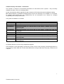
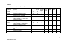
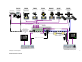
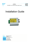
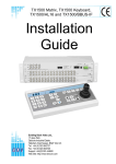
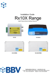
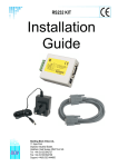
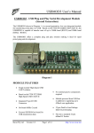
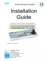
TX1000 Telemetry Transmitter
Installation
Guide
Model Shown: TX1000/16/A/DC
Building Block Video Ltd
17 Apex Park
Diplocks Industrial Estate
Hailsham, East Sussex, BN27 3JU, UK
Tel: + 44 (0) 1323 842727
Fax: + 44 (0) 1323 842728
Support: + 44 (0) 1323 444600
www.bbvcctv.com
Contents
Important – Before you install
3
TX1000 Telemetry Transmitter – an Introduction
4
Unpacking
5
A simple TX1000 system
6
Technical Specification
7
Layout of the TX1000 keypad
8
Installing the TX1000 matrix & keypad
8
Status LEDs
9
Siting the keypad remotely from the base unit
9
Cable Connections
9
Keypad power requirements
9
Priority control between 2 keypad systems
9
Text display on screen
9
Camera selection
10
Monitor selection
10
Activating the sequence
10
Programming the sequence
10
Setting the sequence delay
10 - 11
Triangle key
11
Keypad functions
12
Auxiliary function switches
12
Self test
13
Iris level program
13
Maximum camera number
14
Presets
14
Patrol settings
15 - 16
Spare outputs – control of special receiver functions
16
RS422 telemetry
17
TX1000 alarm input option
18 – 20
Appendix
Useful keystrokes
TX1000 Alarm program table
i
ii
2
TX1000 manual V7 June 09
IMPORTANT
Before you install:
Please read the following points before servicing or installing.
Pre-installation checks - It is recommended that the unit be bench tested prior to installation on the site.
Safety during installation or servicing - Particular care should be taken to isolate the pan/tilt head in order
to prevent operation while engineering work is being carried out. In addition any ladder or other means of
working on the receiver MUST NOT rest on the pan/tilt head as it is possible for the head to move when not
expected.
Safety check - Upon completion of any service or repairs to the unit, safety checks should be performed to
ensure that the unit is in proper operating condition.
Coax grounding - If an outside cable system is connected to the unit, be sure the cable system is
grounded.
Adhere to safety standards - All normal safety precautions as laid down by British Standards and the
Health and Safety at Work Act should be observed.
WARNING - TO PREVENT DANGER OF FIRE OR SHOCK, DO NOT EXPOSE THE INTERNAL
COMPONENTS OF THIS EQUIPMENT TO RAIN OR MOISTURE.
Damage requiring service - Servicing by qualified personnel should be carried out under the following
conditions:
(a) When the power supply cord or plug is damaged;
(b) If liquid has been spilled, or objects have fallen into the unit;
(c) If the unit does not operate normally by following the operating instructions;
(d) If the unit has been dropped or the enclosure is damaged
Replacement parts - If replacement parts are required, ensure that only replacement parts recommended
by the product manufacturer are used.
3
TX1000 manual V7 June 09
TX1000 Telemetry Transmitter – Introduction
The TX1000 is a simple to use telemetry transmitter for multi-camera CCTV systems. They are easily
installed into either a new or an existing system.
Up-the-coax telemetry allows upgrading of static cameras to PTZ without the need for additional cabling.
BBV RS422 telemetry is available as standard where up-the-coax telemetry is not suitable or not required.
An optional 20mA twisted pair unit (TX/MK2/TPO) can be retro-fitted to the TX1000 for complete
compatibility with existing TX1000 sites.
The system is available in 12 variants:
Part Number
TX1000/8
TX1000/8A
TX1000/8/DC
TX1000/8A/DC
TX1000/8/MU
TX1000/8A/MU
TX1000/16
TX1000/16A
TX1000/16/DC
TX1000/16A/DC
TX1000/16/MU
TX1000/16A/MU
Description
Telemetry transmitter for 8 cameras with 2 monitor outputs
Telemetry transmitter for 8 cameras with 2 monitor outputs, 16 alarm input card
Telemetry transmitter for 8 cameras with 2 monitor outputs, with joystick Keypad
Telemetry transmitter for 8 cameras with 2 monitor outputs, 16 alarm input card and
joystick Keypad
Telemetry transmitter for 8 cameras with 2 monitor outputs, no Keypad
Telemetry transmitter for 8 cameras with 2 monitor outputs, 16 alarm input card, and
no Keypad
Telemetry transmitter for 16 cameras with 2 monitor outputs
Telemetry transmitter for 16 cameras with 2 monitor outputs, 16 alarm input card
Telemetry transmitter for 16 cameras with 2 monitor outputs, with joystick Keypad
Telemetry transmitter for 16 cameras with 2 monitor outputs, 16 alarm input card and
joystick Keypad
Telemetry transmitter for 16 cameras with 2 monitor outputs, no Keypad
Telemetry transmitter for 16 cameras with 2 monitor outputs, 16 alarm input card,
and no Keypad
All variants allow the use of two fully independent keypads.
The transmitter is a two part design: the base unit, which is wall or rack mounting; and the keypad which is
connected by a video cable and a bi-directional RS232 link running at 9600 baud, No parity, 8 data bits and
1 stop bit.
4
TX1000 manual V7 June 09
Unpacking
Inspect the packaging for signs of damage. If damage has occurred, advise the carriers and/or the suppliers immediately. Unpack the transmitter carefully
and check all the items are included:
Part Number
TX1000/8
TX1000/8A
TX1000/8/DC
TX1000/8A/DC
TX1000/8/MU
TX1000/8A/MU
TX1000/16
TX1000/16A
TX1000/16/DC
TX1000/16A/DC
TX1000/16/MU
TX1000/16A/MU
Description
Telemetry transmitter for 8 cameras with 2
monitor outputs
Telemetry transmitter for 8 cameras with 2
monitor outputs, 16 alarm input card
Telemetry transmitter for 8 cameras with 2
monitor outputs, with joystick KBD
Telemetry transmitter for 8 cameras with 2
monitor outputs, 16 alarm input card and joystick
KBD
Telemetry transmitter for 8 cameras with 2
monitor outputs, no KBD
Telemetry transmitter for 8 cameras with 2
monitor outputs, 16 alarm input card, and no KBD
Telemetry transmitter for 16 cameras with 2
monitor outputs
Telemetry transmitter for 16 cameras with 2
monitor outputs, 16 alarm input card
Telemetry transmitter for 16 cameras with 2
monitor outputs, with joystick KBD
Telemetry transmitter for 16 cameras with 2
monitor outputs, 16 alarm input card and joystick
KBD
Telemetry transmitter for 16 cameras with 2
monitor outputs, no KBD
Telemetry transmitter for 16 cameras with 2
monitor outputs, 16 alarm input card, and no KBD
TX1000
main unit
Keypad
2x
mounting
brackets
4x
M4
screws
PSU
Manual
Warranty
card
X
X
X
X
X
X
X
X
X
X
X
X
X
X
X
X
X
X
X
X
X
X
X
X
X
X
X
X
X
X
X
X
X
X
X
X
X
X
X
X
X
X
X
X
X
X
X
X
X
X
X
X
X
X
X
X
X
X
X
X
X
X
X
X
X
X
X
X
X
X
X
X
X
X
X
X
X
X
X
X
5
TX1000 manual V7 June 09
static camera
RX100
RX200
RX200
RX300
RX400P
RX45X
RX55X
dome camera
4 local alarms
Static camera with
lights/wash/wipe
Simple AC panner
AC P/T Zoom/Focus
1 Aux
AC P/T Zoom/Focus
16 Presets with 4 Aux
AC P/T Zoom/Focus/Iris
32 Presets with 3 or 4 Aux
8 local alarms
DC P/T Zoom/Focus/Iris
32 Presets with 3 or 4 Aux
8 local alarms
STATIC
alarm cable
video & data
up-the-coax telemetry control up to 250m RG59 or 500m CT125
TX1000/8A
Alarm cable or
Security Enclosures'
Videswitch can be
used to transmit
alarm contact over
coax
Monitor 2 video out
RS422
TXLD
Monitor 1 video out
9V plug
PSU
Twin Twisted
Pair
TXLD
Optional TXLD (RS422) link
Distance > 1200m
RS232 control - up to 50m
9V plug
PSU
TX1000/DC/KBD Additional keyboard
A Simple TX1000 System
TX1000 manual V7 June 09
6
Technical Specification
Power supply
Inputs
Outputs
Features
Installation
Dimensions
TX1000/KBD
TX1000/KBD/DC
Base Units:
TX1000/8
TX1000/8A
TX1000/16
TX1000/16A
9V dc 500mA
Data input to base unit is RS232 via 9-pin D connector RS232 port allowing remote
control from PC (9600, N, 8, 1)
BBV up the coax
BBV RS422
20mA option (order the TX/MK2/TPO)
2 keypads supported
2 monitor outputs
8 – 16 camera inputs
Optional alarm input
Up-the-coax & RS422 telemetry supported
Can be powered off 12V vehicle supply
Base unit is 2U 19in rack mountable metalwork or wall mounted via the fixing
brackets supplied
Width
Depth
Height
Weight
427mm
45mm
180mm
3 kg
427mm
115mm
180mm
3 kg
427mm
427mm
427mm
427mm
55mm
55mm
55mm
55mm
90mm
90mm
90mm
90mm
4 kg
4 kg
4 kg
4 kg
7
TX1000 manual V7 June 09
Layout of the TX1000 keypad
9V ac/dc
Video in Video out
Installing the TX1000 Matrix & Keypad
1.
Mount the base unit on the wall or in a rack.
2. Connect the keypad to 9 pin D connector to the relevant keypad socket on the Matrix:
Monitor 1 – Keypad 1
Monitor 2 – Keypad 2
3. Connect a BNC cable from output M1 to the keypad, and connect the other keypad BNC to the video
monitor’s video input. Make sure that the monitor is terminated, not Hi-Z.
4. If the keypad is remotely sited from the base unit, connect the 9Vdc plug mounted power supply to the
keypad via the 2.1mm power connector.
5. Connect either a second video monitor, or the second keypad to Output 2. Note that even if both
keypads are local to the main unit, the second keypad must be powered from its own 9Vdc power
supply.
6. Connect the BNC cables from the cameras/receivers to the upper BNC sockets in each row, marked
"VIDEO IN".
7. Connect any other equipment requiring the camera video signals to the lower BNC sockets marked
"LOOP OUT". Note that the action of connecting to the video out socket removes the 75Ω termination.
8. If the user relay terminals are being used, connect these to the LOW VOLTAGE equipment of your
choice.
PIN 6
PIN 7
PIN 8
Normally closed
Common
Normally open
9. Plug in the Matrix 9Vdc power supply.
8
TX1000 manual V7 June 09
Status LED
The STATUS LED should flash and the monitors should show the video from Camera 1 on power up. If the
LED is permanently ON or OFF, the unit is in a fault condition. Please contact BBV technical support on:
01323 444600.
Siting the keypad remotely from the base unit
The keypad uses RS232 9600 baud, no parity, 1 stop bit to communicate with the TX1000 Matrix. The
keypad is full duplex will function normally up to 50m from the Matrix. Beyond this distance, any of the
proprietary cable extenders may be used (e.g. modems, fibre optics, infra red/microwave links) without any
difficulty.
Cable Connections
Tx1000 Main Unit
DB9-Female
Keyboard
DB9-Male
9V Supply
RS232 Data
RS232 Data
Signal Ground
1
2
6
3
7
4
8
5
5
9
4
9
3
8
2
7
1
6
Frame Ground
Frame Ground
Keypad power requirements
Fully isolated 9 – 12V ac/dc power supply. The maximum current draw is 150mA.
Priority control between two keypad systems
Keypad one has priority over keypad two. If keypad one is only viewing but not operating any camera, then
keypad two may move that same camera. After movement commands on keypad one, there is a 20 second
lock out period before control is given to keypad two.
Text display on screen
Monitor 1:
Connect a coax cable from the M1 output on the matrix to the keypad, and connect the keypad to the
monitor’s video output using the other BNC on the keypad.
Monitor 2:
With one keypad - Connect as above, then connect a coax link from Monitor 1 to Monitor 2. This duplicates
the text onto both screens.
With two keypads – Connect a coax cable from the M2 output on the matrix to the keypad, and connect the
keypad to the monitor’s video output using the other BNC on the keypad.
9
TX1000 manual V7 June 09
Camera Selection
A camera may be selected onto the controlled monitor by pressing the relevant numbered camera key:
1
2
3
4
5
6
7
8
9
10
11
12
13
14
15
16
Monitor Selection
The monitor key has a red LED, which is lit when the keypad is controlling the second monitor output.
MONITOR
Pressing the monitor key toggles between monitor 1 and monitor 2.
Activating the Sequence
Pressing the sequence key will start the camera sequence on the monitor that is currently selected.
SEQ
The on screen display changes from CAM XX to SEQ XX to indicate that the sequence is running. To stop
the sequence, select a camera on the monitor.
Programming the Sequence
Holding down the sequence key causes the sequence to run through the list of cameras at the rate of one
per second, allowing the operator to quickly determine which cameras are being sequenced. All cameras
are included by default.
To add/remove a camera from the Sequence, hold the Sequence key and press the relevant camera key.
This will add/remove the camera from the Sequence.
Setting the Sequence delay
Determine the delay you wish to set from the table below:
Key number
1
2
3
4
5
6
7
8
Time delay (seconds)
5
10
15
20
25
30
35
40
Key number
9
10
11
12
13
14
15
16
Time delay (seconds)
45
50
55
60
65
70
75
80
10
TX1000 manual V7 June 09
Press the Program key to enter the menu and select ‘9’. The on screen prompt "Seq Delay" appears,
inviting the operator to enter a number from the table above for the time delay.
PROGRAM
Menu
Option
9
And
?
Delay number
After entering the delay value, the screen clears.
Triangle key
This key activates a relay in the base unit:
Pressing the key causes triangle relay contacts to changeover; releasing the key causes the contacts to
revert to original position. This relay may be used by the installer to activate a panic record facility on a VCR,
or to activate a video printer, etc. These contacts are low voltage, low current only.
DO NOT CONNECT THESE CONTACTS TO MAINS POTENTIALS.
USE LOW VOLTAGE ONLY.
11
TX1000 manual V7 June 09
Keypad functions
The keypads should not be connected or disconnected from a "live" working unit, as this may damage the
RS232 components.
Pan and Tilt Action:
Press the relevant direction arrow
Lens Action
There are six lens function switches on the TX1000
keypad. These are:
Iris Open
Iris Close
Focus Near
Focus Far
Zoom In
Zoom Out
Press and hold the relevant key until the desired
picture is obtained.
Note: If the key is pressed and held for longer than one second, High Speed Lens Action is activated.
Inching is achieved by repeated quick presses of the key.
Auxiliary function switches
There are four auxiliary function switches on the TX1000 keypad:
Wash – Press and hold for washer motor to run
Wipe - Latching output, press on/press off
12
TX1000 manual V7 June 09
Autopan - Press, LED lights up and autopan motor starts. Pressing Left or Right stops Autopan
Lights - Latching output, press on/press off
Self Test
To activate the self test feature for any particular camera receiver, first select that receiver, then press the
‘Program’ button and select ‘Menu Option 2’.
The screen text will clear and Self Test will be activated. See the RX Series Telemetry Receiver Installation
Handbook for more details.
PROGRAM
And
option
2
Iris Level Program
To preset the aperture of the iris, press ‘Iris Open’ or ‘Iris Close’ until the desired level is reached, then press
‘Program’ and ‘Option 3’.
PROGRAM
And
option
3
Note: After adjustment, there is a 15 second period, in which to program the iris setting. After this, the iris
reverts to its default setting.
13
TX1000 manual V7 June 09
Maximum Camera Number
To set the Maximum camera number, Press Program, then enter 15 followed by the maximum number of
cameras connected to the system
PROGRAM
And
Option
15
?
Then
Maximum camera
number
Setting the maximum camera number will prevent the TX1000 from patrolling through unused cameras on a
patrol.
The remainder of this manual refers to features found only on receivers that
support presets: RX100, RX400P, RX45X, RX55X
Presets
To select a programmed preset, press the Preset key. On the screen, ‘Preset’ will appear. While holding
down the Preset key, press the required preset number.
Go To
Preset
PRESET
And
?
Preset number
To programme a preset, first position the camera using the Up/Down and Left/Right arrows. Then set Zoom
and Focus. When satisfied with the position and the quality of the picture, press Program and select Option
1. When the on screen display changes to "Program Preset", enter the number of the preset you wish to
program.
Program
Preset
PROGRAM
Menu
Option
1
Then
?
Preset number
To erase a preset, press the Program key to gain access to the menu. Select Option 4 and when the
display changes to "Erase Preset", select the number of the preset to be erased.
Erase
Preset
PROGRAM
Menu
Option
4
Then
?
Preset number
14
TX1000 manual V7 June 09
Patrol settings
There are two preset patrols that can be started by the TX1000.
To activate: Press and hold the Patrol key and either Key 1 or Key 2. All other keys are ignored. Their
function is to enable a string of presets to be selected in turn, switching between presets after a fixed period
of time (default 30 seconds).
These patrols can be stopped at any time by pressing any of the four arrows on the Pan and Tilt control or
moving the joystick, when the receiver on which patrol is running is selected.
To Programme a Patrol
There is no separate patrol-programming function with the BBV TX1000 keypad. Once a preset has been
programmed, it is automatically included in Patrols 1 and 2.
To Remove a Preset from a Patrol
1. Select the receiver on which the patrol is to run.
2. Press Program to gain access to the menu, then press 5 to remove a preset from Patrol 1 or 6 to
remove from Patrol 2, followed by the preset number to be removed.
To Remove a Preset from Patrol 1:
PROGRAM
Menu
Option
5
Then
?
Preset number
To Remove a Preset from Patrol 2:
PROGRAM
Menu
Option
6
Then
?
Preset number
To Programme a Time Period for a Patrol
First, determine the time delay required from the table below:
Key Number
1
2
3
4
5
6
7
8
Time delay (seconds)
Random 0 to 100 seconds
12
24
36
48
60
72
84
Key Number
9
10
11
12
13
14
15
16
Time delay (seconds)
96
108
120
132
144
156
168
180
15
TX1000 manual V7 June 09
Setting a delay for Patrol 1:
PROGRAM
Menu
Option
7
Then
?
Delay number
Setting a delay for Patrol 2:
PROGRAM
Menu
Option
8
Then
?
Delay number
Spare outputs – Control of special receiver functions
Four additional spare functions are provided which are used to carry out advanced programming depending
on the type of receiver and/or dome used. Please refer to the receiver’s manual for details.
The additional functions are activated by pressing the # key and one of the auxiliary keys simultaneously.
An on screen display confirms which output has been activated.
#
And
= #1
#
And
= #2
#
And
= #3
#
And
= #4
16
TX1000 manual V7 June 09
RS422 TELEMETRY
The TX1000 matrix has a single RJ45 connector that is used to control BBV RS422 telemetry receivers or a
range of 3rd party receivers and dome cameras via a STARCARD/CONVERTER. It is recommended that a
RJ45 breakout box and CAT5 patch cable are used to connect the telemetry connector.
RX45X/RX55X
RX45X/RX55X
RS422
connectors
RB
RA
GND
TRB
TRA
RB
RA
GND
TRB
TRA
RS422
connectors
RB
RA
GND
TRB
TRA
RS422
connectors
RX45X/RX55X
TxB to RB (-) = 5
4 = TxA to RA (+)
Do not use = 6
3 = Do not use
Do not use = 7
2 = Do not use
Screen = 8
1 = Do not use
RJ45 breakout box
TX1000/8A base unit
Cat 5 patch cable
When daisy chaining the RS422 telemetry ensure that the end of line receiver has RS422 terminated and
intermediate receivers are not terminated.
Terminated
Un - terminated
If the system is to be star wired then a BBV STARCARD can be used which provides 8 individual RS422
outputs.
A STARCARD/CONVERTER can be used to allow control of a range of 3rd party domes and telemetry
receivers with 8 x RS422 outputs.
17
TX1000 manual V7 June 09
TX1000 Series Alarm Input Option
Alarm Inputs
Alarms activate on opening of contacts. Connect each alarm pair to a volt free contact.
1
G
N
D
2
G
N
D
3
G
N
D
4
G
N
D
5
G
N
D
6
G
N
D
7
G
N
D
8
G
N
D
9
Normaly closed inputs, opening for alarm
G
N
D
1
0
G
N
D
1
1
G
N
D
1
2
G
N
D
1
3
G
N
D
1
4
G
N
D
1
5
G
N
D
1
6
Each input has 56K internal pull up to 9Vdc
Alarm output
1 2 3
Set - N/O
Common
Reset - N/C
A set of volt free changeover contacts are provided as an output from the alarm package. The contacts
change state when any alarm input has gone from closed to open. The contacts stay switched for a
programmed length of time. The contacts are accessed via contacts 3, 4 & 5 on the smaller green ‘RELAY
CONTACTS’ connector.
4 5
6 7
8
TIME LAP S E
* Linking pins 1 & 2 will disable the TX1000 alarm handling. Any receiver local alarms are not disabled.
DO NOT CONNECT MAINS POTENTIALS TO THESE CONTACTS
USE LOW VOLTAGE ONLY!!
18
TX1000 manual V7 June 09
G
N
D
Enabling/Disabling the Alarm package
The alarm package can be enabled/disabled; for example at night
when the building is empty the alarms can be enabled via a
keyswitch fitted across alarm contacts pins 1 and 2.
ALARM CONTACTS
Installer fitted keyswitch to
control alarm package
Closed switch = alarm package disabled
Open switch = alarm package active
Local alarms to the receiver will NOT be disabled using this link.
Keyswitch
Note: Cutting the switch cable will activate the alarm package.
Action on alarm
Each alarm can be programmed to switch monitor 1 to display a specific camera and go to a preset position
for that camera. An alarm message is displayed on the screen and the alarm output relay closes for a
programmed length of time.
If the sequence is running then the alarm time is added to the sequence time, and the sequence continues
to run after the alarm times out.
If the sequence is not running, the alarm message and selected camera remain on monitor 1 until a manual
camera selection.
The camera selected and the preset command issued is programmable via the keypad. Press the program
key and select ’11’:
PROGRAM
Menu
Option
11
The following message then appears on screen:
Program Alarm?
Enter the alarm number you wish to program. Then the following prompt appears:
Camera?
Enter the camera number you wish to use when the alarm is trigerred.
Preset?
Enter the number of the Preset you wish to go to when the alarm is trigerred.
19
TX1000 manual V7 June 09
The length of time the contacts close is also programmable. To program the length of time the contacts
close:
First determine the amount of time you wish the contacts to be closed:
Key number
1
2
3
4
5
6
7
8
Time (seconds)
5
10
15
20
25
30
35
40
Key number
9
10
11
12
13
14
15
16
Time (seconds)
45
50
55
60
65
70
75
80
Press the Program key to enter the menu and select ‘10’ followed by the key number relating to the amount
of time the contacts are to be closed for:
PROGRAM
Menu
Option
10
Then
?
Key number
relating to
time delay
To use the preset features you must have fitted a receiver that supports preset positioning; RX400P,
RX45X, RX55X and preset PTZ heads or RX100 and a suitable dome camera.
Receivers with local alarms.
The RX100 dome interface has 4 local alarm inputs and the RX45X and RX55X have 8 local alarm inputs.
All have a single normally closed relay output that opens momentarily when a local alarm is activated. This
output can be wired to an alarm input on the TX1000 or an alarm system.
A receiver local alarm will cause the relevant preset position to be automatically selected without the
intervention of a telemetry transmitter (see the receiver installation guide). If the transmitter also generates
a preset command, then the receiver’s preset will be overridden. To overcome this during alarm
programming use preset 16 which will prevent the TX1000 from sending a preset command for this
particular alarm input.
The standard preset receivers can be programmed to go to a preset position 1 - 15 during an alarm.
20
TX1000 manual V7 June 09
- Blank for your notes -
21
TX1000 manual V7 June 09
Appendix
Useful Keystrokes:
Software version
Hold hash and tap the 10 key to make the software version number, number of watchdogs and number of
resets appear on screen.
#
And tap
10
i
TX1000 manual V7 June 09
TX1000 Alarm Program Table
Site Name
Date
PROGRAM
11
INPUT NUMBER
CAMERA NUMBER
PRESET
PROGRAM
11
1 to 16
1 to 8 or 1 to 16
1 to 16
PROGRAM
11
1
PROGRAM
11
2
PROGRAM
11
3
PROGRAM
11
4
PROGRAM
11
5
PROGRAM
11
6
PROGRAM
11
7
PROGRAM
11
8
PROGRAM
11
9
PROGRAM
11
10
PROGRAM
11
11
PROGRAM
11
12
PROGRAM
11
13
PROGRAM
11
14
PROGRAM
11
15
PROGRAM
11
16
ii
TX1000 manual V7 June 09
Extend your BBV Warranty from 12 months to 3 years
As of the 1st September 2008 BBV have offered our
customers the opportunity to extend the standard 12
month warranty to 3 years.
You must register for the extended warranty within 12
months of the date of manufacture.
How to register for the 3 year warranty
Registering for the new, longer 3 year warranty term is
quick and easy.
Either:
Complete the warranty application card that comes in the
box with your BBV product, and return it FREEPOST to
BBV:
BBV 3 Year Warranty
If this card is returned with the serial number of the product and the Installation company
details BBV will extend the warranty period from 12 Months to 36 Months.
Number of Units,
Start Serial No.
Final Serial No.
Contact Name.
Company Name.
Phone Number.
Site Name.
Address 1.
Address 2.
Address 3.
Post Code.
e-mail address.
Do you read.
Please could you send me information
especially on:
Rx100s
Rx45x & Rx55x
FBM Video Matrices
Tx1500 Video Matrices
Starcard & Starcard Converters
BBV Quad
Pick A Point
I do not require any other further product information,
Please refer to WWW.BBVCCTV.COM for terms, conditions & exclusions
VAT Reg. No. 621758439 Registered in England No. 2852921 Registered office: 17 Apex Park Diplocks Way Hailsham East Sussex UK BN27 3JU
Or alternatively:
Register online at: www.bbvcctv.com
Simply enter your details on the ‘Warranty Cover’ page.
Building Block Video Ltd
Tel: + 44 (0) 1323 842727
Fax: + 44 (0) 1323 842728
Support: + 44 (0) 1323 444600
TX1000 manual
V7 June 09
www.bbvcctv.com