1
2. INSTALLATION
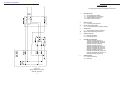
5. SCHEMATIC DIAGRAMS
2.3 Circuit Breaker Rating and Wire Gauge
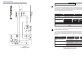
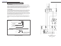
Systems with a Bypass Isolation Transformer Installed:
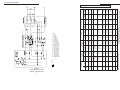
Install a Bypass Circuit Breaker with the current rating specified in Table 2. Use the
wire gauge, as specified, for all connections to the Bypass Switch, especially if there is
208V or 240V supplied to the load.
CAUTION: For UPS output configurations which supply both 120V and 208 / 240V loads,
care must be taken not to overload either of the output windings of the Bypass Transformer. The maximum current of each output winding is limited to the current rating at
208V (i.e., the maximum current rating for L1 or L2 is the VA rating of the transformer
divided by 208). Although CFR models up to 5000 VA are capable of supplying the full
rated power at 120V from L1, systems with a bypass transformer must have the 120V
loads split between L1 and L2. For CFR models 7.5K and greater the Bypass Transformer
rating is the same as the UPS output rating. Refer to the CFR Operator’s Manual for a
complete description on Load Sharing.
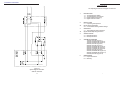
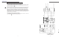
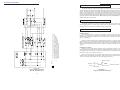
NOTES:
1.
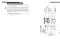
Terminal designatioons are shown for Standard BPT Series
Bypass transformers.
If BPT -S Series trandformers are used, refer to label on
transformer for actual terminal designations.
NOTE 1
Without Bypass Isolation Transformer Installed:
Install a Bypass Circuit Breaker with a current rating shown in Table 2. Use the wire
size specified for all connections to the Bypass Switch.
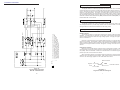
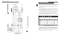
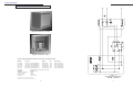
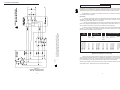
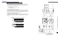
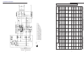
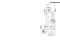
Figure 5.
System Bypass Schematic
208V IN - 120V OUT
6
15