1
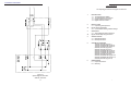
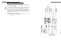
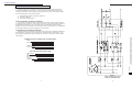
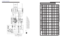
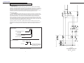
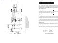
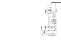
5. SCHEMATIC DIAGRAMS
3. OPERATION
3.1 Testing Bypass Switch Operation
CAUTION: This test must first be performed with all power to the Bypass Switch turned
OFF.
To test that all connections are made correctly, with all power to the bypass switch
turned off, measure the resistance between pin 2 & 3, 5 & 7, and between 9 & 11 to
ensure that there is no connection between the two sources of power (UPS and BYPASS). Then turn the switch to the BYPASS position and turn the UPS and the bypass
circuit breaker ON so that power from both sources is available at the bypass switch.
Verify the following voltages shown in the Table below.
Voltage Check:
Measuring Points
Ground to Neutral
Ground to L1
Ground to L2
(GND to pin 5/7 of BPS )
(GND to pin 1/3 of BPS )
(GND to pin 9/11 of BPS )
Phase Check:
L1, UPS - BYPASS
N, UPS - BYPASS
L2, UPS - BYPASS
Measured Voltages
Measuring Points
<5V
110 - 125 V
110 - 130 V if 240 V system
75 - 95 V if 208 V system
Make-BeforeBreak Bypass
Switch
(pin 2 to pin 4 of BPS)
(pin 6 to pin 8 of BPS)
(pin 10 to pin 12 of BPS)
< 20 V
< 20 V
< 20 V
Break-BeforeMake Bypass
Switch
< 100 V
< 20 V
< 100 V
Table 3.
BPS Voltages Phase Checks
DO NOT OPERATE THE SWITCH IF THE MEASURED VOLTAGES ARE GREATER
THAN SHOWN IN THE TABLE ABOVE.
If you cannot obtain the indicated voltages, check your wire connections. For example, is L1 of the UPS input connected to the same phase as L1 of the bypass line? Also
check the input and output voltages of the UPS and / or the Bypass Transformer as
shown in Table 4. Contact ALPHA if the phasing is not correct or if you need further
assistance.
UPS or BPT
Figure 4.
System Bypass Schematic
208V IN - 120V OUT
14
Measuring Points
Correct
Phasing
Out of Phase
CFR with 120 Volt input
input L1 to output L1
input L2 to output L1
< 30 V
> 180 V
> 180 V
< 30 V
CFR with 208 or 240 V input
input L1 to output L1
input L2 to output L1
< 100 V
> 180 V
> 180 V
< 100 V
Bypass Transformer
H1 to X1
H1 to X5
< 100 V
> 200 V
> 200 V
< 100 V
Table 4.
UPS / BPT Voltage and Phase Checks
(All measurements are at no load)
7