1
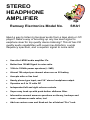
STEREO
HEADPHONE
AMPLIFIER
Ramsey Electronics Model No.
SHA1
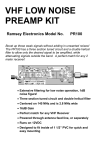
Need a way to listen to line level audio from a tape deck or CD
player? Need a way of boosting up any low level signal to
earphone level for top quality stereo listening? This kit has CD
quality audio capabilities with super low distortion, a wide
frequency spectrum, and a superior signal to noise ratio!
•
Uses the LM386 audio amplifier ICs.
•
Better than 100dB Signal to noise ratio.
•
10Hz to 100kHz power spectrum (+-3dB)
•
Almost 1W output per channel when run on 9V battery
•
Accepts mike or line level
•
Handy phono type input, and 1/4” stereo headphone output
•
Operates on 9 to 15 volts DC
•
Independent left and right volume controls
•
Super easy hook-up with push-button sibilance filter.
•
Informative manual answers questions on theory, hookups and
uses - enhances resale value, too!
•
Add our custom case and Knob set for a finished “Pro” look.
SHA1• 1
RAMSEY TRANSMITTER KITS
• FM100B Professional FM Stereo Transmitter
• FM25B Synthesized Stereo FM Transmitter
• MR6 Model Rocket Tracking Transmitter
• TV6 Television Transmitter
RAMSEY RECEIVER KITS
• FR1 FM Broadcast Receiver
• AR1 Aircraft Band Receiver
• SR2 Shortwave Receiver
• SC1 Shortwave Converter
RAMSEY HOBBY KITS
• SG7 Personal Speed Radar
• SS70A Speech Scrambler
• BS1 “Bullshooter” Digital Voice Storage Unit
• AVS10 Automatic Sequential Video Switcher
• WCT20 Cable Wizard Cable Tracer
• LC1 Inductance-Capacitance Meter
RAMSEY AMATEUR RADIO KITS
• DDF1 Doppler Direction Finder
• HR Series HF All Mode Receivers
• QRP Series HF CW Transmitters
• CW7 CW Keyer
• CPO3 Code Practice Oscillator
• QRP Power Amplifiers
RAMSEY MINI-KITS
Many other kits are available for hobby, school, Scouts and just plain FUN. New
kits are always under development. Write or call for our free Ramsey catalog.
STEREO HEADPHONE AMPLIFIER KIT INSTRUCTION MANUAL
Ramsey Electronics publication No. MSHA1 Revision 1.2
First printing: September 1995
COPYRIGHT 1995 by Ramsey Electronics, Inc. 590 Fishers Station Drive, Victor, New York
14564. All rights reserved. No portion of this publication may be copied or duplicated without the
written permission of Ramsey Electronics, Inc. Printed in the United States of America.
SHA1 • 2
Ramsey Publication No. MSHA1
Price $5.00
KIT ASSEMBLY
AND INSTRUCTION MANUAL FOR
STEREO HEADPHONE
AMPLIFIER KIT
How does it work ....................
Assembly Strategy .................
Parts List ................................
Parts Layout Diagram ............
Part Values Diagram ..............
Schematic ..............................
Assembly Steps .....................
Testing the SHA1 ...................
Troubleshooting .....................
4
6
7
8
9
10
12
16
17
RAMSEY ELECTRONICS, INC.
590 Fishers Station Drive
Victor, New York 14564
Phone (585) 924-4560
Fax (585) 924-4555
www.ramseykits.com
SHA1• 3
What is it and how does it work?
Let’s take a look at the schematic diagram, and we will follow
through from input to output to get a general idea how this kit
works, and why. We will look only at the left channel circuitry
starting at J1 since the right channel is identical to the left.
A line level audio signal is placed in J1. Line level means an audio
signal of around 1V peak to peak, and will give a reading of 0dB
on a VU meter. The audio passes through C1, a coupling
capacitor. This capacitor prevents DC from entering the circuit
from external components and interfering with audio quality. The
capacitor lets the audio pass through to R3, the left channel
volume control.
The volume control simply varies the incoming signals level that
goes into U1, the LM386. U1 is a fully integrated audio amplifier,
capable of driving low impedance loads. It requires very few
external components, runs very efficiently, and has great fidelity.
With the sibilance switch open, the audio passes directly into U1,
and the signal is amplified to drive a low impedance speaker like
those in your earphones.
With the sibilance switch closed, the capacitor C12 is switched
into circuit. This capacitor shunts some of the higher frequencies
to ground, but leaves the lower frequencies alone. C12 creates a
low pass filter when combined with R2, thereby reducing the level
of high frequencies that are amplified in U1. This is really handy if
you have a noisy weak station coming in, or the signal source is
really tinny sounding like from a poorly recorded CD.
R4 and C5 on the output side of the LM386 is for preventing
oscillations due to the inductive nature of a speaker coil being
driven by the LM386. This makes the load of the speaker look
more like a resistive one than inductive, which prevents
“motorboating” of the audio signal.
SHA1 • 4
C3 is another coupling capacitor, and it serves the same
purpose as C1 at the start of the circuit. This prevents the DC
portion of the signal on the output of U1 from being sent to the
earphones.
VR1, C15 and C16 supply the regulated DC voltage for the
circuit.
SHA1• 5
RAMSEY “LEARN-AS-YOU-BUILD” ASSEMBLY STRATEGY
Be sure to read through all of the steps, and check the boxes as
you go to be sure you didn't miss any important steps. Although
you may be in a hurry to see results, before you switch on the
power check all wiring and capacitors for proper orientation. Also
check the board for any possible solder shorts, and/or cold solder
joints. All of these mistakes could have detrimental effects on your
kit - not to mention your ego!
Kit building tips:
Use a good soldering technique - let your soldering iron tip gently
heat the traces to which you are soldering, heating both wires and
pads simultaneously. Apply the solder on the iron and the pad
when the pad is hot enough to melt the solder. The finished joint
should look like a drop of water on paper, somewhat soaked in.
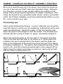
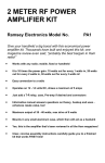
Mount all electrical parts on the top side of the board provided.
This is the side that has little or no traces on it. When parts are
installed, the part is placed flat to the board, and the leads are
bent on the backside of the board to prevent the part from falling
out before soldering (1). The part is then soldered securely to the
board (2-4), and the remaining lead length is then clipped off (5).
Notice how the solder joint looks on close up, clean and smooth
with no holes or sharp points (6).
SHA1 • 6
SHA1 PARTS LIST
Semiconductors
2 LM386 Audio Amplifier ICs (U1,2)
1 1N4002 rectifier diode (Black body with white stripe on
one end) (D1)
1 7808 Voltage Regulator (U3)
Resistors
2 4.7K ohm resistors (yellow-violet-red) (R2,7)
2 2 ohm resistors (red-black-gold) (R4,8)
2 10K ohm potentiometers (R3,6)
Capacitors
5 .01uF ceramic capacitors (Marked .01, 10n, or 103)
(C4,8,10,12,14)
4 10uF electrolytic capacitors (C1,6,15,16)
1 470uF to 1000uF capacitor (C2)
2 220uF capacitors (C3,7)
2 .1uF ceramic capacitors (Marked .1 or 104) (C5,9)
2 100pF ceramic capacitors (Marked 101) (C11,13)
Miscellaneous
2 DPDT switches (S1,2)
1 9V Metal Battery Holder
1 9V Battery Connector
1 1/4” Stereo earphone jack (J3)
2 RCA Jacks (J1,2)
1 Power Jack (J4)
SHA1• 7
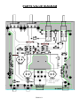
PARTS LAYOUT DIAGRAM
SHA1 • 8
PARTS VALUE DIAGRAM
SHA1• 9
SHA1 • 10
SHA1• 11
ASSEMBLING THE SHA1 HEADPHONE AMPLIFIERS:
Sort out all of your parts to begin with, making sure you have all
of the parts required. You can use old egg cartons to hold
various parts to make them easier to find. Make sure to mount
parts on the correct side! You will want to use the parts layout
diagram to assist you in finding where the parts go.
1. Orient the board in the same direction as the parts layout
diagram.
2. Install C12, a .01uF ceramic capacitor (Marked .01, 10n,
or 103)
3. Install C14, another .01uF ceramic capacitor (Marked .01,
10n, or 103).
4. Install R2, a 4.7K ohm resistor (yellow-violet-red).
5. Install R7, another 4.7K ohm resistor (yellow-violet-red).
6. Using a scrap piece of component lead, install JMP2.
These jumpers act as “bridges” over other connections,
allowing us to create a well routed PC board.
7. Using another scrap component lead, install JMP1.
8. Install C10, a .01uF ceramic capacitor (Marked .01, 10n,
or 103).
9. Install C8, another .01uF ceramic capacitor (Marked
10n, .01, or 103).
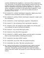
10. Install D1, the 1N4002 rectifier diode. Make sure and
install the lined end (cathode) of the diode in the same
direction as shown in the diagram. This diode prevents us
from accidentally charging an installed battery while external
power is applied.
SHA1 • 12
11. Install U2, one of the LM386 audio power amplifier ICs.
Check the orientation of this chip to make sure the dot or
notch representing pin one is in the same direction as shown
in the parts diagram. Make sure all eight pins are through
the board before soldering. Note that it is very easy to have
a pin folded under the IC instead of being though the holes.
This problem is easy to remedy before you solder the IC.
12. Install R8, a 2 ohm resistor (red-black-gold).
13. Install C9, one of the .1uF ceramic capacitors (Marked
104, or .1).
14. Install C13, a 100pF ceramic capacitor (Marked 101).
15 Using a scrap piece of component lead, install JMP5.
Note that this part does not need to be bent as shown in the
diagram, just make sure that it is installed in the correct
holes.
16. Install C4, a .01uF ceramic capacitor (Marked .01, 10n,
or 103).
17. Install R4, a 2 ohm resistor (red-black-gold).
18. Install U1, the remaining LM386 audio amplifier IC.
Again make sure that all eight pins are through the board
before soldering and that the part is installed in the correct
direction.
19. Install C11, a 100pF ceramic capacitor (Marked 101).
20. Install C5, a .1uF ceramic capacitor (Marked 104 or .1).
21. Install JMP4 using a scrap piece of component lead.
22. Install C2, a 470uF to 1000F electrolytic capacitor. Make
sure and mount this part in the correct direction! If you look
at the component you will see a stripe down one side,
SHA1• 13
usually indicating the negative (-) terminal of the component.
You will notice on the parts layout diagram that the hole for the
positive terminal is denoted, not the negative one. You will
want to install this component with the positive (+) lead in the
same orientation as shown in the parts layout diagram. If you
do not install it correctly, you will end up with all sorts of
problems in the circuit.
23. Install C3, a 220uF electrolytic capacitor. Again pay close
attention to the orientation of this component!
24. Install C7, another 220uF electrolytic capacitor. Again note
the orientation.
25. Install C6, a 10uF electrolytic capacitor. Orientation!
26. Install C1, the remaining 10uF electrolytic capacitor.
27. Install J3, the 1/4” earphone jack. Make sure all the pins
are soldered for good mechanical stability.
28. Install J1, one of the RCA type jacks.
29. Install J2, the other RCA type jack.
30. Install S1, a DPDT switch. Make sure the part is mounted
flush to the board before soldering all six pins.
31. Install S2, the other DPDT switch.
32. Install R3, one of the 10K ohm potentiometers.
33. Install R6, the other 10K ohm potentiometer.
34. Using a scrap piece of component lead, make a jumper
that mounts through the holes where the battery is to be
mounted. Thread the jumper through the metal 9V battery
holder and then solder the jumper to mount the clip to the PC
board.
SHA1 • 14
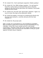
35. Install C16, 10uF electrolytic capacitor. Watch polarity!
36. Install U3, the 7808 voltage regulator. You will want to
bend the center lead out and orient the part so that the
writing on the front of the part faces the outside of the board.
Solder all three leads.
37. Install C15, the last 10uF electrolytic capacitor. Again, be
sure to orient the cap as the silkscreen shows.
38. Install the battery connector by soldering the black wire
into the hole marked (-), and the red wire into the hole
marked (+).
39. Install J4, the power jack.
Well, it looks as if we finished our new headphone amplifier!
Now would be a good time to check out your assembly for any
mistakes. Check all of your solder joints for cold solder
connections, and then check all of your traces and pads for any
solder bridges. Last of all check the orientation of all your parts
against the parts layout diagram.
SHA1• 15
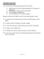
TESTING THE SHA1
You will need the following equipment for this test.
Audio source such as signal generator, CD player, or
tape deck.
RCA jacks to feed audio to the SHA1
Good quality headphones.
A 9 volt battery or DC power supply
Simply connect your SHA1 up as if you were going to use it.
1. Connect your signal source to the two RCA jacks on the
SHA1.
2. Hook up the 9V battery or power supply.
3. Turn the volume controls all the way counter clockwise.
4. Plug in your earphones.
5. Slowly turn up the volume slowly on each channel.
6. Use your ears and the troubleshooting guide to determine
if the unit works
SHA1 • 16
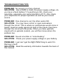
TROUBLESHOOTING TIPS
PROBLEM: No sound out of any channel.
SOLUTION: Use a DMM to check the power supply voltage, do
you have a fresh battery? If everything is OK, check your
assembly, especially your parts orientation (D1?). Also check
your earphones for proper operation as well as your sound
source.
PROBLEM: One channel is out, the other works OK.
SOLUTION: You may have a short or open somewhere
through the circuit. This is where an oscilloscope would come in
handy. Insert an audio signal into both of the inputs, then trace
through the circuit with the probe. When you have gazinda
(input) with no gazada (output), you will then know where the
problem lies.
PROBLEM: Sound is terrible or “motorboating”
SOLUTION: Check your power supply voltage or your battery.
PROBLEM: I just can’t get the #@%*$#&! thing to work! It’s
Ramsey’s fault!
SOLUTION: Read the warranty information towards the back of
this manual.
SHA1• 17
SHA1 • 18
The Ramsey Kit Warranty
Please read carefully BEFORE calling or writing in about your kit. Most problems can be solved
without contacting the factory.
Notice that this is not a "fine print" warranty. We want you to understand your rights and ours too! All
Ramsey kits will work if assembled properly. The very fact that your kit includes this new manual is
your assurance that a team of knowledgeable people have field-tested several "copies" of this kit
straight from the Ramsey Inventory. If you need help, please read through your manual carefully, all
information required to properly build and test your kit is contained within the pages!
1. DEFECTIVE PARTS: It's always easy to blame a part for a problem in your kit, Before you conclude
that a part may be bad, thoroughly check your work. Today's semiconductors and passive components
have reached incredibly high reliability levels, and it’s sad to say that our human construction skills
have not! But on rare occasions a sour component can slip through. All our kit parts carry the Ramsey
Electronics Warranty that they are free from defects for a full ninety (90) days from the date of
purchase. Defective parts will be replaced promptly at our expense. If you suspect any part to be
defective, please mail it to our factory for testing and replacement. Please send only the defective part
(s), not the entire kit. The part(s) MUST be returned to us in suitable condition for testing. Please be
aware that testing can usually determine if the part was truly defective or damaged by assembly or
usage. Don't be afraid of telling us that you 'blew-it', we're all human and in most cases, replacement
parts are very reasonably priced.
2. MISSING PARTS: Before assuming a part value is incorrect, check the parts listing carefully to see
if it is a critical value such as a specific coil or IC, or whether a RANGE of values is suitable (such as
"100 to 500 uF"). Often times, common sense will solve a mysterious missing part problem. If you're
missing five 10K ohm resistors and received five extra 1K resistors, you can pretty much be assured
that the '1K ohm' resistors are actually the 'missing' 10 K parts ("Hum-m-m, I guess the 'red' band
really does look orange!") Ramsey Electronics project kits are packed with pride in the USA. If you
believe we packed an incorrect part or omitted a part clearly indicated in your assembly manual as
supplied with the basic kit by Ramsey, please write or call us with information on the part you need
and proof of kit purchase
3. FACTORY REPAIR OF ASSEMBLED KITS:
To qualify for Ramsey Electronics factory repair, kits MUST:
1. NOT be assembled with acid core solder or flux.
2. NOT be modified in any manner.
3. BE returned in fully-assembled form, not partially assembled.
4. BE accompanied by the proper repair fee. No repair will be undertaken until we have received the
MINIMUM repair fee (1/2 hour labor) of $25.00, or authorization to charge it to your credit card
account.
5. INCLUDE a description of the problem and legible return address. DO NOT send a separate letter;
include all correspondence with the unit. Please do not include your own hardware such as
non-Ramsey cabinets, knobs, cables, external battery packs and the like. Ramsey
Electronics, Inc., reserves the right to refuse repair on ANY item in which we find excessive
problems or damage due to construction methods. To assist customers in such situations,
Ramsey Electronics, Inc., reserves the right to solve their needs on a case-by-case basis.
The repair is $50.00 per hour, regardless of the cost of the kit. Please understand that our technicians
are not volunteers and that set-up, testing, diagnosis, repair and repacking and paperwork can take
nearly an hour of paid employee time on even a simple kit. Of course, if we find that a part was
defective in manufacture, there will be no charge to repair your kit (But please realize that our
technicians know the difference between a defective part and parts burned out or damaged through
improper use or assembly).
4. REFUNDS: You are given ten (10) days to examine our products. If you are not satisfied, you may
return your unassembled kit with all the parts and instructions and proof of purchase to the factory for
a full refund. The return package should be packed securely. Insurance is recommended. Please do
not cause needless delays, read all information carefully.
SHA1• 19
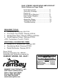
SHA1 STEREO HEADPHONE AMPLIFIER KIT
Quick Reference Page Guide
How does it work ..............................
Assembly Strategy............................
Parts List...........................................
Parts Layout Diagram .......................
Part Values Diagram ........................
Schematic .........................................
Assembly Steps ................................
Testing the SHA1 .............................
Troubleshooting ................................
4
6
7
8
9
10
12
16
17
REQUIRED TOOLS
• Soldering Iron Ramsey WLC100
• Thin Rosin Core Solder Ramsey RTS12
• Needle Nose Pliers Ramsey MPP4 or RTS05
• Small Diagonal Cutters Ramsey RTS04
<OR> Technician’s Tool Kit TK405
ADDITIONAL SUGGESTED ITEMS
Holder for PC Board/Parts Ramsey HH3
Desoldering Braid Ramsey RTS08
Digital Multimeter Ramsey M133
•
•
•
Price: $5.00
Ramsey Publication No. MSHA1
Assembly and Instruction manual for:
RAMSEY MODEL NO. SHA1
RAMSEY ELECTRONICS, INC.
590 Fishers Station Drive
Victor, New York 14564
Phone (585) 924-4560
Fax (585) 924-4555
www.ramseykits.com
SHA1 • 20
TOTAL SOLDER POINTS
about 100
ESTIMATED ASSEMBLY
TIME
Beginner ...............2.0 hrs
Intermediate .........1.0 hrs
Advanced ..............75 hrs