1
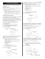
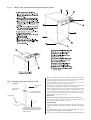
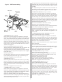
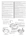
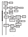
Extension flue lengths may be added horizontally and include a
second 90° flue bend providing the total straight length does not
exceed 2300 mm when measured from the side of the casing.
The flue system must be assembled from the Standard
Horizontal Side Flue Kit, extension flue kits and a second 90° flue
bend. See Fig. 12. 5.
The flue including the second 90° flue bend may be positioned
in any horizontal direction to suit the installation.
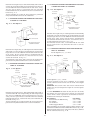
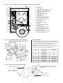
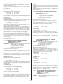
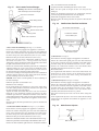
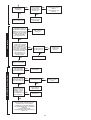
11.1.8 EXTENSION UPWARDS AND HORIZONTAL FLUE USING
A SECOND AND THIRD 90° FLUE BEND.
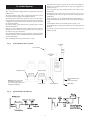
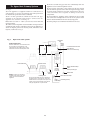
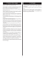
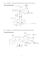
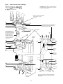
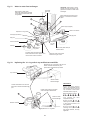
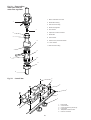
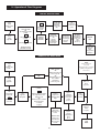
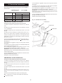
Fig. 12. 8.: Flue Option 8.
Third 90°
flue bend
Second 90°
flue bend
Straight
length
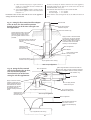
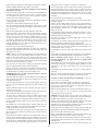
11.1.6 EXTENSION UPWARDS AND HORIZONTAL FLUE USING
A SECOND 90° FLUE BEND.
First 90°
flue bend
Fig. 12. 6.: Flue Option 6.
Straight
lengths
Appliance
Total straight flue length
1000mm maximum
Second 90°
flue bend
Straight
lengths
Extension flue lengths may be added upwards and horizontally
and include a second and third 90° flue bend providing the total
straight length does not exceed 1000 mm when measured from
the side of the casing. The flue system must be assembled from
the Standard Horizontal Side Flue Kit, extension flue kits, a
second and third 90° flue bend. See Fig. 12. 8.
The horizontal section of flue, second and third 90° flue bend
may be positioned in any horizontal direction to suit the
installation.
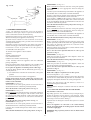
First 90° flue bend
Appliance
Total straight flue length
2300mm maximum
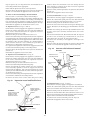
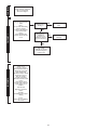
11.1.9 EXTENSION HORIZONTAL FLUE FITTED BEFORE THE
FIRST 90° FLUE BEND.
For Flue Options 2, 4, 5, 6, 7 and 8.
Extension flue lengths may be added upwards and horizontally
and include a second 90°flue bend providing the total straight
length does not exceed 2300 mm when measured from the side
of the casing. The flue system must be assembled from the
Standard Horizontal Side Flue Kit, extension flue kits and a
second 90° flue bend. See Fig. 12. 6.
The horizontal section of flue and second 90° flue bend may be
positioned in any horizontal direction to suit the installation.
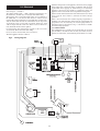
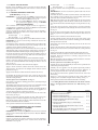
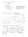
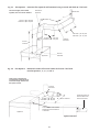
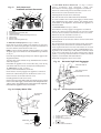
Fig. 12. 9.: Flue Option 9.
First 90°
flue bend
Appliance
side view
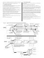
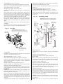
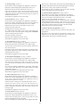
11.1.7 EXTENSION HORIZONTAL FLUE USING A SECOND AND
THIRD 90° FLUE BEND.
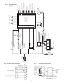
Fig. 12. 7.: Flue Option 7.
Appliance
First 90°
flue bend
Second 90°
flue bend
Third 90°
flue bend
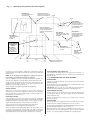
Note: A flue adaptor
must be fitted when a
horizontal section of flue
duct is required before
the first flue bend.
For Flue Options 2, 4, 5, 6, 7 and 8.
It may be required, because of site conditions, to fit a straight
section of flue duct before the first 90° flue bend. A flue adaptor
is required.
IMPORTANT: This section of flue duct must be included when
working out the total straight flue length for each Flue Option.
See Fig. 12. 9.
Appliance
Total straight flue length
1000mm maximum
Straight length must be
included when working
out the total straight flue
length
Straight
lengths
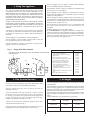
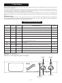
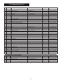
11.1.10 IMPORTANT: Extension flue kits,extra 90° flue bends,
flue adaptor, flue spacer and air duct supports are all optional
extras. All the extras required for the installation must be
available before starting the installation.
Optional Extra
Part Number
Extension Flue kit 1000 mm long
7 716 191 026
Flue Adaptor.
7 716 191 025
90° Flue Bend
7 716 191 013
Air Duct Support Bracket
7 716 191 024
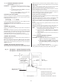
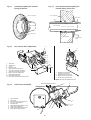
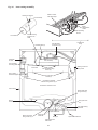
When determining the flue length required, always measure to the
outside of the wall where the flue terminal will be fixed. See Fig. 12.10.
When measuring between the centre lines of flue ducts, allow 83
mm for each flue bend. See Fig. 12.10.
Extension flue lengths may be added horizontally and include a
second and third 90° flue bend providing the total straight length
does not exceed 1000 mm when measured from the side of the
casing. The flue system must be assembled from the Standard
Horizontal Side Flue Kit, extension flue kits,second and third 90°
flue bends. See Fig. 12. 7.
The flue including the second and third 90° flue bends may be
positioned in any horizontal direction to suit the installation.
15