1
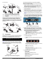
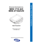
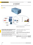
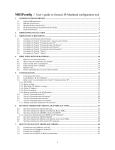
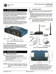
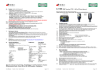
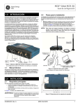
MDS TransNET
Publication No. 05-4481A01, Rev. A
1.0
INTRODUCTION
The transceiver, shown in Figure 1, is a spread spectrum radio
designed for license-free operation. These units employ Digital
Signal Processing (DSP) technology to provide highly-reliable
long-distance communications, even in the presence of weak
signals or interference.
The transceiver is housed in a compact and rugged die-cast
enclosure that need only be protected from direct exposure to the
weather. It contains a single printed circuit board with all necessary
components for radio operation. No jumper settings or manual
adjustments are required to configure the radio for operation.
In addition to these instructions, the MDS TransNET Reference
Manual (05-2708A01) provides helpful guidance on TransNET
systems. Electronic copies of all user documents and data sheets
are available free of charge at www.GEmds.com.
1.2
Typical Applications
1.2.1
Multiple Address Systems (MAS)
This is the most common application of the transceiver. It consists
of a central control station (Master) and two or more associated
Remote units, as shown in Figure 2. An MAS network provides
communications between a central host computer and remote
terminal units (RTUs) or other data collection devices. The
operation of the radio system is transparent to the computer
equipment. When used in this application, the transceiver provides
an excellent alternative to traditional (licensed) MAS radio
systems.
MDS TransNET
Remote
RTU
RXD
RTU
MDS TransNET
Remote
TXD
C
SYN
PWR
RXD
TXD
C
SYN
1.1
Transceiver Features
PWR
Listed below are several key features of the transceiver. These are
designed to ease the installation and configuration of the radio,
while retaining the ability to make changes in the future.
• 902–928 MHz operation using the TransNET 900
• 2400–2482 MHz ISM band operation with the TransNET
2400
• User-selectable option to skip sub-bands with constant
interference
• 65,000 available network addresses
• Network-wide configuration from the Master station eliminates most trips to Remote sites
• Data transparency ensures compatibility with virtually all
asynchronous SCADA system RTUs
• Peak-hold RSSI averaged over eight hop cycles
• Operation at up to 115,200 bps continuous data flow
• Store-and-Forward repeater operation
• Data latency typically less than 10 ms
• Same hardware for Master or Remote configuration
• Supports RS/EIA-232 and RS/EIA-485 user interface
• Low current consumption; typically less than 3 mA in “sleep”
mode
MDS TransNET
Remote
RXD
TXD
C
SYN
RTU
PWR
MDS TransNET
Master
RXD
RXD
TXD
TXD
C
SYN
C
SYN
PWR
RTU
PWR
MDS TransNET
Remote
Host System
Figure 2. Typical MAS Network
1.2.2
Point-to-Point System
A point-to-point configuration (Figure 3) is a simple arrangement
consisting of just two radios—a Master and a Remote. This
provides a half-duplex communications link for the transfer of data
between two locations.
Invisible
place
holder
MDS TransNET
Master
MDS TransNET
Remote
Host System
Figure 3. Typical Point-to-Point Link
1.2.3
Figure 1. MDS TransNET Series Transceiver
NOTE: Some radio features may not be available on all models,
or limited by the options purchased, or the applicable
regulatory constraints for the region in which the radio will
operate.
05-4481A01, Rev. A
Adding a Tail-End Link to an Existing
Network
A tail-end link can be used to extend the range of a traditional
(licensed) MAS system. This might be required if an outlying site is
blocked from the MAS Master station by a natural or man-made
obstruction. In this arrangement, a TransNET radio links the
outlying Remote site into the rest of a licensed MAS system by
sending data from that site to an associated TransNET installed at
one of the licensed Remote sites (see Figure 4 on Page 2).
As the data from the outlying site is received at the licensed
Remote site, it is transferred to the licensed radio (via a local cable
connection) and is then transmitted to the MAS Master station in
GE MDS TransNET Quick Start Guide
1
The following steps provide an overview of the installation
procedure. For additional details, refer to the MDS TransNET
Reference Manual (05-2708A01).
the usual manner.
REPEATER STATION
MDS x710B
Series Radio
Master Station
MDS TransNET
Master
1. Select a site that provides stable power, protection from the
weather, entrances for antenna and other cabling, and an
antenna location with an unobstructed transmission path in
the direction of the associated station(s).
SP
RE
TO AD
OU SPE
TL CT
YI RU
NG M
SI LIN
TE K
PWR
SYNC
TXD
RXD
ACTIVE
STBY
ALARM
RX ALR
TX ALR
ACTIVE
LINE
STBY
ALARM
RX ALR
TX ALR
LINE
ENTER
ESCAPE
Null-Modem Cable
2. Select and install an appropriate antenna and feedline for your
system requirements.
MDS TransNET
Remote
Remote
Radio
SYNC
TXD
RXD
OUTLYING
REMOTE SITE
RTU
RTU
RTU
3. Mount the transceiver to a stable surface using the brackets
supplied with the radio (fasteners/anchors are not supplied).
PWR
Remote
Radio
LICENSE-FREE SPREAD SPECTRUM SYSTEM
MAS SYSTEM (LICENSED OR UNLICENSED)
Figure 4. Typical Tail-End Link Arrangement
1.2.4
Extending a TransNET Network with a
Repeater
Similar to a Tail-End Link, Store-and-Forward (SAF) offers a way
to physically extend the network range, but in a simple and
economical manner. SAF works by dividing a network into a
vertical hierarchy of two or more sub-networks. Extension radios
(designated as MODE X) serve as single-radio repeaters that link
adjacent sub-networks, and move data from one sub-network to
the next one.
4. Connect the data equipment to the transceiver’s DATA connector. Use only the required pins for the application. Refer to
Figure 7.
5. Measure and install the primary power for the transceiver. It
must be within 6–30 Vdc (including transients) and be capable
of providing 7.5 watts over this voltage range. (Typical current
draw is 400 mA @13.8 Vdc; 0.9 A at 6 Vdc.) A power connector with screw-terminals is provided with each unit.
Invisible
place
holder
REPEATER STATION
SP
MDS TransNET
Master
MODE = M
SAF = ON
RE
TO AD
OU SPE
TL CT
YI RU
NG M
SI LIN
TE K
RTU
Antenna
Data
Primary Power
(6–30 Vdc)
Diagnostic (Payload)
(Communications)
MDS TransNET
Extension
MODE = X
MDS TransNET
Remote
MODE = R
Figure 7. Interface Connector Functions
MDS TransNET
Remote
MODE = R
RTU
MDS TransNET
Remote
MODE = R
OUTLYING
REMOTE SITE
RTU
RTU
Figure 5. TransNET Repeater Network
1.3
Accessories
7. Perform the initial start-up of the transceiver:
GE MDS offers an Accessories Selection Guide listing additional
items that may be used with our products. Contact your factory
representative or visit www.GEmds.com for the latest copy.
2.0
2.1
6. Set the radio’s basic configuration with a PC terminal connected to the DIAG(nostics) connector via an RJ-11 to DB-9
adapter cable, MDS P/N 03-3246A01. For more information
on connecting a PC terminal and preparing it for use, refer to
the MDS TransNET Reference Manual (05-2708A01).
Three essential settings for the transceiver are:
•
Mode: Master, Remote, or Extension
•
Network Address: A unique number from 1 to 65000
•
Data Interface Parameters: bps, data bits, parity, stop
bits
a.
Apply primary power.
b.
Observe the transceiver LED status panel for proper indications.
HARDWARE INSTALLATION
PWR
TransNET Installation
Figure 6 shows a typical Remote station arrangement. Master
stations are similar, but an omni-directional antenna is normally
used instead of a directional type, and a host computer replaces
the data terminal equipment.
DATA TERMINAL
EQUIPMENT
SYNC
TXD
RXD
In a normally operating system, you will see the following
indications within 16 seconds of start-up:
ANTENNA
SYSTEM
PWR lamp lit continuously
SYNC lamp lit continuously
Remote radio(s) transmitting data (TXD) and receiving
data (RXD) with the Master station.
MDS Transceiver
E
N
LI
D
SS
E
FE
O
POWER SUPPLY
13.8 VDC @ 500 mA
(6–30 Vdc)
-L
W
LO
Figure 6. Typical Remote Station Arrangement
2
8. Optimize the installation by checking:
• Antenna aiming
• Antenna SWR
• Data buffer setting (Modbus protocol)
• Hoptime setting
• TotalFlow™ Protocol at 9600 with Sleep Mode
• Operation at 115200 bps
• Baud rate setting
GE MDS TransNET Quick Start Guide
05-4481A01, Rev. A
• Radio interference checks
For more information on how to perform these optimization
steps, refer to the MDS TransNET Reference Manual
(05-2708A01).
3.0
RADIO PROGRAMMING
There are no manual adjustments on the radio. Programming and
control is performed through a PC connected to the radio’s DIAG
connector. Programming is performed by either establishing a
terminal connection to the radio (by using a terminal emulator such
as HyperTerminal), or by connecting to the radio using MDS
TransNET Configuration Software (P/N 06-4059A01). For more
information, refer to the MDS TransNET Reference Manual
(05-2708A01).
3.1
User Commands
The following tables provide brief descriptions of the various user
commands for the transceiver. For more information, refer to the
MDS TransNET Reference Manual (05-2708A01).
Table 3: Operational Configuration
COMMAND
DESCRIPTION
ADDR [1–65000]
Program network address
AMASK [0000
0000–FFFF FFFF]
Alarm response
ASENSE [HI/LO]
Sense of the alarm output on Pin 6 of the
DATA interface connector in the EIA-232
mode. Default: Alarm present = HI
BAND [A, B, C]
Selects one of three operating bands.
(2.4 GHz Model Only)
BAUD [xxxxx abc]
Data communication parameters
CODE [NONE, 1...255]
Select the security/encryption setting in
the radio
CSADDR [1–65000]
Used on a single Master/Remote network to support TDD-style simulated
full-duplex.
CTS [0–255]
CTS delay in milliseconds
(A value of 0 returns CTS immediately)
CTSHOLD [0–60000]
“Hold time” that CTS is present following
last character from DATA port.
DEVICE [DCE, CTS
KEY]
Device behavior:
DCE (normal) or CTS Key
MODE [M, R, X]
Operating mode:
M = Master, R = Remote, X = Extension
MRSSI [NONE,
-40...-90]
Minimum RSSI level required to preserve
synchronization with a Master radio for
Remotes in mobile service.
OT [ON, OFF]
Enables a 1-second delay on delivery of
RXD serial data.
OWN [xxxxx]
Owner’s name, or alternate message
(30 characters maximum)
PORT [RS232, RS485]
Data port (DATA connector) interface
signaling mode: RS232 or RS485
PWR [20–30]
Power output in dBm
RXD [0–255]
Set RXD delay time for virtual seamless
mode with low latency
RXTOT [NONE, 0–1440]
Maximum duration (in minutes) before
time-out alarm. Default is OFF.
RTU [ON, OFF, 0–80]
Enable or Disable unit’s built-in RTU
simulator. Default is OFF. Set RTU
address between zero and 80.
SLEEP [ON, OFF]
Enable or Disable the radio’s
energy-conservation Sleep mode function.
UNIT [10000–60000]
Unit address used for network-wide
diagnostics. (Unique within associated
network.)
XADDR [0–31]
This unit’s Extended address
Table 1: Network Configuration—Master Station
COMMAND
DESCRIPTION
AT [ON, OFF]
Enables Master station to emulate a
modem and respond to AT commands
BUFF [ON, OFF]
ON = Seamless data
OFF = Fast byte throughput.
FEC [ON, OFF]
Sets/disables FEC
(Forward Error Correction) setting.
HOPTIME [7, 28]
Displays hop-time or sets it to 7 or
28 ms.
LPM [1, 0]
Used at Master to set all associated stations in an energy-conservation mode.
1 = Low-power mode enabled network-wide
0 = Disable low-power mode (Default)
REPEAT
Sets/displays the fixed downstream
re-send count.
RETRY [0–10]
Sets/displays the maximum upstream
re-send count for ARQ (Automatic
Repeat Request) operation
SAF [ON, OFF]
SKIP [NONE, 1...8]
Enables/disables the store-and-forward
function for the network controlled by
this Master unit.
Skip one or more frequency zones
Table 2: Network-Wide Diagnostics
COMMAND
DESCRIPTION
DLINK [xxxxx/ON/OFF]
Controls operation of diagnostic link
function.
DTYPE [NODE/ROOT]
Set radio’s operational characteristics
for network-wide diagnostics
Default: FFFF FFFF
Typically, the Master is set to zero (0).
05-4481A01, Rev. A
XMAP
[00000000–FFFFFFFF]
Included Extended units in MODE X.
(Extensions and Remotes only)
XPRI [0–31]
Address of the primary Extended radio
unit (Extension).
GE MDS TransNET Quick Start Guide
3
Table 3: Operational Configuration (Continued)
COMMAND
DESCRIPTION
COMMAND
DESCRIPTION
XRSSI [NONE,
-40...-120]
Minimum RSSI level required to preserve
synchronization with a non-primary radio.
(Only meaningful when XPRI is not
NONE)
SAF
Store-and-forward mode status in this
unit. (ON/OFF)
SER
Serial number of radio
SHOW CON
Display virtual modem connection status
SHOW PWR
RF output power.
Measured RF power in dBm.
ZONE CLEAR
Reset zone data statistics
Table 4: Operating Status—Display Only
COMMAND
DESCRIPTION
SHOW SYNC
Information on synchronization source
ADDR
Network address
SKIP
Frequency zones that are skipped
AMASK
Alarm mask (response)
SLEEP
ASENSE
Current sense of the alarm output.
Radio’s Sleep Mode setting.
(At Remotes Only)
BAUD
Data communication parameters. Example: BAUD 9600 8N1
SREV
Transceiver firmware revision level
STAT
Current alarm status
TEMP
Transceiver’s internal temperature (°C)
UNIT
Programmed unit address for
network-wide diagnostics
“NONE” (Inactive), or “ACTIVE”
XADDR
This unit’s Extended address
CTS
CTS delay in milliseconds (0–255 ms)
XPRI
CTSHOLD
“Hold time” that CTS is present following
last character from DATA port.
Address of the primary Extended radio
unit (Extension).
XMAP
DEVICE
Device behavior
Included Extended units in MODE X.
(Extensions and Remotes only).
XRSSI
Minimum RSSI level required to preserve
synchronization with a non-primary radio.
(Only meaningful when XPRI is not
NONE)
BUFF
Data buffering mode: ON = seamless
data, OFF = fast byte throughput
CODE
Security/encryption operational status.
Alternatives: DCE and CTS KEY
HOPTIME
Hop-time value in milliseconds (ms).
LPMHOLD
Time (0-1000 ms) provided to give an
RTU time to respond before the radio
goes to sleep.
MODE
MRSSI
4
Table 4: Operating Status—Display Only (Continued)
Table 5: Diagnostic and Test Functions
Current operating mode:
COMMAND
DESCRIPTION
M = Master
R = Remote
X = Extension (Repeater)
KEY
Enables the transmitter test.
(must be in Setup mode).
DKEY
Turns off the transmitter test
(must be in Setup mode).
TX [xxxx]
Set/display transmit test frequency
(must be in Setup mode).
RX [xxxx]
Set/display receive test frequency.
(must be in Setup mode).
SETUP
Enables Setup mode.
Times out after 10 minutes. Press “Q” to
quit.
Minimum RSSI level required to preserve
synchronization with a Master radio for
Remotes in mobile service.
OWM
Owner’s message or site name
OT
Status (ON/OFF) of the 1-second delay
on delivery of RXD serial data.
OWN
Owner’s name or system name
PORT
Current data port (DATA connector) interface signaling mode: RS232 or RS485
ZONE DATA
Zone data statistics
PWR
Forward power-output setting in dBm
ZONE CLEAR
Clears the Zone Data log
REPEAT
The fixed downstream re-send count.
RETRY
The maximum upstream re-send count
for ARQ (Automatic Repeat Request)
operation.
RSSI
Received signal strength indicator (in
dBm). Unavailable at Master unless
SETUP is enabled.
RTU
RTU simulator’s operational status
(ON/OFF)
RXTOT
The amount of time (in seconds) to wait
before issuing a time-out alarm.
GE MDS TransNET Quick Start Guide
05-4481A01, Rev. A
4.0
If more than one alarm exists, the word MORE appears at the
bottom of the screen; additional alarms can be viewed by pressing
ENTER.
TROUBLESHOOTING
Successful troubleshooting of an MDS transceiver system is not
difficult, but requires a logical approach. It is best to begin
troubleshooting at the Master station, as the rest of the system
depends on the Master for polling instructions and synchronization
data. If the Master station has problems, the operation of the entire
network will be affected.
When communication problems are found, it is good practice to
begin by checking the basics. All radios in the network must meet
these basic requirements:
• Adequate and stable primary power
• An efficient and properly aligned antenna system
• Secure connections (RF, data & power)
• Proper programming of the radio’s operating parameters,
especially Operating Mode (MODE), Network Address
(ADDR), and interface Baud Rate (BAUD). For TransNET
2400 check the sub-band (BAND).
• The correct interface between the radio and the connected
data equipment (proper cable wiring, data format and timing).
• In store-and-forward systems there are several areas that
should be checked or evaluated:
• Look for duplicate XADDR values on MODE M and MODE X
radios. Duplicates will cause failures unless the radios are too
far apart to hear each other.
• Check for errors in the synchronization qualifiers, XPRI and
XMAP, on corresponding Remote radios.
• Verify SAF is enabled at the Master radio.
4.1
LEDs
Table 6 describes how to use the LEDs as a troubleshooting aid
whenever you suspect a problem with the transceiver.
Table 7: Alarm Codes
Alarm
Code
Alarm
Type
Description
00
Major
The network address is not programmed.
01
Major
Improper firmware detected for this radio model.
04
Major
One or more of the programmable synthesizer
loops is reporting an out-of-lock condition.
08
Major
The system is reporting that it has not been calibrated. Factory calibration is required for proper radio
operation.
10
Major
The DSP was unable to properly program the system to the appropriate defaults. A hardware problem may exist.
12
Major
Receiver time-out alarm.
16
Minor
The unit address is not programmed.
17
Minor
A data parity fault has been detected on the DATA
connector. This usually indicates a parity setting
mismatch between the radio and the RTU.
18
Minor
A data framing error has been detected on the
DATA connector. This may indicate a baud rate mismatch between the radio and the RTU.
29
Minor
RF output power fault detected. (Power differs by
more than 2 dB from set level.) Often caused by
high antenna system SWR. Check antenna, feedline and connectors.
30
Minor
The system is reporting an RSSI reading below
–105 dBm.
31
Minor
The transceiver’s internal temperature is approaching an out-of-tolerance condition. If the temperature
drifts outside of the recommended operating range
and the transceiver may fail.
Table 6: LED Indicator Descriptions
Name
Description
4.2.2
PWR
• Continuous—Power is applied to the radio; no problems detected
Major alarms report serious conditions that generally indicate a
hardware failure, or other abnormal condition that will prevent (or
seriously hamper) further operation of the transceiver.
With the exception of alarm code 00 (network address not
programmed), major alarms generally indicate the need for factory
repair. Contact MDS for further assistance.
Minor alarms report conditions which, under most circumstances,
will not prevent transceiver operation. This includes
out-of-tolerance conditions, baud rate mismatches, etc. The cause
of these alarms should be investigated and corrected to prevent
system failure.
• Flashing (5 times-per-second)—Fault indication. See
Section 4.0, Troubleshooting.
• Off—Radio is unpowered or in Sleep mode
SYNC
Continuous—Radio is receiving/sending synchronization
frames
On within 10 seconds of power-up under normal conditions
TXD
Transmit data activity on the DB-9 DATA interface connector
RXD
Receive data activity on the DB-9 DATA interface connector
4.2
Major Alarms versus Minor Alarms
Alarm Codes
When an alarm condition exists, the transceiver creates an alarm
code. These codes can be very helpful in resolving many system
difficulties.
4.2.1
Checking for Alarms—STAT command
To check for the presence of alarms, enter STAT. If no alarms
exist, the message NO ALARMS PRESENT appears at the top of
the display.
If an alarm does exist, a two-digit alarm code (00–31) is displayed,
and it is identified as a major or minor alarm. A brief description of
the alarm is also given. Alarm codes and their meanings are listed
in Table 7.
05-4481A01, Rev. A
GE MDS TransNET Quick Start Guide
5
4.3
Troubleshooting Chart
Table 8 provides suggestions for resolving system difficulties that
may be experienced in the radio system. If problems persist,
contact the factory for further assistance.
Table 8: Troubleshooting Guide
Difficulty
Recommended System Checks
Unit is
inoperative
a.Check for the proper supply voltage at the power
connector.
b.The transceiver’s internal fuse may have opened.
Interference is
suspected
a.Verify that the system has a unique network address. Nearby systems with the same address
will cause interference.
b.Check for interference by locking out affected
zone(s) using the SKIP command.
c. If omnidirectional antennas are used on Remote
stations, consider changing to directional antennas. This will often limit interference to and from
other stations.
No synchronization with Master,
or poor overall
performance
a.Check for secure interface connections at the radio and the connected device.
b.Check the antenna, feedline and connectors. Reflected power should be less than 10% of the forward power reading (SWR ≈ 2:1 or lower).
c. If the Remote radio is in synchronization, but performance is poor, check the received signal
strength using the RSSI command. If RSSI is
low, it may indicate antenna problems, or misalignment of directional antenna headings.
4.4
Technical Assistance
Factory technical assistance is available by contacting GE MDS
during business hours (8:30 AM to 6:00 PM Eastern Time). Use
one of the following means to contact the factory:
Telephone: (585) 241-5510
E-mail: [email protected]
Web: www.GEmds.com
FAX: (585) 242-8369
Part 15 Notice
This Equipment has been tested and found to comply with the
limits for a Class A digital device, pursuant to Part 15 of the FCC
Rules. These limits are designed to provide reasonable protection
against harmful interference when the equipment is operated in a
commercial environment. This equipment generates, uses, and
can radiate radio frequency energy and, if not installed and used in
accordance with the instruction manual, may cause harmful
interference to radio communications. Operation of this equipment
in a residential area is likely to cause harmful interference in which
case users will be required to correct the interference at their own
expense.
This device complies with Part 15 of the FCC Rules. Operation is
subject to the following two conditions: (1) this device may not
cause harmful interference, and (2) this device must accept any
interference received; including interference that may cause
undesired operation.
Warning: Changes or modifications not expressly approved by the
manufacturer could void the user’s authority to operate the
equipment.
d.Verify proper programming of system parameters: mode, network address, data interface baud
rate, transmitter power, CTS delay, etc. For
store-and-forward applications, also verify the
following: SAF is ON; extended address is properly programmed at each extension; Remotes
are using the proper values for XPRI and XMAP.
e.Check for alarms using the STAT command.
BER is too high.
Data throughput
is spotty
a.The RETRY and REPEAT commands may be increased to deal with interference, or decreased
to increase throughput and reduce latency.
b.Try turning on FEC. FEC on gives some coding
gain, but comes at the cost of reduced throughput.
Latency is too
high
a.Reduce the REPEAT count.
b.Turn BUFF OFF. BUFF ON ensures that no gaps
occur in the data, but this comes at the cost of increased latency.
c. Make sure HOPTIME is set to 7.
MDS TransNET Quick Start Guide
05-4481A01, Rev. A
July 2009
GE MDS, LLC
175 Science Parkway
Rochester, NY 14620
General Business: +1 585 242-9600
FAX: +1 585 242-9620
Web: www.GEmds.com