1
Department of Electrical Engineering and Information Technology
Institute for Media Technology
Distributed Multimodal Information Processing Group
Prof. Dr.-Ing. Eckehard Steinbach
Simulating and Deploying Home Automation
Components in Intelligent Environments
Simulation und Einsatz von Heim Automatiserungskomponenten in Intelligenten Umgebungen
Philip Parsch
Diploma Thesis
Author:
Philip Parsch
Address:
Matriculation Number:
Professor:
Prof. Dr.-Ing. Eckehard Steinbach
Advisor:
Dipl.-Ing. Luis Roalter
Prof. Dr. Matthias Kranz
Begin:
05.10.2012
End:
01.03.2013
Department of Electrical Engineering and Information Technology
Institute for Media Technology
Distributed Multimodal Information Processing Group
Prof. Dr.-Ing. Eckehard Steinbach
Declaration
I declare under penalty of perjury that I wrote this Diploma Thesis entitled
Simulating and Deploying Home Automation Components in Intelligent Environments
Simulation und Einsatz von Heim Automatiserungskomponenten in Intelligenten Umgebungen
by myself and that I used no other than the specified sources and tools.
Munich, March 1, 2013
Philip Parsch
Philip Parsch
Kurzfassung
In der Kurzfassung der Arbeit werden auf maximal einer Seite die Hintergründe, Motivation,
Aufgabenstellung und Lösungsansätze und die die Ergebnisse zusammengefasst.
Die Kurzfassung ist, sowohl auf Deutsch als auch auf Englisch, Bestandteil jeder Arbeit.
iv
Abstract
In the abstract, on a maximum of one page, the background, motivation, problem defition and
pursued solution strategy are summarized.
The abstract is in every thesis, in both English and German.
v
Contents
Contents
vi
1. Introduction
1
1.1. Motivation, Goals and possible Challenges . . . . . . . . . . . . . . . . . . . . .
1
1.2. Outline . . . . . . . . . . . . . . . . . . . . . . . . . . . . . . . . . . . . . . . .
2
2. Related Work/Fundamentals
3
2.1. Intelligent Environments . . . . . . . . . . . . . . . . . . . . . . . . . . . . . . .
3
2.2. Home Automation . . . . . . . . . . . . . . . . . . . . . . . . . . . . . . . . . .
4
2.2.1. Possibilities . . . . . . . . . . . . . . . . . . . . . . . . . . . . . . . . .
4
2.2.2. Structure . . . . . . . . . . . . . . . . . . . . . . . . . . . . . . . . . . .
6
2.2.3. Transmission media . . . . . . . . . . . . . . . . . . . . . . . . . . . . .
7
2.2.4. Example Systems . . . . . . . . . . . . . . . . . . . . . . . . . . . . . .
8
2.3. Home Automation Gateways . . . . . . . . . . . . . . . . . . . . . . . . . . . .
19
2.3.1. Example Gateways
. . . . . . . . . . . . . . . . . . . . . . . . . . . . .
19
2.3.2. Comparison . . . . . . . . . . . . . . . . . . . . . . . . . . . . . . . . .
21
2.4. Middleware . . . . . . . . . . . . . . . . . . . . . . . . . . . . . . . . . . . . . .
22
2.4.1. Example Middleware . . . . . . . . . . . . . . . . . . . . . . . . . . . .
22
2.4.2. Robot Operating System (ROS) . . . . . . . . . . . . . . . . . . . . . .
23
3. Concept
27
3.1. Basic structure . . . . . . . . . . . . . . . . . . . . . . . . . . . . . . . . . . . .
27
3.2. Hardware . . . . . . . . . . . . . . . . . . . . . . . . . . . . . . . . . . . . . . .
29
3.3. Software . . . . . . . . . . . . . . . . . . . . . . . . . . . . . . . . . . . . . . .
29
3.4. Device Management and Abstraction . . . . . . . . . . . . . . . . . . . . . . . .
30
3.5. Requirement Analysis . . . . . . . . . . . . . . . . . . . . . . . . . . . . . . . .
33
4. Implementation
36
4.1. Gateway . . . . . . . . . . . . . . . . . . . . . . . . . . . . . . . . . . . . . . .
36
4.1.1. Brief technical introduction of WifiControl 433 . . . . . . . . . . . . . .
36
4.1.2. Motivation . . . . . . . . . . . . . . . . . . . . . . . . . . . . . . . . . .
38
4.1.3. USB-serial-bridge Replacement . . . . . . . . . . . . . . . . . . . . . . .
40
vi
CONTENTS
4.1.4. Ceramic antenna for WLAN
vii
. . . . . . . . . . . . . . . . . . . . . . . .
41
4.1.5. Reprogramming of the RFM22B radio module . . . . . . . . . . . . . . .
41
4.1.6. Minor changes . . . . . . . . . . . . . . . . . . . . . . . . . . . . . . . .
45
4.1.7. Conclusion . . . . . . . . . . . . . . . . . . . . . . . . . . . . . . . . . .
46
4.2. Software Basics . . . . . . . . . . . . . . . . . . . . . . . . . . . . . . . . . . .
47
4.3. Gateway driver . . . . . . . . . . . . . . . . . . . . . . . . . . . . . . . . . . . .
47
4.4. Device manager . . . . . . . . . . . . . . . . . . . . . . . . . . . . . . . . . . .
50
4.4.1. Device manager class . . . . . . . . . . . . . . . . . . . . . . . . . . . .
53
4.5. Visualization . . . . . . . . . . . . . . . . . . . . . . . . . . . . . . . . . . . . .
55
4.5.1. The MainWindow class . . . . . . . . . . . . . . . . . . . . . . . . . . .
58
4.5.2. Visualization Menu . . . . . . . . . . . . . . . . . . . . . . . . . . . . .
60
4.5.3. Scene Menu . . . . . . . . . . . . . . . . . . . . . . . . . . . . . . . . .
62
5. Evaluation
65
5.1. Benchmarking . . . . . . . . . . . . . . . . . . . . . . . . . . . . . . . . . . . .
65
5.2. Home and office scenario . . . . . . . . . . . . . . . . . . . . . . . . . . . . . .
67
6. Conclusion
70
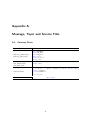
A. Message, Topic and Service Files
71
A.1. Gateway Driver . . . . . . . . . . . . . . . . . . . . . . . . . . . . . . . . . . .
71
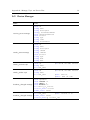
A.2. Device Manager . . . . . . . . . . . . . . . . . . . . . . . . . . . . . . . . . . .
72
A.3. Visualization . . . . . . . . . . . . . . . . . . . . . . . . . . . . . . . . . . . . .
75
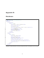
B. Databases
76
List of Figures
80
List of Tables
84
List of Acronyms
85
Bibliography
86
Chapter 1.
Introduction
New technologies provide increased comfort and quality in all areas of our lives. With home
and building automation, simple things like automatically raising the shutters in the morning as
well as more complex environments can be created. Particularly noteworthy is Ambient Assisted
Living (AAL), which enables the elderly and disadvantaged people to live independently. Many
studies have shown that being able to continue living at home with assistive technology, is in
most cases cheaper, more effective and more beneficial for the individual, than living in a care
or nursing home [1]. In addition, the rapid development of technologies in the field of computer
and communication has led to the development of smaller, more powerful and less expensive
devices. These devices will become more widespread and the interface man - technology will
become increasingly blurred. Weiser predicted this in 1991 [2] and called this type of computing
"Umbiquitous Computing". Umbiquitous Computing means that technology becomes absorbed
into everyday objects, enabling the user to use the system without explicitly being aware of it.
Unfortunately, in most home and building automation systems this development has been slow
due to a lack of standard communication interfaces.
1.1. Motivation, Goals and possible Challenges
This work provides a unified framework of Home Automation (HA) and Intelligent Environments
(IE), so that both systems can connect and benefit from each other. There are many advantages
for using HA components in IE:
Low-cost: Simple HA systems are usually produced in large quantities and are therefore usually cheaper than dedicated hardware, commonly used in IE. Consequently, there is a cost
advantage, when using HA for simple tasks such as switching electrical appliances on or off.
Intelligence: In contrast to HA, an IE can learn from user and environmental inputs, enabling
integration of HA in more complex systems.
1
Chapter 1. Introduction
2
Reuse: Already existing HA devices can be combined and reused. This reduces the installation
time as well as overall costs.
This work presents the integration of two exemplary HA systems, HomeEasy and Intertechno,
to an IE that uses middleware ROS. The implemented software consists of three parts: a driver
which programmatically abstracts the hardware to the middleware, a database container for storage
and mapping, and a graphical visualization program which provides a namespace service. As a
result, HA systems can be controlled via easily understandable ROS interfaces without the need
of detailed knowledge of communication parameters, such as protocol timings, package handling
and address mapping. The result of this work has been tested in an office and home scenario and
evaluated by various benchmarks.
The challenge faced in this project was to adapt the software to the special characteristics of
each supported HA system in order to allow as many systems as possible to be contolled without
compromising special functions. Since these systems may differ generally, difficulties may arise
when developing a storage class and functions for interconnection.
1.2. Outline
Chapter 2 covers the basics for all software and hardware parts of this work and presents other
projects with similar goals to provide an overview of current research projects.
Chapter 3 deals with the concepts and ideas of the process of integrating HA in IE. The software
and hardware used are presented and the abstraction chain and storage class are discussed in more
detail. Finally, a requirement analysis outlines the demands for the following software layers.
Chapter 4 deals with the implementation of the concepts as presented in the chapter 3. It consists
of two parts: Firstly, the used gateway and the changes that were undertaken to adapt it to this
work are introduced. Secondly, the different software parts and their interactions are examined.
Chapter 5 deals with the evaluation of the complete system. Two test scenarios are described,
one office and one home environment as well as various simulations for testing the performance
of the system.
Chapter 6 summarises this paper.
Chapter 2.
Related Work/Fundamentals
2.1. Intelligent Environments
Intelligent Environments (IE) are highly embedded, interactive spaces that aim to bring computation in to the real physical world [3]. They enhance the experience of everyday activities by
integrating heterogeneously distributed sensor-actuator systems into the environment and provide ambient services. They attempt to hide the complexity of the system and enable natural
interaction with it, such as voice, gesture, movement and context. The demands on these environments are high, as they change constantly and nomadic devices, such as smartphones enable
interaction for the user all over the space. To meet these requirements, IE need to be adaptable,
self-organizing and provide autonomous reasoning, which is more than simply connecting different
technologies [4].
One example of an IE is iDorm, as presented by Hagras et al. [5]. iDorm is a student’s dormitory, equipped with several sensors and actuators as well as a mobile service robot. It utilizes
autonomous software programs (Intelligent Agents) exerting fuzzy-logic-based learning techniques
to predict and adapt to the user’s needs. Although its learning is personalized and a lifelong
task, an experiment showed that agents have a steep learning curve and require only few rules to
successfully create a comfortable environment.
Another example of IE is Microsoft’s Home OS project [6], an operating systems for centralized
control over home appliances. Home OS aims to offer a pc-like abstraction for non-expert users
in order to facilitate the management and control of homes, as well as providing additional communication to existing systems enabling interconnection between them. These systems, such as
Z-Wave1 , ZigBee (section 2.2.4 on page 11) and X10 (section 2.2.4 on page 8), are integrated
either by purchasing apps in an app store, or by developing them with the Home OS SDK. In
contrast to iDorm, the single sensors and actuators themselves offer little to no adaptive learning
mechanism.
1
http://www.z-wave.com
3
Chapter 2. Related Work/Fundamentals
4
2.2. Home Automation
Home Automation (HA) describes the functionality provided by control systems to operate, supervise and regulate processes in private homes. It is a part of building automation with residential
extension to match the needs of the home and its residents. HA aims to provide improved convenience, comfort, energy efficiency and security, through the provision of different services, such as
intelligent automatic controls and graphical user interfaces. To gain the consumer’s acceptance,
certain requirements need to be met:
Easy to use: Interfaces should be user-friendly to lower the usage barriers and allow the system
to be integrated effortlessly in everyday life. Appealing designs will encourage the user to
engage with the system [7].
Future-proof: Systems have to be well-proven and future-proof to sustain the long life of a
building, which is several times as long as the innovation cycle of the technologies itself.
In addition, wired systems usually cannot be replaced easily and must therefore be reliable
and maintainable. Consequently, spare parts or at least compatible replacements must be
available for a long period of time.
Security: Attacks, vandalism or simple interference between two systems can cause problems. To
protect the users and their home from damage, security considerations are necessary.
In building automation, the maintenance and compatibility between the systems is desirable,
whereas the following considerations can play an important role for HA:
Easy to install: No qualified personnel should be needed to configure and install the system.
This will avoid extra costs and increase popularity with the customers.
Flexibility: Interior decorations will change every now and then and new appliances will be installed, removed or exchanged. Furthermore, many users will buy their automation components step by step. Therefore, systems have to be scalable and new components must be
easy to integrate.
Easy to purchase: As HA components are situated in numerous locations in the building, entities
must be low-priced, to be affordable for the user. This means that inexpensive technologies
must be used.
2.2.1. Possibilities
Building automation is primarily chosen to enable central management and administration of an
environment. Existing solutions, such as KNX, only provide rough support for modern services,
Chapter 2. Related Work/Fundamentals
5
such as multimedia and entertainment features. However, these services play an important role in
domestic life, consequently there are many HA systems that provide a wide range of these services.
In general, there are some main functionalities provided by HA:
Windowsurveillance
Alarm sensor
Shuttercontrol
Appliancemanagement
Motion
sensor
Room
ventilation
Lighting
control
Presence
simulation
Single room
control
Heating control
Garage door
surveillance
Failure
indication
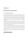
Figure 2.1.: Possible applications at home. (Adopted from: http://www.lingg-janke.de/
uploads/pics/eib-system-viele-funktionen.jpg
Lighting: Lights can be dimmed and switched on or off, either on demand or automatically. On
entering a room, all lights can be switched on, thus the entering person does not have to
search for the light switch first.
HVAC (heating, ventilation and air conditioning): Regulated heating makes it possible to
down-regulate heaters, if a window is opened. Together with automatic air ventilation,
each room can be tempered and aerated individually. If the sun shines directly into a room,
the shutters can be closed and ventilation can take away the additional heat.
Multimedia: Integrating multimedia allows the system to lower music volume, if the bell rings or
someone calls you. Turning on the TV can dim all lights to a pleasant level in the evening
and switch automatically to your favourite channel.
Security: Different surveillance devices can record if someone unknown enters the property and
tries to break into the house. Lights can be switched on in order to illuminate the intruder
Chapter 2. Related Work/Fundamentals
6
and take a picture of him. However, such disturbances can be prevented by simulating
activities in the house by switching lights on and off or by making noises.
These examples demonstrate the diversity of HA, by showing only a small part of all possibilities.
Technical innovations and an expanding product range will reduce limitations step by step and
enable its users to allow their dreams to come true.
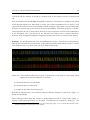
2.2.2. Structure
HA systems consists of many different devices, which can be connected by using different technologies. Each node can range between simple, pre-programmed behaviour and sophisticated built-in
intelligence. They can be classified in the following three categories:
Sensors: Sensors can sense changes or actions in the environment. After optional processing,
they pass the information to other devices. Typical sensors are: Motion sensors, cameras,
humidity sensors, temperature sensors.
Actuators: Actuators can influence the state of their surroundings. They retrieve their actions
from a paired sensor or logic device. Examples are: Shutter motors, power switches, light
dimmers, heaters.
Logic: Logic can interpret actions from sensor data and actuators’ states and construe actions
from them. Examples are: computers and heater controls.
light1
light2
shutter1
light3
light1
light2
Actuators
shutter1
BUS
Sensors
switch1
switch2
remote1
System 1
motion
sensor
switch1
switch2
remote1
System 2
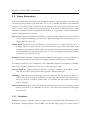
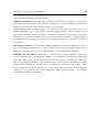
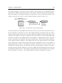
Figure 2.2.: Two HA systems with different topologies: The left one is a loosely connected system,
where each transmitter is assigned to only one or two receivers. The right system
uses a bus network that connects the devices bidirectionally to each other.
Different components of HA systems rely on different network technologies, which normally operate
decentralized. The amount of connections depends on the technology used. Figure 2.2 shows two
different systems: The left system is loosely connected, as each sensor is assigned to only one or
Chapter 2. Related Work/Fundamentals
7
two actuators. Connections are unidirectional, which means that actuators cannot send signals
but just receive them. Due to the missing acknowledgement, sensors do not know, if the actuators
received their signals and if they have switched to the desired state. Examples are Intertechno
(section 2.2.4 on page 14) and HomeEasy (section 2.2.4 on page 12). In the network on the
right hand side of figure 2.2, all nodes are connected bidirectionally over a bus-system. Package
losses and failures can be registered, allowing more sophisticated and reliable communication.
In contrast to unidirectional networks, bidirectional networks result in higher costs and higher
complexity. Nevertheless, this principle is widely used by wired solutions like KNX (section 2.2.4
on page 9).
The different bus systems are not compatible with each other and therefore the different automation systems cannot be easily linked together. However, they can still be connected via special
gateways. Some of these gateways are discussed in section 2.3.1 on page 19. For cost reasons,
home automation is normally restricted to a single bus system. In building automation, cost plays
a secondary role, therefore the most suitable type of bus is selected for each task. Examples of
other bus systems are TCP/IP, KNX, Power-Line Communication, CAN and RS485.
2.2.3. Transmission media
There are many different transmission technologies available for transmitting data over a bus
network, but the principles are based on just a few physical effects. By dividing the system
by the transmission medium into separate groups, there are three major representatives: wired,
optical and radio-based systems. Optical systems are mainly used in multimedia, for example in
a TV remote control. They are not common in HA, because a direct line of sight is needed and
they typically have a short range. By contrast, both wireless and wired systems are widely used.
Therefore, there is a brief summary of their pros and cons.
Radio-based systems:
Radio-based systems are widespread and represent the preferred transmission method in HA. The
high and rapidly growing popularity of such systems is primarily due to the following advantages:
High flexibility: Devices are not fixed to their initial deployment and can be relocated. This
allows the user to easily reposition the devices and add further nodes.
Easy to install: No laborious installation, which reduces time and costs. Wireless systems can
be put into operation very quickly.
Beside these advantages, there are several disadvantages:
Chapter 2. Related Work/Fundamentals
8
Security: Wireless systems are generally more insecure than comparable wired solutions. The
wireless media can be easily accessed by unwanted listeners or other interfering systems.
Most systems encrypt their data, but low-cost hardware often does not have this feature.
Hence, this offers the possibility for attacks and vandalism.
Reliability: Radio-based systems can malfunction, if the distance between two nodes is too high,
or if disturbances such as metal objects impair reception.
Directionality: Low-cost systems are usually unidirectional which means that devices can either
send or receive. Transmitted messages cannot be acknowledged and the state of receivers
cannot be read out. Therefore, errors can lead to an undetermined state of the system.
Bidirectional systems can register package losses and failures, but they are higher priced.
Tethered systems:
Cables are the classic transmission medium and have been since 1980, when the first wired automation systems came on the market. However, line transmission is gradually shifting towards
wireless solutions, as evidenced by the increasing number of wireless systems on the market. The
advantages of tethered systems can be summarised as:
Noise immunity: Screened cables are robust against electromagnetic interference, which enables
fast and reliable data transmission.
Power feeding: Devices can be supplied with power via cable, involving benefits in cost and size.
The main drawbacks of wired systems are the inflexibility and the resulting burdensome retrofitting
of new devices. Consequently, new customers often choose wireless-based solutions for equipping
already existing buildings. However, tethered system can be integrated into new constructions with
little effort, which can lead to a more reliable and secure solution than comparable wireless systems.
Examples of wired bus systems are: LAN, CAN, KNX, USB and power-line-communication (PLC).
2.2.4. Example Systems
In this section, some selected systems for home and building automation are introduced in order
to give a brief overview of current technologies.
X10
X10 is an open communication standard for power line based home automation systems. It was
developed in 1975 by the Scottish company Pico Electronics [8], with the aim of enabling the
Chapter 2. Related Work/Fundamentals
9
control of home appliances over the existing power grid. X10-based devices are inexpensive and
easy to install and are therefore very popular, especially in North America. Power line Communication (PLC) offers good flexibility, allowing the user to relocate their devices to some extent.
Nevertheless, X10 is not as flexible as comparable wireless systems, since the device must be
placed near power plugs. This excludes mobile devices, such as remotes or identification tags. As
a result of this limitation, there is a wireless standard called X10RF. It is based on X10 and both
systems can be connected by using gateways. X10RF is mainly used by outdoor devices, such as
motion sensors or door bells for areas, where no power line is accessible. However, the core of
the automation system, which includes all actuators, still uses PLC. There are many different X10
products on the market, but they can be divided into three main categories:
• Home Automation (switches, timers, shutter motors)
• Security (cameras, motion sensors, glass breaking sensors)
• Multimedia (universal remote, IR receiver)
Despite the wide product range, X10 suffers from many disadvantages: On the one hand, data
transmission is very slow2 , which results in a noticeable delay between actions. The use of gateways
or signal repeaters that are used to extend the range of the systems, increases this delay; as a
result time lags up to 1 s are not uncommon. On the other hand, the X10RF protocol is not very
scalable and due to the binding to the slow X10 PLC, it is not likely that X10RF is capable of
asserting itself.
KNX/EIB
KNX is an open communication standard for home- and building automation (ISO/IEC 14543,
CENELEC EN 50090, CEN EN 13321-1, GB/Z 20965) and a derivate from the European Installation Bus (EIB), BatiBus and European Home System (EHS). It specifies how to connect
the different KNX components and describes the protocol and the communication. About 200
companies worldwide distribute over 6000 KNX products [9], resulting in a huge product range.
The emphasis is on HVAC products, but there are also many solutions available for multimedia
and other fields of application. KNX components are highly priced and due to their relatively complex installation, they are used primarily in new buildings. However, the ability to integrate other
automation systems allows the user to upgrade the system with easy to install wireless devices.
Lee et al. [10] developed a ZigBee-KNX gateway to interface both systems and to enable integration of both wireless and wired HA systems. Another approach is presented by Windhab [11],
where a Java-based software is used to control KNX devices via mobile devices, using Bluetooth.
Furthermore, special gateways such as Miele@Home allow connections to dishwashers and wash2
around 20 bit/s
Chapter 2. Related Work/Fundamentals
10
ing machines, involving more complex controls. Other HA systems usually can only switch these
devices on or off. There are four types of KNX networks [12]:
• Two-wire line: TP-0 with 4800 kbit/s and TP-1 at 9600 kbit/s
• Power-Line Communication: with 1200 bit/s or 2400 kbit/s
• Radio (KNX RF): 868 MHz, FSK, 16 kbit/s, routing up to three participants
• Ethernet: KNXnet / IP
As already mentioned before, these different networks are often selected individually for each
application and can be combined via specialised gateways. This makes KNX a very robust system
and applicable for many tasks.
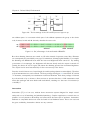
EnOcean
EnOcean describes an energy-harvesting wireless protocol, used primarily in building automation
systems. It harvests energy from motion, sunlight and temperature differences. Modules based on
EnOcean technology consist of an energy converter and ultra low power electronics. Since energy
harvesting modules yield only a very small amount of energy, typically around 50 µJ [13], devices
are constructed to consume as little power as possible. As a result, sensors often have only basic
functionality.
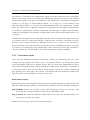
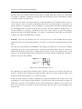
Figure 2.3.: three different energy harvesting modules for energy conversion: ECO200 is used
for motion (switches or make contacts), ECT310 uses temperature differences (for
sensors on windows or heating pipes) ECS310 uses light (suitable for all kind of
devices). Image source: http://www.enocean.com/en/energy-harvesting/
EnOcean technology is marketed by EnOcean GmbH, whereas the automation hardware is sold by
members of the EnOcean Alliance, which currently consists of over 100 companies 3 . Though the
emphasis is on HVAC products, there are many products available for typical HA applications. As
EnOcean devices are relatively highly priced, they are not as common in HA as other systems.
3
http://www.enocean-alliance.org/en/our_members/
Chapter 2. Related Work/Fundamentals
11
ZigBee
ZigBee is a specification for a suite of high level communication protocols based on IEEE
802.15.4 [14]: A Developing Standard for Low-Rate Wireless Personal Area Networks. It is
targeted at applications that require a long battery life, secure networking and low data rates.
Application and device profiles such as Home Automation, Smart Energy, Health Care and many
others are provided to simplify the configuration effort of an installation. A ZigBee network
consists of three types of devices:
• Coordinator: controls formation and security of a network
• Routers (full function devices): extend the range of networks
• End devices (reduced function devices): simple sensing and acting devices like shutter
motors or light switches
Star
Cluster Tree
Mesh
Pan Coordinator
Full Function Device
Reduced Function Device
Figure 2.4.: Different ZigBee topologies.
ZigBee can form star type networks, with a coordinator act as the root device, cluster-tree or
generic meshed networks [15]. Meshed networks provide high robustness, whereas the star types
consume less energy. The Cluster-tree topology is a mixture of both star and mesh networks. The
network type is chosen by the used products and their application field. ZigBee products are sold
by members of the ZigBee Alliance, which includes over 400 different companies 4 . As a result
there is a large number of different products for all application fields.
4
http://www.zigbee.org/About/UnderstandingZigBee.aspx
Chapter 2. Related Work/Fundamentals
12
HomeEasy
HomeEasy (HE) is a simple wireless home automation system produced by the British company
CH Byron 5 . It is designed for simple tasks such as switching lights on and off and time scheduled
switching; complex controls cannot be realized. HE devices are inexpensive and can often be
found in local hardware stores. The product range includes devices to control:
• Lights: on/off switching and dimming.
• Electrical appliances: on/off switching by connecting or disconnecting them from the mains.
• Multimedia: TV/DVD/Receiver via optical IR
• Security: Motion sensors and access control systems
HE devices are marketed by Byron outside the EU and by ELRO6 within the EU, as well as by some
other national companies. Some of these companies sell their own automation systems, which do
sometimes have a remarkable resemblance to HE, for example Klik on Klik off, Bye Bye Standby or
Nexa. These systems can partly communicate with HE devices, but there is no true compatibility.
Therefore, they will no longer be concerned within this work. There are incompatibilities within
the different HE devices, due to the lack of standardization of the protocol and significant changes
to hardware over the course of time. The initial protocol (figure 2.5) is similar to the protocol of
the HX2262 chip, as used in Intertechno (section 2.2.4 on page 14); later versions use a dedicated
microcontroller. There are great differences between the UK-series (sold in the non EU) and the
EU series. Both series have a completely different protocol and are incompatible despite a similar
product range. Within the UK series, there are some other incompatibilities due to different
protocols and the encryption of data for some products. This leads to a complex list of which
devices can communicate with each other. However, the manufacturer states that all devices are
compatible with each other, which is probably true for the current series and not for the many
different versions, which can still be found on the market. This work will only consider devices of
the EU-series.
Specifications HE devices form loosely connected networks, in which sensors are normally linked
to just one or two actuators. Sensors can theoretically be connected to an infinite number of
actuators, whereas an actuator can only relate to a maximum of six sensors. This can be explained
by the fact, that an actuator can only store a maximum of six addresses in its memory. Connections
are established by learning: the actuator is put into learning mode, which will tell it to store the
next received valid address into its memory. Once the address is saved, sensor and actuator are
5
6
www.chbyron.eu
www.elro.eu
Chapter 2. Related Work/Fundamentals
13
connected until the memory is cleared by a manual reset. If the memory was full, connection will
fail.
Data is transmitted via 433.92 MHz using OOK modulation. Connections are unidirectional, which
means that participants can either send or receive. As a result, transmitters are not aware of each
other and the receiver cannot acknowledge received messages. This lowers costs, because radio
modules are simpler, but it also leads to increased unreliability. Therefore, products of the EUseries send their data up to seven times, whereof at least one must be received. Data transmission
is not encrypted; just a few devices of the UK-series use rolling code to encrypt their data.
However, these encrypted messaged need special receivers and cannot be read by other devices.
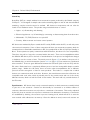
Protocol As already mentioned, there are different protocol types. Since they are all proprietary,
different data streams were recorded with a logic analyser and decoded manually. Figure 2.5 shows
three different protocols, which were sent by a HE853 USB dongle.
Figure 2.5.: Three different HE protocol types. The short bit at the start is a sync pulse, which
slightly increases the sensitivity of receivers.
a) encrypted UK-protocol with 29 bit
b) UK-simple protocol with 25 bit
c) Snippet of the 58 bit long EU-protocol
Each Bit is represented by one transition with two different timings for each level. Figure 2.6
shows the bit timings.
Every message is 58 bit long and contains a unique address as well as a state code. Figure 2.7
depicts a typical message from an on/off-switch. The address code consists of a fixed part
7
7
and
This part stayed the same for all combinations of device and group codes. It is not certain that this part is really
fixed, but the author could not prove the opposite.
Chapter 2. Related Work/Fundamentals
14
"0"
980
"1"
320
320
980
275
1320
UK
275
275
EU
Figure 2.6.: The bit timings of the UK and EU protocol types in µs.
two address parts. It is uncertain which part of the address represents the group or the device
code, however, bit 48 and 49 obviously describe the state code.
on: 1100011110011011000111101001110001111101001101110011000111
off: 1100011110011011000111101001110001111101001101101011000111
fixed
adress1
state adress2
Figure 2.7.: On/off-message of the wall switch HE307EU.
Note that dimming functions use normal on/off-codes instead of separate control bits. Dimmers
can consequently be controlled by every type of transmitter, allowing higher flexibility. For example
the dimming unit HE888 will start with the last saved brightness when turned on. By sending
a succession of on-messages, the brightness will decrease slowly until the output is turned off.
Turning the device off and on again, will restart the dimming process from maximum brightness.
The output level is saved automatically for the next start-up of the device.
Since the 0 and 1 bits are not of equal length, the whole package duration varies slightly. Therefore
no fixed transmission rate can be stated. The data package from figure 2.7 contains 24 "0" and 34
"1" elements, consequently its transmission would need 67.43 ms. Each data package is followed
by a short break of up to 10 ms to allow receivers to process their data. A full transmission with
seven data packages and seven breaks will need 542 ms, resulting in a data rate of 1.84 actions/s
or 107 Bit/s
Intertechno
Intertechno (IT) is a low cost, wireless home automation system designed for simple control
tasks, such as on/off switching and scheduled switching. Complex regulations or controls are not
possible. It is very similar to HomeEasy and offers about the same span of products. Intertechno
hardware or compatible devices can often be found in local hardware stores. Due to low cost and
the great availability, Intertechno devices are very common.
Chapter 2. Related Work/Fundamentals
15
There are two different types of devices: The classic system, which uses manual address selection
and a newer system with learning function. In this work, only the manual system is considered.
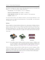
Figure 2.8.: Two IT receivers: classical devices with manual address selection on the left and a
newer one with learning capability on the right. (source: www.intertechno.at)
Specifications The address range of the classic version includes four bits for the family code
and four bits for the device number; accordingly a total of 256 different devices can be addressed
individually. The family code can range from A to P (equals 0 to 15) and has the purpose to
group devices to simplify numbering and classification. These groups can be switched as a whole
by some remotes. Both codes can be set via rotary encoder or dip switches. Transmitter and
receiver can be linked by setting the same address on both units (family and device code). Units
with manual address selection have a built in IC HX2262 (transmitter) or HX2272 (receiver) as
their centerpiece. These chips were designed for remote controls, and are commonly found in a
variety of products, such as garage door openers or in infrared remote controls. They have 12
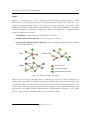
tri-state inputs which can be used as address or data lines (see figure 2.9). Self-learning devices
use a dedicated microcontroller instead.
familycode
familycode
A0..A3
A0..A3
HX2272
HX2262
A.. P
A.. P
device number
device number
A4..A7
Data
out
Radio
Data
Radio in
A4..A7
0..15
keys
0..15
outputs
D0..D3
enable
D0..D3
Figure 2.9.: Diagram showing the structure of a HX2262/72 couple.
By using the popular HX2262 chip, Intertechno devices are often compatible to other automation
Chapter 2. Related Work/Fundamentals
16
systems, above all to Asian products, where this IC is widely used due its low cost. This makes
it possible to upgrade an automation system with non-Intertechno devices. Nevertheless, reliable
cooperation cannot be guaranteed.
IT devices form loosely connected networks, in which transmitters are normally linked to just one
or two receivers. Due to the manual addressing, each device can theoretically be connected to an
infinite number of counterparts. Data transmission is unencrypted and OOK modulated within
the 433.92 MHz band. Devices can either send or receive, thus the transfer is unidirectional. To
increase reliability of reception, commands are sent four times, whereof at least two messages
must be received for successful switching. The range is comparatively small with only 30 m (line
of sight), but can be increased with a repeater.
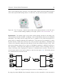
Protocol There are two different protocols: The open protocol of the HX2262 and the newer,
proprietary protocol of self-learning devices. The latter one will not be examined further in this
work.
The protocol is generated by the HX2262 IC. By pulling the enable-pin to Vss, the IC transmits
sequentially the states of its 12 inputs and a synchronization pulse, which serves as a spacer for
subsequent repetitions. Each state is composed of two pieces of data, each lasting for four cycles
(figure 2.10). A synchronization pulse corresponds to the data element 0, which was extended to
32 bars. The cycle time is 400 µs.
Data „0”
Data „1”
Figure 2.10.: Data elements 0 and 1.
An address pin can assume three different states, whereas a data pin can only have the state Vss
and Vcc. The state float means that the input is neither Vss nor Vcc, but it is unconnected. Float
is represented by 01 (see figure 2.11 on the next page).
A data package consists of 25 bits, consequently a single transmission lasts 51.2 ms and a full
transmission of four packages needs 204.8 ms. On the receiver side, incoming data streams are
shifted into the input of the HX2272 and the received address is compared to the internal one
with each occurrence of a syncbyte. If both are the same, the data pins are set according to the
received ones.
Chapter 2. Related Work/Fundamentals
Input Vss: „00”
Input Vcc: „11”
Input Float: „01”
Sync: „0”
Figure 2.11.: All possible bit combinations.
17
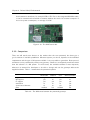
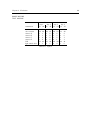
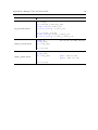
Medium
Network size
Data rate
Range indoor[m]
Range outdoor[m]
Bi-/Unidirectionally
Security
Costs
Connectivity
Installation overhead
RF 433 MHz
28
100 bit/s
5
30
uni
none
low
low
low
RF 433 MHz
245
500 bit/s
5
30
uni
none
low
low
low
PLC, RF 433 MHz
28
20 bit/s
30 (X10RF)
100 (X10RF)
uni/bi
none
low
low
low
X10
RF 868 MHz
232
125 kBit/s
30
300
uni/bi
low
high
low
low
EnOcean
RF2.4 GHz
216
250 kBit/s
10
75
bi
medium (AES)
medium
medium
low
ZigBee
Table 2.1.: The presented automation systems at a glance.
Intertechno
HomeEasy
TP, RF868 MHz
216
9.6 kBit/s
700
700
bi
high (EIBsec)
high
medium
high
KNX
Chapter 2. Related Work/Fundamentals
18
Chapter 2. Related Work/Fundamentals
19
2.3. Home Automation Gateways
A gateway is a linking device between two or more different network technologies. It provides
unified interfaces and protocol conversion methods to enable different participants to communicate
with each other. The gateway implies an abstraction layer, as the participants do not have to
know details about the protocol and characteristics of the other side. A HA gateway is usually a
piece of hardware, consisting of a processing unit and different interface modules. The complexity
depends on the number of supported systems as well on the systems themselves. There are a wide
variety of gateways, which can provide very different functions. In this work, they will be divided
in two main categories:
HA-HA gateway: HA-HA gateways are focused on connecting different HA systems among
themselves. Examples are X10RF to X10 or ZigBee to KNX [10] gateways.
HA-PC gateway: HA-PC gateways aim to incorporate computers into the automation system,
by providing interfaces like serial port, USB or LAN. Such gateways often support more than
one HA protocol in order to be applicable to many tasks and to address a high number of
potential buyers.
Connecting different transmission technologies like KNX TP and KNX RF (section 2.2.4 on
page 9), allows the user to select the most appropriate system for each task. This combines
their advantages and leads to increased robustness. Furthermore, automation systems can be upgraded with hardware from different systems. This can be necessary if a product is discontinued
or a certain device does only exist for another HA system. Apart from that, gateways can have
typical computer interfaces, like Ethernet or USB, allowing much more extensive control possibilities. The drawbacks are relatively minor compared to the advantages. Due to an additional device
in the information chain, some functions like signal repetition will cause a delay and increase the
latency of the whole system. Another point against the acquisition of a gateway is the price which
can increase up to several hundred euros for high class systems.
2.3.1. Example Gateways
This section will present some selected HA gateways. Since this work aims to integrate HA into
an Intelligent Environment, in which computers play a central role, only HA-PC gateways are
considered. They must be able to connect to 433 or 868 MHz wireless systems and should support
many different protocols. It is also desirable that the device is low cost and easy to use. All the
four presented gateways fulfil these requirements and could be used for the practical part of this
work (chapter 3 on page 27 Concept).
Chapter 2. Related Work/Fundamentals
20
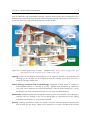
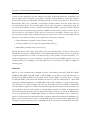
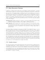
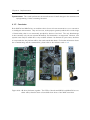
Figure 2.12.: Three different gateways: RFXtrx433, TellStick and CUL.
RFXCOM RFXtrx433 8 : USB transceiver for 433 MHz systems with an integrated antenna. It
is supported by a great deal of commercial automation software and knows a very large
number of different wireless protocols. A built in CSMA-CA mechanism enables collision
detection and automatic resending of lost data packets. Although, this first error detection
reduces the risk of error, it does not guarantee error free transmission. In addition, RFXCOM
offers a free software development kit with VB.NET examples.
Telldus TellStick 9 : Small, compact USB dongle with an external SMA antenna for 433 MHz
systems. It can be controlled by Telldus software and includes an app, which is, however,
only available for Apple users. Internet access is possible through Telldus Live, but it
requires port forwarding and a server. There are three different versions of the Telldus
Stick: a simple unidirectional transmitter and two bidirectional transceivers with extended
functionality. However, the top model, the TellStick Net, provides a LAN interface and can
be run without a PC.
Busware CUL
10 :
A small and universal USB transceiver for either 433 or 868 MHz systems. The
centerpiece is an 8 bit Atmel microcontroller (ATMEGA32U4) connected to a TI CC1101
RF transceiver. The firmware is open-source, thus it can be easily modified and adapted
to solve specific problems. CUL is preferably controlled via the open software FHEM which
runs on some routers, for example, the 7390 Fritzbox or Linux systems, for instance the
Rasberry Pi.
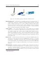
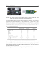
WifiControl 433: A multipurpose gateway for 433 MHz systems, developed by the author in
the students research project Implementation of an Ethernet gateway for wireless home
automation. It supports Intertechno and HomeEasy EU devices and can be controlled via
USB, USART, SPI, IO and WLAN. In addition, it can act as an interface converter and send
8
http://www.rfxcom.com
http://www.telldus.se/
10
http://busware.de/
9
Chapter 2. Related Work/Fundamentals
21
data between its interfaces, for example USB to SPI. Due to the integrated WLAN module,
it can be accessed and controlled via internet without the need of an external computer. It
has a low power consumption, an average of 0.5 W.
Figure 2.13.: The WifiControl 433.
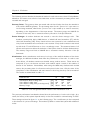
2.3.2. Comparison
There are still much more devices on the market than the ones presented, but these give a
good overview of available possibilities. Whatever system you choose, depends on the individual
requirements and the type of HA system available. It is not possible to generalize. Basic protocol
translation can be performed by almost every gateway. Selection is consequently much less critical
than the selection of a HA system. For most users, the available software is most important,
whereas it is essential for developers to be able to change and use the gateways without the
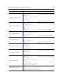
supplied software. Table 2.2 summarizes the presented systems.
supported number of HA systems
HE support
IT support
standalone
open-source firmware
prize
RFXtrx433
TellStick
CUL
WifiControl433
high
yes
yes
no
no
medium
medium
no
yes
no
no
low
low
yes
yes
no
yes
medium
low
no
yes
yes
yes
low
Table 2.2.: The differences between the presented gateways.
Chapter 2. Related Work/Fundamentals
22
2.4. Middleware
Middleware describes software that facilitates data exchange between applications within the same
environment, or across different hardware and network environments. It forms an abstraction layer
that hides complexity and allows communication, without having detailed knowledge of the internal
structure of the opposite site [16]. In addition, middlewares often come with tools and services to
manage, monitor and administrate the system. This allows the developer to create independent
modules, as the software no longer needs to consist of one single part. These software modules
will be recognized externally as one unit, making distribution transparent [17]. This simplifies
programming, since the total complexity is reduced, and the development process optimized. It
also relieves the actual application software, as the program and the middleware can be handled
separately. However, many middleware systems are very complex and therefore difficult to manage.
Small programs can be overwhelmed by greater middleware, as the middleware could easily be
the multiple size of the program itself. Further disadvantages are the reduced overall performance
and the increased consumption of resources.
Driver
Software
Middleware
Hardware
Figure 2.14.: Middleware as an communication layer between software, hardware and a driver.
Middleware is particularly useful as a connection in distributed systems, such as Intelligent Environments with access from smart phones and tablet PCs [18]. Many types of middleware have
been proposed to be used in such systems, but none has been accepted as standard yet [19]. This
is partly caused by either the lack of special functionality or by a great plenitude of already existing
systems on the market, which makes it difficult to find acceptance for new solutions. In addition, a vast amount of constant work is needed to maintain a middleware over time to maintain
its compatibility with the latest computing trends. Examples for middleware are frameworks like
.NET, Web services, print servers and drivers, as well as general middleware like CARMEN [20],
GAIA [21] and MundoCore [22].
2.4.1. Example Middleware
This section introduces selected middleware systems which are suitable for Intelligent Environments
or Home Automation.
Chapter 2. Related Work/Fundamentals
mBS Smart Home
11
23
is a platform-independent, Java-based framework, based on the OSGi
middleware. It is optimized for use in embedded products, such as routers, gateways and
mobile phones, and offers an SDK and other tools for product development. Various automation systems are supported such as ZWave, ZigBee, UPnP, KNX, X10, and another
set of external hardware, for example Webcams. mBS Smart Home SDK comes with a
set of additional components, which provide services such as SMS and email notification,
multimedia extensions, web server and a web framework for web based interfaces [23].
MiddleWhere [24] is designed for location-aware applications as it provides advanced location
data and facilitates the use of different location sensing techniques. MiddleWhere stores
its data in a spatial database consisting of sensor information and a representation of the
physical space. In order to reduce conflicts and merge different sensor values, it has a
reasoning engine, which uses sensor model and spatial information to determine an object’s
location with a certain probability. The location model is hierarchical and defines three
different kinds of locations: points, lines and polygons. Each entry is represented as GLOBs
(Gaia LOcation Byte-string), which contain coordinates (x, y, z) and a symbolic name. For
example a light can be saved as Building2/1/1913/Light1 or as Building2/1/1913/(1,5,3),
meaning that Light1 is located in room 1913, floor 1 of building 2 at the coordinates (1,5,3).
In this case, the light can be defined by a point. Polygons are used to present rooms and
other complex shapes like chairs, tables and spaces, while lines can represent doors.
MundoCore [22] is a light-weight infrastructure designed for pervasive computing. Due to its
low footprint of approximately 42 kB
12 ,
it can be used on a wide spectrum of different
devices, ranging from servers to small embedded systems. It is based on a microkernel
design and offers functionality like dynamic reconfiguration and common APIs for several
programming languages (Java, C++, Python, C#). MundoCore uses different communication abstractions, such as publisher/subscriber, services and XML RPC, which are similar
to the functions offered by ROS. Moreover, it provides automatic peer discovery allowing
nodes to detect each other.
2.4.2. Robot Operating System (ROS)
The Robot Operating System (ROS) is an open source middleware for robotic systems. Its
development started in 2007 under the name switchyard by the Stanford Artificial Intelligence
Laboratory for the STAIR project [25]. In 2008, the project was taken over by Willow Garage. As
a result ROS inherits the drivers, navigation system, and simulators from the Player project, vision
algorithms from OpenCV, planning algorithms from OpenRAVE and different functions from many
others [26].
11
12
http://www.osgi.org/Spotlight/MBSSmartHome
https://wiki.tk.informatik.tu-darmstadt.de/bin/view/Mundo/AboutMundo
Chapter 2. Related Work/Fundamentals
24
The philosophical goals of ROS can be outlined as13 :
• Peer-to-peer topology avoids a central communication server, which will cause unnecessary
traffic and can be problematic in heterogeneous networks.
• Tools-based: As ROS is based on an adapted microkernel, it offers a large number of small
tools to run and build ROS components as well as tools to manage complex systems.
• Multi-lingual: Larger projects are usually developed by several people, who often use their
own programming languages. In order to facilitate this cooperation and reach a wider
audience, ROS nodes can be programmed in multiple programming languages. (C++,
Python, LISP and Java)
• Thin: Code could be reusable in many cases, but it is often wrapped up in middleware,
which makes it hard to extract it. ROS, therefore, performs modular builds in the source
code tree to keep dependencies low and facilitate the reuse of code.
• Free and Open-Source: ROS is released under the BSD license making it free for private
and commercial use. This encourages many people to use it, resulting in a broad community
and a number of available packages for fields of applications.
ROS is primarily designed for robotic applications and is not specialised for use in Home Automation or Intelligent Environments. However, both HA and IE can be described as ImmoBots [27],
which are robots with typical characteristics of a robot, such as sensor richness and autonomy, but
are not mobile. Roalter et al. describe in [16], how ROS can be used in Intelligent Environments.
Technical aspects
ROS consists of different main components: nodes, messages, topics, services and the ROS master.
Nodes are small software modules that perform computation. They can represent processing
algorithms and different functions, such as drivers for sensors and actuators. A system usually
consists of many nodes, which communicate over topics and services. This fine subdivision makes
ROS programs very modular and easy to manage.
Topics are used to exchange data between different nodes. A node sends data by publishing
it on a certain topic to which all interested nodes can subscribe and receive the data. Every
topic can have multiple publishers/subscribers and every node can publish/subscribe to multiple
topics. This asynchronous data transmission abstracts the transmitter and receiver side, therefore
publisher and subscriber are not aware of each other. Topics consist of a name and a message
type.
13
http://www.generationrobots.com/ros-robot-operating-system,us,8,74.cfm
Chapter 2. Related Work/Fundamentals
25
Services are for communication between two nodes, whereas topics are for many-to-many communication. Nodes can host a service server under a string name and a client can send a request
and wait for the response. Services are composed of a name and a request and response message.
They are synchronous and therefore do not abstract sender and receiver.
Node A
Node B
Node A
Node B
request
event
handler
wait
handler
response
(a) Asynchronous event
(b) Synchronous call
Figure 2.15.: Differences between a topic (a) and a service (b). Adopted image from [28]
Messages are strictly typed data structures. They can be composed of primitive data types, such
as int, float, boolean, etc. as well of other messages and arbitrarily deep nested arrays of messages.
They are specified in text files, which are generated into headers for all supported programming
languages during compilation. An example of two different messages is given in figure 2.16. To
ensure, that both sender and receiver have the same message files and not different versions, each
message contains a MD5 checksum, which has to match for a successful transmission.
bool sender
int id
string name
myMessage data_struct
device_has_been_seen.msg
bool sender
int id
--myMessage data_struct
Request
Response
get_device_data.srv
Figure 2.16.: Two example messages: One topic message (left) and one service message (right).
Request and response are saved in the same file, but are separated by “- - -“. MyMessage is a custom message from another .msg file.
The ROS-Master is a central declaration and registration service, which keeps track of all nodes,
topics and services and makes it possible for nodes to find each other and exchange data. The
Master uses XML-RPC, providing all information encapsulated in XML files. When starting a new
node or creating a new topic or service, registration data is send to the Master and saved in a
database. Clients can request this information by sending a service or topic name and they will
get a list of subscribers or the address of the service server. The Master is not involved in the
data flow; it just exchanges information, allowing the node to establish peer-to-peer connections.
Image of ros network generated with rxgraph.
Chapter 2. Related Work/Fundamentals
26
There exist further useful tools and functions:
Logging and Playback: ROS supports two different mechanisms for logging and playback of
data: the rosout topic and bag files. The first mechanism is a topic called rosout. It will display
information sent from all nodes and save them in textual log files.
The second mechanism is called rosbags. In contrast to rosout, bags allow the storage of all
published messages, not only the output of specific logging functions. These messages can be
played back afterwards, making it possible to simulate real data and custom setups, even if the
hardware is not available. In addition, data can be played back in real time or sped up, which is
a useful feature for debugging. Bags can only store messages from topics, as service connections
are invisible.
The Parameter Server is a centralised database, designed for sharing data between all nodes.
Due to its relatively slow speed, it is mainly used for static or slowly changing data, such as
settings and constants. It is part of the ROS-Master and is implemented in XML-RPC.
Roslaunch and Namespaces: Roslaunch is a tool for easily launching multiple nodes locally
or over SSH with given parameters and settings. The configuration is defined in XML-based
launch-files, which cover options, such as to automatically respawn processes, once they have
died, and uploading parameters to the parameter server. ROS supports namespaces to support
the hierarchical arrangement of nodes, topics and services and to prevent name conflicts. There
are three different namespace models, one for each node, topic and service. Each namespace
consists of one root element and various sub-elements, which are separated by "/", for example
"/building2/room1913/power-plug2".
Chapter 3.
Concept
This chapter covers basic concepts and ideas about the integration of Home Automation (HA)
components in Intelligent Environments (IE). It aims to give an insight into the decisions made
to improve general understanding and prepare the reader for chapter 4 on page 36.
3.1. Basic structure
Modern environments are often equipped with different technologies. The autonomous and intelligent processing of tasks in these environments is a challenging task, as pre-existing HA technologies
cannot be integrated directly. Therefore, we first need to establish a standardized communication
basis, enabling IE to understand and interact with HA components. Figure 3.1 illustrates the basic
structure of the communication chain.
Homeautomation
Hardware
HA-PC
Gateway
Software
Processing
Hardware
Gateway
to IE
Software
Figure 3.1.: The basic structure of the communication chain.
Many IE are computer-based, which can take over compute-intensive tasks, such as connecting
the individual participants as well as deriving higher reactions. Since the IE at the research group
is computer based as well, the first step is to connect HA devices to a computer. This is done
via HA-PC gateway, as mentioned in section 2.3. The next step is software that prepares and
processes the data and finally enables the interfaces to connect to an IE. These different parts are
elaborated in the following sections.
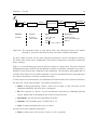
Another approach to illustrate the basic structure is depicted in Figure 3.2. It shows the communication chain as a set of different layers, which gradually abstract the information. Each layer
forms a consistent module, providing a specific function to abstract information for the next layer.
27
Chapter 3. Concept
28
These modules can only be used as a whole; no direct intervention is possible allowing communication only before or after the module. This strict division results in increased flexibility, allowing
evaluating or changing each module separately. This is favourable for simulation or debugging, as
every module can be replaced with a simulation or logging program that replaces the functionality. This advantage is used in the final evaluation in chapter 5 for simulating and evaluating the
system. However, this segmentation also has its drawbacks. On the one hand, information has
to pass through every layer to reach its final destination. This results in increased data traffic
as well as an increased latency. Furthermore, this can cause a noticeable delay between events
and actions, lowering the user’s acceptance. On the other hand, each layer needs interfaces to
communicate with its surrounding layers. This increases the amount of code being implemented
on the module, because of the algorithms for communication and synchronization.
communication
abstraction layer
communication
possibilities
for every layer
Software
abstraction layer
abstraction layer
gateway
Hardware
Figure 3.2.: Layer model: Each part of the software chain can be seen as an abstraction layer.
The grey field displays a middleware.
To reduce the amount of code needed for communication, an existing middleware was used. In this
implementation, ROS was chosen, as it is already in use for IE research at the institute. It offers
a wide range of useful tools and functionalities, making it perfectly suitable for this work. These
are for example a working publisher/subscriber architecture, which supports the exchangeability
and strict boundary of each layer.
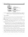
The bottommost block of the layer model (figure 3.2) is the HA-PC gateway, which represents
the first level of abstraction, as it converts the binary data packages of HA devices into a serial
data stream. All higher layers are software modules that are embedded in the middleware. The
highest layer acts as an interface to the IE. To enable a simple and fast connection of HA to
IE, different software modules were implemented in order to take on the processing of data. The
software components and the abstraction of HA devices are elaborated in the following sections
of this chapter.
Chapter 3. Concept
29
3.2. Hardware
Many different HA systems are available on the market, but in this work only two of them are
considered: HomeEasy (HE) and Intertechno (IT). HomeEasy was chosen because it has already
been used at the research group. Several devices, such as light switches, had already been
installed for everyday usage and there had also been approaches to integrate HomeEasy into the
Cognitive Environment [4] by developing an Arduino based transceiver1 and a ROS package for
the HE853EU USB dongle2 . As a second HA system, Intertechno and other HX2262 relatives
were chosen, because they are cheap and widely available. Both systems are very simple and lack
further intelligence. This makes them suitable for easy integration in IE.
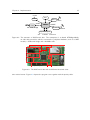
The gateway WifiControl 433 was used, as it had been designed exactly for this task by the by
the author in a recent student project "Implementation of an Ethernet gateway for wireless home
automation". Nevertheless, it had to be enhanced to be used out-of-the-box in the IE.
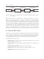
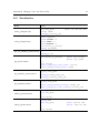
3.3. Software
The software shown in Figure 3.2 consists of several parts, each of which has only a single task
to ensure maximum flexibility. However, this would rapidly increase data traffic, therefore a
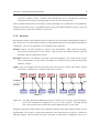
compromise was made and the software is divided in just three ROS nodes as shown in Figure 3.3:
gateway driver, device manager and visualization.
processing and abstraction module
to gateway
gateway
driver
device
manager
visualization &
namespaces
to IE
ROS
Figure 3.3.: The software part of the communication chain, which contains three ROS Nodes.
ROS serves as a link between the nodes connecting them and offering the interfaces
for the IE. The gateway, however, is not directly connected to ROS; instead it is
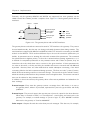
connected to the gateway driver node, which allows indirect access over ROS.
The gateway driver node is the first abstraction level. It aims to provide a unified interface
to exchange raw protocol data, so that the next software layer does not need to know specific
information about the used gateway and the protocol timings. As a result, different gateways can
be combined and multiple gateways can run concurrently.
1
2
http://mediabox.grasp.upenn.edu/roswiki/doc/api/homeeasy_transciever/html/index.html
http://mediabox.grasp.upenn.edu/roswiki/doc/api/homeeasy_dongle/html/index.html
Chapter 3. Concept
30
The device manager node connects HA protocols with a set of data, which contains the most
important information about the device. The data is stored in a XML database. Special lookup
and control functions allow the HA system to be managed by changing entries in the database.
Thus, the device manager allows device handling without knowledge of their protocol codes and
types (HE or IT) as well as keeping track of the current state of each device.
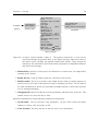
The visualization node offers visualization functions for graphical control over the HA system.
In addition, it provides a namespace service, which allows devices to be assigned to different
namespaces. These namespaces can represent different locations, such as buildings, floors and
rooms. As a result, devices can be divided in groups depending on their location. This is useful
for larger networks, as information becomes more readable and local devices can be filtered.
The visualization node offers abstracted device and location information, but nevertheless, it can
sometimes be useful to access other information, like protocol data, too. The higher software
layers do not hide all previous layers, so each nodes can always be accessed by their ROS topics.
Since ROS topics conceal receiver and sender, the internal structure is not directly visible from
the outside; the user will rather see a bunch of different topics and can decide which degree of
abstraction he wants to use.
3.4. Device Management and Abstraction
The communication chain shown in Figure 3.1 converts raw binary data to a human readable
string format with namespaces, for example "0x000AA8" → "dormitory/table_light". It aims to:
• Create human readable topics and data structures to allow an easy and intuitive use of the
data.
• Hide information such as protocol timings, addresses of devices, etc. to relieve the IE from
unnecessary data.
• Accelerate the development of new software, since little to no foreknowledge is required on
communication details of HA systems.
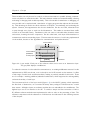
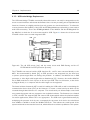
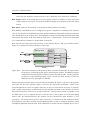
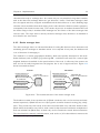
The abstraction is mainly performed by the software, which consist of three parts. Figure 3.4
shows the different abstraction stages for an example, where a remote control turns a light on.
The gateway receives the on-code "IT AA8A" and sends it to the gateway driver, where protocol
type and data are separated. The device manager then compares the data with its database and if
a matching entry exists, it delivers a detailed data structure to the visualization node. There it is
compared to a namespace database and if a match occurs, the full namespace with device name
and new device state is provided. Note, that the database of the visualization node contains no
device information. It consists of a list of namespaces with a list of device names. This simplifies
Chapter 3. Concept
31
devicelist
wlan
usb
gateway_driver
protocol
data
devicemanager
visualization &
namespace
requests
n/devicelist
n/requests
database
database
Hardware
Protocol
Device
Namespace
IT 000AA8
Protocol: IT
Code: 000AA8
name: table_light
type: light
state: on
location: myroom
name: myroom/table_light
state: on
last seen: today, 12:20:48
Figure 3.4.: The information chain in more detail: Each node abstracts the data a bit further
allowing to convert the initial binary data into human readable information.
the data output, because only the most important information, like the namespace (location),
the device name and its state, are displayed. The full device information can still be accessed via
device manager.
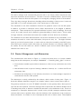
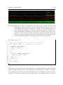
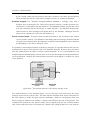
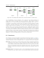
Figure 3.5 on the following page takes the previous example to a deeper level. The device manager
distinguishes between receivers and transmitters; therefore its database is divided in two parts: a
database for the receiver and a database for the transmitter. The separation sympathizes with IT
and HE, where devices can be either transmitter or receiver and facilitates device management as
the software abstraction can better represent the reality.
In some respects, the data structure of transmitters and receivers share some common information,
but they also contain special details. The common information is:
• Name: A string representing a device. Each name is unique, so that each entry can be
addressed individually and there are no ambiguities.
• ID: The unique id of a device. Can be used instead of the name for addressing database
entries. Mainly used for speeding up the internal lookup functions.
• Description: An optional string describing the device.
• Protocol: The used HA system. Currently HE or IT.
• Type: A string representing the type of a device.
Receivers have some additional information:
• State: Current state of the receiver. Can be on, off or unknown.
Chapter 3. Concept
IT 000AA8
gateway
protocoltype: IT
data: 000AA8
gateway_driver
32
name: "table_light"
id: 12
description: "light on my table"
protocol: IT
type: "light"
state: off
on
default_state: off
senderID_list: 3, 4
default_sender: 3
changed_by_ID: 3
3
myroom/table_light
changed_to: on
sender_used: myroom/remote1
visualization
name: "remote1"
id: 3
description: "Philip's remote"
protocol: IT
type: "remote"
onCode: "000AA8"
offCode: "000AA0"
current
time: 11:24
date+time
date: 16.02.2013
device_manager
Figure 3.5.: A remote control switches a light on. The gateway receives the on-code and its
data flows through the gateway driver to the device manager, where the entries of
the remote control and light are updated (marked with arrows). These changes are
delivered to the visualization node and are finally outputted as a simplified namespace
and device state message.
• Default State: Optional, can be used to set all devices to a certain state, for example when
powering up the system.
• Sender ID List: A list of senders, which are connected to the receiver.
• Default sender: The id of one sender of the Sender ID List. During a change request of a
receiver, the on/off-codes of this sender are used for switching the device. Can be useful if
the other transmitters on the list are connected to multiple receivers, so these other receivers
are not changed unwittingly.
• Changed by ID: Optional, holds the id of the transmitter, which was seen as the last. This
enables access of its data, like date or time.
Whereas transmitters have these following additional characteristics:
• On/off-codes: The on/off-codes of the transmitter. As the codes contain the unique
address of a device, they are unique as well.
• Time and date: The time and date of the last action of the transmitter.
Chapter 3. Concept
33
The assignment in different structures makes certain assumptions: On the one hand, transmitters
do not have a state, which corresponds to IT and HE. Instead, they store the date and time of
the last action, which are continuously updated. On the other hand, receivers do not have any
on/off-codes and are therefore associated with transmitters that have these codes. This linkage
grants both sides access to the data of the other side. For example, the time when a receiver
changed can be obtained by reading out the time of the transmitter with the changed_by_ID. It
is also possible to tell whether the last message of a transmitter was an off or on-code by reading
out the current state of the associated receiver. A disadvantage of this separation is that these
indirect data requests require two accesses to the database and are therefore a bit slower than one
single access. However, this makes both structure types smaller and there will be less data traffic.
Frequently used information such as the protocol type is therefore saved in both structures.
3.5. Requirement Analysis
The requirements of the overall system are greatly dependent of the used HA system, in this case
of IT and HE. The following points play an important role for the software performance and are
therefore examined more closely:
• Latency: Are there noticeable delays between different actions? Does this make the use of
the system unattractive for users or even unstable?
• Computing power: Are there worst case scenarios where the computer may be overloaded?
Do data packages accumulate in the message buffers and can these buffer overflow?
• Bandwidth requirement: How much traffic is caused by the synchronization between the
nodes? Can it be so large that slow internet connection cannot be used or they would cause
a great delay?
In order to assess these points, this section will consider the characteristics of IT and HE systems.
Both IT and HE devices form either very small networks or highly spatially distributed networks.
This is due the fact that the single 433 MHz transmission channel, the low transmission rate
and a missing error correction lead to a growing number of package collisions, which makes
large, spatially confined networks very unreliable. Theoretically, IT supports a network size of 28
and HE up to 245 members, but these high numbers are not primarily intended to allow large
networks. Instead, they serve to prevent the coexistence of devices with the same addresses
in neighbouring systems to minimize the interference between them. Small premises like rooms
typically do not have more than 20 different devices installed. These small networks are favourable
for the performance of the processing software, because they lead to small databases and little data
traffic. In larger distributed networks, it may be necessary to use multiple gateways at different
locations to be connected to all devices of the system, as the IT and HE devices have a relatively
Chapter 3. Concept
34
low range and the range of the gateway is limited as well. The use of various gateways enables the
control of larger systems and therefore the database will increase its size which will have a negative
impact on the overall performance - more later on. The low data rate of the IT and HE systems
is also beneficial for the performance of the software. Figure 3.6 shows the various transmission
times. The worst case scenario describes the situation when the minimum required numbers of
packets are received successively from different devices. It can occur in a signal superposition of
several different messages. However, this can only lead to about 15 actions/s for HE systems,
which is no problem for modern computers.
package count
duration [ms]
[actions/s]
IT
4
2
204.8
102.4
4.9
9.8
HE
7
1
542
67.4
1.8
14.8
Figure 3.6.: The different transmission times and actions per second. The grey boxes represent
the worst case, when only the minimal numbers of required packages are received successively. This can happen when multiple signals from different devices superimpose.
IT and HE are both loosely connected systems; a transmitter usually triggers only a few receivers.
This will relieve the database because fewer entries must be changed at once. In addition, receivers
are firmly bound to their transmitters; they change automatically when a valid message is received.
The software therefore does not need to send their on/off-commands manually. This will improve
the software performance even further. In summary, the requirements for small systems with
one gateway are very low and there should be no problems with latency, processing time and
bandwidth use. However, the gateway driver allows connecting multiple gateways, consequently,
the controlled network can be much larger and contain many more devices. This may indeed
cause problems for the device manager and visualization nodes, as they have to process all entities,
whereas the gateway driver only handles the devices of one gateway. On this account, the source
code of all nodes was written to be clean and effective and critical processes were optimized.
Chapter 5 on page 65 describes a benchmark, which evaluates the latency in a test environment.
Alongside these basic considerations, IT and HE have other characteristics that may cause problems. For instance, both systems are unidirectional, which means that devices can either receive or
transmit, but not both. As a consequence, the current state of the system is uncertain, as received
messages cannot be acknowledged and the receiver state cannot be determined subsequently. This
makes IT and HE very unreliable and inappropriate for critical tasks such as HVAC and security
issues. The use of a gateway can counteract this problem, since it can act as range extender by
repeating messages or ensure the state of receivers by periodically resending their last command.
However, this would jam the transmission medium and is not possible for many receivers due the
slow transmission rate. This work only considers the basic connection of HA in IE, therefore this
Chapter 3. Concept
35
feature was not implemented. Nevertheless, it can easily be set up as another node on top of the
software stack.
Chapter 4.
Implementation
This chapter deals with the implementation of the concepts as presented in the chapter 3.
4.1. Gateway
There are many different suitable gateways on the market to connect both IT and HE to a computer. However, the decision was easy because the author chose his own gateway, the WifiControl
433, which was developed in the student project "Implementation of an Ethernet gateway for wireless home automation". It has already been introduced in section 2.3 where we concluded that
it could be used out of the box and needs no changes for use in this work. This work represents
a good opportunity to revise the system and eliminate the existing limitations. First of all, the
gateway is briefly introduced.
4.1.1. Brief technical introduction of WifiControl 433
The WifiControl 433 is a fully embedded platform for standalone use or use in conjunction with a
computer. Its core is the Atmel ATXMega192A3, an 8 bit RISC microcontroller with usable hardware features, such as seven serial ports, three SPI ports and seven timers with 16 bit accuracy1 .
It is connected to peripheral hardware, such as the WIFI module RN171, a real-time clock (RTC),
a serial-to-USB bridge and other different hardware as shown in figure 4.1.
A so-called expansion port can be used for attaching external hardware and expand the functionality
of the platform. It consists basically of 22 outward conducted I/O pins, which are connected to a
pin header to make them more easily accessible. The expansion port can be programmed freely
and can provide external interfaces such as one SPI and three USART.
The firmware is written in C and kept very modular to be easy to maintain and modify. It is
composed of the program core for basic computing and several interrupt service routines (ISR) for
1
for further details on the microcontroller, visit http://www.atmel.com/devices/atxmega192a3.aspx
36
Chapter 4. Implementation
37
+5VDC
RTC
Power
SPI
USB
FT232
USART
RN171
WLAN
USART
XMEGA
RFM22B
usb-serial bridge
433MHz
expansion port
SPI
3 USART
22 I/O-Pins
Figure 4.1.: The structure of WifiControl 433: The centerpiece is an Atmel ATXMega192A3,
an 8 bit microcontroller, which is connected to peripheral hardware, such as a WIFI
module, a USB-serial bridge and a 433 MHz radio.
WLAN state
JTAG USB Power
WLAN
operational LED
expansion port
RTC
433MHz radio
Figure 4.2.: The WifiControl 433 with its different functional units.
time critical events. Figure 4.3 depicts the program core together with the priority table.
Chapter 4. Implementation
yes
hi
false
connect?
PARSE
ISR
no
true
med
USART, SPI reception
433Mhz reception, time control
low
helping functions, RTC
normal
data transmission, core
priority
buffer
empty?
38
CONNECT
Figure 4.3.: The program core on the left and the priority table on the right.
The program core is an infinite loop for basic data management and processing. It is responsible
for distributing data between the Parser, a module for command execution, and the Connectmodule, a component for the interface converting service. Whenever the buffer is filled by one
of the different interrupt service routines (ISR) for data reception, the data is sent to either the
Parser or the Connect-module. This process is repeated for each interface that has been previously
opened. Due to this modular structure, the software can be easily upgraded or modified.
4.1.2. Motivation
Though the WifiControl 433 gateway works without serious limitations, there were some major
reasons to revise it:
• Poor WIFI reception: The printed antenna [29] performs very poorly, as the overall range
depends greatly on the surroundings. Hold in free air, the maximum range is never above
5 m.
• The USB-serial-bridge causes extra costs of approximately 8% of the total costs. In addition,
it allows only a virtual serial port and no other USB classes, such as a human interface device
(HID).
• The onboard radio module RFM22B is not working properly, so that another receiver has
to be connected to the expansion port for reliable operation.
Particularly due to the removal of the USB-serial-bridge, the printed circuit board (PCB) had to
be changed. This opportunity was taken and the PCB was completely redesigned leading to two
different versions: the WifiCtrl and MiniCtrl (figure 4.4)
Chapter 4. Implementation
39
Figure 4.4.: The WifiCtrl on the left and the MiniCtrl without its antenna on the right. Both
models were generated by eagle3d and rendered with MegaPOV.
Each version addresses different user groups: WifiCtrl is designed to offer the full scope of functions
for professional use, whereas the MiniCtrl is a light weighted version of WifiCtrl with no WIFI,
which is mainly designed to be low-cost and of small size. It is intended for use in conjunction
with routers or computers, where the WIFI functionality is not needed. Due to the removal of
the WIFI module RN171 and the power jack, it is not a stand-alone platform anymore. Table 4.1
gives an overview of the differences.
MCU
integrated USB
WIFI
IO-pins
USARTS
SPI
analog IO-pins
av. power consumption [W]
size length x width [mm]
price [€]
WifiControl433
WifiCtrl
MiniCtrl
XMEGA192A3
no
yes
22
3
1
yes
0.6
100 x 55
50
XMEGA192A3U
yes
yes
22
3
1
yes
0.5
84 x 54
45
XMEGA32A4U
yes
no
8
2
1
no
0.1
50 x 19
15
Table 4.1.: The differences between WifiControl433, WifiCtrl and MiniCtrl.
The name WifiControl 433 was discarded, mainly because it was too long and took too much
space on the PCB, as it is printed on the silk screen as well as on the top copper layer. WifiCtrl
can be seen as its replacement. The Mini in MiniCtrl should suggest a small size, whereas the
Ctrl stands for its control functionality.
The following sections will elaborate the changes, starting with hardware issues.
Chapter 4. Implementation
40
4.1.3. USB-serial-bridge Replacement
The USB-serial-bridge FT232RL was initially selected because it can easily be integrated into the
circuit via serial interface and relieves the firmware due to its own processing unit and prefabricated
functions. However, it is highly priced and can only operate as a virtual serial device. To reduce the
costs and increase the flexibility of the USB, the ATXMega192A3 was replaced by a newer version
with USB connectivity. That is the ATXMega192A3U for the WifiCtrl and the ATXMegaA4U for
the MiniCtrl, in which the U in the name stands for USB. Figure 4.5 shows the old circuit with
FT232RL and the new one with integrated USB.
USB
+5V
DD+
FT232RL
Rx
Tx
GND
GND
+5V
USB
MCU
D+
4 ESD
3
MCU
EMI
GND
1
2
D-
GND
PRTR5V0U2X
Figure 4.5.: The old USB circuit (top) and the newer circuit with EMI filtering and the IC
PRTR5V0U2X for ESD protection (bottom).
The FT232RL was removed and the USB data lines D+ and D- were connected directly to the
MCU. As recommended by Atmel [30], an ESD protection was integrated into the data lines
to prevent power surges which can damage the platform. In addition, the WifiCtrl has an EMI
protection to allow high cable length without disturbances [31]. However, the smaller MiniCtrl
has no EMI circuit due to lack of space on the two layer PCB. This is no limitation, as the device
is plugged directly to a computer and the cable length can be neglected.
The Atmel software framework ASF is used for handling the USB traffic as well as initializing the
communication device class (CDC) in the firmware. It creates a virtual serial port which can be
accessed through Atmel drivers on a computer. The virtual serial port allows simple control with
every terminal program and easy integration into individual software. The firmware is not limited
to CDC; the ASF also supports HID and custom USB classes which makes the platform suitable
for custom applications, where CDC is not appropriate. The USB clock is generated internally by
multiplying the processor clock by two, consequently the processor clock had to be scaled down
from 32 Mhz to 24 Mhz to match the 48 Mhz USB clock. This reduces the overall speed of the
system and therefore increases the base load, which affects the real-time capabilities of the system.
Chapter 4. Implementation
41
Another drawback of using the internal USB hardware, is the high memory use of almost 2 kB
RAM and 10 kB ROM. The big ATXMega192A3U has enough memory to handle this, but it will
cost 30% of ROM and 50% RAM of the small ATXMega32A4U. Therefore, the MiniCtrl firmware
had to be optimized for memory, otherwise the code size was greater than the available memory.
Despite these disadvantages, the costs are lowered by approximately 3 € and the overall PCB size
is reduced (see figure 4.10 on page 46).
4.1.4. Ceramic antenna for WLAN
As already mentioned the performance of the PCB antenna was very poor and highly dependent
on the surroundings. Although the board can be retrofitted with a matching pi-filter, it would
only work for a certain environment and since as yet there is no housing for the WifiCtrl available,
major changes must be expected. To solve this problem, the PCB antenna was replaced with a
ceramic chip antenna (figure 4.6).
Figure 4.6.: The ceramic antenna on the left and the PCB antenna on the right. Both pi-filters
are bypassed. The yellow colour of the left PCB is due to the lack of solder resist.
Ceramic antennas are separate components that are soldered onto the PCB. Their body has a
high dielectric constant, which mainly determines the resonance frequency and the signal strength.
Therefore, they are robust against detuning, as changes in the environment affect the resonance
frequency far less than with a PCB antenna. For PCB antennas, the reception quality is highly
dependent on the PCB thickness, that is why even the slightest variation of it can detune it and
make it necessary to rematch the filter network [32]. The ceramic antenna works very well; the
author had no more connection problems with the WifiCtrl, even with a bypassed pi-filter.
4.1.5. Reprogramming of the RFM22B radio module
The original firmware of the WifiControl 433 used the RFM22B just for transmitting data, but
not for receiving data. This is due to the fact that the functions for data reception could not be
completed within the time limitation of the students research project. To enable data reception
an extra receiver had to be connected to the expansion port, but this had been very cumbersome
and had wasted a lot of space. Therefore, one of the first changes was the reprogramming of
the RFM22B driver. Before we go into details, here is a brief introduction of the RFM22B. The
Chapter 4. Implementation
42
RFM22B is a low-cost transceiver with a large functional range. Basically, it consists of the IC
SI4432 from SiLabs with a preceding filtering circuitry. During normal operation, the configuration
and data transmissions are done via SPI; however, in our case the module is put into the so-called
"Direct Mode", which allows direct data transfer through IO pins. Some of these IO pins can serve
as an output for interrupt notifications or important status messages. However, the direct mode is
not the operation mode the module was designed for, therefore many of the features of the SI4432
cannot be used, such as automatic frequency adjustment and automatic packet handling. As a
result, additional effort is required, as those features have to be implemented manually. Figure 4.7
depicts the signal chain for receiving data.
MCU
data out
rx clock
RFM22B
deglitching
processing
config bus
Figure 4.7.: The signal chain in detail: The RFM22B receives incoming data and sends it to
the MCU, where it is filtered by a deglitching algorithm and finally processed. The
configuration bus is composed of a SPI and several IO-pins and used for controlling
the RFM22B.
The signal path consists of three parts: The data reception and its basic filtering within the
RFM22B, the advanced filtering by the deglitching algorithm and the final processing. These
parts are elaborated in the following sections.
The first part of the signal chain is the RFM22B: It receives all incoming signals and performs
basic filtering operations with its internal filter circuitry (figure 4.8 on the following page). The
signal is first amplified and then filtered by a low-pass filter to remove the carrier frequency as
well as high frequency distortion. A comparator continuously compares the signal with a reference
voltage and outputs a binary data stream. The reference voltage is generated by integrating
the signal with given parameters like rising time, fall off time and gain, which are set during
the initialisation of the module. Due to the dynamic reference voltage, the overall sensitivity
is strongly increased allowing both strong and weak signals to be outputted properly. Both the
minimum and the maximum allowable signal strength depend on the rising and falling time, which
are therefore critical parameters and must be carefully tuned. All parameters were first generated
by the Wireless Development Suite
2
and improved manually by fine-tuning. In practice, signals
can range from very strong to very weak, for example a transmitter in close proximity will cause
a strong signal and one that is far away will cause only minimal signal strength. Therefore, the
dynamic range of received signals can be greater than the dynamic range of the RFM22B. As a
2
http://www.silabs.com/products/wireless/EZRadio/Pages/WirelessDevelopmentSuite.aspx
Chapter 4. Implementation
43
result, not all data can be obtained and a compromise must be made, whether weak or strong
signals are preferred. In this work, the settings were adjusted for medium range, allowing sense
devices up to 50 cm to the gateway as well as enabling long ranges up to 10 m (indoor). Devices
that are switched within this 50 cm range can be detected, but reliable detection is not guaranteed.
Another disadvantage of the dynamic reference voltage is the ambient noise during intermissions.
The integrator then lowers the reference voltage to its detection threshold, which is only slightly
above the noise level of the input. As a result, the output starts rustling and causes a permanent
processor load, as the processing algorithm is called continuously.
gain
lowpass
+
comp
integrator
rising time
falling time
Figure 4.8.: The simplified internal structure of the RFM22B in receiving mode: Incoming signals
are amplified at first and then filtered by a low-pass filter. A comparator compares the
signal with a reference voltage from an integrator and outputs a binary data stream.
The integrator circuitry is also called automatic gain control (AGC) as it generates a
dynamic reference voltage to increase the overall sensitivity.
The second part of the signal chain is the deglitching algorithm: It is an advanced filtering
algorithm for removing errors in the data stream provided by the RFM22B. Figure 4.9 on the next
page shows a part of the data stream of a HE307EU switch.
The deglitching algorithm makes use of one peculiarity of noise: its pulses are shorter than the
ones of our data stream. Therefore, the deglitching algorithm filters out all pulses that are shorter
than a defined minimum value. Listing 4.1 on the following page shows its code. The deglitching
function is realized as a pin-change interrupt and is called at every rising edge of the rx-clock
signal. At first, it fetches the actual value of the RECEIVE_PIN and shifts it in the variable
stream. The number of 1 in a row is counted and if a 0 interrupts this sequel, count is evaluated:
If count is smaller than a minimum number, the pulse was too short and therefore the 1 sequel
is replaced with 0 s. Otherwise, the pulse was long enough to be not filtered out and therefore
remains unchanged. The most significant bit of stream is monitored for changes, which represent
edges in received signal and outputted to the processing block. The deglitching function is called
approximately 38,000 times per seconds, therefore it is optimized for speed and kept very short.
Nevertheless, each call takes almost 30 CPU cycles, which equals a 4.5% continuous processor
load.
Chapter 4. Implementation
44
Figure 4.9.: Different data streams recorded with the scanalogic 2 logic analyser. The blue trace
is the reference data received with a RF Link receiver, the other three traces are from
the RFM22B. The time delay between the reference and the deglitched output is
due to the filtering algorithm. It is easy to recognize the impact of the AGC, as it
causes rustling during intermissions or longer breaks. The green trace is the rx-clock
generated by a clock recovery circuit from the data input and filter parameters. Its
frequency is approximately 38 kHz; however, the irregularities in the picture are due
to the low sampling frequency of logic analyser, they do not exist in reality.
1 ISR ( PORTE_INT2_vect )
2 {
3
static uint8_t s t r e a m = 0 ; // bit stream of incoming data
4
static uint8_t c o u n t = 0 ;
// number of last ’1’- bits
5
6
if (PORTE_IN & RFM_GPIO2) {
7
s t r e a m = ( s t r e a m << 1 ) | 1 ;
8
c o u n t++;
9
}
10
else {
11
if ( c o u n t < DEGLITCH_MIN_PULSES) {
12
s t r e a m &= ( 0 xF F << c o u n t ) ;
13
}
14
count = 0 ;
15
s t r e a m <<= 1 ;
16
}
17
detect_edges ( ) ;
18 }
Listing 4.1: The deglitching algorithm.
The last part in the signal chain is the processing block. It is still the old code that was used in the
WifiControl 433 firmware; however, it was optimized and restructured. It consists of a function
for processing and a timer unit for time measurements as well as recognition of the end of data
packages. The function is called each time an edge occurs in the deglitched output. First, the
Chapter 4. Implementation
45
time between now and the last call are measured to get the duration of each level. These times
are then compared with a table consisting of the bit timings of HomeEasy and Intertechno (see
figure 2.6 on page 14 and figure 2.11 on page 17) and at a match the state and the protocol
type will be saved for the next function call. In case of a valid data stream, the protocol data is
accumulated until the message ends which causes the processing block to send it to the global
message buffer for storage. The end of data packages is recognized by counting the received bits
or by an overflow of the timer unit after 3 ms.
In summary, the RFM22B is good choice for equipping the gateway with a receiving and transmitting functionality. It is low-cost and can be used for 868MHz systems, when replacing the
antenna. In addition, its high sensitivity is usually greater than that of average automation hardware; therefore its data reception is far more reliable. Nevertheless, the data stream has to be
filtered manually, which causes a high continuous CPU load of approximately 8%, which affects
the real time capabilities of the gateway. For example high speed interface converting can be
slowed down during the reception of messages.
4.1.6. Minor changes
Beside these major changes, there were also some minor changes, which are summarized briefly
in this section.
Replaced the programming adapter: The JTAG programming interface was replaced with Atmel’s proprietary PDI (Program and Debug Interface) in order to save space on the PCB.
They both use the same hardware internally, so the change did not affect the programming
speed.
New output formats introduced: The protocol data can now be saved in different formats,
such as hexadecimal for saving characters within the string, normal for native displaying of
Intertechno messages and binary.
The log output can be mapped to an interface now: Previously, the disabling of the log
buffer caused it to send its data directly to the USB interface. Now, this data can be
sent to any open interface.
New FIFO storage: the internal buffers were replaced by an optimized 2n FIFO to speed up
the overall system performance. As a result, higher data rates are now supported by the
interface converting service.
Configuration file improved: The firmware can now be tailored to the needs of its users by
simple activating or deactivating software modules in the configuration file. Many features
can be controlled, including the FIFO sizes and IO pin masks.
Chapter 4. Implementation
46
Optimizations: The overall performance increased because of small changes in the structure and
reprogramming of time consuming functions.
4.1.7. Conclusion
Both WifiCtrl and MiniCtrl are an excellent choice for use in home automation or as a connection
to intelligent environments. They are low-cost, multi purpose gateways which offer a wide range
of functionality that is not customarily provided by devices of its kind. The only disadvantage
is that currently only the two systems HomeEasy and Intertechno are supported. However, new
systems cans easily be added due to very modular software. Its firmware is open source, therefore
it is expected that the platform will be also used outside this thesis. For further information about
the commissioning and the command list, please refer to the reference card on 79.
Figure 4.10.: All three platforms together. The PCBs of the shown WifiCtrl and MiniCtrl have no
solder resist, therefore their colours differ from those of the WifiControl 433.
Chapter 4. Implementation
47
4.2. Software Basics
The next sections cover the implementation of the three ROS Nodes: gateway driver, device
manager and visualization. In order to improve the general understanding, this section provides a
short introduction of the used software and the Qt signal/slot mechanism.
All nodes are implemented in C++ using the following external software:
QT framework: Qt is a multi lingual, cross-platform application and UI framework. It covers
that many fields of application that except the software listed below, no other third-party
programs had to be used. Of particular interest is the signal and slot concept, which allows
thread-safe data exchange within the different objects of the software. Used version: 4.81
QextSerialPort: A multi-platform library for serial port communication. Since it is based on the
Qt framework, it can be easily integrated using its signals and slots. Used version: 1.2 beta1
QtCreator: An IDE from the QT SDK, which is specially designed for use with the QT framework.
It was chosen to speed up the development and for convenience, as it offers functions such
as debugging, auto completion, graphic designer tools and many more. Used version: 2.5
ROS Fuerte: The latest ROS release. For more information, go to section 2.4.2 on page 23.
The signal/slot mechanism is a central feature of Qt. It is used for communication between objects
and consists of signals and slots. Similar to ROS topics, it provides a type safe, decoupled and
many-to-many data exchange method, but only within a single program. A signal is emitted when
a particular event occurs and if it is connected to a slot, the slot will be called and executed.
Qt widgets offers many predefined signals and slots, such as the close()-signal, when a window
is closed, or the click()-signal, when a button is pressed. However, they are usually sub-classed
to add custom slots that allow handling signals the user is interested in. Slots are normal C++
functions which can be called normally; their special feature is that signals can connect to them.
Data can be exchanged by passing parameters or accessing a predefined common storage.
Please note, the different .msg and .srv files of each node are listed in appendix A on 71.
4.3. Gateway driver
The gateway driver is the first abstraction level in our abstraction model (figure 3.3 on page 29).
It aims to provide a unified interface between ROS and the gateways WifiCtrl and MiniCtrl, so that
other nodes can communicate with HA hardware through ROS topics. The gateway is hidden by
the gateway driver, consequently no knowledge about its exact communication process is required.
That allows connecting multiple gateways over ROS as well as linking different gateway types.
Chapter 4. Implementation
48
Currently, only the gateways MiniCtrl and WifiCtrl are supported, but more gateways can be
added because the software provides a template class. Figure 4.11 shows gateway driver with its
interfaces.
connect
refresh
serial
gateway driver
tcp
protocol output
other output
raw output
other
protocol input
subscriber
raw input
publisher
service
Figure 4.11.: The gateway driver with its ROS interfaces.
The gateway driver can be either connected via serial or TCP interface to the gateway. They cannot
be used simultaneously, but the user can change and switch between them during runtime. The
serial interface is supported by MiniCtrl and WifiCtrl, while TCP is used for connecting to the WIFI
module on the WifiCtrl. There are three different ways to choose the connection parameters: per
default, by parameter server or starting the node with command line parameters. The command
line parameters have highest priority. If the node is started without passing arguments to it, it
is checked for compatible parameters on the parameter server and if these are present, they are
loaded into the node, which then tries to connect to the given interface. If these parameters do
not exist on the server, or if they are faulty, the module will connect over serial with 115 200 baud
by default. However, there are other methods that enable subsequent connecting, if the initial
connecting failed or the link is terminated during operation. The first one is the "connect"-service,
which allows reconnecting as well as a connection change. The second one is the "refresh"-service,
which reloads the parameters from the parameter server and applies them. The current connection
state can be referred to the parameter server.
In addition to those two services, the gateway driver offers various publishers and subscribers for
data exchange:
Protocol output: Every time the gateway receives a message from a HA device, it is sent to
the gateway driver, where it is processed, separated into protocol type and data and finally
published.
Protocol input: The protocol input is the opposite part of protocol output for the other direction.
When data is received via ROS, it is converted into a serial string and sent back to the
gateway. For example, a received message of "protocol type: IT; data: 000AA8" would be
delivered to the gateway as "send it 0x000AA8".
Other output: Outputs all serial data other than protocol messages. This data can, for example,
Chapter 4. Implementation
49
come from the interface converter service or the "send usb" and "send wlan"-command.
Raw output: Emits all incoming data from the gateway. Equals an addition of the topics other
output and protocol output, except that the HA messages are outputted in their raw string
format.
Raw input: sends all data directly to the gateway without further processing.
Both MiniCtrl and WifiCtrl can be configured by special configuration commands (see reference
card on 79); therefore a mechanism must exist, which ensures that the gateway assumes a particular
state during the start-up of the nodes. This algorithm is called start-up script and sends commands
successively and with a small delay between each from a command list. That list can be passed
as a command line parameter or loaded with a launch file.
Now that we have learnt the basics functions of the gateway driver, I will go into further detail.
Figure 4.12 depicts the internal structure of the node.
gateway driver
USB
driver
serial
main
Qextserialport serial
protocol
out
gateway protocol rosnode
WLAN
ros
in
driver
tcp
QTcpSocket
tcp
thread 1
connect
thread 2
Figure 4.12.: The internal structure of the gateway driver. Each block represents an object within
the program, in which the green objects are third-party classes. The different objects
communicate through signals and slots as well as by method calls. The driver blocks
are drivers of the operating system, which convert the serial stream to USB and
distribute the TCP packages over WLAN.
When starting the gateway driver, the main function initialises all objects, connects to the gateway
and starts the Qt event systems, which is used for the signal/slot mechanism. Most of the
intercommunication is done via signals and slots, as they are event driven and easy to program.
This is useful, because they are thread safe and the program is divided in two threads, one for the
ROS related functions and one for all other functions. This separation makes it possible to run
the ROS main loop in a separate thread, so that the rest of the program is not blocked during
service calls. As mentioned before, the gateway can be connected via serial interface or TCP
connection. The serial class is used for serial connection. It inherits from the third-party library
QextSerialPort and adds a receiving and transmitting buffer, as well as a filtering algorithm, which
assembles fragmented input streams. As the WifiCtrl lost its full real time capability due to use of
Chapter 4. Implementation
50
the RFM22B, the output streams are sometimes fragmented during CPU intensive tasks, such as
the reception of HA protocols. These fragments are shorts breaks in the continuous data stream
and cause the QextSerialPort to break it into smaller pieces sometimes. However, this problem
does not occur with other serial programs. Both the serial class and the TCP class perform this
kind of filtering, as the TCP class is very similar to the serial class, except that it inherits from
the class QTcpSocket, a TCP client class from the Qt framework. The serial and TCP classes are
child objects of the gateway class, a further abstraction layer and interface for the used gateway.
It offers the same functionality as the gateway driver node, such as raw input, protocol input and
protocol output, but without the ROS functionality. This is added by the rosnode object, a simple
node for ROS to signal/slot and data type conversion. If a message is received by the gateway, it
is sent via USB to the computer, where it is converted into a virtual serial data stream by a virtual
serial driver. This stream can be read by the serial class, where it is filtered into single command
messages and transferred through the gateway class to the rosnode object by signals and slots.
The rosnode object then converts it into a protocol.msg and publishes it. The other way round,
it works exactly the same.
4.4. Device manager
The device manager is a powerful database node with two important tasks: it connects protocols
with a set of data (see figure 3.5 on page 32) and monitors and manages the states of different
HA devices. The connection of protocols with sets of data will abstract the device protocol to a
device name and id and therefore it enables device handling without knowledge of their protocol
codes and types (HE or IT). Furthermore, data is more human readable and can be more easily
filtered and processed, due to the additional information. The data is stored in a database and
special lookup and control functions allow management of the HA system by simply changing
entries in the database. Figure 4.13 shows the device manager with its services, publishers and
subscribers.
The device manager is connected to the gateway driver via two topics: the protocol input and
output. The protocol input is connected to the protocol output of the gateway driver for receiving
abstracted protocol data. The protocol output is connected to the protocol input of the gateway
driver, which gives the device manager control over HA devices. Beside these two topics, the
device manager also provides services and topics for subsequent nodes. These services are:
Manipulation of database entries: an add/remove/change service for both senders and receivers, which allows manipulation of the database. This direct manipulation of the database
will not cause the device manager to send the corresponding protocol messages to the gateway, if the state of a device entry is changed. To actually change the HA devices, use the
switch receiver/sender topics or services. Theoretically, the change service can be replaced
Chapter 4. Implementation
add
receiver/
remove sender
change
51
get
device_list
set
switch receiver/
sender
save
device changed
protocol input
database changed
device manager
database changed
protocol output
switch receiver
switch sender
service
subscriber
publisher
Figure 4.13.: The device manager with its ROS interfaces.
by a call of remove and add, but this can unintentionally change the device ID. Calling the
change service, however, will keep the device ID. That can be useful for nodes that use a
local copy of the database, such as the visualization node (section 4.5 on page 55).
Get/set device list: The get device list service will respond by sending the complete database,
whereas the set device list service is for loading an external device list. The new device
list can either replace the internal one or be merged with it. Merging will sometimes cause
problems, for example if a device already exists or if two different devices have the same
ID. In this case, the service will replace or leave the internal entries depending on the
configuration flags in the request message and return an error report.
Switch sender/receiver: These services can switch receivers on and off and therefore indirectly
manipulate the database. The "switch sender"-service will cause the device manager to send
the on or off-codes of a transmitter, whereas "switch receiver" will use the on/off-codes of
the default transmitter of a receiver. Both services have the same effect as the topics "switch
receiver" and "switch sender", but they return whether the request succeeded or not.
Save: As will be described later, the XML database is just used for filling the internal buffers
during start-up and for saving them when closing the node. Therefore, it can be outdated
when it is accessed during runtime. The save service allows the XML file to be upgraded
without restarting the node.
And the additional topics:
Device changed: The "device changed"-publisher publishes a message, each time a receiver
changes its state. The published message contains the full data structure of the changed
receiver and the used transmitter as well as the new state it was switched to. It can be
triggered by incoming protocol data from the gateway driver, if a matching entry exists, or
Chapter 4. Implementation
52
by the "switch sender/receiver"-services and topics. However, if the state was changed by
direct manipulation via the "add/remove/change"-services, no message is published.
Database changed: The "database changed"-publisher publishes a message, every time a
database entry is changed by the "add/remove/change"-services to enable automatic synchronization of other device manager instances. The published message contains the action
that was performed and the full receiver or sender structure. The database changed subscriber listens for those messages and applies them to the database. Messages from the
same node are filtered out to prevent and endless loop.
Switch receiver/sender: These two topics can switch receivers on and off, similar to the "switch
receiver/sender"-services. The difference is the missing response message, therefore requests
via topics are performed faster. Nevertheless, an indirect acknowledgement can be obtained
by subscribing to the "device changed"- topic.
It is possible to start multiple instances of the device manager, as it provides services and topics for
synchronization, such as "set/get device list" and "database changed". However, the node cannot
start the synchronization by itself, it must be started externally. It is not recommended to run
multiple instances simultaneously, because there are no major advantages and the synchronization
can be problematic. Instead, the synchronization functions were designed to enable local copies
of the database.
device manager
main
request
rosnode
device manager
ros
device
list
XML
database
thread 1
thread 2
Figure 4.14.: The internal structure of the device manager node.
The internal structure of the database (figure 4.14) is composed of two main parts, the device
manager object and the rosnode class. The main function initialises both objects and starts the
Qt event system to enable the signal and slot mechanism. Similar to the gateway driver, the
device manager is divided in two threads, to separate the ROS from the rest of the program. The
communication between the two parts is mainly done via signals/slots but also via direct method
calls. Direct methods calls are not thread safe, therefore the calling-thread has to wait until the
Chapter 4. Implementation
53
other thread is ready to exchange data. As a result, they are only suitable for large data transfers,
such as the device list exchange within the “get device list” service. Small data exchange is best
done via signals and slots, as signals are buffered and the thread has not to wait. Buffering large
amounts of data would be slower than waiting for the other thread to finish its current operations,
consequently both functions were used. The rosnode object acts as mediator between ROS and
the device manger class; it translates ROS messages into the format of the device manager class
and vice versa. The major work is done by the device manager class, therefore it is described in
more detail in the next section.
4.4.1. Device manager class
The device manager class is an enhanced database for saving HA devices as data structures and
translating protocol messages to database entries. It is composed of two parts, the database and
a set of functions for managing it.
The database is a custom programmed database, which was specially developed for this work.
Other databases, such as SQLite [33] and mongoDB
3
could have been used, but a custom, light
weighted database is beneficial for the speed and size of the node. It offers very fast access to its
data and can be easily integrated into the program, due to use of signal and slots. Figure 4.15
shows its internal structure.
receiver
transmitter
receiver name to id
QHash <string, int>
receiver list
QHash <int, receiverStruct>
key1: value1
key2: value2
on-code to id
QMultiHash <string, int>
QMultiHash <string, int>
QHash <string, int>
t on-code to id
transmitter list
QHash <int, transmitterStruct>
key1: value1
key2: value2
QHash <string, int>
keyN: valueN
off-code to id
transmitter name to id
t off-code to id
keyN: valueN
QHash <string, int>
Figure 4.15.: The internal structure of the device manager class.
The database consists of two separate sets of QHash containers, each one for receivers and transmitters respectively. QHash lists are one of Qt’s generic container classes for storing (key, value)pairs. They provide very fast lookup of the value associated with a key and linear insertion time,
which makes the database very fast for both normal lookup functions and direct manipulations.
Each set includes four QHash lists, of which only one list contains the actual device information.
The other lists link commonly used information, such as the on/off-codes and device names to the
3
http://www.mongodb.org/
Chapter 4. Implementation
54
device ID to optimize the seek time. When accessing the database with those keys, the device ID
is first fetched from the corresponding ID-conversion list and then the device structure is obtained
with it. Otherwise, every entry of device list would have to be searched, which would be very
slow. Pointers instead of the ID cannot be used in this case, as the QHash container changes
memory addresses with each copy. The transmitter and receiver QHash lists are almost the same,
except that the receiver on/off-code lists use the class QMultiHash instead of the normal QHash.
QMultiHash is derived from QHash and allows multiple entries with the same key, which is not
possible in the normal QHash class. This is necessary, because transmitters can be connected with
a number of receivers, thus some on/off-codes have to be saved multiple times with different IDs.
As each transmitter has a unique address and therefore a unique protocol, there is consequently
only one on/off-code for it and the QHash container is sufficient.
In order to maintain the memory based database, it is saved in a XML file for persistent storage,
which makes it easy to manipulate and transport it. As file accesses are very slow, the XML file is
only used for loading during start-up and saving when shutting down the node. During run-time
the file is not touched, as a result, it can be outdated and does not represent the current internal
database. If it is necessary to update the file, the "save"-service can do this. An example database
is shown in appendix B on page 76.
The device manager class also contains a service for protocol translation, which enables connections
between devices of different HA systems. Every time a protocol message is received, the device
manager checks if its protocol type equals that of the connected receivers. If they are the same,
only the states of the receivers are updated. However, if they differ, a code of the suitable
HA system must be sent to actually switch the receiver. This code is taken from the default
transmitter, consequently, it must be of the same HA type as the receiver. As a result, every
valid connection between two different HA systems is composed of at least one receiver and
two transmitters. In case of IT, it would be possible to just send the fixed code of a receiver
without needing the right default transmitter. By contrast, HE receivers have no fixed address.
Instead, they first have to learn the address of a transmitter, therefore the connection of the right
default transmitter is stringently required. This drawback, however, is avoidable. By creating a
new transmitter entry in the database with unused on/off-pairs, the real default transmitter can
be replaced by a virtual, non-existent transmitter. This virtual transmitter can control receivers
without unintentionally changing other receivers that may be connected to the real transmitter.
Three exemplary networks are shown in figure 4.16 on the following page. Network 1 is invalid
as the default transmitter is not a HE device. When receiving a message from “IT 1”, the device
manager sends the message of the default transmitter, which is in this case “IT 1”. Consequently
the message would be repeated, the receiver “HE 1” would be updated and the physical receiver
would stay unchanged. This causes the database to be inconsistent. Network 2 shows the minimal
configuration with one receiver and two transmitters. Network 3 is a bigger network, which shows
Chapter 4. Implementation
receiver
sender
HE 1
IT 1
55
receiver
sender
receiver
sender
IT 1
HE 1
IT 1
HE 1
HE 2
HE 2
IT 2
IT 3
network 1
network 2
network 3
Figure 4.16.: Three different HA networks with connections between IT and HE devices.
one of the difficulties of protocol translation: The on/off-code of the default transmitter can
change further receivers and trigger other protocol translations. When network 3 receives a
message from “IT 1”, there are two protocol translations and transmitter “HE 3” and “IT 3”
are triggered. To allow infinite connection chains, the database is searched recursively for further
connections. The search is aborted if no more connections are found or infinite loops occur. For
example, network 3 will loop if transmitter “IT 1” and “IT 3” are the same. All in all, the protocol
translation offers an easy connection method between devices of different HA systems, because
they can be connected by simply assigning them as connected in the database. However, this type
of connecting has its drawbacks: A protocol translation will always cause at least one additional
message to be sent. In case of larger connections, a high number of messages are sent, which can
block the transmission channel for a certain amount of time. Therefore, the HA system should be
designed in a way that avoids high numbers of connections for single devices.
4.5. Visualization
The visualization node is the last member of the abstraction chain shown in figure 3.4 on page 31.
It has a graphical user interface (GUI) for graphical control over the HA system and offers various
visualisation functions as well as a namespace service. It is composed of three main components:
Scene menu: The scene menu is a class for generating scenes, which are graphical representations
of namespaces. They consist of a name, an image and a number of devices, which are part
of the namespace and they usually describe locations, such as rooms or places. As a result,
devices can be separated in groups and controlled by their location. This is useful for larger
networks, as information becomes more readable and devices from unwanted locations can
be filtered.
Visualization menu: The visualization menu is a class for displaying the database of the device
manager node to give a quick overview of the connections between devices and their state.
Chapter 4. Implementation
56
MainWindow: The MainWindow is the graphical framework in which the two previously mentioned classes are embedded. It contains a set of functions and minor classes for basic
functionality, such as graphical tools for manipulating the device database and logging.
These three parts are described later in more detail in separate sections.
get
get scene list
members
member names
all member names
switch receiver/
sender
get device
device changed
device changed ns
scene changed
database changed
switch sender
visualization
protocol input
protocol output
service
subscriber
publisher
Figure 4.17.: The visualization node with its ROS interfaces.
The visualization node is connected via several topics to the device manager. The "device changed"
and "database changed" topics ensure that all displayed information is updated instantly. It also
ensures the internal copy of the database is synchronized. The "switch sender"-publisher allows the
control of HA devices through the device manager node. Besides those topics, the visualization
node also uses the "add/remove/change sender/receiver" and "get device list" services. The
"protocol input/output"-topics from the gateway driver are used by the MainWindow to add new
transmitters to the database. Although this violates the clear separations of the layer model (see
figure 3.2 on page 28), it would not be possible otherwise. The visualization node offers several
topics and services for subsequent nodes, which are all part of the namespace service and therefore
belong to the scene menu class. These services are:
Get scene list: Returns a list of all namespaces.
Get members: Returns a list of full device structures of all devices within a specific namespace.
Get member names: Same as "get members"-service, but will return only the names of the
devices, instead of their full structures. This service is suitable for nodes that do not need
the additional data to reduce the overall data traffic.
Get all member names: Returns a list of names with namespaces of all devices that are used in
the scene database. For example, if there are the two scenes "scene1" and "scene2", of which
each one contains two devices, the service will return: "scene1/device1", "scene1/device2",
"scene2/device3" and "scene2/device4".
Chapter 4. Implementation
57
Switch receiver/sender: These services provide similar functionality as the "switch receiver/sender"-services from the device manager, but are able to resolve namespaces. You
can either switch the device by sending only its name, such as "device1", or its full name
with namespace, such as "scene1/device1".
Get device: This service provides similar functionality as the "get device"-service from the device
manager, but is able to resolve namespaces.
And the topics:
Device changed ns: this publisher will publish a message each time a transmitter has been seen.
The message contains the name with namespace of the transmitter, a list of names with
namespaces of receiver that changed and the new state, they changed to.
Scene changed: this topic will trigger when a scene changes and outputs whether a scene was
added, deleted or a member within a scene was added or deleted.
Besides the three major classes that have already been mentioned, there are the rosnode and the
device manager class (see section 4.4.1 on page 53). The device manager class is the same as
was used in the device manager node. It was added to optimize the overall performance of the
node and reduce the required bandwidth to the device manager, because the visualization menu
needs a high number of database accesses for rendering. The database is synchronized during the
start-up of the node and constantly updated, due to the "database changed"-subscriber. As with
the other nodes, the rosnode class is a separate thread that acts as a converter between ROS
messages and the internal message format and provides signals/slots for connecting.
Chapter 4. Implementation
58
visualization
main
MainWindow
visualization
menu
rosnode
ros
scene menu
device manager
XML
database
thread 1
thread 2
Figure 4.18.: The internal structure of the visualization node.
4.5.1. The MainWindow class
The MainWindow class is the graphical framework for other graphical classes, such as the scene
menu, visualization menu and is used here as a collective term for different classes and functions
that do not belong to those two. Its tasks are:
• Providing a GUI framework for embedding other widgets as well as navigation services to
allow inter-switching.
• GUI widgets for database manipulation: adding, removing and changing of receivers and
transmitters.
• Other services, such as logging, saving the application settings and error handling.
Figure 4.19 shows the MainWindow class displaying the start menu.
The start menu contains several boxes with different information. The most important box is the
main-box, which enables manually synchronization of the internal database with the database of
the device manager node. Normally, the database is synchronized on start-up, but in special cases,
such as if the device manager was manipulated and restarted or the network was disconnected due
to an error, it allows synchronizing without having to restart the node. A time stamp indicates
the time of the last synchronization. The scene database-box provides functionality to import or
export the local database of the scene menu. Similar to the "set device list"-service of the device
Chapter 4. Implementation
59
Figure 4.19.: The MainWindow displaying the start menu.
manager node, the import function can either replace or merge the internal database with an
external one. In case of merging, the “keep conflicting data”-checkbox asks whether conflicting
elements should be ignored or accepted. The receive box is a logging output that displays messages
whenever receivers are switched, an error occurred or an important operation has finished. This
output can be saved manually or automatically by enabling the "automatic file logging"-checkbox
in the settings box. Another feature inside the settings box it the "view on start-up"-field, that
determines whether the start menu, the scene menu or the visualization menu should be loaded
on start-up. This was added for user convenience, as the node atomically starts with the most
interesting menu.
Another important feature is the database manipulation, i.e. changing, adding or removing receivers or transmitters. Figure 4.20 on the following page shows both the dialogs for changing
or adding a new receiver/transmitter. When clicking one of the scan buttons in the transmitter
dialog, all received protocols from the "protocol input"-topic are added to the corresponding code
field for three seconds. As it is possible that multiple transmitters were active during this period
or a single transmitter can transmit a number of different codes, the code field can contain more
than one protocol message. In order to help selecting the right one, pressing the test-button sends
the code to the gateway driver to see which device actually switches.
Chapter 4. Implementation
60
Figure 4.20.: The receiver dialog on the left and the transmitter dialog on the right.
4.5.2. Visualization Menu
The visualization menu is a class for displaying the database of the device manager to provide a
quick overview of the connections between devices and their state. Devices are listed in a simple
tree model, which allows a clear and easily understandable structure and prevents overlapping
connection arrows in more complex HA systems. There are two different viewing modes, the
transmitter and receiver view. When selecting the receiver view, the left column will contain
all receivers and the right column will display every connected transmitter for each receiver.
Transmitter view is just the opposite. As a result, the right column can contain multiple entries of
the same device. Furthermore, the visualization menu offers functions for controlling devices and
for user convenience. Each entry can be selected and its information is displayed in the information
box and enable or disable actions in the action box. In order to make large databases easier to
manage, a zoom slider allows zooming in and out and a search bar with auto completion helps
find a certain entry.
The internal structure is composed of several GUI elements, functions and the core, which is
shown in figure 4.22 on page 62. The basis of the core is the QGraphicsScene class, a container
for managing large amounts of 2D elements. During start-up or changes in the database, it is filled
with receiver and sender items, which are custom graphic classes for rendering. They contain the
name, the state and the type of a device as well as information for drawing them. Consequently,
actions such as clicking a device to display its information in the information bar, repainting them
during an update or switching them on an off, causes the visualization menu to access the database
and collect additional information. Above all, a complete redraw, for example when alternating
between sender and receiver view, will lead to a high number of database accesses. For this
Chapter 4. Implementation
61
Figure 4.21.: The visualization menu showing the database in receiver view.
reason, the visualization node contains a local copy of the database, in order to prevent high data
traffic to the device manager node and to speed up access times. In order to further increase
the overall performance, two QMultiHash containers were implemented to allow fast accessing
single elements of the QGraphicsScene, as it does not provide functions for effectively searching
for items. QMultiHash is used, as devices can appear multiple times in the right column of the
tree model and consequently there can be multiple entries with the same name in the hash list.
As the QGraphicsScene is just a storage class for devices, the class QGraphicsView was used to
render and display the items. The order of items is random, because the QHash lists of the device
manager class are unsorted.
The visualization menu is connected via two signals to the device manager class: a device state
change notification and a database change notification. The database notification indicates that a
device has been removed, added or changed and causes the QGraphicsView to completely redraw
the scene. The device state notification implies that a transmitter has been seen and several
receivers have changed. Due to the QMultiHash containers, single updates are possible and the
whole scene need not be rendered completely.
Chapter 4. Implementation
62
user
QGraphicsView
QGraphicsScene
key1: value1
key2: value2
receiver item
receiver item
sender item
QMultiHash
<name, receiver item*>
keyN: valueN
key1: value1
key2: value2
sender item
QMultiHash
<name, sender item*>
keyN: valueN
Figure 4.22.: The main elements of the visualization menu. QGraphicsView is used to display the
QGraphicsScene, which contains custom receiver and sender items for rendering. To
optimize the access time, two QMultiHash containers store pointers of the items.
4.5.3. Scene Menu
The scene menu is a class for facilitating the control over HA devices and generating scenes.
Scenes are graphical representations of namespaces and are composed of three parts:
Name: Every scene has a unique name for identification that serves as a namespace.
Background image: The background image adds additional information on the scene and enables
an intuitive arrangement of elements. All kinds of images can be used, for example a ground
plan, a photo of a room or an abstract model.
Elements: Elements represent devices within a scene and can be placed anywhere on the background image and moved by drag and drop. They are composed of their name, an icon
that shows their type and a green or red label for their current state. Each element can be
accessed by "scene_name/element_name" through by the "switch receiver/sender"-service.
Scenes usually describe locations, such as rooms or places; consequently, devices can be separated
in spatial groups, which simplify the management of large networks. Figure 4.23 on the following
page depicts the example scene "dormitory" with three elements. Each of these elements can be
addressed by the namespace "dormitory" for example "dormitory/plug A".
A new scene can be generated by clicking the new-button in the scene selection box. The new
scene is empty, which means it contains no elements and no background. Consequently, the first
step is to select a background in the settings tab (figure 4.24 on the next page) and scale it to the
desired size. Enabling the quick buttons option will cause the element to switch on/off every time
it is clicked. The second step is to fill the scene with elements. That can be done by choosing
the add-tab, select a receiver or transmitter and click add to scene. The info-tab shows general
Chapter 4. Implementation
63
Figure 4.23.: The scene menu with the example scene "dormitory", which contains three receivers:
a light, a power plug for a computer and another power plug. A green background
means the receiver is switched on, red means it is switched off.
information of a selected element and offers functions to toggle its state or remove it from the
scene.
Figure 4.24.: The three tabs on the bottom right corner of the scene menu (see figure 4.23).
Chapter 4. Implementation
64
The internal structure of the scene menu is similar to the structure of the visualization menu,
except that no QHash containers were used, as the scenes contain usually less than 30 elements.
Only the handling of the background image was optimized in order to prevent lags between scene
changes. All scenes are saved in a memory based database as shown in figure 4.25.
Scene list
QHash<name, sceneStruct>
name1: scene1
name2: scene2
nameN: sceneN
sceneStruct
string background_path
float background_scale
QList<elementStruct> list
elementStruct
int pos_x
int pos_y
string type
string name
Figure 4.25.: The structure of the scene database.
The scene database is a single QHash list with scene names as keys and scene structures as values.
A scene structure is composed of a path to the background image, the scaling factor and a list of
element structures that contain the x-y-position within the background image, their device type
and their name. Whenever a scene is selected in the scene selection box, the corresponding scene
structure is loaded into the QGraphicsScene and rendered by a QGraphicsView class. The scene
menu is connected via two signals to the device manager class: a device state change notification
and a database change notification. Both signals will only cause single elements to be redrawn
in the current scene, which make scenes faster than the visualization menu, as the number of
displayed elements is smaller. The number of database accesses is low, as the accesses occur
primarily scene changes and the scenes usually only have a small number of elements. In order to
maintain the memory-based database, it is saved in a XML file when shutting down the node and
loaded when starting the node. The following code illustrates the scene database for the example
shown in listing B.2 on page 77. An example database is shown in appendix B on page 77.
Chapter 5.
Evaluation
This chapter deals with the evaluation of different parts of the system. Two test scenarios are
described, one office and one home environment as well as various simulations to test the system’s
performance.
5.1. Benchmarking
The individual components of the software were tested in terms of their latency, processing time
and memory usage. All tests were performed on an Asus UL30VT-QX061V laptop with an Intel
U7300 processor with 2 x 1.3 GHz and 4 GB Memory, running the Ubuntu 12.04 LTS operating
system. Figure 5.1 shows the structure of the test system.
gateway driver
protocol
devicemanager
device
operations
visualization &
namespace
ns/device
operations
simulation
node
Figure 5.1.: The structure of the software chain for testing the performance of the different nodes.
An additional ROS node was implemented to inject artificial data into the different topics, as
well as calling all services with any speed or repetition number. This simulation node allows
custom data structures to testing special cases and the robustness of the system with regard
to faulty data. However, the actual performance tests are done within the three main nodes
and not within the simulation node in order to achieve accurate measurements. Otherwise, the
processing and communication time of the simulation node would distort the benchmark results.
All times are measured with Qt’s QTime class, which offers functions for absolute and relative
time measurements with 1 ms resolution.
65
Chapter 5. Evaluation
66
The following sections describe the benchmark results for each node in more detail. Each publisher,
subscriber and service was called at least 100 times and the measured processing times were
recorded and averaged.
Gateway Driver: The gateway driver was tested with valid and faulty data from the simulation
node and the WifiCtrl gateway. The processing times for the “protocol in” topic were too
low for being measured, whereas the “protocol out” topic needed up to 3 ms for execution,
depending on the fragmentation of the input stream. The memory usage was 7562 kB for
all states of the node, due to automatic memory allocation of the Qt framework.
Device Manager: A random database was created to test the device manager node.
This
database contained 50, 500 or 5000 devices, of which half were Intertechno (IT) and the
other half HomeEasy (HE). Every fourth receiver was connected to two transmitters and
every fourth transmitter was connected to two receivers. Every tenth connection was mixed
up with both IT and HE devices to force a translation event. The measured times of all
services and topics were below the resolution of the QTime class for all three database sizes.
The memory usage was fixed at 7500 kB due to automatic memory allocation of the Qt
framework.
Visualization: As the visualization node uses a local copy of the artificial database of the device
manager, the different database sizes affect the performance of the node. In order to test
these effects, all database entries were divided among random scenes. These scenes are
composed of up to ten devices and their total number equals a tenth of the number of
devices of the database. Nevertheless, when using the 5000 entry database with its 500
scenes, the processing time for all services and topics is below 1 ms. Only the time of the
composition of the visualization and scene menu are that long that they can be measured.
The results are summarized in table 5.1.
Database size
Visualization Menu loading time
Scene Menu loading time
Scene Menu loading time (no background)
Memory Usage
[ms]
[ms]
[ms]
[kB]
50
500
5000
16
230
35
26532
121
230
35
29376
1215
230
35
59772
Table 5.1.: The averaged benchmark results of the visualization node.
The previous performance benchmarks showed that the performance of each node is high. As a
result, the latency of the system depends mainly on the time needed for communicating via ROS.
These timings are listed in figure 5.2 on the following page. The overall latency is slow compared
to the duration of a protocol message. This makes it possible to extend the system with additional
nodes.
Chapter 5. Evaluation
67
protocol_out
10.4ms
gateway driver
device_changed
1.8ms
visualization &
namespace
devicemanager
45.8ms
protocol_in
device_changed_ns
2.2ms
7.8ms
switch_device
simulation
node
6.9ms
switch_device_ns
Figure 5.2.: The latency of the complete system. Each time was measured 100 times and has
been averaged.
During normal operation, the maximum number of received protocols during a certain time is
limited to a small number (see figure 3.6 on page 34). This number can, however, be greatly
increased by using the simulation node, which makes it possible to send messages faster than
they can be processed. As ROS topics are buffered internally, the input buffers are filled, and the
node is not jammed. Nevertheless, the message order can be interchanged due to small delays
in communication. As a result, the database entries may be faulty, for example when a device
is turned on and off and the off message is received first, it will be saved as on. However, this
problem only occurs during simulation and not during real operation. Due to the low message
throughput, the data traffic between the nodes can be neglected and was therefore not measured.
5.2. Home and office scenario
In addition to the previous benchmarks, the system has been tested in two real environments in
order to evaluate its long-term behaviour. The data was recorded with ROS-bag, which enables
them to be analysed for patterns and to be played them back in different environments. Figure 5.3
on the following page shows the structure of the office and home scenario with its devices.
The following device types were used:
• Remote control: A universal IT remote control with four channels (A, B, C and D) for
controlling devices all over the room.
• Contact switches: Simple reed contacts for detecting whether a door or window is open
or closed.
• Passive infrared sensor (PIR): A PIR sensor for presence detection.
• Power plugs: Switchable power plugs for turning electrical appliances on or off.
• Wall switch: Switches as inputs to turn devices on or off.
Chapter 5. Evaluation
68
Office
Window2
Contact
switch
Desk
Window
Table lamp
Desk
Contact
switch
PC
Window1
Home
Remote
Lamp2
PIR
Remote
PIR
central
lamp
PC
Bed
Lamp1
Door
Light Door Contact
switch
switch
remote A
B
PC
light switch
lamp1
lamp2
Contact
switch
Bedside
lamp
Light
switch
A
remote B
C
D
bedside lamp
table lamp
PC
light switch
central lamp
Figure 5.3.: The structure of the software chain for testing the performance of the different nodes.
The contact switches and the PIR sensor were only used to collect data and they were not
connected to any receiver.
Office scenario: The office scenario presented in figure 5.3 is an office at the TU Munich located
at the VMI research group. It is equipped with mainly HE devices, as these devices have already
been installed before this work was started. An IT remote control is connected to every receiver
to allow convenient control of devices from anywhere in the room. Figure 102 (reference) shows
recorded graphs from an ordinary work day.
IMAGE MISSING
TEXT MISSING
Home Scenario: In contrast to the office, the home scenario is equipped with the same number
of HE and IT devices. This is due the fact that the room has not been equipped with automation
devices before. Therefore, an equal number of each HE and IT devices were chosen to investigate the cooperation between them. The remote control is connected to each receiver to allow
convenient control from anywhere in the room. Figure 103 (reference) shows recorded graphs of
a weekend.
Chapter 5. Evaluation
69
IMAGE MISSING
TEXT MISSING
transmitter
office
day 1
day 2
on off on off
home
day 1
day 2
on off on off
window contact
door contact
remote A
remote B
remote C
remote D
PIR
light switch door
2
24
1
1
0
0
37
1
5
20
4
3
2
0
48
4
3
24
1
1
0
0
43
1
2
28
2
2
0
0
87
2
2
15
0
0
0
0
80
2
Table 5.2.: caption
4
23
2
3
2
1
49
4
3
17
1
5
1
1
43
7
3
20
2
5
1
1
41
5
Chapter 6.
Conclusion
The goals of this work have been achieved: The presented soft- and hardware chain provides
a unified framework between Intelligent Environments (IE) and two Home Automation (HA)
systems Intertechno (IT) and HomeEasy (HE). The first part of this chain is a HA gateway
that was adapted from a previous work of the author. Its disadvantages were almost completely
eliminated and it is now a commercially viable system, which will further support its distribution.
The next parts of the information chain are several software layers. They abstract the information
flow and allow communication with either highly abstracted data structures or simple protocol
messages. A database service supervises the current states of all HA devices and stores their
profiles and connections, which can be easily managed via graphical functions. Furthermore, a
protocol translation service allows interconnecting HE and IT devices so that they can be used as
if they were of the same type.
There were no major problems during the implementation phase or when commissioning the system. Final benchmark tests and two 72h deployments in real environments confirmed the stability
and the high performance of the system. However, there are major problems that come with
the use of the selected HA systems: both IT and HE devices are unidirectional, therefore reliable
communication cannot be guaranteed. Consequently, the presented system is not applicable for
critical tasks, such as HVAC or security systems. To make this possible an algorithm for periodic
signal repetition could be implemented or other bidirectional HA systems could be added. Further
extensions are already planned: For example the action manager could enable time-scheduled control or a combination of HA events, such as the reception of a certain protocol, with the commands
of the gateway. The scope of possibilities is manifold; therefore the infrastructure developed and
created in this work is a good starting point for further investigation of this topic. It can give
food for thought for other developers with similar goals.
70
Appendix A.
Message, Topic and Service Files
A.1. Gateway Driver
Topic Name
Code
protocol_output topic
protocol_input topic
uint8 OTHER=0
uint8 HE_EU=1
uint8 HE_UK=2
uint8 IT=5
uint8 p r o t o c o l
string d a t a
other_output topic
raw_output topic
raw_input topic
string d a t a
connect service
bool s e r i a l
#true : c o n n e c t t o s e r i a l , false : w i f i
string p o r t O r I P
int32 baudOrPort
−−−
bool s u c c e s s
refresh service
−−−
#std_emtpy
71
Appendix A. Message, Topic and Service Files
72
A.2. Device Manager
Name
Code
receiver_struct message
int32 i d
string name
string d e s c r i p t i o n
int32 [ ] t r a n s m i t t e r I D L i s t
int32 d e f a u l t T r a n s m i t t e r
int32 p r o t o c o l
string t y p e
string s t a t e
string d e f a u l t S t a t e
sender_struct message
int32 i d
string name
string d e s c r i p t i o n
string onCode
string o f f C o d e
int32 p r o t o c o l
string t y p e
string d a t e
string t i m e
int32 i d
string name
bool n e w _ s t a t e
#if i d ==0, u s e name i n s t e a d
switch_receiver topic
#if i d ==0, u s e name i n s t e a d
switch_sender topic
int32 i d
string name
bool n e w _ s t a t e
#true : s e n d on ;
#false : s e n d o f f c o d e
database_changed message
int32 o p e r a t i o n
int32 CHANGED = 1
int32 ADDED = 2
int32 REMOVED = 3
bool d e v i c e _ i s _ r e c e i v e r
receiver_struct r e c e i v e r
sender_struct s e n d e r
database_changed message
bool n e w _ s t a t e
#true : r e c e i v e r
sender_struct s e n d e r
receiver_struct [ ] r e c e i v e r _ l i s t
i s on
Appendix A. Message, Topic and Service Files
73
Name
Code
change_receiver service
int32 i d
#if i d ==0, u s e name i n s t e a d
string name
receiver_struct r e c e i v e r
−−−
bool s u c c e s s
int32 i d
#if i d ==0, u s e name i n s t e a d
change_sender service
int32 i d
string name
sender_struct r e c e i v e r
−−−
bool s u c c e s s
int32 i d
#if i d ==0, u s e name i n s t e a d
#i d o f g e n e r a t e d s e n d e r
new_receiver service
receiver_struct r e c e i v e r
−−−
bool s u c c e s s
int32 i d
#i d o f g e n e r a t e d r e c e i v e r
new_sender service
sender_struct s e n d e r
−−−
bool s u c c e s s
int32 i d
#i d o f g e n e r a t e d s e n d e r
#if i d ==0, u s e name i n s t e a d
remove_receiver service
int32 i d
string name
−−−
bool s u c c e s s
#if i d ==0, u s e name i n s t e a d
remove_sender service
int32 i d
string name
−−−
bool s u c c e s s
get_device service
int32 i d
#if i d ==0, u s e name i n s t e a d
string name
bool d e v i c e _ i s _ r e c e i v e r
−−−
bool s u c c e s s
receiver_struct r e c e i v e r
sender_struct s e n d e r
get_devicelist service
−−−
sender_struct [ ] s e n d e r _ l i s t
receiver_struct [ ] r e c e i v e r _ l i s t
Appendix A. Message, Topic and Service Files
74
Name
Code
set_devicelist service
bool merge
bool d i s c a r d _ c o n f l i c t i n g _ d a t a
sender_struct [ ] s e n d e r _ l i s t
receiver_struct [ ] r e c e i v e r _ l i s t
−−−
bool c o n f l i c t _ o c c u r e d
sender_struct [ ] s e n d e r _ c o n f l i c t _ l i s t
receiver_struct [ ] r e c e i v e r _ c o n f l i c t _ l i s t
#if i d ==0, u s e name i n s t e a d
switch_receiver service
int32 i d
string name
bool n e w _ s t a t e
−−−
bool s u c c e s s
int32 i d
string name
bool n e w _ s t a t e
#if i d ==0, u s e name i n s t e a d
switch_sender service
−−−
bool s u c c e s s
#true : s e n d on c o d e
#false : s e n d o f f c o d e
Appendix A. Message, Topic and Service Files
75
A.3. Visualization
Name
Code
device_changed topic
bool n e w _ s t a t e
string s e n d e r
string [ ] r e c e i v e r _ l i s t
scene_changed topic
int32 o p e r a t i o n
int32 CHANGED = 1
int32 ADDED = 2
int32 REMOVED = 3
bool d e v i c e _ i s _ r e c e i v e r
string n s _ e l e m e n t
get_all_member_names service
−−−
string [ ]
#true : on−c o d e was s e n t
list
bool d e v i c e _ i s _ r e c e i v e r
get_device service
#true : g e t r e c e i v e r
#false : g e t s e n d e r
−−−
bool s u c c e s s
device_manager / receiver_struct r e c e i v e r
device_manager / sender_struct s e n d e r
get_member_names service
string scene_name
−−−
string [ ] s e n d e r _ n a m e _ l i s t
string [ ] r e c e i v e r _ n a m e _ l i s t
get_members service
string scene_name
−−−
device_manager / sender_struct [ ] s e n d e r _ l i s t
device_manager / receiver_struct [ ] r e c e i v e r _ l i s t
switch_receiver service
string name
bool n e w _ s t a t e
−−−
bool s u c c e s s
string name
bool n e w _ s t a t e
switch_sender service
−−−
bool s u c c e s s
#true : s e n d on c o d e
#false : s e n d o f f c o d e
Appendix B.
Databases
1
2
3
4
5
6
7
8
9
10
11
12
13
14
15
16
17
18
19
20
21
22
23
24
25
26
27
28
<? xml version ="1.0" encoding =" UTF -8" ?>
<!DOCTYPE d e v i c e s>
<e l e m e n t s>
< t r a n s m i t t e r s>
<s e n d e r i d=" 1 ">
<name>r e m o t e c o n t r o l c h a n n e l A</name>
<p r o t o c o l>IT</ p r o t o c o l>
<t y p e>S w i t c h</ t y p e>
< d e s c r i p t i o n> I n t e r t e c h n o r e m o t e c o n t r o l</ d e s c r i p t i o n>
<on_code>00022A2</ on_code>
<o f f _ c o d e>00022A8</ o f f _ c o d e>
<t i m e>1 5 : 4 7 : 2 0</ t i m e>
<d a t e>1 7 . 0 2 . 2 0 1 3</ d a t e>
</ s e n d e r>
</ t r a n s m i t t e r s>
<n o d e s>
<node i d=" 1 ">
<name> t a b l e l i g h t</name>
<p r o t o c o l>IT</ p r o t o c o l>
<t y p e>Power P l u g</ t y p e>
< d e f a u l t _ s t a t e></ d e f a u l t _ s t a t e>
<s e n d e r _ i d>1</ s e n d e r _ i d>
< d e f a u l t _ t r a n s m i t t e r>2</ d e f a u l t _ t r a n s m i t t e r>
< d e s c r i p t i o n>The l i g h t on my d e s k</ d e s c r i p t i o n>
< s t a t e>on</ s t a t e>
</ node>
</ n o d e s>
</ e l e m e n t s>
Listing B.1: Example database of the device manager class with one transmitter and one receiver.
76
Appendix B. Databases
1
2
3
4
5
6
7
8
9
10
11
12
13
14
15
16
17
18
19
20
21
22
23
24
25
26
27
28
<? xml version ="1.0" encoding =" UTF -8" ?>
<!DOCTYPE s c e n e>
< s c e n e l i s t>
<s c e n e name=" d o r m i t o r y ">
<b a c k g r o u n d>
<p a t h>/ b i n / i m a g e s / d o r m i t o r y . j p g</ p a t h>
< s c a l e>103</ s c a l e>
</ b a c k g r o u n d>
<e l e m e n t>
<pos_x>701</ pos_x>
<pos_y>459</ pos_y>
<t y p e>R e c e i v e r</ t y p e>
<name>L i g h t</name>
</ e l e m e n t>
<e l e m e n t>
<pos_x>50</ pos_x>
<pos_y>391</ pos_y>
<t y p e>R e c e i v e r</ t y p e>
<name>p l u g A</name>
</ e l e m e n t>
<e l e m e n t>
<pos_x>670</ pos_x>
<pos_y>329</ pos_y>
<t y p e>R e c e i v e r</ t y p e>
<name>c o m p u t e r</name>
</ e l e m e n t>
</ s c e n e>
</ s c e n e l i s t>
Listing B.2: Database of scene "dormitory" in figure 4.23 on page 63.
77
X bytes (default 80)
X µs with no data reception
(default 2500 µs)
occurrence of char ’X’ (default ’\0’)
X = port
Y = pin
Z = level
returns ’0’ or
(A,B,C,D)
(0..7)
(0..1)
’1’, pin has high-impedance
set spi close
get spi
set spi X Y
set usartXY close
get usartXY
set usartXY Z
X = mode (SLAVE, MASTER)
Y = prescaler (2,4,8,16,32,64,128)
close SPI and release IO pins
returns connection state and prescaler
X = port (C,D)
Y = number (0..1)
Z = baud rate (300..2 000 000 baud)
close USART and release IO pins
returns connection state and baud rate
WifiCtrl has three configurable USART and one SPI, each capable
of either processing commands or being connected to another
interface. Baud rate error must be regarded, when opening a
USART. SPI frequency is 24 MHz/prescaler.
Note: SPI is shared with the onboard 433 Mhz transceiver, causing
traffic during power-up and all 433 Mhz related send-commands.
Interfaces
Note: Interface commands will overwrite IO-settings and disable
the corresponding pins.
get portX Y
set portX Y Z
set portXY Z
IO-Pins of the extension port are tri-state and can be set to 0, 1 or
high-impedance.
IO-Control
WifiCtrl will acknowledge each command and print warnings. Every
message is finished by ”\r\n”.
These mechanism can be enabled or disabled by sending 0 or off as
a parameter. At least one mechanism must be active!
e.g. set separator off, set flush time 0
set separator X
set flush size X
set flush time X
There are three mechanism to detect commands or data packages in
a data stream. Data is separated and processed every..
WifiCtrl can be controlled by simple ascii based commands via USB,
WLAN, SPI and USART. Default communication port is USB
(virtual serial port) with 115 200 baud. Each port is buffered with a
256 byte FIFO.
Note: All commands are written in lower case.
Communication
WifiCtrl Reference Card
X = interface (usb, wlan, usart[d0,c0,c1], spi)
Y = data
send HomeEasy EU
send HomeEasy UK simple
X = format (0x = hex, 0b = bin, ”= normal)
Y = data in selected format
send Intertechno (HX2262)
X = format (0x = hex, 0b = bin, ”= normal)
Y = data in selected format
get log data. Each entry is separated by \r\n
Note: FIFO data can be read only once!
enable log (default)
disable log, data is streamed to USB
IT
IT
IT
IT
set protocol X
get protocol
X = (it,uk) (default: it)
returns ”it” or ”he”
Due to similarities between the Intertechno (HX2262) and the
HomeEasy UK simple protocol, only one type can be received
simultaneously. The user can activate the desired protocol.
X = format (hex, bin, nor)
X = enable timestamp (0..1)
X = disable filtering of multiple
packages (not recommended)
00:00:20 0000000000000101010101000
00:00:20 000000FFFFF0
00:00:20 0000AA8
0000AA8
set format X
set timestamp X
set multiple packages X
binary:
normal:
hexadecimal:
no timestamp:
A typical HX2262 message:
Data format can be changed to hex, bin or normal. Normal will
display HX2262 messages in tristate (0,1,F), HomeEasy will be in
hex format.
set log 1
set log 0
get log
WifiCtrl has a 1024 byte (MiniCtrl 256 byte) FIFO buffer for storage
of received 433 Mhz messages.
Log
Examples: send usartd0 hello world, send he 0x3FAA
send it XY
send he XY
send heuk XY
Send to 433 Mhz:
send X Y
Send to on-board interfaces:
The send-command can be used to send data to the on-board
interfaces or the 433 Mhz ISM band.
Send
WLAN
USB
usart[d0,c0,c1]
spi
X = interface (usb,wlan,usart[d0,c0,c1],spi)
Y = interface (usb,wlan,usart[d0,c0,c1],spi)
set IP, network and password
display all wlan settings
type "connect usb wlan"
configure the RN171 with its own commands
type "EXIT" to disconnect USB from Wlan
type "disconnect wlan" to disconnect Wlan from USB
d = day
m = month
y = year
h = hours
m = minutes
s = seconds
returns firmware version
returns board id
(0..23)
(0..59)
(0..59)
(1..31)
(1..12)
save changes made by set-commands
reset settings to default.
Version 0.2, last updated 13.01.2013
c 2013 Philip Parsch
Copyright save
reset
All settings will be discarded during next power-up, unless they were
saved.
get version
get id
set time hh:mm:ss
get time
set date dd.mm.yyyy
get date
Miscellaneous
Remember to enter command mode of the RN171 by sending ”$$$”.
All further commands of the RN171 are finished by <cr>.
-
For full access use the connect command and refer to the RN171
datasheet from Roving Networks. Follow these steps:
set wlan
get wlan
WifiCtrl uses the RN171 Wifi-Module from Roving Networks.
General settings can be set/viewed by:
Wlan
connect X Y
disconnect X
During a connection, all data sent to Interface X is sent directly to
Y. The disconnect-command disconnects one Interface, the other is
still connected. To self-disconnect the Interface send: ”EXIT”
-
Connect commands allow the user to connect different interfaces, so
that they work as an interface converter. The following interfaces
can be connected:
Connect
protocol X
date dd.mm.yyyy
time hh:mm:ss
portX Y Z
portXY Z
log
time
date
protocol
flush size
flush time
separator
portX Y
usartXY
spi
version
id
send it XY
send he XY
send heuk XY
send X Y
get
get
get
get
set
set
set
get
get
get
get
get
set spi close
set usartXY close
set spi X Y
set usartXY Z
set
set
set
set
set
set log X
X = (usb,wlan,usart[d0,c0,c1],spi)
Y = data
send HomeEasy EU
send HomeEasy UK simple
X = format (0x, 0b, )
Y = data in selected format
send Intertechno (HX2262)
X = format (0x, 0b, )
Y = data in selected format
send commands
get log protocol
hh:mm:ss
dd.mm.yyyy
”it” or ”he”
flush size
flush time in µs
separator
’0’ or ’1’, pin has high-impedance
connection state and baudrate
connection state and prescaler
firmware version
board id
get commands
X = port (A,B,C,D)
Y = pin (0..7)
Z = level (0..1)
X = port (C,D)
Y = number (0..1)
Z = baudrate (300..2 000 000 baud)
close USART and release IO pins
X = mode (SLAVE, MASTER)
Y = prescaler (2,4,8,16,32,64,128)
close SPI and release IO pins
X = size (5..80)
X = time in µs (1k..10k)
X = separator (ascii char)
X = log format (hex, bin, nor)
X = enable log timestamp (0..1)
X = disable filtering of multiple
packages (not recommended)
enable log buffer (default)
disable log buffer, stream data
to interface (default: usb)
set stream interface X
X=(usb,wlan,usart[d0,c0,c1],spi)
X = (it,uk) (default: it)
set commands
flush size X
flush time X
separator X
format X
timestamp X
multiple packages X
set log 1
set log 0
set
set
set
set
set
set
Command list
USB
Type A
PDI
USB
Mini B
External antenna
Board LED: ACK, message received
MiniCtrl V1.0
PORTC
connected over TCP/IP
RX/TX status
not blinking: connected to Access Point
PORTB
PORTD
1*
Absolute maximum ratings
C5
C6
C4
C7
C5
C6
C4
C7
Version 0.2, last updated 13.01.2013
c 2013 Philip Parsch
Copyright SPI: MOSI
MISO
SS
SCK
USARTC1: TX C7
RX C6
USARTC0: TX C3
RX C2
Interfaces
SPI: MOSI
MISO
SS
SCK
USARTC1: TX C7
RX C6
C1 C3 C5 C7 +3V3
C0 C2 C4 C6 GND
USARTC0: TX C3
RX C2
PORTC
B1 B3 D3 +3V3
B0 B2 D2 GND
USARTD0: TX D3
RX D2
PORTB & PORTD
A1 A3 A5 A7 +3V3
A0 A2 A4 A6 GND
PORTA
I/O-Control
Operating Temperature . . . . . . . . . . . . . . . . . . . −40 ◦ C to 85 ◦ C
Voltage on any Pin with respect to Ground −0.5 V to 4.0 V
DC Current per I/O Pin . . . . . . . . . . . . . . . . . . . . . . . . . . . . 20 mA
Total DC Current output . . . . . . . . . . . . . . . . . . . . . . . . . . . 200 mA
Max. Power Consumption (all TX on) . . . . . . . . . . . . . . 240 mA
PORTC: GND +3V3 C0 C1 C2 C3 C4 C5 C6 C7
PDI
PORTA
- green: ACK, message received
- red: system fault
1* Board LED:
WifiCtrl V1.1
X=(usb,wlan,usart[d0,c0,c1],spi)
Y=(usb,wlan,usart[d0,c0,c1],spi)
save settings
reset settings to default
get board name and version
Power max.
+15V DC
connect X Y
disconnect X
save
reset
whois
Miscellaneous
Command list
List of Figures
2.1. Possible applications at home. (Adopted from: http://www.lingg-janke.de/
uploads/pics/eib-system-viele-funktionen.jpg . . . . . . . . . . . . . .
5
2.2. Two HA systems with different topologies: The left one is a loosely connected
system, where each transmitter is assigned to only one or two receivers. The right
system uses a bus network that connects the devices bidirectionally to each other.
6
2.3. three different energy harvesting modules for energy conversion: ECO200 is used
for motion (switches or make contacts), ECT310 uses temperature differences (for
sensors on windows or heating pipes) ECS310 uses light (suitable for all kind of
devices). Image source: http://www.enocean.com/en/energy-harvesting/ .
10
2.4. Different ZigBee topologies. . . . . . . . . . . . . . . . . . . . . . . . . . . . . .
11
2.5. Three different HE protocol types. The short bit at the start is a sync pulse, which
slightly increases the sensitivity of receivers. . . . . . . . . . . . . . . . . . . . .
13
2.6. The bit timings of the UK and EU protocol types in µs. . . . . . . . . . . . . . .
14
2.7. On/off-message of the wall switch HE307EU. . . . . . . . . . . . . . . . . . . .
14
2.8. Two IT receivers: classical devices with manual address selection on the left and a
newer one with learning capability on the right. (source: www.intertechno.at)
15
2.9. Diagram showing the structure of a HX2262/72 couple. . . . . . . . . . . . . . .
15
2.10. Data elements 0 and 1. . . . . . . . . . . . . . . . . . . . . . . . . . . . . . . .
16
2.11. All possible bit combinations. . . . . . . . . . . . . . . . . . . . . . . . . . . . .
17
2.12. Three different gateways: RFXtrx433, TellStick and CUL. . . . . . . . . . . . . .
20
2.13. The WifiControl 433. . . . . . . . . . . . . . . . . . . . . . . . . . . . . . . . .
21
2.14. Middleware as an communication layer between software, hardware and a driver.
22
2.15. Differences between a topic (a) and a service (b). Adopted image from [28] . . .
25
2.16. Two example messages: One topic message (left) and one service message (right).
Request and response are saved in the same file, but are separated by “- - -“.
MyMessage is a custom message from another .msg file. . . . . . . . . . . . . .
25
3.1. The basic structure of the communication chain. . . . . . . . . . . . . . . . . .
27
3.2. Layer model: Each part of the software chain can be seen as an abstraction layer.
The grey field displays a middleware. . . . . . . . . . . . . . . . . . . . . . . . .
80
28
LIST OF FIGURES
81
3.3. The software part of the communication chain, which contains three ROS Nodes.
ROS serves as a link between the nodes connecting them and offering the interfaces
for the IE. The gateway, however, is not directly connected to ROS; instead it is
connected to the gateway driver node, which allows indirect access over ROS. . .
29
3.4. The information chain in more detail: Each node abstracts the data a bit further
allowing to convert the initial binary data into human readable information. . . .
31
3.5. A remote control switches a light on. The gateway receives the on-code and its
data flows through the gateway driver to the device manager, where the entries of
the remote control and light are updated (marked with arrows). These changes
are delivered to the visualization node and are finally outputted as a simplified
namespace and device state message. . . . . . . . . . . . . . . . . . . . . . . . .
32
3.6. The different transmission times and actions per second. The grey boxes represent the worst case, when only the minimal numbers of required packages are
received successively. This can happen when multiple signals from different devices
superimpose. . . . . . . . . . . . . . . . . . . . . . . . . . . . . . . . . . . . . .
34
4.1. The structure of WifiControl 433: The centerpiece is an Atmel ATXMega192A3,
an 8 bit microcontroller, which is connected to peripheral hardware, such as a WIFI
module, a USB-serial bridge and a 433 MHz radio. . . . . . . . . . . . . . . . . .
37
4.2. The WifiControl 433 with its different functional units. . . . . . . . . . . . . . .
37
4.3. The program core on the left and the priority table on the right. . . . . . . . . .
38
4.4. The WifiCtrl on the left and the MiniCtrl without its antenna on the right. Both
models were generated by eagle3d and rendered with MegaPOV. . . . . . . . . .
39
4.5. The old USB circuit (top) and the newer circuit with EMI filtering and the IC
PRTR5V0U2X for ESD protection (bottom).
. . . . . . . . . . . . . . . . . . .
40
4.6. The ceramic antenna on the left and the PCB antenna on the right. Both pi-filters
are bypassed. The yellow colour of the left PCB is due to the lack of solder resist.
41
4.7. The signal chain in detail: The RFM22B receives incoming data and sends it to
the MCU, where it is filtered by a deglitching algorithm and finally processed. The
configuration bus is composed of a SPI and several IO-pins and used for controlling
the RFM22B. . . . . . . . . . . . . . . . . . . . . . . . . . . . . . . . . . . . .
42
4.8. The simplified internal structure of the RFM22B in receiving mode: Incoming
signals are amplified at first and then filtered by a low-pass filter. A comparator
compares the signal with a reference voltage from an integrator and outputs a
binary data stream. The integrator circuitry is also called automatic gain control
(AGC) as it generates a dynamic reference voltage to increase the overall sensitivity. 43
LIST OF FIGURES
82
4.9. Different data streams recorded with the scanalogic 2 logic analyser. The blue
trace is the reference data received with a RF Link receiver, the other three traces
are from the RFM22B. The time delay between the reference and the deglitched
output is due to the filtering algorithm. It is easy to recognize the impact of the
AGC, as it causes rustling during intermissions or longer breaks. The green trace
is the rx-clock generated by a clock recovery circuit from the data input and filter
parameters. Its frequency is approximately 38 kHz; however, the irregularities in
the picture are due to the low sampling frequency of logic analyser, they do not
exist in reality. . . . . . . . . . . . . . . . . . . . . . . . . . . . . . . . . . . . .
44
4.10. All three platforms together. The PCBs of the shown WifiCtrl and MiniCtrl have
no solder resist, therefore their colours differ from those of the WifiControl 433. .
46
4.11. The gateway driver with its ROS interfaces. . . . . . . . . . . . . . . . . . . . .
48
4.12. The internal structure of the gateway driver. Each block represents an object
within the program, in which the green objects are third-party classes. The different
objects communicate through signals and slots as well as by method calls. The
driver blocks are drivers of the operating system, which convert the serial stream
to USB and distribute the TCP packages over WLAN. . . . . . . . . . . . . . .
49
4.13. The device manager with its ROS interfaces. . . . . . . . . . . . . . . . . . . . .
51
4.14. The internal structure of the device manager node. . . . . . . . . . . . . . . . .
52
4.15. The internal structure of the device manager class. . . . . . . . . . . . . . . . .
53
4.16. Three different HA networks with connections between IT and HE devices. . . .
55
4.17. The visualization node with its ROS interfaces. . . . . . . . . . . . . . . . . . .
56
4.18. The internal structure of the visualization node. . . . . . . . . . . . . . . . . . .
58
4.19. The MainWindow displaying the start menu. . . . . . . . . . . . . . . . . . . . .
59
4.20. The receiver dialog on the left and the transmitter dialog on the right. . . . . . .
60
4.21. The visualization menu showing the database in receiver view. . . . . . . . . . .
61
4.22. The main elements of the visualization menu. QGraphicsView is used to display the
QGraphicsScene, which contains custom receiver and sender items for rendering.
To optimize the access time, two QMultiHash containers store pointers of the items. 62
4.23. The scene menu with the example scene "dormitory", which contains three receivers: a light, a power plug for a computer and another power plug. A green
background means the receiver is switched on, red means it is switched off. . . .
63
4.24. The three tabs on the bottom right corner of the scene menu (see figure 4.23 on
page 63). . . . . . . . . . . . . . . . . . . . . . . . . . . . . . . . . . . . . . . .
63
4.25. The structure of the scene database. . . . . . . . . . . . . . . . . . . . . . . . .
64
5.1. The structure of the software chain for testing the performance of the different
nodes. . . . . . . . . . . . . . . . . . . . . . . . . . . . . . . . . . . . . . . . .
65
LIST OF FIGURES
83
5.2. The latency of the complete system. Each time was measured 100 times and has
been averaged. . . . . . . . . . . . . . . . . . . . . . . . . . . . . . . . . . . . .
67
5.3. The structure of the software chain for testing the performance of the different
nodes. . . . . . . . . . . . . . . . . . . . . . . . . . . . . . . . . . . . . . . . .
68
List of Tables
2.1. The presented automation systems at a glance. . . . . . . . . . . . . . . . . . .
18
2.2. The differences between the presented gateways.
. . . . . . . . . . . . . . . . .
21
4.1. The differences between WifiControl433, WifiCtrl and MiniCtrl. . . . . . . . . . .
39
5.1. The averaged benchmark results of the visualization node. . . . . . . . . . . . .
66
5.2. caption . . . . . . . . . . . . . . . . . . . . . . . . . . . . . . . . . . . . . . . .
69
84
List of Acronyms
IE
Intelligent Environment
HA
Home Automation
IT
InterTechno
HE
HomeEasy
HVAC
Heating, Ventilation and Air Conditioning
PLC
Power Line Communication
RTC
Real Time Clock
ISR
Interrupt Service Routine
FIFO
First-In-First-Out
PCB
Printed Circuit Board
MCU
MikroControlling Unit
ESD
ElectroStatic Discharge
EMI
ElectroMagnetic Interference
ASF
Atmel Software Framework
CDC
Communication Device Class
HID
Human Interface Device
AGC
Automatic Gain Control
GUI
Graphical User Interface
PIR
Passive InfraRed
85
Bibliography
[1] M. Kranz, T. Linner, B. Ellmann, A. Bittner, and L. Roalter, “Robotic Service Cores for Ambient Assisted Living,” in 4th International Conference on Pervasive Computing Technologies
for Healthcare (PervasiveHealth2010), pp. 1–8, Mar. 2010.
[2] M. Weiser, “The Computer for the 21st Century,” Scientific American, vol. 265, no. 3,
pp. 94–104, 1991.
[3] M. H. Coen et al., “Design Principles for Intelligent Environments,” in Proceedings of the
National Conference on Artificial Intelligence, pp. 547–554, JOHN WILEY & SONS LTD,
1998.
[4] M. Kranz, A. Möller, and L. Roalter, “Robots, Objects, Humans: Towards Seamless Interaction in Intelligent Environments,” in 1st International Conference on Pervasive and Embedded
Computing and Communication Systems (PECCS 2011), (Algarve, Portugal), pp. 163–172,
SciTePress, Mar. 2011.
[5] H. Hagras, V. Callaghan, M. Colley, G. Clarke, A. Pounds-Cornish, and H. Duman, “Creating
an Ambient-Intelligence Environment Using Embedded Agents,” Intelligent Systems, IEEE,
vol. 19, no. 6, pp. 12–20, 2004.
[6] C. Dixon, R. M. S. Agarwal, A. B. B. L. S. Saroiu, and P. Bahl, “An Operating System for
the Home,” in Proceedings of the 9th USENIX Symposium on Networked Systems Design
and Implementation, 2012.
[7] M. Kovatsch, M. Weiss, and D. Guinard, “Embedding Internet Technology for Home Automation,” in Proceedings of the 15th IEEE International Conference on Emerging Technologies
and Factory Automation (ETFA 2010), (Bilbao, Spain), Sept. 2010.
[8] E. B.Driscoll, “The history of X10.” URL: http://home.planet.nl/~lhendrix/x10_
history.htm. accessed 27.02.2013.
[9] H. Horst, “Technisches Kolloquium 20 Jahre KNX.” Presentation, Oct. 2010. page 8.
[10] W. S. Lee and S. H. Hong, “KNX - ZigBee Gateway for Home Automation,” in 4th IEEE
Conference on Automation Science and Engineering, pp. 750–755, 2008.
[11] D. Windhab, “Bluetooth - KNX Gateway.” Seminar Paper, 2008.
86
BIBLIOGRAPHY
87
[12] KNX Association, KNX System Specifications, v3.0 ed., Jul. 2009.
[13] A. Anders, “Energy for free - wireless technology without batteries,” 2006. Whitepaper.
[14] E. Callaway, P. Gorday, L. Hester, J. Gutierrez, M. Naeve, B. Heile, and V. Bahl, “Home
networking with IEEE 802.15.4: a developing standard for low-rate wireless personal area
networks,” Communications Magazine, IEEE, vol. 40, pp. 70 – 77, Aug. 2002.
[15] S. C. Ergen, “ZigBee/IEEE 802.15.4 Summary.” http://pages.cs.wisc.edu/~suman/
courses/838/papers/zigbee.pdf. accessed 27.02.2013.
[16] L. Roalter, A. Möller, S. Diewald, and M. Kranz, “Developing Intelligent Environments: A
Development Tool Chain for Creation, Testing and Simulation of Smart and Intelligent Environments,” in Proceedings of the 7th International Conference on Intelligent Environments
(IE), pp. 214–221, July 2011.
[17] C. Mascolo, L. Capra, and W. Emmerich, Principles of Mobile Computing Middleware, ch. 12,
pp. 261–280. John Wiley, June 2004.
[18] S. Diewald, L. Roalter, A. Möller, and M. Kranz, “Towards a Holistic Approach for Mobile
Application Development in Intelligent Environments,” in Proceedings of the 10th International Conference on Mobile and Ubiquitous Multimedia, MUM ’11, (New York, NY, USA),
pp. 73–80, ACM, Dec. 2011.
[19] L. Roalter, M. Kranz, and A. Möller, “A Middleware for Intelligent Environments and the
Internet of Things,” in Ubiquitous Intelligence and Computing (Z. Yu, R. Liscano, G. Chen,
D. Zhang, and X. Zhou, eds.), vol. 6406 of Lecture Notes in Computer Science, pp. 267–281,
Springer Berlin / Heidelberg, 2010. 10.1007/978-3-642-16355-523.
[20] P. Bellavista, A. Corradi, R. Montanari, and C. Stefanelli, “Context-Aware Middleware for
Resource Management in the Wireless Internet,” Software Engineering, IEEE Transactions
on, vol. 29, pp. 1086 – 1099, Dec. 2003.
[21] M. Román, C. Hess, R. Cerqueira, A. Ranganathan, R. H. Campbell, and K. Nahrstedt, “A
Middleware Infrastructure for Active Spaces,” IEEE Pervasive Computing, vol. 1, pp. 74–83,
Oct. 2002.
[22] E. Aitenbichler, J. Kangasharju, and M. Mühlhäuser, “MundoCore: A light-weight infrastructure for pervasive computing,” Pervasive Mob. Comput., vol. 3, no. 4, pp. 332–361,
2007.
[23] ProSyst, ProSyst mBS Smart Home SDK 7.0.0 Features, May 2010. Manual.
[24] A. Ranganathan, J. Al-Muhtadi, S. Chetan, R. Campbell, and M. D. Mickunas, “MiddleWhere: A Middleware for Location Awareness in Ubiquitous Computing Applications,” in
BIBLIOGRAPHY
88
Proceedings of the 5th ACM/IFIP/USENIX international conference on Middleware, pp. 397–
416, Springer-Verlag New York, Inc., 2004.
[25] M. Quigley, E. Berger, A. Y. Ng, et al., “STAIR: Hardware and Software Architecture,” in
AAAI 2007 Robotics Workshop, Vancouver, BC, 2007.
[26] M. Quigley, B. Gerkey, K. Conley, J. Faust, T. Foote, J. Leibs, E. Berger, R. Wheeler, and
A. Ng, “ROS: an open-source Robot Operating System,” in ICRA workshop on open source
software, vol. 3, 2009.
[27] B. C. Williams and P. P. Nayak, “Immobile Robots: AI in the New Millennium,” AI magazine,
vol. 17, no. 3, p. 16, 1996.
[28] S. Krakowiak, “Middleware Principles and Basic Patterns.” http://sardes.inrialpes.
fr/~krakowia/MW-Book/Chapters/Basic/basic-body.html, Feb. 2009.
[29] A. Andersen, “Small Size 2.4 GHz PCB antenna,” Application Note 043, Texas Instruments,
2008.
[30] Atmel, XMEGA - USB Hardware Design Recommendations, 8388a-avr-07/11 ed., July 2007.
[31] Intel, “EMI Design Guidelines for USB Components.” http://www.ti.com/sc/docs/apps/
msp/intrface/usb/emitest.pdf. accessed 27.02.2013.
[32] J. Lifländer, “Ceramic Chip Antennas vs. PCB Trace Antennas: A Comparison,” Microwave
Product Digest, p. 2, Aug. 2010.
[33] L. Junyan, X. Shiguo, and L. Yijie, “Application Research of Embedded Database SQLite,” in
International Forum on Information Technology and Applications, vol. 2, pp. 539–543, IEEE,
2009.