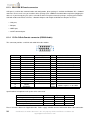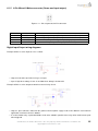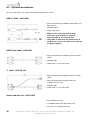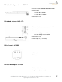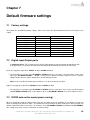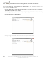
1
M AESTRO 100 3G
Q UICK S TART G UIDE & U SER M ANUAL
V ERSION 7
WWW. MAESTRO - WIRELESS . COM
E MAIL : CONTACT @ MAESTRO - WIRELESS . COM
T EL : (+852) 2869 0688
FAX : (+852) 2525 4701
A DDRESS : R OOM 3603-3609, 36/F, 118 C ONNAUGHT R OAD W EST, S HEUNG WAN , H ONG KONG
2
Confidential, the whole document is the sole property of Maestro Wireless Solutions ltd.
[email protected]
Revision history
Version
1
2
Date
29 Apr 2013
8 Jul 2013
3
4
5
30 Jul 2013
8 Aug 2013
28 Nov 2013
6
7
4 Dec 2013
13 Feb 2014
Details
First issue
Added power consumptions details.
Corrected typo in Chapter 5 Introduction and known issues.
Corrected product codes listing, typo.
Edited Digital Input/Output details.
Edited Know issues section.
Added label details.
Finalized temperature and humidity range.
Clarified packing details & DIO connection diagrams.
Corrected accessories details.
Added details on antenna positioning with GPS
Corrected item codes
Originated by
Samuel Chéreau
Samuel Chéreau
Samuel Chéreau
Samuel Chéreau
Samuel Chéreau
Samuel Chéreau
Samuel Chéreau
This manual is written without any warranty.
Maestro Wireless Solutions Ltd. reserves the right to modify or improve the product and its accessories which can
also be withdrawn without prior notice.
Besides, our company stresses the fact that the performance of the product as well as accessories depends not only
on the proper conditions of use, but also on the environment around the places of use.
Maestro Wireless Solutions Ltd. assumes no liability for damage incurred directly or indirectly from errors, omissions or discrepancies between the modem and the manual.
This software, solution or application is provided on an "as is" basis. No warranty whether expressed or implied is
given by Maestro Wireless Solutions Ltd. in relation to this software, solution or application. User shall assume
the entire risk of using or relying on this software, solution or application.
In no event will Maestro Wireless Solutions Ltd. be liable for any loss or damage including without limitation,
indirect or consequential loss, damage, or any loss, damage whatsoever arising from loss of data or profit arising out
of, or in connection with, the use of this software, application or solution.
Every effort is made to keep the software, application or solution up and running smoothly. However, Maestro
Wireless Solutions Ltd. takes no responsibility for, and will not be liable for, the software, application or solution
being temporarily unavailable due to technical issues beyond our control.
The above terms and conditions are subject to change without prior notice. The present use of this software, application or solution implies the user approves and understands all the above terms and conditions.
Confidential, the whole document is the sole property of Maestro Wireless Solutions ltd.
[email protected]
3
4
Confidential, the whole document is the sole property of Maestro Wireless Solutions ltd.
[email protected]
Contents
1 Known issues
9
2 Specifications
11
3 Related documents
13
4 Hardware installation
15
4.1 Mounting the modem . . . . . . . . . . . . . . . . . . . . . . . . . . . . . . . . . . . . . . . . . . . . . .
15
4.2 Installing the SIM card . . . . . . . . . . . . . . . . . . . . . . . . . . . . . . . . . . . . . . . . . . . . .
15
4.3 Connecting the external antennas (SMA type) . . . . . . . . . . . . . . . . . . . . . . . . . . . . . . . .
15
4.4 Connecting the modem to external device . . . . . . . . . . . . . . . . . . . . . . . . . . . . . . . . . .
16
4.5 Connecting the DC power supply . . . . . . . . . . . . . . . . . . . . . . . . . . . . . . . . . . . . . . .
16
5 Maestro 100 3G easy setup guideline
19
5.1 Downloading the Maestro Configuration Software . . . . . . . . . . . . . . . . . . . . . . . . . . . . . .
19
5.2 Using the Maestro Configuration Software . . . . . . . . . . . . . . . . . . . . . . . . . . . . . . . . . .
19
6 Equipments description
23
6.1 Interfaces . . . . . . . . . . . . . . . . . . . . . . . . . . . . . . . . . . . . . . . . . . . . . . . . . . . .
23
6.1.1 Status indicator . . . . . . . . . . . . . . . . . . . . . . . . . . . . . . . . . . . . . . . . . . . . .
23
6.1.2 SMA female antenna connector
. . . . . . . . . . . . . . . . . . . . . . . . . . . . . . . . . . .
23
6.1.3 Mini USB B Female connector . . . . . . . . . . . . . . . . . . . . . . . . . . . . . . . . . . . .
24
6.1.4 15-Pin D-Sub Female connector (RS232/Audio) . . . . . . . . . . . . . . . . . . . . . . . . . .
24
6.1.5 4-Pin Micro-fit Molex connector (Power and input/output)
. . . . . . . . . . . . . . . . . . . . .
25
6.2 Optional accessories . . . . . . . . . . . . . . . . . . . . . . . . . . . . . . . . . . . . . . . . . . . . . .
26
7 Default firmware settings
29
7.1 Factory settings . . . . . . . . . . . . . . . . . . . . . . . . . . . . . . . . . . . . . . . . . . . . . . . . .
29
7.2 Digital Input/Output ports . . . . . . . . . . . . . . . . . . . . . . . . . . . . . . . . . . . . . . . . . . .
29
7.3 RS232 auto-online mode (power saving)
29
. . . . . . . . . . . . . . . . . . . . . . . . . . . . . . . . . .
8 Troubleshooting
31
8.1 The modem’s LED does not light . . . . . . . . . . . . . . . . . . . . . . . . . . . . . . . . . . . . . . .
31
8.2 The modem’s LED lights but does not blink long time after power up . . . . . . . . . . . . . . . . . . .
31
8.3 The modem does not respond to the terminal program
31
. . . . . . . . . . . . . . . . . . . . . . . . . .
Confidential, the whole document is the sole property of Maestro Wireless Solutions ltd.
[email protected]
5
8.4 No voice could be heard for the modem’s speaker output when a call is answered
. . . . . . . . . . .
31
. . . . . . . . . . . . . . . . . . . . . .
32
8.6 Basic operations . . . . . . . . . . . . . . . . . . . . . . . . . . . . . . . . . . . . . . . . . . . . . . . .
33
8.7 Failsafe factory reinstall using USB Binary Update Tool . . . . . . . . . . . . . . . . . . . . . . . . . . .
33
8.5 Debug, or further command using Smart Terminal as example
6
Confidential, the whole document is the sole property of Maestro Wireless Solutions ltd.
[email protected]
Safety precautions
General precautions
– The modem generates radio frequency (RF) power. When using the modem care must be taken on safety
issues related to RF interference as well as regulations of RF equipment.
– Do not use the modem in aircraft, hospitals, petrol stations or in places where using GSM products is prohibited.
– Be sure that the modem will not be interfering with nearby equipment. For example: pacemakers or medical
equipment. The antenna of the modem should be away from computers, office equipment, home appliances,
etc...
– An external antenna must be connected to the modem for proper operation. Only used approved antennas with
the modem. Please contact authorized dealer on finding an approved antenna.
– Always keep the antenna with minimum safety distance of 26.6cm or more from human body.
– Do not put the antenna inside metallic box, containers, etc.
Using the modem in vehicle
– Check for any regulation or law authorizing the use of GSM in vehicle in your country before installing the
modem.
– Install the modem by qualified personnel. Consult your vehicle dealer for any possible interference of electronic
parts by the modem.
– The modem should be connected to the vehicle’s supply system by using a fuse-protected terminal in the
vehicle’s fuse box.
– Be careful when the modem is powered by the vehicle’s main battery. The battery may be drained after
extended period.
Protecting your modem
To ensure error-free usage, please install and operate your modem with care. Remember the following:
– Do not expose the modem to extreme conditions such as high humidity/temperatures, rain, direct sunlight,
caustic/harsh chemicals, dust, or water.
– Do not try to disassemble or modify the modem. There is no user serviceable part inside and the warranty
would be void.
– Do not drop, hit or shake the modem. Do not use the modem under extreme vibrating condition.
– Do not pull the antenna or power supply cable. Please attach or detach by holding the connector.
– Connect the modem only according to the instruction manual. Failure to do it will void the warranty.
Confidential, the whole document is the sole property of Maestro Wireless Solutions ltd.
[email protected]
7
8
Confidential, the whole document is the sole property of Maestro Wireless Solutions ltd.
[email protected]
Chapter 1
Known issues
Beware of the difference between M100 2G, M100evo and M100 3G GPIO type on the 4-pin Microfit connector.
M100 3G has two Digital Input/Output.
Below known issues on M100 3G:
1. Doesn’t support CSD call, updated firmware is R7.52 planed by Sierra Wireless for Q4 2013.
2. DCD, DSR, DTR signals are not currently available on the serial port, updated firmware is R7.53 planed by
Sierra Wireless for 2014.
Below known issues on M100 3G Engineering Samples:
1. For audio, when a call is initiated, you can hear the other party but the other party cannot hear you.
2. Supports only passive GPS antenna, final product support both passive and active GPS antenna.
3. Doesn’t support CSD call, updated firmware is R7.52 planed by Sierra Wireless for Q4 2013.
4. DCD, DSR, DTR signals are not currently available on the serial port, updated firmware is R7.53 planed by
Sierra Wireless for 2014.
Confidential, the whole document is the sole property of Maestro Wireless Solutions ltd.
[email protected]
9
10
Confidential, the whole document is the sole property of Maestro Wireless Solutions ltd.
[email protected]
Chapter 2
Specifications
– Quad bands GSM/GPRS/EDGE 850/900/1800/1900MHz
– M1003G SKU’s:
• M1003GXT00: WCDMA 850/1900MHz (SL8080T) with USB connector and GPS.
• M1003GXT02: WCDMA 900/2100MHz (SL8082T) with USB connector and GPS.
• M1003GXT04: WCDMA 800/850/2100MHz (SL8084T) with USB connector and GPS.
– Memory size: 64Mbits Flash and 16Mbits RAM
– Support Data, SMS, Voice and Fax
– SIM Tool Kit Class 2
– AT command set (GSM 07.05, GSM 07.07 and Sierra Wireless proprietary)
Power supply requirement:
– Input voltage range: 5-32V
– Rated current: 650mA
Typical current consumption:
Transmission WCDMA @ band 1, +23dBm
Transmission HSDPA @ band 1, +23dBm
Transmission EDGE @ +27dBm
Transmission GSM/GPRS @ +32dBm, 900MHz, 2 slots
Idle (RS232 & USB connected)
Idle (RS232 & USB not connected)
@5V
@12V
@32V
250mA
250mA
220mA
220mA
99mA
40mA
212mA
212mA
185mA
185mA
43mA
20mA
85mA
85mA
73mA
73mA
20mA
13mA
Interfaces:
– SIM Holder
– 15 pin sub-D connector
– 4 pin power supply connector
– SMA Cellular antenna connector (50Ω)
– mini-USB Female port
– SMA GPS antenna connector (50Ω)
Confidential, the whole document is the sole property of Maestro Wireless Solutions ltd.
[email protected]
11
Dimensions:
– Overall size: 74.3mm x 60mm x 21.7mm
– Weight: 90g
Temperature range:
– Operating: -40°C to +85°C with relative humidity below 95%
– Storage: -40°C to +85°C
CAUTION
In accordance with the European directive EN60590, if the ambient temperature exceeds or might exceed 65°C, it is
required that the installer:
- Avoid physical contact with the Maestro 100 3G when the temperature exceeds 65°C.
- Adds a marking on the assembly indicating that this part is hot (for example showing the “symbol IEC 60417-5041:
Caution, hot surface”; and/or having a wording similar to “CAUTION - HOT SURFACE - DO NOT TOUCH”).
Front label:
Back label, example of M1003GXT00:
Packing
– Bulk carton box of 50 pieces
– Each M100 3G in single plastic bag without any accessories
– Overall size: 522mm x 212mm x 150mm
– Weight: 4.3kg
12
Confidential, the whole document is the sole property of Maestro Wireless Solutions ltd.
[email protected]
Chapter 3
Related documents
This document presents technical and hardware specifications of the Maestro 100 3G industrial modem. It covers a
hardware installation, quick start guide, accessories listing, and troubleshooting details.
This document will not cover the embedded application details, neither the common 3GPP AT command list, for more
information please refer to the following documentations available on our website:
– SmartPack User Manual, intelligent embedded application
– Maestro 100 3G - AT command guide
– Application note - Automatic connections
– Application note - Power supply & Audio
– Application note - How to upgrade your modem in 5 steps
Please download related documents on http://www.maestro-wireless.com/m1003g
Confidential, the whole document is the sole property of Maestro Wireless Solutions ltd.
[email protected]
13
14
Confidential, the whole document is the sole property of Maestro Wireless Solutions ltd.
[email protected]
Chapter 4
Hardware installation
4.1
Mounting the modem
If delivered with the DIN clip accessory, detailed on page 27, use two M3 screws to mount the DIN clip on the back
of the modem as shown on figure 4.1.1.
Figure 4.1.1: DIN clip mounted on M100 3G
4.2
Installing the SIM card
Use a ball pen or paper clip to eject the SIM holder by pressing the eject button. Put the SIM card to the tray; make
sure it is completely inserted in the tray, then carefully put back the tray into the slot.
Note: DO NOT pull out the SIM holder without pushing the ejector button.
4.3
Connecting the external antennas (SMA type)
Connect both antennas with SMA male connector on the modem, make sure antennas are tightly secured. Select a
GSM antenna with the right GSM frequency and an impedance of 50Ω; incorrect antenna will affect communication
and even damage the modem. Select a GPS antenna with an impedance of 50Ω; incorrect antenna will affect GPS
sensitivity and time to fix.
Note: Make sure to install GSM and GPS antennas with an angle of at least 90º to avoid disturbance.
Refer to the drawing on Figure 4.3.1 on the following page.
Confidential, the whole document is the sole property of Maestro Wireless Solutions ltd.
[email protected]
15
Figure 4.3.1: Antenna position
Note: Respect a safety distance of at least 26.6cm to the antenna during the modem operation.
4.4
Connecting the modem to external device
Use Maestro standard DB15 to DB9 straight cable, detailed on page 26, or a common USB to mini-USB cable, to
connect an external controller or a computer. Refer to section 6.2 for more details on some other cable option or
adapter.
Note: If the Maestro 100 3G is connected with another DCE device please use a cross cable.
4.5
Connecting the DC power supply
If delivered with the power cord accessory, detailed on page 26, use the open ending of the power cord to connect a
DC supply. Refer to the following for power supply requirement:
– Input voltage range: 5-32V
– Rated current: 650mA
Figure 4.5.1: Power cord not included in the package
16
Confidential, the whole document is the sole property of Maestro Wireless Solutions ltd.
[email protected]
Plug the DC Molex connector of the power cord in the modem and it will turn on automatically. The status indicator
led will light when power is applied. After few seconds it will blink slowly, meaning the modem is registered on the
network.
Figure 4.5.2: Side view showing power and serial connector
Note: Modem can also be powered and connected by USB only using the ACC-CA41 Maestro ’X’
Cable as detailed in 6.2 on page 26.
Confidential, the whole document is the sole property of Maestro Wireless Solutions ltd.
[email protected]
17
18
Confidential, the whole document is the sole property of Maestro Wireless Solutions ltd.
[email protected]
Chapter 5
Maestro 100 3G easy setup guideline
The Maestro 100 3G of the M100 Series is the perfect solution for demanding M2M applications.
Ultra compact and fully-featured, the M100 3G can be integrated easily into any industrial machine from electricity
meters to intrusion alarms or vending machines. M100 3G modems are fully type approved, making them immediately usable worldwide. Boasting the reliability the M100 Series is known for, the M100 3G modems are the perfect
devices to use in any of your projects facing tough conditions or extended lifetime requirements. Fitted with a standard
fifteen pins RS232 port and Windows configuration tool the M100 3G can be set up with minimal effort.
All M100 3G also features two digital input/output pins. The M100 3G XT adds a mini-USB connector and GPS
feature.
Maestro 100 3G Series:
– M100 3G XT with USB and GPS.
– M100 3G Tracker: supporting tracking application for GPS based alert report (Q2 2014).
5.1
Downloading the Maestro Configuration Software
Start the web browser of your choice and download the Maestro Configuration Software at this address:
http://www.maestro-wireless.com/configuration-software/.
Please start the setup.exe application and follow instructions shown on screen. It will also create a shortcut on your
desktop.
5.2
Using the Maestro Configuration Software
The window shown on Figure 5.2.1 on the following page will appear when the application starts, you need to enter
your COM port settings and click “Connect” button. Default settings are 115200, 8 data 1 stop, parity none, detailed
on page 29. The serial configuration settings will be saved upon connection.
Details of Figure 5.2.1:
1. Com port: select the correct COM port to use. The box will auto-refresh on click. Selected COM port will be
saved after connection.
2. Serial configuration: select the correct settings for the serial port, and click “Connect”. Settings will be saved
on connection. If modem reply to AT+VAFV command it will automatically switch the window to the “Modem
Status” page and if it only reply to AT command the window will switch to “Terminal” page.
3. Update your modem: use this tool to upgrade your modem, that handle both firmware and latest Maestro
application.
4. Diagnostics to contact support: as stated please use this button to generate a report of all common AT
command that will help us solve any issue you have with the modem easily.
5. Auto-detect serial configuration: will detect your modem serial configuration automatically, though it may
take some time.
Confidential, the whole document is the sole property of Maestro Wireless Solutions ltd.
[email protected]
19
Figure 5.2.1: Start page - Maestro Configuration Software
6. Menu tab page: once connected menu will show ready for use and could do configuration of all modem
features.
7. Quick connect/disconnect button.
8. AT command sent status message: will show the current AT command sent to the modem for a quick debug.
9. Quick signal strength overview which can be deactivated.
Figure 5.2.2: Status page - Maestro Configuration Software
Once connected, the interface will switch to the “Modem Status” page, see Figure 5.2.2, displays the reception signal
strength (RSSI, refreshed every five seconds), your SIM card network name, as well as the revision number for the
embedded application and firmware.
20
Confidential, the whole document is the sole property of Maestro Wireless Solutions ltd.
[email protected]
The Maestro Configuration Software add an easy to configure interface to all the SmartPack features, detailed as:
– Data & Serial to IP socket: AutoTCP/UDP, IP packet settings, ...
– Call Screening,
– Remote control: both SMS and TCPTerminal, and Dynamic DNS,
– TMODE,
– DOTA,
– Input triggered AT command,
– SMS: for both reading and sending in Text mode, and AutoPIN,
– IP Ping,
– Command String scripting language,
– GPS for M100 3G XT (will be added by Q4 2013).
The last and not least page of the Maestro Configuration Software is the Terminal, which is a Windows HyperTerminal
replacement with log, quick command features, see Figure 5.2.3.
Figure 5.2.3: Terminal page - Maestro Configuration Software
Confidential, the whole document is the sole property of Maestro Wireless Solutions ltd.
[email protected]
21
22
Confidential, the whole document is the sole property of Maestro Wireless Solutions ltd.
[email protected]
Chapter 6
Equipments description
6.1
Interfaces
Above picture reflects real device dimensions.
6.1.1
Status indicator
The LED will indicate different status of the modem:
– OFF: modem is switched off,
– ON: modem has no network and GPS doesn’t have a fix,
– ON, and OFF pulse every 10 second: modem has no network and GPS has a fix,
– Flashing slowly: modem is registered on the network and GPS doesn’t have a fix,
– Flashing rapidly: modem is registered on the network and GPS has a fix.
6.1.2
SMA female antenna connector
– GSM SMA female connector: fits penta band 850/900/1800/1900/2100MHz antenna with impendance of 50Ω,
– GPS SMA female connector: fits active or passive GPS antenna with impedance of 50Ω.
Note: Make sure to install GSM and GPS antennas with an angle of at least 90º to avoid disturbance.
a Important note the Engineering Sample support only passive GPS antenna a
Confidential, the whole document is the sole property of Maestro Wireless Solutions ltd.
[email protected]
23
6.1.3
Mini USB B Female connector
USB port is used for data communication and configuration, driver package is available for Windows XP, 7, Android
and Linux. Please make sure you install the driver package (File: USBDriv erInstallerV3841.exe) before plugging the
device in. If you already plug it in, please reinstall the driver using those from the package, and plug your unit back.
USB will enable and emulate a Device, a Network Adapter and multiple COM Port on computer to access:
– CNS port,
– DM port,
– NMEA port,
– and AT command port.
6.1.4
15-Pin D-Sub Female connector (RS232/Audio)
This connector provides serial link and audio link to the modem.
Pin Number
Name
EIA designation
Type
1
2
3
4
5
6
7
8
9
10
11
12
13
N/A
TxD
NC
MICROPHONE +
MICROPHONE RxD
N/A
N/A
GND
SPEAKER +
CTS
RTS
RI
Data Carrier Detect
Transmit Data
Input
14
RESET
Input
15
SPEAKER -
Output
Receive Data
Data Set Ready
Data Terminal Ready
Ground
Clear To Send
Request To Send
Ring Indicator
Note
available with R7.53 firmware
Input
Input
Output
With 2VDC bias output
With 2VDC bias output
available with R7.53 firmware
available with R7.53 firmware
Ground
Output
Output
Input
Output
Pull low for 100ms to reset,
module require 5-7s to reboot
Specification of microphone and speaker to be connected:
Parameters
Microphone current @ 2V/2kΩ
Microphone input level
Speaker output current 150Ω/1nF
Speaker impedance
Min
Typical
Max
0.5mA
100mVpp
32Ω
16mA
50Ω
Please refer to the document "Application note - Power supply & Audio" for more information about audio connection.
24
Confidential, the whole document is the sole property of Maestro Wireless Solutions ltd.
[email protected]
6.1.5
4-Pin Micro-fit Molex connector (Power and input/output)
Figure 6.1.1: Pin assignment of 4-Pin connector
Pin number
Name
Functions
1
2
3
4
DIO1
DIO2
POWER POWER +
Digital Input/Output (3V for input detection, 12V max.)
Digital Input/Output (3V for input detection, 12V max.)
DC power negative input (or ground)
DC power positive input (5V to 32V max.)
Digital Input/Output wiring diagrams
Example of DIO1 used as input to sense a switch:
– Output needs to be open when using as an input.
– Input is high when voltage is over 3V and low when voltage is below 0.5V.
Example of DIO1 used as output to control an external relay circuit:
– Output is open collector, shorted to the ground, external power supply needs to be added in current driven
application, maximum current is 200mA.
– If used to control relay, a protection diode needs to be added in parallel of the relay coil to avoid current peak
when triggered.
Confidential, the whole document is the sole property of Maestro Wireless Solutions ltd.
[email protected]
25
6.2
Optional accessories
You may contact your sales agent for the following optional accessories:
USB ’X’ Cable - ACC-CA41
– Direct connection with standard USB for power and
data channels
– Shielded cabled
– Cable length 50cm
– Make sure the current given to the USB
connectors from computer is sufficient,
especially while in 3G communication
– Using USB ’X’ Cable may alter performance of
the M100 3G if used in very poor area or with too
low power supplied
DB15 Serial cable - ACC-CA01
– Direct connection with standard 9-pin RS-232 port
(DTE)
– Shielded cable
– Cable length 1.1m (w/ connector)
’Y’ cable - ACC-CA14A
– Direct connection with standard 9-pin RS-232 port
(DTE)
– Direct connection with common handset of
telephone for voice call
– Shielded cable
– Cable length 1.1m (w/ connector)
Power cord with fuse - ACC-CA10
– 4-pin Microfit connector
– 1m AWG20 cables with stripped wire end
– 2.5A glass fuse with plastic holder
26
Confidential, the whole document is the sole property of Maestro Wireless Solutions ltd.
[email protected]
Penta-band L-shape antenna - ACC-A11
– Frequency bands: 850/900/1800/1900/2100MHz
– Antenna Gain
• 2.0 ± 0.7dBi @ 880MHz
• 1.0 ± 0.7dBi @ 1990MHz
– Polarization Linear
Penta-band antenna - ACC-A17A
– Frequency bands: 850/900/1800/1900/2100MHz
– Gain +1dBi
– Antenna Gain
• 1.0 ± 0.7 dBi @ 824~960MHz
• 0.5 ± 0.7 dBi @ 1710~2170MHz
– Polarization Linear
– Cable length 1m (w/ connector)
DIN rail mount - ACC-DIN
– SPCC steel
– Thickness: 1.2mm
DB15 to DB9 adapter - OTH-004
– Plastic molded with screws
– Length: 36mm (w/ connector)
Confidential, the whole document is the sole property of Maestro Wireless Solutions ltd.
[email protected]
27
28
Confidential, the whole document is the sole property of Maestro Wireless Solutions ltd.
[email protected]
Chapter 7
Default firmware settings
7.1
Factory settings
The modem has the following factory settings. Please refer to the AT command document for the meaning of each
setting.
7.2
Related AT commands
Factory settings
Description
AT+IPR
AT+IFC
AT+ICF
ATE
ATQ
ATV
ATS0
AT+CSCS
AT+CMGF
115200
2,2
3,4
1
0
1
0
“PCCP437”
1
DTE-DCE data rate
DTE-DCE flow control
DTE-DCE character framing
ECHO
Result code suppression
Response format
Auto answer
Character Set
Short message format
Digital Input/Output ports
/!\ Important notice: This section concern only OpenAT developer that will need to control GPIOs from
their application, else the Maestro SmartPack will control GPIOs through SmartPack AT commands.
Inputs are mapped in OpenAT to: GPIO01 for DIO1, GPIO03 for DIO2.
– To setup DIO1 as an input, type AT+WIOM=1,"GPIO01",0 on the serial port. Then to read the status of the
input, type AT+WIOR="GPIO01". +WIOR: 1 means input is below 0.5V while +WIOR: 0 means a positive
voltage of more than 3V. Higher voltage than 12V will damage the unit.
Note: Please note that the output port need to be set as open for the input to work.
Outputs are mapped in OpenAT to: GPIO06 for DIO1, GPIO05 for DIO2.
– To setup DIO1 as an output, type AT+WIOM=1,"GPIO06",1 on the serial port. Then set the state of the output
with AT+WIOW="GPIO06",0 to set the output as open, or AT+WIOW="GPIO06",1 to set the output as close.
7.3
RS232 auto-online mode (power saving)
When on auto-online mode, the RS232 transceiver will shut down most of its hardware, to save power, if it does not
detect a valid input for more than 100µs. The RS232 transceiver will wake up when valid input is detected again. By
default, auto-online mode is not active. To activate it, issue AT+WIOM=1,”GPIO02”,1,0 followed by AT+WIOM=4.
This setting needs to be set once, and will be saved in memory.
Confidential, the whole document is the sole property of Maestro Wireless Solutions ltd.
[email protected]
29
30
Confidential, the whole document is the sole property of Maestro Wireless Solutions ltd.
[email protected]
Chapter 8
Troubleshooting
8.1
The modem’s LED does not light
– Check if the modem has been properly connected to a 5-32V power supply
– Check if the power connector is properly inserted
– Check the fuse in the power cord
8.2
The modem’s LED lights but does not blink long time after power up
– Check if a valid SIM card has been properly inserted
– Check if the SIM card has been locked (refer to AT+CPIN command in AT command guide)
– Check if the external power has been properly connected to the modem
– Check if the network coverage is available
– Make sure that the CTS and DTR pins of the serial port are not connected together
8.3
The modem does not respond to the terminal program
– Check if the RS232 cable has been properly connected
– Check if your program has proper settings. Factory setting of the modem is:
• 115200 bps
• 8 data bits
• No parity bit
• 1 stop bit
8.4
No voice could be heard for the modem’s speaker output when a call
is answered
– Make sure a voice call has been made (refer to AT command guide)
– Enter the AR+SPEAKER=2 command
Confidential, the whole document is the sole property of Maestro Wireless Solutions ltd.
[email protected]
31
8.5
Debug, or further command using Smart Terminal as example
First, you can find our Hyper Terminal substitute at the following address: http://www.maestro-wireless.com/
smart-terminal. Then follow the steps:
– Open the software, you can find the shortcut on your desktop, or access it by the Start menu > All Programs >
Maestro Wireless Solutions > Smart Terminal.
– Once open you will have to select the good serial port configuration (By default: COM1, 115200, 8 data 1 stop,
none, with hardware flow control)
– Open the port by ticking the Port opened box :
– Then you can type command like “AT” and check the "OK" response from the modem.
32
Confidential, the whole document is the sole property of Maestro Wireless Solutions ltd.
[email protected]
8.6
Basic operations
Followings are examples of some AT commands. Please refer to the AT command document for a full description.
Note: Issue AT+CMEE=1 to have extended error code (+CME ERROR)
Description
AT commands
Modem response
Network
registration
checking
AT+CREG?
CREG=<mode>,1
Modem registered to the network
CREG=<mode>,2
Registration lost, re-registration attempt
Modem not registered on the network, no
registration attempt
The first parameter has to be at least 15 for
normal communication
CREG=<mode>,0
Receiving signal
strength
Receiving an
incoming call
Make a call
AT+CSQ
+CSQ:20,0
RING
An incoming call is waiting
ATA
OK
ATD1234567;
OK
Answer the call
Communication established (Don’t forget the
“;” at the end for “voice” call)
PIN code not entered (with +CME=1 mode)
AOC credit exceeded or a communication is
already established
Communication established (Don’t forget the
“;” at the end for “voice” call)
+CME ERROR: 11
+CME ERROR: 3
Make an
emergency call
Communication
loss
Hang up
Enter PIN code
Saves parameters
in non-volatile
memory
8.7
Comments
ATD 112;
OK
NO CARRIER
ATH
AT+CPIN=1234
OK
OK
+CME ERROR: 16
+CME ERROR: 3
PIN Code accepted
Incorrect PIN code (with +CME=1 mode)
PIN already entered (with +CME=1 mode)
AT&W
OK
The configuration settings are stored
Failsafe factory reinstall using USB Binary Update Tool
In case your modem firmware is crash or can’t be flash via Serial port, Maestro Wireless can provide a binary update
tool using USB, please contact [email protected] to receive those files.
Confidential, the whole document is the sole property of Maestro Wireless Solutions ltd.
[email protected]
33