1
R911305038 / 01 | Rexroth VCP-Operating Concept
Electric Drives and Controls | Bosch Rexroth AG
6-93
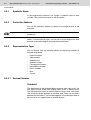
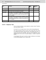
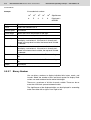
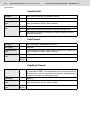
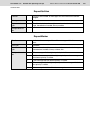
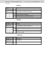
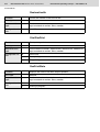
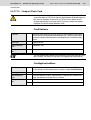
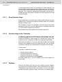
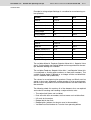
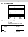
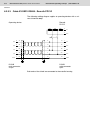
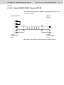
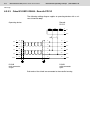
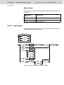
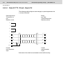
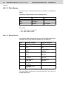
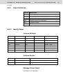
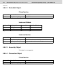
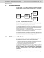
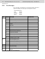
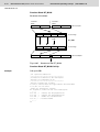
DIN Measurement Bus
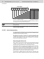
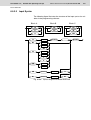
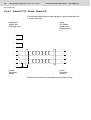
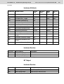
Request from PLC
Response from gateway
High byte
15
8
Byte y
Trigger byte
1
Low byte
14
7
0
Return value
Byte y+1
Function mark
Byte y+3
Data 1
Byte y+5
Data 3
Byte y+7
Data 5
Byte y+9
Data 7
Byte y+11
Data 9
Byte y+13
Reserved
Byte y+15
Word x
1
Slave number
Byte y+2
Data 0
Byte y+4
Data 2
Byte y+6
Data 4
Byte y+8
Data 6
Byte y+10
Data 8
Byte y+12
Data 10
Byte y+14
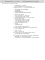
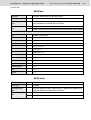
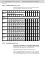
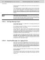
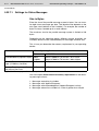
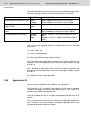
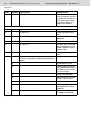
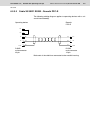
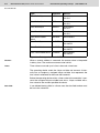
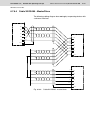
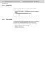
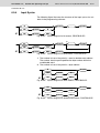
Fig. 6-143:
Word x+1
Word x+2
Word x+3
Word x+4
Word x+5
Word x+6
Word x+7
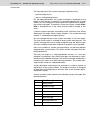
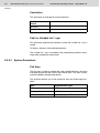
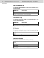
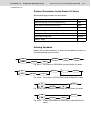
Structure of poll area for DIN Measurement Bus
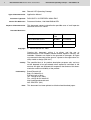
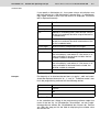
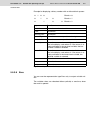
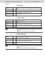
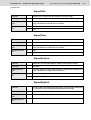
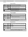
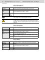
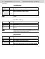
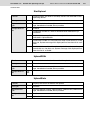
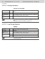
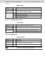
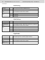
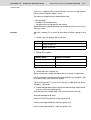
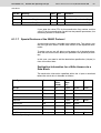
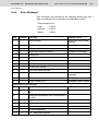
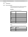
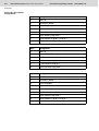
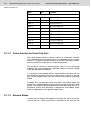
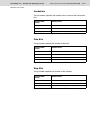
Byte
Bit
Function
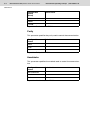
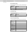
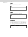
Slave Number
0
Data are intended for the gateway itself
1 to 31
Slave number to which the event is
transmitted by order-only
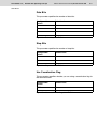
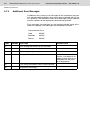
1
Transfer new Write co-ordination byte
2
Transmit message
3
Activate/deactivate LEDs
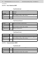
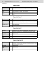
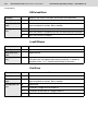
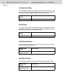
0
Ok-acknowledge signal
1
Slave is not ready to receive
2
General DIN Measurement Bus error
3
Invalid function code
4
Slave not synchronized
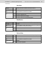
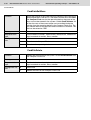
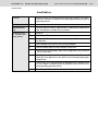
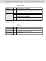
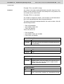
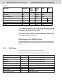
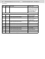
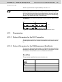
Function Code
Return Value
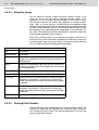
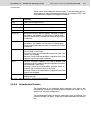
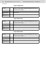
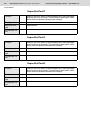
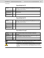
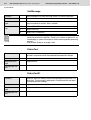
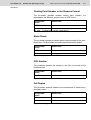
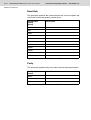
Function "Transmit new Write coordination byte (WCB)"
Data 0
WCB (Write coordination byte)
Data 1
Available
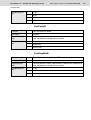
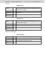
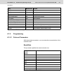
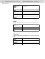
Function "Transmit message"
Data 0
Message number high byte
Data 1
Message number low byte
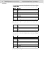
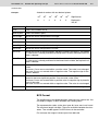
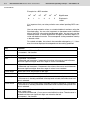
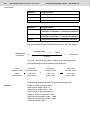
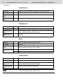
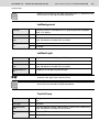
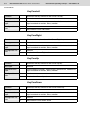
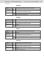
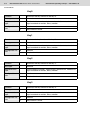
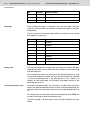
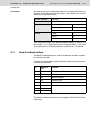
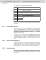
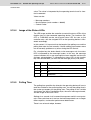
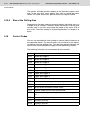
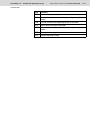
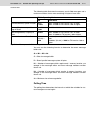
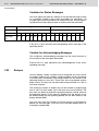
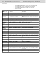
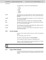
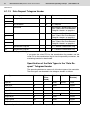
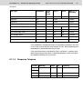
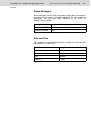
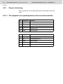
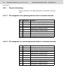
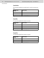
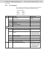
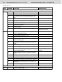
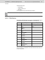
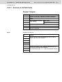
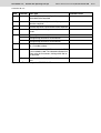
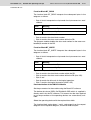
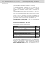
Fig. 6-144:
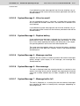
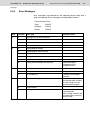
Function of the individual bytes