1
5 Installation (continued)
4
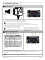
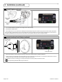
Install BodyGuard
RED
BLACK
WHITE
GREEEN
BodyGuard Cable
Route to
‘BG’
BROWN
BLUE
1 PWR
2 PWR
3 COM
4 NO
5 NC
6 IN 7 IN +
10 PIN
BodyGuard
10 PIN
1. For complete installation instructions refer to BodyGuard User’s Guide (75.5134).
NOTE: BEA recommends the use of the Bodymount during all Bodyguard installations.
NOTE: On a single door installation the Bodyguard should be angled to 10 degrees (5 degrees default).
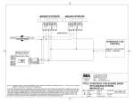
2. Plug ten pin connector into BodyGuard as shown above (hard wire as shown above only if ten pin connector is not available).
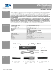
3. Route BodyGuard Cable Harness (20.5082) through door header to DP-Hub.
4. Plug BodyGuard Cable into DP-Hub at location labeled ‘BG’.
NOTE: For dual egress use Y-harness for second BodyGuard.
NOTE: For independent dual egrees, two DP-Hubs are required.
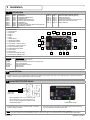
5
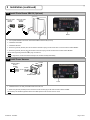
NOTE: BodyGuard Jumper (BodyGuard plug with orange
jumper wire) can be used to setup the system when the
BodyGuard is on the door header cover. It can also be used
in low energy applications.
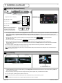
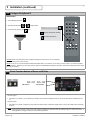
Install Door Control Harness(s)
The DP-Hub provides two door control outputs for door
controls that cannot be paralleled together.
WIRE
OUTPUT
Green
Activation NO
Yellow
Activation NC
‘TYPICAL’ DOOR
CONTROL
White
Activation COM
COM
Safety NO
SAFETY
Yellow/Black
Safety NC
White/Black
Safety COM
COM
STALL
Green/Red
Stall NO
Stall NC
White/Red
Stall COM
Door
Control 2
ACTIVATION
Green/Black
Yellow/Red
Door
Control 1
STALL COM
For a list of specific door control connections please refer to
Appendix B.
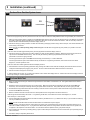
1. Make connections to the door control(s) as displayed above.
2. Route wiring harness(s) (20.5222) from door control to DP-Hub and plug into DP-Hub at location marked ‘CONTROL 1’ and/or
‘CONTROL 2’.
NOTE: Typically on the door control, the common (COM) for the Stall input is isolated from the common for Activation and Safety. If the door control
has one common input, tie all the common outputs from the DP-Hub together.
75.5652.03 20130617
Page 3 of 16