1
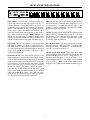
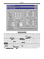
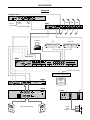
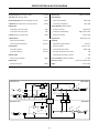
FRONT & REAR PANEL FEATURES
input
input
input
input
input
d. out
input
d. out
input
d. out
input
d. out
aux 1
d. out
aux 2
d. out
aux
d. out
main
serial port
d. out
out
logic outputs
in
~
27V
50/60 Hz
27 watts
class 2 wiring
link port
link
logic inputs
expansion
outputs
auxiliary inputs
channel 8
channel 7
channel 6
channel 5
channel 4
channel 3
channel 2
channel 1
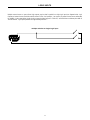
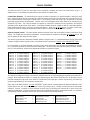
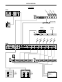
Logic Outputs: This 9-pin Sub-D connector provides Logic
Outputs from Channels 1~8 (see Logic Outputs on pg. 12). If a
channel is assigned as ‘auto’ to either Main Out or Aux Out, the
corresponding Logic Output will turn on whenever the channel is
gated on. Logic Outputs may be used to control external switching
®
circuits, such as relays or other ADVANTAGE products. These
outputs are typically used to turn off speakers or select cameras
when certain microphones are active. NOTE: Individual Logic
Outputs may be turned on/off via software or remote control.
However, this temporarily defeats their ability to follow the active
channel, until again assigned to ‘follow gate’ (see Setup on pg. 5).
Main Out: This plug-in barrier strip provides the balanced Main
Out from the VRAM. For balanced output, wire high to (+), low to
(-), and ground to ( ). For unbalanced output, wire high to (+) and
ground to ( ), leaving (-) unconnected. Signal level will be reduced
by 6dB when outputs are unbalanced.
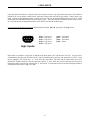
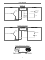
Logic Inputs: This 9-pin Sub-D (female) connector provides eight
logic inputs for controlling the VRAM via contact-closures (see
Logic Inputs on pg. 10). Logic Inputs are programmed using the
PC Control Software and serial cable provided with the VRAM (see
Setup on pg. 8). NOTE: From the factory, Logic Inputs 1~8 have
no pre-programmed function.
Aux 1 & Aux 2 Inputs: These plug-in barrier strips provide the
balanced auxiliary line inputs to the VRAM. For balanced input,
wire high to (+), low to (-), and ground to ( ). For unbalanced input,
wire high to (+) and ground to both (-) & ( ).
ý
ý
Aux Out: This plug-in barrier strip provides the balanced Aux Out
from the VRAM. For balanced output, wire high to (+), low to (-),
and ground to ( ). For unbalanced output, wire high to (+) and
ground to ( ), leaving (-) unconnected. Signal level will be reduced
by 6dB when outputs are unbalanced.
ý
ý
ý
ý
Channel Input & Direct Output: These plug-in barrier strips
provide the balanced mic/line input to the respective channels. For
balanced input, wire high to (+), low to (-), and ground to ( ). For
unbalanced input, wire high to (+) and ground to both (-) & ( ).
Unbalanced Direct Outputs are also available from the channels
using (d out) & ( ). NOTE: Inputs & Direct Outputs can be
assigned for ‘auto’ (gated) or on/off operation (see Setup on pg. 5).
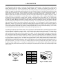
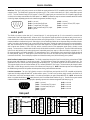
Expansion In & Out: These 6-pin mini-DIN connectors are for
linking multiple mixers, to increase the number of input channels.
A 6-pin mini-DIN cable is provided with each mixer. To link mixers,
simply connect the cable from the Expansion Out jack of one mixer
to the Expansion In jack of the next mixer (and so forth). The final
mixer in the system (with no Expansion Out jack connection)
becomes the ‘master’. The ‘master’ collects audio signals &
control data from the other mixers, which become ‘slaves’. Main
Out & Aux Out signals, plus NOM attenuation, for the combined
system are provided by the ‘master’. The outputs from ‘slave’
mixers provide only signals from their own inputs, plus those of
any ‘slave’ mixers connected to them via Expansion In.
ý
ý
ý
3