1
SETUP
®
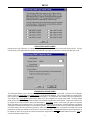
VRAM & VRAMeq parameters are all adjustable using the Windows 95/98/NT ’PC Control Software’ and serial cable provided with the
®
unit. The PC Control Software provides programs for various ADVANTAGE products, including the VRAM(eq). The VRAM program
includes seven control screens, which are described on the following pages. Once the software is started (and Comm Port Configuration is
set), the control screens are accessed via the drop-down menus at the top of the opening screen. The Mix screen appears whenever a
VRAM file is opened. Channel Settings, Automixer Settings, Button Definitions, Logic Input Definitions, Logic Output Polarity, &
Configuration Options screens are then available from the Configure VRAM menu. The File menu provides functions such as save, open,
download, etc. The Settings menu recalls the Comm Port Configuration screen. The Window menu arranges the active product screens.
The Help menu explains the available adjustments. To install PC Control Software: Select ‘Run’ from the ‘Start’ menu, and enter
®
A:\SETUP. System Requirements: Windows 95/98/NT with 16M RAM & 5M of available hard disk space (serial port required for ‘on-line’
operation).
MIX SCREEN
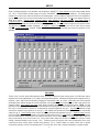
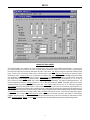
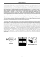
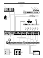
The Mix Screen is used to adjust VRAM input/output levels, as well as to store/recall sixteen memory presets. All VRAM inputs may be
adjusted to each output independently. Each output is also independently adjusted. Adjustments are made with the computer mouse (or
keyboard). Input & output levels are adjusted by dragging the corresponding ‘faders’ up or down. Mute buttons turn off the respective
input/output signals, without changing the channel assignments (see next page). Mix Bus meters display ‘pre-fader’ signal levels for the
respective outputs. Main Output & Aux Output meters display ‘post-fader’ signal levels for the respective outputs. NOTE: For best
performance, adjust faders so the meters show occasional peaks in the yellow area, but never to the top (red). Peak indicators should
flash only on occasional peaks in signal level, as determined by input gain adjustments (see pg. 5). Logic Outputs indicators will light
whenever the respective Logic Outputs are on (see pg. 5). Gate indicators will light whenever channels are active to the corresponding
outputs (see pg. 5). Channel Settings selects a screen for adjusting individual input parameters (see pg. 5). Automixer Settings selects a
screen for adjusting automatic mixing functions, which affect the entire mixer (see pg. 6). Preset buttons recall the corresponding presets
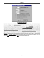
from non-volatile memory. Presets must first be created & stored by the user (no factory presets). The Store button opens a menu for
storing current settings in any of the Presets 1~16. Each preset includes settings from the Mix screen, as well as from the Channel
Settings & Automixer Settings screens (see pgs. 5 & 6). The title bar across the top of the Main screen will indicate the Device #, the
custom Device Name, and the model of product being controlled. The PC Control Software can operate ‘off-line’ (with no product
connected) by opening a ‘new’ file for the desired product. The Device # for ‘off-line’ files is assigned sequentially as a negative number.
4