1
Dialogic® System Release 6.0 PCI
for Windows®
Release Update
January 30, 2008
05-2221-062
Copyright © 2004-2008, Dialogic Corporation. All Rights Reserved. You may not reproduce this document in whole or in part without permission in
writing from Dialogic Corporation at the address provided below.
All contents of this document are subject to change without notice and do not represent a commitment on the part of Dialogic Corporation or its
subsidiaries. Reasonable effort is made to ensure the accuracy of the information contained in the document. However, due to ongoing product
improvements and revisions, Dialogic Corporation and its subsidiaries do not warrant the accuracy of this information and cannot accept responsibility
for errors or omissions that may be contained in this document.
INFORMATION IN THIS DOCUMENT IS PROVIDED IN CONNECTION WITH DIALOGIC® PRODUCTS. NO LICENSE, EXPRESS OR IMPLIED, BY
ESTOPPEL OR OTHERWISE, TO ANY INTELLECTUAL PROPERTY RIGHTS IS GRANTED BY THIS DOCUMENT. EXCEPT AS EXPLICITLY SET
FORTH BELOW OR AS PROVIDED IN A SIGNED AGREEMENT BETWEEN YOU AND DIALOGIC, DIALOGIC ASSUMES NO LIABILITY
WHATSOEVER, AND DIALOGIC DISCLAIMS ANY EXPRESS OR IMPLIED WARRANTY, RELATING TO SALE AND/OR USE OF DIALOGIC
PRODUCTS INCLUDING LIABILITY OR WARRANTIES RELATING TO FITNESS FOR A PARTICULAR PURPOSE, MERCHANTABILITY, OR
INFRINGEMENT OF ANY INTELLECTUAL PROPERTY RIGHT OF A THIRD PARTY.
Dialogic products are not intended for use in medical, life saving, life sustaining, critical control or safety systems, or in nuclear facility applications.
It is possible that the use or implementation of any one of the concepts, applications, or ideas described in this document, in marketing collateral
produced by or on web pages maintained by Dialogic Corporation or its subsidiaries may infringe one or more patents or other intellectual property
rights owned by third parties. Dialogic Corporation or its subsidiaries do not provide any intellectual property licenses with the sale of Dialogic products
other than a license to use such product in accordance with intellectual property owned or validly licensed by Dialogic Corporation or its subsidiaries.
More detailed information about such intellectual property is available from Dialogic Corporation's legal department at 9800 Cavendish Blvd., 5th
Floor, Montreal, Quebec, Canada H4M 2V9. The software referred to in this document is provided under a Software License Agreement. Refer to the
Software License Agreement for complete details governing the use of the software.
Dialogic Corporation encourages all users of its products to procure all necessary intellectual property licenses required to implement any
concepts or applications and does not condone or encourage any intellectual property infringement and disclaims any responsibility
related thereto. These intellectual property licenses may differ from country to country and it is the responsibility of those who develop the
concepts or applications to be aware of and comply with different national license requirements.
Dialogic, Dialogic Pro, Brooktrout, Cantata, SnowShore, Eicon, Eicon Networks, Eiconcard, Diva, SIPcontrol, Diva ISDN, TruFax, Realblocs,
Realcomm 100, NetAccess, Instant ISDN, TRXStream, Exnet, Exnet Connect, EXS, ExchangePlus VSE, Switchkit, N20, Powering The ServiceReady Network, Vantage, Connecting People to Information, Connecting to Growth, Making Innovation Thrive, and Shiva, among others as well as
related logos, are either registered trademarks or trademarks of Dialogic.
Microsoft, MSDN, Visual C++, Visual Studio, Windows, Windows Server and Windows Vista are registered trademarks of Microsoft Corporation in the
United States and/or other countries. Other trademarks mentioned in this document are the property of their respective owners.
Publication Date: January 30, 2008
Document Number: 05-2221-062
Dialogic® System Release 6.0 PCI for Windows® Release Update, Rev 62 – January 30, 2008
About This Publication
This section contains information about the following topics:
• Purpose
• Intended Audience
• How to Use This Publication
• Related Information
Purpose
This Release Update addresses issues associated with Dialogic® System Release 6.0
PCI for Windows® (sometimes also referred to herein as “System Release 6.0 PCI
Windows”). In addition to summarizing issues that were known as of the Release’s
general availability, it is intended that this Release Update will continue to be updated to
serve as the primary mechanism for communicating new issues, if any, that may arise
after the release date.
Intended Audience
This Release Update is intended for users of System Release 6.0 PCI Windows.
How to Use This Publication
This Release Update is organized into four sections (click the section name to jump to the
corresponding section):
• Document Revision History: This section summarizes the ongoing changes and
additions that are made to this Release Update after its original release. This section
is organized by document revision and document section.
• Post-Release Developments: This section describes significant changes to the
system release subsequent to the general availability release date. For example, the
new features provided in Service Updates are described here.
• Release Issues: This section lists issues that may affect the system release hardware
and software. The primary list is sorted by issue type, but alternate sorts by defect
number, by product or component, and by Service Update number are also provided.
• Documentation Updates: This section contains corrections and other changes that
apply to the System Release documentation set that were not made to the documents
prior to the release. The updates are organized by documentation category and by
individual document.
Dialogic® System Release 6.0 PCI for Windows® Release Update, Rev 62 — January 30, 2008
Dialogic Corporation
3
About This Publication
Related Information
See the following for additional information:
• For information about the products and features supported in this release, see the
Dialogic® System Release 6.0 PCI for Windows® Release Guide, which is included as
part of the documentation bookshelf for the release.
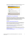
• For further information on issues that have an associated defect number, you may use
the Defect Tracking tool at http://membersresource.dialogic.com/defects/. When you
select this link, you will be asked to either LOGIN or JOIN.
• http://www.dialogic.com/support/ (for Dialogic technical support)
• http://www.dialogic.com/ (for Dialogic® product information)
Dialogic® System Release 6.0 PCI for Windows® Release Update, Rev 62 — January 30, 2008
Dialogic Corporation
4
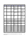
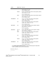
Document Revision History
This Revision History summarizes the changes made in each published version of the
Release Update for Dialogic® System Release 6.0 PCI for Windows®, which is a
document that has been and is intended to be periodically updated throughout the lifetime
of the release.
Document Rev 62 - published January 30, 2008
Updated for Service Update 181.
In the Post-Release Developments section:
• Added Runtime Control of Single or Double Hookflash on Consultation Drop for
FXS/LS Protocol.
• Deleted the detailed descriptions about some Dialogic® Global Call SS7 features that
were previously included in this section, because this information has been
incorporated into the updated Dialogic® Global Call SS7 Technology Guide that is
now on the online documentation bookshelf.
In the Release Issues section, added the following resolved problems: IPY00040874,
IPY00041079, IPY00041421, IPY00041426.
In the Documentation Updates section:
• Added documentation update to the Dialogic® Global Call E1/T1 CAS/R2 Technology
Guide because of a new feature in the Service Update.
• Deleted the corrections for the Dialogic® Global Call SS7 Technology Guide, because
these corrections have been incorporated into an updated document that is now on
the online documentation bookshelf.
• Added documentation update to the Dialogic® Voice API Library Reference for the
dx_getdig( ) function (IPY00038453).
• Deleted the sections for the Dialogic® Conferencing (CNF) API Library Reference and
Dialogic® Conferencing (CNF) API Programming Guide. These documents have been
removed from the online documentation bookshelf because the CNF API is no longer
supported in Dialogic® System Release 6.0 PCI for Windows®.
Document Rev 61 - published December 28, 2007
Updated for Service Update 178.
In the Release Issues section, added the following resolved problems: IPY00039334,
IPY00040536, IPY00041078, IPY00041082, IPY00041178, IPY00041209, IPY00041233,
IPY00041345.
Dialogic® System Release 6.0 PCI for Windows® Release Update, Rev 62 — January 30, 2008
Dialogic Corporation
5
Document Revision History
In the Documentation Updates section:
• Deleted the corrections for the Dialogic® Audio Conferencing API Library Reference
and Dialogic® Audio Conferencing API Programming Guide, because these
corrections have been incorporated into updated documents that are now on the
online documentation bookshelf.
• Deleted some of the corrections for the Dialogic® Continuous Speech Processing API
Library Reference and Dialogic® Continuous Speech Processing API Programming
Guide, because these corrections have been incorporated into updated documents
that are now on the online documentation bookshelf.
• Deleted the corrections for the Dialogic® Standard Runtime Library API Library
Reference and Dialogic® Standard Runtime Library API Programming Guide,
because these corrections have been incorporated into updated documents that are
now on the online documentation bookshelf.
Document Rev 60 - published November 15, 2007
Updated for Service Update 174.
In the Post-Release Developments section:
• Added Analog Call Transfer Support on Dialogic® Springware Boards.
• Added Windows Server® 2003 R2 SP2 under New Operating System Support.
In the Release Issues section, added the following resolved problems: IPY00038391,
IPY00039490, IPY00039661, IPY00040096, IPY00040685, IPY00040798, IPY00040832.
Also added IPY00040179 (resolved in Service Update 171).
In the Documentation Updates section:
• Added documentation updates to the following documents because of new features in
the Service Update: Dialogic® Global Call Country Dependent Parameters (CDP) for
PDK Protocols Configuration Guide, Dialogic® Global Call API Library Reference,
Dialogic® Global Call Analog Technology Guide.
• Added documentation updates to the Dialogic® Springware Architecture Products on
Windows® Configuration Guide, Dialogic® Configuration Manager (DCM) Online Help,
and Dialogic® Continuous Speech Processing API Programming Guide regarding use
of the EC_Resource and CSPExtraTimeSlot parameters on Dialogic® Springware
Boards (IPY00041018).
• Added documentation updates to the Dialogic® Fax Software Reference for additional
return values for ATFX_RESLN( ) and other related changes (IPY00040796).
• Added documentation update to the Dialogic® GDK Programming Reference Manual
about the fn_received queue record field (IPY00040964).
• Added documentation update to the Dialogic® Global Call ISDN Technology Guide for
additional firmware-related cause values when using Dialogic® DM3 Boards
(IPY00041046).
• Added documentation updates to the Dialogic® Voice API Library Reference and
Dialogic® Voice API Programming Guide for functions that are no longer supported
(r2_creatfsig( ) and r2_playbsig( )).
Dialogic® System Release 6.0 PCI for Windows® Release Update, Rev 62 — January 30, 2008
Dialogic Corporation
6
Document Revision History
Document Rev 59 - published October 9, 2007
Updated for Service Update 171.
In the Post-Release Developments section, added Support for Windows Vista® Operating
System.
In the Release Issues section
• Added the following resolved problems: IPY00039476, IPY00040052.
• Added the following known problems: IPY00040083, IPY00040086.
Made global changes to reflect Dialogic brand.
Document Rev 58 - published September 14, 2007
Updated for Service Update 167.
In the Post-Release Developments section:
• Added Dialogic® DM3 Media Channel Reset Capability (Stuck Channel Recovery).
• Under AMD Opteron Server Support, deleted the note about unsupported hardware;
the issues have been resolved.
In the Release Issues section, added the following resolved problem: IPY00039014.
In the Documentation Updates section, added documentation updates to the following
documents because of a new feature in the Service Update: Dialogic® Continuous
Speech Processing API Library Reference, Dialogic® Voice API Library Reference.
Document Rev 57 - published September 6, 2007
Additional update for Service Update 166.
In the Post-Release Developments section, added AMD Opteron Server Support.
Document Rev 56 - published August 30, 2007
Updated for Service Update 166.
In the Release Issues section, added the following resolved problems: IPY00038190,
IPY00038981, IPY00039068, IPY00039412, IPY00039427, IPY00039538, IPY00039586.
In the Documentation Updates section, deleted some of the corrections for the Dialogic®
Voice API Library Reference, because these corrections have been incorporated into an
updated document that is now on the documentation bookshelf.
Dialogic® System Release 6.0 PCI for Windows® Release Update, Rev 62 — January 30, 2008
Dialogic Corporation
7
Document Revision History
Document Rev 55 - published August 20, 2007
Updated for Service Update 165.
In the Post-Release Developments section, added Global DPD Enabled on Dialogic®
Springware Boards.
In the Release Issues section:
• Added the following resolved problems: IPY00037918, IPY00038545, IPY00038572,
IPY00039155, IPY00039331, IPY00039341, IPY00039492.
• Eliminated the link to view issues sorted by PTR number. (PTR numbers have been
superseded by defect numbers. The PTR numbers still appear in the Release Issues
table for historical purposes, but a version of the table sorted by PTR number is no
longer provided.)
In the Documentation Updates section, added a documentation update to the Dialogic®
Voice API Programming Guide because of a new feature in the Service Update.
Document Rev 54 - published August 3, 2007
Updated for Service Update 162.
In the Release Issues section, added the following resolved problems: IPY00038551,
IPY00038792, IPY00038946, IPY00039032, IPY00039179, IPY00039249.
Document Rev 53 - published July 20, 2007
Updated for Service Update 160.
In the Post-Release Developments section:
• Added Enhanced Special Information Tones on Dialogic® DM3 Boards Using Voice
and Global Call APIs.
• Added Troubleshooting Information for RTF Logs.
• Added Remote Diagnostics Package.
• Under Enhanced Diagnostics, added PSTN Diagnostics (pstndiag) and Status
Monitor (statusmon).
• Under Enhanced Diagnostics, added more tools that can now be executed from the
New Dialogic® Diagnostics Management Console.
• Updated the Support for PCI Express Boards - Dialogic® Springware Boards section
for the Dialogic® D/42JCT-EW and Dialogic® D/82JCT-EW PBX Integration Boards.
• Under Telecom Subsystem Summary Tool (its_sysinfo), added information about the
new Windows® Package Info section.
• Deleted the section about compliance with ITU-T Q.454 and Q.455; this feature is not
supported.
Dialogic® System Release 6.0 PCI for Windows® Release Update, Rev 62 — January 30, 2008
Dialogic Corporation
8
Document Revision History
In the Release Issues section:
• Added the following resolved problems: IPY00037319, IPY00037643, IPY00037789,
IPY00037923, IPY00038298, IPY00038407, IPY00038419, IPY00038433,
IPY00038435, IPY00038494, IPY00038499, IPY00038524, IPY00038533,
IPY00038539, IPY00038611, IPY00038612, IPY00038708, IPY00038836,
IPY00038849, IPY00038894, IPY00038979, IPY00038991, IPY00038998.
• Revised the information for IPY00036665 (resolved in Service Update 160, not in
Service Update 155).
In the Documentation Updates section, added documentation updates to the following
documents because of new features in the Service Update: Dialogic® System Software
Diagnostics Guide, Dialogic® Global Call API Programming Guide, Dialogic® Voice API
Library Reference, Dialogic® Voice API Programming Guide.
Document Rev 52 - published June 25, 2007
Updated for Service Update 155.
In the Post-Release Developments section:
• Added New Parameter for Adjusting Silence Threshold on Dialogic® DM3 Boards.
• In the Support for PCI Express Boards - Dialogic® DM/V-B Products section, made
minor changes to terminology in the Media Loads table.
In the Release Issues section:
• Added the following resolved problems: IPY00036665, IPY00037262, IPY00037493,
IPY00038206, IPY00038280, IPY00038317. Also added IPY00037861 (resolved in
Service Update 154).
• Added the following known (permanent) problem: IPY00037706.
In the Documentation Updates section:
• Added updates to the Dialogic® DM3 Architecture PCI Products on Windows®
Configuration Guide about NFAS D channel backup (DCBU) supported on 4ESS,
5ESS, and NI-2.
• Added an update to the Dialogic® DM3 Architecture PCI Products on Windows®
Configuration Guide about active talker and scaling in conferences.
• Added an update to the Dialogic® Fax Software Reference about the default fax font
(IPY00037855).
Document Rev 51 - published June 13, 2007
Additional updates for Service Update 154.
In the Post-Release Developments section, updated the Support for PCI Express Boards Dialogic® Springware Products section for the D/240JCT-T1-EW and D/300JCT-E1-EW
PCI Express Boards.
Dialogic® System Release 6.0 PCI for Windows® Release Update, Rev 62 — January 30, 2008
Dialogic Corporation
9
Document Revision History
In the Release Issues section, added the following resolved problems: IPY00010514 (PTR
35342), IPY00028248 (PTR 33718), IPY00028516 (PTR 35001), IPY00028549 (PTR
35901), IPY00028555 (PTR 36110), IPY00031590 (PTR 36755).
Document Rev 50 - published June 1, 2007
Updated for Service Update 154.
In the Post-Release Developments section:
• Added Support for PCI Express Boards - Dialogic® Station Interface Boards.
• In the Support for PCI Express Boards - Dialogic® DM/V-B Products and Support for
PCI Express Boards - Dialogic® Springware Products sections, revised names of the
PCI Express Boards to indicate their item market names.
In the Release Issues section:
• Added the following resolved problems: IPY00032797, IPY00033228, IPY00036855,
IPY00037161, IPY00037166, IPY00037351, IPY00037372, IPY00037373,
IPY00037467, IPY00037507, IPY00037777, IPY00037817, IPY00037818,
IPY00038074, IPY00038119, IPY00038130, IPY00038235, IPY00038244.
• Added the following known problem: IPY00037923.
• Added the following known (permanent) problem: IPY00006127 (PTR 33837).
In the Documentation Updates section:
• Added an update for the gc_InitXfer( ) function under Dialogic® Global Call API
Library Reference (IPY00038401).
• Added an update for the dx_setevtmsk( ) function under Dialogic® Voice API Library
Reference (IPY00038053).
Document Rev 49 - published April 20, 2007
Updated for Service Update 148.
In the Post-Release Developments section:
• Updated the Support for PCI Express Boards - Dialogic® Springware Products section
for the D/480JCT and D/600JCT PCI Express Boards.
• Added Windows® Server 2003 SP2 under New Operating System Support.
In the Release Issues section, added the following resolved problems: IPY00034857,
IPY00036469, IPY00036919, IPY00037183, IPY00037318, IPY00037356, IPY00037396,
IPY00037432, IPY00037483, IPY00037607, IPY00037632, IPY00037633, IPY00037708,
IPY00037746, IPY00037767.
In the Documentation Updates section:
• Added a documentation update to the Dialogic® System Release 6.0 PCI for
Windows® Release Guide for Windows Server® 2003 SP2 support.
Dialogic® System Release 6.0 PCI for Windows® Release Update, Rev 62 — January 30, 2008
Dialogic Corporation
10
Document Revision History
• Added an update to the Media Load table under Dialogic® DM3 Architecture PCI
Products on Windows® Configuration Guide.
Document Rev 48 - published March 22, 2007
Updated for Service Update 144.
In the Post-Release Developments section:
• Added Support for PCI Express Boards - Dialogic® DM/V-B Products.
• Added Support for Dialogic® D/4PCI Board.
• Added New Parameter for Adjusting Silence Threshold on Dialogic® DM3 Boards.
In the Release Issues section:
• Added the following resolved problems: IPY00036504, IPY00036861.
• Added the following known problem: IPY00035574.
In the Documentation Updates section, added information about binary log files to the
Dialogic® System Software Diagnostics Guide (IPY00037518).
Document Rev 47 - published March 13, 2007
In the Post-Release Developments section, updated the Support for PCI Express Boards
section for additional PCI Express Boards: Dialogic® D/4PCIU4S, D/4PCIUF, D/41JCT-LS,
and VFX/41JCT-LS.
Document Rev 46 - published March 5, 2007
Updated for Service Update 142.
In the Release Issues section:
• Added the following resolved problems: IPY00006707 (PTR 33803), IPY00007470
(PTR 32437), IPY00009499 (PTR 33932), IPY00028633 (PTR 35748), IPY00036280,
IPY00036345, IPY00036347, IPY00036423, IPY00036448, IPY00036830,
IPY00036833, IPY00036865, IPY00036886, IPY00037004. Also added IPY00034365
(resolved in Service Update 139).
Note: The fix for defect IPY00036345 may have an impact on existing Dialogic® Springware
applications; refer to the defect description in the Release Issues section.
• Added the following known (permanent) problem: IPY00037015.
Document Rev 45 - published February 5, 2007
Updated for Service Update 139.
In the Post-Release Developments section, added File Management Enhancements for
Dialogic® ISDNtrace Tool.
Dialogic® System Release 6.0 PCI for Windows® Release Update, Rev 62 — January 30, 2008
Dialogic Corporation
11
Document Revision History
In the Release Issues section, added the following resolved problems: IPY00031534,
IPY00036044, IPY00036101, IPY00036247, IPY00036248, IPY00036337, IPY00036418,
IPY00036949.
In the Documentation Updates section:
• Added IPY00006024 (PTR 29612) under Dialogic® PBX Integration Board User's
Guide.
• Added documentation updates to the following document because of new features in
the Service Update: Dialogic® System Software Diagnostics Guide.
Document Rev 44 - published January 3, 2007
Updated for Service Update 134.
In the Release Issues section, added the following resolved problems: IPY00034413,
IPY00034841, IPY00035350, IPY00035613, IPY00035822, IPY00035831, IPY00035875.
Also, added IPY00028444 (PTR 35763) (resolved in Service Update 124).
Document Rev 43 - published December 18, 2006
Updated for Service Update 133.
In the Post-Release Developments section:
• Added Support for Dialogic® DI/0408-LS-AR2 Board.
• Added Change in ipmedia.log Implementation.
• Added Adjusting Pre-Record Beep Tone Characteristics through the CONFIG File.
• Added Reduced Dial Tone Delay with MWI.
In the Release Issues section, added the following resolved problem: IPY00036073.
Document Rev 42 - published November 15, 2006
Updated for Service Update 131.
In the Post-Release Developments section:
• Added Enhanced Diagnostics.
• Added Support for PCI Express Boards.
• Deleted some of the detailed descriptions about diagnostics features that were
previously included in this section, because this information is now superseded by the
updated Dialogic® System Software Diagnostics Guide that is now on the
documentation bookshelf.
In the Release Issues section, added the following resolved problems: IPY00006790 (PTR
35137), IPY00033492, IPY00034404, IPY00034495, IPY00034606, IPY00034738,
IPY00034816, IPY00035148, IPY00035451, IPY00035506.
Dialogic® System Release 6.0 PCI for Windows® Release Update, Rev 62 — January 30, 2008
Dialogic Corporation
12
Document Revision History
In the Documentation Updates section:
• Deleted the corrections for the Dialogic® System Release 6.0 PCI for Windows®
Software Installation Guide because these corrections have been incorporated into an
updated document that is now on the documentation bookshelf.
• Deleted the relevant corrections for the Dialogic® System Software Diagnostics Guide
because these corrections have been incorporated into an updated document that is
now on the documentation bookshelf.
Document Rev 41 - published October 18, 2006
Updated for Service Update 125.
In the Release Issues section, added the following resolved problems: IPY00033102,
IPY00034079, IPY00034105, IPY00034378, IPY00034618, IPY00034678. Also, added
IPY00032664 (resolved in Service Update 105) and IPY00032875 (resolved in Service
Update 116).
Document Rev 40 - published September 26, 2006
Updated for Service Update 124.
In the Post-Release Developments section:
• Added PDK Trace Supports CAS/R2MF/Tone Tracing.
• Added Compliance with ITU-T Q.454 and Q.455.
• Added Ability to Lower or Disable White Noise.
• Added Optional Use of Sharing of Timeslot (SOT) Algorithm.
• Under Dialogic® Global Call Software Support for Time Slots on Dialogic® SS7
Boards Running in DTI Mode, deleted the restriction that opening trunk devices is not
supported. Trunk devices can be opened.
• Under Notification of Layer 1 Alarm Events on Dialogic® SS7 Boards, revised the
Alarm Handling for SS7 Boards section to indicate that GCEV_ALARM events are
disabled by default and must be enabled via gc_SetAlarmConfiguration( ).
In the Release Issues section, added the following resolved problems: IPY00033163,
IPY00033698. Also, added IPY00033244 (resolved in Service Update 113).
In the Documentation Updates section:
• Added documentation updates to the following documents because of new features in
the Service Update: Dialogic® System Software for DM3 Architecture Products on
Windows® Diagnostics Guide and Dialogic® DM3 Architecture PCI Products on
Windows® Configuration Guide.
• Added updates about fixed-line short message service (SMS) support on Dialogic®
Springware Boards under Dialogic® Voice API Programming Guide.
Dialogic® System Release 6.0 PCI for Windows® Release Update, Rev 62 — January 30, 2008
Dialogic Corporation
13
Document Revision History
Document Rev 39 - published August 22, 2006
Updated for Service Update 118.
In the Release Issues section:
• Added the following resolved problem: IPY00030001 (PTR 36796).
• Added the following known (permanent) problem: IPY00031563 (PTR 36612).
Document Rev 38 - published August 7, 2006
Updated for Service Update 116.
In the Release Issues section, added the following resolved problems: IPY00034050 (PTR
36636). Also added IPY00034018 (fixed in Service Update 115).
Document Rev 37 - published August 4, 2006
Updated for Service Update 115.
In the Post-Release Developments section:
• Added New FSK Transmit and Receive Signal Level Parameters.
• Added Support for Reporting Billing Type.
• Added Runtime Control of Double Answer for R2MF.
• Added Enhanced ISDN Trace Functionality for DPNSS Tracing.
In the Release Issues section, added the following resolved problems: IPY00007931 (PTR
23718), IPY00033499.
In the Documentation Updates section:
• Added IPY00006258 (PTR 36353) under Dialogic® PBX Integration Board User's
Guide.
• Added documentation updates to the following documents because of new features in
the Service Update: Dialogic® DM3 Architecture PCI Products on Windows®
Configuration Guide, Dialogic® Global Call API Library Reference, Dialogic® Global
Call E1/T1 CAS/R2 Technology Guide.
Document Rev 36 - published July 26, 2006
Updated for Service Update 113.
In the Post-Release Developments section, under New Features in Dialogic® Global Call
Protocols Package, added five more new protocols (Bulgaria R2, Croatia R2, Kuwait R2,
Lithuania R2, Uzbekistan R2) and new parameters for Nortel Meridian Lineside E1
protocol.
Dialogic® System Release 6.0 PCI for Windows® Release Update, Rev 62 — January 30, 2008
Dialogic Corporation
14
Document Revision History
In the Release Issues section:
• Added the following resolved problems: IPY00031559 (PTR 36828), IPY00031560
(PTR 36801), IPY00032793, IPY00033009, IPY00033584.
• Added three known (permanent) problems regarding Runtime Trace Facility:
IPY00032730, IPY00032735, IPY00032742.
In the Documentation Updates section:
• Added an update to the NCM_ApplyTrunkConfiguration( ) function under Dialogic®
Native Configuration Manager API Library Reference.
• Added IPY00006540 (PTR 34211) under Dialogic® Global Call ISDN Technology
Guide.
• Added IPY00033772 under Dialogic® Voice API Library Reference.
Document Rev 35 - published July 5, 2006
Updated for Service Update 111.
In the Post-Release Developments section, added information about the following:
• Notification of Layer 1 Alarm Events on Dialogic® SS7 Boards.
• Dialogic® Global Call Software Support for Time Slots on Dialogic® SS7 Boards
Running in DTI Mode.
• Time Stamp for Tone-On/Off Events.
In the Release Issues section, added the following resolved problems: IPY00031588 (PTR
36770), IPY00033410.
In the Documentation Updates section, added information about the following:
• Notification of Layer 1 alarm events on Dialogic® SS7 Boards in the Dialogic® Global
Call SS7 Technology Guide and Dialogic® Global Call API Library Reference.
• Dialogic® Global Call Software support for time slots on Dialogic® SS7 Boards running
in DTI mode in the Dialogic® Global Call SS7 Technology Guide.
• Time stamp for Tone ON/OFF events in the Dialogic® Voice API Library Reference.
Document Rev 34 - published June 28, 2006
Updated for Service Update 110.
In the Release Issues section, added the following resolved problems: IPY00029931 (PTR
36809), IPY00031597 (PTR 36527), IPY00032715.
In the Documentation Updates section:
• Added IPY00033335 under Dialogic® DM3 Architecture PCI Products on Windows®
Configuration Guide.
Dialogic® System Release 6.0 PCI for Windows® Release Update, Rev 62 — January 30, 2008
Dialogic Corporation
15
Document Revision History
• Added IPY00006520 (PTR 36259), IPY00006556 (PTR 35326), and IPY00006570
(PTR 35992) under Dialogic® Fax Software Reference.
• Added IPY00006537 (PTR 35666), IPY00006580 (PTR 34546), IPY00006581 (PTR
35616), and IPY00006594 (PTR 36685) under Dialogic® Voice API Programming
Guide.
Document Rev 33 - published June 12, 2006
Updated for Service Update 108.
In the Post-Release Developments section, added information about the New Fax
Parameter for Modem Receive Level.
In the Release Issues section, added the following resolved problems: IPY00006562 (PTR
35636), IPY00028341 (PTR 35790), IPY00030882 (PTR 36057), IPY00031529 (PTR
36814), IPY00031535 (PTR 36852), IPY00031536 (PTR 36637), IPY00031561 (PTR
36775), IPY00032244 (PTR 36750), IPY00032363, IPY00032794, IPY00032796,
IPY00032803, IPY00033013, IPY00033029, IPY00033122, IPY00033185. Revised
information about IPY00028341 (PTR 35790) - resolved in Service Update 108, not
Service Update 65.
In the Documentation Updates section, added information about setting parameters to
receive fax under Dialogic® Fax Software Reference.
Document Rev 32 - published May 26, 2006
Updated for Service Update 105.
In the Post-Release Developments section, added information about the following:
• Ability to Send and Receive DPNSS End to End Messages, which is the ability to
send and receive raw DPNSS end to end message using API control on Dialogic®
DM3 Boards.
• Enable RTF Logging on Dialogic® DM3 Libraries by entering module names in the
RTF config file.
In the Release Issues section, added the following resolved problem: IPY00031550 (PTR
36859).
In the Documentation Updates section, added information about the following:
• New message type and event for DPNSS end to end messages.
• Enable RTF logging on Dialogic® DM3 libraries.
Document Rev 31 - published May 15, 2006
Updated for Service Update 104.
Dialogic® System Release 6.0 PCI for Windows® Release Update, Rev 62 — January 30, 2008
Dialogic Corporation
16
Document Revision History
In the Post-Release Developments section, added information about the following:
• PDK Configuration Property Sheet which is a new property sheet in DCM.
• Automatic FCD File Generation, which provides an enhanced way to generate an
updated FCD file.
• Centralized Logging using Runtime Trace Facility (RTF), which logs OA&M
components to the RTF.
• New Option for Dialogic® dm3post Utility, which provides an option to run POST on a
chassis level.
• New OAMIPC Mechanism Replaces CORBA, which will no longer be used during
installation.
• Support for Mixed ISDN and Clear Channel on Additional Dialogic® DM3 Boards,
which is the ability to mix ISDN (Net5) and clear channel on the same board on a
trunk by trunk basis.
• Detection of Unsupported Boards.
In the Release Issues section:
• Added the following resolved problem: IPY00032271 (PTR 36699). Also added
IPY00006348 (PTR 36782) (fixed in Service Update 103).
• Added the following known problem: IPY00033013.
In the Documentation Updates section, added information about the following:
• PDK Configuration property sheet because of a new feature in DCM. Added
document update for Dialogic® DM3 Architecture PCI Products on Windows®
Configuration Guide and Dialogic® Global Call Country Dependent Parameters (CDP)
for PDK Protocols Configuration Guide.
• Java Runtime Environment error messages. Added document update for Dialogic®
System Release 6.0 PCI for Windows® Software Installation Guide.
• Automatic FCD File Generation. Added document update for Dialogic® DM3
Architecture PCI Products on Windows® Configuration Guide.
• Centralized logging using Runtime Trace Facility (RTF). Added document update for
Dialogic® System Software for DM3 Architecture Products on Windows® Diagnostics
Guide.
• New Option for dm3post Utility. Added document update for Dialogic® System
Software for DM3 Architecture Products on Windows® Diagnostics Guide.
• New OAMIPC Mechanism replaces CORBA. Added document update for Dialogic®
System Release 6.0 PCI for Windows® Software Installation Guide.
• Support for Mixed ISDN and Clear Channel on Additional DM3 Boards. Added
document update for Dialogic® DM3 Architecture PCI Products on Windows®
Configuration Guide.
Document Rev 30 - published May 3, 2006
Updated for Service Update 100.
Dialogic® System Release 6.0 PCI for Windows® Release Update, Rev 62 — January 30, 2008
Dialogic Corporation
17
Document Revision History
In the Post-Release Developments section, added PBX Integration Support for Nortel
BCM.
In the Release Issues section, added the following resolved problems: IPY00006712 (PTR
36790), IPY00006846 (PTR 36711), IPY00028547 (PTR 35670), IPY00031562 (PTR
36766).
In the Documentation Updates section:
• Added a documentation update to the Dialogic® PBX Integration Board User's Guide
because of a new feature in the Service Update.
• Added documentation updates about the PhysicalSlotNumber and PciID parameters
under Dialogic® DM3 Architecture PCI Products on Windows® Configuration Guide
and DCM Online Help.
• Added IPY00006588 (PTR 36210) under Dialogic® DM3 Architecture PCI Products
on Windows® Configuration Guide and Dialogic® Global Call API Programming
Guide.
• Added IPY00032691 under Dialogic® Global Call E1/T1 CAS/R2 Technology Guide.
• Added IPY00029956 (PTR 36646) under Dialogic® Global Call IP Technology Guide.
• Added IPY00006590 (PTR 36501) under Dialogic® Global Call ISDN Technology
Guide.
Document Rev 29 - published April 21, 2006
Updated for Service Update 98.
Note: The Release Issues section has been modified to show issues by Change Control System
defect number and by PTR number. Issues reported prior to March 27, 2006, will be
identified by both numbers. Issues reported after March 27, 2006, will only have a defect
number.
In the Post-Release Developments section:
• Updated the Dynamically Retrieving and Modifying Selected Protocol Parameters
When Using Dialogic® DM3 Boards section to add information about Retrieving or
Modifying CDP Variable Values and Extension of GC_RTCM_EVTDATA. Also
updated the Restrictions and Limitations.
• Added information about a new media load, Media Load QSB-ML10-LC, under New
Media Loads for Dialogic® DMV1200BTEP Boards. Also revised the information about
Media Load QSB-U3 to indicate that CSP streaming to CT Bus is no longer supported
with this media load.
In the Release Issues section:
• Added the following resolved problems: IPY00006345 (PTR 36788), IPY00006647
(PTR 36598), IPY00006856 (PTR 36800), IPY00006862 (PTR 36830), IPY00010760
(PTR 36647), IPY00010900 (PTR 36349), IPY00011037 (PTR 36677), IPY00031596
(PTR 36840), IPY00031791 (PTR 36793), IPY00032239 (PTR 36769).
Dialogic® System Release 6.0 PCI for Windows® Release Update, Rev 62 — January 30, 2008
Dialogic Corporation
18
Document Revision History
• Added the following known problems: IPY00006353 (PTR 36792), IPY00006393
(PTR 36758), IPY00006407 (PTR 36806), IPY00031561 (PTR 36775), IPY00032271
(PTR 36699).
In the Documentation Updates section:
• Added documentation update to the following document because of a new feature in
the Service Update: Dialogic® DM3 Architecture PCI Products on Windows®
Configuration Guide.
• Added documentation updates for the Dialogic® Digital Network Interface Software
Reference.
• Added IPY00031917 (PTR 27337) under Dialogic® Fax Software Reference.
Document Rev 28 - published March 23, 2006
Updated for Service Update 95.
In the Post-Release Developments section, added Windows Server® 2003 R2 under New
Operating System Support.
In the Release Issues section, added the following resolved problems: 36640, 36688,
36698, 36735, 36780, 36810.
In the Documentation Updates section, added a documentation update to the following
document because of a new feature in the Service Update: Dialogic® System Release 6.0
PCI for Windows® Release Guide.
Document Rev 27 - published March 16, 2006
Updated for Service Update 94.
In the Post-Release Developments section:
• Added Automatic Registration of DebugAngel Service.
• Added Windows® 2000 Update Rollup 1 for SP4 under New Operating System
Support.
• Added the Dialogic® D/42-NE2 PCI PBX Integration Board under New Boards
Supported.
In the Release Issues section:
• Added the following resolved problems: 35746, 36319, 36587, 36666. Also added
32842 (fixed in Service Update 70).
• Added the following known (permanent) problem: 36722.
In the Documentation Updates section:
• Added documentation updates to the following documents because of new features in
the Service Update: Dialogic® System Release 6.0 PCI for Windows® Release Guide,
Dialogic® System Software for DM3 Architecture Products on Windows® Diagnostics
Dialogic® System Release 6.0 PCI for Windows® Release Update, Rev 62 — January 30, 2008
Dialogic Corporation
19
Document Revision History
Guide, Dialogic® D/42 Series Software API Reference, Dialogic® D/42 Series User’s
Guide.
• Added documentation update to the Dialogic® Global Call IP Technology Guide about
the IP_H221NON.STANDARD data structure.
Document Rev 26 - published March 2, 2006
Updated for Service Update 92.
In the Post-Release Developments section, added Enhancements to Runtime Trace
Facility (RTF) Logging.
In the Release Issues section:
• Added the following resolved problems: 35117, 36548, 36584, 36633, 36681, 36799.
Also added 33144 (fixed in Service Update 18) and 33173 (fixed in Service Update
84).
• Added the following known (permanent) problem: 36119
In the Documentation Updates section:
• Added documentation updates to the following documents because of new features in
the Service Update: Dialogic® System Software for DM3 Architecture Products on
Windows® Diagnostics Guide, Dialogic® Global Call API Programming Guide
• Added PTR# 36260 under Dialogic® Native Configuration Manager API Library
Reference.
• Added PTR# 36726 under Dialogic® Global Call E1/T1 CAS/R2 Technology Guide.
• Added PTR# 35565 under Dialogic® Modular Station Interface API Library Reference.
Document Rev 25 - published February 14, 2006
Updated for Service Update 90.
In the Release Issues section:
• Added the following resolved problems: 36134, 36302, 36329, 36416, 36606. Also
added 33099 (fixed in Service Update 39).
• Added the following known (permanent) problems: 35879, 36716
In the Documentation Updates section:
• Added documentation updates to the Dialogic® System Release 6.0 PCI for
Windows® Release Guide, Dialogic® Conferencing (CNF) API Library Reference, and
Dialogic® Conferencing (CNF) API Programming Guide because of upcoming
changes in support for the CNF API.
• Added PTR# 36674 under Dialogic® Fax Software Reference.
• Added PTR# 36660 under Dialogic® Voice API Library Reference.
Dialogic® System Release 6.0 PCI for Windows® Release Update, Rev 62 — January 30, 2008
Dialogic Corporation
20
Document Revision History
Document Rev 24 - published February 2, 2006
Updated for Service Update 89.
In the Post-Release Developments section, added Dynamically Retrieving and Modifying
Selected Protocol Parameters When Using Dialogic® DM3 Boards.
In the Documentation Updates section, added documentation updates to the following
documents because of new features in the Service Update: Dialogic® Global Call API
Library Reference, Dialogic® Global Call E1/T1 CAS/R2 Technology Guide, Dialogic®
Global Call ISDN Technology Guide
Document Rev 23 - published January 31, 2006
Updated for Service Update 88.
In the Release Issues section, added the following resolved problem: 36333
In the Documentation Updates section:
• Added PTR# 36671 under Dialogic® System Release 6.0 PCI for Windows® Release
Guide.
• Added PTR# 36278 under Dialogic® System Software for DM3 Architecture Products
on Windows® Diagnostics Guide.
Document Rev 22 - published January 11, 2006
Updated for Service Update 87.
In the Post-Release Developments section:
• Added Analog Line Adaptation Utility (LineAdapt).
• Added New QSIG Channel Mapping Parameter for Dialogic® E1 Boards.
In the Release Issues section, added the following resolved problem: 36371
In the Documentation Updates section, added documentation updates to the following
documents because of new features in the Service Update: Dialogic® DM3 Architecture
PCI Products on Windows® Configuration Guide, Dialogic® Springware Architecture
Products on Windows® Configuration Guide
Document Rev 21 - published January 6, 2006
Updated for Service Update 84.
In the Post-Release Developments section:
• Added IP Support on Dialogic® DI0408LSAR2 Boards.
• Added Dialogic® DI0408LSAR2 Product Support for Host Systems with Multiple NICs.
Dialogic® System Release 6.0 PCI for Windows® Release Update, Rev 62 — January 30, 2008
Dialogic Corporation
21
Document Revision History
• Added Support for QSIG NCAS Calls on Dialogic® DM3 Boards.
• Added Loop Current Reversal Detection on the Dialogic® DMV160LP Board.
• Added Adjusting DTMF Characteristics through the CONFIG File.
• Added Single Board Start/Stop for Selected Dialogic® JCT Boards.
• Added New Media Load for Dialogic® DMV3600BP Boards.
• Revised Mixing ISDN and CAS on Dialogic® DM/V-B Boards section to mention that
A-law/Mu-law conversion is supported.
In the Release Issues section:
• Added the following resolved problems: 31991, 33750, 34095, 34159, 34284, 35423,
35430, 35634, 35809, 35832, 35921, 36020, 36021, 36042, 36063, 36085, 36090,
36108, 36129, 36159, 36197, 36204, 36213, 36237, 36248, 36256, 36295, 36310,
36316, 36335, 36356, 36429
• Added the following known (permanent) problem: 34616
In the Documentation Updates section:
• Added PTR# 36373 under Dialogic® Global Call Country Dependent Parameters
(CDP) for PDK Protocols Configuration Guide.
• Added documentation updates to the following documents because of new features in
the Service Update: Dialogic® DM3 Architecture PCI Products on Windows®
Configuration Guide, Dialogic® Springware Architecture Products on Windows®
Configuration Guide, Dialogic® Board Management API Library Reference, DCM
Online Help, Dialogic® System Software for PCI Products on Windows®
Administration Guide, Dialogic® Global Call Analog Technology Guide, Dialogic®
Global Call IP Technology Guide, Dialogic® Global Call ISDN Technology Guide
Document Rev 20 - published November 4, 2005
Updated for Service Update 74.
In the Post-Release Developments section:
• Added SIP Call Transfer.
• Added Early Media.
In the Release Issues section:
• Added the following resolved problems: 32144, 34532, 34915, 35169, 35339, 35619,
35620, 35967, 36092, 36209
• Added the following known (permanent) problem: 36079
In the Documentation Updates section:
• Added PTR# 34210 under Dialogic® Audio Conferencing API Library Reference and
Dialogic® Audio Conferencing API Programming Guide.
• Added PTR# 33036 under Dialogic® Fax Software Reference.
• Added PTR# 32087 under Dialogic® Global Call IP Technology Guide.
Dialogic® System Release 6.0 PCI for Windows® Release Update, Rev 62 — January 30, 2008
Dialogic Corporation
22
Document Revision History
• Added PTR# 33826 under Dialogic® IP Media Library API Programming Guide.
• Added PTR# 34119 under Dialogic® Standard Runtime Library API Programming
Guide.
• Added PTR# 33806 under Dialogic® Voice API Library Reference.
Document Rev 19 - published October 17, 2005
Updated for Service Update 71.
In the Post-Release Developments section, added Dialogic® Global Call SS7
Enhancements.
In the Release Issues section, added the following resolved problems: 33717, 34816,
35102, 35650
Document Rev 18 - published October 10, 2005
Updated for Service Update 70.
In the Post-Release Developments section:
• Added Conference Bridging on Dialogic® Station Interface Boards.
• Added New Parameter for Order of DNIS and ANI.
In the Release Issues section:
• Added the following resolved problems: 32415, 32772, 32855, 33413, 34569, 34858,
34886, 35327, 35417, 35538, 35839, 35851, 35898, 35937, 35991, 36043, 36081,
36091
• Added the following known (permanent) problem: 33991
In the Documentation Updates section:
• Added PTR# 36031 and 36105 under Dialogic® System Release 6.0 PCI for
Windows® Release Guide. (For 36031, also added a note in Section 1.34, “New
Operating System Support”, on page 159.)
• Added PTR# 35769 under Dialogic® DM3 Architecture PCI Products on Windows®
Configuration Guide. Also added a documentation update to this guide because of a
new feature in the Service Update.
• Added a documentation update to the Dialogic® Global Call Country Dependent
Parameters (CDP) for PDK Protocols Configuration Guide because of a new feature in
the Service Update.
• Added documentation updates to the Dialogic® Continuous Speech Processing API
Library Reference and Dialogic® Continuous Speech Processing API Programming
Guide about valid values for DXCH_EC_TAP_LENGTH on Dialogic® Springware
Boards.
• Added PTR# 34237 and 35965 under Dialogic® Global Call API Library Reference.
• Added PTR# 35268 under Dialogic® Global Call IP Technology Guide.
Dialogic® System Release 6.0 PCI for Windows® Release Update, Rev 62 — January 30, 2008
Dialogic Corporation
23
Document Revision History
Document Rev 17 - published September 2, 2005
Updated for Service Update 65.
In the Post-Release Developments section, added New Channel Block Timer for NTT
Protocol.
In the Release Issues section, added the following resolved problems: 34814, 35011,
35270, 35330, 35566, 35671, 35704, 35775, 35790, 35799, 35825, 35875
In the Documentation Updates section, added a documentation update to the Dialogic®
Springware Architecture Products on Windows® Configuration Guide because of a new
feature in the Service Update.
Document Rev 16 - published August 19, 2005
Updated for Service Update 64.
In the Post-Release Developments section, added Mixing ISDN and CAS on Dialogic®
DM/V-B Boards.
In the Release Issues section, added the following resolved problem: 35148
In the Documentation Updates section:
• Added a documentation update to the following document because of a new feature in
the Service Update: Dialogic® DM3 Architecture PCI Products on Windows®
Configuration Guide.
• Added PTR# 35249 and 35844 under Dialogic® Global Call ISDN Technology Guide.
• Added documentation update about Application Development Guidelines under
Dialogic® Continuous Speech Processing API Programming Guide and Dialogic®
Voice API Programming Guide.
Document Rev 15 - published August 12, 2005
Updated for Service Update 63.
In the Release Issues section, added the following resolved problems: 32759, 34878,
35105, 35390, 35507, 35572, 35573, 35597, 35768
Document Rev 14 - published July 29, 2005
Updated for Service Update 62.
In the Release Issues section:
• Added the following known problems: 35105, 35148, 35572, 35573. Also added a
known problem (no PTR number) with the Host Install affecting the use of
PDKManager after an update install.
Dialogic® System Release 6.0 PCI for Windows® Release Update, Rev 62 — January 30, 2008
Dialogic Corporation
24
Document Revision History
• Added the following resolved problems: 31675, 32313, 32712, 33514, 34160, 35104,
35134, 35170, 35232, 35281, 35321, 35412, 35431, 35438, 35458. In addition, the
known problem with the update install from Service Update 58 has been resolved.
In the Documentation Updates section:
• Added PTR# 32933 under Dialogic® System Release 6.0 PCI for Windows® Release
Guide.
• Added PTR# 33555/34771 under Dialogic® DM3 Architecture PCI Products on
Windows® Configuration Guide.
• Added PTR# 34244 under Dialogic® Continuous Speech Processing API Library
Reference and Dialogic® Continuous Speech Processing API Programming Guide.
• Added documentation update about alarm handling for Dialogic® DM3 Boards under
Dialogic® Global Call ISDN Technology Guide.
Document Rev 13 - published July 19, 2005
In the Release Issues section, added a known problem (no PTR number) with the Host
Install.
Note: This problem only occurs when performing an update install (not a full install) of Service
Update 58. Please check the Release Issues section for known problems with Host Install,
and perform the workaround that is given.
Document Rev 12 - published July 12, 2005
Updated for Service Update 58.
In the Post-Release Developments section:
• Added Implementation of ROLM Call Waiting LED.
• Added information about two new media loads, QSB-U3 and QSB-ML10, under New
Media Loads for Dialogic® DMV1200BTEP Boards.
• Added a new section, New Media Load for Dialogic® DMV600BTEP Boards, with
information about media load DSB-U2.
In the Release Issues section, added the following resolved problem: 35154
In the Documentation Updates section:
• Added documentation updates to the following documents because of new features in
the Service Update: Dialogic® DM3 Architecture PCI Products on Windows®
Configuration Guide, Dialogic® PBX Integration Board User's Guide, Dialogic® PBX
Integration Software Reference
• Provided additional information about event cause values (PTR# 34490) under
Dialogic® Global Call E1/T1 CAS/R2 Technology Guide.
Dialogic® System Release 6.0 PCI for Windows® Release Update, Rev 62 — January 30, 2008
Dialogic Corporation
25
Document Revision History
Document Rev 11 - published June 24, 2005
Updated for Service Update 56.
In the Post-Release Developments section:
• Revised Windows® Hardware Quality Labs (WHQL) Certification section to indicate
that WHQL certification for Dialogic® System Release 6.0 PCI for Windows® Service
Update is not currently valid; the product is getting recertified.
• Added Enhanced Special Information Tone Frequency Detection on Dialogic® DM3
Boards.
• Added Enhanced GCAMS on Dialogic® DM3 Boards.
• Added Telecom Subsystem Summary Tool (its_sysinfo).
• Revised New Features in Global Call Protocols Package for the latest features that
are now available.
• Added support for Windows Server® 2003 SP1 under New Operating System
Support.
• Added information about a new media load, 10b, under New Media Loads for
Dialogic® DMV1200BTEP Boards.
In the Release Issues section:
• Added the following resolved problems: 30233, 31912, 32103, 32265, 32458, 32539,
32953, 33019, 33199, 33249, 33385, 33685, 33816, 33939, 33998, 34032, 34050,
34175, 34269, 34274, 34329, 34344, 34397, 34427, 34476, 34495, 34503, 34516,
34537, 34543, 34575, 34586, 34587, 34640, 34663, 34664, 34685, 34719, 34753,
34788, 34805, 34862, 34921, 34972, 34985, 34999, 35012, 35013, 35035, 35042,
35049, 35077, 35130, 35132, 35157, 35159, 35190, 35210
• Added the following known problem: 33137
• Added the following known (permanent) problems: 32588, 35118
In the Documentation Updates section:
• Added documentation updates to the following documents because of new features in
the Service Update: Dialogic® System Release 6.0 PCI for Windows® Release Guide,
Dialogic® DM3 Architecture PCI Products on Windows® Configuration Guide,
Dialogic® Global Call API Library Reference, Dialogic® Voice API Library Reference,
Dialogic® Voice API Programming Guide
• Added PTR# 33698 and 33699 under Dialogic® GDK 5.0 Installation and
Configuration Guide for Windows®.
• Added documentation update about RTF to Dialogic® System Software for DM3
Architecture Products on Windows® Diagnostics Guide.
• Added documentation update about multithreaded programming to Dialogic® Audio
Conferencing API Programming Guide.
• Added PTR# 33852 and made a correction to the GCLIB_MAKECALL_BLK data
structure reference page under Dialogic® Global Call API Library Reference.
• Added PTR# 33202 under Dialogic® Global Call Analog Technology Guide.
Dialogic® System Release 6.0 PCI for Windows® Release Update, Rev 62 — January 30, 2008
Dialogic Corporation
26
Document Revision History
• Added PTR# 29448, 34490, and 35050 under Dialogic® Global Call E1/T1 CAS/R2
Technology Guide.
• Added PTR# 34285 and 34840 under Dialogic® Voice API Library Reference.
Document Rev 10 - published March 22, 2005
Updated for Service Update 39.
In the Release Issues section:
• Added the following resolved problems: 34121, 34241, 34345, 34393, 34478
• Added “SU No.” column to the Issues table to show the Service Update number for
resolved PTRs. Also added a link to view the Issues table sorted by Service Update
number.
In the Documentation Updates section, added information about support for Intel HyperThreading Technology in the Dialogic® System Release 6.0 PCI for Windows® Release
Guide.
Document Rev 09 - published February 25, 2005
Updated for Service Update 37.
In the Post-Release Developments section, added the following new features:
• Windows® Hardware Quality Labs (WHQL) Certification
• Single Echo Canceller Convergence
• New Features in Dialogic® Global Call Protocols Package
In the Release Issues section:
• Added the following resolved problem: 34319
• Added the following known problem: 34764
In the Documentation Updates section:
• Added documentation updates about DCM to Dialogic® DM3 Architecture PCI
Products on Windows® Configuration Guide and Dialogic® Springware Architecture
Products on Windows® Configuration Guide.
• Added PTR# 32847 to Dialogic® Continuous Speech Processing API Library
Reference.
• Added PTR# 32607/21073 to Dialogic® Continuous Speech Processing API
Programming Guide.
• Added documentation updates about ECCH_XFERBUFFERSIZE to Dialogic®
Continuous Speech Processing API Library Reference and Dialogic® Continuous
Speech Processing API Programming Guide. Also added documentation updates
about single echo canceller convergence because of a new feature in the Service
Update.
Dialogic® System Release 6.0 PCI for Windows® Release Update, Rev 62 — January 30, 2008
Dialogic Corporation
27
Document Revision History
• Added PTR# 32544, PTR# 32501, and PTR# 32616 to Dialogic® Global Call API
Library Reference.
• Added PTR# 32481 to Dialogic® Global Call API Programming Guide.
• Added PTR# 32379 to Dialogic® Global Call Analog Technology Guide.
• Added PTR# 32966 to Dialogic® Standard Runtime Library API Programming Guide
and Dialogic® Voice API Programming Guide.
• Added PTR# 32681 to Dialogic® Voice API Library Reference and Dialogic® Voice API
Programming Guide.
• Added PTR# 32643, PTR# 32106, and PTR# 30881 to Dialogic® Voice API Library
Reference.
Document Rev 08 - published January 21, 2005
Updated for Service Update 30.
In the Post-Release Developments section, added the following new features:
• Windows® XP SP2 Support
• New Station Interface Alarms
In the Release Issues section, added the following resolved problems: 30390, 31583,
32188, 32590, 32827, 33772
In the Documentation Updates section, added documentation updates to the following
documents because of new features in the Service Update: Dialogic® Modular Station
Interface API Library Reference, Dialogic® Modular Station Interface API Programming
Guide
Document Rev 07 - published December 23, 2004
Updated for Service Update 27.
In the Post-Release Developments section, added support for the Dialogic® D/4PCIU4S
Media Board.
In the Release Issues section, added the following resolved problems: 32571, 33981,
33994, 34048, 34054, 34063
Document Rev 06 - published December 9, 2004
Updated for Service Update 25.
In the Release Issues section, added the following resolved problems: 31747, 32343,
32978, 33782, 34053
Dialogic® System Release 6.0 PCI for Windows® Release Update, Rev 62 — January 30, 2008
Dialogic Corporation
28
Document Revision History
Document Rev 05 - published November 15, 2004
Updated for Service Update 22.
In the Post-Release Developments section:
• Revised the information about installing the Service Update.
• Added the following new features:
– Support for ANI Category Digit Retrieval on Dialogic® DM3 Boards
– New Media Load for Dialogic® DMV1200BTEP Boards
In the Release Issues section:
• Added the following resolved problems: 27539, 28620, 31632, 31633, 31661, 31896,
32060, 32318, 32979, 33011, 33200, 33501, 33690
• Added the following known problems: 33019, 34054
• Deleted some PTRs that were not applicable to this release.
In the Documentation Updates section:
• Added documentation updates to the following documents because of new features in
the Service Update: Dialogic® DM3 Architecture PCI Products on Windows®
Configuration Guide, Dialogic® Global Call API Library Reference, Dialogic® Global
Call E1/T1 CAS/R2 Technology Guide
• Deleted the corrections for the Dialogic® System Release 6.0 PCI for Windows®
Software Installation Guide, because these corrections have been incorporated into
the updated document that is now on the documentation bookshelf.
• Added correction for PTR# 33615 in the Dialogic® System Release 6.0 PCI for
Windows® Release Guide.
• Added correction about CSP support on Dialogic® DM/IP Boards in the Dialogic®
System Release 6.0 PCI for Windows® Release Guide.
Document Rev 04 - published October 15, 2004
Added a new section, Post-Release Developments, to describe the new features provided
in Service Update 18.
Added the following resolved problems to the Release Issues section: 17567, 25633,
27336, 27563, 27764, 28550, 29328, 29445, 29859, 31242, 31333, 31530, 31777, 31778,
31782, 31840, 31844, 31850, 31945, 32014, 32026, 32065, 32104, 32108, 32111, 32161,
32192, 32209, 32275, 32303, 32411, 32416, 32435, 32441, 32443, 32444, 32510, 32547,
32554, 32557, 32601, 32615, 32625, 32651, 32678, 32696, 32704, 32725, 32733, 32765,
32773, 32810, 32846, 32858, 32913, 33053, 33056, 33069, 33070, 33146, 33156, 33334,
33351, 33389, 33425, 33443, 33444, 33502, 33519, 33543, 33596, 33665, 33694
Added the following known problems to the Release Issues section: 32882, 33625, 33633,
33730, 33939
Dialogic® System Release 6.0 PCI for Windows® Release Update, Rev 62 — January 30, 2008
Dialogic Corporation
29
Document Revision History
In the Documentation Updates section:
• Added documentation updates to the following documents because of new features
provided in the Service Update: Dialogic® System Release 6.0 PCI for Windows®
Release Guide, Dialogic® DM3 Architecture PCI Products on Windows® Configuration
Guide, Dialogic® Board Management API Library Reference, Dialogic® Global Call
API Library Reference, Dialogic® Global Call Analog Technology Guide, Dialogic®
Voice API Library Reference
• Revised the correction that was previously entered for PTR# 33046 under Dialogic®
System Release 6.0 PCI for Windows® Release Guide.
Document Rev 03 - published June 7, 2004
Added PTR# 31812/32282 in the Documentation Updates section under Dialogic® DM3
Architecture PCI Products on Windows® Configuration Guide.
Added PTR# 33046 in the Documentation Updates section under Dialogic® System
Release 6.0 PCI for Windows® Release Guide.
Added PTR# 32824 in the Documentation Updates section under Dialogic® Global Call IP
Technology Guide.
Document Rev 02 - published March 29, 2004
Added PTR# 32418 in the Documentation Updates section under Dialogic® Global Call
ISDN Technology Guide.
Added PTR# 27774 in the Documentation Updates section under Dialogic® Voice API
Library Reference.
Added a reference to the Media Load Densities on Dialogic® DMV-B Multifunction Series
Boards technote in the Release Issues table.
Removed the workaround statement for PTR# 32144 in the Release Issues table. Further
testing revealed that the workaround is not feasible and the issue may still arise.
Document Rev 01 - published March 4, 2004
Initial version of document.
Dialogic® System Release 6.0 PCI for Windows® Release Update, Rev 62 — January 30, 2008
Dialogic Corporation
30
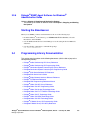
Post-Release Developments
1.
This section describes significant changes to the system release subsequent to the
general availability release date.
• Service Update for Dialogic® System Release 6.0 PCI for Windows® . . . . . . . 33
• Runtime Control of Single or Double Hookflash on Consultation Drop for FXS/LS
Protocol34
• Analog Call Transfer Support on Dialogic® Springware Boards . . . . . . . . . . . . 38
• Support for Windows Vista® Operating System . . . . . . . . . . . . . . . . . . . . . . . . 40
• Dialogic® DM3 Media Channel Reset Capability (Stuck Channel Recovery) . . 45
• AMD Opteron Server Support . . . . . . . . . . . . . . . . . . . . . . . . . . . . . . . . . . . . . 54
• Global DPD Enabled on Dialogic® Springware Boards . . . . . . . . . . . . . . . . . . 54
• Enhanced Special Information Tones on Dialogic® DM3 Boards Using Voice and
Global Call APIs55
• Troubleshooting Information for RTF Logs . . . . . . . . . . . . . . . . . . . . . . . . . . . . 66
• Remote Diagnostics Package . . . . . . . . . . . . . . . . . . . . . . . . . . . . . . . . . . . . . . 67
• New Parameter for Adjusting Silence Threshold on Dialogic® DM3 Boards. . . 69
• Support for PCI Express Boards - Dialogic® Station Interface Boards . . . . . . . 69
• Support for PCI Express Boards - Dialogic® DM/V-B Boards . . . . . . . . . . . . . . 70
• Support for Dialogic® D/4PCI Voice Board . . . . . . . . . . . . . . . . . . . . . . . . . . . . 73
• New Parameter for Adjusting Silence Threshold on Dialogic® DM3 Boards. . . 73
• File Management Enhancements for ISDNtrace Tool. . . . . . . . . . . . . . . . . . . . 74
• Support for Dialogic® DI/0408-LS-AR2 Board . . . . . . . . . . . . . . . . . . . . . . . . . 77
• Change in ipmedia.log Implementation . . . . . . . . . . . . . . . . . . . . . . . . . . . . . . 78
• Adjusting Pre-Record Beep Tone Characteristics through the CONFIG File . . 78
• Reduced Dial Tone Delay with MWI . . . . . . . . . . . . . . . . . . . . . . . . . . . . . . . . . 80
• Enhanced Diagnostics . . . . . . . . . . . . . . . . . . . . . . . . . . . . . . . . . . . . . . . . . . . 81
• Support for PCI Express Boards - Dialogic® Springware Boards . . . . . . . . . . . 83
• PDK Trace Supports CAS/R2MF/Tone Tracing. . . . . . . . . . . . . . . . . . . . . . . . . 86
• Ability to Lower or Disable White Noise . . . . . . . . . . . . . . . . . . . . . . . . . . . . . . 89
• Optional Use of Sharing of Timeslot (SOT) Algorithm . . . . . . . . . . . . . . . . . . . 90
• New FSK Transmit and Receive Signal Level Parameters . . . . . . . . . . . . . . . . 90
• Support for Reporting Billing Type . . . . . . . . . . . . . . . . . . . . . . . . . . . . . . . . . . 92
Dialogic® System Release 6.0 PCI for Windows® Release Update, Rev 62 — January 30, 2008
Dialogic Corporation
31
• Runtime Control of Double Answer for R2MF. . . . . . . . . . . . . . . . . . . . . . . . . . 94
• Enhanced ISDN Trace Functionality for DPNSS Tracing . . . . . . . . . . . . . . . . . 96
• Notification of Layer 1 Alarm Events on SS7 Boards . . . . . . . . . . . . . . . . . . . . 97
• Global Call Support for Time Slots on Dialogic® SS7 Boards Running in DTI Mode97
• Time Stamp for Tone-On/Off Events . . . . . . . . . . . . . . . . . . . . . . . . . . . . . . . . . 97
• New Fax Parameter for Modem Receive Level . . . . . . . . . . . . . . . . . . . . . . . . . 99
• Ability to Send and Receive DPNSS End to End Messages . . . . . . . . . . . . . . 100
• Enhancements to the Configuration Process . . . . . . . . . . . . . . . . . . . . . . . . . . 105
• New Option for dm3post Utility . . . . . . . . . . . . . . . . . . . . . . . . . . . . . . . . . . . . . 108
• New OAMIPC Mechanism Replaces CORBA . . . . . . . . . . . . . . . . . . . . . . . . . 108
• Support for Mixed ISDN and Clear Channel on Additional Dialogic® DM3 Boards109
• Detection of Unsupported Boards. . . . . . . . . . . . . . . . . . . . . . . . . . . . . . . . . . . 110
• PBX Integration Support for Nortel BCM . . . . . . . . . . . . . . . . . . . . . . . . . . . . . 111
• Enhancements to Runtime Trace Facility (RTF) Logging . . . . . . . . . . . . . . . . . 113
• Dynamically Retrieving and Modifying Selected Protocol Parameters When Using
Dialogic® DM3 Boards113
• Analog Line Adaptation Utility (LineAdapt) . . . . . . . . . . . . . . . . . . . . . . . . . . . . 137
• New QSIG Channel Mapping Parameter for E1 Boards . . . . . . . . . . . . . . . . . . 150
• IP Support on Dialogic® DI0408LSAR2 Boards . . . . . . . . . . . . . . . . . . . . . . . . 152
Note: With the inclusion of this new feature in the Service Update, installation of the
Service Update will make modifications as needed to the System Network
Configuration settings in the Windows® Registry in order to allow the IP
Media Service to modify the Type of Service (ToS) IP packet header fields of
RTP packets. This happens regardless of whether you use the ToS feature.
• Dialogic® DI0408LSAR2 Board Support for Host Systems with Multiple NICs. 159
• Support for QSIG NCAS Calls on Dialogic® DM3 Boards . . . . . . . . . . . . . . . . 161
• Loop Current Reversal Detection on Dialogic® DMV160LP Boards . . . . . . . . . 170
• Adjusting DTMF Characteristics through the CONFIG File . . . . . . . . . . . . . . . 174
• Single Board Start/Stop for Selected Dialogic®JCT Boards . . . . . . . . . . . . . . . 178
• SIP Call Transfer . . . . . . . . . . . . . . . . . . . . . . . . . . . . . . . . . . . . . . . . . . . . . . . . 182
• Early Media. . . . . . . . . . . . . . . . . . . . . . . . . . . . . . . . . . . . . . . . . . . . . . . . . . . . 213
• Global Call SS7 Enhancements . . . . . . . . . . . . . . . . . . . . . . . . . . . . . . . . . . . . 221
• Conference Bridging on Dialogic® DI Boards . . . . . . . . . . . . . . . . . . . . . . . . . . 221
• New Parameter for Order of DNIS and ANI . . . . . . . . . . . . . . . . . . . . . . . . . . . 222
• New Channel Block Timer for NTT Protocol . . . . . . . . . . . . . . . . . . . . . . . . . . . 223
Dialogic® System Release 6.0 PCI for Windows® Release Update, Rev 62 — January 30, 2008
Dialogic Corporation
32
• Mixing ISDN and CAS on Dialogic® DM/V-B Boards . . . . . . . . . . . . . . . . . . . . 225
• Implementation of ROLM Call Waiting LED . . . . . . . . . . . . . . . . . . . . . . . . . . . 227
• Enhanced Special Information Tone Frequency Detection on Dialogic® DM3 Boards
229
• Enhanced GCAMS on Dialogic® DM3 Boards . . . . . . . . . . . . . . . . . . . . . . . . . 233
• Telecom Subsystem Summary Tool (its_sysinfo) . . . . . . . . . . . . . . . . . . . . . . . 234
• Windows® Hardware Quality Labs (WHQL) Certification . . . . . . . . . . . . . . . . . 235
• Single Echo Canceller Convergence . . . . . . . . . . . . . . . . . . . . . . . . . . . . . . . . 235
• New Features in Dialogic® Global Call Protocols Package. . . . . . . . . . . . . . . . 238
• New Operating System Support . . . . . . . . . . . . . . . . . . . . . . . . . . . . . . . . . . . . 239
• New Station Interface Alarms . . . . . . . . . . . . . . . . . . . . . . . . . . . . . . . . . . . . . . 239
• Support for ANI Category Digit Retrieval on Dialogic® DM3 Boards . . . . . . . . 242
• New Media Load for Dialogic® DMV3600BP Boards . . . . . . . . . . . . . . . . . . . . 242
• New Media Loads for Dialogic® DMV1200BTEP Boards . . . . . . . . . . . . . . . . . 244
• New Media Load for Dialogic® DMV600BTEP Boards . . . . . . . . . . . . . . . . . . . 247
• Call Transfer Support on the Dialogic® DMV160LP Board . . . . . . . . . . . . . . . . 249
• dx_reciottdata( ) Enhancements . . . . . . . . . . . . . . . . . . . . . . . . . . . . . . . . . . . . 254
• Trunk Preconditioning . . . . . . . . . . . . . . . . . . . . . . . . . . . . . . . . . . . . . . . . . . . . 256
• Extended Board Management API Support for Dialogic® DM3 Boards . . . . . . 258
• New Boards Supported. . . . . . . . . . . . . . . . . . . . . . . . . . . . . . . . . . . . . . . . . . . 259
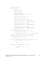
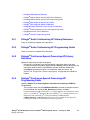
1.1
Service Update for Dialogic® System Release 6.0
PCI for Windows®
A Service Update for Dialogic® System Release 6.0 PCI for Windows® is now available.
Service Updates provide fixes to known problems, and may also introduce new
functionality. New versions of the Service Update are planned to be released periodically.
It is intended that this Release Update will document the features in the Service Updates.
Depending on whether you already have a version of Dialogic® System Release 6.0 PCI
for Windows® on your system, installing the Service Update will give you either a full
install or an update install:
• If you don’t have an existing version of System Release 6.0 PCI Windows on your
system, installing the Service Update gives you a full install of the system release.
You can select the features that you want to install, for example, Development
Dialogic® System Release 6.0 PCI for Windows® Release Update, Rev 62 — January 30, 2008
Dialogic Corporation
33
Package, Core Runtime Package, ISDN Protocols, Demos, SNMP Component
Manager, Global Call Protocols, and Documentation.
Note: With the Service Update, the Global Call Protocols Package can now be
installed as part of System Release 6.0 PCI Windows. Previously, this
package was installed separately.
The Development Package and Demos are available in the Developer Edition
only, not in the Redistributable Edition.
• If you have an existing version of System Release 6.0 PCI Windows on your system,
installing the Service Update gives you an update install. The update install gives
you the latest software for the features that you selected when you did the full install of
the system release that is currently on your system. If you want additional features,
such as the Global Call Protocols Package, you can use the Modify or Change option
as explained in the Installation Guide.
A new Dialogic® System Release 6.0 PCI for Windows® Software Installation Guide has
been added to the documentation bookshelf to describe the full install and update install
procedures. The Dialogic® Global Call Country Dependent Parameters (CDP) for PDK
Protocols Configuration Guide for the Global Call Protocols Package has also been added
to the bookshelf.
Note: Since the Global Call Protocols Package is now included with this Service Update version
of System Release 6.0 PCI Windows, the stand-alone protocols package should not be
used. (If you already have the stand-alone protocols package installed, you will be
prompted to remove it before installing the Service Update.) Do not install the stand-alone
protocols package after installing the Service Update (full install or update install), or your
software may become non-functional.
See the new Dialogic® System Release 6.0 PCI for Windows Software Installation Guide
on the documentation bookshelf for complete, detailed information about installing the
software.
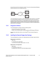
1.2
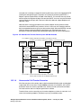
Runtime Control of Single or Double Hookflash on
Consultation Drop for FXS/LS Protocol
With the Service Update, runtime control of sending either a single or double hookflash
when dropping a consultation call on a supervised transfer is now supported for Dialogic®
DM3 Boards using the United States T1 FXS/LS Bidirectional protocol.
1.2.1
Feature Description
The signal pattern normally used by the FXS/LS protocol to drop a supervised transfer
consultation call is a single hookflash. For PBXs that require a double hookflash to drop a
consultation call, this can be set in the country dependent parameters (CDP) file for the
FXS/LS protocol, pdk_us_ls_fxs_io.cdp, by enabling the
CDP_AllowDblHookflashOnConsultationDrop parameter. (This parameter is disabled
Dialogic® System Release 6.0 PCI for Windows® Release Update, Rev 62 — January 30, 2008
Dialogic Corporation
34
by default.) CDP file parameters are set on a board basis. Parameter settings are static
and apply to all calls (per board).
However, some PBXs may require either a single or double hookflash depending on the
circumstances of the call. For example, a particular PBX may require:
• Single hookflash on consultation call drop if the call went through
• Double hookflash on consultation call drop if the call was in progress but did not go
through and never got connected (for example, call progress failure or call abort
before connect)
Note: These are only examples; the circumstances requiring a single or double hookflash can
vary depending the PBX. It is up to the application developer to determine when to apply a
single or double hookflash in any scenario or deployment.
For PBXs that require either a single or double hookflash, applications must be able to:
• Programmatically select either single or double hookflash when dropping a
consultation call in a supervised transfer
• Change this behavior on a call-by-call basis
Call Transfer Overview
An overview of call transfer is given elsewhere in this Release Update. See Section 1.3.1,
“Call Transfer Overview”, on page 38.
New Parameter for Single or Double Hookflash
Runtime control of single or double hookflash is implemented using the Dialogic® Global
Call gc_SetConfigData( ) function. The parameter settings in gc_SetConfigData( ) are
limited to the current call, that is, to the call reference number (CRN) specified as the
target_id in gc_SetConfigData( ). The CRN should be that of the consultation call. The
application should call gc_SetConfigData( ) with the correct hookflash value before
calling gc_DropCall( ) on the consultation call.
The gc_SetConfigData( ) function uses a GC_PARM_BLK data structure that contains
the configuration information. A new parmID,
GCPARM_CONSDROP_HKFLASH_OVERRIDE, is used to set the single or double
hookflash. As its name implies, this is a parameter to override the
CDP_AllowDblHookflashOnConsultationDrop parameter in the CDP file. It does so
only on a temporary basis and for a single consultation call. (See the Implementation
Guidelines section below for further information about related parameters in the CDP file.)
The GC_PARM_BLK structure is populated using the gc_util_insert_parm_val( )
function with the following values:
• parm_blkpp = pointer to the address of a valid GC_PARM_BLK structure where the
parameter and value are to be inserted
• setID = GCSET_CALLINFO
• parmID = GCPARM_CONSDROP_HKFLASH_OVERRIDE
Dialogic® System Release 6.0 PCI for Windows® Release Update, Rev 62 — January 30, 2008
Dialogic Corporation
35
• data_size = sizeof(int)
• data = One of the following values:
- GCPV_SINGLE_HKFLASH - single hookflash
- GCPV_DBL_HKFLASH - double hookflash
- GCPV_DISABLED - not set
Once the GC_PARM_BLK has been populated with the desired values, the
gc_SetConfigData( ) function can be issued to perform the configuration. The parameter
values for the gc_SetConfigData( ) function are as follows:
• target_type = GCTGT_CCLIB_CRN
• target_id = the call reference number (CRN) of the consultation call
• target_datap = pointer to the GC_PARM_BLK structure
• time_out = time-out in seconds
• update_cond = when to update (GCUPDATE_IMMEDIATE or GCUPDATE_ATNULL)
• request_idp = pointer to the location for storing the request ID
• mode = async or sync
For more detailed information about the gc_SetConfigData( ) function parameters, see
the Dialogic® Global Call API Library Reference.
The gc_GetConfigData( ) function returns the value previously set by
gc_SetConfigData( ) on the same CRN. If no previous setting occurred for that CRN,
GCPV_DISABLED is returned.
Implementation Guidelines
The following guidelines apply when implementing runtime control of single or double
hookflash:
• This feature is only available on Dialogic® DM3 Boards using the United States T1
FXS/LS Bidirectional protocol.
• The GCPARM_CONSDROP_HKFLASH_OVERRIDE parameter setting via
gc_SetConfigData( ) does not take effect until a gc_DropCall( ) on the consultation
call CRN is invoked. The application must invoke the gc_DropCall( ) with the
appropriate CRN for the parameter to take effect (that is, single or double hookflash
sent).
• In asynchronous mode, the application must update its state machine to wait for a
success event on the gc_SetConfigData( ) before a gc_DropCall( ) on the
consultation call is invoked.
• The GCPARM_CONSDROP_HKFLASH_OVERRIDE parameter has no effect on a
CRN other than the consultation call CRN resulting from a successful
gc_SetupTransfer( ).
• The setting of this parameter, and therefore the behavior for a drop on a consultation
call, is not retained for subsequent calls on the same channel, unless explicitly set on
each call.
Dialogic® System Release 6.0 PCI for Windows® Release Update, Rev 62 — January 30, 2008
Dialogic Corporation
36
The following guidelines discuss the use of the
GCPARM_CONSDROP_HKFLASH_OVERRIDE parameter with regard to the related
parameters in the pdk_us_ls_fxs_io.cdp file:
• The related parameters in the pdk_us_ls_fxs_io.cdp file are
CDP_AllowDblHookflashOnConsultationDrop and
CDP_BypassHookflashOnConsultationDrop. Both are disabled by default; the
default behavior is that a single hookflash is sent when dropping a consultation call.
• When CDP_AllowDblHookflashOnConsultationDrop is enabled, a double
hookflash is sent when dropping a consultation call.
• When CDP_BypassHookflashOnConsultationDrop is enabled, no hookflash is
sent when dropping a consultation call.
Note: Within the CDP file, the CDP_BypassHookflashOnConsultationDrop
setting takes precedence over
CDP_AllowDblHookflashOnConsultationDrop. But when
GCPARM_CONSDROP_HKFLASH_OVERRIDE is set via
gc_SetConfigData( ), its setting takes precedence over both of these CDP
file parameters for the consultation call with the specified CRN.
• When GCPARM_CONSDROP_HKFLASH_OVERRIDE is set, the values of the CDP
file parameters are not affected. However, the
GCPARM_CONSDROP_HKFLASH_OVERRIDE parameter overrides the values of
CDP_AllowDblHookflashOnConsultationDrop and
CDP_BypassHookflashOnConsultationDrop for the consultation call with the
specified CRN.
• If not set, the GCPARM_CONSDROP_HKFLASH_OVERRIDE parameter has no
default (GCPV_DISABLED). Whatever is set at configuration time with the
CDP_AllowDblHookflashOnConsultationDrop and
CDP_BypassHookflashOnConsultationDrop parameters in the
pdk_us_ls_fxs_io.cdp file will apply.
1.2.2
Documentation
The online bookshelf provided with Dialogic® System Release 6.0 PCI for Windows®
contains information about all system release features including features for application
development, configuration, administration, and diagnostics.
For more information about the Dialogic® Global Call API, see the following documents:
• Dialogic® Global Call API Programming Guide
• Dialogic® Global Call API Library Reference
For features specific to E1 and T1 technology, see:
• Dialogic® Global Call E1/T1 CAS/R2 Technology Guide
For information about the United States T1 FXS/LS Bidirectional protocol and CDP file,
see:
• Dialogic® Global Call Country Dependent Parameters (CDP) for PDK Protocols
Configuration Guide
Dialogic® System Release 6.0 PCI for Windows® Release Update, Rev 62 — January 30, 2008
Dialogic Corporation
37
1.3
Analog Call Transfer Support on Dialogic®
Springware Boards
With the Service Update, blind and supervised analog call transfers using the Dialogic®
Global Call API are now supported on Dialogic® Springware Boards.
Support for analog call transfer is applicable only to standard POTS (“plain old telephone
service”) line products. Proprietary private branch exchanges (PBXs) or key telephone
systems (KTSs) and their related boards, such as the Dialogic® D/42JCT-U and D/82JCTU PBX Integration Boards, are excluded from this feature since PBXs and KTSs may
provide proprietary protocols for call transfers.
Aside from the Dialogic® PBX Integration Boards, this feature can be used with all other
analog Springware boards that are supported in System Release 6.0 PCI Windows.
The following sections discuss:
• Call Transfer Overview
• Using Global Call with Analog Springware Boards
• Configuring the CDP File
• Documentation
1.3.1
Call Transfer Overview
There are two types of call transfers:
Supervised transfers
The person transferring the call stays on the line, announces the call, and consults
with the party to whom the call is being transferred before the transfer is completed.
Blind transfers
The call is sent without any consultation or announcement by the person transferring
the call. Blind transfers are also known as one-step or unsupervised transfers.
Supervised transfers use the following Global Call API functions:
gc_SetupTransfer( )
Initiates a supervised transfer.
gc_CompleteTransfer( )
Completes a supervised transfer.
gc_SwapHold( )
Switches between the consultation call and the call pending transfer.
Blind transfers use the following Global Call API function:
gc_BlindTransfer( )
Initiates and completes an unsupervised (one-step) transfer.
Dialogic® System Release 6.0 PCI for Windows® Release Update, Rev 62 — January 30, 2008
Dialogic Corporation
38
For further information about call transfers, see the Call State Models chapter of the
Dialogic® Global Call API Programming Guide.
1.3.2
Using Global Call with Analog Springware Boards
In order to use Global Call with analog Springware Boards:
• The Global Call Protocols package must be installed.
• The boards must be using the North American Analog Bidirectional PDK protocol,
pdk_na_an_io.
The Global Call Protocols package is one of the features that can be selected when
installing System Release 6.0 PCI Windows. If you have already installed System Release
6.0 PCI Windows without the Global Call Protocols, you can add it by using the Modify or
Change option as explained in the Dialogic® System Release 6.0 PCI for Windows®
Software Installation Guide.
With Springware Boards, the protocol is assigned when a Global Call device is opened
with the gc_OpenEx( ) function. For information about using PDK protocols, see the
Dialogic® Global Call Country Dependent Parameters (CDP) for PDK Protocols
Configuration Guide.
1.3.3
Configuring the CDP File
To support blind and supervised call transfers, the country dependent parameters file for
the North American Analog Bidirectional PDK protocol, pdk_na_an_io.cdp, has the
following new parameters that can be set by the user:
CDP_BtStartTimer
Description: For a supervised transfer, specifies the maximum time that the protocol
will wait after issuing hookflash as a part of gc_SetupTransfer( ) and before the
application issues gc_MakeCall( ).
For a blind transfer, specifies the maximum time that the protocol will wait after
issuing hookflash as a part of gc_BlindTransfer( ) and before the protocol completes
the digit dial. Since the call is made within Global Call, this parameter can be used as
a bail-out timer to dial tone detection when CDP_Detect_DialTone (Outbound) is
enabled and none is detected during the elapsed time.
Values: Time in milliseconds. Default is 8000 (8 seconds).
CDP_BlindXferTime
Description: Specifies the delay time between the third party ringing and the
controller going on-hook, i.e., disconnecting; it can be used to guard against network
latencies, ensuring that the end-to-end audio path has been established before
transfer.
Values: Time in milliseconds. Default is 2000 (2 seconds).
Dialogic® System Release 6.0 PCI for Windows® Release Update, Rev 62 — January 30, 2008
Dialogic Corporation
39
Other changes to the pdk_na_an_io.cdp file include:
SYS_FEATURES parameter now includes feature_transfer and feature_hold:
All CHARSTRING_t SYS_FEATURES = “feature_inbound,feature_outbound,
feature_DNIS,feature_ANI,feature_transfer,feature_hold”
New analog pulse signal:
All CAS_SIGNAL_ANALOG_PULSE_t CAS_HOOKFLASH = Hookflash
1.3.4
Documentation
The online bookshelf provided with Dialogic® System Release 6.0 PCI for Windows®
contains information about all system release features including features for application
development, configuration, administration, and diagnostics.
For more information about generic Dialogic® Global Call API features, see the following
documents:
• Dialogic® Global Call API Programming Guide
• Dialogic® Global Call API Library Reference
For features specific to Analog technology, see:
• Dialogic® Global Call Analog Technology Guide
For information about PDK protocols and CDP files, see:
• Dialogic® Global Call Country Dependent Parameters (CDP) for PDK Protocols
Configuration Guide
1.4
Support for Windows Vista® Operating System
With the Service Update, Dialogic® System Release 6.0 PCI for Windows® supports the
Windows Vista® operating system. The following versions of Windows Vista are
supported:
• Windows Vista Business, 32-bit edition
• Windows Vista Enterprise, 32-bit edition
• Windows Vista Ultimate, 32-bit edition
Note: The Dialogic® Software installation will be aborted if a 64-bit edition is detected.
When running System Release 6.0 PCI Windows on Windows Vista, only the following
Dialogic® Springware Boards are supported:
Dialogic® System Release 6.0 PCI for Windows® Release Update, Rev 62 — January 30, 2008
Dialogic Corporation
40
Dialogic® Boards Supported with Windows Vista® Operating Systems
PCI Boards
PCI Express Boards
D/4PCI
D/300JCT-E1
D/4PCIE-4F-W
D/480JCT-2T1-EW
D/4PCIU
D/320JCT
D/4PCIE-4S-W
D/600JCT-1E1-75-EW
D/4PCIUF
D/480JCT-1T1
D/41JCT-LS-EW
D/600JCT-1E1-120-EW
D/41JCT-LS
D/480JCT-2T1
D/120JCT-LS-EW
D/600JCT-2E1-75-EW
D/120JCT-LS
D/600JCT-1E1
D/240JCT-T1-EW
D/600JCT-2E1-120-EW
D/160JCT
D/600JCT-2E1
D/300JCT-E1-EW
VFX/41JCT-LS-EW
D/240JCT-T1
VFX/41JCT-LS
D/480JCT-1T1-EW
Note: Dialogic® DM3 Boards, SS7 Boards, and PBX Integration Boards are not currently supported with Windows Vista.
Support for additional boards is planned for future Service Update releases.
The following sections highlight some of the differences that users will see when running
System Release 6.0 PCI Windows on Windows Vista, as opposed to running on other
Windows® operating systems.
• Separate Install Media
• Content Split into Different Locations
• Changes to Environment Variables
• Building Applications
• Consent Dialog
• UDD Must Be Set to “Run as Administrator”
• WinHlp32.exe Not Included in Windows Vista
• RTF Logging
• Physical Address Extension
Separate Install Media
When you download System Release 6.0 PCI Windows from the Dialogic Support
website, note that there is a separate link for downloading the System Release version for
Windows Vista.
Content Split into Different Locations
In order to meet User Account Control and File Virtualization security features of Windows
Vista, those files that may require user modification of some sort have now been moved to
a non-restricted target folder. It is strongly advised to keep them in this or other equivalent
target location; otherwise, user modification of these files may be disallowed by the
operating system.
Dialogic® System Release 6.0 PCI for Windows® Release Update, Rev 62 — January 30, 2008
Dialogic Corporation
41
When installing System Release 6.0 PCI Windows on Windows Vista, you will be
prompted to enter two directory locations (rather than one) for storing Dialogic® System
Release Software files:
Choose Program File Destination Location
This is the directory where non-user-modifiable files in the System Release Software
will be installed. The default location is C:\Program Files\Dialogic.
Choose User-Modifiable File Destination Location
This is the directory where user-modifiable files in the System Release Software will
be installed. User-modifiable files include configuration files such as .prm and .cdp
files, and demo programs. The default location is C:\ProgramData\Dialogic.
Note: C:\ProgramData is a hidden directory.
Changes to Environment Variables
Because the Dialogic® System Release Software files are now installed under two
directory locations, it was necessary to make changes to the associated environment
variables. Three new variables are being introduced to enable internal components to
locate the non-modifiable cfg and data directories, and some of the existing variables
point to a different location for a Windows Vista install:
Environment Variable
Old Default Value
Windows Vista Default Value
INTEL_DIALOGIC_DIR
C:\Program Files\Dialogic
Unchanged
INTEL_DIALOGIC_BIN
C:\Program Files\Dialogic\bin
Unchanged
INTEL_DIALOGIC_CFG
C:\Program Files\Dialogic\cfg
C:\ProgramData\Dialogic\cfg
INTEL_DIALOGIC_FWL
C:\Program Files\Dialogic\data
C:\ProgramData\Dialogic\data
INTEL_DIALOGIC_INC
C:\Program Files\Dialogic\inc
Unchanged
INTEL_DIALOGIC_LIB
C:\Program Files\Dialogic\lib
Unchanged
INTEL_DIALOGIC_QSCRIPT
C:\Program Files\Dialogic\qscript
Unchanged
DIALOGIC_CFG_INTERNAL
N/A
C:\Program Files\Dialogic\cfg
DIALOGIC_FWL_BIN
N/A
C:\Program Files\Dialogic\data
DIALOGIC_USERDATA_DIR
N/A
C:\ProgramData\Dialogic
Building Applications
Starting with this release, applications must adhere to a minimum software development
environment. Validation has been achieved with Microsoft® Visual C++® versions that are
part of the Visual Studio® .NET 2003 and the Visual Studio 2005. In future Service
Updates, the Visual Studio .NET 2003 development environment support is planned to be
dropped; thus it is recommended that developers use the Visual Studio 2005 environment
instead.
Dialogic® System Release 6.0 PCI for Windows® Release Update, Rev 62 — January 30, 2008
Dialogic Corporation
42
Furthermore, Microsoft has dropped support of Visual Studio .NET 2002 or Visual Studio
.NET 2003 on Windows Vista, and has released the Visual Studio 2005 Service Pack 1
update for Windows Vista. Please refer to the following MSDN® pages for more
information:
• http://msdn2.microsoft.com/en-us/vstudio/aa948853.aspx
• http://msdn2.microsoft.com/en-us/vstudio/aa948854.aspx
The following table elaborates on version numbers and restrictions. Any development
environment prior to these is no longer supported.
Development Environment
Visual C++ Version
Dialogic Support
Visual Studio .NET 2003
Visual C++ Version 7.1
Restricted: Support is planned to be
dropped in a future System Release 6.0 PCI
Windows Service Update.
Visual Studio 2005
Visual C++ Version 8.0
No restrictions. Microsoft supported
environment for Windows Vista.
Consent Dialog
In order to meet User Account Control restrictions in Windows Vista, most of the Dialogic®
administration utilities have been adapted and embed a request for administration
privileges from the user invoking them. This is also known as requiring “elevation” or
requesting “administration tokens” from invoker. The user must belong to the
administrator's group. The shield icon (shown below) will decorate the icon on any
Dialogic® utility that requires elevation.
When the utility is invoked, it will request administration tokens, and if available, execution
is granted. However, unless the user is the system’s (sole) administrator account (as
opposed to belonging to the administrator group), a user consent dialog will still be
displayed by the operating system, and the user must confirm before execution can be
Dialogic® System Release 6.0 PCI for Windows® Release Update, Rev 62 — January 30, 2008
Dialogic Corporation
43
started. This is the way Windows Vista User Account Control works; this is not unique to
Dialogic® Software under Windows Vista. An example of a consent dialog is:
UDD Must Be Set to “Run as Administrator”
Dialogic® Diagnostics Software (UDD) works with Windows Vista; however, it lacks the
embedded request for administration tokens from the invoker, so execution will fail due to
this. In order to correct this problem, the user can manually set the appropriate rights. One
way to do this is by right-clicking on the UDD application icon located in the
INTEL_DIALOGIC_BIN directory, and in the Compatibility tab set it to “Run as
Administrator.”
WinHlp32.exe Not Included in Windows Vista
With the exception of the Installation Setup program, none of the Dialogic® GUI utilities,
demos, etc., have appropriate functional help. These utilities still use Windows Help,
which has been deprecated by Microsoft in favor of HTML help.
(Refer to the Microsoft document “The Windows Help (WinHlp32.exe) program is no
longer included in Windows operating systems starting with Windows Vista” at
http://support.microsoft.com/kb/917607/en-us.)
HTML help is not currently available for these Dialogic applications. As a workaround,
Microsoft allows end users to install a package with the Windows Help program; users can
download this package from:
http://www.microsoft.com/downloads/details.aspx?FamilyId=6EBCFAD9-D3F5-43658070-334CD175D4BB&displaylang=en
Dialogic® System Release 6.0 PCI for Windows® Release Update, Rev 62 — January 30, 2008
Dialogic Corporation
44
RTF Logging
With this release, Runtime Trace Facility (RTF) configuration and logging are only
available for users who have administrator privileges. The RTF Manager will not run
unless this condition is met.
In order for user applications to be able to generate RTF logs, the application must be run
as an administrator. This can be accomplished either by right-clicking the application icon
and selecting “Run As Administrator,” or by applying a manifest to the application
indicating that administrator rights are required.
Physical Address Extension
This release does not support systems running Windows with Physical Address Extension
(PAE). The installation will warn when PAE is detected on the host machine. The user
must disable PAE for proper Dialogic® System operation before any attempt to configure
or start boards in the system.
1.5
Dialogic® DM3 Media Channel Reset Capability
(Stuck Channel Recovery)
With the Service Update, whenever a media channel gets into a “stuck” state, there is a
way to recover that channel without having to restart the application or redownload the
board.
Note: A stuck channel is defined as a failure where the host application is unable to recover the
channel and no further media operations are possible on that channel until the application
is restarted or (in some cases) the board is redownloaded.
1.5.1
Feature Description
It has been observed, in rare occasions with high-density applications and high-load
systems, that media channels have become stuck and no further processing would take
place until the application is restarted or (in some cases) until the board is redownloaded.
This feature provides new API functions in the Dialogic® Voice library and in the Dialogic®
Continuous Speech Processing (CSP) library that enable the application to recover from
the stuck channel and return it to an idle and usable state.
Note: Not all stuck channels are recoverable. Also, not all errors are stuck channel errors. See
Section 1.5.3, “Restrictions and Limitations”, on page 53 for more information.
Supported Boards
All Dialogic® Media Span Boards support this media channel reset feature, namely
Dialogic® DM/V, DM/V-A, DM/V-B, and DM/IP Boards.
Dialogic® System Release 6.0 PCI for Windows® Release Update, Rev 62 — January 30, 2008
Dialogic Corporation
45
New APIs
The two new API functions are:
• dx_resetch( ) - Call this API to recover the media channel when the channel is stuck
and in a recoverable state. If the channel is recovered, a TDX_RESET event is
generated to the application, which enables the application to reuse the channel for
more media functions. If the channel is not in a recoverable state, a TDX_RESETERR
event is sent back to the application indicating that the specific channel is not
recoverable.
• ec_resetch( ) - Call this API to recover the CSP channel when the channel is stuck
and in a recoverable state. If the channel is recovered, TDX_RESET and
TEC_RESET events are generated to the application, which enables the application
to reuse the channel for more media functions. If the channel is not in a recoverable
state, TDX_RESETERR and TEC_RESETERR events are sent back to the
application indicating that the specific channel is not recoverable. Note that the
ec_resetch( ) function resets both the voice and the CSP channels.
Function reference information is provided next.
Dialogic® System Release 6.0 PCI for Windows® Release Update, Rev 62 — January 30, 2008
Dialogic Corporation
46
dx_resetch( )
Name: dx_resetch (chdev, mode)
Inputs: int chdev
• valid channel device handle
int mode
• mode of operation
Returns: 0 if success
-1 if failure
Includes: srllib.h
dxxxlib.h
Category: I/O
Mode: asynchronous or synchronous
Dialogic® DM3
Platform:
Description
The dx_resetch( ) function recovers a channel that is “stuck” (busy or hung) and in a recoverable
state, and brings it to an idle and usable state. This function blocks all other functions from
operating on the channel until the function completes.
Parameter
Description
chdev
Specifies the valid device handle obtained when the channel was opened
using dx_open( )
mode
Specifies the mode of operation:
• EV_ASYNC – asynchronous mode. The calling thread returns
immediately so it can process media functionality on other channels.
• EV_SYNC – synchronous mode. The calling thread waits until the
channel is recovered or discovers that the channel is not in a
recoverable state.
In synchronous mode, 0 is returned if the function completes successfully, and -1 is returned in
case of error.
In asynchronous mode, the TDX_RESET event is generated to indicate that the channel was
recovered and is in an idle and usable state. The TDX_RESETERR event is generated to indicate
that the channel is not recoverable. Issuing any other media calls on this channel will result in an
error.
Cautions
•
The dx_resetch( ) function is intended for use on channels that are stuck and not responding.
Do not use it in place of dx_stopch( ). Use dx_resetch( ) only if you do not receive an event
within 30 seconds of when it’s expected. Overuse of this function creates unnecessary
overhead and may affect system performance.
Dialogic® System Release 6.0 PCI for Windows® Release Update, Rev 62 — January 30, 2008
Dialogic Corporation
47
Errors
If the function returns -1, use the Dialogic® Standard Runtime Library (SRL) Standard Attribute
function ATDV_LASTERR( ) to obtain the error code or use ATDV_ERRMSGP( ) to obtain a
descriptive error message. One of the following error codes may be returned:
EDX_BADPARM
Invalid parameter
EDX_FWERROR
Firmware error
EDX_NOERROR
No error
Example
#include <srllib.h>
#include <dxxxlib.h>
main()
{
int chdev, srlmode;
/* Set SRL to run in polled mode. */
srlmode = SR_POLLMODE;
if (sr_setparm(SRL_DEVICE, SR_MODEID, (void *)&srlmode) == -1) {
/* process error */
}
/* Open the channel using dx_open( ). Get channel device descriptor in
* chdev.
*/
if ((chdev = dx_open("dxxxB1C1",NULL)) == -1) {
/* process error */
}
/* continue processing */
. .
/* Force the channel to idle state. The I/O function that the channel
* is executing will be terminated, and control passed to the handler
* function previously enabled, using sr_enbhdlr(), for the
* termination event corresponding to that I/O function.
* In asynchronous mode, dx_stopch() returns immediately,
* without waiting for the channel to go idle.
*/
if ( dx_stopch(chdev, EV_ASYNC) == -1) {
/* process error */
}
/* Wait for dx_stopch() to stop the channel and return the termination event
* for the present media function.
*/
/* After waiting for 30 secs if the termination event is not returned, issue a
* dx_resetch() to reset the channel.
*/
if (dx_resetch(chdev, EV_ASYNC) <0 )
{
/*process error */
Dialogic® System Release 6.0 PCI for Windows® Release Update, Rev 62 — January 30, 2008
Dialogic Corporation
48
}
/* Wait for TDX_RESET or TDX_RESETERR events */
}
See Also
•
ec_resetch( ) in the Dialogic® Continuous Speech Processing API Library Reference
Dialogic® System Release 6.0 PCI for Windows® Release Update, Rev 62 — January 30, 2008
Dialogic Corporation
49
ec_resetch( )
Name: ec_resetch (chdev, mode)
Inputs: int chdev
• valid channel device handle
int mode
• mode of operation
Returns: 0 if success
-1 if failure
Includes: srllib.h
eclib.h
Category: I/O
Mode: asynchronous or synchronous
Dialogic® DM3
Platform:
Description
The ec_resetch( ) function recovers a channel that is “stuck” (busy or hung) and in a recoverable
state, and brings it to an idle and usable state. This function blocks all other functions from
operating on the channel until the function completes. This function recovers both the CSP channel
and the voice channel.
Parameter
Description
chdev
Specifies the valid device handle obtained when the channel was opened
using dx_open( )
mode
Specifies the mode of operation:
• EV_ASYNC – asynchronous mode. The calling thread returns
immediately so it can process media functionality on other channels.
• EV_SYNC – synchronous mode. The calling thread waits until the
channel is recovered or discovers that the channel is not in a
recoverable state.
In synchronous mode, 0 is returned if the function completes successfully, and -1 is returned in
case of error.
In asynchronous mode, the TDX_RESET and the TEC_RESET events are generated to indicate
that the channel was recovered and is in an idle and usable state. The TDX_RESETERR and the
TEC_RESETERR events are generated to indicate that the channel is not recoverable. Issuing any
other media calls on this channel will result in an error.
Cautions
•
The ec_resetch( ) function is intended for use on channels that are stuck and not responding.
Do not use it in place of ec_stopch( ). Use ec_resetch( ) only if you do not receive an event
within 30 seconds of when it’s expected. Overuse of this function creates unnecessary
overhead and may affect system performance.
Dialogic® System Release 6.0 PCI for Windows® Release Update, Rev 62 — January 30, 2008
Dialogic Corporation
50
Errors
If the function returns -1, use the Dialogic® Standard Runtime Library (SRL) Standard Attribute
function ATDV_LASTERR( ) to obtain the error code or use ATDV_ERRMSGP( ) to obtain a
descriptive error message. One of the following error codes may be returned:
EDX_BADPARM
Invalid parameter
EDX_FWERROR
Firmware error
EDX_NOERROR
No error
Example
#include
#include
#include
#include
#include
<stdio.h>
<srllib.h>
<dxxxlib.h>
<eclib.h>
<errno.h> /* include in Linux applications only; exclude in Windows */
main()
{
int chdev, srlmode;
/* Set SRL to run in polled mode. */
srlmode = SR_POLLMODE;
if (sr_setparm(SRL_DEVICE, SR_MODEID, (void *)&srlmode) == -1) {
/* process error */
}
/* Open the channel using dx_open( ). Get channel device descriptor
* in chdev.
*/
if ((chdev = dx_open("dxxxB1C1",0)) == -1) {
/* process error */
}
/* continue processing */
. .
/* Force the channel to idle state. The I/O function that the channel
* is executing will be terminated, and control passed to the handler
* function previously enabled, using sr_enbhdlr(), for the
* termination event corresponding to that I/O function.
* In the asynchronous mode, ec_stopch() returns immediately,
* without waiting for the channel to go idle.
*/
if (ec_stopch(chdev, FULLDUPLEX, EV_ASYNC) == -1) {
/* process error */
}
/* Wait for the termination events (TEC_STREAM and/or TDX_PLAY) */
/* After waiting for 30 secs, if the channel is still in a busy state,
* issue ec_resetch() to reset both the CSP channel and the voice channel.
* When issued in asynchronous mode, it will return both (TEC_RESET/TEC_RESETERR)
* and (TDX_RESET/TDX_RESETERR) events.
*/
if (ec_resetch(chdev, EV_ASYNC)
/* process error */
}
== -1 ) {
Dialogic® System Release 6.0 PCI for Windows® Release Update, Rev 62 — January 30, 2008
Dialogic Corporation
51
/* Wait for TEC_RESET/TEC_RESETERR and TDX_RESET/TDX_RESETERR */
}
See Also
•
dx_resetch( ) in the Dialogic® Voice API Library Reference
Dialogic® System Release 6.0 PCI for Windows® Release Update, Rev 62 — January 30, 2008
Dialogic Corporation
52
1.5.2
Implementation Guidelines
The following guidelines apply when implementing the media channel reset capability
using the Dialogic® Voice API:
• It is recommended that you issue the function in asynchronous mode for more
efficient processing. In synchronous mode, the calling thread is blocked until the
function completes, which may take up to a minute in worst-case scenarios.
• The dx_resetch( ) function is intended for use on channels that are stuck and not
responding. Do not use it in place of dx_stopch( ). Use dx_resetch( ) only if you do
not receive an event within 30 seconds of when it’s expected. Overuse of this function
creates unnecessary overhead and may affect system performance.
• If you call dx_resetch( ) immediately following dx_stopch( ) without waiting at least
30 seconds for dx_stopch( ) to complete, you will not receive events, such as
TDX_PLAY and TDX_RECORD, even if the stop operation is successful and the
channel was not stuck. Instead, you will only receive the TDX_RESET event if the
channel recovery is successful or the TDX_RESETERR event if the channel is not
recoverable.
• If you call dx_resetch( ) without first using dx_stopch( ) to stop the channel, the
Voice library will internally call dx_stopch( ) and wait 30 seconds for it to complete. If
the internal stop channel is successful, you will receive the TDX_RESET event only. If
the internal stop channel is unsuccessful, the Voice library will then call
dx_resetch( ). Once a reset is attempted, you will receive the TDX_RESET event if
the channel recovery is successful or the TDX_RESETERR event if the channel is not
recoverable.
• Unrecoverable channels are written to a log file in the DebugAngel tool or the Runtime
Trace Facility (RTF) tool. See the Dialogic® System Software Diagnostics Guide for
more information on these tools.
The following guidelines apply when implementing the media channel reset capability
using the Dialogic® Continuous Speech Processing (CSP) API:
• The guidelines described for dx_resetch( ) and dx_stopch( ) apply to the
ec_resetch( ) and ec_stopch( ) functions in the CSP API.
• For CSP applications, it is recommended that you use ec_resetch( ) since this
function resets both the voice and the CSP channels. The dx_resetch( ) function
resets the voice channels only.
1.5.3
Restrictions and Limitations
The following restrictions and limitations apply to the media channel reset feature:
• This feature only addresses scenarios where the firmware and the host library have
lost synchronization or an event has not been propagated. DSP crashes, catastrophic
firmware failures (killtasks), or unsynchronized firmware state machines are not
recoverable without redownload of the board.
• This feature only addresses channels that become stuck while performing play and
record, tone generation, or FSK operations. It also addresses channels that become
stuck during CSP play or record operations.
Dialogic® System Release 6.0 PCI for Windows® Release Update, Rev 62 — January 30, 2008
Dialogic Corporation
53
• This feature does not address reset of IP media channels on Dialogic® DM/IP Boards.
It only addresses the reset of voice channels on DM/IP Boards.
• The reset may not succeed if CPU utilization on the host system is close to 100
percent. It is recommended that the CPU usage be at a reasonable level (less than 70
percent) before you attempt a channel reset.
1.5.4
Documentation
The online bookshelf provided with Dialogic® System Release 6.0 PCI for Windows®
contains information about all system release features including features for application
development, configuration, administration, and diagnostics.
For more information about the Dialogic® Voice API, see the following documents:
• Dialogic® Voice API Programming Guide
• Dialogic® Voice API Library Reference
For more information about the Dialogic® Continuous Speech Processing (CSP) API, see
the following documents:
• Dialogic® Continuous Speech Processing API Programming Guide
• Dialogic® Continuous Speech Processing API Library Reference
1.6
AMD Opteron Server Support
With the Service Update, Dialogic® System Release 6.0 PCI for Windows® has been
validated for use with Advanced Micro Devices, Inc. (AMD) Opteron server processors.
1.7
Global DPD Enabled on Dialogic® Springware
Boards
With the Service Update, Global Dial Pulse Detection (DPD) is now available by default
via software. Previously, this feature had to be enabled from the factory or by ordering a
separate GDPD enablement package to enable DPD on a board.
Global DPD is supported on Dialogic® Springware Boards, such as Dialogic® JCT Media
Boards and Dialogic® D/4PCIU Media Boards. Global DPD is not supported on Dialogic®
D/42JCT and D/82JCT PBX Integration Boards or on Dialogic® DM3 Media Boards.
For information about implementing Global DPD, see the Dialogic® Voice API
Programming Guide.
Dialogic® System Release 6.0 PCI for Windows® Release Update, Rev 62 — January 30, 2008
Dialogic Corporation
54
1.8
Enhanced Special Information Tones on Dialogic®
DM3 Boards Using Voice and Global Call APIs
With the Service Update, the user has the ability to detect new custom special information
tones (SITs) on Dialogic® DM3 Boards using the Dialogic® Voice API and Dialogic®
Global Call API. The new custom SITs are detected via the regular API events for
detecting call progress analysis outcome, and in particular, SIT tone detection. In addition,
create, query, and modify support of these new SIT tones and three existing default tones
via the Voice API is now available.
1.8.1
Feature Description
Predictive dialing applications, which are widely used in call centers, need to detect a
variety of SITs being used by Service Providers around the world. For this feature, the
Voice and Global Call APIs each provide an additional 15 SITs with customizable SIT
templates, which allow the user to detect a variety of nonstandard SITs used by Service
Providers. When the board firmware detects an incoming SIT tone during call progress
analysis, it tries to match it to one of the existing (default) templates. Tones that do not
match the default templates will be matched against the custom SIT templates created by
the user, and reported as such. If the SIT still does not fall into any of those two
categories, custom or standard, it may still be collected and reported as undetected
(SIT_ANY), and also reported back.
Voice API
For the Voice API, the 15 new custom tone templates (plus the existing default tone
templates) are supported for detection and reporting by the ATDX_CRTNID( ) function.
(For a description of the ATDX_CRTNID( ) function support on DM3 Boards, see
Section 1.59, “Enhanced Special Information Tone Frequency Detection on Dialogic®
DM3 Boards”, on page 229.)
For this feature, full create, query, and modify support has been added for the new custom
SITs and for three of the existing default SITs, via the dx_createtone( ), dx_querytone( ),
and dx_deletetone( ) functions, as follows:
#define
#define
#define
#define
#define
#define
#define
#define
#define
#define
#define
#define
#define
#define
#define
TID_CUSTOM_SIT1
TID_CUSTOM_SIT2
TID_CUSTOM_SIT3
TID_CUSTOM_SIT4
TID_CUSTOM_SIT5
TID_CUSTOM_SIT6
TID_CUSTOM_SIT7
TID_CUSTOM_SIT8
TID_CUSTOM_SIT9
TID_CUSTOM_SIT10
TID_CUSTOM_SIT11
TID_CUSTOM_SIT12
TID_CUSTOM_SIT13
TID_CUSTOM_SIT14
TID_CUSTOM_SIT15
Dialogic® System Release 6.0 PCI for Windows® Release Update, Rev 62 — January 30, 2008
Dialogic Corporation
55
#define TID_SIT_NC_INTERLATA
#define TID_SIT_RO_INTERLATA
#define TID_SIT_IO
For more information on modifying tone definitions, see the Dialogic® Voice API
Programming Guide.
Global Call API
For the Global Call API, 15 new custom SITs are allowed and are reported to the
application via the GCEV_DISCONNECTED event once any one of them is detected via
Global Call. The following table maps the custom SIT tone ID to the Global Call values:
Global Call Result Value
Tone ID
GCRV_SIT_UNKNOWN
(GCRV_RESULT | 0x70)
Description
0x38F
Custom SIT tone 1 detected
0x390
Custom SIT tone 2 detected
0x391
Custom SIT tone 3 detected
0x392
Custom SIT tone 4 detected
0x393
Custom SIT tone 5 detected
0x394
Custom SIT tone 6 detected
0x395
Custom SIT tone 7 detected
0x396
Custom SIT tone 8 detected
0x397
Custom SIT tone 9 detected
0x398
Custom SIT tone 10 detected
0x399
Custom SIT tone 11 detected
0x39A
Custom SIT tone 12 detected
0x39B
Custom SIT tone 13 detected
0x39C
Custom SIT tone 14 detected
0x39D
Custom SIT tone 15 detected
In addition, four new default SITs can be detected via Global Call. The following table
maps the Voice SITs to the new Global Call values:
Voice SIT
Global Call Result Value
Value
Global Call Error
Code
Value
Description
TID_SIT_ANY
GCRV_SIT_UNKNOWN
(GCRV_RESULT |
0x70)
EGC_SIT_
UNKNOWN
0x162
Unknown SIT
detected
TID_SIT_NC_INTERLATA
GCRV_NO_CIRCUIT_
INTERLATA
(GCRV_RESULT |
0x71)
EGC_NO_
CIRCUIT_
INTERLATA
0x163
No circuit
interlata SIT
detected
Dialogic® System Release 6.0 PCI for Windows® Release Update, Rev 62 — January 30, 2008
Dialogic Corporation
56
Voice SIT
Global Call Result Value
Value
Global Call Error
Code
Value
Description
TID_SIT_RO_INTERLATA
GCRV_REORDER_
INTERLATA
(GCRV_RESULT |
0x72)
EGC_REORDER
_INTERLATA
0x164
Reorder
interlata SIT
detected
TID_SIT_IO
GCRV_INEFFECTIVE_
OTHER
(GCRV_RESULT |
0x73)
EGC_INEFFECTI
VE_OTHER
0x165
Ineffective
other SIT
detected
1.8.2
Supported Boards
The following boards support this feature:
• Dialogic® DMV-B Media Boards
• Dialogic® DMV300BTEPEQ, DMV600BTEPEQ, and DMV1200BTEPEQ Media
Boards
• Dialogic® DISI Switching Boards
• Dialogic® DMV160LP Media Boards
• Dialogic® DMV and DMV-A Media Boards (ISDN or resource)
Note: DMV and DMV-A Media Boards running CAS, PDK (R2MF), and clear channel (ts16) do
not support this feature. Dialogic® DM/IP, HDSI, VFN, DM3 Fax, and CPI Fax Boards do
not support this feature. Refer to the table at the end of this section, PCD Files That Do
Not Support Enhanced Special Information Tones Feature, for a list of PCD files that are
excluded from this feature. If you attempt to use this feature with a board using one of
these PCD files, an error code is returned.
1.8.3
Example
The dx_createtone( ) function creates a new tone definition for a specific call progress
tone. On successful completion of the function, the TONE_DATA structure is used to
create a tone definition for the specified call progress tone.
Prior to creating a new tone definition with dx_createtone( ), use dx_querytone( ) to get
tone information for that tone, then use dx_deletetone( ) to delete that tone. The custom
SIT tone templates have empty on-board firmware definitions after board initialization.
The following is a code example for the TONE_DATA data structure using
TID_CUSTOM_SIT1 tone ID. The TONE_DATA structure is defined in dxxxlib.h.
#include "srllib.h"
#include "dxxxlib.h"
main()
{
int brdhdl; /* physical board device handle */
.
.
.
/* Open physical board */
if ((brdhdl = dx_open("brdB1",0)) == -1) {
printf("Cannot open board\n");
Dialogic® System Release 6.0 PCI for Windows® Release Update, Rev 62 — January 30, 2008
Dialogic Corporation
57
/* Perform system error processing */
exit(1);
}
/* Get the Tone Information for the TID_CUSTOM_SIT1 tone*/
int result;
TONE_DATA tonedata;
if ((result = dx_querytone(brdhdl, TID_CUSTOM_SIT1, &tonedata, EV_ASYNC)) == -1) {
printf("Cannot obtain tone information for TID_CUSTOM_SIT1 \n");
/* Perform system error processing */
exit(1);
}
/* Delete the current TID_CUSTOM_SIT1 call progress tone before creating a new definition*/
if ((result = dx_deletetone(brdhdl, TID_CUSTOM_SIT1, EV_ASYNC)) == -1) {
printf("Cannot delete the TID_CUSTOM_SIT1 tone\n");
/* Perform system error processing */
exit(1);
}
/* Change call progress default CUSTOM SIT tone */
tonedata.numofseg
= 3; /* triple segment tone */
tonedata.tn_rep_cnt = 1;
tonedata.toneseg[0].tn_dflag
= 0;
tonedata.toneseg[0].tn1_min
= 874;
tonedata.toneseg[0].tn1_max
= 955;
tonedata.toneseg[0].tn2_min
= 0;
tonedata.toneseg[0].tn2_max
= 0;
tonedata.toneseg[0].tn_twinmin = 0;
tonedata.toneseg[0].tn_twinmax = 0;
tonedata.toneseg[0].tnon_min
= 15;
tonedata.toneseg[0].tnon_max
= 30;
tonedata.toneseg[0].tnoff_min = 0;
tonedata.toneseg[0].tnoff_max = 5;
tonedata.toneseg[1].tn_dflag
tonedata.toneseg[1].tn1_min
tonedata.toneseg[1].tn1_max
tonedata.toneseg[1].tn2_min
tonedata.toneseg[1].tn2_max
tonedata.toneseg[1].tn_twinmin
tonedata.toneseg[1].tn_twinmax
tonedata.toneseg[1].tnon_min
tonedata.toneseg[1].tnon_max
tonedata.toneseg[1].tnoff_min
tonedata.toneseg[1].tnoff_max
=
=
=
=
=
=
=
=
=
=
=
0;
1310;
1410;
0;
0;
0;
0;
15;
30;
0;
5;
tonedata.toneseg[2].tn_dflag
= 0;
tonedata.toneseg[2].tn1_min
= 1845;
tonedata.toneseg[2].tn1_max
= 1950;
tonedata.toneseg[2].tn2_min
= 0;
tonedata.toneseg[2].tn2_max
= 0;
tonedata.toneseg[2].tn_twinmin = 0;
tonedata.toneseg[2].tn_twinmax = 0;
tonedata.toneseg[2].tnon_min
= 0;
tonedata.toneseg[2].tnon_max
= 0;
tonedata.toneseg[2].tnoff_min = 0;
if ((result = dx_createtone(brdhdl, TID_CUSTOM_SIT1, &tonedata, EV_SYNC)) == -1) {
printf("create tone for TID_CUSTOM_SIT1 failed\n");
/* Perform system error processing */
exit(1);
}
Dialogic® System Release 6.0 PCI for Windows® Release Update, Rev 62 — January 30, 2008
Dialogic Corporation
58
1.8.4
Documentation
The online bookshelf provided with Dialogic® System Release 6.0 PCI for Windows®
contains information about all system release features including features for application
development, configuration, administration, and diagnostics.
For more information about the Dialogic® Voice API, see the following documents:
• Dialogic® Voice API Programming Guide
• Dialogic® Voice API Library Reference
For more information about the Dialogic® Global Call API, see the following documents:
• Dialogic® Global Call API Programming Guide
• Dialogic® Global Call API Library Reference
Note: The following table lists PCD files that are excluded from this feature. If you attempt to
create, query, or delete any of the custom tones with a board using one of these PCD files,
error code EDX_TNQUERYDELETE is returned. Detection of the custom tones will not
work either. The Description column in the table reflects the same text displayed in the
Assign Firmware File dialog box when using the procedure described in Section 4.4,
Selecting a Configuration File Set, in the Dialogic® DM3 Architecture PCI Products on
Windows® Configuration Guide. For most products, the file names of the configuration file
set reflect the media load supported. If a media load number (mlx) is not present in the file
name, no media load is supported for that configuration. See Section 2.4.3, Media Load
Configuration File Sets, in the DM3 Configuration Guide for details on each of the board
families.
PCD Files That Do Not Support Enhanced Special Information Tones Feature
PCD File
(Unsupported)
Description
PCD File
(Unsupported)
Description
PCD File
(Unsupported)
Description
4x2_cas.pcd
DMV480_4T1 (BV 48
channels PSTN 4
Trunks CAS protocol)
ipvs_evr_2cas_
311.pcd
DM/IP481-2T1-100BT
(DM/IPLINK-T1_NIC,
1 daughterboard, 48
channels)
ml1b_qsa_cas.
pcd
DMV960_4T1
(BV+ADSI/FSK 96
channels PSTN 4
Trunks CAS protocol)
4x2_r2mf.pcd
DMV600_4E1 (BV 60
channels PSTN 4
Trunks R2MF
protocol)
ipvs_evr_2cas_
311c.pcd
DM/IP481-2T1-100BT
(DM/IPLINK-T1_NIC,
1 daughterboard, 48
channels)
ml1b_qsa_r2mf
.pcd
DMV1200_4E1
(BV+ADSI/FSK 120
channels PSTN 4
Trunks R2MF
protocol)
4xt_cas.pcd
DMT960_4T1 (PSTN
4 Trunks CAS
protocol)
ipvs_evr_2cas_
ml11_311c.pcd
DM/IP481-2T1-100BT
(DM/IPLINK-T1_NIC,
1 daughterboard, 48
channels)
ml1b_qsa_ts16
.pcd
DMV1200_4E1
(BV+ADSI/FSK 120
channels PSTN 4
Trunks TS16 protocol)
4xt_r2mf.pcd
DMT1200_4E1
(PSTN 4 Trunks
R2MF protocol)
ipvs_evr_2isdn
_4ess_311.pcd
DM/IP481-2T1
(DM/IPLINK-T1_NIC,
1 daughterboard, 48
channels)
ml2_dsa_cas.p
cd
DMV480A_2T1
(BV+CSP 48
channels PSTN 2
Trunks CAS protocol)
Note: List of PCD files that do not support enhanced special information tones is subject to change with each Service Update.
Dialogic® System Release 6.0 PCI for Windows® Release Update, Rev 62 — January 30, 2008
Dialogic Corporation
59
PCD Files That Do Not Support Enhanced Special Information Tones Feature
PCD File
(Unsupported)
Description
PCD File
(Unsupported)
Description
PCD File
(Unsupported)
Description
at_hdsi.pcd
HDSI
ipvs_evr_2isdn
_4ess_311c.pc
d
DM/IP481-2T1-100BT
(DM/IPLINK2T1_NIC, 1
daughterboard, 48
channels)
ml2_dsa_r2mf.
pcd
DMV600A_2E1
(BV+CSP 60
channels PSTN 2
Trunks R2MF
protocol)
at_hdsi_48_pla
y_rec.pcd
HDSI
ipvs_evr_2isdn
_4ess_ml11_3
11c.pcd
DM/IP481-2T1-100BT
(DM/IPLINK2T1_NIC, 1
daughterboard, 48
channels)
ml2_dsa_ts16.
pcd
DMV600A_2E1
(BV+CSP 60
channels PSTN 2
Trunks TS16 protocol)
at_hdsi_72_pla
y_rec.pcd
HDSI
ipvs_evr_2isdn
_5ess_311.pcd
DM/IP481-2T1
(DM/IPLINK-T1_NIC,
1 daughterboard, 48
channels)
ml2_qsa_cas.p
cd
DMV960_4T1
(BV+CSP 96
channels PSTN 4
Trunks CAS protocol)
at_hdsi_96_pla
y_rec.pcd
HDSI
ipvs_evr_2isdn
_5ess_311c.pc
d
DM/IP481-2T1-100BT
(DM/IPLINK2T1_NIC, 1
daughterboard, 48
channels)
ml2_qsa_r2mf.
pcd
DMV1200_4E1
(BV+CSP 120
channels PSTN 4
Trunks R2MF
protocol)
au_hdsi.pcd
HDSI
ipvs_evr_2isdn
_5ess_ml11_3
11c.pcd
DM/IP481-2T1-100BT
(DM/IPLINK2T1_NIC, 1
daughterboard, 48
channels)
ml2_qsa_ts16.
pcd
DMV1200_4E1
(BV+CSP 120
channels PSTN 4
Trunks TS16 protocol)
au_hdsi_48_pl
ay_rec.pcd
HDSI
ipvs_evr_2isdn
_dms_311.pcd
DM/IP481-2T1
(DM/IPLINK-T1_NIC,
1 daughterboard, 48
channels)
ml5bc_dsa_cas
.pcd
DMV480A_2T1
(BV+CSP+64EC+CS
PtoCTBus 48
channels Fax 12
channels PSTN 2
Trunks CAS protocol)
au_hdsi_72_pl
ay_rec.pcd
HDSI
ipvs_evr_2isdn
_dms_311c.pc
d
DM/IP481-2T1-100BT
(DM/IPLINK2T1_NIC, 1
daughterboard, 48
channels)
ml5bc_dsa_r2
mf.pcd
DMV600A_2E1
(BV+CSP+64EC+CS
PtoCTBus 60
channels Fax 12
channels PSTN 2
Trunks R2MF
protocol)
au_hdsi_96_pl
ay_rec.pcd
HDSI
ipvs_evr_2isdn
_dms_ml11_31
1c.pcd
DM/IP481-2T1-100BT
(DM/IPLINK2T1_NIC, 1
daughterboard, 48
channels)
ml5bc_dsa_ts1
6.pcd
DMV600A_2E1
(BV+CSP+64EC+CS
PtoCTBus 60
channels Fax 12
channels PSTN 2
Trunks TS16 protocol)
be_hdsi.pcd
HDSI
ipvs_evr_2isdn
_net5_311.pcd
DM/IP601-2E1
(DM/IPLINK-E1_NIC,
1 daughterboard, 60
channels)
mn_4xt_cas.pc
d
DMT960_4T1 (PSTN
4 Trunks CAS
protocol)
Note: List of PCD files that do not support enhanced special information tones is subject to change with each Service Update.
Dialogic® System Release 6.0 PCI for Windows® Release Update, Rev 62 — January 30, 2008
Dialogic Corporation
60
PCD Files That Do Not Support Enhanced Special Information Tones Feature
PCD File
(Unsupported)
Description
PCD File
(Unsupported)
Description
PCD File
(Unsupported)
Description
be_hdsi_48_pl
ay_rec.pcd
HDSI
ipvs_evr_2isdn
_net5_311c.pc
d
DM/IP601-2E1
(DM/IPLINK-E1_NIC,
1 daughterboard, 60
channels)
mn_4xt_r2mf.p
cd
DMT1200_4E1
(PSTN 4 Trunks
R2MF protocol)
be_hdsi_72_pl
ay_rec.pcd
HDSI
ipvs_evr_2isdn
_net5_ml11_31
1c.pcd
DM/IP601-2E1-100BT
(DM/IPLINK-E1_NIC,
1 daughterboard, 60
channels)
mn_4xt_ts16.p
cd
DMT1200_4E1
(PSTN 4 Trunks TS16
protocol)
be_hdsi_96_pl
ay_rec.pcd
HDSI
ipvs_evr_2isdn
_net5_ts16_31
1.pcd
DM/IP601-2E1
(DM/IPLINK-E1_NIC,
1 daughterboard, 60
channels)
mx_hdsi.pcd
HDSI
ch_hdsi.pcd
HDSI
ipvs_evr_2isdn
_ni2_311.pcd
DM/IP481-2T1
(DM/IPLINK-T1_NIC,
1 daughterboard, 48
channels)
mx_hdsi_48_pl
ay_rec.pcd
HDSI
ch_hdsi_48_pla
y_rec.pcd
HDSI
ipvs_evr_2isdn
_ni2_311c.pcd
DM/IP481-2T1-100BT
(DM/IPLINK2T1_NIC, 1
daughterboard, 48
channels)
mx_hdsi_72_pl
ay_rec.pcd
HDSI
ch_hdsi_72_pla
y_rec.pcd
HDSI
ipvs_evr_2isdn
_ni2_ml11_311
c.pcd
DM/IP481-2T1-100BT
(DM/IPLINK2T1_NIC, 1
daughterboard, 48
channels)
mx_hdsi_96_pl
ay_rec.pcd
HDSI
ch_hdsi_96_pla
y_rec.pcd
HDSI
ipvs_evr_2isdn
_ntt_311.pcd
DM/IP481-2T1
(DM/IPLINK-T1_NIC,
1 daughterboard, 48
channels)
my_hdsi.pcd
HDSI
cpi400bripcipm
p.pcd
CPi/400 BRI-PCI
Point to Multipoint
ipvs_evr_2isdn
_ntt_311c.pcd
DM/IP481-2T1-100BT
(DM/IPLINK2T1_NIC, 1
daughterboard, 48
channels)
my_hdsi_48_pl
ay_rec.pcd
HDSI
cpi400bripcipp.
pcd
CPi/400 BRI-PCI
Point to Point
ipvs_evr_2isdn
_ntt_ml11_311
c.pcd
DM/IP481-2T1-100BT
(DM/IPLINK2T1_NIC, 1
daughterboard, 48
channels)
my_hdsi_72_pl
ay_rec.pcd
HDSI
de_hdsi.pcd
HDSI
ipvs_evr_2isdn
_qsige1_311.p
cd
DM/IP601-2E1
(DM/IPLINK-E1_NIC,
1 daughterboard, 60
channels)
my_hdsi_96_pl
ay_rec.pcd
HDSI
de_hdsi_48_pl
ay_rec.pcd
HDSI
ipvs_evr_2isdn
_qsige1_311c.
pcd
DM/IP601-2E1
(DM/IPLINK-E1_NIC,
1 daughterboard, 60
channels)
nl_hdsi.pcd
HDSI
Note: List of PCD files that do not support enhanced special information tones is subject to change with each Service Update.
Dialogic® System Release 6.0 PCI for Windows® Release Update, Rev 62 — January 30, 2008
Dialogic Corporation
61
PCD Files That Do Not Support Enhanced Special Information Tones Feature
PCD File
(Unsupported)
Description
PCD File
(Unsupported)
Description
PCD File
(Unsupported)
Description
de_hdsi_72_pl
ay_rec.pcd
HDSI
ipvs_evr_2isdn
_qsige1_ml11_
311c.pcd
DM/IP601-2E1-100BT
(DM/IPLINK-E1_NIC,
1 daughterboard, 60
channels)
nl_hdsi_48_pla
y_rec.pcd
HDSI
de_hdsi_96_pl
ay_rec.pcd
HDSI
ipvs_evr_2isdn
_qsigt1_311.pc
d
DM/IP481-2T1
(DM/IPLINK-T1_NIC,
1 daughterboard, 48
channels)
nl_hdsi_72_pla
y_rec.pcd
HDSI
dk_hdsi.pcd
HDSI
ipvs_evr_2isdn
_qsigt1_311c.p
cd
DM/IP481-2T1-100BT
(DM/IPLINK2T1_NIC, 1
daughterboard, 48
channels)
nl_hdsi_96_pla
y_rec.pcd
HDSI
dk_hdsi_48_pla
y_rec.pcd
HDSI
ipvs_evr_2isdn
_qsigt1_ml11_
311c.pcd
DM/IP481-2T1-100BT
(DM/IPLINK2T1_NIC, 1
daughterboard, 48
channels)
no_hdsi.pcd
HDSI
dk_hdsi_72_pla
y_rec.pcd
HDSI
ipvs_evr_2r2mf
_311.pcd
DM/IP601-2E1-100BT
no_hdsi_48_pl
ay_rec.pcd
HDSI
dk_hdsi_96_pla
y_rec.pcd
HDSI
ipvs_evr_2r2mf
_311c.pcd
DM/IP601-2E1-100BT
(DM/IPLINK-E1_NIC)
no_hdsi_72_pl
ay_rec.pcd
HDSI
es_hdsi.pcd
HDSI
ipvs_evr_2r2mf
_ml11_311c.pc
d
DM/IP601-2E1-100BT
(DM/IPLINK-E1_NIC,
1 daughterboard, 60
channels)
no_hdsi_96_pl
ay_rec.pcd
HDSI
es_hdsi_48_pla
y_rec.pcd
HDSI
ipvs_evr_cas_3
11.pcd
DM/IP241-T1
(DM/IPLINK-T1_NIC)
nz_hdsi.pcd
HDSI
es_hdsi_72_pla
y_rec.pcd
HDSI
ipvs_evr_cas_
ml11_311.pcd
DM/IP241-T1
(DM/IPLINK-T1_NIC)
nz_hdsi_48_pla
y_rec.pcd
HDSI
es_hdsi_96_pla
y_rec.pcd
HDSI
ipvs_evr_isdn_
4ess_311.pcd
DM/IP241-1T1-100BT
(DM/IPLINK-T1_NIC,
1 daughterboard, 24
channels)
nz_hdsi_72_pla
y_rec.pcd
HDSI
fax24.pcd
DM/F240-PCI - 24
Ch. Fax
ipvs_evr_isdn_
4ess_ml11_31
1.pcd
DM/IP241-1T1-100BT
(DM/IPLINK-T1_NIC,
1 daughterboard, 24
channels)
nz_hdsi_96_pla
y_rec.pcd
HDSI
fax30.pcd
DM/F300-PCI - 30
Ch. Fax
ipvs_evr_isdn_
5ess_311.pcd
DM/IP241-1T1-100BT
(DM/IPLINK-T1_NIC,
1 daughterboard, 24
channels)
pt_hdsi.pcd
HDSI
fn_isdn_4ess.p
cd
DM/F240-1T1-PCI T1 w/24 Ch. Fax FN
ipvs_evr_isdn_
5ess_ml11_31
1.pcd
DM/IP241-1T1-100BT
(DM/IPLINK-T1_NIC,
1 daughterboard, 24
channels)
pt_hdsi_48_pla
y_rec.pcd
HDSI
Note: List of PCD files that do not support enhanced special information tones is subject to change with each Service Update.
Dialogic® System Release 6.0 PCI for Windows® Release Update, Rev 62 — January 30, 2008
Dialogic Corporation
62
PCD Files That Do Not Support Enhanced Special Information Tones Feature
PCD File
(Unsupported)
Description
PCD File
(Unsupported)
Description
PCD File
(Unsupported)
Description
fn_isdn_5ess.p
cd
DM/F240-1T1-PCI T1 w/24 Ch. Fax FN
ipvs_evr_isdn_
dms_311.pcd
DM/IP241-1T1
(DM/IPLINK-T1_NIC,
1 daughterboard, 24
channels)
pt_hdsi_72_pla
y_rec.pcd
HDSI
fn_isdn_dms.pc
d
DM/F240-1T1-PCI T1 w/24 Ch. Fax FN
ipvs_evr_isdn_
dms_ml11_311
.pcd
DM/IP241-1T1
(DM/IPLINK-T1_NIC,
1 daughterboard, 24
channels)
pt_hdsi_96_pla
y_rec.pcd
HDSI
fn_isdn_net5.p
cd
DM/F300-1E1-PCI E1 w/30 Ch. Fax FN
ipvs_evr_isdn_
net5_311.pcd
DM/IP301-1E1-100BT
(DM/IPLINK-E1_NIC,
1 daughterboard, 30
channels)
qs_cas.pcd
DMV960_4T1 (BV 96
channels PSTN 4
Trunks CAS protocol)
fn_isdn_ni2.pcd
DM/F240-1T1-PCI T1 w/24 Ch. Fax FN
ipvs_evr_isdn_
net5_ml11_311
.pcd
DM/IP301-1E1-100BT
(DM/IPLINK-E1_NIC,
1 daughterboard, 30
channels)
qs_r2mf.pcd
DMV1200_4E1 (BV
120 channels PSTN 4
Trunks R2MF
protocol)
fn_isdn_ntt.pcd
DM/F240-1T1-PCI T1 w/24 Ch. Fax FN
ipvs_evr_isdn_
ni2_311.pcd
DM/IP241-1T1-100BT
(DM/IPLINK-T1_NIC,
1 daughterboard, 24
channels)
se_hdsi.pcd
HDSI
fn_isdn_qsige1.
pcd
DM/F300-1E1-PCI E1 w/30 Ch. Fax FN
ipvs_evr_isdn_
ni2_ml11_311.
pcd
DM/IP241-1T1-100BT
(DM/IPLINK-T1_NIC,
1 daughterboard, 24
channels)
se_hdsi_48_pla
y_rec.pcd
HDSI
fn_isdn_qsigt1.
pcd
DM/F240-1T1-PCI T1 w/23 Ch. Fax FN
ipvs_evr_isdn_
ntt_311.pcd
DM/IP241-1T1-100BT
(DM/IPLINK-T1_NIC,
1 daughterboard, 23
channels)
se_hdsi_72_pla
y_rec.pcd
HDSI
fn_r2mf.pcd
DM/F300-1E1-PCI E1 w/30 Fax
Channels FN
ipvs_evr_isdn_
ntt_ml11_311.p
cd
DM/IP241-1T1-100BT
(DM/IPLINK-T1_NIC,
1 daughterboard, 23
channels)
se_hdsi_96_pla
y_rec.pcd
HDSI
fn_t1.pcd
DM/F240-1T1-PCI T1 w/24 Ch. Fax FN
ipvs_evr_isdn_
qsige1_311.pc
d
DM/IP301-1E1-100BT
(DM/IPLINK-E1_NIC,
1 daughterboard, 30
channels)
sg_hdsi.pcd
HDSI
fn3_isdn_4ess.
pcd
DM/F240-1T1-PCI T1 w/24 Ch. Fax FN3
ipvs_evr_isdn_
qsige1_ml11_3
11.pcd
DM/IP301-1E1-100BT
(DM/IPLINK-E1_NIC,
1 daughterboard, 30
channels)
sg_hdsi_48_pla
y_rec.pcd
HDSI
fn3_isdn_5ess.
pcd
DM/F240-1T1-PCI T1 w/24 Ch. Fax FN3
ipvs_evr_isdn_
qsigt1_311.pcd
DM/IP241-1T1-100BT
(DM/IPLINK-T1_NIC,
1 daughterboard, 23
channels)
sg_hdsi_72_pla
y_rec.pcd
HDSI
Note: List of PCD files that do not support enhanced special information tones is subject to change with each Service Update.
Dialogic® System Release 6.0 PCI for Windows® Release Update, Rev 62 — January 30, 2008
Dialogic Corporation
63
PCD Files That Do Not Support Enhanced Special Information Tones Feature
PCD File
(Unsupported)
PCD File
(Unsupported)
PCD File
(Unsupported)
Description
fn3_isdn_dms.
pcd
DM/F240-1T1-PCI T1 w/24 Ch. Fax FN3
ipvs_evr_isdn_
qsigt1_ml11_3
11.pcd
DM/IP241-1T1-100BT
(DM/IPLINK-T1_NIC,
1 daughterboard, 23
channels)
sg_hdsi_96_pla
y_rec.pcd
HDSI
fn3_isdn_net5.
pcd
DM/F300-1E1-PCI E1 w/30 Ch. Fax FN3
ipvs_evr_r_311
.pcd
DM/IP601-2E1
(DM/IPLINK-E1_NIC,
1 daughterboard, 60
channels)
ul2_qsa_cas.pc
d
DMV960_4T1
(BV+CSP 96
channels CONF+EC
15 channels Fax 4
channels PSTN 4
Trunks CAS protocol)
fn3_isdn_ni2.pc
d
DM/F240-1T1-PCI T1 w/24 Ch. Fax FN3
ipvs_evr_r_311
_ml1a.pcd
DM/IP601-2E1
(DM/IPLINK-E1_NIC,
1 daughterboard, 60
channels)
ul1_qsa_*e1IS
DNprot*.pcd
DMV1200_4E1 (BV
60 channels
CONF+EC 60
channels Fax 8
channels PSTN 4
Trunks DPNSS
protocol)
fn3_isdn_ntt.pc
d
DM/F240-1T1-PCI T1 w/24 Ch. Fax FN3
ipvs_evr_r_311
c.pcd
DM/IP1200
(Resource Only
board)
ul2_qsa_*t1ISD
Nprot*.pcd
DMV960_4T1
(BV+CSP 96
channels CONF+EC
15 channels Fax 4
channels PSTN 4
Trunks QSIGT1
protocol)
fn3_isdn_qsige
1.pcd
DM/F300-1E1-PCI E1 w/30 Ch. Fax FN3
ipvs_evr_r_ml1
1_311c.pcd
DM/IP1200
(Resource Only
board)
us_hdsi.pcd
HDSI
fn3_isdn_qsigt1
.pcd
DM/F240-1T1-PCI T1 w/23 Ch. Fax FN3
ipvs_evr_r2mf_
311.pcd
DM/IP301-E1
(DM/IPLINK-E1_NIC)
us_hdsi_48_pla
y_rec.pcd
HDSI
fn3_r2mf.pcd
DM/F300-1E1-PCI E1 w/30 Fax
Channels FN3
ipvs_evr_r2mf_
ml11_311.pcd
DM/IP301-E1
(DM/IPLINK-E1_NIC)
us_hdsi_72_pla
y_rec.pcd
HDSI
fn3_t1.pcd
DM/F240-1T1-PCI T1 w/24 Ch. Fax FN3
ipvs_evr_ts16_
ml11_311.pcd
DM/IP301-1E1-100BT
(DM/IPLINK-E1_NIC,
1 daughterboard, 30
channels)
us_hdsi_96_pla
y_rec.pcd
HDSI
fr_hdsi.pcd
HDSI
it_hdsi.pcd
HDSI
vfn_isdn_4ess.
pcd
DM/VF240-1T1-PCI T1 w/24 Ch. Fax VFN
fr_hdsi_48_play
_rec.pcd
HDSI
it_hdsi_48_play
_rec.pcd
HDSI
vfn_isdn_5ess.
pcd
DM/VF240-1T1-PCI T1 w/24 Ch. Fax VFN
fr_hdsi_72_play
_rec.pcd
HDSI
it_hdsi_72_play
_rec.pcd
HDSI
vfn_isdn_dms.p
cd
DM/VF240-1T1-PCI T1 w/24 Ch. Fax VFN
fr_hdsi_96_play
_rec.pcd
HDSI
it_hdsi_96_play
_rec.pcd
HDSI
vfn_isdn_net5.
pcd
DM/VF300-1E1-PCI E1 w/30 Ch. Fax VFN
gb_hdsi.pcd
HDSI
jp_hdsi.pcd
HDSI
vfn_isdn_ni2.pc
d
DM/VF240-1T1-PCI T1 w/24 Ch. Fax VFN
Description
Description
Note: List of PCD files that do not support enhanced special information tones is subject to change with each Service Update.
Dialogic® System Release 6.0 PCI for Windows® Release Update, Rev 62 — January 30, 2008
Dialogic Corporation
64
PCD Files That Do Not Support Enhanced Special Information Tones Feature
PCD File
(Unsupported)
Description
PCD File
(Unsupported)
Description
PCD File
(Unsupported)
Description
gb_hdsi_48_pl
ay_rec.pcd
HDSI
jp_hdsi_48_pla
y_rec.pcd
HDSI
vfn_isdn_ntt.pc
d
DM/VF240-1T1-PCI T1 w/24 Ch. Fax VFN
gb_hdsi_72_pl
ay_rec.pcd
HDSI
jp_hdsi_72_pla
y_rec.pcd
HDSI
vfn_isdn_qsige
1.pcd
DM/VF300-1E1-PCI E1 w/30 Ch. Fax VFN
gb_hdsi_96_pl
ay_rec.pcd
HDSI
jp_hdsi_96_pla
y_rec.pcd
HDSI
vfn_isdn_qsigt1
.pcd
DM/VF240-1T1-PCI T1 w/23 Ch. Fax VFN
gdk_isdn_4ess.
pcd
Cpi/2400CT-T1 ISDN
4ESS with 24 Fax
Channels
lu_hdsi.pcd
HDSI
vfn_r2mf.pcd
DM/VF300-1E1-PCI E1 w/30 Fax
Channels VFN
gdk_isdn_5ess.
pcd
Cpi/2400CT-T1 ISDN
5ESS with 24 Fax
Channels
lu_hdsi_48_pla
y_rec.pcd
HDSI
vfn_t1.pcd
DM/VF240-1T1-PCI T1 w/24 Ch. Fax VFN
gdk_isdn_dms.
pcd
Cpi/2400CT-T1 ISDN
DMS with 24 Fax
Channels
lu_hdsi_72_pla
y_rec.pcd
HDSI
vfn3_isdn_4ess
.pcd
DM/VF240-1T1-PCI T1 w/24 Ch. Fax
VFN3
gdk_isdn_net5.
pcd
Cpi/3000CT-E1 ISDN
NET5 with 30 Fax
Channels
lu_hdsi_96_pla
y_rec.pcd
HDSI
vfn3_isdn_5ess
.pcd
DM/VF240-1T1-PCI T1 w/24 Ch. Fax
VFN3
gdk_isdn_ntt.pc
d
Cpi/2400CT-T1 ISDN
NTT with 24 Fax
Channels
ml1_4x2_cas.p
cd
DMV480_4T1 (BV 48
channels PSTN 4
Trunks CAS protocol)
vfn3_isdn_dms.
pcd
DM/VF240-1T1-PCI T1 w/24 Ch. Fax
VFN3
gdk_t1_em.pcd
CPi/2400CT-T1 CAS
E&M with 24 Fax
Channels
ml1_4x2_r2mf.
pcd
DMV600_4E1 (BV 60
channels PSTN 4
Trunks R2MF
protocol)
vfn3_isdn_net5
.pcd
DM/VF300-1E1-PCI E1 w/30 Ch. Fax
VFN3
gdk_t1_gs.pcd
CPi/2400CT-T1 with
24 Fax Channels
ml1_4x2_ts16.
pcd
DMV600_4E1 (BV 60
channels PSTN 4
Trunks TS16 protocol)
vfn3_isdn_ni2.p
cd
DM/VF240-1T1-PCI T1 w/24 Ch. Fax
VFN3
gdk_t1_ls.pcd
CPi/2400CT-T1 T1
CAS Loop Start with
24 Fax Channels
ml1_qs_cas.pc
d
DMV960_4T1 (BV 96
channels PSTN 4
Trunks CAS protocol)
vfn3_isdn_ntt.p
cd
DM/VF240-1T1-PCI T1 w/24 Ch. Fax
VFN3
hk_hdsi.pcd
HDSI
ml1_qs_r2mf.p
cd
DMV1200_4E1 (BV
120 channels PSTN 4
Trunks R2MF
protocol)
vfn3_isdn_qsig
e1.pcd
DM/VF300-1E1-PCI E1 w/30 Ch. Fax
VFN3
hk_hdsi_48_pla
y_rec.pcd
HDSI
ml1_qs_ts16.pc
d
DMV1200_4E1 (BV
120 channels PSTN 4
Trunks TS16 protocol)
vfn3_isdn_qsigt
1.pcd
DM/VF240-1T1-PCI T1 w/23 Ch. Fax
VFN3
hk_hdsi_72_pla
y_rec.pcd
HDSI
ml10_dsa_cas.
pcd
DMV480A_2T1
(BV+CSP 48
channels CONF+EC
60 channels PSTN 2
Trunks CAS protocol)
vfn3_r2mf.pcd
DM/VF300-1E1-PCI E1 w/30 Fax
Channels VFN3
Note: List of PCD files that do not support enhanced special information tones is subject to change with each Service Update.
Dialogic® System Release 6.0 PCI for Windows® Release Update, Rev 62 — January 30, 2008
Dialogic Corporation
65
PCD Files That Do Not Support Enhanced Special Information Tones Feature
PCD File
(Unsupported)
Description
PCD File
(Unsupported)
Description
PCD File
(Unsupported)
Description
hk_hdsi_96_pla
y_rec.pcd
HDSI
ml10_dsa_r2mf
.pcd
DMV600A_2E1
(BV+CSP 60
channels CONF+EC
60 channels PSTN 2
Trunks R2MF
protocol)
vfn3_t1.pcd
DM/VF240-1T1-PCI T1 w/24 Ch. Fax
VFN3
ie_hdsi.pcd
HDSI
ml10_dsa_ts16
.pcd
DMV600A_2E1
(BV+CSP 60
channels CONF+EC
60 channels PSTN 2
Trunks TS16 protocol)
za_hdsi.pcd
HDSI
ie_hdsi_48_pla
y_rec.pcd
HDSI
ml1b_dsa_cas.
pcd
DMV480A_2T1
(BV+ADSI/FSK 48
channels PSTN 2
Trunks CAS protocol)
za_hdsi_48_pla
y_rec.pcd
HDSI
ie_hdsi_72_pla
y_rec.pcd
HDSI
ml1b_dsa_r2mf
.pcd
DMV600A_2E1
(BV+ADSI/FSK 60
channels PSTN 2
Trunks R2MF
protocol)
za_hdsi_72_pla
y_rec.pcd
HDSI
ie_hdsi_96_pla
y_rec.pcd
HDSI
ml1b_dsa_ts16
.pcd
DMV600A_2E1
(BV+ADSI/FSK 60
channels PSTN 2
Trunks TS16 protocol)
za_hdsi_96_pla
y_rec.pcd
HDSI
Note: List of PCD files that do not support enhanced special information tones is subject to change with each Service Update.
1.9
Troubleshooting Information for RTF Logs
To assist in troubleshooting, a table showing runtime and firmware errors that may appear
in Dialogic® Runtime Trace Facility (RTF) logs is now available. You can get a description
of errors and the suggested action to resolve the error. To access the table, use this link:
• Error Code Table
For runtime errors, the table provides the following information:
Internal error value
The error code detected internally by the library. In some of the libraries, more than
one internal error is mapped to an end user error. When contacting support about
failures, this information will be helpful to the support engineer because it provides
more specific information about why the error was generated. This number may
appear in the RTF log (with the end user error value).
Note: Sometimes the internal error value and end user error value are listed in the
same trace entry. Sometimes the internal error value may appear as a
separate entry.
End user error
The name of the constant that is documented in the library API reference.
Dialogic® System Release 6.0 PCI for Windows® Release Update, Rev 62 — January 30, 2008
Dialogic Corporation
66
End user error value
The numeric value of the constant that is documented in the library API reference.
This is the value that will appear in the RTF log, which you can then search for in the
table.
Description of the error
A textual description of the error.
Action to be taken
The suggested action to resolve the error.
For firmware errors, the table provides the following information:
Resource
The firmware entity in which the error occurred. A resource is technically called a DM3
resource and is a software entity that provides a service to other DM3 resources. You
can use the resource information to better narrow down what activity was occurring
when the error occurred.
Loc hex
The value that will appear in the RTF log (for example, 0x80000C), which you can
then search for in the table.
Error class
A classification of the firmware error in broad categories. You can use this column to
understand the type of action to take for a particular type of error. For example, if an
error is classified as a memory error, action can be taken that is specific to this type of
error (such as a pool configuration change).
Error subclass
Provides a bit more specialization with regard to the error class. Whenever possible, if
a class could be subdivided into more specific classifications, it was done. The use of
the error subclass is the same as that of the error class.
Action to be taken
The suggested action to resolve the error.
1.10
Remote Diagnostics Package
A remote diagnostics package is now available that allows you to run Dialogic®
diagnostics utilities remotely from a central site. The managed sites must have Dialogic®
Dialogic® System Release 6.0 PCI for Windows® Release Update, Rev 62 — January 30, 2008
Dialogic Corporation
67
System Release 6.0 PCI for Windows® installed. The central site does not need Dialogic®
System Release 6.0 PCI for Windows® installed.
Managed Sites
System
Release
Software
Central Site
Remote
Diagnostics
Package
IP
System
Release
Software
The remote diagnostics package is a subset of the system release software. It is designed
for managing multiple remote sites from a central site, where the central site does not
need the system software release or any Dialogic® boards installed. Instead, the remote
diagnostics package must be installed at the central site. The diagnostics utilities in the
remote diagnostics package are the same as the diagnostics utilities in Dialogic® System
Release 6.0 PCI for Windows®.
1.10.1
Diagnostics Utilities
The remote diagnostics package includes the following utilities:
• Diagnostics Management Console (DMC)
• Runtime Trace Facility Manager and Server application (RTFManager, RTFServer)
For information about these utilities, see the Dialogic® System Software Diagnostics
Guide.
1.10.2
Installing the Remote Diagnostics Package
The remote diagnostics package can be downloaded from the Dialogic support website.
Requirements at central site:
• SSH client
• IP connectivity to managed sites
• Java Runtime Environment (JRE) version 1.5 or later
Requirements at managed sites:
• SSH server
• IP connectivity to central site
• Dialogic® System Release 6.0 PCI for Windows® installed
Dialogic® System Release 6.0 PCI for Windows® Release Update, Rev 62 — January 30, 2008
Dialogic Corporation
68
1.11
New Parameter for Adjusting Silence Threshold on
Dialogic® DM3 Boards
With the Service Update, the user has the ability to adjust the silence threshold parameter
on Dialogic® DM3 Boards to a value above or below the default value of -43 dBm0 while
using play and record functions like dx_play( ), dx_record( ), and ec_reciottdata( ). For
instance, its adjustment affects the threshold for silence termination conditions in the R4
API TPT structure. It also affects silence detection via R4 unsolicited Standard Runtime
Library (SRL) events.
The silence threshold is the level that defines whether the incoming data to a voice
channel is recognized as silence or non-silence. The threshold is defined by the minimum
energy level of a signal below which it is considered as silence. With this new feature, the
user can statically adjust the silence threshold default value of -43 dBm0 via the DM3
firmware configuration file across all voice channels on a DM3 Board.
Configuration Example
To change the default value of the silence threshold, you must add a new parameter in the
CONFIG file that was selected for your board. The parameter is 0x70B, and must be
added in the [sigDet] section of the CONFIG file. A value equal to the desired silence
threshold, measured in dBm0, must be entered. For example:
[sigDet]
SetParm=0x70B, 0xffd3 ! SD_ParmMinEnergy in dBm0 (e.g. 0xffd3=-45, 0xffda=-38,
Default: 0xffd5=-43)
After the CONFIG file is saved, the changes take effect after downloading.
For further information about modifying DM3 CONFIG files, see the Dialogic® DM3
Architecture PCI Products on Windows® Configuration Guide.
1.12
Support for PCI Express Boards - Dialogic® Station
Interface Boards
With the Service Update, Dialogic® System Release 6.0 PCI for Windows® now supports
the following Dialogic® Station Interface Boards in the PCI Express form factor:
Dialogic® DISI16-EW Switching Board
Provides connectivity for up to 16 station interfaces in a single, full-length PCI Express
slot. Includes conferencing, voice play/record, tone detection and generation, and
caller ID capabilities.
Dialogic® DISI24-EW Switching Board
Provides connectivity for up to 24 station interfaces in a single, full-length PCI Express
slot. Includes conferencing, voice play/record, tone detection and generation, and
caller ID capabilities.
Dialogic® System Release 6.0 PCI for Windows® Release Update, Rev 62 — January 30, 2008
Dialogic Corporation
69
Dialogic® DISI32-EW Switching Board
Provides connectivity for up to 32 station interfaces in a single, full-length PCI Express
slot. Includes conferencing, voice play/record, tone detection and generation, and
caller ID capabilities.
When configuring the system for the PCI Express form factor boards, use the same menu
selections and configuration settings that are documented for the PCI version of the
boards.
Note: When installing the Dialogic® DISI16-EW, DISI24-EW, and DISI32-EW Boards, be sure to
refer to the Installation Guide (Dialogic® Quick Install Card) that is provided with each
board for important information about power budgeting and guidelines for selecting the
slot where a board can be installed.
1.13
Support for PCI Express Boards - Dialogic® DM/V-B
Boards
Summary
With the Service Update, Dialogic® System Release 6.0 PCI for Windows® now supports
the following Dialogic® DM/V-B Boards in the PCI Express form factor:
Dialogic® DMV300BTEPEQ Media Board
The DMV300BTEPEQ Board is a single span board with software selectable T1/E1.
• One digital network interface with 30+ channels of media processing.
• Support for universal media load with simultaneous voice, fax, and conferencing.
• Provides A-law/mu-law conversion and the ability to mix selected protocols on the
board.
• PCI Express form factor.
Dialogic® DMV600BTEPEQ Media Board
The DMV600BTEPEQ Board is a dual span board with software selectable T1/E1 (per
network interface).
• Two digital network interfaces with 60+ channels of media processing.
• Support for universal media load with simultaneous voice, fax, and conferencing.
• Provides A-law/mu-law conversion and the ability to mix selected protocols on the
board.
• PCI Express form factor.
Dialogic® DMV1200BTEPEQ Media Board
The DMV1200BTEPEQ Board is a quad span board with software selectable T1/E1
(per network interface).
• Four digital network interfaces with 120+ channels of media processing.
• Support for universal media load with simultaneous voice, fax, and conferencing.
• Provides A-Law/Mu-Law conversion and the ability to mix selected protocols on
the board.
• PCI Express form factor.
Dialogic® System Release 6.0 PCI for Windows® Release Update, Rev 62 — January 30, 2008
Dialogic Corporation
70
When configuring the system for the PCI Express form factor boards, use the same menu
selections and configuration settings that are documented for the PCI version of the
boards. Any differences are discussed below.
Note: When installing the Dialogic® DMV300BTEPEQ, DMV600BTEPEQ, and
DMV1200BTEPEQ Boards, be sure to refer to the Installation Guide (Dialogic® Quick
Install Card) that is provided with each board for important information about power
budgeting and guidelines for selecting the slot where a board can be installed.
Features
The Dialogic® DMV300BTEPEQ, DMV600BTEPEQ, and DMV1200BTEPEQ Boards
support the same features as the existing Dialogic® DM/V-B PCI Boards plus new media
loads, lower latencies/increased performance, and first time support for a single span
Dialogic® DM3 board.
Some of the features for these boards are listed below. Refer to the product data sheet,
which is accessible at http://www.dialogic.com/products, for additional information about
applications, configurations, features, and technical specifications.
• Software selectable T1/E1. Ability to mix T1 and E1 on each network interface.
• Ability to combine protocols on the same board. Protocols within a group can be
mixed among network interfaces on the same board; however, protocols from different
groups cannot be mixed on the same board.
• Group 1: Mix any combination of 4ESS (T1), 5ESS (T1), NTT (T1), NI2 (T1), DMS
(T1), QSIGT1 (T1), QSIGE1 (E1), NET5 (E1), T1CC (T1 Clear Channel), CAS
(T1), E1CC (E1 Clear Channel), R2MF (E1) protocols on the same board.
• Group 2: Mix any combination of DPNSS (E1) or DASS2 (E1) protocols on the
same board.
• Ability to send alarm state to the network at all times from power-up to application
start-up (i.e., trunk preconditioning).
• Universal load available (simultaneous voice + speech + fax + conferencing) on all
Dialogic® DM/V-B Boards. All supported media loads are listed below.
• A-Law/Mu-Law conversion.
Note: Fixed routing configuration is not supported on Dialogic® DM/V-B Boards. Refer to the
Dialogic® DM3 Architecture PCI Products on Windows® Configuration Guide for more
information about configuration, media loads, and mixing of protocols for the above
features and board support.
Media Loads
The media loads supported by the Dialogic® DMV300BTEPEQ, DMV600BTEPEQ, and
DMV1200BTEPEQ Boards are listed below.
Dialogic® System Release 6.0 PCI for Windows® Release Update, Rev 62 — January 30, 2008
Dialogic Corporation
71
Media Loads/Features Supported
Conferencing Echo Cancellation
30
30
12
30
30
-
ML5
30
-
-
-
-
-
-
-
30
-
-
-
ML10
30
30
30
30
30
30
30
30
-
32
32
32
FSK
30
CSP Streaming
to CT Bus
30
CSP
30
Enhanced Echo
Cancellation‡
30
TrueSpeech
30
Enhanced
Coders
30
Transaction
Record
UL1
ML
Basic
Voice
Conferencing Tone Clamping
Conferencing Only
Conferencing
Parties
Fax
Fax
Voice Only
Dialogic® DMV300BTEPEQ (Single Span Board)
Dialogic® DMV600BTEPEQ (Dual Span Board)
UL1
60
60
60
60
60
60
60
60
16
60
60
60
UL2
90
90
90
-
-
-
-
90
6
48
48
48
Dialogic® DMV1200BTEPEQ
(Quad Span Board)
UL1
120
120
120
120
120
120
120
120
12
30
30
-
UL2
120
120
-
-
-
-
-
120
12
120
120
-
UL3
120
120
120
-
-
-
-
120
8
36
36
36
ML2
150
150
150
150
-
150
-
-
-
-
-
-
ML5
120
-
-
-
-
-
-
-
30
-
-
-
ML5B
120
120
120
-
-
120
120
-
12
-
-
-
ML9B
-
-
-
-
-
-
-
-
-
160
160
160
ML9C
-
-
-
-
-
-
-
-
576
-
-
ML9D
-
-
-
-
-
-
-
-
270
270
-
ML10
120
120
120
-
-
120
120
-
54
54
54
ML10B
120
120
-
-
-
-
120
-
120
120
120
Dialogic®
Windows®
Notes: For more information about media loads, refer to the
DM3 Architecture PCI Products on
Configuration
Guide.
Features within a resource group (headings marked as Voice Only, Fax, or Conferencing Only) are inclusive. Features across
resource groups are additive. For example, on the Dialogic® DMV600BTEPEQ Board using UL1, there are 60 total voice
resources, 16 fax resources, and 60 conferencing resources. This means that any combination of the listed voice resources (Voice
Only subheadings marked as Basic Voice, Transaction Record, Enhanced Coders, TrueSpeech, Enhanced Echo Cancellation,
CSP, CSP Streaming to CT Bus, and FSK) can be used up to a total of 60. For example, 30 Basic Voice plus 10 Enhanced Coders
plus 10 TrueSpeech plus 10 CSP Streaming to CT Bus. In addition to these various voice resources, the UL1 media load can use
16 fax resources and 60 conferencing resources (with Tone Clamping and Echo Cancellation) simultaneously.
‡ Default configuration is EEC (enhanced EC, 32 ms) for CSP supported ML, unless otherwise indicated or set in the component
named [0x2c] in the respective CONFIG file. You can only change it to a lower EC tail length, by changing the CSP parameter
0x2c03 accordingly in the respective CONFIG file. Conferencing EC, however, will always be 16 ms, regardless of the EC
parameter setting.
Dialogic® System Release 6.0 PCI for Windows® Release Update, Rev 62 — January 30, 2008
Dialogic Corporation
72
1.14
Support for Dialogic® D/4PCI Voice Board
With the Service Update, the Dialogic® D/4PCI Voice Board that was supported in older
system releases is now supported in Dialogic® System Release 6.0 PCI for Windows®.
The D/4PCI Board has 4 voice channels (analog) and does not have CT Bus capabilities.
If present in the system, the D/4PCI Board will be detected and displayed in the Dialogic®
Configuration Manager (DCM). Its default firmware file cannot be changed or configured.
For information about using DCM to configure and download Dialogic® Springware
Boards, see the Dialogic® Springware Architecture Products on Windows® Configuration
Guide.
1.15
New Parameter for Adjusting Silence Threshold on
Dialogic® DM3 Boards
With the Service Update, the user has the ability to adjust the silence threshold parameter
on Dialogic® DM3 Boards to a value above or below the default value of -43 dBm0 while
using play and record functions like dx_play( ), dx_record( ), and ec_reciottdata( ).
The silence threshold is the level that defines whether the incoming data to a voice
channel is recognized as silence or non-silence. The threshold is defined by the minimum
energy level of a signal below which it is considered as silence. With this new feature, the
user can statically adjust the silence threshold default value of -43 dBm0 via the DM3
firmware configuration file across all voice channels on a DM3 Board.
Configuration Example
To change the default value of the silence threshold, you must add a new parameter in the
CONFIG file that was selected for your board. The parameter is 0x70B, and must be
added in the [sigDet] section of the CONFIG file. A value equal to the desired silence
threshold, measured in dBm0, must be entered. For example:
[sigDet]
SetParm=0x70B, 0xffd3 ! SD_ParmMinEnergy in dBm0 (e.g. 0xffd3=-45, 0xffda=-38,
Default: 0xffd5=-43)
After the CONFIG file is saved, the changes take effect after downloading.
For further information about modifying DM3 CONFIG files, see the Dialogic® DM3
Architecture PCI Products on Windows® Configuration Guide.
Dialogic® System Release 6.0 PCI for Windows® Release Update, Rev 62 — January 30, 2008
Dialogic Corporation
73
1.16
File Management Enhancements for ISDNtrace Tool
With the Service Update, the user can specify new command line options provided with
the Dialogic® ISDNtrace tool to set the output log file size and to create multiple backup
log files to be archived.
1.16.1
Feature Description
This feature enhances the existing ISDN tracing file management for boards configured
with an ISDN load. Currently, all data is logged to a single file that can get too large during
a session, and the batch operations can copy over files that might be needed. With this
feature, the user can set command line options for size so that the single file is a
manageable size, and also set options to create multiple log files when the file reaches the
designated file size. In addition, the standard log file name format now conveniently shows
the date and time the log was created. The user also has an option to disable logging to
STDOUT to help manage trace output.
New Command Line Options
Currently, the ISDNtrace tool supports the following command line options as described in
the Dialogic® System Software Diagnostics Guide:
syntax: isdntrace -b# [-f xxxx] [-d#]
-b<n>
Logical ID of board (required). Use the listboards utility (Linux) or the Dialogic®
Configuration Manager (DCM) (Windows®) to obtain the board’s logical ID.
Note: The listboards utility is described in the Administration Guide for the release
and DCM is described in the Configuration Guides for the (Windows®)
release.
-d<n>
The D-channel number (trunk number) on the specified board. The default value is 1.
-f <file>
Output log file name (required to save output in a file).
Note: A space is used after the -f option but not after -b or -d options.
-h
displays the same help information available in the ISDNtrace help menu screen. Note
that this option does not show on the syntax above; however it is available.
For the ISDNtrace tool, new command line options have been added and the -f option
enhanced to allow the user to manage log file(s) as follows:
syntax: isdntrace [-a#] -b# [-d#] [-f xxxx] [-m#] [-s]
-a<n>
Log file array size, max=10, default=1, optional
Dialogic® System Release 6.0 PCI for Windows® Release Update, Rev 62 — January 30, 2008
Dialogic Corporation
74
-f <file>
Enable logging to file, optional
Note: A space is used after the -f option but not after -a, -b, -d, -m or -s options.
-m<n>
Max log file size (express in bytes; for example, 500,000 bytes is specified as
-m500000), optional
Min=100 Kilobytes, max=100 Megabytes
Default=unlimited if log file array size=1, else 100 Megabytes
-s
Disable logging to STDOUT, optional
Details about these command line options follow:
-a<n>
This command line option allows the user to specify the maximum number of log files
to maintain.
The user can specify a log file array size between 1 and 10. By default, the number of
log files to be archived is 1. If the user specifies the -f command line option but does
not specify this option (or specifies it with an array size of 1), then ISDNtrace creates a
single log file that grows without bound (that is, no limit to the log file size).
If the user specifies this option with an array size greater than 1 (but less than or equal
to 10), then ISDNtrace creates an initial log file at startup. When the log file reaches
the maximum file size (either the default maximum log file size or the value specified
via the -m command line option), the log file is closed and a new log file is created.
Whenever ISDNtrace attempts to open a new log file, it first checks to see if the
current number of log files created is equal to the number of files specified for the log
file array. If not, then the new log file is created. Otherwise, the oldest log file is deleted
and a new log file is created to replace it.
It should be noted that any ISDNtrace log files that exist prior to running the
ISDNtrace tool are not deleted or modified in any way. Due to the new log file naming
convention (see -f option), all ISDNtrace log files have unique timestamps in their log
file names and are not overwritten when ISDNtrace starts up.
-f <file>
This option existed in the previous versions of ISDNtrace. However, the processing
associated with this option has been modified to include date and time information.
This command line option specifies the log file name of the log file into which the trace
can be captured. If this option is not specified on the command line, then no trace
output will be saved to a log file.
The naming of ISDNtrace log files has been modified to fit the following format:
<File>-MMDDYYYY-xxhyymzzs.log
where:
• MM - current month (01=Jan, 02=Feb, 03=Mar, … 12=Dec)
• DD - current day of the month
• YYYY - current year (e.g. 2006)
• xx - current hour in day (24 Hour Format, 00-23)
Dialogic® System Release 6.0 PCI for Windows® Release Update, Rev 62 — January 30, 2008
Dialogic Corporation
75
• yy - current minute in hour (00 - 59)
• zz - current second in minute (00 - 59)
In the description above, the log file name is what the user specified on the command
line. If the user specifies a -f command line option as the last parameter on the
command line and does not specify a log file name, then the default log file name of
ISDNTRACE will be used.
Note: In order to get a default log file name, the -f option has to be used at the end
of the command line.
For example, if the user started ISDNtrace specifying the -f command line option
without a log file name on January 17, 2007 at 03:11:27 pm, the log file created would
be:
isdntrace-01172007-15h11m27s.log
Alternatively, the user can specify the -f command line option with a log file name
specified as in the following example:
isdntrace -b0 -f test
In this example, if ISDNtrace was started on January 17, 2007 at 03:11:27 pm, the
resultant log file name would be:
test-01172007-15h11m27s.log
It should be noted that since the log file name created by ISDNtrace has a .log
extension appended to it, if the user specifies a log file name with a .log extension
already appended to it, the resultant log file name will have the date and time inserted
between the root log file name and the extension. For example, if the user issued the
following command line:
isdntrace -b0 -f 4ess_test.log
Then the resultant log file name would be:
4ess_test-01172007-15h11m27s.log
-m<n>
The -m command line option is used to specify the maximum log file size. By default,
the maximum log file size is 100 Megabytes. The valid range that can be specified for
the maximum log file size is from 100 Kilobytes up to 100 Megabytes.
The format of the file size is specified as a long integer value. For example, to specify
a maximum log file size of 250,000 bytes, the following command line should be
specified:
isdntrace -b0 -m250000 -f test.log
It should also be noted that the -m command line option will have no effect if the log
file array size is 1, in which case the log file will be allowed to grow in size without limit.
-s
The -s command line option can be specified to prevent trace output to STDOUT.
When ISDNtrace attempts to capture a large amount of trace information in a short
amount of time, its processing can fall behind if trace output is displayed to STDOUT.
This will result in “enqueue fail” failures and the loss of trace information as seen in the
example below:
Dialogic® System Release 6.0 PCI for Windows® Release Update, Rev 62 — January 30, 2008
Dialogic Corporation
76
Tue Jan 16 17:30:58 2007
TX Frame: Time = 2428.372
Command=1
SAPI=0x00
TEI=0x00
0x01 0xe6 Receive Ready
Hex Dump:
02 01 01 e6
Enqueue Failed
Tue Jan 16 17:30:58 2007
RX Frame: Time = 2428.372
Command=1
SAPI=0x00
TEI=0x00
0xe6 0xce Information
PD=0x08 Dest=0 CR=0x1e2a
CALL DISCONNECT(0x45)
1:
CAUSE(0x08)
2:
IE Length(0x02)
3: 1------- Extension Bit
-00----- Coding Standard
---0---- Spare
----0010 Location
4: 1------- Extension Bit
-0010000 Cause Value
Hex Dump:
02 01 e6 ce 08 02 1e 2a 45 08
02 82 90
Enqueue Failed
In order to avoid loss of trace information and provide more robust performance of the
ISDNtrace tool, the -s command line option should be specified to disable trace output
to STDOUT whenever the capture of trace information for a large amount of calls is
being performed, or “enqueue fail” failures occur.
1.16.2
Supported Boards
The following boards support this feature:
• Dialogic® DM3 Network Interface Boards
1.16.3
Documentation
The online bookshelf provided with Dialogic® System Release 6.0 PCI for Windows®
contains information about all system release features including features for application
development, configuration, administration, and diagnostics.
For more information about the ISDNtrace tool, see the Dialogic® System Software
Diagnostics Guide.
1.17
Support for Dialogic® DI/0408-LS-AR2 Board
With the Service Update, the Dialogic® DI/0408-LS-AR2 Board is now supported in Dual
Processor systems.
Dialogic® System Release 6.0 PCI for Windows® Release Update, Rev 62 — January 30, 2008
Dialogic Corporation
77
1.18
Change in ipmedia.log Implementation
With the Service Update, the ipmedia.log file is no longer overwritten when the system is
restarted.
The ipmedia.log file is generated whenever IP Media Services are run. If there is an
existing log file when the system is restarted, it is saved and renamed ipmedia.log.bak. If
ipmedia.log.bak already exists, it is overwritten (only one backup file is saved).
1.19
Adjusting Pre-Record Beep Tone Characteristics
through the CONFIG File
With the Service Update, several Dialogic® Boards now support the ability to modify the
pre-record beep tone characteristics. This new functionality is provided through the
configuration file set. Changed values take effect at the time the firmware is downloaded
to the board using the Dialogic® Configuration Manager (DCM) utility.
1.19.1
Supported Boards
The following boards support this feature:
• Dialogic® DI0408LSAR2 Switching Boards
• Dialogic® DM/V160LP Media Boards
• Dialogic® DM/V480A-2T1-PCI Media Boards
• Dialogic® DM/V600A-2E1-PCI Media Boards
• Dialogic® DM/V960A-4T1-PCI Media Boards
• Dialogic® DM/V1200A-4E1-PCI Media Boards
• Dialogic® DM/IP241-1T1-PCI-100BT IP Boards
• Dialogic® DM/IP301-1E1-PCI-100BT IP Boards
• Dialogic® DM/IP481-2T1-PCI-100BT IP Boards
• Dialogic® DM/IP601-2E1-PCI-100BT IP Boards
1.19.2
Feature Description
A beep tone is used in some applications to indicate the start of recording. This beep tone
is enabled through the RM_TONE value in the mode parameter of various record
functions (for example, dx_reciottdata( )) in the Voice API library. The characteristics of
the pre-record beep tone were previously hardcoded and differed on Dialogic® Springware
Boards versus Dialogic® DM3 Boards.
With the Service Update, you can modify the beep tone values, such as the amplitude, in
the Tone Templates [tonegen] section of a particular media load CONFIG file. Default
Dialogic® System Release 6.0 PCI for Windows® Release Update, Rev 62 — January 30, 2008
Dialogic Corporation
78
values are provided that are consistent with previous service updates and system
releases to preserve backward compatibility.
Pre-Record Beep Tone Characteristics and Default Values
Two pre-record beep tones are defined:
• A custom customer tone, BEEP_DGSD, defined as 444 Hz for 400 ms, and
BEEP_DLGC, defined as 1000 Hz for 400 ms.
• The traditional pre-record beep tone, BEEP_DLGC, defined as 1000 Hz. This
corresponds to the beep tone definition on Springware Boards and is the default
setting.
The [recorder] section of the CONFIG file includes the following parameter, which
specifies the tone to be used in the application:
BeepSignalID (Pre-Record Beep Tone)
Number: 0x203
Description: The BeepSignalID parameter is the signal identifier of the beep tone
preceding the recording.
Values:
• 0x21: 444 Hz tone for 400 ms
• 0x22: 1000 Hz tone for 400 ms (default)
The pre-record beep tone characteristics for the two beep tones, stored in the Tone
Templates [tonegen] section of the CONFIG file, are described as follows:
Record Beep Tone
BEEP_DGSD
Characteristic
Default Value
Signal Id
33
Label
(blank)
Segment Count
1
Segment Signal Type
2
Segment Frequency 1 (Hz)
444
Segment Amplitude 1 (.25 dbm)
-40
Segment Frequency 2 (Hz)
0
Segment Amplitude 2 (.25 dbm)
0
Segment On Duration (125 microsecs)
3200
Segment Off Duration (125 microsecs)
320
Segment Reps
1
Next Segment
65535
Dialogic® System Release 6.0 PCI for Windows® Release Update, Rev 62 — January 30, 2008
Dialogic Corporation
79
Record Beep Tone
BEEP_DLGC
Characteristic
Signal Id
Default Value
34
Label
(blank)
Segment Count
1
Segment Signal Type
2
Segment Frequency 1 (Hz)
1000
Segment Amplitude 1 (.25 dbm)
-40
Segment Frequency 2 (Hz)
0
Segment Amplitude 2 (.25 dbm)
0
Segment On Duration (125 microsecs)
3200
Segment Off Duration (125 microsecs)
320
Segment Reps
1
Next Segment
65535
Media Loads Supported
The following media loads support the new functionality to modify pre-record beep tone
parameter values:
• On DI0408LSAR2 Boards, all media loads support the new functionality.
• On DMV160LP Boards, all media loads support the new functionality.
• On DM/V480A-2T1-PCI Boards, Media Loads 1b and 10 support the new
functionality.
• On DM/V600A-2E1-PCI Boards, Media Loads 1b and 10 support the new
functionality.
• On DM/V960A-4T1-PCI Boards, Media Loads 1b and 5 support the new functionality.
• On DM/V1200A-4E1-PCI Boards, Media Load 1b and Universal Media Load 1
support the new functionality.
• On DM/IP Boards, Media Load 11 supports the new functionality.
1.19.3
Documentation
The online bookshelf provided with Dialogic® System Release 6.0 PCI for Windows®
contains information about all system release features including features for application
development, configuration, administration, and diagnostics.
For more information about configuration files, configuration parameters, and
configuration procedures, see the Dialogic® DM3 Architecture PCI Products on Windows®
Configuration Guide.
1.20
Reduced Dial Tone Delay with MWI
The ms_SetMsgWaitInd( ) function generates an FSK signal to illuminate the message
waiting LED. When a user of a station goes off-hook before the ms_SetMsgWaitInd( )
Dialogic® System Release 6.0 PCI for Windows® Release Update, Rev 62 — January 30, 2008
Dialogic Corporation
80
function is complete, a slight delay occurs before hearing the dial tone. With the Service
Update, this delay has been reduced by 12%.
1.21
Enhanced Diagnostics
The Service Update provides several new and enhanced diagnostics features. The
following sections introduce some of the new features:
• PSTN Diagnostics (pstndiag)
• Status Monitor (statusmon)
• New Dialogic® Diagnostics Management Console
• New Runtime Trace Facility (RTF) Manager
Note: Java Runtime Environment (JRE) version 1.5 or later must be installed on your system in
order to run the new diagnostics tools.
1.21.1
PSTN Diagnostics (pstndiag)
The PSTN Diagnostics tool (pstndiag) is a utility for diagnosing and troubleshooting call
control issues on public switched telephone network (PSTN) connections.
The pstndiag tool has a graphical user interface (GUI). When you start the tool, a tree
view of all installed Dialogic® DM3 Boards is displayed. The view can be expanded to
show the lines (trunks) on each board and the channels on each line. At each level (board,
line, channel), different diagnostics activities can be launched, for example:
• At the board level, you can display board configuration (board name, board number,
number of lines, number of channels per line, and signaling type). You can also launch
the statusmon tool. (The new statusmon tool is described in Section 1.21.2, “Status
Monitor (statusmon)”, on page 82.)
• At the line level, you can launch the lineadmin tool to put lines in/out of service,
generate transmit alarms, enable/disable various types of loopbacks, and report
bipolar violations, consecutively errored seconds, frame errors, and other saturation
alarms.
• At the channel level, you can launch the phone tool to perform call control operations.
You can also trace all call related activity on a given channel and store it in a columnar
format based on timestamp deltas.
Running the PSTN Diagnostics Tool
To run the new version of pstndiag, enter the command:
• pstndiag -j
(The previous version of the tool is still supported and can be run by entering the
command pstndiag without the -j.)
Dialogic® System Release 6.0 PCI for Windows® Release Update, Rev 62 — January 30, 2008
Dialogic Corporation
81
The new version of pstndiag includes the following changes:
• Faster startup
• Changes in the board tree view
• Additional features in the lineadmin tool: enabling all supported loopback modes and
counters for saturation alarms
• Configurable modes of operation for the phone tool: basic, advanced, and expert
Note: More detailed information about the new version of pstndiag is planned to be provided in
the Dialogic® System Software Diagnostics Guide, which is scheduled to be updated
soon.
1.21.2
Status Monitor (statusmon)
The Status Monitor tool (statusmon) is a utility for monitoring the current activity on all
lines and channels on a Dialogic® DM3 Board. The primary use case is as a long-term
monitoring tool.
The statusmon tool displays the following information:
• Alarm status (red, yellow, LOS)
• Channel state
• Call state
Running the Status Monitor Tool
The statusmon tool is typically launched from pstndiag, but it can also be run on its own.
To run the new version of statusmon, enter the command:
• run_statusmon.sh -board #
where # is the logical board number of the board to monitor.
(The previous version of the tool is still supported and can be run by entering the
command statusmon board or statusmon board trunk channel.)
The new version of statusmon includes the following changes:
• No line (trunk) or channel mode. However, these capabilities are supported via the
pstndiag tool.
Note: More detailed information about the new version of statusmon is planned to be provided in
the Dialogic® System Software Diagnostics Guide, which is scheduled to be updated
soon.
1.21.3
New Dialogic® Diagnostics Management Console
The Service Update introduces the Dialogic® Diagnostics Management Console (DMC)
version 1.0. This GUI tool provides a means of quickly launching Dialogic® diagnostic
utilities and viewing various log files created with those utilities.
Dialogic® System Release 6.0 PCI for Windows® Release Update, Rev 62 — January 30, 2008
Dialogic Corporation
82
The DMC:
• Provides a single portal for launching diagnostic tools:
• AppMon
• Castrace
• Isdntrace
• Dlgsnapshot
• Dm3post
• Debugangel
• Getver
• its_sysinfo
• Pdktrace
• Pstndiag
• RTF Manager
• StatusMon
• Supports local and remote execution of tools. Diagnostic tools are launched remotely
via the standard remote control methods provided with the operating system, such as
SSH or Remote Desktop.
• Lists the diagnostic logs available both locally and remotely for viewing.
• Launches appropriate viewers for displaying logged data.
For more information about the DMC, refer to the Dialogic® System Software Diagnostics
Guide. The DMC also has online help.
1.21.4
New Runtime Trace Facility (RTF) Manager
The Service Update introduces the RTF Manager, a new GUI for the Runtime Trace
Facility (RTF) diagnostic tool. RTF Manager allows users to easily configure logging and
tracing levels. Previously, users had to manually edit the RTF configuration file.
For more information about the RTF Manager, refer to the Dialogic® System Software
Diagnostics Guide.
1.22
Support for PCI Express Boards - Dialogic®
Springware Boards
With the Service Update, Dialogic® System Release 6.0 PCI for Windows® now supports
the following PCI Express boards:
• Dialogic® D/42JCT-EW and Dialogic® D/82JCT-EW PBX Integration Boards
• Dialogic® D/240JCT-T1-EW and Dialogic® D/300JCT-E1-EW Media Boards
• Dialogic® D/480JCT-EW and Dialogic® D/600JCT-EW Media Boards
• Dialogic® D/4PCIE-4S-W and Dialogic® D/4PCIE-4F-W Media Boards
Dialogic® System Release 6.0 PCI for Windows® Release Update, Rev 62 — January 30, 2008
Dialogic Corporation
83
• Dialogic® D/41JCT-LS-EW and Dialogic® VFX/41JCT-LS-EW Media Boards
• Dialogic® D/120JCT-LS-EW Media Board
When configuring the system for the PCI Express form factor boards, use the same menu
selections and configuration settings that are documented for the PCI version of the
boards. Any differences are discussed below.
Dialogic® D/42JCT-EW and Dialogic® D/82JCT-EW PBX Integration
Boards
The Dialogic® D/42JCT-EW and Dialogic® D/82JCT-EW PBX Integration Boards offer
advanced digital connectivity to many of today’s most popular private branch exchanges
(PBXs) for unified and Internet-ready call, voice, and fax processing in small- to mediumsized enterprises. The D/42JCT-EW Board is a 4-port voice processing board in a fulllength PCI Express form factor. The D/82JCT-EW Board is an 8-port voice processing
board in a full-length PCI Express form factor.
Note: When installing the D/42JCT-EW and D/82JCT-EW Boards, be sure to refer to the
Installation Guide (Dialogic® Quick Install Card) that is provided with each board for
important information about power budgeting and guidelines for selecting the slot where a
board can be installed.
Dialogic® D/240JCT-T1-EW and Dialogic® D/300JCT-E1-EW Media
Boards
The Dialogic® D/240JCT-T1-EW Media Board is a 24-channel voice and T1 network
interface board in a full-length PCI Express form factor.
The Dialogic® D/300JCT-E1-EW Media Board is a 30-channel voice and E1 network
interface board in a full-length PCI Express form factor. The board is available in a 75Ohm version and a 120-Ohm version.
Note: When installing the D/240JCT-T1-EW and D/300JCT-E1-EW Boards, be sure to refer to
the Installation Guide (Dialogic® Quick Install Card) that is provided with each board for
important information about power budgeting and guidelines for selecting the slot where a
board can be installed.
Dialogic® D/480JCT-EW and Dialogic® D/600JCT-EW Media Boards
The Dialogic® D/480JCT-EW and Dialogic® D/600JCT-EW PCI Express form factor boards
include the following models:
Dialogic® D/480JCT-1T1-EW Media Board
Provides up to 24 channels of combined media resources and a single T1 network
interface in a single, full-length PCI Express slot.
Dialogic® D/480JCT-2T1-EW Media Board
Provides up to 48 channels of combined media resources and two T1 network
interfaces in a single, full-length PCI Express slot.
Dialogic® System Release 6.0 PCI for Windows® Release Update, Rev 62 — January 30, 2008
Dialogic Corporation
84
Dialogic® D/600JCT-1E1-75-EW Media Board
Provides up to 30 channels of combined media resources and a single 75-ohm E1
network interface in a single, full-length PCI Express slot.
Dialogic® D/600JCT-1E1-120-EW Media Board
Provides up to 30 channels of combined media resources and a single 120-ohm E1
network interface in a single, full-length PCI Express slot.
Dialogic® D/600JCT-2E1-75-EW Media Board
Provides up to 60 channels of combined media resources and two, 75-ohm E1
network interfaces in a single, full-length PCI Express slot.
Dialogic® D/600JCT-2E1-120-EW Media Board
Provides up to 60 channels of combined media resources and two, 120-ohm E1
network interfaces in a single, full-length PCI Express slot.
Notes:1. When installing the D/480JCT-EW and D/600JCT-EW PCI Express Boards, be sure to
refer to the Installation Guide (Dialogic® Quick Install Card) that is provided with each
board for important information about power budgeting and guidelines for selecting the
slot where a board can be installed.
2. The D/480JCT-EW and D/600JCT-EW PCI Express Boards can be used with any
System Release 6.0 PCI Windows Service Update release; it is not necessary to
upgrade to a particular Service Update.
Dialogic® D/4PCIE-4S-W and Dialogic® D/4PCIE-4F-W Media Boards
The Dialogic® D/4PCIE-4S-W and Dialogic® D/4PCIE-4F-W Media Boards are combined
media analog boards with four ports of voice, fax, and speech in a half-length PCI Express
form factor. The D/4PCIE-4S-W Board has four ports of voice and speech, and the
D/4PCIE-4F-W Board has four ports of voice and fax.
Dialogic® D/41JCT-LS-EW and Dialogic® VFX/41JCT-LS-EW Media
Boards
The Dialogic® D/41JCT-LS-EW and Dialogic® VFX/41JCT-LS-EW Media Boards are
combined media analog boards with H.100 connectivity and four ports of voice, fax, and
speech in a full-length PCI Express form factor. The D/41JCT-LS-EW Board supports
basic fax, and the VFX/41JCT-LS-EW Board supports enhanced fax.
Dialogic® D/120JCT-LS-EW Media Board
The Dialogic® D/120JCT-LS-EW Media Board is a 12-port analog telecom board in a fulllength PCI Express form factor. The D/120JCT-LS-EW Board supports voice, fax, and
software-based speech recognition processing in a single PCI Express slot, and provides
12 analog telephone interface circuits for direct connection to analog loop start lines.
Notes:1. When installing the D/120JCT-LS-EW Board, be sure to refer to the Installation Guide
(Dialogic® Quick Install Card) that is provided with each board for important information
Dialogic® System Release 6.0 PCI for Windows® Release Update, Rev 62 — January 30, 2008
Dialogic Corporation
85
about power budgeting and guidelines for selecting the slot where a board can be
installed.
2. The D/120JCT-LS-EW Board can be used with any System Release 6.0 PCI Windows
Service Update release; it is not necessary to upgrade to a particular Service Update.
1.23
PDK Trace Supports CAS/R2MF/Tone Tracing
With the Service Update, the Dialogic® DM3 PDK Protocol Trace (PDK Trace) tool has
new functionality to log CAS, R2MF, and tone-on/tone-off information on supported
boards. Formerly, the DM3 PDK Trace tool only logged SDL state transitions. Also, the tool
for converting the binary output has been enhanced so the R2MF/CAS/tone-on/tone-off
output, like the SDL data, can be converted into a readable format.
Note: See the Dialogic® System Software Diagnostics Guide for more information about the
DM3 PDK Protocol Trace tool.
1.23.1
Feature Description
The functionality is enabled by using PDK Trace with a new command line option, -e|E.
This enhanced option enables R2MF tone exchanges (when using R2MF protocol), CAS
signaling changes, and tone-on/tone-off event tracing on supported boards. As with other
PDK options, the new command option produces a default binary log file, pdktrace.log,
which can be converted into readable files by contacting Dialogic technical support. The
converted log is sent back to the user to interpret (see Sample Output Logs).
Enhanced tracing is not affected when a mixed ISDN/CAS configuration is used. As part
of the processing done for tracing, the protocol type (PDK or ISDN) of the given trunk is
queried. If it is a PDK trunk, then CAS, R2MF, and tone-on/tone-off events are traced. If
the trunk is ISDN, tone-on/tone-off events are traced.
Note: For the Dialogic® DM/V-B Boards, gc_Open( ) must be called prior to starting enhanced
tracing on a channel. If tracing is started prior to gc_Open( ) being called, PDK protocol
tracing will function, but no CAS/ R2MF/TONE events will be detected.
New Option
Note: See the Dialogic® System Software Diagnostics Guide for a complete description of all the
options and instructions for using the PDK Trace tool.
-e
This option enables the R2MF, CAS, and tone-on/tone-off event tracing on supported
boards.
Example: pdktrace -b0 -i -e / *basic protocol tracing and enhanced tracing
enabled for channel 1 on trunk 1, where 0 is the logical board ID of the destination
board */
Dialogic® System Release 6.0 PCI for Windows® Release Update, Rev 62 — January 30, 2008
Dialogic Corporation
86
1.23.2
Supported Boards
The following boards support this feature:
• Dialogic® DM/V1200BTEP Media Boards
• Dialogic® DM/V600BTEP Media Boards
• Dialogic® DM/V3600BP Media Boards
1.23.3
Sample Output Logs
The following are examples and explanations of the converted output:
R2MF Outbound
File
Line
N/A
1
Level
DEBUG
Ser
Bo...
N/A
3
C...
11
SDL
RSMF
Call
Un
TxRx
TX:1000
RX:1011
Data
R2MF tone (OUTBOUND):
Trunk=3 Chan=11 Tone=7
This event is logged when an R2MF tone has been transmitted by a channel that is being
traced. This tone would be considered a “backward” tone if the channel is the called party,
or a “forward” tone if the channel is the calling party. The tone value given represents one
of the 15 possible R2MF tone numbers in the forward or backward tone set. The tone
numbers (1-15) represent tone pair frequencies defined in various ITU standards.
R2MF Inbound
File
Line
N/A
1
Level
DEBUG
Ser
Bo...
N/A
3
C...
11
SDL
RSMF
Call
Un
TxRx
TX:1000
RX:1011
Data
R2MF tone (INBOUND):
Trunk=3 Chan=11 Tone=5
This event is logged when an R2MF tone has been received by a channel that is being
traced. This tone would be considered a “backward” tone if the channel is the calling party,
or a “forward” tone if the channel is the called party. The tone value given represents one
of the 15 possible R2MF tone numbers in the forward or backward tone set. The tone
numbers (1-15) represent tone pair frequencies defined in various ITU standards.
CAS RX
File
Line
N/A
1
Level
DEBUG
Ser
Bo...
N/A
3
C...
11
SDL
CAS
Call
Un
TxRx
TX:0000
RX:1001
Data
CAS Transition (RX)
PreTransition Code:
0x1
PostTransition Code:
0x1
This event is logged when a new ABCD bit pattern is detected on the channel being
traced. Any change in any of the ABCD bits will cause a new CAS RX event to be
generated. The “PreTransition Code” is the value of the ABCD bits (bits 0-3) and the bit
mask (bits 4-7) prior to the change. The “PostTransitionCode” represents the ABCD bits
Dialogic® System Release 6.0 PCI for Windows® Release Update, Rev 62 — January 30, 2008
Dialogic Corporation
87
and the bit mask of the newly detected signaling pattern. The bit mask is used to denote
which of the ABCD bits are of significance for the pattern being transmitted.
CAS TX
File
Line
N/A
1
Level
DEBUG
Ser
Bo...
N/A
3
C...
11
SDL
CAS
Call
Un
TxRx
TX:1001
RX:1001
Data
CAS Transition (RX)
PreTransition Code:
0x3d
PostTransition Code:
0xd
This event is logged when a new ABCD bit pattern is transmitted on the channel being
traced. Any change in any of the ABCD bits will cause a new CAS TX event to be
generated. The “PreTransition Code” is the value of the ABCD bits (bits 0-3) and the bit
mask (bits 4-7) prior to the change. The “PostTransitionCode” represents the ABCD bits
and the bit mask of the newly transmitted signaling pattern. The bit mask is used to denote
which of the ABCD bits are of significance for the pattern being transmitted.
Tone-on
File
Line
N/A
1
Level
DEBUG
Ser
Bo...
C...
N/A
2
5
SDL
TONE_
ON
Call
Un
TxRx
TX:1011
RX:1000
Data
TONEON EVENT: ID=14bcc
Freq1=1737
Freq2= 1499
OnTime =8 OffTime = 4
This event is logged when a new tone has been received and matches a defined tone
template. The Event ID represents the tone ID of the tone template that was matched.
Freq1 represents the first frequency of a dual tone. Freq2 represents the second
frequency in the dual tone. These frequencies are given in Hz. If the tone is a single
frequency tone, then Freq2 would be 0. Ontime represents the amount of time (in
microseconds) that the tone was present. Offtime represents the minimum amount of time
(in microseconds) that the tone was not present.
Notes:1. Tone-on/tone-off events come in pairs.
2. Ontime and Offtime values are defined in the [sigdet] section of the tone template in the
CONFIG/FCD file, as well as via the Voice (dx) API.
Tone-off
File
Line
N/A
1
Level
DEBUG
Ser
Bo...
N/A
2
C...
5
SDL
TONE_
OFF
Call
Un
TxRx
TX:1011
RX:1000
Data
TONEOFF EVENT:
ID=14bcc
This event is logged when a tone matching a tone template is no longer present. The
Event ID represents the tone ID of the tone template that was previously matched and is
no longer present.
Dialogic® System Release 6.0 PCI for Windows® Release Update, Rev 62 — January 30, 2008
Dialogic Corporation
88
1.23.4
Documentation
The online bookshelf provided with Dialogic® System Release 6.0 PCI for Windows®
contains information about all system release features including features for application
development, configuration, administration, and diagnostics.
For more information about PDK Trace, see the Dialogic® System Software Diagnostics
Guide.
Note: The online bookshelf has not been updated for this feature, so the new option is not
currently documented in the Dialogic® System Software Diagnostics Guide.
1.24
Ability to Lower or Disable White Noise
With the Service Update, the user can lower the white noise gain or disable the injection of
white noise entirely by adding a new parameter to the CONFIG file.
1.24.1
Feature Description
Users can lower the white noise gain or disable the injection of the white noise entirely
when the white noise produces a distracting “hiss” noise during conference calls. The user
can control the amount of white noise by adding the parameter, 0x2c22, to the CONFIG
file and uncommenting out the desired option.
Number: 0x2c22
Description: Add the parameter to the CONFIG file to disable the injection of white noise
entirely or to set a value that reduces the level of the white noise.
Values:
• 0 (disables white noise gain completely). Use this setting if white noise is not desired.
Note: When white noise is disabled, the user will have no “noise” to indicate that
the application is still working; therefore, the user may want the 0xfff setting
instead.
• 0xfff (sets white noise gain to a very low value). Use this setting if some small level of
noise is desired so that there is not complete silence.
• 0x4285fc (sets the white noise gain to the default of -43 dB). This value does not have
to be set by the user; it is the default value used if the parameter is omitted from the
CONFIG file.
Example:
The following is an example for disabling white noise:
[0x2c]
SetParm=0x2c22, 0
!SetParm=0x2c22, 0xfff
!SetParm=0x2c22, 0x4285fc
! Disables white noise gain
! Sets the white noise gain to a very low value
! Sets the white noise gain to the default of -43 dB
Dialogic® System Release 6.0 PCI for Windows® Release Update, Rev 62 — January 30, 2008
Dialogic Corporation
89
1.24.2
Documentation
The online bookshelf provided with Dialogic® System Release 6.0 PCI for Windows®
contains information about all system release features including features for application
development, configuration, administration, and diagnostics.
For more information about setting parameters in the CONFIG file, see the Dialogic® DM3
Architecture PCI Products on Windows® Configuration Guide.
Note: The online bookshelf has not been updated for this feature, so the new option is not
currently documented in the Dialogic® DM3 Architecture PCI Products on Windows®
Configuration Guide.
1.25
Optional Use of Sharing of Timeslot (SOT)
Algorithm
The Sharing of Timeslot (SOT) algorithm for Dialogic® DM3 Boards maximizes the
efficiency of the internal timeslots used for external transmit reference, allowing a full 120
channel density for such features as continuous speech processing and transaction
record. The SOT algorithm is enabled by default, regardless of whether continuous
speech processing or transaction record functionality is needed. Its use places certain
constraints on an application for performing listen/unlisten functions in a specific
sequence.
For increased flexibility in application design, it is now possible to disable the SOT
algorithm by adding a new parameter, QKERNEL_DISABLE_TIMESLOT_SHARING, to
the board’s CONFIG file.
Note: The SOT algorithm is now supported on the Dialogic® DM/V600-4E1 Board with media
load ml1_4x2_r2mf.
For more detailed information about the SOT algorithm, guidelines for enabling or
disabling the algorithm, and supported boards and media loads, see the technical note
titled “Disabling the Sharing of Timeslot (SOT) Algorithm via DM3 config file change” on
the Dialogic website at
http://www.dialogic.com/support/helpweb/dxall/tnotes/legacy/2000/tn104.htm
1.26
New FSK Transmit and Receive Signal Level
Parameters
With the Service Update, there are new transmit and receive FSK parameters that let you
change the volume level of the FSK modem signals sent and received by the board using
the parameter control in the configuration/FCD files for Dialogic® DM3 Boards.
Dialogic® System Release 6.0 PCI for Windows® Release Update, Rev 62 — January 30, 2008
Dialogic Corporation
90
1.26.1
Feature Description
The FSK transmit (FM_ParmFSKTxSignalLevel) and receive
(FM_ParmFSKRxSignalLevel) signal level parameters are described below.
FSK Transmit and Receive Signal Level
Number: 0x2a (0x2a04 for transmit) (0x2a00 for receive)
Description: Two-way Frequency Shift Keying (FSK) and ETSI FSK allow the exchange
of small amounts of data between a telephone and the server using FSK as the transport
layer. The two-way FSK functionality allows products to transmit and receive half-duplex
FSK Bell 202 1200 bps data over the Public Switched Telephone Network (PSTN). ETSI
FSK functionality is based on the specification ETSI 201 912.
The Transmit and Receive Signal Level parameters allow you to adjust the signal level of
both the transmit and receive FSK signal levels.
Values:
• -50 to -5 dbm for FSK transmit signal level, -14 dbm (default)
• -60 to -5 dbm for FSK receive signal level, -46 dbm (default)
Guidelines for FSK Transmit: To set the signal level of the FSK transmit signal to other
than the default value of -14 dbm, you must edit the applicable CONFIG file.
Example: To set the FSK transmit signal level to a value of -20 dbm, you need to add a
new section [0x2a] at the end of the CONFIG file and include the FSK Transmit Signal
Level parameter in that section as follows (shown in bold):
[0x2a]
SetParm=0x2a04,-20
!FM_ParmFSKTxSignalLevel
Guidelines for FSK Receive: To set the signal level of the FSK receive signal to other
than the default value of -46 dbm, you need to edit the CONFIG file by adding the FSK
Receive Signal parameter to the new [0x2a] section.
Example: To set the receive signal level to a value of -15 dbm, add the line shown in bold
to the new section you created for the FSK Transmit Signal Level parameter:
[0x2a]
SetParm=0x2a04,-20
SetParm=0x2a00,-15
1.26.2
!FM_ParmFSKTxSignalLevel
!FM_ParmFSKRxSignalLevel
Documentation
The online bookshelf provided with Dialogic® System Release 6.0 PCI for Windows®
contains information about all system release features including features for application
development, configuration, administration, and diagnostics.
Dialogic® System Release 6.0 PCI for Windows® Release Update, Rev 62 — January 30, 2008
Dialogic Corporation
91
For more information about configuration files, configuration parameters, and
configuration procedures, see the Dialogic® DM3 Architecture PCI Products on Windows®
Configuration Guide.
Note: The online bookshelf has not been updated for this feature, so these new parameters are
not currently documented in the Dialogic® DM3 Architecture PCI Products on Windows®
Configuration Guide.
1.27
Support for Reporting Billing Type
With this Service Update, for Dialogic® DM3 Boards, there is now a way for the application
to know which billing type (for a call on PDK R2 protocol) was received when the lines are
available for call establishment. B tones are sent to indicate whether the line is available or
not, and also to indicate the type of billing for the call (for example, CHARGE, NO
CHARGE, or CHARGE WITH CLEARING FROM INBOUND).
This feature is already supported on Dialogic® Springware Boards; however, CHARGE
WITH CLEARING FROM INBOUND is a new billing type that is also supported on
Springware Boards now.
1.27.1
Feature Description
The user is notified of the billing type for a successful call establishment. The
gc_GetCallInfo( ) function with info_id equal to CALLINFOTYPE is used to retrieve the
billing type. The following mappings are implemented:
Group B Tone
Billing Type String Returned
GrpB - line free, charge
“CHARGE”
GrpB - line free, no charge
“NO CHARGE”
GrpB - line free, charge with clearing from inbound
only
“CHARGE WITH CLEARING FROM INBOUND”
For B tones indicating unavailability of the line (call establishment failure), the following
mappings are used for assigning cause values to the GCEV_DISCONNECT event:
Dialogic® System Release 6.0 PCI for Windows® Release Update, Rev 62 — January 30, 2008
Dialogic Corporation
92
Group B Tone
GC Cause Value
Description
GrpB - User Busy
GCRV_BUSY
“Line is busy”
GrpB - Network Congestion
GCRV_CONGESTION
“Congestion”
GrpB - Normal Clearing
GCRV_NORMAL
“Normal Clearing”
GrpB - UnAssigned Number
For DM3 Boards:
GCRV_UNALLOCATED
For DM3 Boards:
“Number not allocated”
For Springware Boards:
GCRV_NOT_INSERVICE
For Springware Boards:
“Number not in service”
For DM3 Boards:
GCRV_SIT_UNKNOWN
For DM3 Boards:
“Unknown SIT detected”
For Springware Boards:
GCRV_CEPT
For Springware Boards:
“Operator intercept”
GCRV_REJECT
“Call Rejected”
GrpB - SIT
GrpB - Rejected
Note: If the billing type is not supported on a protocol, then gc_GetCallInfo(CALLINFOTYPE)
returns “UNKNOWN BILLING”.
1.27.2
Supported Boards
DM3
The following Dialogic® DM3 Boards support this feature:
• Dialogic® DM/V-A Media Boards
• Dialogic® DM/V-B Media Boards
Springware
The following Dialogic® Springware Boards support this feature:
• Dialogic® D/300JCT-E1 Media Boards
• Dialogic® D/600JCT-1E1 Media Boards
• Dialogic® D/600JCT-2E1 Media Boards
1.27.3
Documentation
The online bookshelf provided with Dialogic® System Release 6.0 PCI for Windows®
contains information about all system release features including features for application
development, configuration, administration, and diagnostics.
For more information about the Dialogic® Global Call API, see the following documents:
• Dialogic® Global Call API Library Reference
• Dialogic® Global Call API Programming Guide
Dialogic® System Release 6.0 PCI for Windows® Release Update, Rev 62 — January 30, 2008
Dialogic Corporation
93
For features specific to E1 (R2) technology, see the following documents:
• Dialogic® Global Call E1/T1 CAS/R2 Technology Guide
• Dialogic® Global Call Country Dependent Parameters (CDP) for PDK Protocols
Configuration Guide
1.28
Runtime Control of Double Answer for R2MF
With this Service Update, a connection method called double answer is now supported for
rejecting collect calls on a call-by-call basis.
1.28.1
Feature Description
Currently, double answer signaling is statically enabled or disabled by setting the
CDP_DOUBLE_ANSWER_FLAG parameter in the CDP file. However, this setting applies
to all the calls on the channels and cannot be controlled on a call-by-call basis.
With this new feature, double answer can be triggered on a call-by-call basis by issuing
gc_AnswerCall( ) with the number of rings ORed with a new define, GC_DBL_ANSWER
(0x100).
Notes:1. The double answer feature must be disabled (disabled by default) in the CDP file. If the
double answer feature is enabled by setting the CDP_DOUBLE_ANSWER_FLAG
parameter in the CDP file, then there will be no application control of this feature on a
call-by-call basis (this feature will always be triggered).
2. If gc_AnswerCall( ) is issued with the number of rings ORed with GC_DBL_ANSWER
on a protocol that does not support double answer functionality, there will be no error
reported as there is no range checking being done in the PDK protocols for the number
of rings. The expected behavior is that while the inbound side is busy generating the
ring back tone (>= 256 rings), the remote side will time out and the call will eventually
get dropped.
1.28.2
Supported Boards
DM3
The following Dialogic® DM3 Boards support this feature:
• Dialogic® DM/V-A Media Boards
• Dialogic® DM/V-B Media Boards
Springware
The following Dialogic® Springware Boards support this feature:
• Dialogic® D/300JCT-E1 Media Boards
• Dialogic® D/600JCT-1E1 Media Boards
Dialogic® System Release 6.0 PCI for Windows® Release Update, Rev 62 — January 30, 2008
Dialogic Corporation
94
• Dialogic® D/600JCT-2E1 Media Boards
1.28.3
Example Code
#include <stdio.h>
#include <srllib.h>
#include <gclib.h>
#include <gcerr.h>
/*
* Assume the following has been done:
* 1. Opened line devices for each time slot on DTIB1.
* 2. Wait for a call using gc_WaitCall()
* 3. An event has arrived and has been converted to a metaevent
* using gc_GetMetaEvent() or gc_GetMetaEventEx() (Windows)
* 4. The event is determined to be a GCEV_OFFERED event
*/
int answer_call(int num_rings, int dbl_answ_flag)
{
CRN crn; /* call reference number */
GC_INFO gc_error_info; /* GlobalCall error information data */
int rings = 0;
/*
* Do the following:
* 1. Get the CRN from the metaevent
* 2. Proceed to answer the call as shown below
*/
crn = metaevent.crn;
/*
* Answer the incoming call. Check the dbl_answ_flag to determine
* if double answer should be triggered or not
*/
if (dbl_answ_flag)
rings = num_rings | GC_DBL_ANSWER;
else
rings = num_rings;
if (gc_AnswerCall(crn, rings, EV_ASYNC) != GC_SUCCESS) {
/* process error return as shown */
gc_ErrorInfo( &gc_error_info );
printf ("Error: gc_AnswerCall() on device handle: 0x%lx, GC ErrorValue: 0x%hx - %s,
CCLibID: %i - %s, CC ErrorValue: 0x%lx - %s\n",
metaevent.evtdev, gc_error_info.gcValue, gc_error_info.gcMsg,
gc_error_info.ccLibId, gc_error_info.ccLibName,
gc_error_info.ccValue, gc_error_info.ccMsg);
return (gc_error_info.gcValue);
}
/*
* gc_AnswerCall() terminates with GCEV_ANSWERED event
*/
return (0);
}
1.28.4
Documentation
The online bookshelf provided with Dialogic® System Release 6.0 PCI for Windows®
contains information about all system release features including features for application
development, configuration, administration, and diagnostics.
Dialogic® System Release 6.0 PCI for Windows® Release Update, Rev 62 — January 30, 2008
Dialogic Corporation
95
For more information about the Dialogic® Global Call API, see the following documents:
• Dialogic® Global Call API Library Reference
• Dialogic® Global Call API Programming Guide
For features specific to E1 (R2) technology, see the following documents:
• Dialogic® Global Call E1/T1 CAS/R2 Technology Guide
• Dialogic® Global Call Country Dependent Parameters (CDP) for PDK Protocols
Configuration Guide
1.29
Enhanced ISDN Trace Functionality for DPNSS
Tracing
With the Service Update, the Dialogic® ISDNtrace tool now provides functionality to
support DPNSS tracing.
1.29.1
Feature Description
This feature enhances the existing ISDN tracing functionality so that you can capture Dchannel signaling information into an ASCII text readable form. The DPNSS tracing uses
the same command line options already available in the ISDNtrace tool.
1.29.2
Sample DPNSS Trace Output
The following DPNSS sample trace shows ISRM(C) and NAM messages:
PROTOCOL TYPE : PRI DPNSS B-End
TRACE START TIME (MM/DD/YYYY) : 2/25/2003, 14:27:52.52
Time Stamp : 2/25/2003, 14:28:24.252
TRANSMIT
Timeslot 01
UI(COMMAND) Sequence 0(0x03)
Initial Service Request Msg-Complete(0x00)
Service Indicator Code
1: 0------- Extension Bit
-001---- Type of Information
----0000 Speech/Data Rate
Selection Field
*1#*50*8080808#*58*aziz#132838
Time Stamp : 2/25/2003, 14:28:24.252
RECEIVE
Timeslot 01
UI(RESPONSE) Sequence 0(0x03)
Time Stamp : 2/25/2003, 14:28:26.702
TRANSMIT
Timeslot 31
UI(RESPONSE) Sequence 0(0x03)
Dialogic® System Release 6.0 PCI for Windows® Release Update, Rev 62 — January 30, 2008
Dialogic Corporation
96
Time Stamp : 2/25/2003, 14:28:26.702
RECEIVE
Timeslot 31
UI(COMMAND) Sequence 0(0x03)
Number Acknowledge Msg(0x09)
Indication Field
*128A*32216070#*6#*50*32205505#
1.29.3
Documentation
The online bookshelf provided with Dialogic® System Release 6.0 PCI for Windows®
contains information about all system release features including features for application
development, configuration, administration, and diagnostics.
For further information about the ISDNtrace tool, see the Dialogic® System Software
Diagnostics Guide.
1.30
Notification of Layer 1 Alarm Events on SS7 Boards
With the Service Update, the support for alarm notification has been added for Dialogic®
SS7 Boards. By adding support for alarm notification, applications are able to better
determine which devices are available for making and receiving calls, or
enabling/disabling voice activity.
For further information about this feature, see the Dialogic® Global Call SS7 Technology
Guide.
1.31
Global Call Support for Time Slots on Dialogic® SS7
Boards Running in DTI Mode
With the Service Update, Dialogic® Global Call Software works with Dialogic® SS7 Boards
that include trunks not configured for SS7 signalling (DTI mode); i.e., all the time slots on
these trunks operate in clear channel mode.
For further information about this feature, see the Dialogic® Global Call SS7 Technology
Guide.
1.32
Time Stamp for Tone-On/Off Events
With the Service Update, a new time stamp has been added to the existing DE_TONEON
and DE_TONEOFF events. A new TN_TIMESTAMP structure has been added to the
device header file dxxxlib.h. This time stamp is used to associate, or group, certain tones
in order to detect a particular country tone made up of two or more defined tone
templates.
Dialogic® System Release 6.0 PCI for Windows® Release Update, Rev 62 — January 30, 2008
Dialogic Corporation
97
1.32.1
Feature Description
To test the various tones from various countries, the Tone-On/Off Call Status Transition
(CST) event data have been modified to add a time stamp structure to the end of the
TN_INFO structure. The CST event data are obtained by calling sr_getdatalen( ) and
sr_getevtdatap( ). A new structure, TN_TIMESTAMP, is in the device header file,
dxxxlib.h. If the event is for Tone-On, then the time stamp represents the tone-on time, and
if the event is for Tone-Off, then it represents the tone-off time.
The Tone-On/Tone-Off messages are extended to add the “start time” and the “stop time,”
respectively. These time stamps are used by the customer application to calculate the
Tone-On/Tone-Off duration (cadence).
1.32.2
Supported Boards
The following boards support this feature:
• Dialogic® DM/V2400A Media Boards
1.32.3
Structure
TN_TIMESTAMP is as follows:
// Tone ON/OFF time stamp
typedef struct {
unsigned long
tn_TimeStamp;
/* Time stamp for tone on/off event. The time stamp is in
milliseconds from when the firmware was downloaded on the
board. There is no co-relation to the system time. It wraps
around every ~149 hours. */
} TN_TIMESTAMP;
Scenario
When a Tone-On CST event is received, the application gets the CST event data with the
sr_getdatalen( ) and sr_getevtdatap( ) functions, as usual. The application then applies
the TN_TIMESTAMP structure to the event data and obtains the time stamp of the tone-on
event or tone-off event. The TN_TIMESTAMP structure is appended to the end of the
TN_INFO structure. The CST event data comprises the DX_CST, TN_INFO, and
TN_TIMESTAMP structures.
Sample
The following is an example for Tone-On. Tone-Off is done the same way.
DX_CST *datap;
TN_INFO *tonep;
TN_TIMESTAMP *tsp;
long timestamp; // time stamp in ms units
Dialogic® System Release 6.0 PCI for Windows® Release Update, Rev 62 — January 30, 2008
Dialogic Corporation
98
switch(sr_getevttype(ehandle))
{
case TDX_CST:
datap = (DX_CST *) sr_getevtdatap(ehandle);
if (datap->cst_event == DE_TONEON)
{
tonep = (TN_INFO*)(datap+1); // tone structure starts at end of CST structure
tsp = (TN_TIMESTAMP*)(tonep+1); // time stamp structure starts at end of
TN_INFO structure.
timestamp = tsp->tn_TimeStamp; // get the time stamp
}
break;
.
.
1.32.4
Documentation
The online bookshelf provided with Dialogic® System Release 6.0 PCI for Windows®
contains information about all system release features including features for application
development, configuration, administration, and diagnostics.
For more information about the Dialogic® Standard Runtime Library and Voice APIs, see
the following documents:
• Dialogic® Standard Runtime Library API Library Reference
• Dialogic® Standard Runtime Library API Programming Guide
• Dialogic® Voice API Library Reference
• Dialogic® Voice API Programming Guide
Note: The online bookshelf has not been updated for this feature, so the manuals above do not
contain information relating to this feature.
1.33
New Fax Parameter for Modem Receive Level
With the Service Update, a new fax parameter, FC_MDM_RX_LVL, has been added to
allow setting of the fax modem receiver sensitivity from -43 dBm to -47 dBm. This
parameter is supported on Dialogic® Springware Fax Boards only.
The FC_MDM_RX_LVL parameter is set with the fx_setparm( ) function and can be
retrieved with the fx_getparm( ) function. Valid settings are:
• 0 = -43 dBm
• 1 = -44 dBm
• 2 = -45 dBm
• 3 = -46 dBm (default)
• 4 = -47 dBm
For example:
Dialogic® System Release 6.0 PCI for Windows® Release Update, Rev 62 — January 30, 2008
Dialogic Corporation
99
int parmValue = 3;
// set parameter
fx_setparm(DeviceHandle, FC_MDM_RX_LVL, (void*)&parmValue);
// get current setting
fx_getparm(DeviceHandle, FC_MDM_RX_LVL, (void*)&parmValue);
For further information about the fx_setparm( ) and fx_getparm( ) functions, see the
Dialogic® Fax Software Reference.
1.34
Ability to Send and Receive DPNSS End to End
Messages
With the Service Update, the user has the ability to send and receive the entire raw Digital
Private Network Signalling System (DPNSS) end to end message (EEM) using API
control on Dialogic® DM3 Boards. A generic mechanism enables the user to add DPNSS
supplementary services (like Single/Dual channel transfer services, Call Diversion, and
Call Waiting) without needing outside support for those services first. This feature is only
supported on ISDN DPNSS loads.
1.34.1
Feature Description
This feature enables the application to:
• Enable GCEV_EXTENSION through gc_SetConfigData( ) (for enabling the event).
• Send raw DPNSS EEM through gc_SndMsg( ) with a new message type (for sending
the event).
• Receive raw DPNSS EEM through GCEV_EXTENSION event on DM3 Boards (for
receiving the event).
The user has the ability to send and receive raw EEM frames. The user can extract the
content of the EEM message and take the appropriate action when he/she receives any of
the messages. The API is allowed in any intermediate call state. A majority of DPNSS
supplementary services can be supported and the user does not need to request outside
support for every new service that is being planned for the future.
EEM frames are of two types:
• EEM(I) - an end to end message (incomplete)
• EEM(C) - an end to end message (complete)
An EEM(C) is typically used, but if the size of the message exceeds 45 bytes in length, it
can be split up into multiple EEM(I) messages, with a final piece of the message
completed by an EEM(C).
Note: The application tracks the receipt of the various EEM(I) frames and reassembles them
together to form the entire final EEM(C) message.
Dialogic® System Release 6.0 PCI for Windows® Release Update, Rev 62 — January 30, 2008
Dialogic Corporation
100
New Parameters
The feature is implemented using the Dialogic® Global Call gc_SetConfigData( ) function
and the GCTGT_CCLIB_CHAN parameter set. New extension event IDs define the
receive raw DPNSS EEM through the GCEV_EXTENSION event. This unsolicited event
can be enabled or disabled through gc_SetConfigData( ). The ISDN dm3cc_param.h
header file is updated with the following:
• New extension ID: DM3CC_EXT_EVT_RAWEEM.
• New bit mask: EXTENSIONEVT_RAWEEM - Use to enable or disable the
GCEV_EXTENSION event for DPNSS Raw EEM.
• New set ID: CCSET_RAWEEM.
• New PARMID: CCPARM_RAWEEM_DATA.
The ISDN isdndef.h header file is updated with SndMsg_RawEEM for the application to
send raw EEM through gc_SndMsg( ).
Generated Events
GCEV_EXTENSION
The gc_SetConfigData( ) function is issued to enable this functionality and the following
notification event is generated for the application:
EXTENSIONEVT_RAWEEM
Use to enable or disable the GCEV_EXTENSION event for DPNSS raw EEM.
The gc_SndMsg( ) function is issued and the following notification events may be
generated for the application:
CCSET_RAWEEM
Receives raw EEM.
GCEV_TASKFAIL
Indicates failure, for example, in case the information element (IE) has state change
information in that the raw data contains an invalid IE or the raw data is 45 bytes.
Error Codes
The following success code is generated by the gc_SetConfigData( ) function:
GC_SUCCESS
Success. The signal type change has been implemented.
The following error code is generated by the gc_SndMsg( ) function:
GCEV_TASKFAIL
Task failed. The firmware will return Std_MsgError if the call state is not transferring
because there is an invalid IE (call state changing), or the raw data is 45 bytes.
Dialogic® System Release 6.0 PCI for Windows® Release Update, Rev 62 — January 30, 2008
Dialogic Corporation
101
1.34.2
Enabling/Disabling GCEV_Extension Event
For the gc_SetConfigData( ) function, the bit mask (EXTENSIONEVT_RAWEEM) is
saved for use later during GCEV_EXTENSION event generation. The
gc_SetConfigData( ) is set on a channel basis and has the target type set as
GCTGT_CCLIB_CHAN. The general procedure is to call the gc_SetConfigData( )
function to implement the change as follows:
gc_SetConfigData(GCTGT_CCLIB_CHAN.EXTENSIONEVT_RAWEEM)
1.34.3
Successfully Sending and Receiving Raw DPNSS EEM
The gc_SndMsg(MsgType, GC_IE_BLK) is used to send the raw DPNSS EEM like other
DPNSS Supplementary Services (for example, Intrusion(SndMsg_Intrude),
Diversion(SndMsg_Divert), NSI (SndMsg_NSI), etc.). The general procedures are as
follows:
• To send an End to End Complete message, call the gc_SndMsg( ) function with the
msg_type parameter set to SndMsg_RawEEM. The first byte of the data portion (i.e.,
ie_Blk.data[0]) must contain 0x22 to indicate that it is an EEM(C) message. To receive
the message, enable the GCEV_EXTENSION event.
• To send an End to End Incomplete message, call the gc_SndMsg( ) function, with the
msg_type parameter set to SndMsg_RawEEM. The first byte of the data portion (i.e.,
ie_Blk.data[0]) must contain 0x23 to indicate that it is an EEM(I) message. To receive
the message, enable the GCEV_EXTENSION event.
The message is successfully received if no GCEV_TASKFAIL event is received at the user
application.
Notes:1. The first byte in the GC_IE_BLK is the spec defined Message ID for an EEM(I) or
EEM(C) message.
2. Certain supplementary information strings that may affect the firmware call state are not
allowed in the raw EEM payload. Specifically not allowed are the HOLD-REQ string or
60B, and the RECON string or 61. If either of these strings is present, the application
will receive a GCEV_TASKFAIL event.
3. The total length of the raw EEM payload allowed is 45 bytes: 1 byte specifies the EEM
type, which is EEM(C) or EEM(I), and 44 bytes are allowed for supplementary
information strings encoded using the Backus Naur format and conforming to the
DPNSS standard BTNR 188.
1.34.4
Sample Code
The following are samples of code for sending raw EEM and receiving raw EEM.
To Send Raw EEM
int send_message(CRN crn)
{
Dialogic® System Release 6.0 PCI for Windows® Release Update, Rev 62 — January 30, 2008
Dialogic Corporation
102
int
gc_err;
/* GlobalCall Error Code */
int
cclibid;
/* Call Control library ID */
long
cclib_err;
/* Call Control Error Code */
char
*msg;
/* Error Message */
LINEDEV ldev;
/* Line device */
char
str[MAX_STRING_SIZE];
GC_IE_BLK gcIEBlk;
IE_BLK ie_Blk;
memset((unsigned char *)&ie_Blk, 0, sizeof(IE_BLK));
gcIEBlk.gclib = NULL;
gcIEBlk.cclib = &ie_Blk;
ie_Blk.length = 7;
//length of the raw DPNSS EEM data
/* EEM(C) = 0x22, EEM(I) = 0x23 */
ie_Blk.data[0] = 0x22;
// raw DPNSS EEM data
ie_Blk.data[1] = '*';
// raw DPNSS EEM data
ie_Blk.data[2] = '1';
// raw DPNSS EEM data
ie_Blk.data[3] = '1';
// raw DPNSS EEM data
ie_Blk.data[4] = '0';
// raw DPNSS EEM data
ie_Blk.data[5] = 'B';
// raw DPNSS EEM data
ie_Blk.data[6] = '#';
// raw DPNSS EEM data
if(gc_CRN2LineDev(crn, &ldev) != GC_SUCCESS) {
gc_ErrorValue(&gc_err, &cclibid, &cclib_err);
gc_ResultMsg(cclibid, cclib_err, &msg);
sprintf(str, "Error on Device handle : 0x%lx ",ldev);
printandlog(0, GC_APICALL, NULL, str, 0);
return(cclib_err);
}
if(gc_SndMsg(ldev, crn, SndMsg_RawEEM, &gcIEBlk) != GC_SUCCESS) {
gc_ErrorValue(&gc_err, &cclibid, &cclib_err);
gc_ResultMsg(cclibid, cclib_err, &msg);
sprintf(str, "Error on Device handle : 0x%lx ",ldev);
printandlog(0, GC_APICALL, NULL, str, 0);
return(cclib_err);
}
return 0 ;
}
To Enable the GCEV_EXTENSION Event to Receive Raw EEM Events
int EnableRawEEMInformation(int DeviceHdl)
{
GC_PARM_BLKP pParmBlock = NULL;
long requestID;
char
str[MAX_STRING_SIZE];
int iRetCode = gc_util_insert_parm_val(&pParmBlock, CCSET_EXTENSIONEVT_MSK,
GCACT_ADDMSK, sizeof(long), EXTENSIONEVT_RAWEEM);
int rc = gc_SetConfigData(GCTGT_CCLIB_CHAN, DeviceHdl, pParmBlock,0,
GCUPDATE_IMMEDIATE, &requestID, EV_ASYNC);
if(rc != GC_SUCCESS) {
sprintf(str, "failed to set evt mask");
printandlog(0, GC_APICALL, NULL, str, 0);
return GC_ERROR;
} else {
sprintf(str, "gc_SetConfigData() called - Raw EEM event
printandlog(0, GC_APICALL, NULL, str, 0);
}
reception enabled");
gc_util_delete_parm_blk(pParmBlock);
Dialogic® System Release 6.0 PCI for Windows® Release Update, Rev 62 — January 30, 2008
Dialogic Corporation
103
return 0;
}
To Receive Raw EEM and Extract Raw DPNSS Data
void process_event(void)
{ ....
....
....
switch (evttype)
{
case GCEV_EXTENSION:
ExtractDPNSSInfo(pline, &metaevent);
break;
}
}
void ExtractDPNSSInfo(struct channel *pline,METAEVENT *metaeventp)
{
GC_PARM_BLKP gcParmBlkp = NULL;
GC_PARM_DATAP t_gcParmDatap = NULL;
EXTENSIONEVTBLK *ext_evtblkp = NULL;
GC_IE_BLK * t_gcIEBlk = NULL;
IE_BLK * ie_blk = NULL;
char rawData[100];
char str[MAX_STRING_SIZE];
int i=0;
ext_evtblkp = (EXTENSIONEVTBLK *)metaeventp->extevtdatap;
gcParmBlkp = &ext_evtblkp->parmblk;
sprintf(str, "Received GCEV_EXTENSION event with ExtID = 0x%x",ext_evtblkp->ext_id);
printandlog(0, GC_APICALL, NULL, str, 0);
while (t_gcParmDatap = gc_util_next_parm(gcParmBlkp, t_gcParmDatap))
{
switch (t_gcParmDatap->set_ID)
{
case CCSET_RAWEEM:
switch(t_gcParmDatap->parm_ID)
{
case CCPARM_RAWEEM_DATA:
t_gcIEBlk = (GC_IE_BLK *)t_gcParmDatap->value_buf;
ie_blk = t_gcIEBlk -> cclib;
memcpy(rawData, ie_blk->data,ie_blk->length);
sprintf(str, "RAWEEM_DATA : length = %d\n", ie_blk->length);
printandlog(0, GC_APICALL, NULL, str, 0);
memset(str, 0, MAX_STRING_SIZE);
for (i=0; i < ie_blk->length; i++)
{
if((i!=0) && (isascii(rawData[i]))) {
printf(str, "%c ", rawData[i]);
fprintf(port[0].log_fp, "%c ", rawData[i]);
}
else {
printf(str, "%02X ", rawData[i]);
fprintf(port[0].log_fp, "%02X ", rawData[i]);
}
}
printf("\n");
fprintf(port[0].log_fp, "\n ");
Dialogic® System Release 6.0 PCI for Windows® Release Update, Rev 62 — January 30, 2008
Dialogic Corporation
104
break;
default:
sprintf(str, "Unknown PARM ID");
printandlog(0, GC_APICALL, NULL, str, 0);
break;
}
break;
default:
sprintf(str, "Unknown SET ID");
printandlog(0, GC_APICALL, NULL, str, 0);
break;
}
}
}
1.34.5
Documentation
The online bookshelf provided with Dialogic® System Release 6.0 PCI for Windows®
contains information about all system release features including features for application
development, configuration, administration, and diagnostics.
For more information about the Dialogic® Global Call API, see the following documents:
• Dialogic® Global Call API Programming Guide
• Dialogic® Global Call API Library Reference
For features specific to ISDN technology, see:
• Dialogic® Global Call ISDN Technology Guide
Note: The online bookshelf has not been updated for this feature, so the Dialogic® Global Call
ISDN Technology Guide does not currently include information about sending and
receiving raw DPNSS end to end messages.
1.35
Enhancements to the Configuration Process
With the Service Update, enhancements have been made to simplify the configuration
process:
• PDK Configuration Property Sheet
• Automatic FCD File Generation
1.35.1
PDK Configuration Property Sheet
With the Service Update, a new PDK Configuration property sheet in the Dialogic®
Configuration Manager (DCM) allows you to choose country dependent parameter (CDP)
files for T1 trunks that use the CAS protocol or for E1 trunks that use the R2MF protocol.
For each trunk selected, a list of applicable CDP file variants is presented, allowing you to
assign a specific CDP file to that trunk.
Dialogic® System Release 6.0 PCI for Windows® Release Update, Rev 62 — January 30, 2008
Dialogic Corporation
105
The new PDK Configuration property sheet replaces the “Downloading the Protocol and
CDP File on a Windows System” procedure documented in the Dialogic® Global Call
Country Dependent Parameters (CDP) for PDK Protocols Configuration Guide. With this
new feature, it is no longer necessary to set up the pdk.cfg file to download the protocol
and CDP file.
Note: This procedure only applies to boards having network interfaces, and to trunks that are
configured for the CAS or R2MF protocols.
1. From the DCM main window, highlight the board you wish to configure and choose
Configure Device from the Device drop-down menu. The property sheets for this board
will appear.
2. Select the PDK Configuration property sheet.
3. If all of the trunks on the board have been configured for either the CAS or R2MF
protocol, and you wish to assign the same country dependent parameter (CDP) variant
Dialogic® System Release 6.0 PCI for Windows® Release Update, Rev 62 — January 30, 2008
Dialogic Corporation
106
file (other than the default value) to all trunks on the board, highlight PDKTrunk 0.
Otherwise proceed to step 4.
3a. From the Variant drop-down menu, select a CDP variant file by highlighting the file
and clicking the Set button.
Note: If you wish to remove a previously assigned CDP variant file, highlight the
variant under that trunk in the window and click the Remove button.
3b. Repeat this step for each additional CDP variant file you wish to assign to all of the
trunks on this board.
Note: When multiple CDP file variants are assigned to a trunk, an application can
dynamically change variants on that trunk. In this case, for a given trunk, it is
the last variant in the list that is taken as the default. For example, if one looks
at a given trunk in the DCM/PDK Configuration window and sees a list:
PDKTrunk#
pdk_ar_r2_io.cdp
pdk_cn_r2_io.cdp
pdk_be_r2_io.cdp
Then, the “pdk_be_r2_io.cdp” will be taken as the default.
3c. Click the Apply button and then click the OK button to return to the DCM main
window.
4. If not all trunks on the board have been configured for CAS or R2MF, or if you wish to
assign different CDP variant files to individual trunks on a trunk-by-trunk basis:
4a. Highlight the trunk to which you wish to assign a CDP variant file.
4b. Choose a CDP variant file from the Variant drop-down list and click the Set button.
Note: If you wish to remove a previously assigned CDP variant file, highlight the
variant under that trunk in the window and click the Remove button.
4c. Repeat steps 4a and 4b for each trunk on the board that you wish to assign CDP
variant files.
4d. Click the Apply button and then click the OK button to return to the DCM main
window.
See the Dialogic® Global Call Country Dependent Parameters (CDP) for PDK Protocols
Configuration Guide for information about configuring the parameters contained in an
individual CDP file.
The protocol package is included with the system software.
1.35.2
Automatic FCD File Generation
With the Service Update, the fcdgen utility is no longer required to generate the FCD file.
When you download a PCD file and its corresponding CONFIG file to a board, the FCD
file is automatically generated and also downloaded to the board. The FCD file is also
copied into the data directory.
With this enhancement to the configuration process, it is no longer necessary to use the
fcdgen utility to generate a modified FCD file. When you modify a CONFIG file, the
Dialogic® System Release 6.0 PCI for Windows® Release Update, Rev 62 — January 30, 2008
Dialogic Corporation
107
modified FCD file is automatically created when the PCD file and CONFIG file are
downloaded to the board.
1.35.3
Documentation
The online bookshelf provided with Dialogic® System Release 6.0 PCI for Windows®
contains information about all system release features including features for application
development, configuration, administration, and diagnostics.
For detailed information about configuring DM3 boards, see the Dialogic® DM3
Architecture PCI Products on Windows® Configuration Guide.
Note: The online bookshelf has not been updated for these features, so the Dialogic® DM3
Architecture PCI Products on Windows® Configuration Guide does not currently include
information about the PDK Configuration property sheet or about automatic FCD file
generation.
1.36
New Option for dm3post Utility
With the Service Update, the dm3post diagnostic utility now provides an option to run
POST on a chassis level. By using the chassis option (-c), dm3post will retrieve the results
of the last run POST for all Dialogic® DM3 Boards in the chassis. By using the chassis
option with the reset (-r) option, you can run POST on all DM3 Boards in the system.
When using the chassis option, it is not necessary to provide the bus and slot numbers.
Any option other than the reset option will be ignored when using the chassis option. In
addition to output on the screen, more detailed output is logged to a log file, dm3post.log,
by default.
For more information about the dm3post utility, see the Dialogic® System Software
Diagnostics Guide.
1.37
New OAMIPC Mechanism Replaces CORBA
With the Service Update, a new OAMIPC mechanism replaces CORBA and CORBA will
no longer be used. This mechanism changes the binary size of the oam binaries. The ooc
directory under the dialogic directory will be removed if you are doing an upgrade install,
or the ooc directory will not be installed in case of a new installation.
As part of the new OAMIPC, the TCP Port List for new installation and upgrade installation
has changed. For new installations, you will see the Welcome screen with the message
“Exclusive access to TCP ports 12001, 12004-5 for the loopback interface, and port 12002
for all network interfaces is required so ensure that these ports are available on your
system.”
If you are performing an upgrade installation, you will not see the message, but you will
still have to check that these TCP ports are available before you perform the upgrade.
Dialogic® System Release 6.0 PCI for Windows® Release Update, Rev 62 — January 30, 2008
Dialogic Corporation
108
Refer to the “Checking TCP Port Availability” section in the Dialogic® System Release 6.0
PCI for Windows Software Installation Guide.
1.38
Support for Mixed ISDN and Clear Channel on
Additional Dialogic® DM3 Boards
With the Service Update, the ability to mix ISDN (Net5) and clear channel on the same
board on a trunk by trunk basis is now supported on the following boards:
• Dialogic® DM/IP601-2E1-PCI IP Boards
• Dialogic® DM/N1200-4E1-PCI Digital Telephony Interface Boards
• Dialogic® DM/V600-4E1-PCI and DM/V1200-4E1-PCI Voice Boards
With the Service Update, a clear channel media load is now supported on the following
boards:
• Dialogic® DM/IP301-1E1-PCI IP Boards
1.38.1
Feature Description
Predefined sets of features for Dialogic® Boards are provided in media loads. A media
load consists of a configuration file set (PCD, FCD, and CONFIG files) and the associated
firmware that is downloaded to the board. The new PCD/FCD/CONFIG files for supporting
mixed ISDN and clear channel are:
Board
DM/IP601-2E1-PCI
Media Load
ML2
Filename
ipvs_evr_2isdn_net5_ts16_311.*
DM/N1200-4E1-PCI
N/A
4x0_isdn_net5_ts16.*
DM/V600-4E1-PCI
ML1
ml1_4x2_net5_ts16.*
DM/V1200-4E1-PCI
ML1
ml1_qs_net5_ts16.*
DM/IP301-1E1-PCI
ML11
ipvs_evr_ts16_ml11_311.*
Note: DM/IP301-1E1-PCI supports clear channel media load only.
For a description of the features provided in ML1, ML2, and ML11, see the Dialogic® DM3
Architecture PCI Products on Windows® Configuration Guide. Note that ML2 supports
only the basic coders on the PSTN side for the DM/IP601-2E1-PCI Board.
Trunks that are configured for clear channel will include 31 bearer channels. The
application should be aware that there will be 31 devices detected on these trunks.
No additional voice channels will be provided to accommodate the additional bearer
channel(s). For example, when in clear channel mode on a DM/IP301-1E1-PCI Board, the
PSTN side of the board will have 31 bearer channels and no signaling channel, but only
30 voice channels.
Dialogic® System Release 6.0 PCI for Windows® Release Update, Rev 62 — January 30, 2008
Dialogic Corporation
109
When in clear channel mode, the time slot 16 mapping is as follows:
• NI TS1-NI TS15 map to dtiB1T-dtiB1T15
• NI TS17-NI TS31 map to dtiB1T16-dtiB1T30
• NI TS16 maps to dtiB1T31
Note: The application should expect a GCEV_UNBLOCKED event when gc_open( ) is called
on trunks set for clear channel.
1.38.2
Configuring the Software
In the CONFIG file, the Signaling Type parameter (0x1602) allows you to configure a
trunk for ISDN or clear channel. All trunks are set to Net5 by default. To switch a trunk to
clear channel, the SignalingType parameter should be changed to 6 (Clear) in the
[lineAdmin] section for that trunk in the CONFIG file. All CONFIG file parameters are
described in detail in the Dialogic® DM3 Architecture PCI Products on Windows®
Configuration Guide.
The new configuration files can be selected by using the Dialogic® Configuration Manager
(DCM). This procedure, which must be performed before the boards are started, is also
described in the Dialogic® DM3 Architecture PCI Products on Windows® Configuration
Guide.
1.38.3
Documentation
The online bookshelf provided with Dialogic® System Release 6.0 PCI for Windows®
contains information about all system release features including features for application
development, configuration, administration, and diagnostics.
For detailed information about configuring Dialogic® DM3 Boards, see the Dialogic® DM3
Architecture PCI Products on Windows® Configuration Guide.
Note: The online bookshelf has not been updated for this feature, so the Dialogic® DM3
Architecture PCI Products on Windows® Configuration Guide does not currently include
information about these new configuration files.
1.39
Detection of Unsupported Boards
With the Service Update, if an unsupported board (i.e., a board that is not supported in
Dialogic® System Release 6.0 PCI for Windows®) is detected by the software, an error
message about the unsupported board will appear in a log file in dialogic/log directory with
the following filename rtf*.txt (for example, rtflog-10072005-14h47m25.639s.txt). System
Release 6.0 PCI Windows will not prevent you from installing an unsupported board.
However, the Dialogic® Configuration Manager (DCM) will not show any unsupported
boards.
Dialogic® System Release 6.0 PCI for Windows® Release Update, Rev 62 — January 30, 2008
Dialogic Corporation
110
1.40
PBX Integration Support for Nortel BCM
The Service Update adds support for Nortel Business Communications Manager (BCM)
when using the Dialogic® D/82JCT-U Board. The level of support is comparable to that
provided for the Nortel M7324 telephone as described in the Dialogic® PBX Integration
Board User's Guide with the following notable exceptions:
• The information in Section 4.5.1, “Nortel Norstar Programming Requirements” does
not apply when using the Nortel BCM. See the Nortel BCM Programming
Requirements section below for equivalent information.
• The Message Waiting Indication (MWI) and Calling Party ID (CPID) features, which
are supported for the Nortel M7324 telephone, are not supported for the Nortel BCM.
Accordingly, the behavior of the dx_dial( ) and d42_gtcallid( ) functions are as
follows:
• If dx_dial( ) is called to set MWI, it does not return an error code. The MWI
functionality simply does not take place.
• If d42_gtcallid( ) is called, the function returns -1. If the ATDV_LASTERR( )
function is called after d42_gtcallid( ), it returns ED42_UNSUPPORTED.
Nortel BCM Programming Requirements
When using a Dialogic® PBX Integration Board with the Nortel Business Communication
Manager (BCM), there are specific switch programming requirements. The user must
ensure that these features are set correctly (and assigned to the right keys) so that the
PBX Integration Board and the APIs provided by Dialogic function correctly. The following
instructions demonstrate how to configure a single extension. Additional extensions can
be configured in a similar manner.
Note: This section applies to the configuration of Nortel BCM, version 3.7. Different versions of
the Nortel BCM software may not function exactly as described here.
Configuration of the Nortel BCM begins by logging in to the Unified Manager. After login,
click the Wizards menu option to open the Setup and Management Wizards menu.
Next, click the Add Users menu option. Following this selection, the user is presented
with a series of configuration menus. The following tables and text identify the
configuration menus in the order in which they are presented. Menu options shown in
bold text indicate parameters that should be changed from their default values.
Add Users Menu
DN Type:
Set DNs
Set Model:
M7324
Choose one or more DNs:
<select DNs to program>
Use settings:
Defined in This Wizard
The next table enables the user to define individual names for each extension. If desired,
enter a name next to the corresponding extension. Otherwise, leave the name field blank.
Dialogic® System Release 6.0 PCI for Windows® Release Update, Rev 62 — January 30, 2008
Dialogic Corporation
111
The next table prompts the user about the installation of CallPilot Voice Messaging. Refer
to Nortel BCM documentation for the proper configuration of the CallPilot voice mail
system.
Line Access Menu
Prime Line:
I/C
Intercom Keys:
1
Capabilities Menu
DND on busy:
N
Handsfree:
Standard
HF answerback:
N
Pickup group:
None
Page zone:
None
Paging:
N
Direct dial:
Set 1
Priority Call:
N
Auto hold:
N
Aux ringer:
N
Allow redirect:
N
Redirect ring:
Y
Call Forward Menu
Forward no answer to:
<configure for extension immediately following the
extension being configured>
Forward on busy to:
<configure for extension immediately following the
extension being configured>
Hotline Menu
Type:
None
User Preferences Menu
Set Model:
M7324
Call Log Options:
<refer to Nortel BCM
documentation>
Dialing Options:
<refer to Nortel BCM
documentation>
Language:
English
Contrast:
<choose desired contrast>
Ring Type:
<choose desired ring type>
Perform Button
Programming:
Yes
Dialogic® System Release 6.0 PCI for Windows® Release Update, Rev 62 — January 30, 2008
Dialogic Corporation
112
Selecting “Yes” in the Perform Button Programming field causes a button programming
menu to be displayed. Memory keys 00, 01, and 03 must be programmed as follows:
Button Programming Menu
Button
Functionality
Memory Button 00
Handsfree/Mute
Memory Button 01
Intercom
Memory Button 03
Transfer
Memory buttons 00 and 01 are automatically programmed if the Handsfree option (in the
Capabilities menu) is set to “Standard” and the Intercom Keys option (in the Line Access
Menu) is set to “1” respectively.
To program button 03, select Feature in the drop down list corresponding to button 03 in
the button programming menu. Another drop down list is displayed. Select feature 70
(transfer) from the new drop down list.
Click Next after memory button programming is complete. A settings summary page is
displayed. Click Apply to program the switch according to the new configuration.
1.41
Enhancements to Runtime Trace Facility (RTF)
Logging
The Service Update provides enhancements to Runtime Trace Facility (RTF) logging. The
RTF tool provides a mechanism for tracing the execution path of Dialogic® runtime
libraries. The trace information can be captured in a log file or sent to a system-specific
debug stream (e.g., debug console on Windows®). The resulting log file/debug stream
output helps troubleshoot runtime issues for applications that are built with Dialogic®
software.
For detailed information about RTF logging, see the Dialogic® System Software
Diagnostic Guide.
1.42
Dynamically Retrieving and Modifying Selected
Protocol Parameters When Using Dialogic® DM3
Boards
With the Service Update, the ability to dynamically retrieve or modify certain protocolspecific parameter values stored by the Dialogic® DM3 Board firmware is provided. The
boards that support this feature are:
• Dialogic® DM/V-A Media Boards
• Dialogic® DM/V-B Media Boards
Dialogic® System Release 6.0 PCI for Windows® Release Update, Rev 62 — January 30, 2008
Dialogic Corporation
113
1.42.1
Feature Description
This feature allows a user to dynamically (at runtime) retrieve and/or modify the following
parameter values:
• Protocol ID
• CAS signal definitions
• CDP variable values
• Line type (E1_CRC, D4, ESF) and coding (B8ZS, HDB3, AMI) for a trunk
• Protocol for a trunk
Some typical use cases for this feature are as follows:
• When a new system is configured and then provisioned by a new carrier, protocol
parameters, such as wink settings, need to be tweaked before a call can be placed
using the new switch. Currently, the configuration file has to be manually edited for
every change and the firmware re-downloaded for the changes to take effect. The
provision of this API to perform these changes at runtime alleviates the need to
manually edit configuration files and subsequently re-download the firmware.
• When using ISDN protocols, the ability to dynamically determine the protocol running
on a particular span is important in determining whether features such as Two-B Call
Transfer (TBCT) or Overlapped Sending can be supported.
This feature is implemented using the Dialogic® Global Call Run Time Configuration
Management (RTCM) facility, which uses the Global Call gc_GetConfigData( ),
gc_SetConfigData( ), and gc_QueryConfigData( ) functions. For general information on
the operation of the Global Call RTCM facility, see the Dialogic® Global Call API
Programming Guide. Details on how to dynamically configure the parameter types
mentioned above are provided in the following sections.
1.42.1.1
Prerequisites for Feature Use
Creating a dm3enum.cfg File
Before this feature can be used, it must be enabled. To enable the feature, a new
configuration file must be created. The name of the configuration file is dm3enum.cfg and
it must be stored in the Dialogic\cfg directory. The dm3enum.cfg file determines the
boards on which this dynamic protocol configuration feature is to be enabled.
The syntax of the commands that can be included in a dm3enum.cfg file are:
board <n>
Specifies a logical board (<n>) on which this feature is to be enabled.
board (startBd endBd)
Specifies a range of boards on which this feature is to be enabled.
Notes:1. The “board” command word can be abbreviated to “b”.
2. The startBd value must be less than the endBd value.
Dialogic® System Release 6.0 PCI for Windows® Release Update, Rev 62 — January 30, 2008
Dialogic Corporation
114
Some examples of commands that can be included in a dm3enum.cfg file are:
board 0
b 1
board (1 3)
b (1 3)
The feature generates a number of log files in the Dialogic\log directory:
Dm3enumreate.log
Log file for application that starts dynamic protocol configuration enablement
Protocol_enmurate_board_#.log
Log file of actual dynamic protocol configuration enablement process for boards that
use non-PDK protocols
Pdkenumerate.log_board#
Log file of actual dynamic protocol configuration enablement process for boards that
use PDK protocols
Enabling Protocol Configuration
To enable protocol configuration for PDK protocols, after running the pdkmanagersetup
add command, run the following command:
pdkmanagerregsetup enumerate
Then,
• Download the board firmware.
• Run the devmapdump utility to check that the protocol information has been loaded
(search for CDP_ and CAS_ parameters). If this is not the case, run the
dm3enumerate utility to load the protocol information manually after each firmware
download.
To enable protocol configuration for non-PDK protocols, run the dm3enumerate utility to
load protocol name information.
1.42.1.2
Retrieving a Protocol ID
DM3 protocol names have the format “lb#pv#:Variant_Name”, where:
• lb# is the logical board ID on a physical DM3 Board
• pv# is the protocol variant ID
Some examples are:
• “lb1pv1:pdk_us_mf_io” - A PDK protocol that is the first protocol variant on logical
board 1
• “lb2pv1:isdn_net5” - An ISDN Net5 protocol that is the first protocol variant on logical
board 2
Dialogic® System Release 6.0 PCI for Windows® Release Update, Rev 62 — January 30, 2008
Dialogic Corporation
115
• “lb0pv5:analog_loop_fxs”- An analog protocol that is the fifth protocol variant on
logical board 0
Note: All characters in protocol names are lowercase.
The protocol ID is assigned by Global Call and the user must obtain the protocol ID prior
to accessing any protocol-related data.
The protocol name and ID for a DM3 Board can be obtained by calling the
gc_GetConfigData( ) function on an opened time slot device handle with the following
parameter values:
• target_type = GCTGT_GCLIB_CHAN
• target_id = the line device handle
• target_datap = GC_PARM_BLKP parameter pointer, as constructed by the utility
function gc_util_insert_parm_val( ) for protocol ID and gc_util_insert_parm_ref( )
for protocol name.
• time_out = time interval (in seconds) during which data must be retrieved. If the
interval is exceeded, the retrieve request is ignored. This parameter is supported in
synchronous mode only, and it is ignored when set to 0.
• request_idp = pointer to the location for storing the request ID
• mode = EV_ASYNC for asynchronous execution or EV_SYNC for synchronous
execution. EV_SYNC mode is recommended.
Note: Only time slot objects support the retrieval of the protocol ID and name.
See Section 1.42.1.5, “Sample Code for Getting and Setting CAS Signal Definitions and
CDP Variable Values”, on page 120, specifically the ObtainProtocolIDAndName( )
function, for example code that demonstrates how to retrieve the protocol ID and name.
If the protocol name is known, the protocol ID can be obtained by calling the
gc_QueryConfigData( ) function with the following parameter values:
• target_type = GCTGT_GCLIB_SYSTEM
• target_id = GC_LIB
• source_datap = GC_PARM parameter pointer for storing the protocol name (input)
• query_id = Query ID, in this case, GCQUERY_PROTOCOL_NAME_TO_ID
• response_datap = GC_PARM parameter pointer for storing the protocol ID (output)
1.42.1.3
Retrieving or Modifying CAS Signal Definitions
This feature enables the user to dynamically retrieve or modify CAS signal definitions.
Before the CAS signal definition can be retrieved or modified, the {set ID:parm ID} pair
that identifies the signal in the firmware must be retrieved. The datatype of the
corresponding parameter value must also be retrieved. The following sections describe
the operations relating to CAS signal definitions that can be performed.
Dialogic® System Release 6.0 PCI for Windows® Release Update, Rev 62 — January 30, 2008
Dialogic Corporation
116
Obtaining the {Set ID:Parm ID} Pair for a CAS Signal
Each CAS parameter in a DM3 PDK protocol has a unique {set ID:parm ID} pair, in which
the set ID represents the component that contains the parameter and parm ID represents
an internal ID within that component. The set ID is one of a predefined set of values in the
dm3cc_parm.h file, and the parm ID is assigned by the DM3 firmware at download time.
For example, the CAS_ANSWER parameter (which defines a CAS signal) is contained in
the CAS component identified by the PRSET_CAS_SIGNAL set ID with the parm ID being
assigned internally by the firmware.
Before dynamically retrieving or modifying the value of a CAS parameter in the DM3
firmware, the user must call the gc_QueryConfigData( ) function to obtain the
{set ID:parm ID} pair of the CAS parameter using the parameter name obtained from the
CDP file.
The gc_QueryConfigData( ) function is called with the following parameter values:
• target_type = GCTGT_PROTOCOL_SYSTEM
• target_id = PDK Protocol ID
• source_datap = GC_PARM parameter pointer for storing input CAS parameter name
• query_id = Query ID, in this case, GCQUERY_PARM_NAME_TO_ID
• response_datap = GC_PARM parameter pointer for storing output {set ID:parm ID}
and value type
See Section 1.42.1.5, “Sample Code for Getting and Setting CAS Signal Definitions and
CDP Variable Values”, on page 120, specifically the QueryParmID( ) function, for
example code that demonstrates how to retrieve the {set ID:parm ID} pair for a CAS
signal.
Note: Obtaining the {set ID:parm ID} pair is a prerequisite to retrieving the definition of a CAS
signal or redefining a CAS signal.
Retrieving a CAS Signal Definition
The gc_GetConfigData( ) function can be used to retrieve the value of CAS parameters
in the DM3 firmware. Function parameter values to use in this context are:
• target_type = GCTGT_PROTOCOL_SYSTEM
• target_id = PDK Protocol ID
• target_datap = GC_PARM_BLKP parameter pointer, as constructed by the
gc_util_insert_parm_ref( ) utility function for CAS signal
• time_out = time interval (in seconds) during which parameter value must be retrieved.
If the interval is exceeded, the retrieve request is ignored. This parameter is
supported in synchronous mode only, and it is ignored when set to 0.
• request_idp = pointer to the location for storing the request ID, output from Global
Call
• mode = EV_ASYNC for asynchronous execution or EV_SYNC for synchronous
execution. EV_ASYNC mode is recommended.
Dialogic® System Release 6.0 PCI for Windows® Release Update, Rev 62 — January 30, 2008
Dialogic Corporation
117
See Section 1.42.1.5, “Sample Code for Getting and Setting CAS Signal Definitions and
CDP Variable Values”, on page 120, specifically the GetCASSignalDef( ) function, for
example code that demonstrates how to retrieve the definition of a CAS signal, in this case
the CAS_WINKREV signal.
Setting a CAS Signal Definition
The gc_SetConfigData( ) function with the following parameter values can be used to set
a new definition for a CAS signal in the DM3 firmware:
• target_type = GCTGT_PROTOCOL_SYSTEM
• target_id = PDK Protocol ID
• target_datap = GC_PARM_BLKP parameter pointer, as constructed by the utility
function gc_util_insert_parm_ref( ) for the CAS signal
• time_out = time interval (in seconds) during which the parameter value must be
updated. If the interval is exceeded, the update request is ignored. This parameter is
supported in synchronous mode only, and it is ignored when set to 0.
• update_cond = ignored for DM3 PDK protocols
• request_idp = pointer to the location for storing the request ID, output from Global
Call
• mode = EV_ASYNC for asynchronous execution or EV_SYNC for synchronous
execution. EV_ASYNC mode is recommended.
See Section 1.42.1.5, “Sample Code for Getting and Setting CAS Signal Definitions and
CDP Variable Values”, on page 120, specifically the SetCASSignalDef( ) function, for
example code that demonstrates how to change the definition of a CAS signal, in this case
the CAS_WINKREV signal.
1.42.1.4
Retrieving or Modifying CDP Variable Values
This feature enables the user to dynamically retrieve or modify parameter values defined
in DM3 PDK protocol country dependent parameter (CDP) files. Before the CDP variable
value can be retrieved or modified, the {set ID:parm ID} pair that identifies the CDP
variable in the firmware must be retrieved. The datatype of the corresponding CDP
variable value must also be retrieved. The following sections describe the operations
relating to CDP variable values that can be performed.
Obtaining the {Set ID:Parm ID} Pair for a CDP Variable
Each CDP variable in a DM3 PDK protocol has a unique {set ID:parm ID} pair, in which
the set ID represents the component that contains the parameter and parm ID represents
an internal ID within that component. The set ID is one of a predefined set of values in the
dm3cc_parm.h file, and the parm ID is assigned by the DM3 firmware at download time.
Before dynamically retrieving or modifying the value of a CDP variable in the DM3
firmware, the user must call the gc_QueryConfigData( ) function to obtain the
{set ID:parm ID} pair of the CDP variable using the parameter name obtained from the
CDP file.
Dialogic® System Release 6.0 PCI for Windows® Release Update, Rev 62 — January 30, 2008
Dialogic Corporation
118
The gc_QueryConfigData( ) function is called with the following parameter values:
• target_type = GCTGT_PROTOCOL_SYSTEM
• target_id = PDK Protocol ID
• source_datap = GC_PARM parameter pointer for storing the input CDP variable
name
• query_id = Query ID, in this case, GCQUERY_PARM_NAME_TO_ID
• response_datap = GC_PARM parameter pointer for storing the output
{set ID:parm ID} and value type
Note: Obtaining the {set ID:parm ID} pair is a prerequisite to retrieving or changing the value of a
CDP variable.
See Section 1.42.1.5, “Sample Code for Getting and Setting CAS Signal Definitions and
CDP Variable Values”, on page 120, specifically the QueryParmID( ) function, for
example code that demonstrates how to retrieve the {set ID:parm ID} pair for a CDP
variable.
Getting the Current Values of Multiple CDP Variables
The gc_GetConfigData( ) function can be used to retrieve the value of a CDP variable in
the DM3 firmware. Function parameter values to use in this context are:
• target_type = GCTGT_PROTOCOL_SYSTEM
• target_id = PDK Protocol ID
• target_datap = GC_PARM_BLKP parameter pointer, as constructed by the utility
function gc_util_insert_parm_val( ) for CDP integer value and
gc_util_insert_parm_ref( ) for CDP string value.
• time_out = time interval (in seconds) during which the parameter value must be
retrieved. If the interval is exceeded, the retrieve request is ignored. This parameter is
supported in synchronous mode only, and it is ignored when set to 0.
• request_idp = pointer to the location for storing the request ID, output from Global
Call
• mode = EV_ASYNC for asynchronous execution or EV_SYNC for synchronous
execution. EV_ASYNC mode is recommended.
See Section 1.42.1.5, “Sample Code for Getting and Setting CAS Signal Definitions and
CDP Variable Values”, on page 120, specifically the GetCDPVarParms( ) function, for
example code that demonstrates how to get the current values of multiple CDP variables.
Setting New Values for Multiple CDP Variables
The gc_SetConfigData( ) function can be used to set new values for multiple CDP
variables in the DM3 firmware. Function parameter values to use in this context are:
• target_type = GCTGT_PROTOCOL_SYSTEM
• target_id = PDK Protocol ID
Dialogic® System Release 6.0 PCI for Windows® Release Update, Rev 62 — January 30, 2008
Dialogic Corporation
119
• target_datap = GC_PARM_BLKP parameter pointer, as constructed by the utility
function gc_util_insert_parm_val( ) for the CDP integer value and
gc_util_insert_parm_ref( ) for the CDP string value.
• time_out = time interval (in seconds) during which the parameter value must be
updated. If the interval is exceeded, the update request is ignored. This parameter is
supported in synchronous mode only, and it is ignored when set to 0.
• update_cond = ignored for DM3 PDK protocol parameters
• request_idp = pointer to the location for storing the request ID, output from Global
Call
• mode = EV_ASYNC for asynchronous execution or EV_SYNC for synchronous
execution. EV_ASYNC mode is recommended.
See Section 1.42.1.5, “Sample Code for Getting and Setting CAS Signal Definitions and
CDP Variable Values”, on page 120, specifically the SetCDPVarParms( ) function, for
example code that demonstrates how to set new values of multiple CDP variables.
1.42.1.5
Sample Code for Getting and Setting CAS Signal Definitions and CDP
Variable Values
/* Dialogic Header Files */
#include <gcip.h>
#include <gclib.h>
#include <gcisdn.h>
#include <srllib.h>
#include <dm3cc_parm.h>
int ObtainProtocolIDAndName(LINEDEV a_GCLineDevH, char *a_pProtName, long *a_pProtID)
{
GC_PARM_BLK * t_pParmBlk = NULL;
GC_PARM_DATA * t_pParmData = NULL;
char * t_ProtName[20];
long t_RequestID = 0;
int t_result;
/* Reserve the space for protocol ID */
*a_pProtID = 0;
gc_util_insert_parm_val(&t_pParmBlk, GCSET_PROTOCOL, GCPARM_PROTOCOL_ID, sizeof(long),
*a_pProtID);
/* Reserve the space for protocol Name */
gc_util_insert_parm_ref(&t_pParmBlk, GCSET_PROTOCOL, GCPARM_PROTOCOL_NAME,
sizeof(t_ProtName), t_ProtName);
/* Since the protocol information has already been stored in GC library during gc_OpenEx(),
it is recommended to call gc_GetConfigData() in SYNC mode */
t_result = gc_GetConfigData(GCTGT_GCLIB_CHAN, a_GCLineDevH, t_pParmBlk, 0, & t_RequestID,
EV_SYNC);
if (t_result)
{
/* Process the error */
gc_util_delete_parm_blk(t_pParmBlk);
return t_result;
}
/* Obtain the protocol ID */
t_pParmData = gc_util_find_parm(t_pParmBlk, GCSET_PROTOCOL, GCPARM_PROTOCOL_ID);
if (NULL != t_pParmData)
{
memcpy(a_pProtID, t_pParmData->value_buf, t_pParmData->value_size);
}
Dialogic® System Release 6.0 PCI for Windows® Release Update, Rev 62 — January 30, 2008
Dialogic Corporation
120
/* Obtain the protocol Name */
t_pParmData = gc_util_find_parm(t_pParmBlk, GCSET_PROTOCOL, GCPARM_PROTOCOL_NAME);
if (NULL != t_pParmData)
{
strcpy(a_pProtName, (const char*)t_pParmData->value_buf);
}
printf("ObtainProtocolIDAndName(linedev:%d, protocol_id:%d, protocol_name:%s)",
a_GCLineDevH, *a_pProtID, a_pProtName);
gc_util_delete_parm_blk(t_pParmBlk);
return t_result;
}
int QueryParmID(long a_PDKProtocolID, char *a_pParmName, unsigned short * a_pSetID,
unsigned short * a_pParmID, unsigned char * a_pValType)
{
GC_PARM t_SourceData;
GC_PARM t_RespData;
GC_PARM_ID t_ParmIDBlk;
int t_result = 0;
/* Pass the CDP name, which is defined in CDP file, e.g., "CAS_WINKRCV" or "CDP_ANI_ENABLED"
in pdk_us_mf_io.cdp */
t_SourceData.paddress = a_pParmName;
memset(&t_ParmIDBlk, '0', sizeof(GC_PARM_ID));
t_RespData.pstruct = & t_ParmIDBlk;
t_result = gc_QueryConfigData(GCTGT_PROTOCOL_SYSTEM, a_PDKProtocolID, &t_SourceData,
GCQUERY_PARM_NAME_TO_ID, &t_RespData);
if (t_result)
{
/* Process the error */
*a_pSetID = 0;
*a_pParmID = 0;
*a_pValType = 0;
printf("gc_QueryConfigData(parm:%s) failed on protocol:%d", a_pParmName,
a_PDKProtocolID);
}
else
{
*a_pSetID = t_ParmIDBlk.set_ID;
*a_pParmID = t_ParmIDBlk.parm_ID;
*a_pValType = t_ParmIDBlk.value_type;
printf("gc_QueryConfigData(parm:%s) succeed with {setID:0x%x, parmID:0x%x, valType:%d}
on protocol:%d",
a_pParmName, *a_pSetID, *a_pParmID, *a_pValType, a_PDKProtocolID);
}
return t_result;
}
int SetCASSignalDef(long a_PDKProtocolID)
{
GC_PARM_BLK * t_pParmBlk = NULL;
unsigned short t_SetID;
unsigned short t_ParmID;
unsigned char t_ValType;
long t_RequestID = 0;
int t_result = 0;
GC_CASPROT_TRANS t_CasTrans;
GC_CASPROT_PULSE t_CasPulse = {"00xx", "11xx", 50, 62, 0, 80, 20, 250, 300};
GC_CASPROT_TRAIN t_CasTrain;
/* Find the {setID, parmID, DataType} of CAS_WINKRCV for pdk_us_mf_io */
t_result = QueryParmID(a_PDKProtocolID, "CAS_WINKRCV", &t_SetID, &t_ParmID, &t_ValType);
if (t_result)
{
/* Process the error */
return t_result;
}
/* Insert new definition for CAS signals, dependent on the signal type */
Dialogic® System Release 6.0 PCI for Windows® Release Update, Rev 62 — January 30, 2008
Dialogic Corporation
121
switch (t_ValType)
{
case GC_VALUE_CAS_TRANS:
gc_util_insert_parm_ref(&t_pParmBlk, t_SetID, t_ParmID, sizeof(GC_CASPROT_TRANS),
&t_CasTrans);
break;
case GC_VALUE_CAS_PULSE:
gc_util_insert_parm_ref(&t_pParmBlk, t_SetID, t_ParmID, sizeof(GC_CASPROT_PULSE),
&t_CasPulse);
break;
case GC_VALUE_CAS_TRAIN:
gc_util_insert_parm_ref(&t_pParmBlk, t_SetID, t_ParmID, sizeof(GC_CASPROT_TRAIN),
&t_CasTrain);
break;
default:
/* Process the error here */
return -1;
break;
}
/* Set the CAS_WINKRCV with new value */
t_result = gc_SetConfigData(GCTGT_PROTOCOL_SYSTEM, a_PDKProtocolID, t_pParmBlk, 0,
GCUPDATE_IMMEDIATE, &t_RequestID, EV_ASYNC);
if (t_result)
{
/* Process the error */
gc_util_delete_parm_blk(t_pParmBlk);
return t_result;
}
gc_util_delete_parm_blk(t_pParmBlk);
return t_result;
}
int GetCASSignalDef(long a_PDKProtocolID)
{
GC_PARM_BLK * t_pParmBlk = NULL;
unsigned short t_SetID;
unsigned short t_ParmID;
unsigned char t_ValType;
long t_RequestID = 0;
int t_result = 0;
GC_CASPROT_TRANS t_CasTrans;
GC_CASPROT_PULSE t_CasPulse;
GC_CASPROT_TRAIN t_CasTrain;
/* Find the {setID, parmID, dataType} of CAS_WINKRCV for pdk_us_mf_io */
t_result = QueryParmID(a_PDKProtocolID, "CAS_WINKRCV", &t_SetID, &t_ParmID, &t_ValType);
if (t_result)
{
/* Process the error */
return t_result;
}
/* Insert memory space for storing definition for CAS signals, dependent on the signal type
*/
switch (t_ValType)
{
case GC_VALUE_CAS_TRANS:
memset( &t_CasPulse, 0, sizeof(GC_CASPROT_TRANS) );
gc_util_insert_parm_ref(&t_pParmBlk, t_SetID, t_ParmID, sizeof(GC_CASPROT_TRANS),
&t_CasTrans);
break;
case GC_VALUE_CAS_PULSE:
memset( &t_CasPulse, 0, sizeof(GC_CASPROT_PULSE) );
gc_util_insert_parm_ref(&t_pParmBlk, t_SetID, t_ParmID, sizeof(GC_CASPROT_PULSE),
&t_CasPulse);
break;
case GC_VALUE_CAS_TRAIN:
memset( &t_CasPulse, 0, sizeof(GC_CASPROT_TRAIN) );
gc_util_insert_parm_ref(&t_pParmBlk, t_SetID, t_ParmID, sizeof(GC_CASPROT_TRAIN),
Dialogic® System Release 6.0 PCI for Windows® Release Update, Rev 62 — January 30, 2008
Dialogic Corporation
122
&t_CasTrain);
break;
default:
/* Process the error here */
return -1;
break;
}
/* Get the CAS_WINKRCV with new value */
t_result = gc_GetConfigData(GCTGT_PROTOCOL_SYSTEM, a_PDKProtocolID, t_pParmBlk, 0,
&t_RequestID, EV_ASYNC);
if (t_result)
{
/* Process the error */
gc_util_delete_parm_blk(t_pParmBlk);
return t_result;
}
gc_util_delete_parm_blk(t_pParmBlk);
return t_result;
}
typedef struct {
char
name[50];
int
type;
void *
valuep;
} CDP_PARM;
int GetCDPVarParms(long a_PDKProtocolID, int a_NumParms, CDP_PARM * a_CDPVarParms, long *
a_pRequestID)
{
GC_PARM_BLK * t_pParmBlk = NULL;
unsigned short t_SetID;
unsigned short t_ParmID;
unsigned char t_ValType = 0;
int t_result = 0;
int index1 = 0;
if (!a_PDKProtocolID)
{
/* Process the error */
return -1;
}
if (!a_CDPVarParms)
{
/* Process the error */
return -1;
}
/* Support retrieving multiple CDP variables in a single gc_GetConfigData() function call */
for (index1 = 0; index1 < a_NumParms; index1 ++)
{
/* Find the {setID, parmID, valueType} of each CDP variable by its name: e.g.,
"CDP_ANI_ENABLED" in pdk_ar_r2_io.cdp */
t_result = QueryParmID(a_PDKProtocolID, a_CDPVarParms[index1].name, &t_SetID, &t_ParmID,
&t_ValType);
if (t_result)
{
/* Process the error */
gc_util_delete_parm_blk(t_pParmBlk);
return t_result;
}
if (t_SetID != PRSET_TSC_VARIABLE)
{
/* Not a CDP variable parameter */
gc_util_delete_parm_blk(t_pParmBlk);
return -1;
}
Dialogic® System Release 6.0 PCI for Windows® Release Update, Rev 62 — January 30, 2008
Dialogic Corporation
123
/* Insert new definition for CDP variable signals, dependent on the value data type */
switch (t_ValType)
{
case GC_VALUE_SHORT:
gc_util_insert_parm_val(&t_pParmBlk, t_SetID, t_ParmID, sizeof(unsigned short),
0);
break;
case GC_VALUE_STRING:
gc_util_insert_parm_ref(&t_pParmBlk, t_SetID, t_ParmID, 30, "");
break;
case GC_VALUE_ULONG:
gc_util_insert_parm_val(&t_pParmBlk, t_SetID, t_ParmID, sizeof(unsigned long),
0);
break;
case GC_VALUE_UCHAR:
gc_util_insert_parm_val(&t_pParmBlk, t_SetID, t_ParmID, sizeof(unsigned char),
0);
break;
default:
/* Process the error here */
printf("!!!!Invalid value type for protocolID:%d to CDP variable(name:%s,
set_id:0x%x, parm_id:0x%x, valtype:%d)",
a_PDKProtocolID, a_CDPVarParms[index1].name, t_SetID, t_ParmID,
t_ValType);
gc_util_delete_parm_blk(t_pParmBlk);
return -1;
break;
}
}
/* Get the values of multiple CDP variables */
*a_pRequestID = 0;
t_result = gc_GetConfigData(GCTGT_PROTOCOL_SYSTEM, a_PDKProtocolID, t_pParmBlk, 0,
a_pRequestID, EV_ASYNC);
if (t_result)
{
/* Process the error */
printf("gc_GetConfigData(protocol_id:%d) failed on setting CDP parameters()",
a_PDKProtocolID);
*a_pRequestID = 0;
}
else
{
printf("gc_GetConfigData(protocol_id:%d, req_id:0x%x) succeed on setting CDP
parameters",
a_PDKProtocolID, *a_pRequestID);
}
gc_util_delete_parm_blk(t_pParmBlk);
return t_result;
}
int SetCDPVarParms(long a_PDKProtocolID, int a_NumParms, CDP_PARM * a_CDPVarParms, long *
a_pRequestID)
{
GC_PARM_BLK * t_pParmBlk = NULL;
unsigned short t_SetID;
unsigned short t_ParmID;
unsigned char t_ValType = 0;
int t_result = 0;
int t_IntVal = 0;
unsigned long t_ULongVal = 0;
unsigned char t_UCharVal = 0;
unsigned char t_StrSize = 0;
int index1 = 0;
if (!a_PDKProtocolID)
{
/* Process the error */
Dialogic® System Release 6.0 PCI for Windows® Release Update, Rev 62 — January 30, 2008
Dialogic Corporation
124
return -1;
}
if (!a_CDPVarParms)
{
/* Process the error */
return -1;
}
/* Support setting multiple CDP variables in a single gc_SetConfigData() function call */
for (index1 = 0; index1 < a_NumParms; index1 ++)
{
/* Find the {setID, parmID, valueType} of each CDP variable by its name: e.g.,
"CDP_ANI_ENABLED" in pdk_ar_r2_io.cdp */
t_result = QueryParmID(a_PDKProtocolID, a_CDPVarParms[index1].name, &t_SetID, &t_ParmID,
&t_ValType);
if (t_result)
{
/* Process the error */
gc_util_delete_parm_blk(t_pParmBlk);
return t_result;
}
if (t_SetID != PRSET_TSC_VARIABLE)
{
/* Not a CDP variable parameter */
gc_util_delete_parm_blk(t_pParmBlk);
return -1;
}
/* Insert new definition for CDP variable signals, dependent on the value data type */
switch (t_ValType)
{
case GC_VALUE_INT:
t_IntVal = *((int*)a_CDPVarParms[index1].valuep);
gc_util_insert_parm_val(&t_pParmBlk, t_SetID, t_ParmID, sizeof(int), t_IntVal);
printf("Set Integer Value:%d (0x%x) to parmID:0x%x",
t_IntVal, t_IntVal, t_ParmID);
break;
case GC_VALUE_STRING:
t_StrSize = strlen((char *)a_CDPVarParms[index1].valuep) + 1;
gc_util_insert_parm_ref(&t_pParmBlk, t_SetID, t_ParmID, t_StrSize, (char *)
a_CDPVarParms[index1].valuep);
printf("Set String Value:%s to parmID:0x%x",
(char *) a_CDPVarParms[index1].valuep, t_ParmID);
break;
case GC_VALUE_ULONG:
t_ULongVal = *((unsigned long *)a_CDPVarParms[index1].valuep);
gc_util_insert_parm_val(&t_pParmBlk, t_SetID, t_ParmID, sizeof(unsigned long),
t_ULongVal);
printf("Set Long Value:%d (0x%x) to parmID:0x%x",
t_ULongVal, t_ULongVal, t_ParmID);
break;
case GC_VALUE_UCHAR:
t_UCharVal = *((unsigned char *)a_CDPVarParms[index1].valuep);
gc_util_insert_parm_val(&t_pParmBlk, t_SetID, t_ParmID, sizeof(unsigned char),
t_UCharVal);
printf("Set Char Value:%d(0x%x) to parmID:0x%x",
t_UCharVal, t_UCharVal, t_ParmID);
break;
default:
/* Process the error here */
printf("!!!!Invalid value type for protocolID:%d to CDP variable(name:%s,
set_id:0x%x, parm_id:0x%x, valtype:%d)",
a_PDKProtocolID, a_CDPVarParms[index1].name, t_SetID, t_ParmID,
t_ValType);
gc_util_delete_parm_blk(t_pParmBlk);
return -1;
break;
}
}
Dialogic® System Release 6.0 PCI for Windows® Release Update, Rev 62 — January 30, 2008
Dialogic Corporation
125
/* Set the CDP parameters with new values */
*a_pRequestID = 0;
t_result = gc_SetConfigData(GCTGT_PROTOCOL_SYSTEM, a_PDKProtocolID, t_pParmBlk, 0,
GCUPDATE_IMMEDIATE, a_pRequestID, EV_ASYNC);
if (t_result)
{
/* Process the error */
printf("gc_SetConfigData(protocol_id:%d) failed on setting CDP parameters()",
a_PDKProtocolID);
*a_pRequestID = 0;
}
else
{
printf("gc_SetConfigData(protocol_id:%d, req_id:0x%x) succeed on setting CDP
parameters",
a_PDKProtocolID, *a_pRequestID);
}
gc_util_delete_parm_blk(t_pParmBlk);
return t_result;
}
int ProcessRTCMEvent(unsigned long a_GCEvent, unsigned long a_ReqID, GC_PARM_BLK * a_pParmBlk)
{
GC_CASPROT_TRANS * t_pCasTrans = NULL;
GC_CASPROT_PULSE * t_pCasPulse = NULL;
GC_CASPROT_TRAIN * t_pCasTrain = NULL;
unsigned char t_UCharVal = 0;
unsigned short t_UShortVal = 0;
unsigned long t_ULongVal = 0;
char * t_StringVal = NULL;
int t_StrLen = 0;
/* Obtain the first parameter */
GC_PARM_DATA * t_pParmData = gc_util_next_parm(a_pParmBlk, NULL);
while (t_pParmData)
{
if (t_pParmData->set_ID == PRSET_CAS_SIGNAL)
{
/* This is a CAS signal */
if (t_pParmData->value_size == sizeof(GC_CASPROT_TRANS) )
{
t_pCasTrans = (GC_CASPROT_TRANS *) &t_pParmData->value_buf;
printf("Obtain CAS Trans signal definition on parmID:0x%x (%s, %s, %d, %d, %d,
%d)",
t_pParmData->parm_ID, t_pCasTrans->PreTransCode, t_pCasTrans->PostTransCode,
t_pCasTrans->PreTransInterval, t_pCasTrans->PostTransInterval,
t_pCasTrans->PreTransIntervalNom, t_pCasTrans->PostTransIntervalNom);
}
else if (t_pParmData->value_size == sizeof(GC_CASPROT_PULSE) )
{
t_pCasPulse = (GC_CASPROT_PULSE *) &t_pParmData->value_buf;
printf("Obtain CAS Pulse signal definition on parmID:0x%x (%s, %s, %d, %d, %d,
%d, %d, %d, %d) ",
t_pParmData->parm_ID, t_pCasPulse->OffPulseCode, t_pCasPulse->OnPulseCode,
t_pCasPulse->PrePulseInterval, t_pCasPulse->PostPulseInterval,
t_pCasPulse->PrePulseIntervalNom, t_pCasPulse->PostPulseIntervalNom,
t_pCasPulse->PulseIntervalMin, t_pCasPulse->PulseIntervalNom,
t_pCasPulse->PulseIntervalMax);
}
else if (t_pParmData->value_size == sizeof(GC_CASPROT_TRAIN) )
{
t_pCasTrain = (GC_CASPROT_TRAIN *) &t_pParmData->value_buf;
printf("Obtain CAS Train signal definition on parmID:0x%x (%s, %s, %d, %d, %d,
%d, %d, %d, %d) ",
t_pParmData->parm_ID, t_pCasTrain->OffPulseCode, t_pCasTrain->OnPulseCode,
t_pCasTrain->PreTrainInterval, t_pCasTrain->PostTrainInterval,
Dialogic® System Release 6.0 PCI for Windows® Release Update, Rev 62 — January 30, 2008
Dialogic Corporation
126
t_pCasTrain->PreTrainIntervalNom, t_pCasTrain->PostTrainIntervalNom,
t_pCasTrain->PulseIntervalMin, t_pCasTrain->PulseIntervalNom,
t_pCasTrain->PulseIntervalMax);
}
else
{
printf("Error! Incorrect value_size =%d for {setID:0x%x, parmID:0x%x}",
t_pParmData->value_size, t_pParmData->set_ID, t_pParmData->parm_ID);
}
}
else if (t_pParmData->set_ID == PRSET_TSC_VARIABLE)
{
/* This is a TSC Variable */
switch (t_pParmData->value_size)
{
case 1:
/* Unisgned char data */
memcpy(&t_UCharVal, &t_pParmData->value_buf,t_pParmData->value_size);
printf("Obtain TSC unsigned char value:%d(0x%x) of parmID:0x%x\n",
t_UCharVal, t_UCharVal, t_pParmData->parm_ID);
break;
case 2:
/* Unisgned short data */
memcpy(&t_UShortVal, &t_pParmData->value_buf,t_pParmData->value_size);
printf("Obtain TSC unsigned short value:%d(0x%x) of parmID:0x%x\n",
t_UShortVal, t_UShortVal, t_pParmData->parm_ID);
break;
case 4:
/* Unisgned long data */
memcpy(&t_ULongVal, &t_pParmData->value_buf,t_pParmData->value_size);
printf("Obtain TSC integer value:%d(0x%x) of parmID:0x%x",
t_ULongVal, t_ULongVal, t_pParmData->parm_ID);
break;
default:
{
t_StringVal = (char*) t_pParmData->value_buf;
t_StrLen = strlen(t_StringVal);
if ( t_pParmData->value_size > t_StrLen)
{
/* String data */
printf("Obtain TSC string value:%s(first char: 0x%x) of
parmID:0x%x",t_StringVal, t_StringVal[0], t_pParmData->parm_ID);
}
else
{
/* Unsupported value size */
printf("Unsupported value size:%d for TSC variable parmID:0x%x",
t_pParmData->value_size, t_pParmData->parm_ID);
}
}
break;
}
}
else
{
/* Unsupported set ID */
printf("Unsupported set_id:0x%x with (parmID:0x%x, value_size:%d) ",
t_pParmData->set_ID, t_pParmData->parm_ID, t_pParmData->value_size);
}
/* Obtain next parameter */
t_pParmData = gc_util_next_parm(a_pParmBlk, t_pParmData);
}
return 0;
}
struct channel
{
Dialogic® System Release 6.0 PCI for Windows® Release Update, Rev 62 — January 30, 2008
Dialogic Corporation
127
LINEDEV
char
long
} port[120];
LineDev;
DevName[50];
ProtocolID;
/* GlobalCall line device handle */
void process_event()
{
METAEVENT
metaevent;
int
evttype;
GC_RTCM_EVTDATA *
t_pRtcmEvt = NULL;
int
t_Result = 0;
int
index = 0;
struct channel
*pline = NULL;
char t_ProtocolName[30];
int t_NumParms = 0;
int t_RequesID = 0;
CDP_PARM t_CDPVarParms[3] = {
{"CDP_IN_WinkStart", GC_VALUE_INT, 0},
{"CDP_OUT_WinkStart", GC_VALUE_INT, 0},
{"CDP_OUT_Send_Alerting_After_Dialing", GC_VALUE_INT, 0}
};
/* Populate the metaEvent structure */
if(gc_GetMetaEvent(&metaevent) != GC_SUCCESS)
{
printf("gc_GetMetaEvent() failed \n");
/* Process error */
}
/* process GlobalCall events */
if ((metaevent.flags & GCME_GC_EVENT) == 0)
{
printf("Received a non-GC Event 0x%lx\n", metaevent.evttype);
return;
}
evttype = metaevent.evttype;
if (metaevent.usrattr)
{
pline = (struct channel *) metaevent.usrattr;
}
switch (evttype)
{
case GCEV_UNBLOCKED:
{
int t_IntVal = 1;
t_Result = ObtainProtocolIDAndName(pline->LineDev, t_ProtocolName,
&pline->ProtocolID);
if (t_Result)
{
/* Error processs */
}
t_NumParms = 3;
t_CDPVarParms[0].valuep = &t_IntVal;
t_CDPVarParms[1].valuep = &t_IntVal;
t_CDPVarParms[2].valuep = &t_IntVal;
/* Setting new values to CDP variables */
t_Result = SetCDPVarParms(pline->ProtocolID, t_NumParms, t_CDPVarParms,
&t_RequesID);
if (t_Result)
{
/* Processs error */
}
}
break;
case GCEV_GETCONFIGDATA:
t_pRtcmEvt = (GC_RTCM_EVTDATA *) metaevent.evtdatap;
if (! t_pRtcmEvt || !t_pRtcmEvt->retrieved_parmblkp)
Dialogic® System Release 6.0 PCI for Windows® Release Update, Rev 62 — January 30, 2008
Dialogic Corporation
128
{
break;
}
printf("Received GCEV_GETCONFIGDATA EVENT on target_type=%d, target_id=0x%x,
rquest_id=0x%x",
t_pRtcmEvt->target_type, t_pRtcmEvt->target_id, t_pRtcmEvt->request_ID);
ProcessRTCMEvent(evttype, t_pRtcmEvt->request_ID, t_pRtcmEvt->retrieved_parmblkp);
break;
/* RETURN POINT!!!!! */
break;
case GCEV_SETCONFIGDATA:
t_pRtcmEvt = (GC_RTCM_EVTDATA *) metaevent.evtdatap;
if (! t_pRtcmEvt)
{
break;
}
printf("Received GCEV_SETCONFIGDATA EVENT on target_type=%d, target_id=0x%x,
rquest_id=0x%x",
t_pRtcmEvt->target_type, t_pRtcmEvt->target_id, t_pRtcmEvt->request_ID);
t_NumParms = 3;
/* Retrieving existing values from CDP variables */
t_Result = GetCDPVarParms(t_pRtcmEvt->target_id, t_NumParms, t_CDPVarParms,
&t_RequesID);
if (t_Result)
{
/* Processs error */
}
break;
case GCEV_GETCONFIGDATA_FAIL:
t_pRtcmEvt = (GC_RTCM_EVTDATA *) metaevent.evtdatap;
if (! t_pRtcmEvt)
{
break;
}
printf("Received GCEV_GETCONFIGDATA EVENT_FAIL on target_type=%d, target_id=0x%x,
rquest_id=0x%x",
t_pRtcmEvt->target_type, t_pRtcmEvt->target_id, t_pRtcmEvt->request_ID);
break;
case GCEV_SETCONFIGDATA_FAIL:
t_pRtcmEvt = (GC_RTCM_EVTDATA *) metaevent.evtdatap;
if (! t_pRtcmEvt)
{
break;
}
printf("Received GCEV_SETCONFIGDATA_FAIL EVENT on target_type=%d, target_id=0x%x,
rquest_id=0x%x",
t_pRtcmEvt->target_type, t_pRtcmEvt->target_id, t_pRtcmEvt->request_ID);
break;
default:
break;
}
}
1.42.1.6
Dynamically Configuring a Trunk
This feature enables the user to perform the following dynamic configuration operations at
runtime:
• Setting the Line Type and Coding for a Trunk
• Specifying the Protocol for a Trunk
Note: The gc_SetConfigData( ) function can be used on a board device to perform these
operations. However, it is the application's responsibility to handle all active calls on the
trunk, and terminate them if necessary. In addition, the gc_ResetLineDev( ) function may
Dialogic® System Release 6.0 PCI for Windows® Release Update, Rev 62 — January 30, 2008
Dialogic Corporation
129
be issued on all channels (time slots) prior to issuing gc_SetConfigData( ) to prevent
incoming calls. If there are any active calls present at the time the gc_ResetLineDev( ) or
gc_SetConfigData( ) function is issued, they are gracefully terminated internally. The
application does not receive GCEV_DISCONNECTED events when calls are terminated
in this manner.
Setting the Line Type and Coding for a Trunk
The gc_SetConfigData( ) function can be used on the board device to reconfigure the
line type for the trunk. The gc_SetConfigData( ) function uses a GC_PARM_BLK
structure that contains the configuration information. The GC_PARM_BLK is populated
using the gc_util_insert_parm_val( ) function.
To configure the line type, use the gc_util_insert_parm_val( ) function with the following
parameter values:
• parm_blkpp = pointer to the address of a valid GC_PARM_BLK structure where the
parameter and value are to be inserted
• setID = CCSET_LINE_CONFIG
• parmID = CCPARM_LINE_TYPE
• data_size = sizeof(int)
• data = One of the following values:
- Enum_LineType_dsx1_D4 - D4 framing type, Superframe (SF)
- Enum_LineType_dsx1_ESF - Extended Superframe (ESF)
- Enum_LineType_dsx1_E1 - E1 standard framing
- Enum_LineType_dsx1_E1_CRC - E1 standard framing and CRC-4
To configure the coding type, use the gc_util_insert_parm_val( ) function with the
following parameter values:
• parm_blkpp = pointer to the address of a valid GC_PARM_BLK structure where the
parameter and value are to be inserted
• setID = CCSET_LINE_CONFIG
• parmID = CCPARM_CODING_TYPE
• data_size = sizeof(int)
• data = One of the following values:
- Enum_CodingType_AMI - Alternate Mark Inversion
- Enum_CodingType_B8ZS - Modified AMI used on T1 lines
- Enum_CodingType_HDB3 - High Density Bipolar of Order 3 used on E1 lines
Once the GC_PARM_BLK has been populated with the desired values, the
gc_SetConfigData( ) function can be issued to perform the configuration. The parameter
values for the gc_SetConfigData( ) function are as follows:
• target_type = GCTGT_CCLIB_NETIF
• target_id = the trunk line device handle, as obtained from gc_OpenEx( ) with a
devicename string of “:N_dtiBx:P...”.
Dialogic® System Release 6.0 PCI for Windows® Release Update, Rev 62 — January 30, 2008
Dialogic Corporation
130
• target_datap = GC_PARM_BLKP parameter pointer, as constructed by the utility
function gc_util_insert_parm_val( )
• time_out = time interval (in seconds) during which the target object must be updated
with the data. If the interval is exceeded, the update request is ignored. This
parameter is supported in synchronous mode only, and it is ignored when set to 0.
• update_cond = GCUPDATE_IMMEDIATE
• request_idp = pointer to the location for storing the request ID
• mode = EV_ASYNC for asynchronous execution or EV_SYNC for synchronous
execution
The application receives one of the following events:
• GCEV_SETCONFIGDATA to indicate that the request to dynamically change the line
type and/or coding has been successfully initiated.
• GCEV_SETCONFIGDATA_FAIL to indicate that the request to dynamically change
the line type and/or coding failed. More information is available from the
GC_RTCM_EVTDATA structure associated with the event.
The following code example shows how to dynamically configure a T1 trunk to operate
with the Extended Superframe (ESF) line type and the B8ZS coding type.
GC_PARM_BLKP ParmBlkp = NULL;
long id;
/* configure Line Type = Extended Superframe for a T1 trunk */
gc_util_insert_parm_val(&ParmBlkp, CCSET_LINE_CONFIG, CCPARM_LINE_TYPE, sizeof(int),
Enum_LineType_dsx1_ESF);
/* configure Coding Type = B8ZS for a T1 trunk */
gc_util_insert_parm_val(&ParmBlkp, CCSET_LINE_CONFIG, CCPARM_CODING_TYPE, sizeof(int),
Enum_CodingType_B8ZS);
gc_SetConfigData(GCTGT_CCLIB_NETIF, bdev, ParmBlkp, 0, GCUPDATE_IMMEDIATE, &id, EV_ASYNC);
gc_util_delete_parm_blk(ParmBlkp);
if (sr_waitevt(-1) >= 0)
{
METAEVENT meta;
gc_GetMetaEvent(&meta);
switch(sr_getevttype())
{
case GCEV_SETCONFIGDATA:
printf("Received event GCEV_SETCONFIGDATA(ReqID=%d) on device %s
\n",((GC_RTCM_EVTDATA *)(meta.evtdatap))->request_ID,
ATDV_NAMEP(sr_getevtdev()));
break;
case GCEV_SETCONFIGDATA_FAIL:
printf("Received event GCEV_SETCONFIGDATA_FAIL(ReqID=%d) on device
%s, Error=%s\n",((GC_RTCM_EVTDATA *)(meta.evtdatap))->request_ID,
ATDV_NAMEP(sr_getevtdev()),
((GC_RTCM_EVTDATA *)(meta.evtdatap))->additional_msg);
break;
default:
printf("Received event 0x%x on device %s\n", sr_getevttype(),
ATDV_NAMEP(sr_getevtdev()));
break;
}
}
Dialogic® System Release 6.0 PCI for Windows® Release Update, Rev 62 — January 30, 2008
Dialogic Corporation
131
Specifying the Protocol for a Trunk
The protocol used by a trunk can be dynamically configured after devices have been
opened using the gc_SetConfigData( ) function. All channels on the affected trunk inherit
the newly selected protocol.
The gc_SetConfigData( ) function uses a GC_PARM_BLK structure that contains the
configuration information. The GC_PARM_BLK is populated using the
gc_util_insert_parm_ref( ) function.
To configure the protocol, use the gc_util_insert_parm_ref( ) function with the following
parameter values:
• parm_blkpp = pointer to the address of a valid GC_PARM_BLK structure where the
parameter and value are to be inserted
• setID = GCSET_PROTOCOL
• parmID = GCPARM_PROTOCOL_NAME
• data_size = strlen(“<protocol_name>”), for example, strlen(“4ESS”)
• data = “<protocol_name>”, for example, “4ESS” (a null-terminated string). For ISDN
protocols, the protocol name must be one of the supported protocols listed in the
CONFIG file that corresponds to the PCD/FCD file that is downloaded. Only protocols
of the same line type can be selected, that is, if the trunk is of line type E1, then only a
protocol variant that is valid for E1 can be selected.
Once the GC_PARM_BLK has been populated with the desired values, the
gc_SetConfigData( ) function can be issued to perform the configuration. The parameter
values for the gc_SetConfigData( ) function are as follows:
• target_type = GCTGT_CCLIB_NETIF
• target_id = the trunk line device handle, as obtained from gc_OpenEx( ) with a
devicename string of “:N_dtiBx:P...”.
• target_datap = GC_PARM_BLKP parameter pointer, as constructed by the utility
function gc_util_insert_parm_ref( )
• time_out = time interval (in seconds) during which the target object must be updated
with the data. If the interval is exceeded, the update request is ignored. This
parameter is supported in synchronous mode only, and it is ignored when set to 0.
• update_cond = GCUPDATE_IMMEDIATE
• request_idp = pointer to the location for storing the request ID
• mode = EV_ASYNC for asynchronous execution or EV_SYNC for synchronous
execution
The application receives one of the following events:
• GCEV_SETCONFIGDATA to indicate that the request to dynamically change the
protocol has been successfully initiated.
• GCEV_SETCONFIGDATA_FAIL to indicate that the request to change the protocol
has failed. More information is available from the GC_RTCM_EVTDATA structure
associated with the event.
Dialogic® System Release 6.0 PCI for Windows® Release Update, Rev 62 — January 30, 2008
Dialogic Corporation
132
The following code example shows how to dynamically configure a T1 trunk to operate
with the 4ESS protocol.
static int MAX_PROTOCOL_LEN=20;
GC_PARM_BLKP ParmBlkp = NULL;
long id;
char protocol_name[]="4ESS";
gc_util_insert_parm_ref(&ParmBlkp, GCSET_PROTOCOL, GCPARM_PROTOCOL_NAME,
strlen(protocol_name)+1, protocol_name);
gc_SetConfigData(GCTGT_CCLIB_NETIF, bdev, ParmBlkp, 0, GCUPDATE_IMMEDIATE, &id, EV_ASYNC);
gc_util_delete_parm_blk(ParmBlkp);
if (sr_waitevt(-1) >= 0)
{
METAEVENT meta;
gc_GetMetaEvent(&meta);
switch(sr_getevttype())
{
case GCEV_SETCONFIGDATA:
printf("Received event GCEV_SETCONFIGDATA(ReqID=%d) on device %s
\n",((GC_RTCM_EVTDATA *)(meta.evtdatap))->request_ID,
ATDV_NAMEP(sr_getevtdev()));
break;
case GCEV_SETCONFIGDATA_FAIL:
printf("Received event GCEV_SETCONFIGDATA_FAIL(ReqID=%d) on device
%s, Error=%s\n",((GC_RTCM_EVTDATA *)(meta.evtdatap))->request_ID,
ATDV_NAMEP(sr_getevtdev()),
((GC_RTCM_EVTDATA *)(meta.evtdatap))->additional_msg);
break;
default:
printf("Received event 0x%x on device %s\n", sr_getevttype(),
ATDV_NAMEP(sr_getevtdev()));
break;
}
}
1.42.2
Extended and New Data Structures
Extension of GC_RTCM_EVTDATA
Two new data fields (target_type and target_id) are appended to the
GC_RTCM_EVTDATA data structure defined in the gclib.h file. The GC_RTCM_EVTDATA
structure is generally associated with Global Call RTCM events (namely,
GCEV_SETCONFIGDATA, GCEV_SETCONFIGDATA_FAIL, GCEV_GETCONFIGDATA,
and GCEV_GETCONFIGDATA_FAIL).
The following shows the extended GC_RTCM_EVTDATA data structure with the new
fields shown in bold text:
typedef struct{
long
int
int
int
char *
GC_PARM_BLKP
request_ID;
gc_result;
cclib_result;
cclib_ID;
additional_msg;
retrieved_parmblkp;
/*
/*
/*
/*
/*
/*
The RTCM request ID */
GC result value for this event */
CCLib result value for this event */
CCLib ID for the result */
Additional message for this event */
Retrieved GC_PARM_BLK -- */
Dialogic® System Release 6.0 PCI for Windows® Release Update, Rev 62 — January 30, 2008
Dialogic Corporation
133
int
target_type;
long
target_id;
} GC_RTCM_EVTDATA, *GC_RTCM_EVTDATAP;
/*
/*
/*
/*
used for gc_GetConfigData() in */
asynchronous mode */
Target type */
Target ID */
The addition of the target_type and target_id fields enables applications to easily identify
the DM3 protocol object associated with an event. The change is backward-compatible
with usage in current applications. Note that the line_dev and crn accessed by the
evtdatap pointer in the METAEVENT structure are zero for DM3 protocol target objects.
New Data Structures for CAS Signals
New data structures are defined in the gclib.h file that are used by the
gc_SetConfigData( ) and gc_GetConfigData( ) functions to retrieve/modify the CAS
signal definitions associated with a PDK protocol.
As a convenience that enables the user to enter a new CAS signal definition and retrieve
the current CAS signal definition, the fields in these data structures strictly follow the same
sequence as the CAS signal definitions in the PDK CDP file. Since CAS signal defines in
the CDP file apply to both DM3 and Springware Boards, some time parameters may not
be supported on DM3 Boards. Also, ASCII characters are used to represent signal bit
codes in the data structures. For example, “11xx” represents signal bits 11xx (where x
represents “don't care”). All time parameters have units in milliseconds with a resolution of
4 milliseconds.
The following define for the size of the CAS signal bits string is common to all three
structures following:
#define
GCVAL_CAS_CODE_SIZE
0x5
/* The size of CAS Signal code in string */
CAS Transition Signal
/* Data structure for CAS Transition signal */
typedef struct {
char
PreTransCode[GCVAL_CAS_CODE_SIZE];
char
PostTransCode[GCVAL_CAS_CODE_SIZE];
unsigned short
PreTransInterval;
unsigned short
PostTransInterval;
unsigned short
PreTransIntervalNom;
unsigned short
PostTransIntervalNom;
/* ABCD pre-transition code */
/* ABCD post-transition code */
/* The minimum time for the duration
of the pre-transition (in msec)*/
/* The minimum time for the duration
of the post-transition (in msec)*/
/* The nominal time for the duration
of the pre-transition (in msec).
Ignored in DM3: always 0 */
/* The nominal time for the duration
of the post-transition (in msec).
Ignored in DM3: always 0 */
} GC_CASPROT_TRANS;
CAS Pulse Signal
/* Data structure of CAS Pulse signal */
typedef struct {
char
OffPulseCode[GCVAL_CAS_CODE_SIZE];
char
OnPulseCode[GCVAL_CAS_CODE_SIZE];
unsigned short PrePulseInterval;
/* ABCD pulse off code */
/* ABCD pulse on code */
/* The minimum time for the duration
Dialogic® System Release 6.0 PCI for Windows® Release Update, Rev 62 — January 30, 2008
Dialogic Corporation
134
unsigned short
unsigned short
unsigned short
unsigned short
unsigned short
unsigned short
of the pre-pulse (in msec) */
/* The minimum time for the duration
of the post-pulse (in msec) */
PrePulseIntervalNom;
/* The nominal time for the duration
of the pre-pulse. Ignored in DM3: always 0 */
PostPulseIntervalNom;
/* The nominal time for the duration
of the post-pulse (in msec). Ignored in DM3: always 0 */
PulseIntervalMin;
/* The minimum time for the duration
of the pulse interval (in msec) */
PulseIntervalNom;
/* The nominal time for the duration
of the pulse interval (in msec) */
PulseIntervalMax;
/* The maximum time for the duration
of the pulse interval (in msec) */
PostPulseInterval;
} GC_CASPROT_PULSE;
CAS Train Signal
/* Data structure of CAS Train signal */
typedef struct {
char
OffPulseCode[GCVAL_CAS_CODE_SIZE];
char
OnPulseCode[GCVAL_CAS_CODE_SIZE];
unsigned short PreTrainInterval;
unsigned short
unsigned short
unsigned short
unsigned short
unsigned short
unsigned short
unsigned short
unsigned short
unsigned short
/* ABCD pulse off code */
/* ABCD pulse on code */
/* The minimum time for the duration
of the pre-train (in msec) */
PostTrainInterval;
/* The minimum time for the duration
of the post-train (in msec) */
PreTrainIntervalNom;
/* The nominal time for the duration
of the pre-train. Ignored in DM3: always 0 */
PostTrainIntervalNom;
/* The nominal time for the duration
of the post-train (in msec). Ignored in DM3: always 0 */
PulseIntervalMin;
/* The minimum time for the duration
of the pulse interval (in msec)*/
PulseIntervalNom;
/* The nominal time for the duration
of the pulse interval (in msec)*/
PulseIntervalMax;
/* The maximum time for the duration
of the pulse interval (in msec)*/
InterPulseIntervalMin;
/* The minimum time for the duration
of inter-pulse interval (in msec)*/
InterPulseIntervalNom;
/* The nominal time for the duration
of inter-pulse interval (in msec)*/
InterPulseIntervalMax;
/* The maximum time for the duration
of inter-pulse interval (in msec) */
} GC_CASPROT_TRAIN;
CAS Signal Type Defines
The following new value types for CAS signal parameter are defined in the gccfgparm.h
file to represent the CAS Transition, CAS Pulse, and CAS Train types, respectively. These
defines are used by the gc_QueryConfigData( ) for the value type of CAS signal.
GC_VALUE_CAS_TRANS
GC_VALUE_CAS_PULSE
GC_VALUE_CAS_TRAIN
=
=
=
0x10,
0x11,
0x12,
/* CAS Transition data struture ==> GC_CASPROT_TRANS */
/* CAS Pulse data struture ==> GC_CASPROT_PULSE */
/* CAS Train data struture ==> GC_CASPROT_TRAIN */
Other value types (for example, integer, string, long, etc.) have already been defined in the
gccfgparm.h file.
New Set IDs and Parm IDs
This feature uses the following new Set IDs and Parm IDs:
Dialogic® System Release 6.0 PCI for Windows® Release Update, Rev 62 — January 30, 2008
Dialogic Corporation
135
Set ID
CCSET_LINE_CONFIG
Parm IDs
CCPARM_LINE_TYPE
CCPARM_CODING_TYPE
GCSET_PROTOCOL
GCPARM_PROTOCOL_ID
GCPARM_PROTOCOL_NAME
1.42.3
PRSET_CAS_SIGNAL
(defined in dm3cc_parm.h)
The parm ID is dynamically generated.
PRSET_TSC_VARIABLE
(defined in dm3cc_parm.h)
The parm ID is dynamically generated.
Restrictions and Limitations
The following restrictions and limitations apply:
• This feature supports the redefinition of CAS signals and the setting of CDP variable
values for a specific protocol variant, which will affect all channels running that
protocol variant. It does not, however, support the getting or setting of protocol
parameters on an individual channel basis. Getting and setting CAS signal definitions
or CDP variable values is only supported for PDK protocols.
• Prior to changing parameters of a protocol, all channels running the protocol should
be in the Idle state (that is, there should be no call activity on the channels). Once the
parameter value change is complete, it is recommended to reset the channels running
the affected protocol.
• At lease one time slot has to remain open while setting or retrieving CAS signal
definitions or CDP variable values.
• Using this feature to set/get multiple CAS signal definitions in a single
GC_PARM_BLK via the gc_SetConfigData( ) and gc_GetConfigData( ) functions or
mixing CAS signal definitions with other parameters is not supported. Only one CAS
signal definition (and no other parameters) can be included in any one function call.
• The API for this feature can be used only after the board firmware has been
downloaded.
• Configuration files are not updated with changes made using this API for this feature.
The API does not save or store the changes made and if the firmware is redownloaded, all information configured using this API will be lost. It is the API user’s
responsibility to save or store the changed configuration information and reset via the
API in the event of a re-download.
• This feature supports the redefinition of CAS Transition, CAS Pulse and CAS Train
signals only. In addition, this feature does not support the changing of the CAS signal
type during redefinition. For example, the CAS_WINKRCV signal type cannot be
changed from a CAS Pulse to a CAS Transition.
• Error checking and ensuring the validity of parameters passed through this API are
the responsibilities of the API user.
• The list of parameters that need to be modified must be managed at run time.
Parameter updates are sent to the firmware one at a time as opposed to the parallel
procedures used to set parameters at firmware download time. It is recommended to
keep the list of parameters that need modification to a minimum.
Dialogic® System Release 6.0 PCI for Windows® Release Update, Rev 62 — January 30, 2008
Dialogic Corporation
136
• This feature supports the setting and retrieval of multiple CDP variable values in a
single API call, but it does not support the mixing of CDP variables with other
parameters when setting or retrieving values.
• To set the values of the CDP_IN_ANI_Enabled and CDP_OUT_ANI_Enabled
parameters in the pdk_us_mf_io.cdp file, the user is required to remove feature_ANI
from the SYS_FEATURES section of the CDP file. Similarly, to set the values of the
CDP_IN_DNIS_Enabled and CDP_OUT_DNIS_Enabled parameters, the user is
required to remove feature_DNIS from the SYS_FEATURES section.
1.42.4
Documentation
The online bookshelf provided with Dialogic® System Release 6.0 PCI for Windows®
contains information about all system release features including features for application
development, configuration, administration, and diagnostics.
For more information about the Dialogic® Global Call API, see the following documents:
• Dialogic® Global Call API Programming Guide
• Dialogic® Global Call API Library Reference
For features specific to E1 and T1 technology, see:
• Dialogic® Global Call E1/T1 CAS/R2 Technology Guide
For features specific to ISDN technology, see:
• Dialogic® Global Call ISDN Technology Guide
Note: The online bookshelf has not been updated for this feature, so the manuals above do not
contain information relating to this feature.
1.43
Analog Line Adaptation Utility (LineAdapt)
This section provides detailed information on how to use the line adaptation utility. The
following topics are covered:
• Supported Products
• Feature Description
• Line Adaptation Utility Overview
• Line Adaptation Procedures
• LineAdapt Utility Command Line Interface
• Documentation
Dialogic® System Release 6.0 PCI for Windows® Release Update, Rev 62 — January 30, 2008
Dialogic Corporation
137
1.43.1
Supported Products
The line adaptation utility (LineAdapt) is supported on the following analog front-end
boards.
Springware Boards:
• Dialogic® D/41JCT-LS Media Boards (North American version)
• Dialogic® D/120JCT-LS Rev. 2 Media Boards (North American version)
DM3 Boards:
• Dialogic® DMV160LP Media Boards (but not the Dialogic® DMV160LPHIZ high
impedance, or HiZ version)
• Dialogic® DI0408LSAR2 Switching Boards (this is the Rev. 2 version)
1.43.2
Feature Description
The line adaptation utility is a configuration utility for tuning the impedance level on analog
front-ends to reduce transmitter side line echo due to degraded analog telephone lines
that deviate from their designed impedance range. (Some impedance deviation is present
in all analog telephone lines.) The utility helps to correct trunk environments where the
analog telephone line and the analog board front end impedance do not conform. In some
extreme cases, this situation can cause a transmitter side line echo that disrupts
perceived voice quality and triggers DTMF termination events. The utility normalizes the
impedance mismatch by discovering the optimum settings for individual channels or ports
on the analog board and initializing the board to use the optimum settings.
1.43.3
Line Adaptation Utility Overview
Line adaptation consists of running the host-based LineAdapt utility to discover and store
the optimum impedance settings for individual channels on analog boards that are
connected to analog telephone lines. The stored settings are then used whenever the
boards are downloaded, such as at system startup when the Dialogic® System Services
are started on the boards.
Therefore, the line adaptation process consists of the following parts:
• Configuration: Discovery and storage of optimum settings (typically performed once)
• Initialization: Using the stored optimum settings at startup (performed whenever the
boards are downloaded or initialized)
Line adaptation procedures and related information are described in Section 1.43.4, “Line
Adaptation Procedures”, on page 139.
The command line interface for the utility is documented in Section 1.43.5, “LineAdapt
Utility Command Line Interface”, on page 145.
Dialogic® System Release 6.0 PCI for Windows® Release Update, Rev 62 — January 30, 2008
Dialogic Corporation
138
1.43.4
Line Adaptation Procedures
This section contains the following topics:
• Location and Description of the Utility and Component Files
• Line Adaptation Procedure
• Configuration File Tasks
1.43.4.1
Location and Description of the Utility and Component Files
The following list provides a brief description and the location of the line adaptation utility
along with its required components and associated files. All locations are relative to the
Dialogic® Software home directory as specified by the %INTEL_DIALOGIC_DIR%
environment variable.
LineAdapt.exe
The line adaptation utility executable, which provides a command line interface.
Location: bin directory.
LineAdapt.log
The utility log file. Contains information output during execution of the LineAdapt
utility, including results, errors, and warnings. Location: log directory.
LineAdaptDefCoefficients.xml
The data file used by the line adaptation utility during the optimum coefficient
discovery process. It contains the list of boards supported and the default coefficient
sets used for discovery. Location: cfg directory.
Note: Do not edit or modify the LineAdaptDefCoefficients.xml file. The list of boards
and the default data sets are preset and must not be changed.
LineAdaptOptCoef.xml
The configuration file used by the line adaptation utility. As a result of running the
LineAdapt utility in discovery mode, the utility stores in this file the optimum Quad
Subscriber Line Audio-processing Circuit (QSLAC) filter coefficients for specific
boards and lines. These optimum coefficients are then used to initialize the board at
startup. Location: cfg directory. For related information on the file, see
Section 1.43.4.3, “Configuration File Tasks”, on page 143.
LineAdapt Tone Files
The tone files (e.g., LineAdapt510.WAV, LineAdapt1020.WAV, and
LineAdapt2020.WAV) used by the utility during optimum coefficient discovery.
Location: cfg directory.
Note: Do not edit or modify the tone files.
1.43.4.2
Line Adaptation Procedure
This section provides information on the following topics:
• Requirements for Line Adaptation
• Set Up the System and Configure Target Boards for Discovery
• Execute the LineAdapt Utility to Discover Optimum Settings
Dialogic® System Release 6.0 PCI for Windows® Release Update, Rev 62 — January 30, 2008
Dialogic Corporation
139
• Post-Discovery: Reconfigure and Initialize the Boards, and Test the System for
Normal Use
Requirements for Line Adaptation
You must meet the following requirements for the line adaptation discovery phase.
• The analog telephone lines and boards that require adaptation have been identified
(referred to as the target boards/lines).
• The target boards are configured and able to function.
• The telephone lines are attached to the target boards/channels.
• There must be no inbound telephone calls during execution of the LineAdapt utility
(the incoming calls should be deactivated at the central office prior to running the
utility).
• Application and other programs must not access the target boards and telephone
lines during execution of the utility.
• Prior to line adaptation, you must perform the procedures in Set Up the System and
Configure Target Boards for Discovery. Afterwards, you must perform the procedures
in Post-Discovery: Reconfigure and Initialize the Boards, and Test the System for
Normal Use.
• The instructions in this section assume that you are familiar with the Dialogic®
Configuration Manager (DCM). For information on using DCM, you can use the DCM
online help and you can also refer to the documentation in the Configuration Guide for
your board (separate configuration guides are provided for Dialogic® Springware
Boards and for Dialogic® DM3 Boards). The Dialogic® System Software for PCI
Products on Windows® Administration Guide may also be of use.
Set Up the System and Configure Target Boards for Discovery
Use the following procedure to configure the target boards with Continuous Speech
Processing (CSP) firmware for performing adaptation discovery:
1. If the target boards are running, use DCM to stop them.
2. Select the target board in DCM, open the “Misc” property sheet, and locate the
parameter that specifies the firmware file for the board. For DM3 Boards, the firmware
file is identified by the PCDFileName parameter, and for Springware Boards, it is
identified by the FirmwareFileName parameter.
3. Before making any changes, make note of your existing firmware file name. Then
select one of the following firmware file names that is applicable to your board (if
different from the existing file name).
Note: Proper optimization requires that one of the following firmware files, which
support CSP, be downloaded to the board for the discovery procedure.
Board
PCDFileName
(DM3 Boards)
FirmwareFileName
(Springware Boards)
D/41JCT-LS
D41JCSP.FWL
D/120JCT-LS
D120CSP.FWL
Dialogic® System Release 6.0 PCI for Windows® Release Update, Rev 62 — January 30, 2008
Dialogic Corporation
140
PCDFileName
(DM3 Boards)
Board
DMV160LP
DMV160LP.PCD
DI0408LSAR2
DI0408LSA_REV2_ML2.PCD
DI0408LSA_REV2_ML3.PCD
DI0408LSA_REV2_ML4.PCD
FirmwareFileName
(Springware Boards)
4. Save the configuration and repeat the configuration procedure for all target boards.
5. Start the target boards using DCM.
Execute the LineAdapt Utility to Discover Optimum Settings
Use the following procedure to execute the LineAdapt utility and discover the optimum
settings for the target boards:
1. Open a command window.
2. Execute the LineAdapt utility (located in the bin directory) in Prompting Mode to
select and adapt the target boards and channels as follows:
LineAdapt
Note: For running the utility in Command Mode or to use command line
parameters, see Section 1.43.5, “LineAdapt Utility Command Line Interface”,
on page 145.
3. The utility displays a list of all supported boards that are recognized (started) and
shows the logical ID (for DM3 Boards) or board ID (for Springware Boards), location
(bus/slot), and the number of channels for each board, along with a prompt for
selecting the target boards, similar to the following:
Please Enter the Boards you would like to Adapt. ‘A’ for All or ‘Q’ to
Quit
BoardNumber BUS SLOT BoardName
01
00
10
D/41JCT-LS #0 in Slot 0/10
Number Of Channels = 4
02
02
04
D/120JCT-LS-Rev2 #1 in slot 2/4
Number Of Channels = 12
03
01
03
DI0408-LS-A-R2 #2 in slot 1/3
Number Of Channels = 4
Selected Board Options >
Note: To quit the utility at any time, type Q or q and press the Enter key. All keyboard
entries are case-insensitive.
4. To select all boards, type A or a and press the Enter key.
To select one or more individual boards, type the board numbers (listed in the first
column) separated by a space (e.g., to select the D/41JCT-LS and the DI0408LSAR2
Boards, type 1 3 and press the Enter key).
To select a range of boards, type the board numbers (listed in the first column)
separated by a dash or hyphen (e.g., to select the D/41JCT-LS and the D/120JCT-LS
Boards, type 1-2 and press the Enter key).
Dialogic® System Release 6.0 PCI for Windows® Release Update, Rev 62 — January 30, 2008
Dialogic Corporation
141
Note: You can run the utility again later and select individual boards to add to the
configuration.
For each board selected, the utility displays a prompt for selecting the target channels,
similar to the following:
Enter the Channels you would like to adapt on <boardname> #<id> in slot
<bus>/<slot>. ‘A’ for All or ‘Q’ to Quit >
5. To select all channels on the specified board, type A or a and press the Enter key.
To select one or more individual channels, type the channel numbers separated by
a space (e.g., to select the last channels on the D/41JCT-LS Board, type 3 4 and
press the Enter key).
To select a range of channels, type the channel numbers separated by a dash or
hyphen (e.g., to select the first three channels on the D/41JCT-LS Board, type 1-3 and
press the Enter key).
6. After you select the channels for each board, the utility displays progress messages
as it performs tests on the selected targets. It takes the target channels off-hook,
detects dial tone, dials a digit to obtain silence, and then performs tests to measure
and calculate the best settings. It selects the optimum QSLAC filter coefficients that
will adapt the channels to their particular analog telephone lines and stores these
settings in the LineAdaptOptCoef.xml file in the cfg directory. The utility records the
results and any warnings or errors in the LineAdapt.log file in the log directory, and it
initializes (downloads) the boards with the optimum settings.
7. After the discovery process is complete, check the LineAdapt.log in the log directory
for errors or warnings to ensure that the adaptation was successful.
Post-Discovery: Reconfigure and Initialize the Boards, and Test the
System for Normal Use
After discovery has been successfully completed, perform the following steps to
reconfigure, initialize, and test the system:
1. Use DCM to stop the target boards.
2. Restore the firmware file name back to the original file name that was used before you
changed it according to the instructions in the section on Set Up the System and
Configure Target Boards for Discovery.
3. Start the target boards and then test the system to confirm that the adaptation was
successful. Verification testing should include running a user application program to
ensure that line echo performance is acceptable.
Note: The boards will be initialized with the optimum line impedance configuration
upon startup as long as the LineAdaptOptCoef.xml file is present in the cfg
directory, and it contains the optimum coefficients discovered from running
the utility.
Dialogic® System Release 6.0 PCI for Windows® Release Update, Rev 62 — January 30, 2008
Dialogic Corporation
142
1.43.4.3
Configuration File Tasks
The following list describes some important tasks for using the LineAdapt utility and its
configuration file. These tasks relate to certain actions that affect the contents of the
configuration file. For more information on these actions and their effects, see Discovery,
Initialization, and Storage of Optimum Settings in Section 1.43.5, “LineAdapt Utility
Command Line Interface”, on page 145.
Back up the configuration file
It is good practice to back up the LineAdaptOptCoef.xml when adaptation is complete.
Having a backup copy of the file is a good idea especially if you remove a board and
replace it later, or if you move a board to a different slot.
Add to the configuration
You can add optimum coefficients to the configuration at a later time. You can run the
utility multiple times and select individual boards to add to the configuration without
changing or replacing the configuration of targets that have already been optimized.
When you run the utility, simply select the new targets to adapt (boards/channels) and
these will be added to the configuration.
Remove a board from the configuration or
Remove selected channels from the configuration
You can remove from the configuration file the line adaptation settings for all channels
on a target board and return that board to its default configuration. You do this by
physically removing the board from the chassis and then running the utility to adapt
any channel on an existing board. You can also remove a board or selected channels
from the configuration by editing the LineAdaptOptCoef.xml configuration file (see the
following topic on Board and Channel Identification in the LineAdaptOptCoef.xml
Configuration File).
Note: To remove the optimum settings for all boards, you can delete the
LineAdaptOptCoef.xml file or execute LineAdapt -r.
Replace a board in the chassis (in case of board failure)
If you replace a board with the same type of board in the same slot and attach the
trunk cables to the same port locations on the board, you do not need to make any
changes to the configuration file or re-adapt for the new board. The same optimum
settings apply to the new board, because optimum settings apply to the board type in
a given slot and to the line conditions on the trunk.
Move a board to another slot (in case of a slot failure) or
Move analog trunks/lines to another board of same type
If you want to move a board that has optimum settings existing in the
LineAdaptOptCoef.xml configuration file to another slot, as when a slot failure occurs,
you can edit the LineAdaptOptCoef.xml configuration file to change its location. This
allows you to reconfigure the board for the new location without the necessity of
running the LineAdapt utility to rediscover its optimum settings. You can change the
slot number only if the same telephone lines remain attached or are re-attached to the
same ports on the board.
Similarly, if you want to move the analog trunks/lines from one board that has optimum
settings existing in the LineAdaptOptCoef.xml configuration file to another board of
the same type but in different slot, you can edit the LineAdaptOptCoef.xml
configuration file to specify the slot location of the board. You can change the slot
Dialogic® System Release 6.0 PCI for Windows® Release Update, Rev 62 — January 30, 2008
Dialogic Corporation
143
number only if the same telephone lines are attached to the same port locations on
the same type of board.
See the following topic on Board and Channel Identification in the
LineAdaptOptCoef.xml Configuration File.
Note: You must also change other configuration files in which the board is identified.
For information on making other configuration changes, see the Dialogic®
System Software for PCI Products on Windows® Administration Guide and
also the Configuration Guide for your board (separate configuration guides
are provided for Dialogic® Springware Boards and for Dialogic® DM3 Boards).
If a board is in a slot that becomes defective or fails, moving the board to
another slot is treated the same as removing the board and then adding it to
the system.
Board and Channel Identification in the LineAdaptOptCoef.xml
Configuration File
The following information describes the valid format for identifying boards and channels in
the LineAdaptOptCoef.xml configuration file. This information is provided in case you
need to edit an existing board identification line to change its logical ID (for DM3 Boards)
or board ID (for Springware Boards), and bus/slot location, or in case you wish to delete
existing board or channel settings from the file. The configuration file is located in the cfg
directory.
Warning: The LineAdaptOptCoef.xml configuration file is generated by the LineAdapt utility, and
proper board functioning depends upon its integrity. If you change the file, you run the risk
of introducing an error into the file and you do so at your own risk.
Notes:1. You must use an XML editor to edit the LineAdaptOptCoef.xml configuration file
properly. You must not edit or modify any data other than the data specified below. Do
not attempt to edit the optimum coefficient values.
2. Make sure to create a backup copy of the configuration file before attempting any
changes.
3. Make sure to keep a record of your changes.
4. If you introduce an error into the file, try reverting to your backup copy of the file or run
the discovery procedure according to the instructions in Section 1.43.4.2, “Line
Adaptation Procedure”, on page 139.
Board Identification
The BOARD keyword and its parameters identify the board name, logical ID (for DM3
Boards) or board ID (for Springware Boards), bus/slot location, and architecture type. The
BOARD identification line is followed by a channel identification line and the optimum
coefficient settings that apply to the channel. The format of the BOARD identification line
is shown through the following examples:
<<BOARD Name="DI/0408-LS-A-R2 #0 in slot 1/11" Type="DM3">
<<BOARD Name="D/41JCTls #1 in slot 2/3" Type="Springware">
Dialogic® System Release 6.0 PCI for Windows® Release Update, Rev 62 — January 30, 2008
Dialogic Corporation
144
The #0 and #1 represent the logical ID or board ID. The slot 1/11 and slot 2/3 represent
the bus and slot numbers, which identify the unique location of the boards. See the
following valid values for the Name and Type parameters.
Warning: Do not change the board Name or Type. The optimum settings are specific to the
category of board (board name and architecture type). The values for these parameters
are only shown to help you identify specific boards.
Valid DM3 Board names for Name parameter:
• DI/0408-LS-A-R2
• DMV160LP
Valid Springware Board names for Name parameter:
• D/41JCTls
• D/120JCT-LS-Rev 2
Valid values for Type parameter:
• DM3
• Springware
Channel Identification
The Channel number keyword identifies the channel on the board. The channel
identification line is followed by the optimum coefficient settings that apply to the channel.
The format of the channel identification line is shown through the following example:
<Channel number="1">
This specifies channel number 1.
Note: Do not attempt to edit the optimum coefficient values.
Terminator for End of Board Data Section
Each board section is terminated by an end-board line as follows:
</BOARD>
1.43.5
LineAdapt Utility Command Line Interface
For the location of the utility program executable and its files, see Section 1.43.4.1,
“Location and Description of the Utility and Component Files”, on page 139.
This section provides information on the following topics:
• Prompting Mode and Command Mode
• Discovery, Initialization, and Storage of Optimum Settings
Dialogic® System Release 6.0 PCI for Windows® Release Update, Rev 62 — January 30, 2008
Dialogic Corporation
145
• LineAdapt Command Line Parameters
Prompting Mode and Command Mode
The LineAdapt utility can run in either Prompting Mode or Command Mode:
Prompting Mode
Displays a list of boards and channels and prompts the user to select the adaptation
targets. You can invoke the utility in Prompting Mode by running it without any
command line parameters. You can also use the -d, -t, and -v parameters in
Prompting Mode (see Table 1). After you select adaptation targets in Prompting Mode,
the utility performs discovery, stores the optimum settings in the
LineAdaptOptCoef.xml file for future initializations, and initializes the boards with the
settings. For details on Prompting Mode operation, see Execute the LineAdapt Utility
to Discover Optimum Settings in Section 1.43.4.2, “Line Adaptation Procedure”, on
page 139.
Command Mode
Executes the command line and does not prompt for user input. Command Mode can
be used for batch files or scripts, or for direct interaction with a user. You can invoke
the utility in Command Mode by specifying the -a parameter to perform discovery on
all supported and recognized boards.
Note: All parameters can be used in Command Mode (see Table 1).
Table 1. LineAdapt Utility Parameters Applicable to Prompting and Command Modes
Option
Command Mode
Prompting Mode
<none>
no
yes
-a
yes
no
-b
yes
no
-c
yes
no
-d
yes
yes
-h
yes
no
-l
yes
no
-n
yes
no
-r
yes
no
-s
yes
no
-t
yes
yes
-v
yes
yes
Discovery, Initialization, and Storage of Optimum Settings
The following describes adaptation information related to discovery, initialization, and
storage of optimum settings:
• The utility adapts a board to the conditions on the trunk or telephone lines. The
optimum settings apply to the line conditions on the trunk for the given board type in a
Dialogic® System Release 6.0 PCI for Windows® Release Update, Rev 62 — January 30, 2008
Dialogic Corporation
146
specific slot. If you replace a board with the same type of board in the same slot and
attach the trunk cables to the same port locations on the board, you do not need to
make any changes to the configuration file or re-adapt for the new board. The same
optimum settings apply to the new board.
• If you perform discovery with the utility, it always results in board initialization with the
optimum settings discovered.
• Storage of optimum settings depends upon the command line parameter used. If you
execute the utility in Command Mode with the -t parameter for temporary discovery,
the optimum settings discovered are not stored in the LineAdaptOptCoef.xml
configuration file for future initializations. If you execute the utility in Prompting Mode,
or in Command Mode with the -a parameter or the -b -s parameters, the optimum
settings discovered are stored in the LineAdaptOptCoef.xml configuration file for
future initializations.
• You can execute the utility more than once to add to or change the settings stored in
the LineAdaptOptCoef.xml configuration file. If you perform adaptation on a new
target, the settings will be added to the configuration file. If you perform adaptation on
any target that already exists in the configuration file, those settings will replace the
ones in the configuration file.
• If you physically remove from its slot a board that has optimum settings existing in the
LineAdaptOptCoef.xml configuration file and then perform line adaptation with stored
results for any target, the settings for the “missing” board will be deleted from the file.
This is true whether you remove the board from the chassis or move it to another slot.
However, if you do not perform line adaptation with storage and only perform a system
startup or initialize the boards with or without the utility, an error message is recorded
in the LineAdapt.log file, but it will not delete the settings for the missing board from
the LineAdaptOptCoef.xml configuration file.
Note: To remove the optimum settings for all boards, you can delete the
LineAdaptOptCoef.xml file or execute LineAdapt -r.
• If you disable, stop, or do not start a board that has optimum settings existing in the
LineAdaptOptCoef.xml configuration file, and then you perform line adaptation for any
target, an error message is recorded in the LineAdapt.log file, but it will not delete the
settings for the disabled board from the LineAdaptOptCoef.xml configuration file.
LineAdapt Command Line Parameters
Command Line:
LineAdapt [ -parameter [value] -parameter [value] ... ]
Square brackets indicate optional items. An ellipsis (...) indicates that the preceding items
can be repeated. A vertical bar or pipe symbol (|) indicates that the items on either side of
the bar are mutually exclusive.
This utility supports the following command line parameters. Most of the parameters are
flags. If more than one parameter is used, they must be separated by a space. For
parameters that specify values, a space between the parameter and its value is optional;
however, for readability they are shown without a space in examples (so as to distinguish
the parameter/value pairs from one another more easily).
Note: All parameters can be used in Command Mode.
Dialogic® System Release 6.0 PCI for Windows® Release Update, Rev 62 — January 30, 2008
Dialogic Corporation
147
<no parameters>
When the command line does not specify any parameters, it executes the utility in
Prompting Mode, which displays a list of boards and channels and prompts the user
to select the adaptation targets. You can also use the -d, -t, and -v parameters in
Prompting Mode (see Table 1). For operation details, see Execute the LineAdapt
Utility to Discover Optimum Settings in Section 1.43.4.2, “Line Adaptation Procedure”,
on page 139.
-a
Adapts all channels on all supported and recognized boards. Performs discovery,
stores the optimum settings in the LineAdaptOptCoef.xml file for future initializations,
and initializes the boards with the settings. The -a parameter is mutually exclusive with
the -b, -s, and -c parameters, which specify target boards and channels, and with the
-n parameter, which does not perform discovery.
-b <bus number> -s <slot number> [ -c <channel target> ] ...
The -b parameter specifies the bus number in the chassis where the target board
resides. This parameter must be combined with the -s parameter in the order shown;
together they identify a specific board as the target for adaptation. When you specify
target boards, the utility performs discovery, stores the optimum settings in the
LineAdaptOptCoef.xml file for future initializations, and initializes the boards with the
settings. If desired, you can add the -c parameter following the -b -s parameters to
specify target channels on the board (see the -c parameter for details on how to
specify more than one channel). You can include more than one target board on the
command line by specifying more than one set of -b -s parameters. The -b, -s, and -c
parameters specify target boards and channels and are mutually exclusive with the -a
parameter, which specifies all applicable boards, and they are mutually exclusive with
the -n parameter, which does not perform discovery. Syntax example:
LineAdapt -b0 -s1 -b0 -s2 -c1 -b1 -s1 -c1 -c2
This command adapts the following targets:
• All channels on the target board in bus 0, slot 1.
• Channel 1 on the target board in bus 0, slot 2.
• Channels 1 and 2 on the target board in bus 1, slot 1.
The command performs discovery on the specified targets, stores the optimum
coefficients in the LineAdaptOptCoef.xml file for initialization with future downloads,
and initializes the boards with the settings.
-c <channel target> ...
Specifies a channel target on the board identified by the -b -s parameters. If the -c
parameter is used, it must follow the slot number (see the -b parameter for details).
The channel target can be a single channel number or a range of channel numbers. In
either case, you can include more than one channel target on the command line by
specifying more than one -c parameter (i.e., the -c parameter can be repeated). The
format to specify a range of channel numbers is to specify a starting channel number
and ending channel number separated by a dash or hyphen. Channel numbers must
be within the range of channels on the board (use the -l parameter to display the
Dialogic® System Release 6.0 PCI for Windows® Release Update, Rev 62 — January 30, 2008
Dialogic Corporation
148
channel numbers on the board). If channel targets are not specified (i.e., if the -c
parameter is not used), the default is all channels on the board. Syntax example:
LineAdapt -b0 -s1 -c1 -c2 -c8-12
This command adapts channels 1 and 2 and channels 8 through 12 on the target
board in bus 0, slot 1. The command performs discovery on the specified targets,
stores the optimum coefficients in the LineAdaptOptCoef.xml file for initialization with
future downloads, and initializes the boards with the settings.
-d <dial string>
Specifies a valid dial string to connect to a known silent termination when the utility
takes the channel off-hook to perform testing. If not specified, the default is DTMF
digit 3, which is used to silence the dial tone. Alternatively, another DTMF digit can be
specified in the dial string to silence the dial tone (e.g., LineAdapt -d5). The -d
parameter can also be used in Prompting Mode.
-h
Displays online help showing all the possible command line arguments. This
parameter is not used with any other parameters (it is a stand-alone parameter), but if
any other parameters are specified, it takes precedence over them.
-l
Lists board information for supported and recognized (started) boards, including the
bus number, slot number, and channels. This parameter is not used with any other
parameters (it is a stand-alone parameter).
-n [ -DM3 | -Springware ]
Specifies no discovery (and thus also no storage). This parameter uses the current
configuration in the LineAdaptOptCoef.xml file to initialize the boards with their
optimum coefficients. Since this parameter requires optimum settings in the
LineAdaptOptCoef.xml file, the utility must have been executed previously for
discovery and storage of optimum settings. This parameter is used internally by DCM
in the download or system startup sequence, although it can be used independently
of it as well. To initialize only DM3 Boards, specify LineAdapt -n -DM3; or to initialize
only Springware Boards, specify LineAdapt -n -Springware; otherwise the -n
parameter applies to all board types. The -n parameter is mutually exclusive with the
-b, -s, and -c parameters, which perform discovery on target boards and channels,
and with the -a parameter, which performs discovery on all applicable boards.
-r
Removes (deletes) the LineAdaptOptCoef.xml file, which restores the default
configuration for channel impedance (no gain) which existed prior to any adaptation.
That is, the boards will be downloaded with the default coefficients from the CONFIG
or PRM file. This parameter is not used with any other parameters (it is a stand-alone
parameter).
-s <slot number>
Specifies the slot number in the chassis where the target board resides. Must be used
with the -b parameter (see the -b parameter description for details).
-t
Specifies temporary discovery and initialization. With this parameter, the optimum
coefficients found out are not stored in the LineAdaptOptCoef.xml file, although
summary information is recorded in the LineAdapt.log file. The optimum settings
Dialogic® System Release 6.0 PCI for Windows® Release Update, Rev 62 — January 30, 2008
Dialogic Corporation
149
discovered are used to initialize the target boards when the discovery is complete.
However, since the settings are not stored, they will not be used to initialize the target
boards in the next download or system startup. If the -t parameter is not specified, the
utility will discover the optimum coefficients for the specified channels and store them
in the LineAdaptOptCoef.xml file for initialization with future downloads. The -t
parameter can also be used in Prompting Mode. When using the -t parameter in
Command Mode, the -b, -s, and -c parameters can be used to specify target boards
and channels for discovery; otherwise, the -t parameter applies to all supported and
recognized (started) boards.
-v
Specifies the flag to turn verbose display on, which displays activity messages on the
screen. The -v parameter can also be used in Prompting Mode to display more detail
than when verbose is off. By default verbose is off (suppressed).
1.43.6
Documentation
The online bookshelf provided with Dialogic® System Release 6.0 PCI for Windows®
contains information about all system release features including features for application
development, configuration, administration, and diagnostics.
For more information about configuring Dialogic® Springware and DM3 Boards, see the
Dialogic® Springware Architecture Products on Windows® Configuration Guide and the
Dialogic® DM3 Architecture PCI Products on Windows® Configuration Guide.
Note: The online bookshelf has not been updated for this feature, so the Configuration Guides
do not currently include information about the line adaptation utility.
1.44
New QSIG Channel Mapping Parameter for E1
Boards
The Service Update provides a new QSIG channel mapping parameter for Dialogic®
Boards that support E1 technology. This parameter specifies that bearer channel time
slots be numbered sequentially from 1 to 30 for the QSIG protocol. This mapping scheme
is the same as the one used on Dialogic® Springware Boards, and facilitates migration to
the newer generation DM3 Boards.
This new functionality is supported on the following Dialogic® Boards:
• Dialogic® DM/V600A-2E1-PCI Media Boards
• Dialogic® DM/V1200A-4E1-PCI Media Boards
• Dialogic® DMV600BTEP Media Boards
• Dialogic® DMV1200BTEP Media Boards
Dialogic® System Release 6.0 PCI for Windows® Release Update, Rev 62 — January 30, 2008
Dialogic Corporation
150
1.44.1
Feature Description
Currently, bearer channel time slots on DM3 Boards are numbered from 1 to 15 and 17 to
31 for the QSIG protocol. Channel 16 is reserved for signaling. Thus, the QSIG stack will
reject any calls with the channel identification information element set to 16, as it assumes
that channel 16 is reserved for signaling data.
With the Service Update, you can specify that bearer channel time slots use a
sequentially-ordered logical channel numbering scheme, from 1 to 30, for the QSIG
protocol. This scheme conforms to the ECMA QSIG specification. (See Section 1.44.2,
“Documentation”, on page 152 for reference information on this specification.)
This functionality is available through a new parameter in the CONFIG file and is enabled
on a trunk by trunk basis. You must manually add this parameter in the appropriate
[CCS.x] section of the CONFIG file and turn the feature on. Next, update the
corresponding FCD file by downloading the firmware to the board using the Dialogic®
Configuration Manager (DCM). Changed values take effect at the time the firmware is
downloaded to the board. For more information about modifying FCD file parameters, see
the Dialogic® DM3 Architecture PCI Products on Windows® Configuration Guide.
The new QSIG parameter is described below.
CCS_ALTQSIGCHANMAP_FLAG (Alternate QSIG Channel Mapping)
Number: 0x26
Description: This parameter enables bearer channel time slots to use a sequentiallyordered logical channel numbering scheme, from 1 to 30, for the QSIG protocol. If not
enabled, bearer channel time slots are numbered from 1 to 15 and 17 to 31. In this mode,
channel 16 is invalid as it is reserved for signaling.
Note: This parameter only applies to E1 boards.
Values:
• 0 (disabled) (default value)
• 1 (enabled)
Guidelines: To enable the alternate QSIG channel mapping scheme, add this new QSIG
parameter in the [CCS.x] section of a CONFIG file and set to 1.
Example: This example shows the new QSIG parameter added and enabled in the
[CCS.1] section of a CONFIG file:
…
[CCS.1]
…
SetParm=0x26,1
! Enable QSIG sequential channel mapping scheme
Dialogic® System Release 6.0 PCI for Windows® Release Update, Rev 62 — January 30, 2008
Dialogic Corporation
151
1.44.2
Documentation
The online bookshelf provided with Dialogic® System Release 6.0 PCI for Windows®
contains information about all system release features including features for application
development, configuration, administration, and diagnostics.
For more information about configuration files, configuration parameters, and
configuration procedures, see the Dialogic® DM3 Architecture PCI Products on Windows®
Configuration Guide.
Note: The online bookshelf has not been updated for this feature, so this new parameter is not
currently documented in the Dialogic® DM3 Architecture PCI Products on Windows®
Configuration Guide.
For more information about the QSIG protocol standard, see the ECMA Private Integrated
Services Network (PISN), Circuit Mode Bearer Services, Inter-Exchange Signaling
Procedures and Protocol (QSIG-BC) specification on the ECMA International website at
the following link: www.ecma-international.org
1.45
IP Support on Dialogic® DI0408LSAR2 Boards
This release supports Voice over IP (VoIP) capability on Dialogic® DI0408LSAR2
Switching Boards. This capability allows a VoIP call to be connected to the CT Bus. Using
the DI0408LSAR2 Board equipped with a PSTN network front end, you can build a singleboard IP-to-PSTN gateway application.
The IP resource implementation of the DI0408LSAR2 Board is equivalent to that
developed for the Dialogic® DM/IP Boards as defined in the following documents:
• Dialogic® Global Call IP Technology Guide
• Dialogic® IP Media Library API Programming Guide
• Dialogic® IP Media Library API Library Reference
The IP resource implementation of the DI0408LSAR2 Board has unique design elements
illustrated in the following figure. Unlike the DM/IP Board implementation, there is no onboard Ethernet NIC interface on the DI0408LSAR2 Board; therefore, both the IP call
control and media processing are done through the host Ethernet NIC. The IP call control
is implemented by host-based stack technology (call control library, IPT CCLib). The
media processing of the RTP/RTCP packets is performed by the IP Media Service
developed for DI0408LSAR2 media loads 3 and 5.
Dialogic® System Release 6.0 PCI for Windows® Release Update, Rev 62 — January 30, 2008
Dialogic Corporation
152
Application
Global Call API
IP Signaling
IP Network
RTP/RTCP
IP Signaling
CC Lib
IP Media Service
(IPMEDIA.EXE)
IP Media
Library
IP Media
Commands
Host NIC
DM3 Device Driver
Host Computer
DI0408LSAR2 Board
Note: It is also possible to specify one NIC for RTP/RTCP and, via Global Call, assign a different
NIC for signaling and data. See Section 1.46, “Dialogic® DI0408LSAR2 Board Support for
Host Systems with Multiple NICs”, on page 159.
1.45.1
Feature Description
This release introduces support for media load 3 on the DI0408LSAR2 Board. Media load
3 provides the same features as media load 2 with the addition of IP. (For more
information about media loads, see the DI0408LSAR2 Media Loads section below. There
is also an IP-only media load, media load 5.) The following new features are supported on
the DI0408LSAR2 Board when using media load 3:
• Call control implemented on the host by host-based stack technology (call control
library, IPT CCLib). Media processing (RTP/RTCP processing) performed on the host,
implemented via the IP Media Service developed for DI0408LSAR2 media load 3.
• Host-based IP stacks
• Global Call API support for IP
• IPML support for IP
• RADVISION stack; compliant with ITU-T H.323 V.4 specification, including provision
for periodic registration with gatekeeper
• RADVISION SIP stack; compliant with IETF RFC 3261, the Session Initiation Protocol
(SIP)
Dialogic® System Release 6.0 PCI for Windows® Release Update, Rev 62 — January 30, 2008
Dialogic Corporation
153
• Full-duplex communication with all coders. Supported coders are:
Frames per
Packet
Coder
Frame Size
(milliseconds)
VAD
G.711
1
20, 30
N/A
G.723.1, 5.3 kbps
2, 3
30
Supported
G.723.1, 6.3 kbps
2, 3
30
Supported
G.729 Annex A
2-4
10
Disabled
G.729 Annex A
with Annex B
2-4
10
Enabled
GSM FR
2, 3
Supported
• H.245 tunneling
• Fast Start and Slow Start compatibility
• QoS/ToS
• RFC 2833
• IP Service Quality - jitter and packet loss
• Threshold alarms
• Simple Network Management Protocol (SNMP): TCP/IP level SNMP
• Support for standard Internet protocols, including TCP/IP, UDP, and RTP/RTCP
• Object ID support when sending non-standard command
• Support for non-standard information element in the Facility message over Q.931 port
• Vendor-specific information sending during call setup
• Voice quality parameters
• Basic DTMF and MF detection
The following features, supported in Dialogic® System Release 6.0 PCI for Windows® for
DM/IP Boards, are not supported on the DI0408LSAR2 Board using media load 3:
• G.711 with 10 msec frame size. It is recommended that applications use 20 or 30
msec frame size with G.711. RTP/RTCP processing on the host system may cause
voice quality issues at 10 msec frame size under heavy system loading.
• Multicasting
• T.38
• Single board start/stop (SBSS)
• Multiprocessor systems
DI0408LSAR2 Media Loads
Media loads are pre-defined sets of features supported by DM3 Boards. A media load
consists of a configuration file set (PCD, FCD, and CONFIG files) and associated firmware
loads that are downloaded to each board. In most cases, the PCD/FCD/CONFIG file
names indicate the associated media load and protocol. For example, the files for media
load 3 are di0408lsa_REV2_ML3.pcd, di0408lsa_REV2_ML3.fcd, and
Dialogic® System Release 6.0 PCI for Windows® Release Update, Rev 62 — January 30, 2008
Dialogic Corporation
154
di0408lsa_REV2_ML3.config. See the Dialogic® DM3 Architecture PCI Products on
Windows® Configuration Guide for more information about media loads and configuration
file sets.
There are five media loads for the DI0408LSAR2 Board. The feature sets available in
each media load are described below:
Media Load 1
Media load 1 provides the following features:
• Trunks: call control, caller ID, and dedicated voice (player, recorder, tone
generator, signal detector) for the four analog loop start interfaces
• Stations: call control, caller ID, and dedicated voice (player, recorder, tone
generator, signal detector) for the eight analog station interfaces
• Capability to switch the signal from the audio input to the CT Bus/SCbus
• Support for up to three conferences with a total of nine parties max between all
conferences. Conference resources are shareable across the system via the CT
Bus/SCbus. The ability to bridge conference resources for larger conferences is
supported; see Section 1.54, “Conference Bridging on Dialogic® DI Boards”, on
page 221.
• Two channels of V.17 fax shareable across the system via the CT Bus/SCbus
Media Load 2
Media load 2 provides the following features:
• Eight channels of voice (player, recorder, tone generator, signal detector)
shareable across the system via the CT Bus/SCbus
• Trunks: call control, caller ID, and dedicated tone generation and signal detection
capability for the four analog loop start interfaces
• Stations: call control, caller ID, and dedicated tone generation and signal
detection capability for the eight analog station interfaces
• Capability to switch the signal from the audio input to the CT Bus/SCbus
• Support for up to three conferences with a total of nine parties max between all
conferences. Conference resources are shareable across the system via the CT
Bus/SCbus. The ability to bridge conference resources for larger conferences is
supported; see Section 1.54, “Conference Bridging on Dialogic® DI Boards”, on
page 221.
• Two channels of V.17 fax shareable across the system via the CT Bus/SCbus
Media Load 3
Media load 3 provides the same features as media load 2 with the addition of:
• Four channels of IP telephony shareable across the system via the CT
Bus/SCbus
Media Load 4
Media load 4 provides the same features as media load 2 with the addition of:
• Four channels of continuous speech processing (CSP)
Media Load 5
Media load 5 provides the following features:
Dialogic® System Release 6.0 PCI for Windows® Release Update, Rev 62 — January 30, 2008
Dialogic Corporation
155
• Twelve channels of IP telephony shareable across the system via the CT
Bus/SCbus
DI0408LSAR2 Devices
For the DI0408LSAR2 media loads, device enumeration follows the rules listed below.
Note: The scenario below assumes that the DI0408LSAR2 Board is the only board in the
system. Call the dx_getfeaturelist( ) function to return information about the features
supported on the device. (Refer to the Dialogic® Voice API Library Reference for function
details.)
• IPT Board Device - A virtual entity that represents a NIC or NIC address (if one NIC
supports more than one IP address). The format of the device name is iptBx, where x
is the logical board number that corresponds to the NIC or NIC address. See the
Dialogic® Global Call IP Technology Guide for more information.
• IPT Network Device - Represents a logical channel over which calls can be made.
This device is used for call control (call setup and tear down). The format of the device
name is iptBxTy, where x is the logical board number and y is the logical channel
number. See the Dialogic® Global Call IP Technology Guide for more information.
• IP Media Device - Represents a media resource that is used to control RTP
streaming, monitoring Quality of Service (QoS), and the sending and receiving of
DTMF digits. The format of the device name is ipmBxCy, where x is the logical board
number and y is the logical channel number. See the Dialogic® Global Call IP
Technology Guide and the Dialogic® IP Media Library API Programming Guide for
more information.
• The four loop start analog interfaces are enumerated as dtiB1T1-dtiB1T4. Trunk call
control is supported via Global Call APIs.
• Voice devices associated with the four loop start interfaces are dxxxB1C1-dxxxB1C4.
For media load 1, a subset of the dx_ APIs provides support for basic voice
functionality. For media loads 2, 3, and 4, a subset of the dx_ APIs provides tone
generation and detection support.
• The eight analog station interfaces are enumerated as msiB1C1-msiB1C8. Station
call control is supported via the msi_ APIs.
• Voice devices associated with the eight analog station interfaces are dxxxB2C1-
dxxxB2C4 and dxxxB3C1-dxxxB3C4. For media load 1, a subset of the dx_ APIs
provides support for basic voice functionality. For media loads 2, 3, and 4, a subset of
the dx_ APIs provides tone generation and detection support.
• For media loads 2, 3, and 4, eight channels of voice are enumerated as dxxxB4C1-
dxxxB4C4 and dxxxB5C1-dxxxB5C4. A subset of the dx_ APIs provides support for
basic voice, including transaction record.
• The audio input is enumerated as aiB1. Switching is controlled via the ai_ APIs.
• Conferencing is enumerated as dcbB1D1. Application control of conferencing is
provided by either the dcb_ APIs or the ms_ conferencing APIs.
• The two fax channels are enumerated as follows:
– For media load 1: dxxxB4C1 and dxxxB4C2
– For media load 2: dxxxB6C1 and dxxxB6C2
Dialogic® System Release 6.0 PCI for Windows® Release Update, Rev 62 — January 30, 2008
Dialogic Corporation
156
– For media load 3: dxxxB6C1 and dxxxB6C2
– For media load 4: dxxxB7C1 and dxxxB7C2
Application control is provided by the fx_ APIs.
• For media load 3 only: the four channels of IP are designated as follows:
– For IPT network devices: iptB1T1-iptB1T4
– For IP media devices: ipmB1C1-ipmB1C4
– For multiple DI0408LSAR2 Board configurations:
• board 2: IPT network devices: iptB1T5-iptB1T8; IP media devices: ipmB2C1-
ipmB2C4
• board 3: IPT network devices: iptB1T9-iptB1T12; IP media devices:
ipmB3C1-ipmB3C4
• ...
• For media load 5 only: the 12 channels of IP are designated as follows:
– For IPT network devices: iptB1T1-iptB1T12
– For IP media devices: ipmB1C1-ipmB1C12
• For media load 4 only: the four channels of continuous speech processing (CSP) are
enumerated as dxxB6C1-dxxB6C4. Application control is provided by the ec_ APIs.
1.45.2
Configuring the Software
This section contains information about configuring IP parameters on DI0408LSAR2
Boards; this information supplements the configuration information in the Dialogic® DM3
Architecture PCI Products on Windows® Configuration Guide.
Selecting a Firmware File
The first time you run the Dialogic® Configuration Manager (DCM) with a DM3 Board in
your system, you are prompted to select the firmware files (PCD and FCD) to be
downloaded to each board. As discussed above in the DI0408LSAR2 Media Loads
section, the PCD/FCD files determine the media load supported by the board.
DCM displays a list of PCD files. Select the PCD file for the media load that you want, for
example, di0408lsa_REV2_ML3.pcd for media load 3. The selected PCD file and
corresponding FCD file will be downloaded when the boards are started.
Setting the ToS Parameter in DCM
With this release, a new parameter for enabling or disabling ToS has been added to DCM
for DI0408LSAR2 Boards. The parameter is called DI_TOS and it appears on the Misc
property sheet. The default value for DI_TOS is Enable. If DI_TOS is set to Disable, the IP
Media Service disables ToS processing for RTP packets transmitted from IP Media
channels. In this configuration, all RTP packets transmitted from DI0408LSAR2 Board IP
Media channels will have the ToS field in their IP packet header set to zero.
Dialogic® System Release 6.0 PCI for Windows® Release Update, Rev 62 — January 30, 2008
Dialogic Corporation
157
Configuring ToS in the CONFIG File
With this release, a new parameter for configuring ToS has been added to the
DI0408LSAR2 Board CONFIG files that support IP. Previously, this parameter was
applicable to DM/IP Boards only.
Note: For more detailed information about modifying the CONFIG file and generating a new
FCD file, refer to the Dialogic® DM3 Architecture PCI Products on Windows®
Configuration Guide.
Type of Service (ToS) is a category of Quality of Service (QoS) that performs Layer 3
tagging of packets to improve the mobility of the packets. When the ToS feature is used,
four bits are specified in the packet header to determine the type of service as follows:
1000: minimize delay
selects a minimum delay link or circuit for the datagram
0100: maximize throughput
selects a high throughput link or circuit for the datagram
0010: maximize reliability
selects a high reliability link or circuit for the datagram
0001: minimize monetary cost
selects a minimum cost link or circuit for the datagram
0000: normal service (not activated)
the datagram has no priority assigned
The above are defined RFC-1349 specified values. Note that other values are valid;
however, they have not been explicitly characterized in the RFC-1349 specification. The
feature allows setting of any combinations of the four bits. The processing of packets with
such combinations is assumed understood by the administrator and downstream routers.
There are two ways to implement the ToS feature (the same as when using ToS with
DM/IP Boards):
• ToS can be activated on a channel by channel basis at run time by using the Global
Call API functions gc_SetConfigData( ), gc_SetUserInfo( ), and gc_MakeCall( ).
The Set ID = IPSET_CONFIG and the Parameter ID = IPPARM_CONFIG_TOS. For
further information, see the Dialogic® Global Call IP Technology Guide. Settings made
at run time are not persistent.
• ToS can be set at the board level, before board initialization, via the CONFIG file. This
causes the ToS bits to be set to the designated value in all RTP packets transmitted.
To specify the ToS in the CONFIG file, set the following parameter:
[0x1d]
SetParm=0x1d01,0
! PrmTOS (LOWDELAY 0x10 THROUGHPUT 0x08 RELIABILITY
0x04 MINCOST 0x02 No Priority 0)
Dialogic® System Release 6.0 PCI for Windows® Release Update, Rev 62 — January 30, 2008
Dialogic Corporation
158
This parameter sets the ToS bits in the IP header of transmitted datagrams to improve the
mobility of packets. Values are:
0x10: LOWDELAY
selects a minimum delay link or circuit for the datagram
0x08: THROUGHPUT
selects a high throughput link or circuit for the datagram
0x04: RELIABILITY
selects a high reliability link or circuit for the datagram
0x02: MINCOST
selects a minimum cost link or circuit for the datagram
0x00: No Priority
the datagram has no priority assigned
1.45.3
Restrictions and Limitations
The following restrictions and limitations exist for IP support on the DI0408LSAR2 Boards:
• Single processor systems only – DI0408LSAR2 ML3 and ML5 are not supported on
multiprocessor systems.
• PTR 30285: When using VAD with G.729A/B codec, the application must explicitly set
the VAD field in the IP_AUDIO_CAPABILITY structure to GCPV_ENABLE. Otherwise,
the application could hang when invoking gc_AnswerCall( ).
1.46
Dialogic® DI0408LSAR2 Board Support for Host
Systems with Multiple NICs
This release provides the capability to specify an explicit IP address for use by all
Dialogic® DI0408LSAR2 Boards for RTP/RTCP processing in the system. If an explicit IP
address is not specified, the first Network Interface Card (NIC) address returned from the
socket function call gethostbyname( ) is selected automatically and assigned as the IP
address.
The explicit IP address can be set with the Dialogic® Configuration Manager (DCM) as
well as with the NCM API (NCM_SetValue( ) and NCM_GetValue( ) functions). The new
parameter is HostIpMediaNetworkAddress and appears on the Misc property sheet in
DCM. It is a global-level parameter that applies to all DI0408LSAR2 Boards in the system.
Enter the parameter value using standard decimal notation, xxx.xxx.xxx.xxx.
Note: This is the IP address for the IP media (not the IP call control signaling) and only for
boards using the Host IP Media Service (not Dialogic® DM/IP Boards with on-board
NICs). Refer to the figure below.
Dialogic® System Release 6.0 PCI for Windows® Release Update, Rev 62 — January 30, 2008
Dialogic Corporation
159
Application
IP Network
GlobalCall API
Host NIC
IP Signaling
IP Network
IP Signaling
CC Lib
IP Media
Library
IP Media Service
IP Media
Commands
RTP/RTCP
Host NIC
DM3 Device Driver
Host Computer
DI0408LSAR2 Board
The IP Media Service uses the specified NIC IP address when establishing RTP media
sessions. If no IP address was specified, the selection is done automatically as explained
above.
The user-specified address is validated at board initialization to ensure that the address is
recognized by the operating system. If the specified address is not valid, board
initialization will fail with the reason for failure logged (i.e., invalid NIC IP address).
As with other configuration parameters, the HostIpMediaNetworkAddress parameter
can be changed at any time; however, the change will not take effect until the system has
been stopped and restarted.
Dialogic® System Release 6.0 PCI for Windows® Release Update, Rev 62 — January 30, 2008
Dialogic Corporation
160
1.47
Support for QSIG NCAS Calls on Dialogic® DM3
Boards
With the Service Update, the ability to initiate Non-Call Associated Signaling (NCAS) calls
is supported for the QSIG protocol (E1 or T1) on Dialogic® DM3 Boards. The DM3 Boards
that support this feature are:
• Dialogic® DMV1200BTEP Media Boards
• Dialogic® DMV600BTEP Media Boards
• Dialogic® DMV960A-4T1 Media Boards
• Dialogic® DMV1200A-4E1 Media Boards
The feature is only supported on media loads that use the QSIG T1 or E1 protocol, for
example, ml2_qs2_qsige1.
NCAS can establish a virtual call within the network without actually associating the
B channel with the call. The call only exists on the D channel, which is normally used for
signaling. Once this virtual connection has been established, the customer premise
equipment (CPE) can send Facility messages to the switch or terminal equipment (TE) to
convey additional information. For example, Message Waiting Indicator (MWI)
supplementary service information can be encoded in a Facility IE and sent in a Q.931
Setup message. (The application is responsible for encoding/decoding the Facility IE.)
1.47.1
Feature Description
NCAS allows users to communicate by user-to-user signaling without setting up a circuitswitched connection. This signaling does not occupy B channel bandwidth. A temporary
signaling connection is established (and cleared) in a manner similar to the control of a
circuit-switched connection.
Applications must use a specific channel for NCAS calls. For E1 interfaces, this is channel
30, that is, dtiBxT30. For T1 interfaces, this is channel 23, that is, dtiBxT23.
For outbound calls, when the call is set up with the Bearer Capabilities IE indicating that it
is an NCAS call, the call is sent out on the D channel, without an associated B channel.
Once the NCAS connection is established, the application can transmit user-to-user
messages using the call reference number (CRN) associated with the NCAS call.
For inbound calls, the Dialogic® Software provides the ability to detect if the incoming call
is an NCAS call or a standard circuit switched call by analyzing the information associated
with the GCEV_OFFERED event triggered by the incoming call.
With DM3 Boards, the Dialogic Software and firmware support 8 NCAS calls per span,
that is, 32 simultaneous NCAS calls per quad-span board. The 8 NCAS calls per span are
in addition to the normal calls that you can have. For example, with T1, you can have 23
calls per span (including one on dtiBxT23), plus 8 NCAS calls on dtiBxT23 at the same
time.
Dialogic® System Release 6.0 PCI for Windows® Release Update, Rev 62 — January 30, 2008
Dialogic Corporation
161
Note the following differences between NCAS implementation on Dialogic® Springware
Boards and on DM3 Boards:
DM3 Boards
Springware Boards
Channel used to make NCAS calls for T1 spans
23 (dtiBxT23)
24 (dtiBxT24)
Channel used to make NCAS calls for E1 spans
30 (dtiBxT30)
30 (dtiBxT30)
Number of simultaneous NCAS calls per D channel
8 (32 total for board with
4 spans)
16
For more information about using NCAS, see the Dialogic® Global Call ISDN Technology
Guide.
New Parameters
For outbound calls, two new parameter IDs have been added to the
GCIS_SET_BEARERCHNL parameter set for setting up NCAS calls on DM3 Boards:
GCIS_PARM_CODINGSTANDARD
Set to ISDN_CODINGSTD_INTL or ISDN_CODINGSTD_CCITT.
GCIS_PARM_TRANSFERCAP
Set to BEAR_CAP_UNREST_DIG.
In addition, the parameter IDs that already exist (described in the Dialogic® Global Call
ISDN Technology Guide) are:
GCIS_PARM_TRANSFERMODE
Set to ISDN_ITM_CIRCUIT.
GCIS_PARM_TRANSFERRATE
Set to PACKET_TRANSFER_MODE, which is a new value for
GCIS_PARM_TRANSFERRATE that has been defined for this feature.
For inbound calls, a new GCIS_SET_CALLTYPE parameter set with one new parameter
has been added:
GCIS_PARM_CALL_TYPE
Set to CALLTYPE_NCAS (to indicate an NCAS call) or CALLTYPE_CIRCUIT (to
identify a standard circuit-switched call).
Outbound QSIG NCAS Call Scenarios
After opening the channel (T23 or T30), the gc_util_insert_parm_val( ) function must be
called to set up the four parameters in the GCIS_SET_BEARERCHNL parameter set.
For example:
gc_util_insert_parm_val(pParmBlk, GCIS_SET_BEARERCHNL, GCIS_PARM_CODINGSTANDARD, sizeof(int),
ISDN_CODINGSTD_INTL);
gc_util_insert_parm_val(pParmBlk, GCIS_SET_BEARERCHNL, GCIS_PARM_TRANSFERCAP, sizeof(int),
BEAR_CAP_UNREST_DIG);
gc_util_insert_parm_val(pParmBlk, GCIS_SET_BEARERCHNL, GCIS_PARM_TRANSFERMODE, sizeof(int),
ISDN_ITM_CIRCUIT);
Dialogic® System Release 6.0 PCI for Windows® Release Update, Rev 62 — January 30, 2008
Dialogic Corporation
162
gc_util_insert_parm_val(pParmBlk, GCIS_SET_BEARERCHNL, GCIS_PARM_TRANSFERRATE, sizeof(int),
PACKET_TRANSFER_MODE);
The application must also build the Facility IE (e.g., with MWI information) using
gc_SetInfoElem( ) before making the call using gc_MakeCall( ).
The following diagram illustrates the API sequence for an MWI activation with connect
scenario.
Successful MWI Activate.Invoke (with Connect)
GC libs and protocol
stack
Application
Network
gc_Open()
dtiBxT23 (T1) or dtiBxT30 (E1)
gc_Open return devh
gc_SetInfoElem()
Build MWI Activate.invoke in Facility IE
gc_SetInfoElem() return
gc_util_insert_parm_val(GC_PARM_BLKpptr, setID, parmID,
datasize, datavalue)
gc_util_insert_parm_val needs to be called once for each
parm in octet 3 and 4
MakeCallBlk: Bearer Capabilities:
Octet 3:
Coding Standard - Other International
Info transfer capability - Unrestricted Digital Info
Octet 4:
Transfer Mode - Circuit
Info transfer rate - Call Independent Signaling Conn
gc_util_insert_parm_val() return
gc_MakeCall(devh, GC_MAKECALL_BLKptr, numberstr, makecallp,
timeout, mode)
SETUP (Fac IE: MWI Activate.Invoke)
PROCEEDING
GCEV_PROCEEDING
CONNECT(Fac IE: MWI Activate.result)
GCEV_CONNECTED
gc_GetSigInfo()
gc_DropCall()
RELEASE
GCEV_DROPCALL
gc_ReleaseCall()
RELEASE_COMPLETE
GCEV_RELEASECALL
Dialogic® System Release 6.0 PCI for Windows® Release Update, Rev 62 — January 30, 2008
Dialogic Corporation
163
The following diagram illustrates the API sequence for an MWI activation without connect
scenario.
Successful MWI Activate.Invoke (without Connect)
GC libs and protocol
stack
Application
Network
gc_Open()
dtiBxT23 (T1) or dtiBxT30 (E1)
gc_Open return devh
gc_SetInfoElem()
Build MWI Activate.invoke in Facility IE
gc_SetInfoElem() return
gc_util_insert_parm_val(GC_PARM_BLKpptr, setID, parmID, datavalue)
gc_util_insert_parm_val needs to be called once for each
parm in octet 3 and 4
MakeCallBlk: Bearer Capabilities:
Octet 3:
Coding Standard - Other International
Info transfer capability - Unrestricted Digital Info
Octet 4:
Transfer Mode - Circuit
Info transfer rate - Call Independent Signaling Conn
gc_util_insert_parm_val() return
gc_MakeCall(devh, GC_MAKECALL_BLKptr)
SETUP (Fac IE: MWI Activate.Invoke)
Proceeding
GCEV_PROCEEDING
RELEASE(Fac IE: MWI Activate.result)
GCEV_DISCONNECTED
gc_GetSigInfo()
gc_DropCall()
GCEV_DROPCALL
gc_ReleaseCall()
RELEASE_COMPLETE
GCEV_RELEASECALL
Dialogic® System Release 6.0 PCI for Windows® Release Update, Rev 62 — January 30, 2008
Dialogic Corporation
164
The following diagram illustrates the API sequence for an MWI deactivate with connect
scenario.
Successful MWI Deactivate.Invoke (with Connect)
GC libs and protocol
stack
Application
Network
gc_Open()
dtiBxT23 (T1) or dtiBxT30 (E1)
gc_Open return devh
gc_SetInfoElem()
Build MWI Deactivate.invoke in Facility IE
gc_SetInfoElem( ) return
gc_util_insert_parm_val(GC_PARM_BLKpptr, setID, parmID,
datasize, datavalue)
gc_util_insert_parm_val needs to be called once for each
parm in octet 3 and 4
MakeCallBlk: Bearer Capabilities:
Octet 3:
Coding Standard - Other International
Info transfer capability - Unrestricted Digital Info
Octet 4:
Transfer Mode - Circuit
Info transfer rate - Call Independent Signaling Conn
gc_util_insert_parm_val() return
gc_MakeCall(devh, GC_MAKECALL_BLKptr, numberstr, makecallp,
timeout, mode)
SETUP (Fac IE: MWI Deactivate.Invoke)
PROCEEDING
GCEV_PROCEEDING
CONNECT(Fac IE: MWI Deactivate.result)
GCEV_CONNECTED
gc_GetSigInfo()
gc_DropCall()
RELEASE
GCEV_DROPCALL
gc_ReleaseCall()
RELEASE_COMPLETE
GCEV_RELEASECALL
Dialogic® System Release 6.0 PCI for Windows® Release Update, Rev 62 — January 30, 2008
Dialogic Corporation
165
The following diagram illustrates the API sequence for an MWI deactivate without connect
scenario.
Successful MWI Deactivate.Invoke (without Connect)
GC libs and protocol
stack
Application
Network
gc_Open()
dtiBxT23 (T1) or dtiBxT30 (E1)
gc_Open return devh
gc_SetInfoElem()
Build MWI Deactivate.invoke in Facility IE
gc_SetInfoElem() return
gc_util_insert_parm_val(GC_PARM_BLKpptr, setID, parmID, datavalue)
gc_util_insert_parm_val needs to be called once for each
parm in octet 3 and 4
MakeCallBlk: Bearer Capabilities:
Octet 3:
Coding Standard - Other International
Info transfer capability - Unrestricted Digital Info
Octet 4:
Transfer Mode - Circuit
Info transfer rate - Call Independent Signaling Conn
gc_util_insert_parm_val() return
gc_MakeCall(devh, GC_MAKECALL_BLKptr)
SETUP (Fac IE: MWI Deactivate.Invoke)
PROCEEDING
GCEV_PROCEEDING
RELEASE(Fac IE: MWI Deactivate.result)
GCEV_DISCONNECTED
gc_GetSigInfo()
gc_DropCall()
GCEV_DROPCALL
gc_ReleaseCall()
RELEASE_COMPLETE
GCEV_RELEASECALL
Dialogic® System Release 6.0 PCI for Windows® Release Update, Rev 62 — January 30, 2008
Dialogic Corporation
166
Inbound QSIG NCAS Call Scenarios
The following diagram illustrates the API sequence for an MWI interrogate with connect
scenario.
Successful MWI Interrogate.Result (with Connect)
GC libs and protocol
stack
Application
Network
gc_Open()
dtiBxT23 (T1) or dtiBxT30 (E1)
gc_Open return devh
gc_WaitCall()
Wait for a call on T23 or T30 for COCI
gc_WaitCall() return
SETUP (Fac IE: MWI Interrogate.Invoke)
PROCEEDING
GCEV_OFFERED
gc_SetInfoElem()
Build MWI Interrogate.result in Facility IE
gc_SetInfoElem() return
gc_AnswerCall(crn, rings)
CONNECT(Fac IE: MWI Interrogate.result)
CONNECT_ACKNOWLEDGE
GCEV_CONNECTED
RELEASE
GCEV_DISCONNECTED
gc_DropCall()
GCEV_DROPCALL
gc_ReleaseCall()
RELEASE_COMPLETE
GCEV_RELEASECALL
Dialogic® System Release 6.0 PCI for Windows® Release Update, Rev 62 — January 30, 2008
Dialogic Corporation
167
The following diagram illustrates the API sequence for an MWI interrogate without connect
scenario.
Successful MWI Interrogate.Result (without Connect)
GC libs and protocol
stack
Application
Network
gc_Open()
dtiBxT23 (T1) or dtiBxT30 (E1)
gc_Open return devh
gc_WaitCall()
Wait for a call on T23 or T30 for COCI
gc_WaitCall() return
SETUP (Fac IE: MWI Interrogate.Invoke)
PROCEEDING
GCEV_OFFERED
gc_SetInfoElem()
Build MWI Interrogate.result in Facility IE
gc_SetInfoElem() return
gc_DropCall()
RELEASE(Fac IE: MWI Interrogate.result)
GCEV_DROPCALL
gc_ReleaseCall()
RELEASE_COMPLETE
GCEV_RELEASECALL
Dialogic® System Release 6.0 PCI for Windows® Release Update, Rev 62 — January 30, 2008
Dialogic Corporation
168
Inbound QSIG NCAS Call Detection Code Example
The following code segment demonstrates how to retrieve the call type from the
GCEV_OFFERED event triggered by an incoming call to determine if the call is an NCAS
call or a standard circuit-switched call.
case GCEV_OFFERED:
GC_PARM_BLKP gcParmBlkp = NULL;
GC_PARM_DATAP t_gcParmDatap = NULL;
EXTENSIONEVTBLK *ext_evtblkp = NULL;
ext_evtblkp = (EXTENSIONEVTBLK *)meta_event.extevtdatap;
gcParmBlkp = &ext_evtblkp->parmblk;
while (t_gcParmDatap = gc_util_next_parm(gcParmBlkp, t_gcParmDatap))
{
switch (t_gcParmDatap->set_ID)
{
case GCIS_SET_CALLTYPE:
switch(t_gcParmDatap->parm_ID)
{
case GC_PARM_CALL_TYPE:
// Determine the Call Type.
switch (t_gcParmDatap->value_buf)
{
case CALLTYPE_NCAS:
cout << "NCAS call detected" << endl;
break;
case CALLTYPE_CIRCUIT:
cout << "Regular call detected" << endl;
break;
}
break;
default:
cout << "Unknown PARM ID" << endl;
break;
}
break;
default:
cout << "Unknown SET ID" << endl;
break;
}
}
break;
1.47.2
Documentation
The online bookshelf provided with Dialogic® System Release 6.0 PCI for Windows®
contains information about all system release features including features for application
development, configuration, administration, and diagnostics.
For more information about the Dialogic® Global Call API, see the following documents:
• Dialogic® Global Call API Programming Guide
• Dialogic® Global Call API Library Reference
Dialogic® System Release 6.0 PCI for Windows® Release Update, Rev 62 — January 30, 2008
Dialogic Corporation
169
For features specific to ISDN technology, see:
• Dialogic® Global Call ISDN Technology Guide
Note: The online bookshelf has not been updated for this feature, so the Dialogic® Global Call
ISDN Technology Guide does not currently indicate that NCAS is supported for QSIG on
DM3 Boards.
1.48
Loop Current Reversal Detection on Dialogic®
DMV160LP Boards
The Service Update adds support for loop current reversal detection on the Dialogic®
DMV160LP Media Board.
1.48.1
Feature Description
Certain service providers furnish polarity reversal to subscribers to signal that the called
(far end) party has answered a call (polarity reversal on seizure). Upon detection of
polarity reversal, the call should transition to the CONNECTED state.
With Dialogic® Springware Boards, the Voice API dx_setevtmsk( ) function can be used
to enable detection of loop current on, loop current off, and loop current reversal call
status transition events (DM_LCOFF, DM_LCON, DM_LCREV). However, detection of
these events using dx_setevtmsk( ) was not supported for DMV160LP Boards.
With this new feature, the Global Call API gc_SetConfigData( ) function can now be used
to provide similar functionality for DMV160LP Boards. The unsolicited
GCEV_EXTENSION event is used to notify the application when any of the new call
status transitions occur:
CC_CST_LCON
loop current on detected
CC_CST_LCOFF
loop current off detected
CC_CST_LCREV
loop current reversal detected
A typical sequence of events is:
Dialogic® System Release 6.0 PCI for Windows® Release Update, Rev 62 — January 30, 2008
Dialogic Corporation
170
Call Flow Sequence
Function
Events Received
Pre-call - Loop current is off.
Application makes outbound call.
gc_MakeCall( )
Called (far end) party answers the call.
GCEV_EXTENSION(CC_CST_LCON)
GCEV_DIALING
GCEV_ALERTING
GCEV_EXTENSION(CC_CST_LCREV)
GCEV_CONNECTED
Near end drops the call.
gc_DropCall( )
GCEV_EXTENSION(CC_CST_LCOFF)
GCEV_DROPCALL
Application frees the device for another
call.
gc_ReleaseCallEx( )
GCEV_RELEASECALL
Note: An extra LCON event may be seen after the first expected LCON is received but before
LCREV is received. This may occur due to the polarity reversal. When a polarity reversal
occurs, there is a momentary loss of loop current. If this duration is 100+ ms, this triggers
an LCON event (since an LCON event is defined as a transition from no loop current ->
loop current). The longer the duration of no loop current, the more likely it is that this will
cause the extra LCON event. Since the LCON is preceded by the LS_Net_Answer CAS
signal (seen in log with TSPTrace), this extra event is not an error, but merely the current
line condition.
Also, an extra LCREV event may be seen before LCOFF. This is because the Central
Office may reverse the polarity on the line, to counteract the polarity reversal done
previously, before terminating the call. This sequence of events is acceptable but may not
be seen in all cases. It depends on the Central Office.
1.48.2
Enabling Reception of the GCEV_EXTENSION Event
The GCEV_EXTENSION event indicates that unsolicited information is received from the
network or remote end point. Information about the event is contained in the
EXTENSIONEVTBLK structure, which is referenced via the extevtdatap pointer in the
METAEVENT structure associated with the GCEV_EXTENSION event.
The new GCEV_EXTENSION events are disabled by default. Use the standard Global
Call procedure for enabling reception of the GCEV_EXTENSION event by using
gc_util_insert_parm_val( ) to build a GC_PARM_BLK, followed by gc_SetConfigData( )
to enable the event. See the Dialogic® Global Call API Library Reference for further
information about these functions.
The following code snippets show how to enable and process the GCEV_EXTENSION
event. Note that:
• EXTENSIONEVT_CALLSTATUS_TRANSITION is the new bitmask to enable/disable
reception of call status transition events.
• CCSET_CALLSTATUS_TRANSITION is the setID.
• CCPARM_CST_TYPE is the parmID, with values:
• CC_CST_LCON
• CC_CST_LCOFF
Dialogic® System Release 6.0 PCI for Windows® Release Update, Rev 62 — January 30, 2008
Dialogic Corporation
171
• CC_CST_LCREV
These defines will be part of the GC_PARM_BLK structure that will be associated with the
GCEV_EXTENSION event that the application receives. The application parses the
GC_PARM_BLK to determine the call status transition reason.
Enable GCEV_EXTENSION Event
int EnableCallStatusInformation()
{
GC_PARM_BLKP pParmBlock = NULL;
long requestID;
int iRetCode = gc_util_insert_parm_val(&pParmBlock, CCSET_EXTENSIONEVT_MSK,
GCACT_ADDMSK, sizeof(long), EXTENSIONEVT_CALLSTATUS_TRANSITION);
int rc = gc_SetConfigData(GCTGT_CCLIB_CHAN,
m_DevHdl,
pParmBlock,
0,
GCUPDATE_IMMEDIATE,
&requestID,
EV_ASYNC);
if(rc != GC_SUCCESS) {
cout << "failed to set evt mask" << endl;
return GC_ERROR;
} else {
Cout << "gc_SetConfigData() called - Call Status Transition event reception enabled"
<< endl;
}
gc_util_delete_parm_blk(pParmBlock);
return 0;
}
Process GCEV_EXTENSION Event
GC_PARM_BLKP gcParmBlkp = NULL;
GC_PARM_DATAP t_gcParmDatap = NULL;
EXTENSIONEVTBLK *ext_evtblkp = NULL;
ext_evtblkp = (EXTENSIONEVTBLK *)meta_event.extevtdatap;
gcParmBlkp = &ext_evtblkp->parmblk;
cout << "Received GCEV_EXTENSION event with ExtID = " << ext_evtblkp->ext_id << endl;
while (t_gcParmDatap = gc_util_next_parm(gcParmBlkp, t_gcParmDatap))
{
switch (t_gcParmDatap->set_ID)
{
case CCSET_CALLSTATUS_TRANSITION:
switch(t_gcParmDatap->parm_ID)
{
case CCPARM_CST_TYPE:
// Determine the CST Type.
switch (t_gcParmDatap->value_buf)
{
case CC_CST_LCON:
cout << "LCON detected" << endl;
break;
Dialogic® System Release 6.0 PCI for Windows® Release Update, Rev 62 — January 30, 2008
Dialogic Corporation
172
case CC_CST_LCOFF:
cout << "LCOFF detected" << endl;
break;
case CC_CST_LCREV:
cout << "LCREV detected" << endl;
break;
}
break;
default:
cout << "Unknown PARM ID" << endl;
break;
}
break;
default:
cout << "Unknown SET ID" << endl;
break;
}
}
1.48.3
Updating the CONFIG File
After installing the Service Update, the following parameter requires configuration in the
dmv160lp.config file in order to receive polarity reversal events:
• In the Variant 2 section of file, change Variant PolarityDetection from 0 to 1.
Whenever a CONFIG file has been modified, a new FCD file must be generated. This
procedure is described in detail in the Dialogic® DM3 Architecture PCI Products on
Windows® Configuration Guide.
1.48.4
Documentation
The online bookshelf provided with Dialogic® System Release 6.0 PCI for Windows®
contains information about all system release features including features for application
development, configuration, administration, and diagnostics.
For more information about generic Dialogic® Global Call features, see the following
documents:
• Dialogic® Global Call API Programming Guide
• Dialogic® Global Call API Library Reference
For features specific to Analog technology, see:
• Dialogic® Global Call Analog Technology Guide
Note: The online bookshelf has not been updated for this feature, so the Dialogic® Global Call
Analog Technology Guide does not currently discuss loop current reversal detection on
the DMV160LP Board.
Dialogic® System Release 6.0 PCI for Windows® Release Update, Rev 62 — January 30, 2008
Dialogic Corporation
173
1.49
Adjusting DTMF Characteristics through the
CONFIG File
With the Service Update, Dialogic® DM/V-A and DM/V-B Media Boards now support the
ability to modify DTMF parameter values. This new functionality is provided through the
configuration file set. Changed values take effect at the time the firmware is downloaded
to the board using the Dialogic® Configuration Manager (DCM) utility.
This new functionality is supported by the following boards:
• Dialogic® DM/V480A-2T1 Media Boards
• Dialogic® DM/V600A-2E1 Media Boards
• Dialogic® DM/V960A-4T1 Media Boards
• Dialogic® DM/V1200A-4E1 Media Boards
• Dialogic® DMV600BTEP Media Boards
• Dialogic® DMV1200BTEP Media Boards
• Dialogic® DMV3600BP Media Boards
1.49.1
Feature Description
Previously, DTMF characteristics were hardcoded and not adjustable by the user. With the
Service Update, you can now adjust DTMF parameter values, such as amplitudes and
on/off durations, in the Tone Templates [tonegen] section of a particular media load
CONFIG file. Default values are provided that are consistent with previous service
updates and system releases to preserve backward compatibility.
After adjusting one or more DTMF parameter values in a CONFIG file, you must download
the firmware to the board using the Dialogic® Configuration Manager (DCM). For more
information on modifying FCD file parameters, see the Dialogic® DM3 Architecture PCI
Products on Windows® Configuration Guide.
DTMF parameter values are not modifiable through API functions.
Note: Use caution when modifying DTMF parameter values. The DCM does not prevent you
from specifying values outside of industry specifications.
1.49.2
DTMF Characteristics and Default Values
The DTMF characteristics, such as amplitudes and on/off durations, are described as
follows for each DTMF:
Dialogic® System Release 6.0 PCI for Windows® Release Update, Rev 62 — January 30, 2008
Dialogic Corporation
174
Table 2. DTMF Characteristics and Default Values
DTMF
DTMF 1
DTMF 2
DTMF 3
DTMF 4
DTMF 5
DTMF 6
Characteristic
Default Value
Signal Id
58977
Label
1
Segment Count
1
Segment Signal Type
2
Segment Frequency 1 (Hz)
697
Segment Amplitude 1 (.25 dbm)
-24
Segment Frequency 2 (Hz)
1209
Segment Amplitude 2 (.25 dbm)
-24
Segment On Duration (125 µs)
800
Segment Off Duration (125 µs)
400
Segment Reps
1
Next Segment
65535
Signal Id
58978
Label
2
Segment Frequency 1
697
Segment Frequency 2
1336
Signal Id
58979
Label
3
Segment Frequency 1
697
Segment Frequency 2
1477
Signal Id
58980
Label
4
Segment Frequency 1
770
Segment Frequency 2
1209
Signal Id
58981
Label
5
Segment Frequency 1
770
Segment Frequency 2
1336
Signal Id
58982
Label
6
Segment Frequency 1
770
Segment Frequency 2
1477
Dialogic® System Release 6.0 PCI for Windows® Release Update, Rev 62 — January 30, 2008
Dialogic Corporation
175
Table 2. DTMF Characteristics and Default Values (Continued)
DTMF
DTMF 7
DTMF 8
DTMF 9
DTMF 0
DTMF a
DTMF b
DTMF c
DTMF d
Characteristic
Default Value
Signal Id
58983
Label
7
Segment Frequency 1
852
Segment Frequency 2
1209
Signal Id
58984
Label
8
Segment Frequency 1
852
Segment Frequency 2
1336
Signal Id
58985
Label
9
Segment Frequency 1
852
Segment Frequency 2
1477
Signal Id
58986
Label
0
Segment Frequency 1
931
Segment Frequency 2
1336
Signal Id
58987
Label
A
Segment Frequency 1
697
Segment Frequency 2
1633
Signal Id
58988
Label
B
Segment Frequency 1
770
Segment Frequency 2
1633
Signal Id
58989
Label
C
Segment Frequency 1
852
Segment Frequency 2
1633
Signal Id
58990
Label
D
Segment Frequency 1
941
Segment Frequency 2
1633
Dialogic® System Release 6.0 PCI for Windows® Release Update, Rev 62 — January 30, 2008
Dialogic Corporation
176
Table 2. DTMF Characteristics and Default Values (Continued)
DTMF
DTMF #
DTMF *
DTMF comma
1.49.3
Characteristic
Default Value
Signal Id
58991
Label
#
Segment Frequency 1
941
Segment Frequency 2
1477
Signal Id
58992
Label
*
Segment Frequency 1
941
Segment Frequency 2
1209
Signal Id
58993
Label
CommaHack
Segment Count
1
Segment Signal Type
1
Segment Frequency 1 (Hz)
0
Segment Amplitude 1 (dbm)
0
Segment Frequency 2 (Hz)
0
Segment Amplitude 2 (dbm)
0
Segment On Duration (125 µs)
0
Segment Off Duration (125 µs)
20000
Segment Reps
1
Next Segment
65535
Media Loads and CAS Protocols Supported
On DM/V-A Boards, the following media loads support the new functionality to modify
DTMF parameter values: media load 2 and media load 5bc for T1 and E1 protocols.
On DM/V-B Boards, all media loads support the new functionality except for media loads
9b, 9c, and 9d (these support conferencing only).
The following CAS protocols support the new functionality: pdk_us_ls_fxs_io (T1 CAS),
pdk_us_mf_io (T1 CAS), pdk_sw_e1_mcls_io (E1 CAS), and pdk_sw_e1_luls_io (E1
CAS).
1.49.4
Documentation
The online bookshelf provided with Dialogic® System Release 6.0 PCI for Windows®
contains information about all system release features including features for application
development, configuration, administration, and diagnostics.
Dialogic® System Release 6.0 PCI for Windows® Release Update, Rev 62 — January 30, 2008
Dialogic Corporation
177
For more information about configuration files, configuration parameters, and
configuration procedures, see the Dialogic® DM3 Architecture PCI Products on Windows®
Configuration Guide.
Note: The online bookshelf has not been updated for this feature, so the Dialogic® DM3
Architecture PCI Products on Windows® Configuration Guide does not currently include
information about adjusting DTMF characteristics through the CONFIG file.
1.50
Single Board Start/Stop for Selected Dialogic®JCT
Boards
The ability to stop and start a single Dialogic® JCT Board (after the system has initially
started) is now supported. With this feature, it is not necessary to shut down the entire
system while repairing a defective board or resetting a blocked channel.
Related to this is another new feature, firmware assert notification for JCT Boards. With
this feature, an application can be notified when a firmware assert takes place, so the
application can stop sending calls to the board. Previously, the application had to wait for
time-outs, open failures, etc., to determine that a board was not working.
Single board start/stop is supported on the following boards:
• Dialogic® D/41JCT-LS Media Boards
• Dialogic® D/120JCT-LS Media Boards
• Dialogic® D/82JCT-U Media Boards
• Dialogic® D/480JCT-2T1 Media Boards
• Dialogic® D/600JCT-2E1 Media Boards
Other JCT Boards can co-exist with these boards, but they will not be capable of single
board start/stop.
1.50.1
Stopping and Starting Boards
Single boards can be stopped and started using the NCM_StopBoard( ) and
NCM_StartBoard( ) functions. Single boards can also be stopped and started using Stop
Device and Start Device in the Dialogic® Configuration Manager (DCM).
For single board start/stop capable boards to be stopped and started, the entire system
must be downloaded first. The system must be started, and only those boards that have
been detected, downloaded, and enabled are candidates for single board start/stop.
Boards that are disabled or did not start during the system initialization cannot be started
using the single board start/stop feature. The entire system must be stopped and then
restarted with all desired boards up and running prior to any single board start/stop
activity.
Dialogic® System Release 6.0 PCI for Windows® Release Update, Rev 62 — January 30, 2008
Dialogic Corporation
178
Changing a board’s characteristics (e.g., increasing/decreasing the number of devices) is
not allowed when performing a single board start/stop operation. No loads or any
parameter changes that could impact the density are allowed, otherwise download will fail.
If this has to be done, then the entire system has to be stopped and restarted.
Addressable unit identifiers (AUIDs) may change for virtual boards (e.g., dxxxB4) and
virtual devices (e.g., dtiB2C3) after a single board stop/start. After each single board
stop/start, the board name (e.g., brdBx) and AUID should be retrieved in order to perform
any board operations (brd_SendAlive( ), brd_Open( ), etc.). For information about
AUIDs, see the Dialogic® System Software for PCI Products on Windows® Administration
Guide. For information about brd_SendAlive( ) and other brd_ operations, see the
Dialogic® Board Management API Library Reference.
Notes:1. To use the single board start/stop feature, each board in the system must have a unique
Board ID. For information about setting Board IDs, see the Dialogic® Quick Install Card
that comes with the board.
2. Single board start/stop does not work if Start Selective (Good Devices Only) has
been specified from the DCM Settings menu.
3. Single board start/stop is supported only in H.100 (CT Bus) mode. The bus mode is
specified by the TDM Bus Type (User Defined) parameter in DCM.
Recommended and Mandatory Operations
This section describes mandatory and recommended procedures that must/should be
followed when performing a single board stop/start operation.
• Before stopping any board, all active devices (i.e., devices that have been opened and
have a valid handle opened retuned from the open request) must be closed prior to
issuing the stop request. It is the responsibility of the calling application to ensure that
each device associated with the target board is closed via a device_close API call
(e.g., dx_close ( )).
• It is recommended that a stop also be invoked on any active device prior to issuing a
stop board request. In the case of a firmware assert, this is not required, as there is no
guarantee that a response will be sent from the firmware. Nevertheless, it is good
practice to issue both a stop, and then a close prior to issuing a stop board request.
The recommended sequence is as follows:
a. Perform a stop on all active devices (e.g., dx_stop( )).
b. Perform a close on all active devices (e.g., dx_close( )).
• It is mandatory that the application perform a device close on all active devices.
Note: Performing a single board stop/start could potentially result in unrecoverable memory
(approximately 5K per active device) if active devices are not closed prior to the single
board stop/start. This could eventually lead to degraded system performance over
extended periods of time.
Dialogic® System Release 6.0 PCI for Windows® Release Update, Rev 62 — January 30, 2008
Dialogic Corporation
179
1.50.2
Stand-Alone Configuration
A new feature is supported for system configuration, with each board functioning
independently without TDM bus connectivity. Each board is configured as a Primary
Master, deriving its clock reference either externally via its first network interface (digital
boards) or by using its internal oscillator (analog boards). No inter-board connectivity (i.e.,
routing or resource sharing) is possible. This configuration is considered a stand-alone
configuration that will eliminate a single point of failure with respect to clocking. This
feature is intended for D/41JCT-LS, D/120JCT-LS, and D/82JCT-U system configuration.
This configuration is supported only in H.100 (CT Bus) mode. Single board start/stop may
also be performed on the boards listed above. Each board can be stopped or started
without affecting clocking for any other board. An option must be selected prior to system
initialization. (See description of Using Cable Mode parameter below.)
Note: There cannot be a mixed CT Bus and non-CT Bus configuration (e.g., three boards cabled
and two boards not attached).
The following new parameters have been added.
NFASPrimary
The NFASPrimary parameter, which is only for single board start/stop capable
boards, is read-only parameter with a value of Yes or No. The default value is No. The
value is Yes if the user has configured even one span of a board to be the
NFASPrimary. Programmatically, an application can query the parameter value via
NCM_GetValueEx( ) prior to invoking NCM_StopBoard( ) on a board chosen to be
stopped. With DCM, if a board that is an NFAS Master is being stopped, a warning
dialog box is displayed and the user has the option to continue stopping the board or
to exit without stopping the board. This option is applicable to ISDN capable boards
only (e.g., D/480JCT-2T1, D/600JCT-2E1).
Using Cable Mode
The Using Cable Mode parameter has been added to the Bus-0 page under TDM
Bus in DCM. Its value is initialized to Default, which applies to a configuration where
the boards are connected using the CT Bus cable. Other possible values are Yes and
No. (Yes is the same as Default.) This parameter is intended to be set when operating
in stand-alone configuration. To operate in stand-alone configuration, this parameter
has to be set to No and the CT Bus cable physically removed. If the value is set to No
and the CT Bus cable is not removed, download will fail.
In stand-alone configuration, each board is configured as a Primary Master.
The following restrictions apply when using stand-alone configuration:
• Stand-alone configuration can be used only with the following boards: D/41JCT-
LS, D/120JCT-LS, and D/82JCT-U.
• Each board is downloaded as a Primary Master capable of producing its own
clock. References to Secondary Master, Reference Master, and Slaves are not
applicable in this configuration.
• The TDM Bus 0 information should be ignored for all clocking related information.
Dialogic® System Release 6.0 PCI for Windows® Release Update, Rev 62 — January 30, 2008
Dialogic Corporation
180
1.50.3
Firmware Assert Notification
In order to enable the firmware assert notification feature, an application should call
brd_Open( ) with new a mode parameter, BRD_FW_ASSERT_ENABLE. (Previously,
the mode parameter was documented as reserved for future use.) The new mode
parameter is found in devmgmt.h header. The application will need to link with the device
management library (libdevmgmt).
Each physical board that the application wants firmware assert notification for must be
opened with brd_Open( ). If a firmware assert occurs, a new event, DMEV_FW_ASSERT,
will be posted to the application. This event is found in devmgmt.h. The application should
poll for this event and when an assert occurs, close all devices on this board before doing
a single board stop/start. Closing should include brd_Close( ) as well as the specific
technology close such as dx_close( ) or dt_close( ).
The firmware assert notification is available for all Dialogic® Springware JCT Boards.
Example Code
#include
#include
#include
#include
<windows.h> /* For Windows applications only */
"srllib.h"
"dxxxlib.h"
"devmgmt.h"
void main( )
{
int nDev, nDev1, nRet, nEvtType;
nDev = dx_open("dxxxB1C1", 0);
if (nDev == -1)
{
printf("open failed err = %d %s\n", ATDV_LASTERR(nDev), ATDV_ERRMSGP(nDev));
exit(0);
}
printf("opened %d\n", nDev);
nDev1 = brd_Open("brdB1", BRD_FW_ASSERT_ENABLE); // enable fw assert notification
if (nDev1 == -1)
{
printf("Brd open failed err = %d %s\n", ATDV_LASTERR(nDev1), ATDV_ERRMSGP(nDev1));
exit(0);
}
nRet = sr_waitevt(10000);
printf("waitevt returned\n");
if(nRet == -1)
{
// ERROR
printf("srl timeout error\n");
}
nEvtType = sr_getevttype(0);
Dialogic® System Release 6.0 PCI for Windows® Release Update, Rev 62 — January 30, 2008
Dialogic Corporation
181
printf("event %x\n", nEvtType);
printf("data: %s\n", sr_getevtdatap());
dx_close(nDev);
brd_Close(nDev1);
}
1.50.4
Documentation
The online bookshelf provided with Dialogic® System Release 6.0 PCI for Windows®
contains information about all system release features including features for application
development, configuration, administration, and diagnostics.
For more information about NCM_StopBoard( ), NCM_StartBoard( ), and other NCM
API functions, see the following documents:
• Dialogic® Native Configuration Manager API Programming Guide
• Dialogic® Native Configuration Manager API Library Reference
For information about the brd_Open( ), brd_Close( ), and other board management
functions, see the following document:
• Dialogic® Board Management API Library Reference
1.51
SIP Call Transfer
With the Service Update, SIP call transfer on Dialogic® DM/IP Boards is now supported.
The six Global Call API functions that support IP call transfer are documented in the
Global Call API Library Reference; protocol-specific information about the individual call
transfer APIs is presented in the subsections of Section 1.51.4, “SIP Variances for Call
Transfer Functions”, on page 209.
1.51.1
Call Transfer Scenarios When Using SIP
The following topics describe the call transfer capabilities provided when using the SIP call
transfer supplementary service:
• General Conditions for SIP Call Transfers
• Endpoint Behavior in Unattended SIP Call Transfers
• Successful Unattended SIP Call Transfer Scenarios
• Endpoint Behavior in Attended SIP Transfers
• Successful SIP Attended Call Transfer Scenarios
• Unsuccessful Call Transfer Scenarios
Dialogic® System Release 6.0 PCI for Windows® Release Update, Rev 62 — January 30, 2008
Dialogic Corporation
182
1.51.1.1
General Conditions for SIP Call Transfers
SIP call transfer uses the REFER method (with NOTIFY support) to reroute a call (a SIP
dialog) after the call has been established; in other words, after two endpoints have an
established media path.
There are two fundamental types of call transfer:
• Unattended transfer, which is referred to as “blind transfer” in most other technologies
and protocols. In this type of transfer the transferring party (called the Transferor in
SIP) has a call (or SIP dialog) with the transferred party (called the Transferee in SIP)
but not with the transferred-to party (called the Transfer Target in SIP).
• Attended transfer, which is referred to as “supervised transfer” in most other
technologies and protocols. In this type of transfer, the Transferor has a dialog with
both the Transferee and the Transfer Target.
In its simplest terms, a SIP call transfer involves the Transferor issuing a REFER to the
Transferee to cause the Transferee to issue an INVITE to the Transfer Target. The
Transferee and Transfer Target negotiate the media without regard to the media that had
been negotiated between the Transferor and the Transferee, just as if the Transferee had
initiated the INVITE on its own.
Once a transfer request is accepted by the Transferee, the Transferor is not allowed to
send another transfer request to the Transferee. Only if a transfer request is rejected or
fails is the Transferor allowed to attempt another transfer request to Transferee.
The disposition of the media streams between the Transferor and the Transferee is not
altered by the REFER method. A successful REFER transaction does not terminate the
session between the Transferor and the Transferee; if those parties wish to terminate their
session, they must do so with a subsequent BYE request.
In the SIP call transfer protocol the Transferor is notified when the Transferee accepts the
REFER transfer request. The Dialogic® Global Call Library allows this notification to be
signaled to the application as a GCEV_INVOKE_XFER_ACCEPTED event. This event is
optional, and is disabled (or masked) by default. The party A application can enable and
disable this event at any time after the line device is opened using the
gc_SetConfigData( ) function. See Section 1.51.3.1, “Enabling
GCEV_INVOKE_XFER_ACCEPTED Events”, on page 204, for more information.
When performing a call transfer operation, all involved call handles must be on the same
stack instance. This imposes the following application restrictions for call transfer
operations:
• When performing an attended call transfer at party A, both the consultation line device
and the transferring line device must be on the same virtual board.
• When performing a call transfer (either attended or unattended) at party B, both the
transferring line device and the transferred line device must be on the same virtual
board.
• When performing an attended call transfer at party C, both the consultation line device
and the transferred-to line device must be on the same virtual board.
Dialogic® System Release 6.0 PCI for Windows® Release Update, Rev 62 — January 30, 2008
Dialogic Corporation
183
Interoperability Issues
The latest standards for the SIP REFER method are defined in IETF RFC 3515, published
in April 2003. The current Global Call implementation is compliant with RFC 3515, but
many existing implementations of REFER are based on the previous draft of the REFER
method and are not fully compliant. The most significant non-compliance issues are:
• No initial NOTIFY after sending out 202 accept to REFER request.
• No subscription state information in NOTIFY message.
• No NOTIFY generated by the Transferee (Transferred party) after the call is
terminated.
• Any NOTIFY received by the Transferor (Transferring party) after the subscription is
terminated or the call is terminated will be rejected. Note that the subscription can be
terminated implicitly after receiving NOTIFY of 180 Ringing.
1.51.1.2
Endpoint Behavior in Unattended SIP Call Transfers
The precondition for unattended call transfer (commonly referred to as “blind call transfer”
in other technologies and protocols) is that the transferring endpoint (party A, or Transferor
in SIP terminology) and the transferred endpoint (party B or Transferee in SIP terms) are
participating in an active call, known as the primary call. From the perspective of the
Global Call API, both parties are in the GCST_CONNNECTED state. Completion of a
successful unattended transfer results in the eventual termination of the primary call, and
the creation of the transferred call between party B and the Transfer Target (party C).
Transferor or Transferring Endpoint (Party A)
The Transferor (party A) initiates an unattended transfer by calling the gc_InvokeXfer( )
function on the CRN of the primary call (CRNp), which results in the sending a REFER
message to the Transferee (party B). The Refer-To header in the REFER request is
constructed from either the char *numberstr or the GC_MAKECALL_BLK *makecallp
parameter in the gc_InvokeXfer( ) function, following the same rules as gc_MakeCall( ).
The Referred-By header is automatically constructed with the local URI—the same as the
From or To header, depending on the direction of the initial call INVITE. Optionally, the
Transferor can override the default Referred-By header by inserting a Referred-By header
in the gc_InvokeXfer( ) parm block. Party A will be notified if REFER is accepted or
rejected by transferred endpoint (party B).
If party A receives a 2xx response to the REFER (indicating that is was accepted by party
B), a GCEV_INVOKE_XFER_ACCEPTED event may optionally be generated. This
optional event is disabled by default; after the line device has been opened, the event can
be enabled or disabled at any time by use of the gc_SetConfigData( ) function.
The primary call may be terminated by either party before transferred call is completed.
Note that in an H.450.2 implementation, party A will actually get INVOKE_XFER_REJ
event locally if party A terminates the primary call before receiving final status from party
B. Unlike an H.450.2 transfer, party A in a SIP transfer will not get any transfer termination
event if party A terminates the primary call before receiving final status from party B. This
is because there is no way to be sure if the transfer is successful or if it failed and it is
Dialogic® System Release 6.0 PCI for Windows® Release Update, Rev 62 — January 30, 2008
Dialogic Corporation
184
party A’s responsibility to update the application transfer states in this case. This is a
common scenario in blind transfer where party A does not care about the transferred call
status and drops the primary call immediately after receiving a
INVOKE_XFER_ACCEPTED event.
When the REFER subscription is terminated, party A rejects subsequent NOTIFY
messages. Any of the following events terminate the REFER subscription:
• a NOTIFY with subscription state terminated is received
• a NOTIFY of 180 Ringing is received
• a 2xx-6xx final response is received
• the primary call is terminated
If the primary call remains connected and the REFER subscription is alive, party A may
be notified of the final status of transferred call from party B. The notification of transferred
call status is optional depending on party B.
From party A’s perspective, a call transfer is considered successful as long as
GCEV_INVOKE_XFER_ACCEPTED (if enabled) and GCEV_INVOKE_XFER events are
received. If the optional GCEV_INVOKE_XFER_ACCEPTED event type is enabled, that
event is generated by receiving a 2xx response (to the REFER request) from party B. The
GCEV_INVOKE_XFER event is generated by receiving from party B either a NOTIFY of
termination of the REFER subscription or a NOTIFY of 180 Ringing or 2xx final status on
the transferred call.
The REFER subscription will be terminated and the primary call will also be disconnected
locally immediately after generating a GCEV_INVOKE_XFER event. From the Global Call
API perspective, the primary call is terminated at the transferring endpoint as indicated by
the GCEV_DISCONNECTED event implying the Transferor endpoint is then responsible
for dropping and releasing the primary call.
Transferee or Transferred Endpoint (Party B)
The endpoint to be transferred (party B, or Transferee in SIP terms) is notified of the
request to transfer from the initiating endpoint via a GCEV_REQ_XFER event on CRNp. If
party B accepts the transfer request via gc_AcceptXfer( ) function call on CRNp, a 202
Accepted response is sent to party A. Sending 202 Accepted to party A starts the REFER
subscription, whereupon party B automatically sends a NOTIFY of 100 Trying (with default
expiration time of 300 seconds) to party A on CRNp. No further notification of 100 Trying is
sent from party B to party A during the call transfer process.
Party B retrieves the destination address information from the unsolicited transfer request
via the GC_REROUTING_INFO structure passed with the GCEV_REQ_XFER event.
Party B uses the rerouting address information (Refer-To address) to initiate a call to the
new destination party via gc_MakeCall( ) on CRNt. From the perspective of the
application, this transferred call is treated in the same manner as a normal singular call
and the party receives intermediate call state events as to the progress of the call (e.g.,
GCEV_DIALING, GCEV_ALERTING, GCEV_PROCEEDING, and
GCEV_CONNECTED).
Dialogic® System Release 6.0 PCI for Windows® Release Update, Rev 62 — January 30, 2008
Dialogic Corporation
185
If the CRNp number is included during the gc_MakeCall( ) on CRNt and the primary call
is in the connected state, then a GCEV_XFER_CMPLT event is generated on CRNp once
the transferred call is connected. If the CRNp number is not included, there will be no
notification to the primary call and/or party A of the transferred call status. The CRNp
number must not be included in the gc_MakeCall() if primary call was disconnected prior
to making transferred call.
When party B receives any provisional response except 100 Trying from Party C and if the
REFER subscription is still alive, party B automatically sends NOTIFY to party A with such
transferred call status.
When party B receives the indication from party C that the call transfer was successful
(200 OK), the party B application is notified of the success via a GCEV_XFER_CMPLT
event on CRNp. If the primary call is still connected, party B will notify party A of the
transfer status (200 OK) and terminate the REFER subscription. Then party B implicitly,
without user/application initiation, disconnects the primary call with the party A. Although
the primary call to party A is implicitly dropped, the call itself must still be explicitly
dropped via gc_DropCall( ) and released via gc_ReleaseCallEx( ) to resynchronize the
local state machine.
Either the party A or party B application may terminate the primary call after party B
accepts the transfer request. If the primary call is terminated by party A before receiving
any call transfer termination event (GCEV_INVOKE_XFER or
GCEV_INVOKE_XFER_FAIL), party B will not notify party A of the transfer status. If the
primary call is terminated by party B before receiving any transferred call provisional or
final response from party C, party B will send NOTIFY to party A with 200 OK and
terminate the REFER subscription before sending BYE to party A.
If the primary call is disconnected before making the transferred call to party C, party B
must not include the primary call CRN (CRNp) when making the transferred call to party
C. Otherwise, a Global Call error will be returned.
Note that the primary call can be disconnected prior to making the transferred call only
during an unattended transfer because the transferred call can be established
independently from the primary call. During an attended transfer, the transferred call
cannot be established after the primary call is disconnected because the primary call
database contains the Replaces information that is required by the transferred call.
If the Referred-By header exists in the REFER message, it is passed to the application via
the GCEV_REQ_XFER event if SIP message information access was enabled (by setting
the IP_SIP_MSGINFO_ENABLE in the sip_msginfo_mask field of the IP_VIRTBOARD
data structure) when the virtual board was started.
Transfer Target or Transferred-To Endpoint (Party C)
From the perspective of party C, the transferred call is, for the most part, treated as a
typical incoming call. The call is first notified to the application by a GCEV_DETECTED or
GCEV_OFFERED event on CRNt. The GCRV_XFERCALL cause value is provided in the
event to alert the application that this call offering is the result of a transfer, but only if the
incoming INVITE contains Referred-By or Replaces information indicating a new
Dialogic® System Release 6.0 PCI for Windows® Release Update, Rev 62 — January 30, 2008
Dialogic Corporation
186
transferred call. Referred-By and Replaces information, if present, is also attached to
GCEV_OFFERED events if SIP header access was enabled (by setting the
IP_SIP_MSGINFO_ENABLE value in the sip_msginfo_mask field of the IP_VIRTBOARD
data structure) when the virtual board was started.
At that point, the application may retrieve the typical calling party information on CRNt.
Party C is then provided the same methods of action as a typical incoming call, namely to
alert party B that the call is proceeding (typically for gateways), ringback notification that
the local user is being alerted, or simply that the call is answered. The only behavior
change from this endpoint over typical non-transferred calls is whether to handle the
calling party information any differently because it is the result of a transfer.
1.51.1.3
Successful Unattended SIP Call Transfer Scenarios
This section describes various scenarios for successful call transfers under the SIP
protocol. The scenarios include:
• Successful Transfer with Notification of Connection
• Successful Transfer with Notification of Ringing
• Successful Transfer with Early Termination of REFER Subscription
• Successful Transfer with Primary Call Cleared prior to Transfer Completion
All of the scenarios indicate all three common naming conventions for the three parties
involved in a call transfer: parties (A, B, and C), endpoints (transferring, transferred, and
transferred-to), and SIP roles (Transferor, Transferee, and Transfer Target). “IP CClib”
refers to the call control library and SIP stack portions of Dialogic® Global Call Software.
“Non-Global Call” is used to represent a User Agent that might behave legally but
differently than Global Call. Pre and post conditions are explicitly listed in each scenario,
but the common pre-condition for all scenarios is that the Transferor (party A) and the
Transferee (party B) are participating in an active (primary) call and are in the
GCST_CONNNECTED state from the perspective of the Global Call API.
For simplification purposes, none of the figures indicate the opening and closing of logical
channels (and the associated media sessions) because the control procedures are
consistent with typical non-transfer related SIP calls.
All of the following scenarios illustrate the optional GCEV_INVOKE_XFER_ACCEPTED
event, which is disabled by default. The party A application can enable and disable this
event at any time after the line device is opened using the gc_SetConfigData( ) function.
Successful Transfer with Notification of Connection
Figure 1 illustrates the basic successful scenario, with party A receiving notification from
party B after the transferred call between party B and party C has been connected. The
SIP dialog for the primary call between party A and party B is automatically disconnected,
and both parties then tear down the call using gc_DropCall( ) and gc_ReleaseCallEx( ).
Dialogic® System Release 6.0 PCI for Windows® Release Update, Rev 62 — January 30, 2008
Dialogic Corporation
187
Figure 1. Successful SIP Unattended Call Transfer, Party A Notified with Connection
Pre condition: Primary call between A and B is connected (not shown).
A
(Transferring,
Transferor)
App
A
(Transferring,
Transferor)
IP CCLib
gc_InvokeXfer
(CRNp)
B
(Transferred,
Transferee)
App
B
(Transferred,
Transferee)
IP CCLib
C
(Transferred To,
Transfer Target)
App
C
(Transferred To,
Transfer Target)
IP CCLib
REFER
GCEV_REQ_
XFER(CRNp)
gc_AcceptXfer(CRNp)
GCEV_ACCEPT_
XFER(CRNp)
GCEV_
INVOKE_XFER_
ACCEPTED(CRNp)
(optional)
202 Accepted
NOTIFY(100 Trying)
Subscription-State=active; expires=300
200 OK
gc_MakeCall
(CRNt, CRNp)
GCEV_DIALING
(CRNt)
100 Trying from Party C
is not Notified to Party A
GCEV_CALLPROC
(CRNt) (optional)
INVITE
GCEV_OFFERED(CRNt)
IPEC_IncomingTransfer
(optional)
gc_CallAck(CRNt) (optional)
100 Trying (optional)
GCEV_PROCEEDING
(CRNt) (optional)
gc_AnswerCall(CRNt)
GCEV_CONNECTED
(CRNt)
200 OK
ACK
GCEV_XFER_CMPLT
(CRNp)
GCEV_
ANSWERED(CRNt)
NOTIFY(200 OK)
Subscription-State = terminated
GCEV_INVOKE_
XFER(CRNp)
GCEV_
DISCONNECTED
(CRNp)
gc_DropCall(CRNp)
GCEV_
DROPCALL(CRNp)
gc_ReleaseCallEx
(CRNp)
GCEV_
RELEASECALL
(CRNp)
200 OK
BYE
BYE
200 OK
200 OK
KEY:
CRNp - primary call
CRNt - transferred call
GCEV_
DISCONNECTED
(CRNp)
gc_DropCall(CRNp)
GCEV_
DROPCALL(CRNp)
gc_ReleaseCallEx
(CRNp)
GCEV_
RELEASECALL
(CRNp)
Post condition: Transferred call between B and C connected.
Primary call between A and B dropped and released
Successful Transfer with Notification of Ringing
Figure 2 illustrates a scenario where party B notifies party A that the transfer has
completed as soon as party C responds to the INVITE with a 100 Trying or 180 Ringing.
The Call Control Library at Party A disconnects the primary call with party B after the
notification and the application then must tear down the call using gc_DropCall( ) and
gc_ReleaseCallEx( ).
Dialogic® System Release 6.0 PCI for Windows® Release Update, Rev 62 — January 30, 2008
Dialogic Corporation
188
Figure 2. Successful SIP Unattended Call Transfer, Party A Notified with Ringing
Pre condition: Primary call between A and B is connected (not shown).
A
(Transferring,
Transferor)
App
A
(Transferring,
Transferor)
IP CCLib
gc_InvokeXfer
(CRNp)
B
(Transferred,
Transferee)
App
B
(Transferred,
Transferee)
IP CCLib
C
(Transferred To,
Transfer Target)
App
C
(Transferred To,
Transfer Target)
IP CCLib
REFER
GCEV_REQ_
XFER(CRNp)
gc_AcceptXfer(CRNp)
GCEV_ACCEPT_
XFER(CRNp)
GCEV_
INVOKE_XFER_
ACCEPTED(CRNp)
(optional)
202 Accepted
NOTIFY(100 Trying)
Subscription-State=active; expires=300
200 OK
gc_MakeCall
(CRNt, CRNp)
GCEV_DIALING
(CRNt)
GCEV_ALERTING
(CRNt) (optional)
INVITE
GCEV_OFFERED(CRNt)
IPEC_IncomingTransfer
(optional)
gc_CallAck(CRNt) (optional)
100 Trying (optional)
GCEV_PROCEEDING
(CRNt) (optional)
100 Trying from Party C
is not Notified to Party A
GCEV_PROCEEDING
(CRNt) (optional)
GCEV_INVOKE_
XFER(CRNp)
GCEV_XFER_CMPLT
(CRNp)
NOTIFY(180 Ringing)
Subscription-State = active
200 OK
NOTIFY(200 OK)
Subscription-State = terminated
GCEV_
DISCONNECTED
(CRNp)
400 Bad Request
BYE
BYE
200 OK
200 OK
GCEV_
DISCONNECTED
(CRNp)
gc_DropCall(CRNp)
gc_DropCall(CRNp)
GCEV_
DROPCALL(CRNp)
gc_ReleaseCallEx
(CRNp)
GCEV_
DROPCALL(CRNp)
GCEV_
RELEASECALL
(CRNp)
180 Ringing (optional)
KEY:
CRNp - primary call
CRNt - transferred call
gc_ReleaseCallEx
(CRNp)
GCEV_
RELEASECALL
(CRNp)
GCEV_CONNECTED
(CRNt)
gc_AnswerCall(CRNt)
200 OK
ACK
GCEV_
ANSWERED(CRNt)
Post condition: Transferred call between B and C is connected.
Primary call between A and B dropped and released
Successful Transfer with Early Termination of REFER Subscription
Figure 3 illustrates a valid scenario for which Global Call does not support the party B role.
In this scenario, party B terminates the REFER subscription with the first NOTIFY, before
party A can be notified of the transferred call status. The Call Control Library at Party A
disconnects the primary call with party B after the terminating NOTIFY and the application
then must tear down the call using gc_DropCall( ) and gc_ReleaseCallEx( ).
Dialogic® System Release 6.0 PCI for Windows® Release Update, Rev 62 — January 30, 2008
Dialogic Corporation
189
Figure 3. Successful SIP Unattended Call Transfer, Party B Terminates REFER Subscription
prior to Notification of Transferred Call Status
Pre condition: Primary call between A and B is connected (not shown).
A
(Transferring,
Transferor)
App
B
(Transferred,
Transferee)
non-Global Call
A
(Transferring,
Transferor)
IP CCLib
gc_InvokeXfer
(CRNp)
GCEV_
INVOKE_XFER_
ACCEPTED(CRNp)
GCEV_INVOKE_
XFER(CRNp)
GCEV_
DISCONNECTED
(CRNp)
C
(Transferred To,
Transfer Target)
App
C
(Transferred To,
Transfer Target)
IP CCLib
REFER
202 Accepted
3rd party UA might terminate the
NOTIFY session with the first NOTIFY
NOTIFY(1xx or 2xx)
Subscription-State = terminated
200 OK
BYE
200 OK
INVITE
GCEV_OFFERED(CRNt)
IPEC_IncomingTransfer
(optional)
gc_DropCall(CRNp)
GCEV_
DROPCALL(CRNp)
gc_CallAck(CRNt)
(optional)
gc_ReleaseCallEx
(CRNp)
100 Trying (optional)
GCEV_
RELEASECALL
(CRNp)
GCEV_PROCEEDING
(CRNt) (optional)
KEY:
CRNp - primary call
CRNt - transferred call
180 Ringing (optional)
gc_AnswerCall
(CRNt)
200 OK
ACK
GCEV_
ANSWERED(CRNt)
Post condition: Transferred call between B and C is connected.
Primary call between A and B dropped and released
Successful Transfer with Primary Call Cleared prior to Transfer
Completion
The SIP protocol supports unattended transfer scenarios where the primary call is cleared
or dropped before the transfer completes. In some other technologies and protocols,
these scenarios are referred to as “unattended blind transfers” as opposed to “attended
blind transfers” where the primary call is maintained until completion. Note that scenarios
similar to these are not supported by the H.450.2 protocol.
Figure 4 illustrates a scenario in which party A drops the primary call with party B as soon
as it receives notification that party B has accepted the transfer request. In this scenario,
party A does not receive any notification that the transfer has completed.
Dialogic® System Release 6.0 PCI for Windows® Release Update, Rev 62 — January 30, 2008
Dialogic Corporation
190
Figure 4. Successful SIP Unattended Call Transfer, Party A Clears Primary Call prior to
Transfer Completion
Precondition: Primary call between A and B is connected (not shown).
A
(Transferring,
Transferor)
App
A
(Transferring,
Transferor)
IP CCLib
gc_InvokeXfer
(CRNp)
B
(Transferred,
Transferee)
App
B
(Transferred,
Transferee)
IP CCLib
C
(Transferred To,
Transfer Target)
App
C
(Transferred To,
Transfer Target)
IP CCLib
REFER
GCEV_REQ_
XFER(CRNp)
gc_AcceptXfer(CRNp)
GCEV_ACCEPT_
XFER(CRNp)
GCEV_
INVOKE_XFER_
ACCEPTED(CRNp)
202 Accepted
NOTIFY(100 Trying)
Subscription-State=active; expires=300
200 OK
gc_DropCall(CRNp)
GCEV_DROPCALL
(CRNp)
gc_ReleaseCallEx
(CRNp)
GCEV_
RELEASECALL
(CRNp)
Unlike the H450.2 CCLIB
implementation, Party A will not
receive invoke xfer termination
event if Party A drops primary call
early because there is no way
of knowing if invoke transfer
succeeds or fails.
BYE
200 OK
GCEV_XFER_FAIL
(CRNp)
Cause = IPEC_SIPReasonStatusBYE
GCEV_
DISCONNECTED
(CRNp)
gc_DropCall(CRNp)
GCEV_DROPCALL
(CRNp)
gc_ReleaseCallEx
(CRNp)
GCEV_RELEASECALL
(CRNp)
gc_MakeCall(CRNt)
No primary CRN
available
INVITE
GCEV_DIALING
(CRNt)
GCEV_OFFERED
(CRNt)
gc_AnswerCall(CRNt)
GCEV_CONNECTED
(CRNt)
200 OK
ACK
GCEV_ANSWERED
(CRNt)
Post Condition: Primary call is dropped and released.
Transferred call is connected.
Figure 5 illustrates a scenario in which party B drops the primary call with party A after
accepting the transfer request and issuing INVITE to party C, but before receiving any
response from party C. In this scenario, party B does notify party A, but this notification
only signifies that party B has acted on the transfer request and not that the transfer has
actually completed.
Dialogic® System Release 6.0 PCI for Windows® Release Update, Rev 62 — January 30, 2008
Dialogic Corporation
191
Figure 5. Successful SIP Unattended Call Transfer, Party B Clears Primary Call prior to
Transfer Completion
Pre condition: Primary call between A and B is connected (not shown).
A
(Transferring,
Transferor)
App
A
(Transferring,
Transferor)
IP CCLib
gc_InvokeXfer
(CRNp)
GCEV_
INVOKE_XFER_
ACCEPTED(CRNp)
B
(Transferred,
Transferee)
App
B
(Transferred,
Transferee)
IP CCLib
C
(Transferred To,
Transfer Target)
App
C
(Transferred To,
Transfer Target)
IP CCLib
REFER
GCEV_REQ_
XFER(CRNp)
gc_AcceptXfer
(CRNp)
GCEV_ACCEPT_
XFER(CRNp)
202 Accepted
NOTIFY(100 Trying)
Subscription-State=active; expires=300
gc_MakeCall
(CRNt, CRNp)
INVITE
GCEV_DIALING
(CRNt)
GCEV_OFFERED
(CRNt)
Before C responds...
gc_DropCall(CRNp)
GCEV_INVOKE_
XFER(CRNp)
NOTIFY(200 OK)
Subscription-State = terminated
BYE
BYE
200 OK
GCEV_
DISCONNECTED
(CRNp)
gc_DropCall(CRNp)
GCEV_DROPCALL
(CRNp)
gc_ReleaseCallEx
(CRNp)
GCEV_
RELEASECALL
(CRNp)
200 OK
GCEV_XFER_
CMPLT(CRNp)
GCEV_DROPCALL
(CRNp)
gc_ReleaseCallEx
(CRNp)
GCEV_RELEASECALL
(CRNp)
GCEV_CONNECTED
(CRNt)
gc_AnswerCall(CRNt)
200 OK
ACK
GCEV_ANSWERED
(CRNt)
Post condition: Primary call is dropped and released.
Transferred call is connected.
1.51.1.4
Endpoint Behavior in Attended SIP Transfers
The assumed preconditions for attended SIP call transfer (commonly referred to as
“supervised call transfer” in other technologies and protocols) are:
• The transferring endpoint (party A, or Transferor in SIP terminology) and the
transferred endpoint (party B, or Transferee in SIP terms) are participating in an active
call, known as the primary call. From the perspective of the Global Call API, party A
and party B are both in the GCST_CONNNECTED state.
• The Transferor and the transferred-to party (party C or the Transfer Target in SIP
terminology) are participating in an active call, known as the secondary or
consultation call. From the perspective of the Global Call call control library, party A
and party C are both in the GCST_CONNNECTED state.
Dialogic® System Release 6.0 PCI for Windows® Release Update, Rev 62 — January 30, 2008
Dialogic Corporation
192
Completion of a successful attended transfer results in the eventual termination of the
primary and secondary calls, and the creation of the transferred call between party B and
the party C.
Transferor or Transferring Endpoint (Party A)
SIP does not support or require a transfer initiation process to obtain the rerouting number
as in H.323/H.450.2 supervised transfer. To be consistent with the generic Global Call
supervised transfer scenario, the party A application in a SIP attended transfer can call
gc_InitXfer( ), but no request / response messages will be exchanged between party A
and party C as a result. Following this function call, party A always receives a
GCEV_INIT_XFER completion event with a dummy rerouting address. To alert party C of
incoming transfer process, party A can only notify party C by application data or human
interaction outside of SIP protocol.
Just as in the case of unattended transfers, an attended transfer is actually initiated when
the Transferor calls the gc_InvokeXfer( ) function. The difference between unattended
and attended transfer usage is the inclusion of the CRN of the secondary (consultation)
call as a parameter in the function call. When the Transferor calls gc_InvokeXfer( ) with
two CRN values, a REFER message with a replace parameter in the Refer-To header is
sent to the Transferee (party B).
From this point onward, the behavior at this endpoint is similar to that of a unattended
transfer, except that the application must also drop the secondary/consultation call at
transfer completion. Unlike H.450.2, Global Call will not disconnect the
secondary/consultation call once the transferred call is answered at party C.
Because SIP does not require any pre-invocation setup for attended call transfers, the
Transferor (party A) can actually treat either of the two active calls as the primary call, and
can send the REFER to either of the remote endpoints. This fact provides a recovery
mechanism in case one of the remote endpoints does not support the REFER method, as
illustrated in the scenarios in the following section.
Protecting and Exposing the Transfer Target
The ability to direct the REFER to either of the parties to which the Transferor provides the
opportunity to protect the Transfer Target.
To protect the Transfer Target, the Transferor simply reverses the primary and secondary
call CRNs when calling gc_InvokeXfer( ) to reverse the roles of the two remote parties.
The original Transfer Target will now send INVITE to the original Transferee, so that the
Transferee is effectively “called back” by the Transfer Target. This has the advantage of
hiding information about the original Transfer Target from the original transferee, although
the Transferee’s experience in this scenario will be different that in current systems PBX or
Centrex systems.
To expose the Transfer Target and provide an experience similar to current PBX and
Centrex systems, the Transferor uses the secondary call to alert the Transfer Target to the
impending transfer, but then disconnects the secondary call and completes the transfer as
Dialogic® System Release 6.0 PCI for Windows® Release Update, Rev 62 — January 30, 2008
Dialogic Corporation
193
an unattended transfer. In this case, the gc_InvokeXfer( ) call only includes the CRN of
the primary call.
Transferee or Transferred Endpoint (Party B)
This endpoint behaves in the same manner as in unattended transfer with one exception:
the INVITE that is sent from Party B to Party C for the transferred call contains a Replaces
header that is obtained from the replace parameter in the Refer-To header of the REFER
from Party A.
Note that the primary call cannot be disconnected prior to making the transferred call
during an attended transfer because the primary call database contains the Replaces
information that is required to establish the transferred call.
Transfer Target or Transferred-To Endpoint (Party C)
This endpoint behaves in much the same manner as in an unattended transfer with one
additional feature and one additional responsibility.
If the Replaces header exists in the incoming INVITE, Global Call automatically matches
the Replaces value with any existing connected call on Party C. If a matching call (the
secondary or consultation call) is found, that call’s CRNs is passed to the application as a
GCPARM_SECONDARYCALL_CRN parameter in the GC_PARM_BLK that is attached to
the GCEV_OFFERED event.
The party C application must also drop the secondary/consultation call when the transfer
completes. Unlike H.450.2 call transfer, Global Call does not automatically disconnect the
secondary call once the transferred call answered at the party C.
1.51.1.5
Successful SIP Attended Call Transfer Scenarios
This section describes the basic scenario for successful SIP call transfer and the
scenarios for recovery from two conditions that can block transfer completion. The
scenarios include:
• Successful SIP Attended Call Transfer
• Attended Transfer When REFER Is Not Globally Supported
• Attended Transfer When Contact URI Is Not Globally Routable
The scenarios all illustrate the optional GCEV_INVOKE_XFER_ACCEPTED event, which
is disabled by default. The Transferor application can enable and disable this event at any
time after the line device is opened using the gc_SetConfigData( ) function.
For simplification purposes, none of the figures indicate the opening and closing of logical
channels (and the associated media sessions) because the control procedures are
consistent with typical non-transfer related SIP calls.
Dialogic® System Release 6.0 PCI for Windows® Release Update, Rev 62 — January 30, 2008
Dialogic Corporation
194
Successful SIP Attended Call Transfer
Figure 6 illustrates the basic scenario for successful SIP attended call transfer. The
scenario illustrates the use of a gc_InitXfer( ) function call, which is not required in SIP.
The GCEV_INIT_XFER completion event in this case contains a dummy rerouting
address.
Figure 6. Successful SIP Attended Call Transfer
Pre condition: Primary call between A and B is connected (not shown).
Secondary (consultation) call between A and C is connected (not shown).
A
(Transferring,
Transferor)
App
A
(Transferring,
Transferor)
IP CCLib
gc_InitXfer
(CRNs)
GCEV_INIT
XFER_(CRNs)
gc_InvokeXfer
(CRNp, CNRs)
GCEV_
INVOKE_XFER_
ACCEPTED(CRNp)
B
(Transferred,
Transferee)
App
B
(Transferred,
Transferee)
IP CCLib
GCEV_
DISCONNECTED
(CRNp)
gc_DropCall(CRNp)
GCEV_DROPCALL
(CRNp)
gc_ReleaseCallEx
(CRNp)
GCEV_RELEASECALL
(CRNp)
GCEV_
DISCONNECTED
(CRNs)
gc_DropCall(CRNs)
GCEV_DROPCALL
(CRNs)
gc_ReleaseCallEx
(CRNs)
GCEV_RELEASECALL
(CRNs)
C
(Transferred To,
Transfer Target)
IP CCLib
Dispatch "dummy" event
to synchronize with GC
state machine.
REFER (Refer-To:sip:
TransferredTo?Replaces=secondaryCall)
GCEV_REQ_
XFER(CRNp)
gc_AcceptXfer
(CRNp)
GCEV_ACCEPT_
XFER(CRNp)
202 Accepted
NOTIFY(100 Trying)
Subscription-State=active; expires=300
200 OK
gc_MakeCall
(CRNt, CRNp)
INVITE (Replaces:secondaryCall)
GCEV_OFFERED
(CRNt & xfer flag)
GCEV_DIALING
(CRNt)
GCEV_INVOKE_
XFER_(CRNp)
C
(Transferred To,
Transfer Target)
App
GCEV_CONNECTED
(CRNt)
NOTIFY (200 OK)
Subscription-State = terminated
200 OK
GCEV_XFER_
CMPLT(CRNp)
BYE
200 OK
GCEV_
DISCONNECTED
(CRNp)
gc_DropCall(CRNp)
GCEV_DROPCALL
(CRNp)
gc_ReleaseCallEx
(CRNp)
GCEV_RELEASECALL
(CRNp)
gc_AnswerCall(CRNt)
200 OK
GCEV_ANSWERED
(CRNt)
KEY:
CRNp - primary call
CRNs - secondary (consultation) call
CRNt - transferred call
gc_DropCall(CRNs)
BYE
200 OK
GCEV_DISCONNECTED
(CRNs)
GCEV_DROPCALL
(CRNs)
gc_ReleaseCallEx
(CRNs)
GCEV_RELEASECALL
(CRNs)
Post condition: Transferred call between B and C offered (option whether connected or not).
Primary call between A and B dropped and released.
Secondary (consultation) call between A and C dropped and released.
Dialogic® System Release 6.0 PCI for Windows® Release Update, Rev 62 — January 30, 2008
Dialogic Corporation
195
Attended Transfer When REFER Is Not Globally Supported
If protecting or exposing the Transfer Target is not a concern, it is possible to complete an
attended transfer when only the Transferor and one other party support REFER. Note that
a 405 Method Not Allowed might be returned instead of the 501 Not Implemented
response.
Figure 7. SIP Attended Call Transfer, Recovery from REFER Unsupported
Pre condition: Primary call between A and B is connected (not shown).
Secondary (consultation) call between A and C is connected (not shown).
A
(Transferring,
Transferor)
App
A
(Transferring,
Transferor)
IP CCLib
B
(Transferred,
Transferee)
non-Global Call
C
(Transferred To,
Transfer Target)
App
C
(Transferred To,
Transfer Target)
IP CCLib
gc_InitXfer(CRNs)
GCEV_INIT_
XFER_(CRNs)
gc_InvokeXfer
(CRNp, CNRs)
GCEV_INVOKE_
XFER_REJ(CRNp)
cause = 501
REFER (Refer-To:sip:
TransferredTo?Replaces=secondaryCall)
501 NotImplemented
gc_InitXfer(CRNp)
GCEV_INIT_
XFER_(CRNp)
gc_InvokeXfer
(CRNs, CNRp)
REFER (Refer-To:sip:TransferredTo?Replaces=primaryCall
GCEV_REQ_XFER
(CRNs)
gc_AcceptXferCRNs)
GCEV_ACCEPT_
XFER(CRNs)
GCEV_INVOKE_
ACCEPTED(CRNs)
(optional)
202 Accepted
Normal attended transfer
transactions not shown.
Post condition: Transferred call between B and C offered (option whether connected or not).
Primary call between A and B dropped and released.
Secondary (consultation) call between A and C dropped and released.
Attended Transfer When Contact URI Is Not Globally Routable
It is a requirement of RFC3261 that a Contact URI be globally routable even outside the
dialog. However, due to RFC2543 User Agents and some architectures (NAT/firewall
traversal, screening proxies, ALGs, etc.), this will not always be the case. As a result, the
methods of attended transfer shown in Figure 6 and Figure 7 may fail since they use the
Contact URI in the Refer-To header field. Figure 8 shows such a scenario involving a
Screening Proxy in which the transfer initially fails but succeeds on a second try. The
failure response (403 Forbidden, 404 Not Found, or a timeout after no response) is
communicated back to the Transferor. Since this may be caused by routing problems with
the Contact URI, the Transferor retries the REFER, this time with Refer-To containing the
Address of Record (AOR) of the Target (the same URI the Transferor used to reach the
Transfer Target). However, the use of the AOR URI may result in routing features being
Dialogic® System Release 6.0 PCI for Windows® Release Update, Rev 62 — January 30, 2008
Dialogic Corporation
196
activated such as forking or sequential searching which may result in the triggered INVITE
reaching the wrong User Agent. To prevent an incorrect UA answering the INVITE, a
Require: replaces header field is included in the Refer-To. This ensures that only the UA
which matches the Replaces dialog will answer the INVITE, since any incorrect UA which
supports Replaces will reply with a 481 and a UA which does not support Replaces will
reply with a 420.
Note that there is still no guarantee that the correct endpoint will be reached, and the
result of this second REFER may also be a failure. In that case, the Transferor could fall
back to unattended transfer or give up on the transfer entirely. Since two REFERs are sent
within the dialog, creating two distinct subscriptions, the Transferee uses the ‘id’
parameter in the Event header field to distinguish notifications for the two subscriptions.
Figure 8. SIP Attended Call Transfer, Recovery from URI Not Routable
Pre condition: Primary call between A and B is connected (not shown).
Secondary (consultation) call between A and C is connected (not shown).
A
(Transferring,
Transferor)
App
A
(Transferring,
Transferor)
IP CCLib
gc_InvokeXfer
(CRNp, CRNs,
TransferredToContact)
GCEV_INVOKE_
XFER_ACCEPTED
(CRNP)
B
(Transferred,
Transferee)
3rd Party
C
(Transferred To,
Transfer Target)
3rd Party
Screening Proxy
REFER (Refer-To:sip:
TransferredToContact?Replaces=secondaryCall)
202 Accepted
INVITE
403 Forbidden
GCEV_INVOKE_
XFER_FAIL
(CRNp, 403)
gc_InvokeXfer
(CRNp, CRNs,
TransferredToAOR)
GCEV_INVOKE_
XFER_ACCEPTED
(CRNP)
GCEV_INVOKE_
XFER(CRNp)
NOTIFY (403 Forbidden)
Subscription-State = terminated
200 OK
REFER (Refer-To:sip:
TransferredToAOR?Replaces=secondaryCall)
202 Accepted
INVITE
INVITE
200 OK
NOTIFY (200 OK)
Subscription-State = terminated
200 OK
200 OK
Normal primary and secondary
call cleanup not shown.
Post condition: Transferred call between B and C is connected.
Primary and secondary calls are dropped and released.
1.51.1.6
Unsuccessful Call Transfer Scenarios
All of the scenarios in this section apply to both unattended (blind) transfer and attended
(supervised) SIP call transfers. The gc_InitXfer( ) function call and GCEV_INIT_XFER
termination event are “dummy” operations that are only used to synchronize the Global
Call state machine and can safely be ignored in this context.
Transfer failures can be caused by any of transfer endpoints as shown in scenarios. In all
cases, the transferring endpoint (Transferor or party A) is notified by either
Dialogic® System Release 6.0 PCI for Windows® Release Update, Rev 62 — January 30, 2008
Dialogic Corporation
197
INVOKE_XFER_REJ or INVOKE_XFER_FAIL event with cause. No NOTIFY will be sent
from party B to party A if REFER is not accepted by 202 Accepted from party B. The
primary call and secondary call, if any, remain in connected state after any transfer failure.
The most common transfer failure scenarios are described in the following topics:
• Party B Rejects Call Transfer
• No Response from Party B
• No Initial NOTIFY after REFER Accepted
• REFER Subscription Expires
• No Response from Party C
• Party B Drops Transferred Call Early
• Party C Is Busy When Transfer Attempted
Party B Rejects Call Transfer
Figure 9 illustrates a scenario in which the application at the transferred endpoint
(Transferee or party B) calls gc_RejectXfer( ) to signal the Transferor (party A) that it
cannot participate in a transfer. The application may specify any valid SIP rejection
reason, such as the 480 Temporarily Unavailable shown in the figure; if no reason is
specified, the default reason sent is 603 Decline. As a result of the rejection, the
GCEV_INVOKE_XFER_REJ termination event is received at the Transferor application
(party A). The original primary call is left connected and in the GCST_CONNECTED state
from the perspective of both party A and party B.
Figure 9. SIP Call Transfer Failure - Party B Rejects Call Transfer
Pre condition: Primary call between A and B is connected (not shown).
A
(Transferring,
Transferor)
App
A
(Transferring,
Transferor)
IP CCLib
gc_InvokeXfer
(CRNp)
B
(Transferred,
Transferee)
App
B
(Transferred,
Transferee)
IP CCLib
C
(Transferred To,
Transfer Target)
App
C
(Transferred To,
Transfer Target)
IP CCLib
REFER
GCEV_REQ_
XFER(CRNp)
gc_RejectXfer(CRNp,
IPEC_SIPReason
Status480Temporarily
Unavailable)
Default reject reason is
603 decline if not
specified by application
480 Temporarily Unavailable
GCEV_INVOKE_XFER_
REJ(CRNp)
GCEV_REJ_
XFER(CRNp)
Cause = IPEC_SIPReasonStatus480TemporarilyUnavailable
Post condition: Parties A and B remain connected.
No Response from Party B
Figure 10 illustrates a scenario in which the Transferee (party B) does not respond to the
REFER, causing the T3 timer at the party A (configured as 20 seconds) to expire. After
the timeout, the Transferor application receives the GCEV_INVOKE_XFER_FAIL
Dialogic® System Release 6.0 PCI for Windows® Release Update, Rev 62 — January 30, 2008
Dialogic Corporation
198
termination event. The original primary call is left connected and in the
GCST_CONNECTED state from the perspective of both party A and party B.
Figure 10. SIP Call Transfer Failure - No Response from Party B
Pre condition: Primary call between A and B is connected (not shown).
A
(Transferring,
Transferor)
App
A
(Transferring,
Transferor)
IP CCLib
B
(Transferred,
Transferee)
App
gc_InvokeXfer
(CRNp)
B
(Transferred,
Transferee)
IP CCLib
C
(Transferred To,
Transfer Target)
App
C
(Transferred To,
Transfer Target)
IP CCLib
REFER
GCEV_REQ_
XFER(CRNp)
Timeout/
network error
Cause = IPEC_InternalReasonNoResponse
(No response from
B application)
GCEV_INVOKE_
XFER_FAIL(CRNp)
Post condition: Parties A and B remain connected.
No Initial NOTIFY after REFER Accepted
Figure 11 illustrates a scenario in which the Transferee (party B) does not send a NOTIFY
after it accepts the REFER, causing the timer at party A to expire. The original primary call
is left connected and in the GCST_CONNECTED state from the perspective of both party
A and party B.
Figure 11. SIP Call Transfer Failure - No Initial NOTIFY after REFER Is Accepted
Pre condition: Primary call between A and B is connected (not shown).
A
(Transferring,
Transferor)
App
A
(Transferring,
Transferor)
IP CCLib
gc_InvokeXfer
(CRNp, CNRs)
B
(Transferred,
Transferee)
non-Global Call
C
(Transferred To,
Transfer Target)
App
C
(Transferred To,
Transfer Target)
IP CCLib
REFER
202 Accepted
GCEV_INVOKE_
XFER_ACCEPTED
(CRNp)
No initial NOTIFY
before timeout.
Cause = IPEC_NO_NOTIFY_TIME_OUT
GCEV_INVOKE_
XFER_FAIL(CRNp)
Post condition: Parties A and B remain connected.
REFER Subscription Expires
Figure 12 illustrates a scenario in which the REFER subscription expires, causing both
party A and party B to time out. After the timeout, the Transferee application receives a
GCEV_XFER_FAIL termination event and the Transferor application receives a
Dialogic® System Release 6.0 PCI for Windows® Release Update, Rev 62 — January 30, 2008
Dialogic Corporation
199
GCEV_INVOKE_XFER_FAIL termination event. The original primary call is left connected
and in the GCST_CONNECTED state from the perspective of both party A and party B.
Figure 12. SIP Call Transfer Failure - REFER Subscription Expires
Pre condition: Primary call between A and B is connected (not shown).
A
(Transferring,
Transferor)
App
A
(Transferring,
Transferor)
IP CCLib
gc_InvokeXfer
(CRNp)
B
(Transferred,
Transferee)
App
B
(Transferred,
Transferee)
IP CCLib
C
(Transferred To,
Transfer Target)
App
C
(Transferred To,
Transfer Target)
IP CCLib
REFER
GCEV_REQ_
XFER(CRNp)
gc_AcceptXfer
(CRNp)
GCEV_ACCEPT_
XFER(CRNp)
GCEV_
INVOKE_XFER_
ACCEPTED(CRNp)
202 Accepted
NOTIFY(100 Trying)
Subscription-State=active; expires=300
200 OK
Subscription
expires
Subscription
expires
GCEV_
INVOKE_XFER_
FAIL(CRNp)
Cause = IPEC_SUBS_EXPIRED
GCEV_XFER_
FAIL(CRNp)
Cause = IPEC_SUBS_EXPIRED
Post condition: Parties A and B remain connected.
No Response from Party C
Figure 13 illustrates a scenario in which the Transfer Target (party C) does not respond to
the incoming call from the Transferee (party B) which causes the T4 timer at party B
(configured as 20 seconds) to expire. As a result, the Transferee application (party B)
receives the GCEV_DISCONNECT event for the transferred call timeout. The original
primary call is left connected and in the GCST_CONNECTED state from the perspective
of both A and B.
Dialogic® System Release 6.0 PCI for Windows® Release Update, Rev 62 — January 30, 2008
Dialogic Corporation
200
Figure 13. SIP Call Transfer Failure - No Response from Party C
Pre condition: Primary call between A and B is connected (not shown).
A
(Transferring,
Transferor)
App
A
(Transferring,
Transferor)
IP CCLib
gc_InvokeXfer
(CRNp)
B
(Transferred,
Transferee)
App
B
(Transferred,
Transferee)
IP CCLib
C
(Transferred To,
Transfer Target)
App
C
(Transferred To,
Transfer Target)
IP CCLib
REFER
GCEV_REQ_
XFER(CRNp)
gc_AcceptXfer
(CRNp)
GCEV_ACCEPT_
XFER(CRNp)
GCEV_
INVOKE_XFER_
ACCEPTED(CRNp)
202 Accepted
NOTIFY(100 Trying)
Subscription-State=active; expires=300
200 OK
gc_MakeCall
(CRNt, CRNp)
GCEV_DIALING
(CRNt)
GCEV_
DISCONNECTED
(CRNt)
GCEV_
INVOKE_XFER_
FAIL(CRNp)
INVITE
Network timeout
GCEV_OFFERED
(CRNt)
No response from C
NOTIFY (408 Request Timeout)
Subscription-State = terminated
200 OK
Cause = IPEC_SIPReasonStatus408 Request Timeout
Cause = IPEC_SIPReasonStatus408 Request Timeout
GCEV_XFER_FAIL
(CRNp)
gc_DropCall(CRNt)
gc_DropCall(CRNt)
GCEV_DROPCALL
(CRNt)
GCEV_DROPCALL
(CRNt)
gc_ReleaseCallEx
(CRNt)
gc_ReleaseCallEx
(CRNt)
GCEV_RELEASECALL
(CRNt)
GCEV_RELEASECALL
(CRNt)
Post condition: Parties A and B remain connected.
Party B Drops Transferred Call Early
Figure 14 illustrates a scenario in which the Transferee (party B) drops the transferred call
before receiving a response to the INVITE it sent to party C. As a result, the
GCEV_INVOKE_XFER_FAIL termination event is received at the Transferor (party A) and
the GCEV_XFER_FAIL termination event is received a the Transferee (party B). The
original primary call is left connected and in the GCST_CONNECTED state from the
perspective of both A and B.
Dialogic® System Release 6.0 PCI for Windows® Release Update, Rev 62 — January 30, 2008
Dialogic Corporation
201
Figure 14. SIP Call Transfer Failure - Party B Drops Transferred Call Early
Pre condition: Primary call between A and B is connected (not shown).
A
(Transferring,
Transferor)
App
A
(Transferring,
Transferor)
IP CCLib
gc_InvokeXfer
(CRNp)
B
(Transferred,
Transferee)
App
B
(Transferred,
Transferee)
IP CCLib
C
(Transferred To,
Transfer Target)
App
C
(Transferred To,
Transfer Target)
IP CCLib
REFER
GCEV_REQ_
XFER(CRNp)
gc_AcceptXfer
(CRNp)
GCEV_ACCEPT_
XFER(CRNp)
GCEV_
INVOKE_XFER_
ACCEPTED(CRNp)
202 Accepted
NOTIFY(100 Trying)
Subscription-State=active; expires=300
200 OK
gc_MakeCall
(CRNt, CRNp)
INVITE
GCEV_OFFERED
(CRNt)
...before C answers...
gc_DropCall(CRNt)
GCEV_
DISCONNECTED
(CRNt)
CANCEL
200 OK (CANCEL)
487 Request Terminated (INVITE)
GCEV_
INVOKE_XFER_
FAIL(CRNp)
NOTIFY (487 Request Terminated)
Subscription-State = terminated
200 OK
Cause = IPEC_SIPReasonStatus487RequestTerminated
ACK (INVITE)
Cause = IPEC_SIPReasonStatus487RequestTerminated
GCEV_XFER_FAIL
(CRNp)
GCEV_DISCONNECTED
(CRNt)
gc_DropCall(CRNt)
gc_DropCall(CRNt)
GCEV_DROPCALL
(CRNt)
GCEV_DROPCALL
(CRNt)
gc_ReleaseCallEx
(CRNt)
gc_ReleaseCallEx
(CRNt)
GCEV_RELEASECALL
(CRNt)
GCEV_RELEASECALL
(CRNt)
Post condition: Parties A and B remain connected.
Party C Is Busy When Transfer Attempted
Figure 15 illustrates a scenario in which the Transfer Target (party C) is busy at the time
the transfer is requested. (This primarily applies to unattended transfers, since the
Transferor would be aware that the Transfer Target is busy in an attended transfer.) In this
case, the Transferor (party A) receives a GCEV_INVOKE_XFER_FAIL termination event
and the Transferee (party B) receives a GCEV_XFER_FAIL termination event. The
original primary call is left connected and in the GCST_CONNECTED state from the
perspective of both party A and party B.
Dialogic® System Release 6.0 PCI for Windows® Release Update, Rev 62 — January 30, 2008
Dialogic Corporation
202
Figure 15. SIP Call Transfer Failure - Party C Is Busy When Transfer Attempted
Pre condition: Primary call between parties A and B is connected (not shown).
Party C has call connected to another party (not shown).
A
(Transferring)
App
A
(Transferring)
IP CCLib
B
(Transferred)
App
gc_InvokeXfer
(CRNp)
B
(Transferred)
IP CCLib
C
(Transferred To)
App
C
(Transferred To)
IP CCLib
REFER
GCEV_REQ_
XFER(CRNp)
gc_AcceptXfer
(CRNp)
GCEV_ACCEPT_
XFER(CRNp)
GCEV_
INVOKE_XFER_
ACCEPTED(CRNp)
202 Accepted
NOTIFY(100 Trying)
Subscription-State=active; expires=300
200 OK
gc_MakeCall
(CRNt, CRNp)
GCEV_DIALING
(CRNt)
INVITE
Party C is busy (not shown)
486 BusyHere
GCEV_
INVOKE_XFER_
FAIL(CRNp, busy)
NOTIFY (486 Busy Here)
Subscription-State = terminated
200 OK
Cause = IPEC_SIPReasonStatus486BusyHere
ACK
Cause = IPEC_SIPReasonStatus486BusyHere
GCEV_XFER_FAIL
(CRNp)
gc_DropCall(CRNt)
GCEV_DROPCALL
(CRNt)
gc_ReleaseCallEx
(CRNt)
GCEV_RELEASECALL
(CRNt)
Post condition: Parties A and B remain connected.
Party C also remains connected (to another party not shown).
1.51.2
Enabling Call Transfer
The call transfer supplementary service is a feature that must be enabled at the time the
gc_Start( ) function is called. Both H.450.2 and SIP call transfer services are enabled at
the same time.
The INIT_IPCCLIB_START_DATA( ) and INIT_IP_VIRTBOARD( ) functions, which must
be called before the gc_Start( ) function, populate the IPCCLIB_START_DATA and
IP_VIRTBOARD structures, respectively, with default values. The default value of the
sup_serv_mask field in the IP_VIRTBOARD structure disables the call transfer service for
both H.323 and SIP protocols. The default sup_serv_mask field value must therefore be
overridden with the value IP_SUP_SERV_CALL_XFER for each Dialogic® IPT Board
device on which call transfer is to be enabled. The following code snippet provides an
example for two virtual boards:
Dialogic® System Release 6.0 PCI for Windows® Release Update, Rev 62 — January 30, 2008
Dialogic Corporation
203
.
.
INIT_IPCCLIB_START_DATA(&ipcclibstart, 2, ip_virtboard);
INIT_IP_VIRTBOARD(&ip_virtboard[0]);
INIT_IP_VIRTBOARD(&ip_virtboard[1]);
ip_virtboard[0].sup_serv_mask = IP_SUP_SERV_CALL_XFER; /* override supp services default */
ip_virtboard[1].sup_serv_mask = IP_SUP_SERV_CALL_XFER; /* override supp services default */
.
.
Note: If the application tries to use one of the six IP call transfer functions when call transfer was
not explicitly enabled via the IP_VIRTBOARD structure during gc_Start( ), the function
call fails with an IPERR_SUP_SERV_DISABLED indication.
1.51.3
Using SIP Call Transfer
This section describes specific call transfer procedures when using SIP protocol. The
topics covered here include:
• Enabling GCEV_INVOKE_XFER_ACCEPTED Events
• Invoking an Unattended Call Transfer
• Invoking an Attended Call Transfer
• Processing Asynchronous Call Transfer Events
• Handling a Transfer Request
• Making a Transferred Call
1.51.3.1
Enabling GCEV_INVOKE_XFER_ACCEPTED Events
The following code snippet illustrates how to enable the
GCEV_INVOKE_XFER_ACCEPTED event type, which is optionally used to notify the
application at party A that party B has accepted a transfer request. This event type is
disabled by default. This event can be enabled for an individual line device at any time
after the line device is opened. The event is enabled in the party A (Transferor)
application, and need only be enabled if the application wishes to receive the events. Note
that there is no equivalent event in H.450.2.
//enable GCEV_INVOKE_XFER_ACCEPTED event
GC_PARM_BLK *t_pParmBlk = NULL;
long request_id;
gc_util_insert_parm_val(&t_pParmBlk, GCSET_CALLEVENT_MSK, GCACT_ADDMSK,
sizeof(long), GCMSK_INVOKEXFER_ACCEPTED);
gc_SetConfigData(GCTGT_GCLIB_CHAN,ldev,t_pParmBlk, 0, GCUPDATE_IMMEDIATE, &request_id, EV_SYNC);
gc_util_delete_parm_blk(t_pParmBlk);
Disabling the event is done in exactly the same way except that the parameter ID that is
set in the GC_PARM_BLK would be GCACT_SUBMSK instead of GCACT_ADDMSK.
Dialogic® System Release 6.0 PCI for Windows® Release Update, Rev 62 — January 30, 2008
Dialogic Corporation
204
1.51.3.2
Invoking an Unattended Call Transfer
The following code snippet illustrates how to invoke an unattended (blind) transfer on a
channel that is in the connected state. In this example, the Refer-To header field of the
REFER message that is sent is set to “sip:[email protected]”, while the Referred-By
header field is automatically populated by Global Call.
int Gc_InvokeXfer(int channel)
{
INT32 rc;
GCLIB_MAKECALL_BLK t_gclibmakecallblk;
GC_MAKECALL_BLK
t_gcmakecallblk = {0};
char invokeaddr[] = "192.168.1.10"; // party C (TRTSE)
char phonelist[] = "500";
/* Invoke transfer */
memset(&t_gclibmakecallblk, 0, sizeof(GCLIB_MAKECALL_BLK));
strcpy(t_gclibmakecallblk.destination.address, invokeaddr);
t_gclibmakecallblk.destination.address_type = GCADDRTYPE_IP;
t_gclibmakecallblk.destination.address_plan = GCADDRPLAN_UNKNOWN;
t_gcmakecallblk.gclib = &t_gclibmakecallblk;
gc_util_insert_parm_ref(&t_pParmBlk, IPSET_CALLINFO, IPPARM_PHONELIST,
sizeof(phonelist), phonelist);
t_gclibmakecallblk.ext_datap = t_pParmBlk;
rc = gc_InvokeXfer(session[channel].crn, 0, 0, &t_gcmakecallblk, 0, EV_ASYNC);
gc_util_delete_parm_blk(t_pParmBlk);
if(GC_SUCCESS != rc)
{
printf("GC_APP : [%d] Invoke Xfer failed!!!\n",channel);
return GC_ERROR;
}
return GC_SUCCESS;
}
1.51.3.3
Invoking an Attended Call Transfer
Note that it is necessary for the consultation call to be in the connected state at both
parties before the transfer operation is invoked. If the transferred-to party (party C) is a
Global Call application and is not in the connected state when the transfer is invoked, it
may fail to receive the Global Call event for the transfer request, which will cause a
GCEV_TASKFAIL.
The following code snippet illustrates how a party that is connected to two remote parties,
a primary call and a secondary call, invokes a call transfer by sending a REFER to one of
the remote parties. The Refer-To, Replaces, and Referred-By header fields in the REFER
are automatically filled in by Global Call. Note that the application does not have to specify
the Refer-To information in an attended transfer because the secondary call already
contains that information.
int Gc_InvokeXfer(int primaryChannel, int secondaryChannel)
{
INT32 rc;
Dialogic® System Release 6.0 PCI for Windows® Release Update, Rev 62 — January 30, 2008
Dialogic Corporation
205
/* Invoke transfer */
rc = gc_InvokeXfer(session[primaryChannel].crn, session[secondaryChannel].crn,
0, 0, 0, EV_ASYNC);
if(GC_SUCCESS != rc)
{
printf("GC_APP : [%d] Invoke Xfer failed!!!\n",primaryChannel);
return GC_ERROR;
}
return GC_SUCCESS;
}
1.51.3.4
Processing Asynchronous Call Transfer Events
The following code snippets illustrate how to handle the asynchronous events that notify
applications of the call transfer status as a SIP call transfer proceeds.
INT32 processEvtHandler()
{
METAEVENT
metaEvent;
GC_PARM_BLK *parmblkp = NULL;
:
int rc = gc_GetMetaEvent(&metaEvent);
if (GC_SUCCESS != rc)
{
printf("GC_APP : gc_GetMetaEvent() failed\n");
return rc;
}
long evtType = sr_getevttype();
long evtDev = sr_getevtdev();
int g_extIndex = g_lArray[g_evtdev];
switch (evtType)
{
///////////////////////////////////////////
// Party A events
///////////////////////////////////////////
case GCEV_INVOKE_XFER_ACCEPTED:
// remote party has accepted REFER by 2xx response
printf("Invoke Transfer Accepted By Remote\n");
break;
case GCEV_INVOKE_XFER:
// remote party has notified transfer success in NOTIFY
printf("Invoke Transfer Successful\n");
break;
case GCEV_INVOKE_XFER_FAIL:
// Invoke Transfer failed by remote NOTIFY or locally
PrintEventError(&metaEvent);
break;
case GCEV_INVOKE_XFER_REJ:
// Invoke Transfer Rejected by Remote party
PrintEventError(&metaEvent);
break;
/////////////////////////////////////////
// Party B events
/////////////////////////////////////////
Dialogic® System Release 6.0 PCI for Windows® Release Update, Rev 62 — January 30, 2008
Dialogic Corporation
206
case GCEV_REQ_XFER:
// Incoming transfer request
GC_REROUTING_INFO *pRerouteInfo = (GC_REROUTING_INFO *)metaEvent.extevtdatap;
printf("Reroute number = %s\n", pRerouteInfo->rerouting_num);
if(NULL != pRerouteInfo->parm_blkp)
{
// Handle parm blocks
}
strcpy(session[g_extIndex].rerouting_num,pRerouteInfo->rerouting_num);
session[g_extIndex].rerouting_addrblk = *pRerouteInfo->rerouting_addrblkp;
GC_HandleXferReq(g_extIndex)
break;
case GCEV_ACCEPT_XFER:
// Accepted incoming transfer request
break;
case GCEV_ACCEPT_XFER_FAIL:
// Failed to accept incoming transfer request
PrintEventError(&metaEvent);
break;
case GCEV_REJ_XFER:
// Rejected incoming transfer request
break;
case GCEV_REJ_XFER_FAIL:
// Failed to reject incoming transfer request
PrintEventError(&metaEvent);
break;
case GCEV_XFER_CMPLT:
// completed transferred call
break;
case GCEV_XFER_FAIL:
// Failed to complete the transferred call
PrintEventError(&metaEvent);
break;
/////////////////////////////////////////
// Party C events
/////////////////////////////////////////
case GCEV_OFFERED:
// Received incoming call
// Normall incoming call handling
...
break;
...
}
...
}
void PrintEventError(METAEVENT* pEvent, long evtDev)
{
int gcError;
/* GlobalCall Error */
int ccLibId;
/* CC Library ID */
long ccError;
/* Call Control Library error code */
char *GCerrMsg; /* GC pointer to error message string */
char *errMsg;
/* CCLIB pointer to error message string */
Dialogic® System Release 6.0 PCI for Windows® Release Update, Rev 62 — January 30, 2008
Dialogic Corporation
207
if(gc_ResultValue(pEvent, &gcError, &ccLibId, &ccError)
{
gc_ResultMsg(LIBID_GC, (long) gcError, &GCerrMsg);
gc_ResultMsg(ccLibId, ccError, &errMsg);
== GC_SUCCESS)
printf("Ld 0x%lx, GC (%d) %s, CC (%ld) %s, (%s)\n",
evtDev, gcError, GCerrMsg, ccError, errMsg, ATDV_NAMEP(evtDev));
}
}
1.51.3.5
Handling a Transfer Request
The following code snippet illustrates how party B handles an incoming transfer request
(REFER). Party B can either reject the request or accept it. Note that if no rejection reason
is specified, the default reason, 603 Decline, is used.
int Gc_HandleXferReq(int channel)
{
if(session[channel].ConfigFileParm.autoRejectCallXfer)
{
printf("GC_APP : [%d] Reject call xfer request\n",channel);
if(GC_SUCCESS != gc_RejectXfer(session[channel].crn, IPEC_SIPReasonStatus502BadGateway,
0, EV_ASYNC))
{
printf("GC_APP : [%d] Reject call xfer failed on device 0x%lx\n", channel,
session[channel].ldev);
PrintEventError(g_evtdev);
return GC_ERROR;
}
}
else
{
printf("GC_APP : [%d] Accept call xfer request\n",channel);
if(GC_SUCCESS != gc_AcceptXfer(session[channel].crn, 0, EV_ASYNC))
{
printf("GC_APP : [%d] Accept call xfer failed on device 0x%lx\n", channel,
session[channel].ldev);
PrintEventError(g_evtdev);
return GC_ERROR;
}
}
return GC_SUCCESS;
}
1.51.3.6
Making a Transferred Call
The following code snippet illustrates how party B makes the transferred call to party C
after accepting transfer request from party A
int Gc_MakeXferCall(int channelPrimary, int channelXfer)
{
GC_PARM_BLK
* t_pParmBlk = NULL;
GCLIB_MAKECALL_BLK t_gclibmakecallblk ;
GC_MAKECALL_BLK
t_gcmakecallblk = {0};
t_gcmakecallblk.gclib = &t_gclibmakecallblk;
int
channelXfer;
memset(&t_gclibmakecallblk, 0, sizeof(GCLIB_MAKECALL_BLK));
Dialogic® System Release 6.0 PCI for Windows® Release Update, Rev 62 — January 30, 2008
Dialogic Corporation
208
gc_util_insert_parm_val(&t_pParmBlk, GCSET_SUPP_XFER, GCPARM_PRIMARYCALL_CRN,
sizeof(unsigned long), session[channelPrimary].crn);
t_gclibmakecallblk.ext_datap = t_pParmBlk;
t_gclibmakecallblk.destination = session[channelPrimary].rerouting_addrblk;
int frc = gc_MakeCall(session[channelXfer].ldev, &session[channelXfer].crn,
NULL, &t_gcmakecallblk, 0, EV_ASYNC);
if((GC_SUCCESS != frc) ||(0 == session[channelXfer].crn))
{
printf("GC_APP : [%d] Gc_MakeCall failed: : crn 0x%lx\n", channelXfer,
session[channelXfer].crn);
PrintGCError(session[channelXfer].ldev);
}
gc_util_delete_parm_blk(t_pParmBlk);
return GC_SUCCESS;
}
1.51.4
SIP Variances for Call Transfer Functions
1.51.4.1
gc_AcceptInitXfer( ) Variances for IP
This function is only available if the call transfer supplementary service was enabled via
the sup_serv_mask field in the IP_VIRTBOARD structure when the board device was
started.
Variance for SIP
This function does not apply to SIP call transfer. In SIP, party A does not notify party C in
advance of requesting an attended (supervised) transfer operation with gc_InvokeXfer( ),
so there is no opportunity for party C to accept or reject the transfer at the initiation stage.
1.51.4.2
gc_AcceptXfer( ) Variances for IP
This function is only available if the call transfer supplementary service was enabled via
the sup_serv_mask field in the IP_VIRTBOARD structure when the board device was
started.
The parmblkp parameter is ignored for IP technology and should be set to NULL.
The gc_AcceptXfer( ) function can be used at party B only after receiving a
GCEV_REQ_XFER event. The application can obtain information on the rerouting
number or address in a GC_REROUTING_INFO data structure dereferenced from the
extevtdatap in the METAEVENT structure.
Both the rerouting_num (type char *) and the rerouting_addr (type
GCLIB_ADDRESS_BLK) fields of the GC_REROUTING_INFO structure contain the
same rerouting address string that was explicitly signaled from party A in SIP call transfers
or H.450.2 blind call transfers, or from party C via gc_AcceptInitXfer( ) in H.450.2
supervised call transfers. The rerouting number to be used in the subsequent
Dialogic® System Release 6.0 PCI for Windows® Release Update, Rev 62 — January 30, 2008
Dialogic Corporation
209
gc_MakeCall( ) at party B can be copied from either element, but must not be a
concatenation of both elements because they each contain the same character string.
The remaining elements of the GCLIB_ADDRESS_BLK structure dereferenced from
rerouting_addr contain the following:
address_type
GCADDRTYPE_IP
address_plan
GCADDRPLAN_UNKNOWN
sub_address
0 (unused)
sub_address_type
0 (unused)
sub_address_plan
0 (unused)
Variance for SIP
When party B (Transferee or Transferred party) accepts a transfer request via
gc_AcceptXfer( ), a 202 Accepted message and a NOTIFY(100 Trying) message with
Subscription-State= Active is sent to party A (the Transferor or Transferring party). The call
control library at party A may optionally generate a GCEV_INVOKE_XFER_ACCEPTED
event to notify the application of the acceptance if that event has been enabled for that line
device with gc_SetConfigData( ).
1.51.4.3
gc_InitXfer( ) Variances for IP
This function is only available if the call transfer supplementary service was enabled via
the sup_serv_mask field in the IP_VIRTBOARD structure when the board device was
started.
The parmblkp and ret_rerouting_infopp parameters are ignored and should be set to
NULL. The gc_InitXfer( ) function returns -1 if invalid parameter are specified.
Variance for SIP
The gc_InitXfer( ) function does not cause any SIP message to be sent to either of the
remote parties, and is used only for purposes of synchronizing the Global Call state
machine. The GCEV_INIT_XFER termination event that the Transferor receives on the
specified CRN after calling gc_InitXfer( ) is a “dummy” event whose only purpose is to
allow synchronization of the Global Call state machine.
Dialogic® System Release 6.0 PCI for Windows® Release Update, Rev 62 — January 30, 2008
Dialogic Corporation
210
1.51.4.4
gc_InvokeXfer( ) Variances for IP
This function is only available if the call transfer supplementary service was enabled via
the sup_serv_mask field in the IP_VIRTBOARD structure when the board device was
started.
Variance for SIP
The application at party A may optionally be notified by a
GCEV_INVOKE_XFER_ACCEPTED event that the transfer request has been accepted
by the remote party to which it was sent. (This event has no equivalent in H.450.2.) This
event is optional, and is disabled by default. The event may be enabled and disabled on a
per-line-device basis via the gc_SetConfigData( ) function as shown in the following code
example.
//enable GCEV_INVOKE_XFER_ACCEPTED event for SIP call transfer
GC_PARM_BLK *t_pParmBlk = NULL;
long
request_id;
gc_util_insert_parm_val(&t_parmBlkl, GCSET_CALLEVENT_MSK, GCACT_ADDMSK,
sizeof(long), GCMSK_INVOKE_XFER_ACCEPTED);
gc_SetConfigData(GCTGT_GCLIB_CHAN,ldev,t_pParmBlk,0,GCUPDATE_IMMEDIATE,&request_id,EV_SYNC);
gc_util_delete_parm_blk(t_pParmBlk)
The specific meaning of the GCEV_INVOKE_XFER termination event for successful
transfers is dependant on the application and the transfer scenario(s) it uses. The possible
outcomes when Global Call is used by all parties include the following:
• If party A drops the primary call in unattended transfers before the transfer completes,
party A does not receive any GCEV_INVOKE_XFER event at all.
• If party B drops the primary call in unattended transfers before the transfer completes,
party A receives a GCEV_INVOKE_XFER event that only signifies that party B has
sent INVITE to party C.
• For attended transfers or unattended transfers where the primary call is maintained
during the transfer, party A receives a GCEV_INVOKE_XFER event which indicates
that the transferred call was actually connected between party B and party C.
Table 3 identifies the protocol-specific variances in parameters for gc_InvokeXfer( ).
Table 3. gc_InvokeXfer( ) Supported Parameters for SIP
Parameter
Meaning
crn
The CRN of the call between party A and the remote party receiving the transfer request.
This is the primary call in an unattended (blind) call transfer, but may be either call for an
attended (supervised) transfer.
extracrn
For an attended (supervised) call transfer, the CRN of the call between party A and the
remote party not receiving the transfer request (i.e. the call not specified in the crn
parameter).
For unattended (blind) call transfers, must be zero.
Dialogic® System Release 6.0 PCI for Windows® Release Update, Rev 62 — January 30, 2008
Dialogic Corporation
211
Table 3. gc_InvokeXfer( ) Supported Parameters for SIP (Continued)
Parameter
numberstr
Meaning
For attended (supervised) call transfers, this parameter is ignored. Set to NULL.
For an unattended (blind) call transfer, the address of party C (the rerouting address, which
will be signaled to party B) as a string. This address is of the form
user@host; param=value
where:
• user is a user name or phone number
• host is a domain name or IP address
• param=value is an optional additional parameter
Note: When using the GC_MAKECALL_BLK *makecallp parameter to specify the
rerouting address, this parameter must be set to NULL.
makecallp
For attended (supervised) call transfers, this parameter is ignored. Set to NULL.
For an unattended (blind) call transfer, the address of party C (the rerouting address, which
will be signaled to party B) as a GC_MAKECALL_BLK data structure.
Note: When using the char *numberstr parameter to specify the rerouting address, this
parameter must be set to NULL.
timeout
1.51.4.5
Ignored. Set to NULL.
gc_RejectInitXfer( ) Variances for IP
This function is only available if the call transfer supplementary service was enabled via
the sup_serv_mask field in the IP_VIRTBOARD structure when the board device was
started.
Variance for SIP
This function does not apply to SIP call transfer. The SIP stack does not contact the
Transfer Target or Transferred-To party (party C) until party A calls gc_InvokeXfer( ), so
there is no issue of accepting or rejecting the transfer at the initiation stage.
1.51.4.6
gc_RejectXfer( ) Variances for IP
This function is only available if the call transfer supplementary service was enabled via
the sup_serv_mask field in the IP_VIRTBOARD structure when the board device was
started.
The parameter parmblkp is ignored for IP technology.
The gc_RejectXfer( ) function can only be used at party B, and only after the receipt of a
GCEV_REQ_XFER event.
Variance for SIP
The value of the reason parameter must be between IPEC_SIPReasonStatusMin and
IPEC_SIPReasonStatusMax, as defined in the gcip_defs.h header file.
Dialogic® System Release 6.0 PCI for Windows® Release Update, Rev 62 — January 30, 2008
Dialogic Corporation
212
1.52
Early Media
With the Service Update, early media when using H.323 on Dialogic® DM/IP Boards is
now supported.
1.52.1
Enabling Early Media
To enable early media on a board level, add the following PrmEarlyMedia parameter
content in the CONFIG file that corresponds to the PCD file in use on your board:
[0x40]
SetParm=0x400a,1
! PrmEarlyMedia (0=Disabled, 1=Enabled)
After the parameter is added, generate an updated FCD file and start system services on
the board. See the Dialogic® DM3 Architecture PCI Products on Windows® Configuration
Guide for more information on CONFIG files, PCD files, and FCD files.
Note: Early media support can only be enabled/disabled at the board level via the CONFIG file.
Early media support cannot be set at runtime and cannot be set at the channel level.
1.52.2
Early Media Call Setup Scenarios in Global Call
When using IP technology, the establishment of RTP media streaming is normally one of
the final steps in establishing and connecting a call. This is in contrast to the public
switched telephone network (PSTN), where call progress signaling is commonly provided
to the calling party via audible, in-band call progress tones, such as ringback, busy signal,
and SIT tones. When implementing a VoIP gateway, it is often imperative to initiate media
(RTP) streaming from the local endpoint to the calling party before the call is connected.
This capability is commonly referred to as early media.
The Dialogic® Global Call IP call control library automatically enables media streaming at
the earliest possible point in the pre-connect process. This is generally the earliest point at
which the remote endpoint provides the remote RTP/RTCP transport addresses and
media capabilities. The precise point at which media can be enabled is dependant on a
large number of factors, and the following figures illustrate some common best-case
scenarios. Each figure illustrates the Global Call library’s behavior from the application’s
perspective, either in the calling party role or in the called party role.
Note that in some cases it is possible to enable streaming in one direction significantly
earlier than in the other direction. To take full advantage of this fact, the Global Call IP call
control library initially enables a temporary unidirectional connection, then modifies the
connection to be full duplex as soon as that is possible. Note that this capability is only
supported on Dialogic® IPT Boards, however.
1.52.2.1
H.323 FastStart Mode
The library’s default for H.323 operation enables the Global Call FastStart mode, in which
the channel capability information is embedded in a fastStart element (indicated in the
Dialogic® System Release 6.0 PCI for Windows® Release Update, Rev 62 — January 30, 2008
Dialogic Corporation
213
figure as “FSE”) that can be sent within the messages of the H.225 Setup exchange rather
than using the H.245 messages. (This minimizes the number of round-trip message
exchanges and avoids the latency of H.245 channel establishment.) As a calling endpoint,
the Global Call library enables media after Alerting is received if the called endpoint
supports the fastStart mode. As a called endpoint, the Global Call library enables media in
a fastStart connection after the application calls gc_AcceptCall( ).
If the calling endpoint sets the MediaWaitForConnect element in the Setup message, the
Global Call library does not enable media transmission for a called endpoint until the
Connect message is sent. In the case of hardware other than a Dialogic® IPT Board, this
means that media is not enabled at all until Connect.
Figure 16. H.323 Early Media, FastStart Mode
Pre condition:
Both line devices are IDLE. Called party has executed gc_WaitCall().
FastStart is enabled. Tunneling is enabled.
Calling
App
IP
CCLib
gc_MakeCall( )
IP
CCLib
SETUP(fse OLCFm , OLCFn ,
OLCRm , OLCRn, ...)
Called
App
GCEV_DETECTED/OFFERED
gc_AcceptCall( )
Unidirectional media
streams are enabled
after the ALERTING
is received and before
each respective
GCEV_EXTENSION
(MEDIAINFO) event
is dispatched.
GCEV_EXTENSION
(EXTID_MEDIAINFO - RX)
ALERTING(fse with OLCFx
and OLC Ry )
GCEV_ALERTING
PROGRESS(fse with OLCFx
and OLC Ry )
GCEV_EXTENSION
(EXTID_MEDIAINFO - RX)
GCEV_EXTENSION
(EXTID_MEDIAINFO - TX)
GCEV_EXTENSION
(EXTID_MEDIAINFO - TX)
Unidirectional media
streams are enabled
before each respective
GCEV_EXTENSION
(MEDIAINFO) event
is dispatched and
before the ALERTING
response is sent.
GCEV_ACCEPT
gc_AnswerCall( )
CONNECT(fse with OLC Fx
and OLC Ry )
GCEV_CONNECTED
GCEV_ANSWERED
FACILITY(TCS, MSD)
FACILITY(TCS, MSD,
TCSAck, MSDAck)
FACILITY(TCSAck, MSDAck)
Post condition: Call is connected.
1.52.2.2
H.323 SlowStart Mode
When the application specifies the optional Global Call SlowStart mode, or when one
endpoint does not support H.323 fastStart mode, media transmission cannot begin at
either endpoint until the remote endpoint has sent its Ack to the appropriate
OpenLogicalChannel command.
If the OLCAck that either endpoint receives contains a FlowControlToZero flag parameter
that is true, media transmission is not enabled until a subsequent FlowControl message is
received. In the case of hardware other than a Dialogic® IPT Board, this means media is
not enabled at all until the Flow Control message is received.
If the calling endpoint sets the MediaWaitForConnect element in the Setup message, the
called endpoint does not enable media transmission until the Connect message is sent. In
Dialogic® System Release 6.0 PCI for Windows® Release Update, Rev 62 — January 30, 2008
Dialogic Corporation
214
the case of hardware other than an IPT Board, this means that media is not enabled at all
until Connect.
Figure 17. H.323 Early Media, SlowStart Mode
Pre condition:
Both line devices are IDLE. Called party has executed gc_WaitCall().
SlowStart is enabled. Tunneling is enabled.
Calling
App
IP
CCLib
IP
CCLib
Called
App
gc_MakeCall( )
SETUP(TCS, MSD tunneled)
GCEV_DETECTED/OFFERED
gc_AcceptCall( )
GCEV_ACCEPT
ALERTING(TCSAck,
MSDAck, MSD, TCS)
Unidirectional media
streams are enabled
before each respective
GCEV_EXTENSION
(MEDIAINFO) event
is dispatched.
Unidirectional media
streams are enabled
before each respective
GCEV_EXTENSION
(MEDIAINFO) event
is dispatched.
FACILITY
(MSDAck, TCSAck, OLCm)
GCEV_ALERTING
FACILITY
(OLCAck m , OLCn )
GCEV_EXTENSION
(EXTID_MEDIAINFO - RX)
FACILITY(OLCAck n )
GCEV_EXTENSION
(EXTID_MEDIAINFO - RX)
GCEV_EXTENSION
(EXTID_MEDIAINFO - TX)
GCEV_EXTENSION
(EXTID_MEDIAINFO - TX)
gc_AnswerCall( )
PROGRESS
CONNECT
GCEV_CONNECTED
GCEV_ANSWERED
Post condition: Call is connected.
1.52.2.3
SIP FastStart Mode (Calling UA Offers SDP)
The SIP protocol does not define distinct “fast start” and “slow start” modes as does
H.323, but the Global Call library uses the same FastStart/SlowStart parameter interface
to allow applications to specify whether the calling UA offers SDP in its INVITE message
or whether it allows the called UA to offer SDP. In the default “FastStart” mode, the calling
endpoint offers SDP and the called UA answers.
Figure 18. SIP Early Media, Calling UA Offers SDP
Pre condition:
Both line devices are IDLE. Called party has executed gc_WaitCall().
"FastStart" is enabled.
Calling
App
If only one Rx coder is
specified in offer,
streaming is enabled
at time of offer.
Unidirectional media
streams are enabled
before each respective
GCEV_EXTENSION
(MEDIAINFO) event
is dispatched upon
receiving SDP answer.
If the 180 (or 183)
response does not
include SDP answer,
media cannot be
enabled until 200 OK.
IP
CCLib
IP
CCLib
Called
App
gc_MakeCall( )
INVITE("m=" m , "m="n , ...)
GCEV_EXTENSION
(EXTID_MEDIAINFO - RX)
180 RINGING
("m=" m , "m="n , ...)
GCEV_DETECTED/OFFERED
gc_AcceptCall( )
GCEV_ACCEPT
GCEV_EXTENSION
(EXTID_MEDIAINFO - TX)
GCEV_EXTENSION
(EXTID_MEDIAINFO - TX)
GCEV_ALERTING
GCEV_EXTENSION
(EXTID_MEDIAINFO - RX)
Unidirectional media
streams are enabled
before each respective
GCEV_EXTENSION
(MEDIAINFO) event
is dispatched after
answering SDP.
gc_AnswerCall( )
200 OK ("m=" m , "m="n , ...)
GCEV_CONNECTED
ACK
GCEV_ANSWERED
Post condition: Call is connected.
Dialogic® System Release 6.0 PCI for Windows® Release Update, Rev 62 — January 30, 2008
Dialogic Corporation
215
1.52.2.4
SIP SlowStart Mode (Calling UA Answers SDP)
When a SIP application sets the optional SlowStart parameter, it specifies that the INVITE
message it sends will not contain SDP, so that it is up to the called UA to offer SDP which
the calling UA will subsequently answer. In SIP terminology, this is known as delayed offer.
Figure 19. SIP Early Media, Calling UA Answers SDP
Pre condition:
Both line devices are IDLE. Called party has executed gc_WaitCall().
"SlowStart" is enabled.
Calling
App
IP
CCLib
IP
CCLib
Called
App
gc_MakeCall( )
INVITE [no SDP]
GCEV_DETECTED/OFFERED
Unidirectional media
streams are enabled
before each respective
GCEV_EXTENSION
(MEDIAINFO) event
is dispatched upon
receiving SDP offer.
180 Ringing
GCEV_ALERTING
GCEV_EXTENSION
(EXTID_MEDIAINFO - TX)
GCEV_EXTENSION
(EXTID_MEDIAINFO - RX)
gc_AcceptCall( )
GCEV_ACCEPT
200 OK ("m=" m , "m="n , ...)
gc_AnswerCall( )
ACK("m=" m , "m="n , ...)
GCEV_ANSWERED
GCEV_CONNECTED
GCEV_EXTENSION
(EXTID_MEDIAINFO - TX)
If only one Rcv codec
was specified in SDP
offer, unidirectional
receive stream is
enabled when SDP
is offered.
Unidirectional media
streams are enabled
before each respective
GCEV_EXTENSION
(MEDIAINFO) event
is dispatched upon
receiving SDP answer.
GCEV_EXTENSION
(EXTID_MEDIAINFO - RX)
Post condition: Call is connected.
1.52.3
Early Media with Non-Global Call Applications
The ipm_ModifyMedia( ) function can be used to implement early media from non-Global
Call applications (i.e. directly from IPML). Function reference information is given below.
Dialogic® System Release 6.0 PCI for Windows® Release Update, Rev 62 — January 30, 2008
Dialogic Corporation
216
ipm_ModifyMedia( )
modify properties of active media session
Name: int ipm_ModifyMedia(nDeviceHandle, *pMediaInfo, eDirection, usMode)
Inputs: int nDeviceHandle
• IP Media device handle
IPM_MEDIA_INFO *pMediaInfo
• pointer to media information structure
eIPM_DATA_DIRECTION eDirection
• data flow direction
unsigned short usMode
• async or sync mode setting
Returns: 0 on success
-1 on failure
Includes: srllib.h
ipmlib.h
Category: Media Session
Mode: asynchronous or synchronous
Description
The ipm_ModifyMedia( ) function modifies various properties of an active media session. This
function allows the application to modify the following media session properties:
•
direction of the media stream
•
IP address and port
•
coder properties
For this function to complete successfully, the stream associated with the IP device must be in
either active or suspended mode.
The media session properties are changed on the local endpoint as soon the function is called, and
this may result in a perceptible artifact (for example, a click or a brief silence) until the remote
endpoint makes the corresponding change. For example, if the coder is being changed by the
function call, the local endpoint begins transmitting packets using the new coder and stops
accepting packets that it receives which use the old coder as soon as the function executes.
Parameter
Description
nDeviceHandle
handle of the IP Media device
pMediaInfo
pointer to structure that contains local channel RTP/RTCP ports and IP
address information (or T.38 port and IP address information)
See the IPM_MEDIA_INFO data structure page for details.
Dialogic® System Release 6.0 PCI for Windows® Release Update, Rev 62 — January 30, 2008
Dialogic Corporation
217
Parameter
Description
eDirection
media operation enumeration
The eIPM_DATA_DIRECTION data type is an enumeration which
defines the following values:
• DATA_IP_RECEIVEONLY – receive data from the IP network but do
not send data
• DATA_IP_SENDONLY – send data to the IP network but do not
receive data
• DATA_IP_TDM_BIDIRECTIONAL – full duplex data path between
IP network and TDM
• DATA_IP_INACTIVE – allow RTCP while blocking RTP packets
• DATA_IP_NULL – do not modify the direction of the current session;
the previous direction remains in effect. This value is used when
changing the coder and/or IP address without changing the direction.
usMode
operation mode
Set to EV_ASYNC for asynchronous execution or to EV_SYNC for
synchronous execution
Termination Events
In asynchronous mode, the function returns 0 if the operation was initiated successfully.
Completion of the operation is indicated by receipt of a termination event:
IPMEV_MODIFY_MEDIA
Indicates successful completion; that is, modified media information was set and the session
has been started.
IPMEV_MODIFY_MEDIA_FAIL
Indicates that the modify media operation failed. The characteristics of the media session
remain as they were before the function was called.
Cautions
None.
Errors
If the function returns -1 to indicate failure, call ATDV_LASTERR( ) and ATDV_ERRMSGP( )
to return one of the following errors:
EIPM_BADPARM
Invalid parameter
EIPM_BUSY
Channel is busy
EIPM_INTERNAL
Internal error
EIPM_INV_MODE
Invalid mode
Dialogic® System Release 6.0 PCI for Windows® Release Update, Rev 62 — January 30, 2008
Dialogic Corporation
218
EIPM_INV_STATE
Invalid state. Initial command did not complete before another function call was made.
EIPM_SYSTEM
System error
Example
The following sample code changes the coder from G.711 mu-law to G.711 A-law and also
changes the direction.
#include
#include
#include
#include
<stdio.h>
<string>
<srllib.h>
<ipmlib.h>
typedef long int(*HDLR)(unsigned long);
void CheckEvent();
void main()
{
/*
.
.
Main Processing
.
.
*/
/*
Set the media properties for a remote party using IP device handle, nDeviceHandle.
ASSUMPTION: A valid nDeviceHandle was obtained from prior call to ipm_Open().
*/
IPM_MEDIA_INFO MediaInfo;
MediaInfo.unCount = 4;
MediaInfo.MediaData[0].eMediaType = MEDIATYPE_REMOTE_RTP_INFO;
MediaInfo.MediaData[0].mediaInfo.PortInfo.unPortId = 2328;
strcpy(MediaInfo.MediaData[0].mediaInfo.PortInfo.cIPAddress, "111.21.0.9\n");
MediaInfo.MediaData[1].eMediaType = MEDIATYPE_REMOTE_RTCP_INFO;
MediaInfo.MediaData[1].mediaInfo.PortInfo.unPortId = 2329;
strcpy(MediaInfo.MediaData[1].mediaInfo.PortInfo.cIPAddress, "111.41.0.9\n");
MediaInfo.MediaData[2].eMediaType = MEDIATYPE_REMOTE_CODER_INFO;
MediaInfo.MediaData[2].mediaInfo.CoderInfo.eCoderType = CODER_TYPE_G711ULAW64K;
MediaInfo.MediaData[2].mediaInfo.CoderInfo.eFrameSize = (eIPM_CODER_FRAMESIZE) 30;
MediaInfo.MediaData[2].mediaInfo.CoderInfo.unFramesPerPkt = 1;
MediaInfo.MediaData[2].mediaInfo.CoderInfo.eVadEnable = CODER_VAD_DISABLE;
MediaInfo.MediaData[2].mediaInfo.CoderInfo.unCoderPayloadType = 0;
MediaInfo.MediaData[2].mediaInfo.CoderInfo.unRedPayloadType = 0;
MediaInfo.MediaData[3].eMediaType = MEDIATYPE_LOCAL_CODER_INFO;
MediaInfo.MediaData[3].mediaInfo.CoderInfo.eCoderType = CODER_TYPE_G711ULAW64K;
MediaInfo.MediaData[3].mediaInfo.CoderInfo.eFrameSize = (eIPM_CODER_FRAMESIZE) 30;
MediaInfo.MediaData[3].mediaInfo.CoderInfo.unFramesPerPkt = 1;
MediaInfo.MediaData[3].mediaInfo.CoderInfo.eVadEnable = CODER_VAD_DISABLE;
MediaInfo.MediaData[3].mediaInfo.CoderInfo.unCoderPayloadType = 0;
MediaInfo.MediaData[3].mediaInfo.CoderInfo.unRedPayloadType = 0;
Dialogic® System Release 6.0 PCI for Windows® Release Update, Rev 62 — January 30, 2008
Dialogic Corporation
219
if (ipm_StartMedia(nDeviceHandle, &MediaInfo, DATA_IP_TDM_BIDIRECTIONAL, EV_SYNC) == -1)
{
printf("ipm_StartMediaInfo failed for device name = %s with error = %d\n",
ATDV_NAMEP(nDeviceHandle), ATDV_LASTERR(nDeviceHandle));
/*
.
.
Perform Error Processing
.
.*/
}
/*
.
. Continue processing
.
*/
MediaInfo.unCount = 2;
MediaInfo.MediaData[0].eMediaType = MEDIATYPE_REMOTE_CODER_INFO;
MediaInfo.MediaData[0].mediaInfo.CoderInfo.eCoderType = CODER_TYPE_G711ALAW64K;
MediaInfo.MediaData[0].mediaInfo.CoderInfo.eFrameSize = (eIPM_CODER_FRAMESIZE) 30;
MediaInfo.MediaData[0].mediaInfo.CoderInfo.unFramesPerPkt = 1;
MediaInfo.MediaData[0].mediaInfo.CoderInfo.eVadEnable = CODER_VAD_DISABLE;
MediaInfo.MediaData[0].mediaInfo.CoderInfo.unCoderPayloadType = 0;
MediaInfo.MediaData[0].mediaInfo.CoderInfo.unRedPayloadType = 0;
MediaInfo.MediaData[1].eMediaType = MEDIATYPE_LOCAL_CODER_INFO;
MediaInfo.MediaData[1].mediaInfo.CoderInfo.eCoderType = CODER_TYPE_G711ALAW64K;
MediaInfo.MediaData[1].mediaInfo.CoderInfo.eFrameSize = (eIPM_CODER_FRAMESIZE) 30;
MediaInfo.MediaData[1].mediaInfo.CoderInfo.unFramesPerPkt = 1;
MediaInfo.MediaData[1].mediaInfo.CoderInfo.eVadEnable = CODER_VAD_DISABLE;
MediaInfo.MediaData[1].mediaInfo.CoderInfo.unCoderPayloadType = 0;
MediaInfo.MediaData[1].mediaInfo.CoderInfo.unRedPayloadType = 0;
if (ipm_ModifyMedia(nDeviceHandle, &MediaInfo, DATA_IP_SENDONLY, EV_SYNC) == -1)
{
printf("ipm_Modify failed for device name = %s with error = %d\n",
ATDV_NAMEP(nDeviceHandle), ATDV_LASTERR(nDeviceHandle));
/*
.
.
Perform Error Processing
*/
}
/*
.
.
continue processing
.
*/
}
See Also
•
ipm_StartMedia( )
Dialogic® System Release 6.0 PCI for Windows® Release Update, Rev 62 — January 30, 2008
Dialogic Corporation
220
1.53
Global Call SS7 Enhancements
The Service Update includes some enhancements to Dialogic® Global Call SS7:
• Enhances the robustness against an abrupt Global Call application exit
• Brings the gc_MakeCall( ) function timeout behavior in line with the Global Call
specification, i.e., specifies the time interval (in seconds) during which the call must be
established
1.54
Conference Bridging on Dialogic® DI Boards
With the Service Update, the ability to bridge conference resources across Dialogic® DI
Boards is now supported. This feature is applicable to the following boards:
• Dialogic® DI0408LSAR2 Switching Boards
• Dialogic® DISI16R2, DISI24R2, and DISI32R2 Switching Boards
1.54.1
Feature Description
Conference bridging allows the parties from separate conferences to speak with and/or
listen to one another. Conference bridging can be used to effectively expand a conference
beyond the maximum size allowed by your particular configuration.
The following table shows the conference densities for DI Boards with bridging and
without bridging. Note that the creation of a conference bridge consumes a conference
resource on each end of the bridge. For example, bridging of two 5-party conferences
consumes a total of 12 conference resources. For this reason, the maximum number of
parties per board is reduced by at least one if bridging is used.
Table 4. Conference Densities on Dialogic® DI Boards
Max. Parties Per Conference
Max.
Conferences
Per Board
Max. Parties
Per Board
DISI16R2
5
16
16
30
with or without EC
DISI24R2
5
16
16
30
with or without EC
DISI32R2
5
16
16
30
without EC
5
12
12
22
with EC
3
9
9
16
with or without EC
Board
DI0408LSAR2
Without
Bridging
With
Bridging†
Notes (EC = Echo
Cancellation)
†Values
in this column are for two boards being used with a single bridge (i.e., two conferences bridged together). The
maximum parties per board remains unchanged, and the new density is achieved by creating a separate conference on each
board and then bridging the two conferences.
Larger conferences can be created by bridging more than two conferences using a star configuration. See the Dialogic®
Audio Conferencing API Programming Guide for further information.
On DI Boards, bridging is supported via the Dialogic® Audio Conferencing (DCB) API. The
dcb_CreateBridge( ) function establishes a conference bridge, and the
Dialogic® System Release 6.0 PCI for Windows® Release Update, Rev 62 — January 30, 2008
Dialogic Corporation
221
dcb_DeleteBridge( ) function deletes a conference bridge. The conference bridging
feature uses the TS_BRIDGECDT data structure to provide information about the
conference bridge.
Notes:1. Since the DI Boards support fixed routing, all resources (player, recorder, etc.) are
permanently coupled to the station interface device and cannot be routed to a
conference. This means that prompts cannot be played into a conference using
resources from these boards. Routable voice resources are needed from another board
(e.g., Dialogic® DM/V2400A Boards) in order to play prompts into a conference or
record a conference.
2. See the Conference Bridging chapter in the Dialogic® Audio Conferencing API
Programming Guide for other limitations and for further information about conference
bridging.
1.54.2
Documentation
The online bookshelf provided with Dialogic® System Release 6.0 PCI for Windows®
contains information about all system release features including features for application
development, configuration, administration, and diagnostics.
For more information about the Dialogic® Audio Conferencing (DCB) API, see the
following documents:
• Dialogic® Audio Conferencing API Programming Guide
• Dialogic® Audio Conferencing API Library Reference
1.55
New Parameter for Order of DNIS and ANI
A new parameter has been added to the country dependent parameter (CDP) files for all
countries/protocols that use the pdk_r2_io protocol module.
CDP_In_ANIBeforeDNIS (Inbound)
The CDP_In_ANIBeforeDNIS parameter specifies the order of DNIS, ANI, and Category
digits. The order in which a switch sends DNIS, ANI, and Category information may be
different from the default behavior for a country/protocol. So this parameter allows for two
scenarios:
• DNIS+CAT1+DNIS+ANI+CAT2 (default)
• DNIS+CAT1+ANI+DNIS+CAT2
Possible values for this parameter are:
• 0 [default]: DNIS digits are received before ANI, in the pattern
DNIS+CAT1+DNIS+ANI+CAT2.
• 1: ANI digits are received before the rest of DNIS, in the pattern
DNIS+CAT1+ANI+DNIS+CAT2.
Dialogic® System Release 6.0 PCI for Windows® Release Update, Rev 62 — January 30, 2008
Dialogic Corporation
222
For further information about CDP files, see the Dialogic® Global Call Country Dependent
Parameters (CDP) for PDK Protocols Configuration Guide.
1.56
New Channel Block Timer for NTT Protocol
A new channel block timer parameter has been added to the ntt.prm file for the ISDN NTT
protocol. The purpose of this timer is to block the first response (i.e., PROCEEDING,
ALERTING, or CONNECT) to an incoming call (i.e., SETUP message) on a channel, if
that same channel has just recently had a previous call released. The channel is blocked
for the amount of time specified by this new channel block timer parameter.
This feature is supported on Dialogic® D/240JCT-T1, D/480JCT-1T1, and D/480JCT-2T1
Media Boards:
1.56.1
Feature Description
On some NTT switches, if a call initiated from the switch is responded to with a
PROCEEDING message too quickly (i.e., response to the SETUP message) on a recently
released channel, the switch rejects the call with ISDN cause 44 (requested
circuit/channel not available) and sends an error message (voice message) to the
subscriber. This also applies to other first response messages like ALERTING and
CONNECT.
For example, the following figure gives an example of a problematical sequence where
ISDN cause 44 is returned when channel 12 is reassigned in 31 milliseconds.
Dialogic® System Release 6.0 PCI for Windows® Release Update, Rev 62 — January 30, 2008
Dialogic Corporation
223
Problematical Sequence
T1 Trunk
NTT ISDN
Network
SetUp (CRN=104)
Preferred/Channel Number=12
Call Proc. (CRN=104)
Exclusive/Channel Number=12
Alerting (CRN=104)
Connected State
Disconnect (CRN=104)
Channel Number=12
Release (CRN=104)
Channel Number=12
Release Complete (CRN=104)
Channel Number=12
SetUp (CRN=117)
Call Proc. (CRN=117)
Preferred/Channel Number=13
Exclusive/Channel Number=12 (Same
Channel That Was Just Released)
4:11:23:496
31 ms - not enough time,
so switch rejects the call
with ISDN cause 44
4:11:23:527
Alerting (CRN=117)
Release Complete (CRN=117)
Cause 44: Requested
Circuit/Channel Not Available
Status (CRN=117)
Release (CRN=117)
For compatibility with these NTT switches, the new channel block timer can be used in
order to avoid sending the first response to the B channel that was just released by the
previous call. The channel block time is the amount of time to hold off the first response
message from being sent out too quickly to the network on a recently released channel.
The amount of channel block time that the switches typically need is in the range of 0.71.0 second. This helps to prevent the call rejection described above.
Dialogic® System Release 6.0 PCI for Windows® Release Update, Rev 62 — January 30, 2008
Dialogic Corporation
224
Since not all switches operate this way, setting the channel block timer is optional.
When enabled, the channel block timer is started upon the sending or receiving of the final
clearing message on a particular channel (clearing message could be RELEASE or
RELEASE COMPLETE), and that channel will not be able to accept another call until this
timer has expired.
• If a call is received on a channel while the channel block timer is still running, and if
the Channel ID IE is set to “Preferred” or “Any Channel”, then the call is simply routed
to the next available B channel.
• However, if the Channel ID IE is set to “Exclusive”, or if no B channel on the board is
available for which the block timer condition is met, then the call is rejected with ISDN
cause 44.
1.56.2
New Parameter
The new parameter in the ntt.prm file to set the channel block timer is:
;--;--;--;
;--003C
The NTT Channel Block Delay value. LSB is 10 ms.
This is a 2 byte value, but the maximum that will be considered is 255, or 0xFFH.
If a value more than 255 is specified then 255 will be considered.
The default value is 00H.
00
The channel block delay time (003C parameter) can be set from 0 to 255, where the
values are increments of 10 milliseconds. For example, a setting of 255 = 255 x 10
milliseconds or 2.55 seconds of delay. Parameter values must be entered in hexadecimal,
so 255 would be entered as FF.
Typical values for this timer have been found to lie in the range of 0.7-1.0 second.
Any non-zero value enables the channel blocking feature for the specified time. The
default value for the parameter is zero, which disables the channel blocking feature.
The ntt.prm file is installed in the data subdirectory of the Dialogic® Software home
directory (normally C:\Program Files\Dialogic\data). For further information about JCT
board configuration, see the Dialogic® Springware Architecture Products on Windows®
Configuration Guide.
1.57
Mixing ISDN and CAS on Dialogic® DM/V-B Boards
With the Service Update, you can now mix ISDN and CAS protocols on the same
Dialogic® DMV600BTEP or DMV1200BTEP Media Board, with automatic A-law/Mu-law
conversion.
Dialogic® System Release 6.0 PCI for Windows® Release Update, Rev 62 — January 30, 2008
Dialogic Corporation
225
1.57.1
Feature Description
The Trunk Configuration property sheet of the Dialogic® Configuration Manager (DCM)
contains parameters for configuring the interfaces on a DMV600BTEP or DMV1200BTEP
Board. The procedure is described in detail in the Dialogic® DM3 Architecture PCI
Products on Windows® Configuration Guide.
Previously, there were five different groups of protocols; now there are only two groups. As
before, only protocols within the same group can be used on the same board. The groups
are:
Group 1
Group 2
4ESS (T1)
DPNSS
5ESS (T1)
DASS2
NTT (T1)
NI2 (T1)
DMS (T1)
QSIGT1 (T1)
QSIGE1 (E1)
NET5 (E1)
T1CC (T1)
CAS (T1)
E1CC (E1)
R2MF (E1)
Each of the trunks on a DMV600BTEP or DMV1200BTEP Board must be assigned one of
the protocols listed above. You can assign a different value to each trunk, but all the values
must have the same group number. This allows you to mix ISDN and CAS protocols on
the same board. Only DPNSS and DASS2 protocols cannot be mixed with the other
protocols.
Note: The DM/V-B Boards also allow the mixing of T1 and E1 protocols on the same board, with
automatic A-law/Mu-law conversion. The following considerations apply.
You can set the network interfaces to T1 or E1 in the same system, regardless of the CT
Bus PCM encoding method (A-law or Mu-law). For example, if the PCM encoding method
on the CT Bus is set to A-law, a DMV600BTEP or DMV1200BTEP Board that has some or
all of its network (front end) interfaces configured for T1 will automatically convert the Alaw data sent to and received from the CT Bus to Mu-law for transmitting and receiving on
the T1 configured front ends. The board will always transmit to and receive from each front
end using the PCM encoding method determined by the network interface setting.
1.57.2
Documentation
The online bookshelf provided with Dialogic® System Release 6.0 PCI for Windows®
contains information about all system release features including features for application
development, configuration, administration, and diagnostics.
Dialogic® System Release 6.0 PCI for Windows® Release Update, Rev 62 — January 30, 2008
Dialogic Corporation
226
For detailed information about configuring DMV600BTEP and DMV1200BTEP Boards,
see the Dialogic® DM3 Architecture PCI Products on Windows® Configuration Guide.
Note: The online bookshelf has not been updated for this feature, so the Dialogic® DM3
Architecture PCI Products on Windows® Configuration Guide does not currently include
information about mixing ISDN and CAS protocols on the same board.
1.58
Implementation of ROLM Call Waiting LED
When using Dialogic® D/42JCT-U and D/82JCT-U PBX Integration Boards and PBX
Integration software, the d42_indicators( ) function can now return the LED status of the
Call Waiting LED for the ROLMphone 400.
The following table and figure show the ROLMphone 400 direct key dialing strings for
feature keys and the bytes containing the indicator status. This supersedes the
information that is currently in the Dialogic® PBX Integration Board User’s Guide and
Dialogic® PBX Integration Software Reference for the Siemens ROLM PBX.
Table 5. ROLMphone 400 Direct Key Dialing Strings for Feature Keys
Byte
Key Description
Dial String
00
Feature Key 09 - LINE
<ESC>KA
01
Feature Key 08
<ESC>KB
02
Feature Key 07
<ESC>KC
03
Feature Key 06 - CLEAR (flash)
<ESC>KD
04
Feature Key 05
<ESC>KE
05
Feature Key 04
<ESC>KF
06
Feature Key 03
<ESC>KG
07
Feature Key 02
<ESC>KH
08
Feature Key 01 - MAILBOX
<ESC>KI
09
Feature Key 15
<ESC>KJ
10
Feature Key 14
<ESC>KK
11
Feature Key 13
<ESC>KL
12
Feature Key 12
<ESC>KM
13
Feature Key 11
<ESC>KN
14
Feature Key 20 - PROG (program)
<ESC>KO
15
Feature Key 19
<ESC>KP
16
Feature Key 18
<ESC>KQ
17
Feature Key 17
<ESC>KR
18
Feature Key 16
<ESC>KS
19
Feature Key 25
<ESC>KT
20
Feature Key 24
<ESC>KU
Dialogic® System Release 6.0 PCI for Windows® Release Update, Rev 62 — January 30, 2008
Dialogic Corporation
227
Table 5. ROLMphone 400 Direct Key Dialing Strings for Feature Keys (Continued)
Byte
Key Description
Dial String
21
Feature Key 23
<ESC>KV
22
Feature Key 22
<ESC>KW
23
Feature Key 21
<ESC>KX
24
Feature Key 35
<ESC>KY
25
Feature Key 34
<ESC>KZ
26
Feature Key 33
<ESC>Ka
27
Feature Key 32
<ESC>Kb
28
Feature Key 31
<ESC>Kc
29
Feature Key 29
<ESC>Kd
30
Feature Key 28
<ESC>Ke
31
Feature Key 27
<ESC>Kf
32
Feature Key 26
<ESC>Kg
33
Feature Key 37 - MWCTR (Message Waiting Control)
<ESC>Kh
34
Feature Key 36 - SPEAKER
<ESC>Ki
Feature Key 40 - Volume Down
<ESC>Kj
Feature Key 39 - Volume Up
<ESC>Kk
Feature Key 10
<ESC>Kl
Feature Key 30
<ESC>Km
Feature Key 38 - XFER
<ESC>Kn
Feature Key 21
Feature Key 22
Feature Key 23
Feature Key 24
Feature Key 25
Feature Key 16
Feature Key 17
Feature Key 18
Feature Key 19
Feature Key 20
Feature Key 11
Feature Key 12
Feature Key 13
Feature Key 14
Feature Key 15
Feature Key 01
Feature Key 02
Feature Key 03
Feature Key 04
Feature Key 05
Feature Key 06
Feature Key 07
Feature Key 08
Call Waiting LED
Feature Key 09
35
Data 61 00 00 00 00 00 00 00 00 00 00 00 00 00 00 00 00 00 00 00 00 00 00 00
Byte 00 01 02 03 04 05 06 07 08 09 10 11 12 13 14 15 16 17 18 19 20 21 22 23
Data 00 00 00 00 00 00 00 00 00 00 00 00 xx xx xx xx xx xx xx xx xx xx xx xx
Call Waiting Light
Feature Key 36
Feature Key 37
Feature Key 26
Feature Key 27
Feature Key 28
Feature Key 29
Feature Key 31
Feature Key 32
Feature Key 33
Feature Key 34
Feature Key 35
Byte 24 25 26 27 28 29 30 31 32 33 34 35 36 37 38 39 40 41 42 43 44 45 46 47
Dialogic® System Release 6.0 PCI for Windows® Release Update, Rev 62 — January 30, 2008
Dialogic Corporation
228
1.59
Enhanced Special Information Tone Frequency
Detection on Dialogic® DM3 Boards
This release provides the following enhancements to Special Information Tone (SIT)
frequency detection on Dialogic® DM3 Boards:
• Broader default SIT sequence definitions to allow greater coverage for SIT sequences
detected in the field.
• Three new SIT sequence definitions in the SIT tone set for DM3 Boards. The new SIT
sequences are: InterLATA no circuit (TID_SIT_NC_INTERLATA), InterLATA reorder
tone (TID_SIT_RO_INTERLATA), and ineffective other (TID_SIT_IO).
• A new catch all SIT sequence definition to cover SIT sequences that fall outside the
range of the defined SIT sequences.
• DM3 Board support for the ATDX_CRTNID( ) function to allow retrieval of the SIT ID.
Details on these enhancements are provided next.
1.59.1
New SIT Sequence Definitions
The table below provides the default tone definitions for SIT sequences used on DM3
Boards. This information is not currently documented in the Dialogic® Voice API Library
Reference in the Dialogic® System Release 6.0 PCI for Windows® bookshelf.
The table describes existing SIT sequences that have broader definitions as well as new
SIT sequences.
This table is explained in further detail:
• The values in the Freq. column represent minimum and maximum values in Hz.
• Time refers to minimum and maximum on time in 10 msec units; the maximum off
time between each tone is 5 (or 50 msec).
• The repeat count is 1 for all SIT segments.
• N/A means not applicable.
• For TID_SIT_ANY, the frequency and time of the first and second segments are open;
that is, they are ignored. Only the frequency of the third segment is relevant.
• The tone IDs have aliases:
– TID_SIT_NO_CIRCUIT (TID_SIT_NC)
– TID_SIT_OPERATOR_INTERCEPT (TID_SIT_IC)
– TID_SIT_VACANT_CIRCUIT (TID_SIT_VC)
– TID_SIT_REORDER_TONE (TID_SIT_RO)
– TID_SIT_NO_CIRCUIT_INTERLATA (TID_SIT_NC_INTERLATA)
– TID_SIT_REORDER_TONE_INTERLATA (TID_SIT_RO_INTERLATA)
– TID_SIT_INEFFECTIVE_OTHER (TID_SIT_IO)
Dialogic® System Release 6.0 PCI for Windows® Release Update, Rev 62 — January 30, 2008
Dialogic Corporation
229
Table 6. Special Information Tone Definitions (DM3 Boards)
SIT
Tone ID
1.59.2
1st Segment
Description
Freq.
Time
2nd Segment
Freq.
3rd Segment
Time
Freq.
Time
TID_SIT_NC
No Circuit Found
950/1020
32/45
1400/1450
32/45
1740/1850
N/A
TID_SIT_IC
Operator
Intercept
874/955
15/30
1310/1430
15/30
1740/1850
N/A
TID_SIT_VC
Vacant Circuit
950/1020
32/45
1310/1430
15/30
1740/1850
N/A
TID_SIT_RO
Reorder (system
busy)
874/955
15/30
1400/1450
32/45
1740/1850
N/A
TID_SIT_NC_
INTERLATA
InterLATA No
Circuit Found
874/955
32/45
1310/1430
32/45
1740/1850
N/A
TID_SIT_RO_
INTERLATA
InterLATA
Reorder (system
busy)
950/1020
15/30
1310/1430
32/45
1740/1850
N/A
TID_SIT_IO
Ineffective Other
874/955
32/45
1400/1450
15/30
1740/1850
N/A
TID_SIT_ANY
Catch all tone
definition
Open
Open
Open
Open
1725/1825
N/A
ATDX_CRTNID( ) Support on Dialogic® DM3 Boards
The ATDX_CRTNID( ) function is now supported on Dialogic® DM3 Boards. This
information is not currently documented in the Dialogic® Voice API Library Reference in
the Dialogic® System Release 6.0 PCI for Windows® bookshelf.
On DM3 Boards, the following new tone IDs can now be returned by ATDX_CRTNID( ):
Tone ID
Description
TID_SIT_IC
TID_SIT_OPERATOR_INTERCEPT
Operator intercept SIT sequence
TID_SIT_IO
TID_SIT_INEFFECTIVE_OTHER
Ineffective other SIT sequence
TID_SIT_NC
TID_SIT_NO_CIRCUIT
No circuit found SIT sequence
TID_SIT_NC_INTERLATA
TID_SIT_NO_CIRCUIT_INTERLATA
InterLATA no circuit found SIT sequence
TID_SIT_RO
TID_SIT_REORDER_TONE
Reorder (system busy) SIT sequence
TID_SIT_RO_INTERLATA
TID_SIT_REORDER_TONE_INTERLATA
InterLATA reorder (system busy) SIT
sequence
TID_SIT_VC
TID_SIT_VACANT_CIRCUIT
Vacant circuit SIT sequence
TID_SIT_ANY
Catch all (returned for a SIT sequence that
falls outside the range of known default SIT
sequences)
Dialogic® System Release 6.0 PCI for Windows® Release Update, Rev 62 — January 30, 2008
Dialogic Corporation
230
Updated example code is provided for this function as follows.
#include <stdio.h>
#include <srllib.h>
#include <dxxxlib.h>
main()
{
DX_CAP cap_s;
int
ddd, car;
char *chnam, *dialstrg;
long tone_id;
chnam
= "dxxxB1C1";
dialstrg = "L1234";
/*
* Open channel
*/
if ((ddd = dx_open( chnam, NULL )) == -1 ) {
/* handle error */
}
/*
* Dial
*/
printf("Dialing %s\n", dialstrg );
car = dx_dial(ddd,dialstrg,(DX_CAP *)&cap_s,DX_CALLP|EV_SYNC);
if (car == -1) {
/* handle error */
}
switch( car ) {
case CR_NODIALTONE:
switch( ATDX_DTNFAIL(ddd)
case 'L':
printf(" Unable to get
break;
case 'I':
printf(" Unable to get
break;
case 'X':
printf(" Unable to get
break;
}
break;
) {
Local dial tone\n");
International dial tone\n");
special eXtra dial tone\n");
case CR_BUSY:
printf(" %s engaged - %s detected\n", dialstrg,
(ATDX_CRTNID(ddd) == TID_BUSY1 ? "Busy 1" : "Busy 2") );
break;
case CR_CNCT:
printf(" Successful connection to %s\n", dialstrg );
break;
case CR_CEPT:
printf(" Special tone received at %s\n", dialstrg );
tone_id = ATDX_CRTNID(ddd); //ddd is handle that is returned by
dx_open()
switch (tone_id) {
Dialogic® System Release 6.0 PCI for Windows® Release Update, Rev 62 — January 30, 2008
Dialogic Corporation
231
case TID_SIT_NC:
break;
case TID_SIT_IC:
break;
case TID_SIT_VC:
break;
case TID_SIT_RO:
break;
case TID_SIT_NC_INTERLATA:
break;
case TID_SIT_RO_INTERLATA:
break;
case TID_SIT_IO:
break;
case TID_SIT_ANY:
break;
}
break;
default:
break;
}
/*
* Set channel on hook
*/
if ((dx_sethook( ddd, DX_ONHOOK, EV_SYNC )) == -1) {
/* handle error */
}
}
1.59.3
dx_close( ddd );
Documentation
The online bookshelf provided with Dialogic® System Release 6.0 PCI for Windows®
contains information about all system release features including features for application
development, configuration, administration, and diagnostics.
For more information about the Dialogic® Voice API, see the following documents:
• Dialogic® Voice API Programming Guide
• Dialogic® Voice API Library Reference
Note: The online bookshelf has not been updated for this feature. The following observations are
worth noting:
• In the Dialogic® Voice API Programming Guide, the section about SIT Frequency
Detection is superseded by the information in this Release Update.
• In the Dialogic® Voice API Library Reference, the description of the ATDX_CRTNID( )
function does not currently indicate that it is supported on DM3 Boards, with the new
tone IDs shown in this Release Update.
Dialogic® System Release 6.0 PCI for Windows® Release Update, Rev 62 — January 30, 2008
Dialogic Corporation
232
1.60
Enhanced GCAMS on Dialogic® DM3 Boards
This release provides the following enhancements to the Global Call Alarm Management
System (GCAMS) for Dialogic® DM/V and DM/V-A Media Boards:
• Ability for the application to be notified of several new T1/E1 alarms, supported on
ISDN, CAS, and R2MF protocols through existing GCEV_ALARM, GCEV_BLOCKED,
and GCEV_UNBLOCKED
• Ability to change default threshold values for the new alarms through the configuration
file
• Ability for the GCAMS functions in the Dialogic® Global Call API library to recognize
the new alarms
• Default values of non-blocking and “no notify” for each new alarm with the ability to
change each value via gc_SetAlarmConfiguration( )
• Alarm reporting behavior for the new alarms is the same as the behavior on
Springware boards
Details on these enhancements are provided next.
1.60.1
New E1 Alarms
The following table lists new alarms for E1 technology. These new alarms are nonblocking and not received by default. To change these default values, use the
gc_SetAlarmConfiguration( ) function.
Table 7. New Alarms for E1 Technology (DM3 Boards)
Alarm
1.60.2
Meaning
Default
Threshold
Value
Range
DTE1_BPVS
Bipolar violation count saturation
255
0 to 255
DTE1_CECS
CRC4 error count saturation
255
0 to 255
DTE1_ECS
Frame sync bit error count saturation
0
0 to 255
New T1 Alarms
The following table lists new alarms for T1 technology. These new alarms are non-blocking
and not received by default. To change these default values, use the
gc_SetAlarmConfiguration( ) function.
Dialogic® System Release 6.0 PCI for Windows® Release Update, Rev 62 — January 30, 2008
Dialogic Corporation
233
Table 8. New Alarms for T1 Technology (DM3 Boards)
Alarm
1.60.3
Meaning
Default
Threshold
Value
Range
DTT1_BPVS
Bipolar violation count saturation
255
0 to 255
DTT1_ECS
Frame bit error count saturation
0
0 to 255
DTT1_FERR
Two out of four consecutive frame bits
(F bit) in error
0
0 to 255
DTT1_OOF
Out of frame error count saturation
0
0 to 255
Modifying Default Threshold Values for New Alarms
If desired, you can change the default threshold value of a new T1/E1 alarm by adding a
parameter in the CONFIG file that corresponds to the PCD file in use on your board. The
change is made per span. After threshold parameters are added, generate an updated
FCD and start system services on the board. If threshold parameters are not added,
default threshold values are in effect. See the Dialogic® DM3 Architecture PCI Products
on Windows® Configuration Guide for more information on CONFIG files, PCD files, and
FCD files.
To modify default threshold values for E1 alarms, add one or more of the following
parameters (sample value of 100 shown) to the [lineAdmin.x] section of a CONFIG file:
SetParm=0x1639,100 ! BPVS threshold range 0 - 255, default 255
SetParm=0x163c,100 ! ECS threshold range 0 - 255, default 0
SetParm=0x163d,100 ! CECS threshold range 0 - 255, default 255
To modify default threshold values for T1 alarms, add one or more of the following
parameters (sample value of 100 shown) to the [lineAdmin.x] section of a CONFIG file:
SetParm=0x1639,100
SetParm=0x163a,100
SetParm=0x163b,100
SetParm=0x163c,100
1.60.4
!
!
!
!
BPVS threshold range 0 - 255, default 255
OOF threshold range 0 - 255, default 0
FERR threshold range 0 - 255, default 0
ECS threshold range 0 - 255, default 0
Support for New Alarms in GCAMS Functions
The new alarms are supported by the GCAMS API functions as documented in the
Dialogic® Global Call API Library Reference in the Dialogic® System Release 6.0 PCI for
Windows® bookshelf.
1.61
Telecom Subsystem Summary Tool (its_sysinfo)
The Telecom Subsystem Summary Tool (its_sysinfo) provides a simple way to collect
information about systems built using Dialogic® products. The its_sysinfo tool collects
data from the system on which you execute it and provides information about the system
Dialogic® System Release 6.0 PCI for Windows® Release Update, Rev 62 — January 30, 2008
Dialogic Corporation
234
environment: the operating system, computer architecture, System Release software, and
operational logs.
With the Service Update, the its_sysinfo.htm file now includes a Windows® Package Info
section at the beginning of the file. For example:
WindowsPackageInfo
Active System Release
Dialogic(R) System Release 6.0 PCI for Windows Build 125 (System Release)
Build Type: System Release
Install Location: C:\Program Files\Dialogic
Install Date: 2-20-2007 at 15:52:30
Installed By: Computing Customer
Installed Features
Devel
Runtime
Previously Installed System Release
Dialogic(R) System Release 6.0 PCI for Windows Build 123 (System Release)
Build Type: System Release
Install Location: C:\Program Files\Dialogic
Install Date: 1-15-2007 at 15:29:40
Installed By: Computing Customer
Installed Features
Devel
Runtime
For detailed information about the its_sysinfo tool, see the Dialogic® System Software
Diagnostic Guide.
1.62
Windows® Hardware Quality Labs (WHQL)
Certification
Note: WHQL certification for Dialogic® System Release 6.0 PCI for Windows® Service Update is
not currently valid. The product is getting recertified.
1.63
Single Echo Canceller Convergence
The Service Update allows you to set single echo canceller convergence on Dialogic®
DMV160LP Media Boards, which reduces the number of false barge-ins and incorrect
speech recognitions occurring in speech-enabled applications. A new channel parameter,
ECCH_CONVERGE, provides this capability. Use ec_setparm( ) with the
ECCH_CONVERGE channel parameter to switch from continuous to single echo
canceller convergence.
Dialogic® System Release 6.0 PCI for Windows® Release Update, Rev 62 — January 30, 2008
Dialogic Corporation
235
Dialogic® D/41JCT-LS Media Boards, and all other JCT Boards that use a continuous
speech processing firmware load, function with single echo canceller convergence by
default. Therefore it is not necessary to use the ECCH_CONVERGE channel parameter
with these boards.
1.63.1
Feature Description
Speech-enabled applications that re-enable continuous speech processing and have loud
prompts experience bursts of excessive echo in the streamed audio on each play file,
causing application malfunction. These excessive echo bursts are caused by continuous
echo canceller (EC) convergence, which is re-initialized and re-converges on each new
ec_stream( ) function. This results in several hundred milliseconds of excessive play echo
at the beginning of each play file, which confuses the host-based recognizer, degrading
the operation of the application system.
Single EC convergence can help with this problem. With single EC convergence, the
addressed echo canceller will converge once, after the first ec_stream( ) function is
issued, and from then on the convergence coefficients are saved for the subsequent
ec_stream( ) functions. The echo canceller should be set to re-converge on the first call to
ec_stream( ) of each new phone call. This provides consistent echo cancellation and
optimized barge-in performance.
The following sections describe how single EC convergence works on DMV160LP and
JCT Boards.
1.63.1.1
Single EC Convergence for DMV160LP Boards
Using the new channel parameter, ECCH_CONVERGE, you can switch from continuous
to single EC convergence. ECCH_CONVERGE can take a value of ON or OFF. The
default value is ON (continuous EC convergence), which means that the echo canceller
will re-converge, or retrain, on every new call to ec_stream( ). The ECCH_CONVERGE
parameter supports applications that issue a new ec_stream( ) function with each play
file. This echo convergence mode setting is unaffected by the ec_stopch( ) function.
Note: These parameter operations cannot be issued when any voice I/O function is active on
that channel. A TDX_BUSY error will be returned if it is attempted.
Single EC convergence is set for DMV160LP Boards as follows:
1. At the beginning of each new phone call, the application must set ECCH_CONVERGE
to ON to allow the echo canceller to adapt to the connected trunk's characteristics.
2. Immediately after the first ec_stream( ) for the phone call, set the ECCH_CONVERGE
to OFF.
3. Reset ECCH_CONVERGE to ON for the next phone call.
4. After the first ec_stream( ), set ECCH_CONVERGE to OFF.
Dialogic® System Release 6.0 PCI for Windows® Release Update, Rev 62 — January 30, 2008
Dialogic Corporation
236
5. Repeat for each phone call.
Note: Once the ec_setparm( ) is issued with the ECCH_CONVERGE value set to OFF, the
addressed voice channel's echo canceller will no longer track changes in the trunk
characteristics. At the beginning of each new phone call, the application must set
ECCH_CONVERGE to ON to allow the echo canceller to adapt to the connected trunk's
characteristics. Failure to do this can result in poor echo cancellation, which affects
important voice channel functions.
1.63.1.2
Single EC Convergence for JCT Boards
Dialogic® D/41JCT-LS Media Boards, and all other JCT boards using a continuous speech
processing firmware load, function with single echo canceller convergence by default.
Therefore it is not necessary to use the ECCH_CONVERGE channel parameter to obtain
single EC convergence. The equivalent to setting the ECCH_CONVERGE parameter to
ON for JCT Boards is to reset the echo canceller prior to every call to ec_stream( ) by
setting the DXCH_EC_TAP_LENGTH parameters.
Note: Calling the ECCH_CONVERGE parameter with JCT Boards will return an error indicating
that this function is not supported.
JCT Boards will function with single EC convergence if you set all the CSP parameters
once at the beginning of each new phone call prior to the first call to ec_stream( ).
If you need continuous EC convergence, set the parameter DXCH_EC_TAP_LENGTH
prior to each call to ec_stream( ). Setting this parameter resets the echo canceller and
forces the echo canceller to reconverge.
1.63.2
Documentation
The online bookshelf provided with Dialogic® System Release 6.0 PCI for Windows®
contains information about all system release features including features for application
development, configuration, administration, and diagnostics.
For more information about ec_stream( ), ec_setparm( ), ec_stopch( ), and other
Dialogic® Continuous Speech Processing API functions and parameters, refer to the
following documents:
• Dialogic® Continuous Speech Processing API Programming Guide
• Dialogic® Continuous Speech Processing API Library Reference
Note: The online bookshelf has not been updated for this feature, so the Continuous Speech
Processing API documentation does not currently include information about the
ECCH_CONVERGE parameter.
Dialogic® System Release 6.0 PCI for Windows® Release Update, Rev 62 — January 30, 2008
Dialogic Corporation
237
1.64
New Features in Dialogic® Global Call Protocols
Package
A number of new features have been added to the Dialogic® Global Call Protocols
Package, which is now part of the System Release software.
The following new protocols are supported:
• Bulgaria R2
• Croatia R2
• Kuwait R2
• Lithuania R2
• Uzbekistan R2
• Korea T1/R2
• Lebanon R2
• Poland R2
• Samsung PBX Lineside E1
There are also enhancements to existing protocols:
New parameters for Nortel Meridian Lineside E1 protocol
New parameters have been added to specify whether the protocol will wait for IDLE,
wait for ReleaseGuard, and wait for SEIZEACK.
Send blocking pattern when channel is put OOS
A new parameter, CDP_BlockOnLOOS, has been added to the CDP files for several
protocols to send a blocking pattern when a channel is put out-of-service. The
protocols with this new parameter are:
• Alcatel 4400 Lineside E1
• Alcatel VPS 4x00 Lineside
• Ericsson MD110 PBX Lineside E1
• Korea GDS Lineside E1
• Lucent Lineside E1
• NEC Lineside E1
• Nortel Meridian Lineside E1
• T1 FXS Ground Start
• United States T1 FXS/LS
Call transfer functionality
The ability to transfer calls on switches using MELCAS Lineside protocol is now
supported.
An updated version of the Dialogic® Global Call Country Dependent Parameters (CDP) for
PDK Protocols Configuration Guide providing more detailed information about these new
features has been added to the documentation bookshelf.
Dialogic® System Release 6.0 PCI for Windows® Release Update, Rev 62 — January 30, 2008
Dialogic Corporation
238
1.65
New Operating System Support
In addition to the supported operating systems listed in the Release Guide, the following
operating system versions are now supported with this Service Update:
• Windows Vista® Business, 32-bit edition
• Windows Vista® Enterprise, 32-bit edition
• Windows Vista® Ultimate, 32-bit edition
Note: See Section 1.4, “Support for Windows Vista® Operating System”, on page
40 for information about running System Release 6.0 PCI Windows on
Windows Vista, as opposed to running on other Windows® operating
systems.
• Windows® XP SP2
• Windows Server® 2003 SP1 and SP2
• Windows Server® 2003 R2
• Windows Server® 2003 R2 SP2
• Windows® 2000 Update Rollup 1 for SP4
Note: Terminal Services Application Server Mode and Active Directory Application Server Mode
are not supported on any operating systems.
1.66
New Station Interface Alarms
The Service Update provides the ability to monitor the communication links between a
board and its associated Station Interface Box (SIB). If power to the SIB is lost or if any
communication links between the board and the SIB are accidentally disconnected (e.g.,
cable is disconnected), an alarm event is sent to the application. With this new alarm
event, the application can now be notified when a station interface is not online, so the
application can stop sending calls to station interfaces that are no longer in service. The
application can also be notified when the problem is corrected.
This feature is applicable to the following boards:
• Dialogic® HDSI/480, HDSI/720, HDSI/960, and HDSI/1200 Station Interface Boards
• Dialogic® DI0408LSAR2 Switching Boards
• Dialogic® DISI16R2, DISI24R2, and DISI32R2 Switching Boards
1.66.1
Feature Description
A new asynchronous event, MSEV_CHANSTATE, has been added to the Dialogic®
Modular Station Interface (MSI) API. The event data for MSEV_CHANSTATE is:
MSMM_CS_ALARM
Station interface failure, e.g., communication link disconnected.
Dialogic® System Release 6.0 PCI for Windows® Release Update, Rev 62 — January 30, 2008
Dialogic Corporation
239
MSMM_CS_IDLE
Station interface online; sent when cable is reconnected, alarm is cleared, or station is
powered up.
MSMM_CS_OUT_OF_SERVICE
Loop current to station interface disabled, e.g., for maintenance purposes.
The MSEV_CHANSTATE event is disabled by default. Use the ms_setevtmsk( ) function
to enable events, for example, ms_setevtmsk(msiB#C#, MSEV_CHANSTATE,
MSMM_CS_ALARM | MSMM_CS_IDLE | MSMM_CS_OUT_OF_SERVICE,
DTA_SETMSK).
Note: The enabling/disabling of the event is local to a process. If multiple processes are running
on the same board, the event has to be enabled for each process.
Alarms are provided on a per station basis as opposed to a per link basis. This means that
if a communication link is disconnected on an HDSI Board, for example, 30 alarms
corresponding to the 30 stations on that link would be sent. It is up to the application to
enable/mask the appropriate alarms to arrive at the desired number of alarms per link.
The number of stations per link depends on the board you are using; for example, on the
HDSI/960 Station Interface Board, link 1 = stations 1-30, link 2 = stations 31-60, link 3 =
stations 61-90, and link 4 = stations 91-96.
Example
This example shows how to use the ms_setevtmsk( ) function to enable a station to
receive all three channel state events.
#include <msilib.h>
/* Enable channel state event */
void EnableCSEvents(int a_DevHdl)
{
unsigned short t_SetBitMsk = MSMM_CS_ALARM | MSMM_CS_IDLE | MSMM_CS_OUT_OF_SERVICE;
int t_Action = DTA_ADDMSK;
unsigned short t_GetBitMsk = 0;
if ( ms_setevtmsk(a_DevHdl, MSEV_CHANSTATE, t_SetBitMsk, t_Action) == -1 )
{
printf("ms_setevtmsk(dvh:%d, MSEV_CHANSTATE, bitmsk:0x%X, action:%d) failed \n",
a_DevHdl, t_SetBitMsk, t_Action);
printf("Error Message = %s\n",ATDV_ERRMSGP(a_DevHdl) );
}
else
{
printf("ms_setevtmsk(dvh:%d, MSEV_CHANSTATE, bitmsk:0x%X, action:%d) success \n",
a_DevHdl, t_SetBitMsk, t_Action);
}
/* Verify the setting */
if ( ms_getevtmsk(a_DevHdl, MSEV_CHANSTATE, &t_GetBitMsk) == -1 )
{
printf("ms_getevtmsk(dvh:%d, MSEV_CHANSTATE, bitmsk:0x%X) failed \n", a_DevHdl,
t_GetBitMsk);
printf("Error Message = %s\n",ATDV_ERRMSGP(a_DevHdl) );
}
else
{
if ( (t_GetBitMsk & MSMM_CS_ALARM) == MSMM_CS_ALARM )
printf("ms_getevtmsk(dvh:%d, MSEV_CHANSTATE, bitmsk:0x%X) - MSMM_CS_ALARM is
set\n", a_DevHdl, t_GetBitMsk);
Dialogic® System Release 6.0 PCI for Windows® Release Update, Rev 62 — January 30, 2008
Dialogic Corporation
240
if( (t_GetBitMsk & MSMM_CS_IDLE) == MSMM_CS_IDLE )
printf("ms_getevtmsk(dvh:%d, MSEV_CHANSTATE, bitmsk:0x%X) - MSMM_CS_IDLE is
set\n", a_DevHdl, t_GetBitMsk);
if ( (t_GetBitMsk & MSMM_CS_OUT_OF_SERVICE) == MSMM_CS_OUT_OF_SERVICE )
printf("ms_getevtmsk(dvh:%d, MSEV_CHANSTATE, bitmsk:0x%X) - MSMM_CS_OUT_OFSERVICE
is set\n", a_DevHdl, t_GetBitMsk);
}
}
/* Process the SRL event */
long EventHandler (unsigned long temp)
{
int devh = sr_getevtdev();
long event = sr_getevttype();
unsigned short * evtdata = (unsigned short*) sr_getevtdatap();
switch(event)
{
/*… */
case MSEV_CHANSTATE :
switch(*evtdata)
{
case MSMM_CS_ALARM :
printf("MSEV_CHANSTATE(MSMM_CS_ALARM) is detected on devh:%d \n",
devh);
break;
case MSMM_CS_IDLE :
printf("MSEV_CHANSTATE(MSMM_CS_IDLE) is detected on devh:%d\n", devh);
break;
case MSMM_CS_OUT_OF_SERVICE :
printf("MSEV_CHANSTATE(MSMM_CS_OUT_OF_SERVICE) is detected on
devh:%d\n", devh);
break;
default:
printf("**Unknown EventData received...MSEV_CHANSTATE(Eventdata = 0x%x)
on %d**\n", *evtdata, devh);
break;
}
/* switch event data ends */
break;
}
return 0;
}
1.66.2
Documentation
The online bookshelf provided with Dialogic® System Release 6.0 PCI for Windows®
contains information about all system release features including features for application
development, configuration, administration, and diagnostics.
For more information about the Dialogic® MSI API, see the following documents:
• Dialogic® Modular Station Interface API Programming Guide
• Dialogic® Modular Station Interface API Library Reference
Note: The online bookshelf has not been updated for this feature. The following observations are
worth noting:
• The descriptions of the ms_setevtmsk( ) and ms_getevtmsk( ) functions in the
Dialogic® Modular Station Interface API Library Reference do not currently include
information about the MSEV_CHANSTATE event.
Dialogic® System Release 6.0 PCI for Windows® Release Update, Rev 62 — January 30, 2008
Dialogic Corporation
241
• The Events chapter in the Dialogic® Modular Station Interface API Library Reference,
and the Event Handling chapter in the Dialogic® Modular Station Interface API
Programming Guide, do not currently include the MSEV_CHANSTATE event.
1.67
Support for ANI Category Digit Retrieval on
Dialogic® DM3 Boards
The Service Update provides support for ANI category digit retrieval on Dialogic® DM3
Boards.
1.67.1
Feature Description
The gc_GetCallInfo( ) function, which retrieves information associated with a call, can
now be used to retrieve the category digit for DM3 Boards. Formerly, the
gc_GetCallInfo( ) CATEGORY_DIGIT parameter was supported on Dialogic® Springware
Boards only.
The category digit is used to determine the origin or type of the calling party (for example,
ordinary subscriber, pay phone) so that the application may choose to take a specific
action based on the call’s origin. The category digit is used mainly with E1 R2MF
protocols, and the categories are determined by the protocol.
1.67.2
Documentation
The online bookshelf provided with Dialogic® System Release 6.0 PCI for Windows®
contains information about all system release features including features for application
development, configuration, administration, and diagnostics.
For more information about gc_GetCallInfo( ) and other Dialogic® Global Call API
functions, see the following documents:
• Dialogic® Global Call API Programming Guide
• Dialogic® Global Call API Library Reference
For features specific to E1 technology, see:
• Dialogic® Global Call E1/T1 CAS/R2 Technology Guide
Note: The online bookshelf has not been updated for this feature, so the Dialogic® Global Call
API Library Reference and Dialogic® Global Call E1/T1 CAS/R2 Technology Guide do not
currently indicate that the CATEGORY_DIGIT parameter is supported on DM3 Boards.
1.68
New Media Load for Dialogic® DMV3600BP Boards
The Service Update provides a new media load, ML9B-LC, for the Dialogic® DMV3600BP
Media Board. This new media load is a conferencing only media load, supporting large
Dialogic® System Release 6.0 PCI for Windows® Release Update, Rev 62 — January 30, 2008
Dialogic Corporation
242
conferences. It provides 128 conferencing resources with echo cancellation and tone
clamping. The maximum conference size without bridging is 64 parties. The maximum
conference size with bridging is 126 parties per board.
Media load ML9B-LC is an addition to the ML9x series of media loads for conferencing.
For example, media load ML9B can still be used for applications that require higher overall
density without the need for large conference sizes. The conferencing features available
with media load ML9B are: 160 conferencing resources with echo cancellation and tone
clamping, maximum conference size of 16 parties without bridging, and maximum
conference size of 142 parties with bridging.
1.68.1
Feature Description
Predefined sets of features for Dialogic® Boards are provided in media loads. A media
load consists of a configuration file set (PCD, FCD, and CONFIG files) and the associated
firmware that is downloaded to the board. See the Dialogic® DM3 Architecture PCI
Products on Windows® Configuration Guide for more information about media loads.
The features and channel densities provided by the new media load ML9B-LC for the
DMV3600BP Board are as follows:
Features
Supported
Rich Conferencing with Echo
Cancellation and Tone Clamping
Maximum Conference Size
without Bridging
Maximum Conference Size
per Board with Bridging
Channel
Density
128
64
126
For information about bridging, see the Conference Bridging chapter in the Dialogic®
Audio Conferencing API Programming Guide.
Note: Voice resources are not included in the ML9x media loads.
1.68.2
Configuring the Software
The new media load can be selected by using the Dialogic® Configuration Manager
(DCM). This procedure, which must be performed before the boards are started, is
described in detail in the Dialogic® DM3 Architecture PCI Products on Windows®
Configuration Guide.
1.68.3
Documentation
The online bookshelf provided with Dialogic® System Release 6.0 PCI for Windows®
contains information about all system release features including features for application
development, configuration, administration, and diagnostics.
Dialogic® System Release 6.0 PCI for Windows® Release Update, Rev 62 — January 30, 2008
Dialogic Corporation
243
For detailed information about configuring DMV3600BP Boards, see the Dialogic® DM3
Architecture PCI Products on Windows® Configuration Guide.
Note: The online bookshelf has not been updated for this feature, so the Dialogic® DM3
Architecture PCI Products on Windows® Configuration Guide does not currently include
information about media load ML9B-LC.
For information about the Dialogic® Audio Conferencing (DCB) API, see the following
documents:
• Dialogic® Audio Conferencing API Programming Guide
• Dialogic® Audio Conferencing API Library Reference
New Media Loads for Dialogic® DMV1200BTEP
Boards
1.69
The Service Update provides new media loads for the Dialogic® DMV1200BTEP Media
Board:
QSB-U3
Provides rich conferencing (conferencing, echo cancellation, and tone clamping) with
enhanced voice, FSK, transaction record, and fax.
QSB-ML10
Provides rich conferencing (conferencing, echo cancellation, and tone clamping) with
enhanced voice, FSK, and transaction record.
QSB-ML10-LC
Provides rich conferencing (conferencing, echo cancellation, and tone clamping) with
enhanced voice, FSK, and transaction record. Supports larger conferences than
QSB-ML10.
QSB-U2
Provides increased density for standard conferencing while also providing basic voice,
FSK, and fax.
10b
Provides rich conferencing (conferencing, echo cancellation, and tone clamping) while
also providing full density basic voice with transaction record and FSK.
Note: For information about basic voice features and enhanced voice features, see the Dialogic®
DM3 Architecture PCI Products on Windows® Configuration Guide.
1.69.1
Feature Description
Predefined sets of features for Dialogic® Boards are provided in media loads. A media
load consists of a configuration file set (PCD, FCD, and CONFIG files) and the associated
firmware that is downloaded to the board. See the Dialogic® DM3 Architecture PCI
Products on Windows® Configuration Guide for more information about media loads.
Dialogic® System Release 6.0 PCI for Windows® Release Update, Rev 62 — January 30, 2008
Dialogic Corporation
244
Media Load QSB-U3
The features and channel densities provided by media load QSB-U3 are as follows:
Features
Supported
Enhanced
Voice
Transaction
Record
FSK
Fax
Conferencing with Echo
Cancellation and Tone Clamping
Channel
Density
120
120
120
8
36
There are 120 total voice resources. Any combination of the voice features (enhanced
voice, transaction record, and FSK) can be used up to a total of 120. In addition to these
voice resources, 36 conferencing resources (with echo cancellation and tone clamping)
and 8 fax resources can be used.
Notes:1. Conference size is limited to 18 parties without bridging. Conference bridging can be
used to effectively expand a conference beyond the maximum size. Conference bridging
consumes conferencing resources, reducing overall board conference density.
2. Although it is usually part of the enhanced voice media load features, TrueSpeech is not
supported with media load QSB-U3.
3. QSB-U3 no longer supports CSP streaming to CT Bus. This frees up CT Bus time slots
that can be allocated to other boards, allowing for higher system density. Applications
that require CSP streaming to CT Bus can use QSB-ML10 or QSB-U1.
Media load QSB-U3 can be used with all protocols supported on the DMV1200BTEP
Board, e.g., T1 ISDN, T1 CAS, E1 ISDN, E1 R2MF, and DPNSS/DASS2.
Media Load QSB-ML10
The features and channel densities provided by media load QSB-ML10 are as follows:
Features
Supported
Enhanced
Voice
Transaction
Record
FSK
Conferencing with Echo Cancellation and Tone
Clamping
Channel
Density
120
120
120
54
There are 120 total voice resources. Any combination of the voice features (enhanced
voice, transaction record, and FSK) can be used up to a total of 120. In addition to these
voice resources, 54 conferencing resources (with echo cancellation and tone clamping)
can be used.
Notes:1. Conference size is limited to 18 parties without bridging. Conference bridging can be
used to effectively expand a conference beyond the maximum size. Conference bridging
consumes conferencing resources, reducing overall board conference density.
2. Although it is usually part of the enhanced voice media load features, TrueSpeech is not
supported with media load QSB-ML10.
Media load QSB-ML10 can be used with all protocols supported on the DMV1200BTEP
Board, e.g., T1 ISDN, T1 CAS, E1 ISDN, E1 R2MF, and DPNSS/DASS2.
Dialogic® System Release 6.0 PCI for Windows® Release Update, Rev 62 — January 30, 2008
Dialogic Corporation
245
Media Load QSB-ML10-LC
Media Load QSB-ML10-LC is similar to QSB-ML10 but with larger conference sizes (38
parties instead of 18 parties without bridging). QSB-ML10 can still be used for
applications that don’t need larger conference sizes. To allow for higher system density,
QSB-ML10-LC does not support CSP streaming to CT Bus.
The features and channel densities provided by media load QSB-ML10-LC are as follows:
Features
Supported
Enhanced
Voice
Transaction
Record
FSK
Conferencing with Echo Cancellation and Tone
Clamping
Channel
Density
120
120
120
38
There are 120 total voice resources. Any combination of the voice features (enhanced
voice, transaction record, and FSK) can be used up to a total of 120. In addition to these
voice resources, 38 conferencing resources (with echo cancellation and tone clamping)
can be used.
Notes:1. Conference size is 38 parties without bridging.
2. Although it is usually part of the enhanced voice media load features, TrueSpeech is not
supported with media load QSB-ML10-LC.
Media load QSB-ML10-LC can be used with all protocols supported on the
DMV1200BTEP Board, e.g., T1 ISDN, T1 CAS, E1 ISDN, E1 R2MF, and DPNSS/DASS2.
Media Load QSB-U2
The features and channel densities provided by media load QSB-U2 are as follows:
Features
Supported
Basic Voice - FSK
Fax
Conferencing - Tone Clamping
Channel Density
120
12
120
Note: Echo cancellation is not supported with media load QSB-U2 and should not be enabled by
the application.
Media load QSB-U2 can be used with all protocols supported on the DMV1200BTEP
Board, e.g., T1 ISDN, T1 CAS, E1 ISDN, E1 R2MF, and DPNSS/DASS2.
Media Load 10b
The features and channel densities provided by media load 10b are as follows:
Features
Supported
Basic Voice
Transaction
Record
FSK
Conferencing with Echo Cancellation and
Tone Clamping
Channel
Density
120
120
120
120
Dialogic® System Release 6.0 PCI for Windows® Release Update, Rev 62 — January 30, 2008
Dialogic Corporation
246
There are 120 total voice resources. Any combination of the voice features (basic voice,
transaction record, and FSK) can be used up to a total of 120. In addition to these voice
resources, 120 conferencing resources (with echo cancellation and tone clamping) can be
used.
Note: Conference size is limited to 20 parties without bridging. Conference bridging can be used
to effectively expand a conference beyond the maximum size. Conference bridging
consumes conferencing resources, reducing overall board conference density.
Media load 10b can be used with all protocols supported on the DMV1200BTEP Board,
e.g., T1 ISDN, T1 CAS, E1 ISDN, E1 R2MF, and DPNSS/DASS2.
1.69.2
Configuring the Software
The new media loads can be selected by using the Dialogic® Configuration Manager
(DCM). For DMV1200BTEP Boards, the MediaLoad parameter appears on the Trunk
Configuration property sheet.
In addition to specifying the media load, the Trunk Configuration property sheet allows you
to individually configure network trunks on the DMV1200BTEP Board with different T1 or
E1 protocols. Based on your selections on this property sheet, DCM creates a composite
configuration file set (PCD, FCD, and CONFIG files). This procedure, which must be
performed before the board is started, is described in detail in the Dialogic® DM3
Architecture PCI Products on Windows® Configuration Guide.
1.69.3
Documentation
The online bookshelf provided with Dialogic® System Release 6.0 PCI for Windows®
contains information about all system release features including features for application
development, configuration, administration, and diagnostics.
For detailed information about configuring DMV1200BTEP Boards, see the Dialogic® DM3
Architecture PCI Products on Windows® Configuration Guide.
Note: The online bookshelf has not been updated for this feature, so the Dialogic® DM3
Architecture PCI Products on Windows® Configuration Guide does not currently include
information about media loads QSB-U3, QSB-ML10, QSB-U2, and 10b.
1.70
New Media Load for Dialogic® DMV600BTEP Boards
The Service Update provides a new media load, DSB-U2, for the Dialogic® DMV600BTEP
Media Board. This new media load provides rich conferencing (conferencing, echo
cancellation, and tone clamping) with enhanced voice, FSK, transaction record, and fax.
Dialogic® System Release 6.0 PCI for Windows® Release Update, Rev 62 — January 30, 2008
Dialogic Corporation
247
1.70.1
Feature Description
Predefined sets of features for Dialogic® Boards are provided in media loads. A media
load consists of a configuration file set (PCD, FCD, and CONFIG files) and the associated
firmware that is downloaded to the board. See the Dialogic® DM3 Architecture PCI
Products on Windows® Configuration Guide for more information about media loads.
The features and channel densities provided by media load DSB-U2 are as follows:
Features
Supported
Enhanced
Voice
Transaction
Record
FSK
Fax
Conferencing with Echo
Cancellation and Tone Clamping
Channel
Density
90
90
90
6
48
There are 90 total voice resources. Any combination of the voice features (enhanced
voice, transaction record, and FSK) can be used up to a total of 90. In addition to these
voice resources, 48 conferencing resources (with echo cancellation and tone clamping)
and 6 fax resources can be used.
Note: Conference size is limited to 16 parties without bridging. Conference bridging can be used
to effectively expand a conference beyond the maximum size. Conference bridging
consumes conferencing resources, reducing overall board conference density.
Media load DSB-U2 can be used with all protocols supported on the DMV600BTEP
Board, e.g., T1 ISDN, T1 CAS, E1 ISDN, E1 R2MF, and DPNSS/DASS2.
1.70.2
Configuring the Software
The new media load can be selected by using the Dialogic® Configuration Manager
(DCM). For DMV600BTEP Boards, the MediaLoad parameter appears on the Trunk
Configuration property sheet.
In addition to specifying the media load, the Trunk Configuration property sheet allows you
to individually configure network trunks on the DMV600BTEP Board with different T1 or
E1 protocols. Based on your selections on this property sheet, DCM creates a composite
configuration file set (PCD, FCD, and CONFIG files). This procedure, which must be
performed before the board is started, is described in detail in the Dialogic® DM3
Architecture PCI Products on Windows® Configuration Guide.
1.70.3
Documentation
The online bookshelf provided with Dialogic® System Release 6.0 PCI for Windows®
contains information about all system release features including features for application
development, configuration, administration, and diagnostics.
Dialogic® System Release 6.0 PCI for Windows® Release Update, Rev 62 — January 30, 2008
Dialogic Corporation
248
For detailed information about configuring DMV600BTEP Boards, see the Dialogic® DM3
Architecture PCI Products on Windows® Configuration Guide.
Note: The online bookshelf has not been updated for this feature, so the Dialogic® DM3
Architecture PCI Products on Windows® Configuration Guide does not currently include
information about media load DSB-U2.
1.71
Call Transfer Support on the Dialogic® DMV160LP
Board
The Service Update adds support for supervised call transfer on the Dialogic® DMV160LP
Media Board.
1.71.1
Feature Description
Supervised call transfer is a feature that enables a controller (party A) already in a call
with another party (party B) to transfer the call to a third party (party C). The end result is
a call between party B and party C. This feature is a common requirement in IVR and
voicemail applications.
1.71.1.1
Basic Call Transfer Scenario
The sequence of events in a supervised call transfer scenario is described below. It is
assumed that party A and party B are already in a call.
1. Party A hookflashes party B, placing the call with party B on hold. This call is referred to
as the “held” call.
2. Party A dials party C and waits for an answer.
3. Party A notifies party C that the transfer is about to take place. This call is referred to as
the “consultation” call.
4. Optionally, party A hookflashes party C and notifies party B of the transfer.
5. Party A hangs up.
6. Parties B and C are connected and the transfer is completed.
The sequence is shown diagrammatically in the following figure.
Dialogic® System Release 6.0 PCI for Windows® Release Update, Rev 62 — January 30, 2008
Dialogic Corporation
249
1) A hookflashes
placing B on hold
Controller
(A)
On Hold
Held
Party(B)
2) A dials C and
waits for answer
On Hold
Controller
(A)
Held
Party(B)
3) A notifies C
of transfer
3rd Party
(C)
3rd Party
(C)
4) A hookflashes
& notifies B of
transfer
(Optional)
Controller
(A)
5) A hangs up
Held
Party(B)
On Hold
3rd Party
(C)
1.71.1.2
Controller
(A)
Held
Party(B)
6) B & C
Connected
Transfer
Complete
3rd Party
(C)
Call Transfer APIs
The supervised call transfer feature is provided by the following Dialogic® Global Call API
functions:
gc_SetupTransfer( )
initiates a supervised call transfer and allocates a CRN for the consultation call
gc_MakeCall( )
used to make the consultation call
gc_CompleteTransfer( )
used to complete the transfer and communicate to the CPE/CO equipment to connect
the talk paths of the held call and the consultation call
gc_SwapHold( )
communicates to the CPE/CO equipment that the talk path to the controller should be
“swapped” from the held call to the consultation call. This allows the controller to swap
Dialogic® System Release 6.0 PCI for Windows® Release Update, Rev 62 — January 30, 2008
Dialogic Corporation
250
between the Held party and the Third party prior to the transfer. Once this API is
completed, the roles of the held and consultation call are reversed.
Note: Depending on the PBX type and configuration, it may not be possible to use the
gc_SwapHold( ) function to swap between the held call and the consultation call. For
non-US protocols, the gc_SwapHold( ) function can operate correctly if the behavior of
the protocol is similar to that of a US counterpart.
1.71.1.3
Application Development Notes
The following application development notes apply:
• When any of the parties involved in a transfer are dropped or remotely disconnected
prior to calling gc_CompleteTransfer( ), all active calls (both consultation and held
calls) must be dropped using gc_DropCall( ) and the CRNs must be released using
gc_ReleaseCallEx( ).
• The gc_ResetLineDevice( ) function can be used to reset a channel and terminate
all active calls when a transfer call scenario is active.
• When setting up a supervised call transfer, after the gc_SetupTransfer( ) function is
issued to obtain a CRN for the consultation call, a permanent signal timer (8 seconds)
starts. If the consultation call is not made within the 8 second period, the timer expires
and the application receives a GCEV_DISCONNECTED event.
1.71.1.4
PBX Testing
Note: The call transfer feature has been tested on PBX systems that have been configured to
use US protocols only.
The basic call transfer scenario as described above has been tested on the following PBX
systems:
• Siemens HiCom 150E Office Pro
• Mitel SX 200
• Ericsson MD110
• Alcatel Omni PCX 4400
• Panasonic Easa-Phone KX T30810
• NEC 2400
For the Siemens HiCom 150E, the following variations in the basic call transfer scenario
have also been tested:
• The controller drops the consultation call before dialing is started
- Party B calls party A
- Party A hookflashes and then drops the call
- Verify: Party B is connected back to Party A
• Blind transfer
- Party B calls party A
- Party A hookflashes (places call with party B on hold)
Dialogic® System Release 6.0 PCI for Windows® Release Update, Rev 62 — January 30, 2008
Dialogic Corporation
251
- Party A dials party C, then hangs up
- Verify: Party B and party C connected
• The held call is dropped by Party B
- Party B calls party A
- Party A hookflashes (places call with party B on hold)
- Party A calls party C (consultation call)
- Party C picks up
- Party B hangs up
- Party C hookflashes
- Verify: Party C and party A connected
• The consultation call is dropped by Party C
- Party B calls party A
- Party A hookflashes
- Party B calls party C
- Party C hangs up
- Verify: Party B and Party A are connected again
1.71.1.5
PBX Integration Issues
From a PBX perspective, call transfer is most often a sub-feature of Multi-Way Calling
(MWC). MWC provides for several variations of conference call capability. Conference
features are usually accessed via a flash hook followed by the dialing of an access code.
The variation in the behavior of conference features needs to be taken into account when
integrating a CT application on a PBX.
The following behavior needs to be considered:
Swapping between held and consultation calls
If the PBX has conference capability enabled, issuing a second gc_SwapHold( )
could cause a three-way call to be created. This call scenario can no longer be
considered a call transfer scenario.
Remote party drop of consultation call
There are a number of possible behaviors in this scenario. These include:
• getting disconnect treatment on party C, or
• automatically having the talk path connected back to party A (the held call)
Initiating a call transfer (using gc_SetupTransfer( )), then releasing the consultation call
prior to issuing gc_MakeCall( )
Various types of “ring-back” treatments can be applied by the PBX. A “ring-back”
treatment occurs when the PBX generates the ring voltage on any of the parties
involved in the transfer (or conference). The duration of the generated ring can be
from 1 ring (approximately 6 seconds) to 6 rings (approximately 36 seconds).
1.71.2
Configuring the Software
The following configuration instructions apply when using this release update software
with PBX systems:
• Updating the CONFIG File
Dialogic® System Release 6.0 PCI for Windows® Release Update, Rev 62 — January 30, 2008
Dialogic Corporation
252
• Running PBX Expert
1.71.2.1
Updating the CONFIG File
The following parameters require configuration in the DMV160LP Board CONFIG file:
• Tone_SigId4 (Disconnect Tone Supervision) must be set to a value of 238113 (a fixed
tone ID) to enable disconnect tone supervision. The default value is 0x0 (disabled).
• BtStartTimeout (Permanent Signal Planning) must be set to a value appropriate for
the PBX system being used. The default is 8000 (8 seconds). This value may need to
be changed if the PBX system has a shorter timeout prior to the start of the
consultation call.
Whenever a CONFIG file has been modified, a new FCD file must be generated. This
procedure is described in detail in the Dialogic® DM3 Architecture PCI Products on
Windows® Configuration Guide.
1.71.2.2
Running PBX Expert
Use the PBX Expert utility (accessible from the Windows® Start menu) to detect and learn
call progress tones.
1.71.3
Documentation
The online bookshelf provided with Dialogic® System Release 6.0 PCI for Windows®
contains information about all system release features including features for application
development, configuration, administration, and diagnostics.
For more information about generic Dialogic® Global Call API features, see the following
documents:
• Dialogic® Global Call API Programming Guide
• Dialogic® Global Call API Library Reference
For features specific to Analog technology, see:
• Dialogic® Global Call Analog Technology Guide
Note: The online bookshelf has not been updated for this feature. The following observations are
worth noting:
• The Dialogic® Global Call API Library Reference currently shows the call transfer
functions, gc_SetupTransfer( ), gc_CompleteTransfer( ), and gc_SwapHold( ) as
not supported for Analog technology.
• The Dialogic® Global Call Analog Technology Guide does not provide any information
about “call transfer” since this feature is not supported on any boards that include
analog interfaces other than the DMV160LP Board as described here.
Dialogic® System Release 6.0 PCI for Windows® Release Update, Rev 62 — January 30, 2008
Dialogic Corporation
253
1.72
dx_reciottdata( ) Enhancements
The Service Update provides the following enhancements to the dx_reciottdata( )
function:
• Initial silence compression
• Voice activity detector (VAD) with event notification
These enhancements are applicable to the following boards:
• Dialogic® DM/V, DM/V-A, DM/V-B, DM/VF, and DMV160LP Media Boards
• Dialogic® DM/IP Boards
1.72.1
Feature Description
The dx_reciottdata( ) function, used to record voice data, has two new modes:
RM_VADNOTIFY
generates an event on detection of VAD during the recording operation. The new
event is TDX_VAD.
Note: TDX_VAD is not an indication of function termination; it is an unsolicited
event.
RM_ISCR
adds initial silence compression to the VAD detection capability.
Note: The RM_ISCR mode can only be used in conjunction with RM_VADNOTIFY.
To enable these modes, OR them to the dx_reciottdata( ) function mode parameter. For
example:
t_Return=dx_reciottdata(DevHandle, Iott, Tpt, &t_Xpb, EV_ASYNC|RM_VADNOTIFY);
t_Return=dx_reciottdata(DevHandle, Iott, Tpt, &t_Xpb, EV_ASYNC|RM_VADNOTIFY|RM_ISCR);
When these two modes are used together, no data is recorded as output until voice
activity is detected on the line. The TDX_VAD event indicates the initiation of voice. The
output file will be empty before the VAD is detected, although some initial silence may be
included as specified in the FCD file.
Initial silence is the amount of silence on the line before VAD is detected. When using
RM_ISCR, the default value for the amount of allowable silence is 3 seconds. Any initial
silence longer than that will be truncated. This default value can be changed by modifying
a parameter in the CONFIG file for the board and then generating a new FCD file. See
Section 1.72.2, “Configuring the Software”, on page 255.
Dialogic® System Release 6.0 PCI for Windows® Release Update, Rev 62 — January 30, 2008
Dialogic Corporation
254
Supported Coders
These enhancements to the dx_reciottdata( ) function are supported for the following
encoding methods and sampling rates:
• OKI ADPCM, 6 kHz with 4-bit samples (24 kbps) and 8 kHz with 4-bit samples (32
kbps), VOX and WAVE file formats
• Linear PCM, 8 kHz sampling 64 Kbps (8 bits), 8 kHz sampling 128 Kbps (16 bits)
• G.711 PCM, 6 kHz with 8-bit samples (48 kbps) and 8 kHz with 8-bit samples (64
kbps) using A-law or mu-law coding, VOX and WAVE file formats
• G.721 at 8 kHz with 4-bit samples (32 kbps), VOX and WAVE file formats
• G.726 bit-exact voice coder at 8 kHz with 2-, 3-, 4-, or 5-bit samples (16, 24, 32, 40
kbps), VOX and WAVE file formats
1.72.2
Configuring the Software
Predefined sets of features for Dialogic® Boards are provided in media loads. A media
load consists of a configuration file set (PCD, FCD, and CONFIG files) and the associated
firmware that is downloaded to the board. See the Dialogic® DM3 Architecture PCI
Products on Windows® Configuration Guide for more information about media loads.
The initial silence compression and VAD event notification features are available in any
media load that has voice functionality.
To change the default value for the amount of allowable silence when using RM_ISCR,
you must add a new parameter in the CONFIG file that was selected for your board. The
parameter is 0x416, and must be added in the [encoder] section of the config file. The
initial silence value for the parameter is specified directly in seconds, for example:
[encoder]
SetParm=0x416,6
This sets the maximum amount of allowable silence to 6 seconds. Any initial silence
longer than that will be truncated.
Whenever a CONFIG file has been modified, a new FCD file must be generated. This
procedure is described in detail in the Dialogic® DM3 Architecture PCI Products on
Windows® Configuration Guide.
1.72.3
Documentation
The online bookshelf provided with Dialogic® System Release 6.0 PCI for Windows®
contains information about all system release features including features for application
development, configuration, administration, and diagnostics.
For more information about the Dialogic® Voice API, see the following documents:
• Dialogic® Voice API Programming Guide
Dialogic® System Release 6.0 PCI for Windows® Release Update, Rev 62 — January 30, 2008
Dialogic Corporation
255
• Dialogic® Voice API Library Reference
Note: The online bookshelf has not been updated for this feature. The following observations are
worth noting:
• The description of the dx_reciottdata( ) function in the Dialogic® Voice API Library
Reference does not currently show the RM_ISCR and RM_VADNOTIFY modes.
• The Events chapter in the Dialogic® Voice API Library Reference does not currently
include the TDX_VAD event.
• The Dialogic® DM3 Architecture PCI Products on Windows® Configuration Guide
does not currently include information about the 0x416 parameter.
1.73
Trunk Preconditioning
The Service Update provides the capability for trunk preconditioning, which allows boards
to be placed in an alarm state during board initialization.
These enhancements are applicable to the following boards:
• Dialogic® DM/V, DM/V-A, DM/V-B, and DM/VF Media Boards
• Dialogic® DM/N Digital Telephony Interface Boards
• Dialogic® DM/IP Boards
1.73.1
Feature Description
While Dialogic® Boards are starting up and are connected to network trunks, there is a
period where the digital network interface begins transmitting frames and idle CAS
signaling. This state can exist for a minute or more before the board and application
program are prepared to handle calls. During this time, a service provider (CO) may begin
alerting (ringing) for inbound calls, but the calls cannot be answered because the board or
application has not finished initializing. This results in lost calls.
A new configuration parameter, referred to here as the Initial Alarm State parameter,
allows you to place trunks in an alarm state while the board is being initialized. This
prevents the service provider from sending calls. The alarm clears and the trunks go inservice as soon as the first gc_OpenEx( ) (or gc_Open( )) function for a trunk is executed
in the application. (For T1 trunks, alarms clear after a 15-second delay to verify valid
signaling.)
The possible values for the new Initial Alarm State parameter are:
Dialogic® System Release 6.0 PCI for Windows® Release Update, Rev 62 — January 30, 2008
Dialogic Corporation
256
Value
Description
0
Default - No alarm is transmitted on the trunk; all trunk time slots signal
Out of Service.
1
TransmitAIS - An Alarm Indication Signal (AIS) alarm is transmitted on
the trunk.
2
TransmitRAI - A Remote Alarm Indication (RAI) alarm is transmitted on
the trunk.
Note: The default behavior also applies if the Initial Alarm State parameter is not used. Behavior
is the same in both ISDN and CAS environments.
For more detailed information about configuring the Initial Alarm State parameter, see
Section 1.73.2, “Configuring the Software”, on page 257.
The Initial Alarm State parameter setting applies only upon board initialization. After the
initial alarm state is cleared (by gc_OpenEx( ) or gc_Open( )), trunks do not return to the
initial alarm state unless you restart the board. Stopping the board or unloading the
application does not return a board to its initial alarm state.
Note: An RAI alarm could result from a response to a loss of sync from the network side. If the
Initial Alarm State parameter is set to 2, but a loss of sync (or similar condition) persists
even after the board is initialized and gc_OpenEx( ) or gc_Open( ) is invoked, the RAI will
continue to be transmitted until the network condition is cleared.
A board could transmit other alarms, as a response to a network condition, that are
unrelated to this parameter. Those alarms will persist until the network condition is
cleared.
1.73.2
Configuring the Software
Predefined sets of features for Dialogic® Boards are provided in media loads. A media
load consists of a configuration file set (PCD, FCD, and CONFIG files) and the associated
firmware that is downloaded to the board. See the Dialogic® DM3 Architecture PCI
Products on Windows® Configuration Guide for more information about media loads.
In order to use the Initial Alarm State parameter, it must be manually added to the
CONFIG file that was selected for your board. The hexadecimal parameter number is
0x1626, and must be added in the [lineAdmin] section for each trunk. For example:
[lineAdmin.1]
SetParm=0x1626,1
! InitialAlarmState (None=0, AIS=1, RAI=2)
[lineAdmin.2]
SetParm=0x1626,1
! InitialAlarmState (None=0, AIS=1, RAI=2)
[lineAdmin.3]
SetParm=0x1626,1
! InitialAlarmState (None=0, AIS=1, RAI=2)
[lineAdmin.4]
SetParm=0x1626,1
! InitialAlarmState (None=0, AIS=1, RAI=2)
Note: The lineAdmin section for each trunk can specify its own trunk preconditioning.
Dialogic® System Release 6.0 PCI for Windows® Release Update, Rev 62 — January 30, 2008
Dialogic Corporation
257
Whenever a CONFIG file has been modified, a new FCD file must be generated. This
procedure is described in detail in the Dialogic® DM3 Architecture PCI Products on
Windows® Configuration Guide.
1.73.3
Documentation
The online bookshelf provided with Dialogic® System Release 6.0 PCI for Windows®
contains information about all system release features including features for application
development, configuration, administration, and diagnostics.
For more information about gc_OpenEx( ) and other Dialogic® Global Call API functions,
see the following documents:
• Dialogic® Global Call API Programming Guide
• Dialogic® Global Call API Library Reference
Note: The online bookshelf has not been updated for this feature, so the Dialogic® DM3
Architecture PCI Products on Windows® Configuration Guide does not currently include
information about the Initial Alarm State (0x1626) parameter.
1.74
Extended Board Management API Support for
Dialogic® DM3 Boards
The Dialogic® Board Management API provides runtime fault monitoring and
management of boards. For example, in the event of an application or host crash,
channels can be set out-of-service to prevent the switch in the CO from sending calls to a
board if there is no application to process them. This prevents the acceptance of
unwanted calls and the potential of being unnecessarily tariffed.
Formerly, the Board Management API was supported only for T1 North American ISDN
protocols (4ESS, 5ESS, DMS100, DMS250, and NI2). The Service Update extends
support of the Board Management API to DM3 Boards using E1/T1 CAS (PDK protocols),
additional T1 ISDN (NTT and QSIG-T1), E1 ISDN (NET5 and QSIG-E1), DPNSS, and
DASS2.
These enhancements are applicable to the following boards:
• Dialogic® DM/V, DM/V-A, DM/V-B, and DM/VF Media Boards
• Dialogic® DM/IP Boards
1.74.1
Feature Description
The brd_SendAliveEnable( ) function enables host fault monitoring on the specified
board. When enabled, the board monitors the host computer for the presence of a
repeated “heartbeat,” or “ping.” The heartbeat is sent to the board by the
brd_SendAlive( ) function from an application on the host computer. If the board does not
receive the “heartbeat” or “ping” message within the required parameters defined in the
Dialogic® System Release 6.0 PCI for Windows® Release Update, Rev 62 — January 30, 2008
Dialogic Corporation
258
brd_SendAliveEnable( ) function, the board treats it as a host failure. When this occurs,
the board takes its network interface out-of-service, thus preventing the network from
offering calls to the failed system. The board also releases/drops all active calls and frees
associated memory.
The network interface is taken out-of-service by sending an Alarm Indication Signal (AIS)
toward the network. This is the ITU recommended mechanism for informing the CO or
network that the trunk is not available. In addition, for the T1 ISDN protocols that support
it, the Q.931 maintenance message SERVICE (Out-Of-Service) is also used to inform the
network that the channels are no longer available. The AIS alarm (and SERVICE
message when applicable) are cleared automatically when the trunk is put in-service
using gc_OpenEx( ) or gc_Open( ) on the trunk device (dtiBn) or a channel (dtiBnTm) in
any given trunk, following the host or application crash.
In the event that an AIS alarm was being transmitted on some other trunks prior to the
crash, then the AIS alarm on those trunks will not be cleared when the other trunks are
put back in-service. In this case, the application needs to clear the alarm using the Global
Call Alarm Management System (GCAMS) functions; see the Alarm Handling section in
the Dialogic® Global Call API Programming Guide for information.
1.74.2
Documentation
The online bookshelf provided with Dialogic® System Release 6.0 PCI for Windows®
contains information about all system release features including features for application
development, configuration, administration, and diagnostics.
For more information about the Dialogic® Board Management API, see the Dialogic®
Board Management API Library Reference. There are no API changes because of this
feature; the only changes are:
• Support for E1/T1 CAS and E1 ISDN protocols in addition to T1 ISDN on DM3 Boards
• Sending an AIS alarm for all protocols rather than a protocol-specific out-of-service
condition
For more information about GCAMS, see the following documents:
• Dialogic® Global Call API Programming Guide
• Dialogic® Global Call API Library Reference
1.75
New Boards Supported
The following new boards are supported in Dialogic® System Release 6.0 PCI for
Windows® with this Service Update:
• Dialogic® D30E1P Voice Board
• Dialogic® D/4PCIU4S Media Board
• Dialogic® D/42-NE2 PCI PBX Integration Board
Dialogic® System Release 6.0 PCI for Windows® Release Update, Rev 62 — January 30, 2008
Dialogic Corporation
259
The D/4PCIU4S is a 4-port analog loop start media processing board that can support
either voice with CSP, or voice with fax, based on the firmware file selected.The firmware
file is specified in DCM using the FirmwareFile parameter on the Misc property sheet.
The default firmware file is d4u.fwl for voice with fax. For voice with CSP, select the
d4ucsp.fwl firmware file.
Note: The D/4PCIU4S Board is displayed as D/4PCIU in DCM.
The D/42-NE2 PCI PBX Integration Board was supported in older system releases and is
now supported in Dialogic® System Release 6.0 PCI for Windows®. The following
documents have been added to the online bookshelf to support the use of this board:
• Dialogic® D/42 Series Software API Reference
• Dialogic® D/42 Series User’s Guide
Dialogic® System Release 6.0 PCI for Windows® Release Update, Rev 62 — January 30, 2008
Dialogic Corporation
260
Release Issues
2.
The table below lists issues that can affect the hardware and software supported in
Dialogic® System Release 6.0 PCI for Windows®. The following information is provided for
each issue:
Issue Type
This classifies the type of release issue based on its effect on users and its
disposition:
• Known – A minor hardware or software issue. This category includes
interoperability issues (i.e., issues relating to combining different Dialogic®
products in the same system) and compatibility issues (i.e., issues that affect the
use of Dialogic® products in with third-party software or hardware). Known issues
are still open but may or may not be fixed in the future.
• Known (permanent) – A known hardware or software issue or limitation that will
not be fixed in the future.
• Resolved – A hardware or software issue that was resolved (usually either fixed or
documented) in this release.
Defect No.
A unique identification number that is used to track each issue reported via a formal
Change Control System. Additional information on defects may be available via the
Defect Tracking tool at http://membersresource.dialogic.com/defects/.
Note that when you select this link, you will be asked to either LOGIN or JOIN.
PTR No.
Number from problem tracking system used prior to March 27, 2006. For customer
convenience, both the PTR number and the corresponding defect number are shown.
For issues reported after March 27, 2006, this column contains “--” and only the defect
number is used to track the issue.
SU No.
For defects that were resolved in a Service Update, indicates the Service Update
number. For defects that were resolved when the base release was generally
available (before any Service Updates), a “--” is shown. For non-resolved issues, this
information is left blank.
Product or Component
The product or component to which the issue relates, typically one of the following:
• A system-level component; for example, Host Admin
• A hardware product; for example, Dialogic® DM/V Boards
• A software product; for example, the Dialogic® Global Call library
Description
A summary description of the issue. For non-resolved issues, a workaround is
included when available.
Dialogic® System Release 6.0 PCI for Windows® Release Update, Rev 62 — January 30, 2008
Dialogic Corporation
261
The following table lists all issues that relate to this release, sorted by Issue Type. For
other sort orders, use the following links:
• View issues sorted by Service Update Number
• View issues sorted by Product or Component
• View issues sorted by Defect Number
Table 9. Issues Sorted By Type, Dialogic® System Release 6.0 PCI for Windows®
Issue Type
Known
Defect No.
PTR
No.
IPY00022362
19779
Known
SU
No.
Dialogic®
Product(s) or
Component(s)
Description
Clocking
When setting up mixed board configurations involving
both SCbus and CT Bus, errors may arise as the
result of the placement of the clock master.
Clocking
In the DCM, use the TDM Bus device to configure
clocking in either SCbus or CT Bus mode. You will no
longer find the SCbusClockMaster and
SCbusClockMasterSource parameters. Instead, use
the following parameters when the bus is configured in
SCbus mode:
• Specify the SCbus clock master via the “Primary
Master FRU (User Defined)” parameter.
• Specify the SCbus clock master source via the
“Derive Primary Clock From (User Defined)”
parameter. A drop-down list will be provided so that
you can select between an internal oscillator
(equivalent to INDEPENDENT in older
implementations of SCbusClockMasterSource)
and a specific trunk to derive clock from
(equivalent to LOOP in older implementations of
SCbusClockMasterSource).
Known
IPY00022145
23509
Conferencing
(DCB)
On Dialogic® DM3 Boards, the conference notification
tone (a tone that is generated when a party enters or
exits a conference) is enabled by default; whereas on
Dialogic® Springware boards, the default was to
disable conference notification tone. The two problems
with enabling this tone by default are:
• This is the opposite of what Springware provides.
• There is no API method available to indicate that
tone notification should be disabled when
establishing a conference. While the MSCA_NN bit
mask exists to disable notification to receive-only
parties or monitors, this parameter doesn't apply to
all party types.
Additionally, it is suspected that the notification tone
may be contributing to PT 23506 against noises
generated when parties enter or exit a conference (in
addition to any notification tone). As a result, if the
suggestion is that tone notification should be disabled
for better conferencing quality, by default the feature
should be disabled.
Workaround: Update the FCD/CONFIG files with a
parameter to disable conference tone notification by
default.
Dialogic® System Release 6.0 PCI for Windows® Release Update, Rev 62 — January 30, 2008
Dialogic Corporation
262
Table 9. Issues Sorted By Type, Dialogic® System Release 6.0 PCI for Windows® (Continued)
Issue Type
Known
Defect No.
PTR
No.
IPY00008091
31432
SU
No.
Dialogic®
Product(s) or
Component(s)
Conferencing
(DCB)
Description
The maximum value for the dcb_estconf( ) function
numpty parameter is 24. If you attempt to establish a
conference with more than 58 parties initially by using
the dcb_estconf( ) function with numpty parameter
set to greater than 58, rather than giving an API error,
the driver will fail.
Workaround: To create a conference with greater than
24 parties, use the dcb_estconf( ) function to
create a 24-party conference, and then use the
dcb_addtoconf( ) function to add parties one at a
time. You can have as many parties in a conference
as is supported by your particular board and its
media load.
Known
IPY00008269
29634
CPI Fax
When a tiff header analyzing utility (tiffhdr.exe) is used
to analyze a tiff file that’s received on a Dialogic® CPI
Fax Board running in MH mode (TIFF Group 3 1-D), it
generates an error saying “error 2905 on line 138".
Workaround: Use another encoding than MH.
Known
IPY00006204
34764
Known
CSP
If the ECCH_CONVERGE parameter is set on a
Dialogic® DM3 Board that does not support this
feature, the board fails with error “device busy” and
“SP 2 NOT RESPONDING.” (The only board that
supports the ECCH_CONVERGE parameter is the
Dialogic® DMV160LP Board.)
D/120JCT-EURO
The Dialogic® D/120JCT-EURO Board is unable to
detect a standard continuous DISCONNECT tone
(350 Hz, 440 Hz).
Workaround: The DISCONNECT tone can be
detected if FREQUENCY RES is set to “LOW” (125
Hz value). Therefore, select Euro-21 as country for
D/120JCT boards; this has FREQ-LOW as the
default frequency resolution.
Known
IPY00022110
22030
D/120JCT-LS
Routing LSI resources from the Dialogic® D/120JCT
Boards results in heavy noise (echo problem).
Known
IPY00007346
29275
D/120JCT-LS
When configuring PCM encoding on a system
containing both Dialogic® Springware Boards and
Dialogic® DM3 Boards, the Dialogic® D/120JCT-LS
Boards default to mu-law. When attempting to
reconfigure from configured devices (top level) to Alaw, the D/120JCT-LS Board does not change; it
remains mu-law.
Workaround: Configure PCM encoding for each board
manually.
Known
D/120JCT-LS
The Dialogic® D/120 Rev2 Board supports Japan
Caller ID, but the EC_RESOURCE must be set to ON.
This reduces the density of the board to 8 channels.
The D/120 Rev1 Board does not support Japan Caller
ID.
Dialogic® System Release 6.0 PCI for Windows® Release Update, Rev 62 — January 30, 2008
Dialogic Corporation
263
Table 9. Issues Sorted By Type, Dialogic® System Release 6.0 PCI for Windows® (Continued)
SU
No.
Dialogic®
Product(s) or
Component(s)
Defect No.
PTR
No.
Known
IPY00008850
31245
D/480JCT-2T1
D/600JCT-2E1
When Global Level PCMEncoding is not set to
“Automatic”, which is the default, it must be set to
match the Board Level PCMEncoding for the Dialogic®
D/480JCT-2T1 and D/600JCT-2E1 Boards.
Known
IPY00021906
21049
D/82JCT-U
Call Progress test fails 100% on Dialogic® D/82JCT-U
Boards. Explanation: The D/82JCT-U voice
resources cannot be used to provide CPA capability
for other boards.
Known
IPY00021905
21029
D/82JCT-U
If a voice resource of a Dialogic® D/82JCT-U Board is
listening to a front end other than the default (its own),
it may return a disconnected result. Explanation: The
D/82JCT-U Board supports the call progress analysis
feature of dx_dial( ), only when the D/82JCT-U is
using the default TDM routing.
Known
IPY00021909
21082
DCM
When using Dialogic® Global Call SS7, Dialogic® SS7
Signaling Boards (PCCS6) can be added manually via
DCM, but DCM doesn't allow the SS7 board to be
used as the SCbus clock master.
Known
IPY00022112
22090
Device Naming
dx_open( ) causes an application crash with access
violation when the size of name is equal to or more
than 31 characters. Explanation: There is a limitation
on the length of a device name. It can be no longer
than 30 characters.
Known
IPY00026634
22919
DI Boards
dx_playtone( ) can only play up to 35 unique tones.
Known
IPY00020991
20150
DI Boards
ms_setvol( ) does not affect the volume level on the
Dialogic® DI/SI32 or DI/0408-LS-A Board.
Known
IPY00022220
25318
Dialogic System
Service
When starting the Dialogic® System Service (DSS) via
the Windows® Service Control Manager, a Progress
dialog box may display the following error message:
Issue Type
Description
“Error 1053: The service did not respond to the start or
control request in a timely fashion”
This Progress message appears when any Windows
service started via Service Control Manager takes
more than 3 minutes. The message is misleading
because the DSS may still be in a start pending state
and start completion should occur within 7 additional
minutes. The 3 minute limit is hard-coded by Microsoft
in Windows 2000.
Workaround: Start the DSS using the DCM tool.
Note: Refer to the Microsoft Knowledge Base,
Product Support Services documentation for
further details about Error 1053.
Dialogic® System Release 6.0 PCI for Windows® Release Update, Rev 62 — January 30, 2008
Dialogic Corporation
264
Table 9. Issues Sorted By Type, Dialogic® System Release 6.0 PCI for Windows® (Continued)
Issue Type
Known
Defect No.
PTR
No.
IPY00030640
23783
SU
No.
Dialogic®
Product(s) or
Component(s)
DM/IP Boards
Description
There is no interoperability between a Dialogic® DM/IP
Board and a Siemens IP phone in Fast Start mode.
When working in Fast Start mode with the DM/IP
Board as the originator, the DM/IP Board sends facility
with reason startH245 which the Siemens IP phone
does not support.
Workaround: Work in Slow Start mode.
Known
IPY00028247
32107
DM/IP Boards
IP calls cannot return to voice session after T.38 fax
transmission.
Workaround: Must drop the call and reconnect to
return to voice session.
Known
IPY00027310
29279
DM/IP Boards
Customer application may see intermittent failures on
fax over IP.
Known
IPY00026608
28884
DM/IP Boards
The ipm_SetParm( ) IPM_RFC2833MUTE_AUDIO
parameter is not supported on Dialogic® DM/IP
Boards.
Known
IPY00022155
23727
DM/IP Boards
When Dialogic® DM/IP Boards with 100Base-T NICs
are used and the boards are properly configured, the
boards will echo back a response if they are pinged
from within the subnet. However, if they are pinged
from outside the subnet, they do not echo any
response. Explanation: This is a configuration issue.
DM/IP boards can be configured for a board-specific
Network Configuration using the DCM Network tab. In
the Network tab, HostIPAddress and
GatewayIPAddress are used to add a network route to
the subnet of HostIPAddress by gateway
GatewayIPAddress in the DM/IP board. There are two
types of possible configurations:
• Configuration 1. For example, if board IPAddress
=192.50.50.20, HostIPAddress=192.50.49.12,
SubnetMask=0xFFFFFF00, and
GatewayIPAddress= 192.50.50.250. A route will be
added in the board where 192.50.50.250 will act as
the gateway to subnet 192.50.49.0 and there is no
default gateway configured. In this case, if a Host
resides in a subnet other than 192.50.49.0 will not
be able to communicate with the board.
• Configuration 2. For example, if board
IPAddress=192.50.50.20, HostIPAddress=0.0.0.0,
and GatewayIPAddress=192.50.50.250. A route
will be added where 192.50.50.250 will act as
default gateway to internet. In this case, a host
residing anywhere in the network can
communicate with board as long as board and host
has network connectivity.
You can choose to configure the routing table to either
set up default gateway or only talk to specific subnet
(which may serve security purposes).
Dialogic® System Release 6.0 PCI for Windows® Release Update, Rev 62 — January 30, 2008
Dialogic Corporation
265
Table 9. Issues Sorted By Type, Dialogic® System Release 6.0 PCI for Windows® (Continued)
Issue Type
Known
Defect No.
PTR
No.
IPY00019225
25596
SU
No.
Dialogic®
Product(s) or
Component(s)
DM/IP Boards
Description
All test files *.c and *.h in the iptmail_r4.dsp and
gateway_r4.dsp have an extra carriage return CR
added: 0D0D0A (CRCRLF) instead of 0D0A (CRLF)
which prevents the Microsoft Development Studio’s
editor from proper alignment of the source code with
debug info.
Workaround: Use VisualStudio ver 6.0 instead of ver
5.x to compile the demo files. Doing that, you will get
a dialog box stating that there is a problem with the
format of the files and asked to approve conversion
of the files to the Windows® environment. By
choosing OK, the conversion will be run smoothly
and the compilation will be successful.
Known
IPY00008999
31419
DM/IP Boards
Tone clamping is insufficient for GSM 20ms 3FPP.
Bleed through tones are apparent in 1.125%.
Workaround: Applications should not mix the out-ofband and in-band DTMF transfer techniques. Must
use one or the other, not both.
Known
IPY00008656
31404
DM/IP Boards
While in RFC2833 mode, two of the same DTMFs
sent consecutively are detected as only one DTMF.
A string like: “112233445566778899” will be received
as: “112334455667899”
Workaround: The RFC2833 transmission itself is fine.
Improved performance may be realized if the end
point ensures the inter digit off time of 75ms or
larger.
Known
IPY00008451
31342
DM/IP Boards
Marker bit in RFC2833 packet is not set properly on
G.723 and G.729 codecs at multiple frames per
packet rate and with G.711 codec at frame sizes
greater than 10 ms.
Known
IPY00008332
29455
DM/IP Boards
gc_Extension( ) API does not support
IPPARM_DTMF_RFC_2833 parameter for generating
DTMF digits using RFC 2833. An application should
use a dxxx device to generate dual tones which will be
encoded as RFC 2833 digits by the associated ipm
device when the DTMF transfer mode is set the
RFC2833.
Workaround: Use the Voice Device to dial/receive
digits in a call that uses RFC2833 as DTMF transfer
mode.
Known
IPY00007957
31871
DM/IP Boards
IP calls cannot return to voice session after T.38 fax
transmission.
Workaround: Must drop the call and reconnect to
return to voice session.
Dialogic® System Release 6.0 PCI for Windows® Release Update, Rev 62 — January 30, 2008
Dialogic Corporation
266
Table 9. Issues Sorted By Type, Dialogic® System Release 6.0 PCI for Windows® (Continued)
SU
No.
Dialogic®
Product(s) or
Component(s)
Defect No.
PTR
No.
Known
IPY00007879
31659
DM/IP Boards
The default nfrm value for user-defined tones on
Dialogic® DM/IP Boards is 10. In situations where the
DM/IP Board firmware is being used in a PSTN
environment, this value may need to be lowered if you
are seeing cadence detection failures. PSTN products
(QVS) use a value of 3, but preliminary testing shows
that a value of 5 is sufficient to reduce errors to 0 for
DM/IP Boards.
Known
IPY00007701
31594
DM/IP Boards
RFC2833 failures occur when using low bit rate
coders at 3-4% failure rate when tone duration is
longer than 2 seconds.
Known
IPY00007555
29164
DM/IP Boards
The error message (RTP Recv: in
media_RTPUnpack( ) SSRC failed) may occasionally
be seen in DebugAngel when running Dialogic® DM/IP
Board configurations.
Issue Type
Description
Workaround: Ignore the message; it does not affect
the application.
Known
IPY00007322
29280
DM/IP Boards
Call progress over IP will fail intermittently in
applications. If the application performs call analysis to
find out how it was connected (e.g., PAMD, fax) it won't
be able to do it consistently.
Known
IPY00006725
31651
DM/IP Boards
The multicast transmit address can be set as
addresses other than the reserved multicast
addresses. No error checking is available to prevent or
warn against this.
Workaround: Ensure that only valid IP addresses
(244.0.0.0 to 239.255.255.255) are used.
Known
IPY00006467
29048
DM/IP Boards
When the host application crashes or is abnormally
terminated (e.g. killed in Task Manager), Exit
Notification does not cancel all events in the Dialogic®
DM/IP Board firmware. The boards must be redownloaded or else the application will fail to initialize.
Workaround: Re-download boards after a host
application crash.
Known
Known
IPY00006466
29008
DM/IP Boards
ipm_GetSessionInfo( ) returns all zeros instead of
valid information. Explanation: No information will be
returned if an RTP session has not been created, or if
called before an RTCP report has been received
during a session.
DM/IP Boards
Echo when using Dialogic® DM/IP Boards with
Microsoft NetMeeting.
Workaround: Disable the residual speech flag by
setting prmECResSpFlagEnableDisable (parameter
number 0x1b65) to 0 in the config file, then
restarting the Dialogic® System Service.
Dialogic® System Release 6.0 PCI for Windows® Release Update, Rev 62 — January 30, 2008
Dialogic Corporation
267
Table 9. Issues Sorted By Type, Dialogic® System Release 6.0 PCI for Windows® (Continued)
Issue Type
Defect No.
PTR
No.
SU
No.
Dialogic®
Product(s) or
Component(s)
Description
Known
DM/IP Boards
To select a coder when using Dialogic® DM/IP Boards
with Microsoft NetMeeting, invoke the coder list
(Tools>Options>Audio>Advanced) to bring your
preferred coder to the top of the priority list. For best
results, Microsoft NetMeeting and the DM/IP
component should be configured to use the same
coder.
Known
DM/IP Boards
Microsoft NetMeeting does not support VAD when
using Dialogic® DM/IP Boards.
Workaround: Do not set the VAD parameter in the
relevant demo configuration file (for example,
gateway_r4.cfg).
Known
DM/IP Boards
A connection to Microsoft NetMeeting will fail if the
T.38 fax coder is included in the capability list.
Workaround: Do not include the T.38 fax coder in the
capability list when establishing a connection with
NetMeeting.
Known
IPY00023901
29646
DM/V Boards
TSC_MsgSetChanStateCmplt error occurs on ml1b
ISDN load. Received following error message when
running QsigE1 on Dialogic® DM/V-B Board during
download. Error was seen in DebugAngel.
QHostFailed message 13:47:47.113|
002:CP1:[0xffff0000]TSC.000 Error tscSetChanStateCmplt( ) - line 1 replyCount 0.
The appearance of this message does not affect
normal operation.
Known
IPY00021432
30972
DM/V Boards
QERROR_WARNING warning may show up in
DebugAngel window for basic call control or voice
tests for Dialogic® DM/V(A) and DM/V(B) Boards.
Such warnings are generated due to extreme
load/stress conditions for CP pools while running
certain test applications and are taken care of by
Kernel CP Pools resize safety net.
Known
IPY00021419
30224
DM/V Boards
QERROR_WARNING warning may show up in
DebugAngel window for basic call control or voice
tests for Dialogic® DM/V(A) and DM/V(B) Boards.
Such warnings are generated due to extreme
load/stress conditions for CP pools while running
certain test applications and are taken care of by
Kernel CP Pools resize safety net.
Known
IPY00020482
30167
DM/V Boards
QERROR_WARNING warning may show up in
DebugAngel window for basic call control or voice
tests for Dialogic® DM/V(A) and DM/V(B) Boards.
Such warnings are generated due to extreme
load/stress conditions for CP pools while running
certain test applications and are taken care of by
Kernel CP Pools resize safety net.
Dialogic® System Release 6.0 PCI for Windows® Release Update, Rev 62 — January 30, 2008
Dialogic Corporation
268
Table 9. Issues Sorted By Type, Dialogic® System Release 6.0 PCI for Windows® (Continued)
Issue Type
Known
Defect No.
PTR
No.
IPY00007354
31617
Known
SU
No.
Dialogic®
Product(s) or
Component(s)
Description
DM/V Boards
When setting CODESET_7_IE or CODESET_6_IE
together with USER_USER_IE in the setup message,
neither IE is delivered to the remote side. However,
when setting USER_USER_IE only, it is delivered to
the remote side. Currently, Dialogic® DM3 Boards only
support sending non-codeset 0 messages within
supplementary services, such as FACILITY and
NOTIFY.
DM/V Boards
R4 Compatibility Flag issue: All systems running R4
applications on high density Dialogic® DM3 Voice and
Network Interface Boards must make sure that the R4
Compatibility Flag parameter in the [CHP] section of
the CONFIG files is set to 1 (this is the default value).
You should enable the R4 Compatibility Flag in order
to:
• Delay reporting Offered call state until DNIS and
ANI call information is available. (Only the timing is
affected.)
• Report ISDN Q.931 Cause values instead of Call
State reasons in Call State events.
• Support Q.931 Cause values as reasons in
DropCall and ReleaseCall messages (ISDN
protocols only).
Set the R4 Compatibility flag in the [CHP] section as
follows:
SetParm=0x1310,1
! R4 Compatibility Flag
! 0-default, 1-enable,
! 2-disable
If this parameter is not set to 1, update the CONFIG
file. After you make this modification, start the
Dialogic® System Service for the change to take
effect.
Known
IPY00024003
32882
DM/V160-LP
When setting up a supervised call transfer, after the
gc_SetupTransfer( ) function is issued to obtain a
CRN for the consultation call, a permanent signal
timer (8 seconds) starts. If the consultation call is not
made within the 8 second period, the timer expires
and the application receives a
GCEV_DISCONNECTED event. The reason
associated with the GCEV_DISCONNECTED event is
“Event Caused by Protocol Error”. The reason should
indicate that the disconnect is a result of the timer
expiring.
Known
IPY00006684
31690
DM/V160-LP
Debug messages are being printed in DebugAngel
when opening devices.
Workaround: Ignore the messages. Despite the
warning messages all functionality should work.
Dialogic® System Release 6.0 PCI for Windows® Release Update, Rev 62 — January 30, 2008
Dialogic Corporation
269
Table 9. Issues Sorted By Type, Dialogic® System Release 6.0 PCI for Windows® (Continued)
Issue Type
Known
Defect No.
PTR
No.
IPY00007996
32189
SU
No.
Dialogic®
Product(s) or
Component(s)
DM/V-B Boards
Description
During high density, over 700 channels per chassis, an
illegal termination of the system may result in a
conditional lockup or hang state.
Workaround: Either re-download or reboot the
Dialogic Boards if the application terminates
abnormally.
Known
IPY00022125
22545
DM3 Fax
Multi-page ASCII fax function always fails. This is a
known limitation of the product.
Workaround: Multiple pages can be sent by
generating 1 iott per page (use the same handle, but
define io_offset/io_length). However, most fax
devices allow receipt of a “long page”.
Known
IPY00005994
33137
DM3 Fax
While running fax load tests on Dialogic® DM3 E1 fax
boards, faxes stop transmitting after several hours.
Known
IPY00035574
--
DM3 Firmware
There is an interoperability issue when using Dialogic®
DM/IP Boards with Dialogic® DM/V-B Boards (in PCI
or PCI Express form factor) in a Dell PowerEdge 6850
chassis. It has been observed with certain high-load
regression test applications run, a
QERROR_KILLTASK error is generated and reported
in the DebugAngel, and the DM/IP firmware crashes.
This issue occurs when running voice functionality on
the DM/IP and DM/V-B Boards simultaneously; the
failure is on the first voice operation on the DM/IP
board.
Workaround: Disable direct memory access (DMA)
transfers on the DM/IP Board by setting the doDMA
parameter to 0 (off) in DCM.
Known
IPY00006407
36806
DM3 Firmware
Error Message “Warning: PDK
SetProtocolOutOfService timed out” is generated
intermittently on Dialogic® DMV1200BTEP Boards
(with UL3 or ML10-LC R2MF firmware) when the
application is stopped and started without redownloading boards.
Known
IPY00006393
36758
DM3 Firmware
Random digit(s) missed in DNIS string on random
Inbound calls when running with CAS media loads.
Known
IPY00006353
36792
DM3 Firmware
Error message “Warning: PDK SIG_AlarmOff timed
out” is generated on Dialogic® DM/V1200A-4E1-PCI
Boards (with ml1b_qsa_r2mf firmware) when
downloading Dialogic® DMV1200BTEP Boards
connected to them.
Known
IPY00023900
28301
DM3 Network
Errors occur when trying to use the phone
application's dial pad: Error: Error 0x500 Description
{No Description Available} Data {ErrorMsg 0xa0002
ErrorCode 0x500 Data {0x0 0x0 0x0 0x0}}
Workaround: Ignore the errors.
Dialogic® System Release 6.0 PCI for Windows® Release Update, Rev 62 — January 30, 2008
Dialogic Corporation
270
Table 9. Issues Sorted By Type, Dialogic® System Release 6.0 PCI for Windows® (Continued)
Issue Type
Known
Defect No.
PTR
No.
IPY00008411
32133
SU
No.
Dialogic®
Product(s) or
Component(s)
DM3 Network
Description
Under heavy load with 100% CPU utilization, if the
host application were to exit abnormally (i.e.
application error, memory exception), specific realtime tasks running on the board may assert. The only
way to recover would be to restart the Dialogic®
Services.
Workaround: To prevent this, avoid running at or near
100% CPU utilization.
Known
IPY00007385
29991
DM3 Network
Missing completion event from gc_DropCall( ) if
called right after gc_Attach( ) in SYNC mode on
Dialogic® DM3 Boards.
Workaround: Call gc_Attach( ) in ASYNC mode and
wait for completion event.
Known
IPY00007234
23614
DM3 Network
When a trunk receives AIS, the LineAdmin utility only
displays the GREEN and RED LEDs, and not the
YELLOW one.
Known
IPY00008208
30489
DM3 Voice
On Dialogic® DM3 Boards, call progress using
dx_dial( ) does not return a result of CR_FAXTONE
when a CNG tone is played. Note that CED tones are
correctly interpreted as CR_FAXTONE.
Known
IPY00022317
28582
DMV160LP
GSM voice coder issue.
Workaround: To use the GSM voice coder for
recording on the Dialogic® DMV160LP Board, you
must disable the DMA option in the Dialogic®
Configuration Manager (DCM) using the following
steps:
1. Make sure the board is in the stop state.
2. Go to the Driver tab.
3. Modify the setting for the “Do DMA” parameter to
0 and click Apply. (This parameter is set to 1 by
default.)
4. Re-download the board.
In certain environments, such as in a system with five
or more boards with all channels active, you may
experience an increase in CPU utilization of 4% to 6%
when using GSM.
Known
IPY00022006
29073
DMV160LP
Disconnect tone supervision. You may need to adjust
the definition for the disconnect tone depending on the
PBX system you are using. To do so, modify its
definition in the dmv160lp.config file. Use one of the
following values:
Fast Busy (reorder): 19938
Dialtone: 41571
Busy: 19937
Dialogic® System Release 6.0 PCI for Windows® Release Update, Rev 62 — January 30, 2008
Dialogic Corporation
271
Table 9. Issues Sorted By Type, Dialogic® System Release 6.0 PCI for Windows® (Continued)
SU
No.
Dialogic®
Product(s) or
Component(s)
Defect No.
PTR
No.
Known
IPY00021978
28889
DMV160LP
DTMF termination condition issue. On the Dialogic®
DMV160LP Board, when the record operations are set
to be terminated on a DTMF, the recorded file may
contain between 30 to 50 msec of the terminating
DTMF.
Known
IPY00023977
31550
Global Call
For an object intending to use gc_MakeCall( ), all call
temporal parameters need to be settable via the make
call block.
Issue Type
Description
Workaround: Continue to use gc_SetUserInfo( )
before gc_MakeCall( ) to set parameters.
Known
IPY00022395
20083
Global Call
On Dialogic® DM3 Boards, MakeCall is not successful
after placing lines in service. Explanation: When
running ISDN through R4 on DM3, it is important to
ensure the line has been put in service and the
D channel has come up prior to making calls on any
channels.
Workaround: There are three possible ways to ensure
this happens:
• Open up the board device (e.g., dtiB1) and wait for
the event GCEV_D_CHAN_STATUS (with reason
E_LINKUP | ERR_ISDN_LIB) prior to placing any
calls.
• Prior to running the application, run the QSCRIPT
tool “lineadmin -board x” where “x” is the number of
the board and put all of the lines in service.
• Add a 3 second delay into the application between
the time the channels are opened and the first
attempt to issue a MakeCall.
Known
IPY00022135
23048
Global Call
Exception while receiving GCEV_OFFERED event.
Explanation: Customers should not use sr_putevt( )
to send any Dialogic-specific event codes. The
Dialogic® library that is usually sending this event may
need to change its internal state and may go out of
sync with other libraries that will also receive this event
using high priority handles.
Known
IPY00021408
29419
Global Call on IP
Applications running Dialogic® Global Call Software
on host-based SIP or H.323 stacks and issuing
gc_WaitCall( ) before every call produce errors at
higher call rates.
Workaround: Applications should issue
gc_WaitCall( ) only once for a given channel at the
beginning of application or after
gc_ResetLineDev( ) has been completed
(GCEV_RESETLINEDEV has been received).
Dialogic® System Release 6.0 PCI for Windows® Release Update, Rev 62 — January 30, 2008
Dialogic Corporation
272
Table 9. Issues Sorted By Type, Dialogic® System Release 6.0 PCI for Windows® (Continued)
Issue Type
Defect No.
PTR
No.
Known
Known
IPY00030585
25536
SU
No.
Dialogic®
Product(s) or
Component(s)
Description
Global Call on IP
When developing applications that use IP technology,
Dialogic® Global Call Software does not support
synchronous programming models. Unless explicitly
stated in the Dialogic® Global Call IP Technology
User’s Guide, Global Call functions should be called in
asynchronous mode.
Global Call on
ISDN
When using Dialogic® Global Call Software with ISDN,
if the inbound call is disconnected while the
application was trying the answer the call, depending
on the timing, the application might get a
GCEV_TASKFAIL with error code 0x10f (BADSTATE).
Workaround: The application should restart the time
slot using gc_ResetLineDev( ) to handle this glare.
Known
Global DPD
Speed control for the Dialogic® D/160SC-LS-IDPD,
D/240SC-T1-IDPD, D/300SC-E1-75-IDPD, D/300SCE1-120-IDPD, and D/320SC-IDPD Boards cannot be
used while the Global DPD feature is enabled. If any
speed control adjustments are attempted while Global
DPD is enabled, the function will return with a -1,
indicating failure.
Workaround: You can adjust the speed before or after
placing or receiving a call that uses the Global DPD
feature.
Known
Global DPD
The Global DPD feature must be implemented on a
call-by-call basis. For the Global DPD feature to work
correctly, each time an incoming or outgoing call is
initiated, Global DPD must be initialized by using the
dx_setdigtyp( ) function with the D_DPDZ flag. Refer
to the Dialogic® Voice API Library Reference.
Known
IPY00028199
29038
HDSI Boards
If you start the HDSI demo on a Dialogic® DI/SI32
Rev2 Board with a phone in the off-hook state, the offhook state will not be detected. The application will
report only on-hook on the MSI channel and an
application crash will occur quickly afterwards.
Known
IPY00008842
33625
HDSI Boards
Cannot download Dialogic® HDSI-960-PCI Board
using us_ and at_hdsi_96_play_rec.pcd and .fcd files.
Known
IPY00006017
33633
HDSI Boards
Multiple play/record tests fail; an extra digit (usually a
0) is at the end of the string.
Dialogic® System Release 6.0 PCI for Windows® Release Update, Rev 62 — January 30, 2008
Dialogic Corporation
273
Table 9. Issues Sorted By Type, Dialogic® System Release 6.0 PCI for Windows® (Continued)
Issue Type
Defect No.
PTR
No.
Known
SU
No.
Dialogic®
Product(s) or
Component(s)
HDSI Boards
Description
A Station Interface Box (SIB) firmware upgrade may
be required to support the 25 Hz and 50 Hz ring
frequencies provided in the country-specific
configuration files. You can use the kernelver utility to
retrieve the Dialogic® HDSI Board and SIB firmware
versions.
To retrieve the firmware versions, start the HDSI
Board in DCM and then run kernelver twice (once for
the HDSI Board firmware version and once for the SIB
firmware version) using the following syntax examples.
To retrieve the firmware version of the SIB, run:
kernelver -bxx -p1 -s
where xx is the LogicalID of the HDSI Board attached
to the SIB. The LogicalID for a given Dialogic® DM3
Board can be determined through DCM. For details,
refer to the DCM Online Help.
To retrieve the firmware version of the HDSI Board,
run:
kernelver -bxx -p1
Known
IPY00013365
19303
Host Admin
DCM fails to detect any Dialogic® DM3 Boards when
one unrecognized board is present.
Known
IPY00013282
17053
Host Admin
DCM fails to detect any Dialogic® DM3 Boards when
one unrecognized board is present.
Known
IPY00013252
17052
Host Admin
DCM fails to detect any Dialogic® DM3 Boards when
one unrecognized board is present.
Known
IPY00009150
28379
Host Admin
The Error code in NCMApi.h says
“NCME_RELEAS_TIMESLOT” instead of
“NCME_RELEASE_TIMESLOT”.
Known
IPY00008501
31050
Host Admin
Listboards will report an error on the screen if it is run
after a “single stop” operation has been performed on
some of the boards. The problem is not seen as long
as all of the boards are running (i.e., no boards have
been stopped).
Workaround: Run listboards with the “-l2” option,
which runs the updated version of listboards.
Known
IPY00008491
31206
Host Admin
When DSS is started or stopped programmatically via
the NCM API and while the DCM GUI is already
running, the service status is not updated.
Hitting the refresh button will refresh the GUI and
show the correct service status. Alternatively, if the
GUI is opened after the service is stopped or started,
it reflects the correct status.
Known
IPY00007797
31695
Host Admin
Data backup and migration will not work with Terminal
Services.
Dialogic® System Release 6.0 PCI for Windows® Release Update, Rev 62 — January 30, 2008
Dialogic Corporation
274
Table 9. Issues Sorted By Type, Dialogic® System Release 6.0 PCI for Windows® (Continued)
SU
No.
Dialogic®
Product(s) or
Component(s)
Defect No.
PTR
No.
Known
IPY00007510
32342
Host Admin
CTBB event logs are being made without descriptions
appearing in the Application log panel. CTBB event
logs should not even appear in the Application log
panel. CTBB event logs should only appear in the
System log panel with descriptions.
Known
IPY00006547
33730
Host Admin
After the initial install, DCM detects boards in a
different order after Restore Device Defaults is run.
Known
IPY00006036
31669
Host Admin
Using Terminal Server to control a GDK machine is
not supported. If needed, remote access to a GDK
machine can be easily done through other means (e.g.
remote desktop connection using XP, Netop, etc).
Issue Type
Description
Workaround: Don't use remote access to the GDK
machine. It is not a requirement to run a demo on a
GDK machine remotely (through Terminal Server).
Known
IPY00006011
31701
Host Admin
When using the Event service consumer object to
subscribe for events, sometimes the application hangs
while exiting on Windows® XP systems.
Workaround: A sleep of 1 second at the end of the
application causes this hang to go away.
Known
IPY00005982
31435
Host Admin
dlgsnapshot utility is not functional on Dialogic® DM/VB Boards.
Known
IPY00024819
31099
Host Install
When uninstalling the Dialogic® Software, a warning
message stating “Error encountered after attempting
to launch” may appear if an error was encountered
after the setup program attempted to launch a utility.
Workaround: Follow these steps if you encounter this
error:
1. Click OK to continue with the uninstall.
2. Follow the documented procedure to run the
clean-up utility. The procedure can be found at:
http://www.dialogic.com/support/helpweb/dxall/tn
otes/legacy/2000/tn020.htm
3. Reboot.
Known
Host Install
The PDKManager tool, which downloads Dialogic®
Global Call protocol modules and country dependent
parameters to Dialogic® DM3 Boards, can be set up to
run automatically when DCM is started. However, after
performing an update install, PDKManager no longer
runs automatically.
Workaround: PDKManager must be rerun manually
after an update install. For further information about
PDKManager, see the Dialogic® Global Call Country
Dependent Parameters (CDP) for PDK Protocols
Configuration Guide.
Dialogic® System Release 6.0 PCI for Windows® Release Update, Rev 62 — January 30, 2008
Dialogic Corporation
275
Table 9. Issues Sorted By Type, Dialogic® System Release 6.0 PCI for Windows® (Continued)
Issue Type
Known
Defect No.
PTR
No.
IPY00023978
31618
SU
No.
Dialogic®
Product(s) or
Component(s)
Host Library
Description
Applications utilizing a Dialogic® HiZ board may take
15-20 minutes to shut down.
Workaround: Tearing down channels in parallel will
greatly reduce the shutdown time (less than 30
seconds).
Known
IPY00023708
27287
Host Library
When using ms_genRingCallerId( ) on a Dialogic®
HDSI or DI/SI32 Board, with cadence
MS_RNGA_SHORTLONG, the phone rings with the
specified cadence, but does not show the caller id.
Known
IPY00009177
31642
Host Library
SRLGetSubDevicesOnVirtualBoard returns 0 sub
devices for Dialogic® D600JCT-2E1 Boards.
Known
IPY00008960
31060
Host Library
Applications using cached prompts will crash or be
abnormally terminated if they do not issue a
dx_close( ) before exiting the application. If this is not
adhered to, the cached prompt API will fail on the next
execution and the board will have to be redownloaded.
Workaround: Once cached prompt is downloaded,
close the physical board with dx_close( ) API before
exiting from application.
Known
IPY00007762
31734
Host-Based H.323
Protocol Stack
Dialogic® Global Call Software applications that use
the host-based H.323 protocol stack may generate the
following error message in the gc_h3r.log file if the
application enables the stack to send the
PROCEEDING message automatically.
! 22:22:19.393 ! M_SIGNAL ! L_ERROR ! 1 ! <<
SIGNAL::sendProcceding: RV
cmCallSendCallProceeding Failed : [-996]
Workaround: Ignore this error message. The
PROCEEDING message is actually sent.
Known
IPY00017747
29044
IP CCLIB
For host-based configurations (using Dialogic® Global
Call or IPML API), if QoS lost packets alarms
(QOSTYPE_LOSTPACKETS) have been enabled and
out of band signaling is being used (either H.245 UII or
RFC2833), then QOSTYPE_LOSTPACKETS alarms
will be generated whenever information is sent out of
band.
Workaround: Ignore the alarm (which is for information
purposes anyway) or disable the alarm event.
Known
IPY00022147
23574
ISDN
cc_SetParmEx( ) fails when changing parameters
that require numerical values (e.g. BC_XFER_RATE).
This is not applicable to the parameters that require
character string values (e.g. DIRECTORY_NUMBER).
Workaround: When using cc_SetParmEx( ) to set a
parameter that requires a numerical value, set the
length field in the PARM_INFO structure to 1 and
ensure that only the first byte in the parmdata field
contains the value.
Dialogic® System Release 6.0 PCI for Windows® Release Update, Rev 62 — January 30, 2008
Dialogic Corporation
276
Table 9. Issues Sorted By Type, Dialogic® System Release 6.0 PCI for Windows® (Continued)
Issue Type
Known
Defect No.
PTR
No.
IPY00022142
23256
SU
No.
Dialogic®
Product(s) or
Component(s)
Description
ISDN
cc_SetChanState( ) is only supported on North
American T1 PRI protocols. It is not supported on NTT
(Japanese) or European E1 protocols since the specs
of these protocols do not support
SERVICE/SERVICE_ACK messages.
Known
Modular Station
Interface (MSI)
Multi-threaded applications must enclose all MSI calls
in a critical section or applications run the risk of
getting intermittent errors. Reports “No error”,
firmware does not assert but reports “cnt q overflow”.
Known
Modular Station
Interface (MSI)
If the coach speaks before any conversation has taken
place between the client and the pupil, the client will
hear some background noise for a fraction of a
second. Under most circumstances, this will not be a
problem since the coach usually will not need to speak
before some conversation has taken place between
the client and the pupil.
Known
Modular Station
Interface (MSI)
ms_setcde( ) fails to return a valid error message
when an invalid chan_attr is assigned.
Known
Modular Station
Interface (MSI)
Setting the board parameter MSCB_ND through use
of the setbrdparm( ) function fails to configure the
volume, tone, and duration of the notify-on-add tone.
Known
IPY00022053
20344
NCM API
All Dialogic® Boards in system must be detected using
either NCM_DetectBoards( ) or
NCM_DetectBoardsEx( ) before using
NCM_StartDlgSrv( ).
Known
IPY00021901
20949
NCM API
All Dialogic® Boards in system must be detected using
either NCM_DetectBoards( ) or
NCM_DetectBoardsEx( ) before using
NCM_StartDlgSrv( ).
Known
IPY00006533
31731
PBX Expert
(previously called
PBXpert)
When using PBX Expert with the Dialogic®
DMV160LP Board, for disconnect tone supervision to
work, it must be enabled in two places. The
DisconnectTone parameter in DCM must be enabled
by selecting Yes, and the Tone_SigId4 parameter in
the board’s CONFIG file must also be enabled. For
information about enabling the Tone_SigId4
parameter, see the [CHP] Analog Voice Variant
Definitions section of the CONFIG File Parameter
Reference chapter of the Dialogic® DM3 Architecture
PCI Products on Windows® Configuration Guide.
Dialogic® System Release 6.0 PCI for Windows® Release Update, Rev 62 — January 30, 2008
Dialogic Corporation
277
Table 9. Issues Sorted By Type, Dialogic® System Release 6.0 PCI for Windows® (Continued)
Issue Type
Defect No.
PTR
No.
Known
SU
No.
Dialogic®
Product(s) or
Component(s)
Programming
Using External
References
Description
Please refer to the following technotes on the support
website for information regarding how to program
using external references:
http://www.dialogic.com/support/helpweb/dxall/tnotes/
legacy/dlsoft/tn254.htm
http://www.dialogic.com/support/helpweb/dxall/tnotes/
legacy/dlsoft/tn253.htm
Note that it is not applicable to Dialogic® DMV2400APCI, DMV1200BTEP, DMV600BTEP, and
DMV3600BTEP Boards.
For the DMV2400A-PCI Board, if using Transaction
Record, the maximum number of concurrent
transaction records per physical board is 120, even
though the board supports up to 240 channels of
standard record.
Known
IPY00007185
29270
SNMP
SNMP fails when run on loopstart boards.
Known
IPY00014335
26956
Springware
Firmware
CPU usage remains high after program stops. The
CPU usage only returns to normal after drivers are
stopped.
Known
IPY00007598
25289
Springware ISDN
When using network-side ISDN firmware,
gc_MakeCall( ) does not fail and does not produce
any error message when the data link is down. The
function returns successfully, but no subsequent call
control events are received on the channel.
Known
IPY00022133
23032
Springware Voice
Playing and recording a 21-second file using 176 kHz
Linear Coder and SCR. When viewing the file in
CoolEdit, the coder is recording the 21-second file into
a file over a 1000 minutes long. Explanation: If a file
is opened in “write only” mode, the library is unable to
update the header because the code that does this
uses a generic manner that also works when the file
already existed and only the data is replaced.
Workaround: When you do a WAVE recording, your
application should open the files in the mode
specified below:
Change:
dx_fileopen(fname, O_WRONLY|
O_CREAT|O_BINARY, _S_IWRITE)
To:
dx_fileopen(fname, O_RDWR|O_CREAT|O_BINARY,
_S_IWRITE|_S_IREAD)
Dialogic® System Release 6.0 PCI for Windows® Release Update, Rev 62 — January 30, 2008
Dialogic Corporation
278
Table 9. Issues Sorted By Type, Dialogic® System Release 6.0 PCI for Windows® (Continued)
Issue Type
Known
Defect No.
PTR
No.
IPY00022082
21385
SU
No.
Dialogic®
Product(s) or
Component(s)
Springware Voice
Description
Cannot create more than 10 user-defined tone
templates on one voice channel. Explanation: This is
a limitation of the firmware. The firmware can
recognize a total of 20 terminating conditions for an IO
event, however only 10 of them can be tones. So when
the user sets up 11 tones as terminating conditions,
the firmware issues an error that is captured at the
driver level and the play is stopped immediately.
Workaround: Enable tone events while setting up the
tones. When that particular event is received, the
play can be stopped.
Known
IPY00006637
32339
Springware Voice
Async polled mode demo does not pick up the call
after “Close Channel” button is used. The application
does a dx_unlisten( ) during cleanup, but it fails to do
a dx_listen( ) during init. This means that the front
end and voice timeslots are now permanently
disconnected. Explanation: This demo was designed
originally for older Dialogic® Springware Boards that
are now obsolete. These Springware boards required
that the analog and voice timeslots be routed by the
application. However, the newer Dialogic® JCT boards
do not require this.
Workaround: Stop and start the board in DCM for the
demo to work again.
Known
IPY00040086
--
Windows Vista
DCM does not have help files that are compatible with
Windows Vista®. After opening DCM and going to the
contents item under the help menu, there is a
message “Failed to execute DCM online help
(config.hlp).”
Workaround: Refer to Section 1.4, “Support for
Windows Vista® Operating System”, on page 40; in
particular, see WinHlp32.exe Not Included in
Windows Vista.
Known
IPY00040083
--
Windows Vista
When running Dialogic® Diagnostics Software (UDD)
with User Account Control enabled, error messages
occur.
Workaround: Refer to Section 1.4, “Support for
Windows Vista® Operating System”, on page 40; in
particular, see UDD Must Be Set to “Run as
Administrator”.
Dialogic® System Release 6.0 PCI for Windows® Release Update, Rev 62 — January 30, 2008
Dialogic Corporation
279
Table 9. Issues Sorted By Type, Dialogic® System Release 6.0 PCI for Windows® (Continued)
Issue Type
Defect No.
PTR
No.
Known
(permanent)
IPY00006127
33837
SU
No.
Dialogic®
Product(s) or
Component(s)
Board Download
Description
The UK country parameter file for the Dialogic®
D/41JCT-LS Board is missing from the release. If a
D/41JCT-LS Board is configured for use in the United
Kingdom (DCM Country parameter is set to United
Kingdom), the system will start, but the system event
log will report the following error:
Error downloading file. The uk_41j.prm file cannot be
found.
Workaround: To correct this problem, locate the file
eu_41j.prm in the Program Files\Dialogic\data
directory and rename this file to uk_41j.prm.
Known
(permanent)
IPY00028668
36716
Conferencing
(CNF)
When trying to add an ipm device (e.g., ipmB1C2) to a
conference, the cnf_AddParty( ) function times out
after 30 seconds. Around the same time as the timeout, an UNLISTEN event, followed by a LISTEN event,
is received for the ipm device being added.
The conference connection does appear to connect;
audio does get passed through. But a time-out error is
always returned.
Known
(permanent)
IPY00026331
28279
CPI Fax
GFXHEADER does not work with .fls file expansion.
Known
(permanent)
IPY00022296
19492
D/120JCT-LS
Older Dialogic® D/120JCT-LS Boards may experience
a problem when trying to increase the amplitude by
more than 5 dB. This is not a problem with the newer
versions of the board.
Known
(permanent)
IPY00010221
35118
D/600JCT-2E1
The second trunk of a Dialogic® D/600JCT-2E1 Board
cannot be used as a clock source in SCbus mode.
Setting the DCM parameter
DerivePrimaryClockFrom to Front_End 2 causes
download errors.
Workaround: Use Front_End 1 as the clock source.
Known
(permanent)
IPY00008602
30950
D/600JCT-2E1
The Dialogic® D/600JCT-2E1 Board may fail to clear
alarms when the cable is manually removed and
reconnected quickly many times, because the PMC
chip on these boards may incorrectly report that the
alarm is still present.
Workaround: To clear the condition after the lockup,
remove the cable and reconnect one more time.
Dialogic® System Release 6.0 PCI for Windows® Release Update, Rev 62 — January 30, 2008
Dialogic Corporation
280
Table 9. Issues Sorted By Type, Dialogic® System Release 6.0 PCI for Windows® (Continued)
Issue Type
Defect No.
PTR
No.
Known
(permanent)
IPY00022342
15033
SU
No.
Dialogic®
Product(s) or
Component(s)
D/82JCT-U
Description
“Parm not set correctly” error for board and channel
parameters. The problem occurs when the
d42_setparm( ) or d42_getparm( ) function is called
simultaneously on multiple threads for the same
channels on the Dialogic® D82JCT-U Board. Very
infrequently, the function call will fail.
Workaround: There are several workarounds for the
problem.
• Re-issue the d42_setparm( ) or d42_getparm( )
function when the function returns this failure.
• Limit calls to d42_setparm( ) or d42_getparm( )
to a single thread in the application.
• Implement a semaphore in the application to
serialize calls to these functions in a multithreaded
application.
Known
(permanent)
IPY00022390
19978
DCM
The Terminal Server program cannot auto detect
boards on a Windows® 2000 machine. Explanation:
The Remote DCM is not designed to work via Terminal
Server for security reasons.
Known
(permanent)
IPY00022293
19308
DCM
The spandti.prm file is not downloaded by default.
Workaround: Specify this parameter in the
“ParameterFile” in DCM in order for it to take effect.
Dialogic® System Release 6.0 PCI for Windows® Release Update, Rev 62 — January 30, 2008
Dialogic Corporation
281
Table 9. Issues Sorted By Type, Dialogic® System Release 6.0 PCI for Windows® (Continued)
Issue Type
Defect No.
PTR
No.
Known
(permanent)
IPY00029958
36722
SU
No.
Dialogic®
Product(s) or
Component(s)
DM3 Driver
Description
DCM may not detect all boards in systems with
D865GBF series motherboard. This problem occurs
only with some revisions of the BIOS.
Workaround: This problem can be corrected by
updating the BIOS to version P25. First, determine if
your system has the D865GBF series motherboard
and check the BIOS version as follows:
• From the Windows® Start menu, select Run, type
MSinfo32, and click OK.
• In the System Information window that is
displayed, check the System Model and BIOS
Version/Date values. For systems with a D865GBF
series motherboard, the System Model is
D865GBF. The BIOS Version/Date will be
something similar to this:
BF86510A.86A.0075.P24. (This shows BIOS
version P24.)
If your system has the D865GBF series motherboard
and an earlier BIOS than version P25, update the
BIOS to version P25 as follows:
• Go to the following website for the Intel Desktop
Board D865GBF:
http://downloadfinder.intel.com/scripts-dfexternal/Product_Filter.aspx?ProductID=948&lang
=eng
• Follow the instructions provided at that website. Be
sure to read the Release Notes and special
instructions to be followed prior to installation.
Known
(permanent)
IPY00031563
36612
DM3 Firmware and
Host Runtime
Library
A quick execution of gc_Listen( ), dx_listen( ) to the
same time slot, followed by dx_unlisten( ) and
gc_UnListen( ), results in an error in the RTF logging.
Workaround: When calling unlisten( ), the application
should implement a guard time (i.e., sleep) of 100
msec if listen( ) has been called for the same time
slot. (Calling unlisten( ) for a different time slot does
not require the guard time.) The application must still
unroute time slots in reverse order (i.e., voice then
network).
Known
(permanent)
IPY00022290
19115
Global Call
In US_MF_O protocol, if gc_DropCall( ) is called
soon after gc_MakeCall( ), the line gets stuck in
blocked state.
Workaround: Redesign the application’s state
machine so that it does not call gc_DropCall( )
within a few seconds of gc_MakeCall( ).
Dialogic® System Release 6.0 PCI for Windows® Release Update, Rev 62 — January 30, 2008
Dialogic Corporation
282
Table 9. Issues Sorted By Type, Dialogic® System Release 6.0 PCI for Windows® (Continued)
Issue Type
Defect No.
PTR
No.
Known
(permanent)
IPY00022262
27343
SU
No.
Dialogic®
Product(s) or
Component(s)
Global Call
Description
When using the us_mf_io ICAPI protocol (and
possibly other ICAPI protocols) with Dialogic®
Springware Boards and using the dx_ method of call
analysis, fax tones may be misinterpreted if the
ca_pamd_spdval field is set to PAMD_FULL in the
DX_CAP structure.
Workaround: Setting the ca_pamd_spdval field to
PAMD_ACCU always gives the correct fax tone
detection.
Known
(permanent)
IPY00021424
30376
Global Call
This release does not support the ANAPI library or
protocols. Customers should migrate to the equivalent
Analog PDK protocol.
Known
(permanent)
IPY00022261
27289
Global Call on
ISDN
When using Dialogic® Global Call APIs and ISDN call
control APIs in the same application, the user
application must include gclib.h before cclib.h:
#include <gclib.h>
#include <cclib.h>
Known
(permanent)
IPY00028395
35879
Host Admin
During system startup, if the system is configured to
use DHCP, network connectivity problems may cause
the DHCP service to respond slowly or not at all.
When this occurs, DCM may fail to start the Dialogic®
Boards. This may happen even if Remote DCM is not
used.
Workaround: The problem may be resolved either by
correcting the network connectivity problem or, if
you are not using Remote DCM, by adding the
following line: ooc.iiop.host=127.0.0.1 in the
section titled “Settings For All Servers” in the
dlgadmin.config file located in the dialogic/cfg
directory. This will cause Remote DCM to not
operate, but DCM will now be able to successfully
start the boards locally.
Known
(permanent)
IPY00008157
32588
Host Admin
CTBusBroker posts a warning message in the event
log saying that FRU doesn’t support common media
type.
Workaround: Ignore the message, as it doesn’t affect
system operation.
Dialogic® System Release 6.0 PCI for Windows® Release Update, Rev 62 — January 30, 2008
Dialogic Corporation
283
Table 9. Issues Sorted By Type, Dialogic® System Release 6.0 PCI for Windows® (Continued)
Issue Type
Defect No.
PTR
No.
Known
(permanent)
IPY00006578
34616
SU
No.
Dialogic®
Product(s) or
Component(s)
Host Admin
Description
Due to security enhancements implemented in
Windows® XP SP2 and Windows Server® 2003 SP1,
Remote DCM will no longer work with these operating
systems.
Workaround: In order to allow Remote DCM to work
again, you have to revert the security settings to the
pre-service pack states for the machine being
accessed remotely by modifying the following two
Windows® settings:
First Setting:
• Go to Control Panel -> Administrative Tools ->
Component Services.
• Go into the Properties page of Console Root ->
Computers -> My Computer.
• Under the COM Security tab, click on Edit Limits…
button for both Access Permissions as well as
Launch and Activation Permissions.
• For Access Permissions, make sure
“ANONYMOUS LOGON” has local as well as
remote access.
• For Launch and Activation Permissions, make sure
“Everyone” has all local as well as remote
permissions.
Second Setting:
• Create/modify the registry value
“HKEY_LOCAL_MACHINE\SOFTWARE\Policies\
Microsoft\Windows
NT\RPC\RestrictRemoteClients”. It is a DWORD
value that has to be set to 0 in order for Remote
DCM to work.
After these settings are applied, reboot the machine
and the machine should be ready to be remotely
managed through DCM again.
Refer to the Microsoft support website for additional
information on the security enhancements in new
service packs.
Known
(permanent)
IPY00032264
36119
Host Drivers
Under high load of cc_PlayTone( ), the device doesn’t
return an event to indicate the end of the
cc_PlayTone( ).
Known
(permanent)
IPY00037706
--
Host Install
‘MERCCONFIG - DLGCMPD driver failed to start’
error is shown in the Windows® Event Viewer when
only Dialogic® Springware Boards (no Dialogic® DM3
Boards) are installed.
Workaround: The appearance of this error message
on a Springware-only system does not indicate an
error; it does not affect system use and can be
ignored.
Dialogic® System Release 6.0 PCI for Windows® Release Update, Rev 62 — January 30, 2008
Dialogic Corporation
284
Table 9. Issues Sorted By Type, Dialogic® System Release 6.0 PCI for Windows® (Continued)
Issue Type
Defect No.
PTR
No.
Known
(permanent)
IPY00028427
36079
SU
No.
Dialogic®
Product(s) or
Component(s)
Host Install
Description
DCM fails to download the board when the cdp file
name is wrong in pdk.cfg. An error message appears
in the Event Log, but it doesn't adequately describe
the error condition.
Workaround: Check the pdk.cfg file for accuracy and
check pdk.log in ..\Dialogic\log for errors.
Known
(permanent)
IPY00028358
33991
Host Install
After installation, the operating system does not have
all the drivers loaded for all the boards.
Workaround: Take the following actions.
Use Case 1: When users see the New Hardware
Wizard pop-up:
1. Click “Next”.
2. Go to the “Advanced option”.
3. Point to the location where Dialogic software is
installed, “…\dialogic\driver\” directory.
4. Click “Next”.
5. Click “Finish”.
6. Repeat this process for all the boards for which you
see the pop-up.
Use Case 2: Installation is complete and system
rebooted; not all boards are detected by DCM:
1. Go to the “Device Manager”.
2. Expand the “DM/HDSI” and see if any board has a
Yellow “!”. If yes, continue with the following steps.
3. Double click on this device.
4. Click update driver / reinstall driver.
5. Follow the same steps as above (Use Case 1).
Use Case 3: Installation is complete and system
rebooted; not all boards are detected by DCM:
1. Go to the “Device Manager”.
2. Expand the “PCI Devices” and see if any board has
“Unknown PCI Device”. If yes, continue with the
following steps:
3. Double click on this device.
4. Click update driver / reinstall driver.
5. Follow the same steps as above (Use Case 1).
Known
(permanent)
IPY00016036
27709
ISDN Q.SIG
Protocol
The Q.SIG E1 network-side firmware allows the host
to send a SETUP_ACK message even when the
incoming SETUP message contains a SENDING
COMPLETE information element. This causes a glare
condition between two DISCONNECT messages,
followed by a glare condition between two RELEASE
messages. The RELEASE_COMPLETE message is
not sent.
Dialogic® System Release 6.0 PCI for Windows® Release Update, Rev 62 — January 30, 2008
Dialogic Corporation
285
Table 9. Issues Sorted By Type, Dialogic® System Release 6.0 PCI for Windows® (Continued)
SU
No.
Dialogic®
Product(s) or
Component(s)
Issue Type
Defect No.
PTR
No.
Known
(permanent)
IPY00007501
30091
JCT Boards
A single 400 Hz tone can be erroneously detected as
a dual tone defined as 459±40 Hz, 330±40 Hz
because the DSP cannot detect dual tones that are
less than 60 Hz apart. It is recommended that the dual
tone be defined as 459±20 Hz, 330±20 Hz. This
restriction is only for certain call progress tones
including disconnect, extra dial tone, local dial tone,
international dial tone, ringback, busy, and fax.
Rationale: The DSP cannot reliably detect dual tones
that are 60 Hz apart. In order to compensate, the
firmware sets up a “twin” tone. A twin is a single
frequency tone that will be reported to user
applications as the dual tone. The frequency range of
the twin tone is based on the frequency of the dual
tone. For example, if the disconnect tone is set up as
330±40 Hz and 459±40 Hz, the maximum low
frequency is 330 + 40 or 370 Hz and the minimum
high frequency is 459 - 40 or 419 Hz. As these two
frequencies are only 49 Hz apart, a twin frequency will
be set up. In this case, the twin will have a lower bound
of 359 Hz and an upper bound of 430 Hz. If the
channel is presented with a single tone in this
frequency range, it will be reported to the user
application as a disconnect tone.
Known
(permanent)
IPY00022130
22957
PBX Integration
The Dialogic® PBX Integration Board (D/82JCT or
D/42JCT) MUST be the Primary Master in the system
deriving reference from its Frontend. Any other
configuration will result in frame slips which will cause
the board and PBX to run out of synch and data to be
lost. This is dictated by the PBX hardware design.
Known
(permanent)
IPY00022119
22259
PBX Integration
The Dialogic® PBX Integration Board (D/82JCT or
D/42JCT) MUST be the Primary Master in the system
deriving reference from its Frontend. Any other
configuration will result in frame slips which will cause
the board and PBX to run out of synch and data to be
lost. This is dictated by the PBX hardware design.
Known
(permanent)
IPY00021449
31707
Protocols
When running R2MF PDK protocols on Dialogic® DM3
Boards under a flexible routing configuration, as you
increase the density across multiple boards, connect
failures may increase when an off-board voice/media
resource is used for call control. These failures can be
reduced by using a voice/media resource from the
local board that is doing the call control and not from
any other board in the system.
Description
Dialogic® System Release 6.0 PCI for Windows® Release Update, Rev 62 — January 30, 2008
Dialogic Corporation
286
Table 9. Issues Sorted By Type, Dialogic® System Release 6.0 PCI for Windows® (Continued)
Issue Type
Defect No.
Known
(permanent)
IPY00032742
PTR
No.
--
SU
No.
Dialogic®
Product(s) or
Component(s)
Runtime Trace
Facility (RTF)
Description
ERR1 in RTF log can be ignored when using Dialogic®
DISI Switching Boards.
When you use DISI Boards in your system, the
following prints will appear with an ERR1 label in the
RTF log files:
04/13/2006 17:54:50.386
3348
3352
Cheetah
ERR1
Dm3Player
dxxxB28C1 ----- DOES NOT EXIST
This is not considered an error for DISI Boards. DISI
Boards have no player or recorder components and
that is why these messages are getting printed.
System performance is not affected significantly.
However, although these are not errors on DISI
Boards, the same print could be an error for other
types of boards. These prints are useful in determining
if a board doesn't have any normal components and
when debugging firmware load issues and OAM
device enumeration issues.
Known
(permanent)
IPY00032735
--
Runtime Trace
Facility (RTF)
ERR1 in RTF log can be ignored when fax resources
are involved. The following prints might appear as
ERR1 in the RTF log when the Dialogic® Fax API is
used:
04/14/2006 17:11:57.201
2508
1484
Cheetah
ERR1
Dm3Stream
dxxxB143C4 ----- Data received after first EOF
on stream 17
These errors can be ignored when fax resources are
involved. Performance is not altered significantly.
These prints have been kept in the RTF logs because
they help in debugging stuck channels when voice
resources are involved (dx_rec, ec_stream).
Known
(permanent)
IPY00032730
--
Runtime Trace
Facility (RTF)
ERR1 in RTF log that appears at teardown of a
process when Dialogic® DM3 Conferencing/MSI
Libraries are involved can be ignored.
The following prints may appear with an ERR1 label in
the RTF log during the teardown of a process when
DM3 Conferencing/MSI Libraries are involved:
04/17/2006 11:42:17.844
3948
2376
Cheetah
ERR1
Dm3MsgDispatcher
ERROR: No client
attached to QComp (0:2:1:21:33)
In such a case, this is not an error. But this would be
considered an error when any of the DM3 Voice Media
Libraries are involved. These prints do not alter
performance significantly. They are helpful in the
debugging process and they only appear during the
process teardown time.
Dialogic® System Release 6.0 PCI for Windows® Release Update, Rev 62 — January 30, 2008
Dialogic Corporation
287
Table 9. Issues Sorted By Type, Dialogic® System Release 6.0 PCI for Windows® (Continued)
Issue Type
Defect No.
PTR
No.
Known
(permanent)
IPY00030548
24937
SU
No.
Dialogic®
Product(s) or
Component(s)
Springware Voice
Description
If you call the dx_reciottdata( ) function and you
specify a DX_MAXSIL termination condition,
dx_reciottdata( ) ignores this condition and will
eventually trigger on another one (DX_MAXTIME)
even if there is silence on the line.
Workaround: Set the EC_RESOURCE feature in DCM
to ON.
Known
(permanent)
IPY00022341
14325
Springware Voice
lineDial does not generate DTMF tones A, B, C, and D
if specified dial string is in uppercase during inband
dialing.
Workaround: You must use lowercase letters a, b, c, d
in a dial string that contains an escape string. The
firmware only accepts lowercase letters a, b, c, d.
The TSP provides the conversion for out-of-band
dialing (default), but does nothing when an escape
string is present in the dial string (in-band dialing).
Therefore, any uppercase letters A, B, C, D used in
a dial string that contains an escape string will be
ignored by the firmware.
Known
(permanent)
IPY00022151
23673
Springware Voice
DE_RINGS is received after the TDX_RECORD if the
onhook recording begins while the ring is generated
on the line. Explanation: When using analog
Dialogic® Springware Boards, if a ring is generated on
the line when you begin onhook recording, the
DE_RINGS event will be received by the application
after the TDX_RECORD event, i.e. after the recording
is finished. The firmware was designed to process the
rings in this manner and suspends the ring debouncer
on issuance of commands like play and record. The
debouncer is resumed only on completion of the play
or record. Since the ring debouncer is suspended, the
firmware cannot send a DE_RINGS event to the
application. On resumption, the debouncer goes back
to its last state and will send the ring event to the host.
Known
(permanent)
IPY00022100
21760
Springware Voice
Calling dx_setevtmsk( ) while a dx_play( ) is running
will cause the play to return with a TDX_ERROR,
EDX_SH_BADCMD. Explanation: Calls to
dx_setevtmsk( ) on a channel that is currently playing
a file causes an error to be returned and the channel
to get stuck in an unstable state that requires the
application to be shutdown and restarted to recover.
Workaround: Call dx_setevtmsk( ) initially with
DM_DIGITS to enable DTMF digit events.
DM_DIGITS should not be specified when making
subsequent calls to dx_getevtmsk( ), for instance,
when turning on/off silence events. This requires the
application to be modified so that the DM_DIGITS
flag is only passed to the function at initialization
time.
Dialogic® System Release 6.0 PCI for Windows® Release Update, Rev 62 — January 30, 2008
Dialogic Corporation
288
Table 9. Issues Sorted By Type, Dialogic® System Release 6.0 PCI for Windows® (Continued)
Issue Type
Defect No.
Known
(permanent)
IPY00037015
PTR
No.
SU
No.
--
Dialogic®
Product(s) or
Component(s)
UDD
Description
Dialogic® Diagnostics Software (UDD) reports
download errors when multiple boards are installed in
the same system.
Workaround: When using UDD to test multiple
Dialogic® Springware Boards in the same system,
use DCM to disable all boards except the one being
tested.
Resolved
IPY00032793
--
113
Board Deselection
For Dialogic® DM3 PSTN boards, DCBU switchover
fails when the primary and standby D-channels are
configured on different boards.
Resolved
IPY00039538
--
166
Board Detection
Error messages are seen in the Windows® Event
Viewer indicating that the RTF server is not running.
This is occurring because none of the Dialogic®
services have a dependency configured on the RTF
service.
Resolved
IPY00037356
--
148
Board Detection
DCM assigns the same physical slot ID to two boards
(in different physical slots).
Resolved
IPY00033013
--
108
Board Detection
If the customer installs build 104 or later, and if they
have Dialogic® CPI2400_1_T1 and CPI3000_1_E1
boards in their system, and they do a ‘Restore Default’
from the DCM GUI, the name will be changed to
DF240_1_T1 and DF2000_1_E1, respectively. The
change is only in the name displayed in DCM GUI,
and there is no functionality difference.
The same thing can happen if the customer uninstalls
the existing build and installs the build 104 or later.
Resolved
IPY00040874
--
181
Board Download
Dialogic® DMV1200BTEPE Board fails to start on
Service Update 155.
Resolved
IPY00038946
--
162
Board Download
Dialogic® JCT Media Boards download failed.
Resolved
IPY00038792
--
162
Board Download
Slow download times for Dialogic® JCT Media Boards
on high-end machines.
Resolved
IPY00038074
--
154
Board Download
The OAMSYSLOG component reports multiple
“DM3FDSP - GetOverlappedResult()[2] timeout for
board 5, Error= 121” entries in RTF logs during load
test.
Resolved
IPY00033228
--
154
Board Download
Cannot route voice device if it is not on the same
board as the digital frontend device.
Resolved
IPY00035350
--
134
Call Control
While sending NonStandard Control data in an H.323
message, if the input string contains a byte with value
0x00, all the data after this byte will not be sent.
Resolved
IPY00034079
--
125
Call Control
After gc_SwapHold( ) function successfully returns,
both Global Call call states were reported as
GCST_CONNECTED.
Resolved
IPY00028500
35390
63
Call Logging
The cl_open( ) function is not working; it doesn't give
a value to the parameter errno and always returns
zero.
Dialogic® System Release 6.0 PCI for Windows® Release Update, Rev 62 — January 30, 2008
Dialogic Corporation
289
Table 9. Issues Sorted By Type, Dialogic® System Release 6.0 PCI for Windows® (Continued)
SU
No.
Dialogic®
Product(s) or
Component(s)
Defect No.
PTR
No.
Resolved
IPY00007803
31782
18
Call Logging
The cl_ReleaseTransaction( ) function has no effect
on non-call-related transactions; memory keeps
increasing.
Resolved
IPY00036423
--
142
Conferencing
Sometimes a noise is generated when a party leaves
a conference; the noise disappears when a party is
added to the conference.
Resolved
IPY00028633
35748
142
Conferencing
Sometimes a noise is generated when a party leaves
a conference; the noise disappears when a party is
added to the conference.
Resolved
IPY00009499
33932
142
Conferencing
A loud scratch/click sound occurs when entering a
conference when 1-2 parties are already in the
conference.
Resolved
IPY00007470
32437
142
Conferencing
A sharp noise occurs when changing conference
resource mode to MSPA_MODERECVONLY.
Resolved
IPY00006707
33803
142
Conferencing
Sometimes a noise is generated when a party leaves
a conference; the noise disappears when a party is
added to the conference.
Resolved
IPY00021218
30986
--
Conferencing
(CNF)
When using the Asynchronous programming model in
a CNF application, API timeouts may be observed
under certain heavy load conditions, particularly if the
user is adding or removing parties or creating/tearing
down conferences at a high rate.
Resolved
IPY00022229
25660
--
Conferencing
(DCB)
When calling dcb_setcde( ) to set the attribute of a
conferee, the value MSPA_MODEFULLDUPLX cannot
be ORed with any other MSPA_ value and has to have
its own dcb_setcde( ) called for it. This was resolved
by updating the Dialogic® Audio Conferencing API
Library Reference.
Resolved
IPY00038235
--
154
Configuration
The dcb_dsprescount( ) function returns an incorrect
value. It returns double the resources.
Resolved
IPY00036073
--
133
Configuration
Dialogic® DM/V and DM/V-A Boards cannot be
configured for R2 protocol or any PDK protocol
through the PDK Config property sheet in DCM on
Service Update 118.
Resolved
IPY00035875
--
134
Configuration
gc_Start( ) fails when an application was compiled.
Resolved
IPY00032796
--
108
Configuration
A blue screen occurs with a mini dump whenever the
Dialogic® D/600JCT Board is configured with CTR4
protocol.
Resolved
IPY00006348
36782
103
Configuration
ML5BC on Dialogic® DMV3600BP Board incorrectly
shows up as ML5B in DCM.
Resolved
IPY00038499
--
160
CSP
When using ec_stream( ), a completion event is never
triggered back when using .wav recording (based on
Win32 programming model).
Issue Type
Description
Dialogic® System Release 6.0 PCI for Windows® Release Update, Rev 62 — January 30, 2008
Dialogic Corporation
290
Table 9. Issues Sorted By Type, Dialogic® System Release 6.0 PCI for Windows® (Continued)
Issue Type
Defect No.
PTR
No.
SU
No.
Dialogic®
Product(s) or
Component(s)
Description
Resolved
IPY00034678
--
125
CSP
For Dialogic® D/41JCT-LS Board CSP application,
dx_playiottdata( ) fails after ec_listen( ) to route any
timeslot.
Resolved
IPY00031529
36814
108
CSP
The mapping of CSP channels is not being handled
correctly on the Dialogic® D/120JCT Board during
Earth Recall processing, which can lead to an assert
in dslac_dd.c.
Resolved
IPY00011782
29318
--
CSP
TEC_VAD event does not occur when DM_VADEVTS
is set by ec_setparm( ).
Resolved
IPY00010776
35105
63
CSP
The ec_stopch( ) function does not always return a
TEC_STREAM event.
Resolved
IPY00009001
34393
39
CSP
Echo canceled data transmitted over the SCbus to
another channel using the CSP ExtraTimeslot feature
still contains echo.
Resolved
IPY00008046
32435
18
CSP
There is no CSP extra timeslot assigned even though
ExtraTimeslot is set to ON in DCM with the CSP
firmware selected. As a result, ec_getxmitslot( )
returns 0 and there is no way to share the echo
canceled data with another channel through the
SC/CT Bus.
Resolved
IPY00006862
36830
98
CSP
ec_stream( ) returns -1 when running with a CAS
protocol.
Resolved
IPY00030909
35327
70
CSP Demo
Running the VoiceDemo after running the CSPAuto
demo gives the error message “Unexpected event
received 0x89, error 96” after selecting play Vox.
Resolved
IPY00030605
25864
--
CSP Demo
For CSPdemoDM3 demo, the “wait for ring/wink”
option (-w) does not work for Dialogic® DM/V-A
Boards.
Resolved
IPY00020943
24719
--
CSP Demo
Typos in printf statements of cspdemo code may
mislead troubleshooting.
Resolved
IPY00009423
32858
18
CSP Demo
CSPAuto demo fails to return TEC_STREAM event if
more than one process is run per board.
Resolved
IPY00033410
--
111
D/120JCT-LS
When using five Dialogic® D/120JCT-LS Boards (CSP
firmware), Dialogic® service will not start after a
restart.
Resolved
IPY00032244
36750
108
D/240JCT-T1
A Dialogic® D/240JCT-T1 Board that is running NTT
protocol incorrectly accepts the next incoming call
while the previous call is not released by host.
Resolved
IPY00031535
36852
108
D/240JCT-T1
ISDN channel hang occurs when Dialogic® D/240JCTT1 Board receives a STATUS message in a particular
ISDN call state.
Resolved
IPY00009017
32209
18
D/240JCT-T1
When dualcall feature is enabled, firmware selects
channel 1 for incoming call while the channel is being
used for outbound call.
Dialogic® System Release 6.0 PCI for Windows® Release Update, Rev 62 — January 30, 2008
Dialogic Corporation
291
Table 9. Issues Sorted By Type, Dialogic® System Release 6.0 PCI for Windows® (Continued)
SU
No.
Dialogic®
Product(s) or
Component(s)
Defect No.
PTR
No.
Resolved
IPY00008476
32065
18
D/240JCT-T1
With high call load, a firmware crash occurs on
Dialogic® D/240JCT-T1 Boards running NTT protocol.
Resolved
IPY00012124
28389
--
D/300JCT-E1
Dialogic® D/300JCT-E1 Board crashes with an
unstable E1 line.
Resolved
IPY00012757
27544
--
D/480JCT-2T1
When trying to configure the Dialogic® D/480JCT-2T1
Board for SoftFax capability, the spfax.fwl firmware file
option is listed as available for “FirmwareFile” (span 1)
category but not for “FirmwareFile2” (span 2) in their
respective pull-down menus.
Resolved
IPY00011986
28826
--
D/480JCT-2T1
dx_stopch( ) does not terminate call progress
analysis when using DX_CAP parameter: ca_intflg =
DX_PVDOPTNOCON, or DX_PVDENABLE, or
DX_PVDOPTEN.
Resolved
IPY00030589
25101
--
D/600JCT-2E1
Windows® Device Manager fails to install Dialogic®
D/600JCT-2E1 Board.
Resolved
IPY00030882
36057
108
D/82JCT-U
Dialogic® D/82JCT-U Board is not reporting rings to
the application consistently.
Resolved
IPY00008169
31242
18
D/82JCT-U
Dialogic® D/82 firmware is not reading proper
integration data from the 2-line display when
integrated with vectors instead of hunt groups on a G3
switch. It only reads the second line of the display.
Resolved
IPY00008405
32026
18
D30EP
The Dialogic® D30EP Board should respond with REL
COM message after receiving a SETUP message
including the IBCAP message block.
Resolved
IPY00030597
29237
--
DCM
Dialogic® DM/V480-2T1 and DM/V960-4T1-PCI
Boards are not detected by DCM on a Windows® 2003
system (.NET).
Resolved
IPY00028248
33718
154
DCM
The board and protocol descriptions for
ml10_dsa_net5.pcd are incorrect in the DCM Assign
Firmware File dialog box.
Resolved
IPY00019208
23343
--
DCM
ML2_120 is displayed in DCM instead of ML6_120
when configuring an E1 QS A with Media Load 6.
Resolved
IPY00019147
29041
--
DCM
Default setting of DISI32_R2_UK.config is mu-law
even though UK uses A-law.
Resolved
IPY00014213
28818
--
DCM
When the RTF is activated and the DCM is stopped,
the size of rtflog.txt generated becomes 0 KB.
Resolved
IPY00014103
28004
--
DCM
The DCM cannot load certain .tsf files properly to
detect certain tones, especially when a tone is noisy
and the volume is low.
Resolved
IPY00012759
27658
--
DCM
Under the Interface tab in DCM, users are allowed to
put a blank in the place of ISDNProtocol and
ISDNProtocol2 instead of “None” and this leads
customers to wrongly believe that this is the method to
download non-ISDN firmware.
Issue Type
Description
Dialogic® System Release 6.0 PCI for Windows® Release Update, Rev 62 — January 30, 2008
Dialogic Corporation
292
Table 9. Issues Sorted By Type, Dialogic® System Release 6.0 PCI for Windows® (Continued)
SU
No.
Dialogic®
Product(s) or
Component(s)
Defect No.
PTR
No.
Resolved
IPY00008135
29106
--
DCM
More than five boards cannot be downloaded and
started through the DCM in some dual-processor
chassis.
Resolved
IPY00028262
33199
56
Demos
gc_GetCallInfo( ) fails to return the caller ID on a
Dialogic® D/4PCIU Board when using the
gc_basic_call_model demo.
Resolved
IPY00019091
29917
--
Demos
The demos under demos\voice directory have
problems compiling.
Resolved
IPY00009633
33596
18
Demos
Ansrmt demo code does not include copyright notice,
and execution of the demo prints “Dialogic” on the
output screen.
Resolved
IPY00008676
33200
22
Demos
The Voice Demo fails with gc_GetMetaEvent( ) failure
when going offhook with an analog board, such as a
Dialogic® D/120JCT Board.
Resolved
IPY00015573
28376
--
DI Boards
The number of tone templates defined in the config/fcd
files should be less than 88 to guarantee no runtime
problems. If more than 88 are defined at download,
care should be taken to not exceed 128 total during
runtime.
Resolved
IPY00009130
32103
56
DI Boards
The ms_setvol( ) function fails intermittently on the
Dialogic® DI/SI32 Board.
Resolved
IPY00008909
32265
56
DI Boards
When placing an outbound call on a Dialogic®
DI0408LSAR2 Board trunk to an invalid number
(operator intercept), a GCEV_CONNECTED event
with positive answering machine detection (PAMD) is
received, rather than a disconnect with SIT.
Resolved
IPY00008826
32458
56
DI Boards
In the following config/FCD files for the Dialogic®
DI0408LSAR2 Board, the impedance setting required
for the German stations is improperly set:
disi*_r2_de.config, disi*_r2_de.fcd
Resolved
IPY00008283
32979
22
DI Boards
gc_Stop( ) returns 0 (GC_SUCCESS) before TCP
ports are effectively closed.
Resolved
IPY00007277
31912
56
DI Boards
When a Dialogic® DI0408LSAR2 Board is in a call and
is the station party to hang up first, the POTS party
hears a loud squeal for 2-3 seconds before the call is
disconnected.
Resolved
IPY00014097
27655
--
DI/0408-LS-A
R4 High Performance libraries fail to return NAME or
DATE for CallerID info on Dialogic® DI/0408-LS-A
Boards.
Resolved
IPY00010139
33782
25
DI/0408-LS-A
When opening a resource, on connect a file is played
(.vox), but when pressing a DTMF the play is not
terminated. The DTMF is ignored and the file
continues to play.
Resolved
IPY00010514
35342
154
DI0408LSAR2
ms_genringex( ) fails to ring stations on Dialogic®
DI0408LSAR2EU Board with UK ML3, and MSI device
is left in a bad state.
Issue Type
Description
Dialogic® System Release 6.0 PCI for Windows® Release Update, Rev 62 — January 30, 2008
Dialogic Corporation
293
Table 9. Issues Sorted By Type, Dialogic® System Release 6.0 PCI for Windows® (Continued)
Issue Type
Defect No.
PTR
No.
SU
No.
Dialogic®
Product(s) or
Component(s)
Description
Resolved
IPY00041178
--
178
Diagnostics
When Dialogic® System Release 6.0 PCI for
Windows® is installed on a partition other than C, the
d82diagutil application cannot locate the voxcfg file
because it is looking for it on the C drive instead of the
drive where the Dialogic® System Release is installed.
Resolved
IPY00037708
--
148
Diagnostics
The its_sysinfo tool, which is used to collect data
including a PCI firmware dump, is not collecting a full
memory dump.
Resolved
IPY00037643
--
160
Diagnostics
Using Visual Studio (V6 or 2005) to attach to a running
process causes an access violation in
LIBRTFMT.DLL.
Resolved
IPY00008420
32765
18
Diagnostics
Under certain call scenarios and when the application
first starts, GetCallid errors are logged to DebugAngel.
If not regularly checked, this file will grow. If this
message is benign, it should not be logged.
Resolved
IPY00012765
28171
--
Dialogic System
Service
Memory leaks with every Dialogic® System Start/Stop
iteration. Repeatedly stopping and restarting
eventually consumes all memory.
Resolved
IPY00041078
--
178
DM/IP Boards
Unknown audio or DTMF is being sent from a
Dialogic® DM/IP Board at the beginning of a SIP call,
which precedes the expected audio to be heard from
the file played.
Resolved
IPY00038391
--
174
DM/IP Boards
Dialogic® DM/IP Board stops returning events due to a
DSP failure.
Resolved
IPY00038190
--
166
DM/IP Boards
When running high volume load tests with Dialogic®
DM/IP Boards to test SIP call control and media
activity, the DM3 firmware reports data access
exceptions from “Task:0x1993418 StatesTask” in
DebugAngel logs. During this time, all active calls get
suspended and performing media activity is not
transmitted across the network to other end point.
Resolved
IPY00031560
36801
113
DM/IP Boards
When calling a Dialogic® DM/IP Board using G729a
codec, the volume coming from the board will
decrease when DTMFs are sent with RFC2833.
Resolved
IPY00031550
36859
105
DM/IP Boards
RFC2833 digits sent continuously from Dialogic®
DM/IP Board.
Resolved
IPY00022013
29211
--
DM/IP Boards
For ipvs_evr_isdn_net5_307, using the IPML test
series, DTMF/tone tests have about 80% failure rate in
detecting the digits/tones accurately.
Resolved
IPY00021448
31633
22
DM/IP Boards
When using Dialogic® DM/IP Boards, the Type Of
Service (TOS) byte cannot be set dynamically using
either the Dialogic® Global Call API or the Dialogic® IP
Media Library API.
Resolved
IPY00020968
28273
--
DM/IP Boards
An ARRAY FULL failure can occur on the PQ-II
processor (SP13) on Dialogic® DM/IP Boards in a bulk
SIP-call environment when more than 80% of the
channels are being used on each board.
Dialogic® System Release 6.0 PCI for Windows® Release Update, Rev 62 — January 30, 2008
Dialogic Corporation
294
Table 9. Issues Sorted By Type, Dialogic® System Release 6.0 PCI for Windows® (Continued)
SU
No.
Dialogic®
Product(s) or
Component(s)
Defect No.
PTR
No.
Resolved
IPY00020965
27459
--
DM/IP Boards
Application returns “synchronization object time out”
error when calling IPML functions.
Resolved
IPY00020954
26090
--
DM/IP Boards
An IP call to a non-existent IP address returns “normal
clearing”.
Resolved
IPY00020951
25615
--
DM/IP Boards
In the iptmail_r4.dsp parser in the apppars.c module
cannot handle 0D0D0A (CRCRLF) in the last line of
the iptmail_r4.cfg, which causes iptmail_r4 to crash in
In_mailInitialization( ) function.
Resolved
IPY00020557
28561
--
DM/IP Boards
gc_GetCTInfo( ) wrongly reports bus encoding as
mu-law when called on a Dialogic® DM/IP Board
configured for A-law operation.
Resolved
IPY00020556
28282
--
DM/IP Boards
When attempting a stop procedure using gc_Stop( ),
the handlers are trying to be disabled without checking
whether they were enabled in the first place.
Resolved
IPY00020545
29167
--
DM/IP Boards
Error messages in GC_H3R logs while running fax
over IP (Non T.38).
Resolved
IPY00014105
28272
--
DM/IP Boards
When DMA is enabled on Dialogic® DM/IP Boards
and a host to board or board to host DMA transfer is
taking place, there is a chance that the transfer might
not complete and the board would hang waiting for the
completion to occur.
Resolved
IPY00012521
29111
--
DM/IP Boards
Downloading IPVSC firmware creates iptBxTy in the
registry.
Resolved
IPY00010565
35077
56
DM/IP Boards
The Dialogic® DM/IP601-2E1-100 Board cannot start;
it fails with error.
Resolved
IPY00009062
19233
--
DM/IP Boards
Trying to change media type on the TDM Bus from
mu-law to A-law or vice versa with a T1 or E1
Dialogic® DM/IP Board in the system, produces error
message “error calling CTBB_UserApply( )”.
Resolved
IPY00009042
31632
22
DM/IP Boards
When using Dialogic® DM/IP Boards, the Type Of
Service (TOS) byte cannot be set dynamically using
either the Dialogic® Global Call API or the Dialogic® IP
Media Library API.
Resolved
IPY00008839
33389
18
DM/IP Boards
RTP data sent over IP immediately after a fax CED
call progress tone may be delayed and cause choppy
audio at a receiving device. In a back to back
configuration, the fax CED call progress tone is not
always detected when using 30 ms G.711 coders.
Resolved
IPY00007640
30390
30
DM/IP Boards
When using Microsoft NetMeeting to call into the
iptmail_r4 demo, connections fail or DTMFs dialed
from NetMeeting are not being detected when using
different coders on the Tx (local) and Rx (receive)
sides.
Issue Type
Description
Dialogic® System Release 6.0 PCI for Windows® Release Update, Rev 62 — January 30, 2008
Dialogic Corporation
295
Table 9. Issues Sorted By Type, Dialogic® System Release 6.0 PCI for Windows® (Continued)
SU
No.
Dialogic®
Product(s) or
Component(s)
Defect No.
PTR
No.
Resolved
IPY00007472
28620
22
DM/IP Boards
Applications should not set the TOS bits through
Dialogic® Global Call Software (Parameter =
IPPARM_CONFIG_TOS) or Dialogic® IPML Software
(Parameter = PARMCH_TOS). This may cause a blue
screen.
Resolved
IPY00006801
33501
22
DM/IP Boards
The gc_h3r error entry for failing to retrieve a
presentationRestricted should be changed to a level of
WARNING.
Resolved
IPY00006731
31661
22
DM/IP Boards
For Dialogic® DM/IP Boards, if an error is returned
when attempting to set TOS via Dialogic® Global Call
Software, the error message is unclear. Error states:
“Received IPMEV_Error during ipm_setParm on
device ...: No Error.” Setting of TOS field works
correctly. Only in cases where API fails (for any
reason), the error message is not reported correctly.
Resolved
IPY00032019
25211
--
DM/V Boards
Out-of-Service messages are not sent out on a
Dialogic® DM/V960-4T1-PCI Board in NFAS
configuration.
Resolved
IPY00016138
27431
--
DM/V Boards
Dialogic® DM/V Board fails to download if call
progress is set to “y”.
Resolved
IPY00016062
28905
--
DM/V Boards
Doing a gc_close( ) on the 120th channel using
R2MF, it may occasionally take approximately 8
seconds to go out of and back into service.
Resolved
IPY00015557
27160
--
DM/V Boards
Using Dialogic® DM/V960 (qs_ protocol) Board,
dx_rec( ) does not return immediately after the actual
recording finishes.
Resolved
IPY00008962
32275
18
DM/V Boards
MAXSIL with CSP on Dialogic® DM/V Board is not
working using the CSP stream.
Resolved
IPY00007390
31844
18
DM/V Boards
ISDN protocols mixed with DPNSS protocol in a single
system will not work if the NetCRV feature is enabled
for DPNSS through the registry setting.
Resolved
IPY00014898
26665
--
DM/V480A-2T1
Operator intercept outcomes are falsely detected as
positive answering machine when doing call progress
analysis with Dialogic® DM/V480A-2T1 Boards.
Resolved
IPY00019232
25922
--
DM/V-A Boards
The board type for the media load ml1_pcires.pcd,
ml10_pcires.pcd, ml9b_pcires.pcd are identified as
DM/V1200A-PCI although these are pcd files for
Dialogic® DM/V2400A-PCI Boards.
Resolved
IPY00016183
28779
--
DM/V-A Boards
Channels are not set in service upon setting channel
state when parm 1312 is set to 0 (default) in
ml2_qsa_4ess.config.
Resolved
IPY00016180
28553
--
DM/V-A Boards
D channel will not recover if line taken out-of-service
and put back in-service when the channel is
connected.
Issue Type
Description
Dialogic® System Release 6.0 PCI for Windows® Release Update, Rev 62 — January 30, 2008
Dialogic Corporation
296
Table 9. Issues Sorted By Type, Dialogic® System Release 6.0 PCI for Windows® (Continued)
SU
No.
Dialogic®
Product(s) or
Component(s)
Defect No.
PTR
No.
Resolved
IPY00015512
29922
--
DM/V-A Boards
Download failures of ml2_qsa_net5.pcd and
ml2_qsa_qsige1.pcd files on Dialogic® DM/V1200A4E1-PCI Boards.
Resolved
IPY00015507
29486
--
DM/V-A Boards
dx_playiottdata( ) does not return any events. This
happens with Dialogic® DM/V960A and DM/V480A
Boards.
Resolved
IPY00028649
36416
90
DM3 Admin
Blue screen crashes occur in dlgcmpd when using
Dialogic® DM/V480A-2T1-PCI Boards on Windows®
2003.
Resolved
IPY00041233
--
178
DM3 Call Control
When a call is terminated in the GCST_DETECTED
state, a fake GCEV_OFFERED event should not be
generated if the application has enabled the
GCEV_DETECTED event.
Resolved
IPY00041209
--
178
DM3 Call Control
GCEV_UNBLOCKED event doesn’t arrive for
individual channels, even though GCEV_BLOCKED
was delivered to individual channels, after AIS alarms
occur and are then cleared.
Resolved
IPY00037507
--
154
DM3 Call Control
Event API fails to deliver an event when the T1 is
configured for CAS and the cable is unplugged.
Resolved
IPY00036504
--
144
DM3 Call Control
Calling gc_MakeCall( ) causes a SETUP message to
be sent. If the first response from the other side is
CONNECTED, the board responds with
CONNECT_ACK, but GCEV_CONNECTED is not
sent to the application. The problem only occurs if the
board is set to Network End; if the board is set to User
End, GCEV_CONNECTED is sent.
Resolved
IPY00034857
--
148
DM3 Call Control
When performing call progress analysis via the
Dialogic® Global Call media detection method, if the
media detection occurs before the out-of-band
CONNECT message is received, GCCT_UNKNOWN
is returned as a result.
Resolved
IPY00039068
--
166
DM3 Conferencing
The dcb_addtoconf( ) function returns failure, and
ATDV_ERRMSGP shows the error message as
“Timed out waiting for reply from firmware.”
Resolved
IPY00037861
--
154
DM3 Conferencing
If one conferee goes on mute, other conference
participants hear buzzing noise.
Issue Type
Description
Note: A documentation update to Section 6.7, [0x3b]
Parameters (parameters 0x3b03 and 0x3b04)
has been added in the Documentation Updates
section for the Dialogic® DM3 Architecture PCI
Products on Windows® Configuration Guide.
Please refer to it for information relevant to this
defect resolution.
Resolved
IPY00037817
--
154
DM3 Conferencing
When playing background music through the
telephone set, music cuts are heard when party A
speaks.
Dialogic® System Release 6.0 PCI for Windows® Release Update, Rev 62 — January 30, 2008
Dialogic Corporation
297
Table 9. Issues Sorted By Type, Dialogic® System Release 6.0 PCI for Windows® (Continued)
Issue Type
Defect No.
PTR
No.
SU
No.
Dialogic®
Product(s) or
Component(s)
Description
Resolved
IPY00037396
--
148
DM3 Conferencing
Static background noise trails voice in conferences
with more than six parties.
Resolved
IPY00037373
--
154
DM3 Conferencing
In a conference with two parties, if party A keeps
speaking while party B starts speaking, party B hears
breaks from party A while party B is speaking.
Resolved
IPY00038317
--
155
DM3 Configuration
The Dialogic® DM/F240-T1-PCI Board is incapable of
running T1 robbed bit protocols.
Resolved
IPY00006345
36788
98
DM3 Configuration
All *cas*.config files for T1 CAS protocols that come
by default or get generated (for Dialogic® DM/V-B
Boards) have all spans set for D4/B8ZS. However,
most T1 lines in the field are configured for D4/AMI or
ESF/B8ZS. This adds an extra configuration step
because the default doesn’t match either of the likely
cases.
Resolution: Based on feedback concerning standard
configuration of switches, the default layer1 line coding
parameter (0x1603) for the CAS loads was modified to
AMI (from B8ZS). This change does not affect any of
the other protocols.
Old: SetParm=0x1603,7
! Coding (B8ZS=7, AMI=8)
New: SetParm=0x1603,8
! Coding (B8ZS=7, AMI=8)
Resolved
IPY00041421
--
181
DM3 Fax
Fax channels may hang when a stop is issued at the
end of a send fax page.
Resolved
IPY00041079
--
181
DM3 Fax
The fx_rcvfax( ) function returns -1 error after the
system is running for several days, and the system is
not able to receive faxes.
Resolved
IPY00039661
--
174
DM3 Fax
ATFX_RESLN( ) sometimes returns 0, which is an
invalid value. (According to the documentation, the
only valid values are 98 and 196.)
Note: A documentation update has been added in the
Documentation Updates section for the
Dialogic® Fax Software Reference. Please
refer to it for information relevant to this defect
resolution. There are additional return values
for ATFX_RESLN( ), and the values passed to
fx_rcvfax( ) and fx_sendfax( ) have more
options. (The defect number associated with
the documentation update is IPY00040796.)
Resolved
IPY00039476
--
171
DM3 Fax
Stuck fax channels during inbound calls.
Resolved
IPY00038407
--
160
DM3 Fax
ATFX_RESLN( ) sometimes returns 0, which is an
invalid value. (According to the documentation, the
only valid values are 98 and 196.)
Resolved
IPY00037467
--
154
DM3 Fax
Dialogic® DM3 fax channel hangs. DebugAngel
reports two errors: “QERROR_KILLTASK” and then
“QERROR_WARNING”.
Resolved
IPY00037166
--
154
DM3 Fax
After an inbound fax call, the fax resource cannot go
back to idle after fx_stopch( ).
Dialogic® System Release 6.0 PCI for Windows® Release Update, Rev 62 — January 30, 2008
Dialogic Corporation
298
Table 9. Issues Sorted By Type, Dialogic® System Release 6.0 PCI for Windows® (Continued)
Issue Type
Defect No.
PTR
No.
SU
No.
Dialogic®
Product(s) or
Component(s)
Description
Resolved
IPY00037161
--
154
DM3 Fax
With fax on Dialogic® DM/F240-1T1-PCI Boards,
when the badscanline percentage exceeds the default
value, the library and firmware both seem to send out
RTN messages to request page re-send and
retraining, but the RTN messages never get to the line.
The result is that there is never a re-send, and the
received image is distorted.
Resolved
IPY00032797
--
154
DM3 Fax
The fax sender cannot wait to receive retry of digital
identification signal (DIS) message, and gets Phase E
status (EFX_COMMERRTX) transmit communication
error.
Resolved
IPY00031596
36840
98
DM3 Fax
A TIFF file will be faxed HI/LO resolution based on the
TIFF header and not by the sndflag parameter for
fx_sendfax( ).
Resolved
IPY00028607
36356
84
DM3 Fax
When using ml5_qsa_5ess firmware, a kill task occurs
if the remote side tries to send a page with 24x32
width. When fx_rcvfax( ) is called, it returns -1 with a
TFX_FAXERROR, and the kill task occurs around 2
seconds later.
Resolved
IPY00028375
35507
63
DM3 Fax
When you implement a send fax and receive fax in
one call by using turnaround polling, the polling bit is
not updated when the receiving fax contains more
than one page. This causes the fx_rcvfax( ) function
to complete with TM_POLLED instead of
TM_FXTERM.
Resolved
IPY00028361
36091
70
DM3 Fax
There is a problem when sending a multi-page fax to a
Dialogic® DM/V-B Board with UL3. It seems like the
fax was received successfully from the sending side,
but when opening the received tif file you only see the
first page of the fax. However the size of the file is
almost the same as the tif file sent.
Resolved
IPY00028349
35898
70
DM3 Fax
Dialogic® DMV1200BTEP Board fails to receive faxes
sent from a Sharp UX-510A fax machine. The faxtrace
utility reports an invalid image detected error, and a
TFX_FAXERROR is reported to the user application
and logged in RTF trace.
Resolved
IPY00028336
35991
70
DM3 Fax
There is a problem when sending a multi-page fax to a
Dialogic® DMV600BTEP Board with UL1. It seems like
the fax was received successfully from the sending
side, but when opening the received tif file you only
see the first page of the fax. However the size of the
file is almost the same as the tif file sent.
Resolved
IPY00028326
34858
70
DM3 Fax
Intermittently, fax channels get stuck during fax
reception. The DebugAngel log file reports this
condition with the following error: “Stream Id 0 Data
Size 0 Flags 4 Discarded.”
Dialogic® System Release 6.0 PCI for Windows® Release Update, Rev 62 — January 30, 2008
Dialogic Corporation
299
Table 9. Issues Sorted By Type, Dialogic® System Release 6.0 PCI for Windows® (Continued)
SU
No.
Dialogic®
Product(s) or
Component(s)
Defect No.
PTR
No.
Resolved
IPY00028278
35423
84
DM3 Fax
Fax sender (Dialogic® DM/F240 Board) cannot wait to
receive retry of DIS message and gets Phase E status
(EFX_COMMERRTX).
Resolved
IPY00028196
36256
84
DM3 Fax
TIFF (with valid tags) fails on Dialogic® CPi/2400 and
DM/F Boards.
Resolved
IPY00016159
27903
--
DM3 Fax
When using the Dialogic® DM3 Fax E1 board to
receive fax, the signal gain is too high. The DM/F300
Board fails to receive fax from some old models of fax
machines. This does not happen with new models of
fax machines.
Resolved
IPY00014110
28684
--
DM3 Fax
When sending a fax from a Dialogic® DM/F240 Board
through a Dialogic® JCT front-end board, some fax
pages show reversed data.
Resolved
IPY00009922
33056
18
DM3 Fax
When sending a multi-page fax to a Dialogic®
DMV1200BTEP Board running UL1, it appears that
the fax was received successfully from the sending
side. However, when opening the received tiff file, you
see that it only received the first page of the fax.
Resolved
IPY00033584
--
113
DM3 Firmware
Double ringback tone in China causes false cadence
break on Dialogic® DM/V-A and DM/V-B Boards.
Resolved
IPY00031561
36775
108
DM3 Firmware
Intermittent blue screens occur when trying to shut
down or reboot the OS with Dialogic® Boards
downloaded.
Resolved
IPY00028658
36606
90
DM3 Firmware
While processing calls on ISDN lines with Dialogic®
DM/V-B Boards, memory pool corruptions occur that
make the firmware reject all incoming calls on the
span with Circuit Not Available cause code.
Resolved
IPY00028557
36302
90
DM3 Firmware
gc_BlindTransfer( ) fails after several days of normal
operations. The system answers calls successfully, but
blind transfer fails.
Resolved
IPY00028549
35901
154
DM3 Firmware
QERROR_WARNING messages appear in
Dm3StdErr log, and then all channels lock up.
Resolved
IPY00028430
36333
88
DM3 Firmware
After running for several days, the driver side goes out
of sync and the DM/V side reports AIS (blue alarm)
error. The issue is seen only when brd_SendAlive( )
feature is enabled.
Resolved
IPY00028417
35650
71
DM3 Firmware
ml2_qsa media loads (for example,
ml2_qsa_5ess.pcd) do not support exit notification
properly.
Resolved
IPY00028373
35431
62
DM3 Firmware
DCM doesn’t start when using media load 10b and
E1CC (clear channel) mode (ml10b_qsb_4_e1cc.pcd)
on Dialogic® DMV1200BTEP Board.
Issue Type
Description
Dialogic® System Release 6.0 PCI for Windows® Release Update, Rev 62 — January 30, 2008
Dialogic Corporation
300
Table 9. Issues Sorted By Type, Dialogic® System Release 6.0 PCI for Windows® (Continued)
SU
No.
Dialogic®
Product(s) or
Component(s)
Defect No.
PTR
No.
Resolved
IPY00028345
35148
64
DM3 Firmware
D-channel fails to come up on a back to back setup.
Two spans of NI2 are connected back to back and the
D-channel comes up. When the cable is pulled out, the
network side doesn’t report the D-channel going
down. When the cable is reconnected, the D-channel
doesn't come up.
Resolved
IPY00028299
35430
84
DM3 Firmware
ANI is not returned when Screening Indicator is set
under DMS protocol.
Resolved
IPY00028295
34503
56
DM3 Firmware
Application starts getting TDX_ERROR events after
dx_playiottdata( ).
Resolved
IPY00028273
32842
70
DM3 Firmware
SETUP message without channel ID is not accepted
by the firmware on Dialogic® DM/IP Board when the
board is configured as Network side.
Resolved
IPY00028244
34159
84
DM3 Firmware
The 0x3925 parameter does not appear in the
ml9b_pcires.config file.
Resolved
IPY00021322
29294
--
DM3 Firmware
Central Processor Failure is returned in the event log
after making a few calls.
Resolved
IPY00010545
35967
74
DM3 Firmware
Qsig firmware does not send IE information to the
application when the IE length is longer than normal.
Resolved
IPY00010472
34532
74
DM3 Firmware
When all 95 channels are enabled in NFAS back-toback systems using gc_basic_call_model, the system
hangs.
Resolved
IPY00010418
35572
63
DM3 Firmware
The dx_stopch( ) function does not return
TDX_PLAY(0x81).
Resolved
IPY00009611
33998
56
DM3 Firmware
Sometimes dx_stopch( ) fails to terminate the voice
activity (play or record), leading to a player or recorder
stuck in a stopping state.
Resolved
IPY00009597
32651
18
DM3 Firmware
GCEV_ANSWER events are missing when using NI2
(ml2_qsa_ni2).
Resolved
IPY00009588
34915
74
DM3 Firmware
With pdk_us_mf_io protocol, using immediate start
with wait for dial tone option, 25% of outbound calls fail
with protocol error.
Resolved
IPY00009103
33425
18
DM3 Firmware
Static-sounding background noise trails voice in
conferences with more than six parties.
Resolved
IPY00009080
33144
18
DM3 Firmware
GCEV_DROPCALL event is not always returned from
gc_DropCall( ) after call glare has occurred.
Resolved
IPY00008779
34575
56
DM3 Firmware
Dialogic® DM/V160LP firmware crashed running a
load test.
Resolved
IPY00007819
33173
84
DM3 Firmware
Host ISDN state machine gets out of sync with switch
after 4ESS RESTART messages.
Issue Type
Description
Dialogic® System Release 6.0 PCI for Windows® Release Update, Rev 62 — January 30, 2008
Dialogic Corporation
301
Table 9. Issues Sorted By Type, Dialogic® System Release 6.0 PCI for Windows® (Continued)
Issue Type
Resolved
Defect No.
PTR
No.
IPY00006647
36598
SU
No.
98
Dialogic®
Product(s) or
Component(s)
DM3 Firmware
Description
There is memory corruption on the Dialogic®
DMV1200BTEP Board when using ISDN firmware.
The memory corruption is caused by any of the
following conditions:
• Facility IE in the inbound SETUP > 128 bytes
• Several call scenarios causing a memory leak:
- Incoming SETUP message with an active call on
the specified bearer channel
- Incoming SETUP message while the channel is
BLOCKED (i.e., application has not issued
gc_WaitCall( ))
- SETUP glare condition
- Disconnect glare
Resolved
IPY00011347
34397
56
DM3 Hardware
The general network interface alarm LED on the
Dialogic® DMV1200BTEP and DMV600BTEP Boards
is always on after DCM is started. Even after
unplugging the E1 cable, there is no change; the LED
is still on.
Resolved
IPY00038998
--
160
DM3 Host Runtime
Library
Bipolar violation alarms are reported in LineAdmin, but
are not reported programmatically via GCAMS.
Resolved
IPY00030905
34640
56
DM3 Host Runtime
Library
When Service Update 30 is installed on the System
Release 6.0 PCI Windows base release, if
ms_open( ) is called, it causes Microsoft Visual C++
Runtime Library errors. This does not happen when
Service Update 30 is installed on a clean system.
Resolved
IPY00010478
33053
18
DM3 Host Runtime
Library
During a hold glare scenario, the application never
receives a GCEV_HOLDREJ event.
Resolved
IPY00009554
32913
18
DM3 Host Runtime
Library
The application doesn’t receive a
GCEV_UNBLOCKED event after an alarm is cleared.
Resolved
IPY00008893
32725
18
DM3 Host Runtime
Library
An ERR entry for circular buffer underruns occurs
when the streaming to board feature is used on a
Dialogic® DM/V960A-4T1 Board. This causes the
rtflog file to roll over more quickly, thus losing valuable
data.
Resolved
IPY00008422
33443
18
DM3 Host Runtime
Library
The dx_stopch( ) function does not return when
called synchronously.
Resolved
IPY00006779
34516
56
DM3 Host Runtime
Library
When sr_putev( ) is used to add an event to the runtime library, if the parameter evtlen is set bigger than
512, the application receives an exception error.
Resolved
IPY00012770
28838
--
DM3 Install
Windows® device manager (WDM) unable to load
dlgcdm3_nt4.inf for Dialogic® DI/0408-LS-A and
DI/SI32 Rev 2 Boards.
Resolved
IPY00032239
36769
98
DM3 IP
There is a problem when using IPPARM_SIP_HDR to
set call ID.
Resolved
IPY00031791
36793
98
DM3 IP
gc_InvokeXfer( ) fails to send a SIP REFER
message, and no event or failure indication is returned
to the application.
Dialogic® System Release 6.0 PCI for Windows® Release Update, Rev 62 — January 30, 2008
Dialogic Corporation
302
Table 9. Issues Sorted By Type, Dialogic® System Release 6.0 PCI for Windows® (Continued)
SU
No.
Dialogic®
Product(s) or
Component(s)
Defect No.
PTR
No.
Resolved
IPY00010914
36429
84
DM3 IP
If application uses both H.323 and SIP,
gc_ResetLineDev( ) called before gc_WaitCall( )
locks up channel on Dialogic® DM/IP241-1T1 Board,
Resolved
IPY00010900
36349
98
DM3 IP
The PARM_TX_ADJVOL_ and PARM_RX_ADJVOL_
parameters in the ipmlib.h header file are defined via
#defines but have semicolons after them, which make
it hard to compile applications built using it.
Resolved
IPY00010760
36647
98
DM3 IP
When a call is placed to an IP address that does not
exist or to a valid IP address that does not have a SIP
phone active, you cannot call gc_DropCall( ) to
disconnect the call; you have to wait for the 64-second
INVITE timer to expire before you receive a
GCEV_DROPCALL.
Resolved
IPY00008651
32111
18
DM3 Media Span
When running high density Dialogic® DM3 Media
Span systems, the Windows® Event Viewer may
become populated with SRAM corruption errors.
There will be no other system impact.
Resolved
IPY00031590
36755
154
DM3 Network
gc_BlindTransfer( ) is not working on the Dialogic®
DMV160LS Board.
Resolved
IPY00028555
36110
154
DM3 Network
With ms_SetMsgWaitInd( ), if the user of the
Dialogic® DI Board station picks up prior to the
function returning, it renders the device useless for up
to 30 seconds.
Resolved
IPY00028516
35001
154
DM3 Network
Hook flash is sometimes not detected on Dialogic® DI
Boards when it is issued from its station interface
during the ring cycle.
Resolved
IPY00028444
35763
124
DM3 Network
GCEV_PROGRESSING message not sent to
application.
Resolved
IPY00028408
35117
92
DM3 Network
Board crashes when using gc_SetInfoElem( ) to add
“Display Name” IE prior to calling gc_AnswerCall( )
when connected to Nortel switch that has been
configured for 5ESS.
Resolved
IPY00028406
35210
56
DM3 Network
PDKManager is encountering problems in registering
the protocol for Dialogic® DM3 Boards, but the
problems are not reported to the user and there are
failures after the application starts.
Resolved
IPY00028293
35281
62
DM3 Network
The gc_BlindTransfer( ) function is not working
properly when using pdk_us_ls_fxs protocol with
CSP_WaitDialToneEnabled = 1 and
CSP_DialToneWaitTime =5000 (Default). If the blind
transfer fails because dial tone is not available on the
line, then gc_BlindTransfer( ) should return a
GCEV_TASKFAIL event after 5 seconds. However,
this is not happening; the channel hangs without
TASKFAIL.
Issue Type
Description
Dialogic® System Release 6.0 PCI for Windows® Release Update, Rev 62 — January 30, 2008
Dialogic Corporation
303
Table 9. Issues Sorted By Type, Dialogic® System Release 6.0 PCI for Windows® (Continued)
SU
No.
Dialogic®
Product(s) or
Component(s)
Defect No.
PTR
No.
Resolved
IPY00016070
29869
--
DM3 Network
After re-download of remote side, the local Layer2 still
thinks that Layer1 is down and does not issue SABME
request.
Resolved
IPY00010627
35339
74
DM3 Network
Using Dialogic® DMV1200B Boards with NFAS group
of 5 spans, you cannot make calls from the 5th span
when the NFAS group is on two boards.
Resolved
IPY00010593
35619
74
DM3 Network
Using the default pdk_us_ls_fxs_io.cdp file, the
application is not able to detect the DISCONNECT
tone that is defined in the .cdp file.
Resolved
IPY00009790
34269
56
DM3 Network
The gc_AlarmSourceObjectNameToID( ) function
doesn’t return pass or fail when used with Dialogic®
DM3 Boards; it throws an exception that the
application either catches, or, if not programmed to
catch, an application error is generated.
Resolved
IPY00009660
35169
74
DM3 Network
On Dialogic® DM/V-A and DM/V-B Boards with
pdk_us_ls_fxs protocol and
CDP_WaitDialToneEnabled =1, when blind transfer is
initiated but no dial tone is available on the line, the
gc_BlindTransfer( ) function does not return and the
channel hangs.
Resolved
IPY00009494
33772
30
DM3 Network
Outbound calls fail with “Out Of Order” error on
Dialogic® DM3 Fax Board running GDK load.
Resolved
IPY00009300
34862
56
DM3 Network
With NET5 protocol, firmware does not send
GCEV_PROGRESSING event to application upon
reception of a PROGRESS message with unknown
but syntactically correct event. Unless the message is
incorrectly formatted, the event should always be
generated.
Resolved
IPY00008659
32773
18
DM3 Network
The gc_SetInfoElem( ) function does not allow you to
set MLPP IE (0x41) nor does it allow CodeSet shift 5
(0x95) when using 5ESS or 4ESS on Dialogic® DM3
Boards.
Resolved
IPY00008391
31850
18
DM3 Network
The Connected Number Information Element is
ignored in CALL CONNECT ISDN message.
Resolved
IPY00007916
32554
18
DM3 Network
When a span is set as NET5 network end and an
incoming SETUP message comes in without a
channel ID IE, the SETUP is ignored.
Resolved
IPY00007844
27539
22
DM3 Network
If a call is received on Q.931 where there is no
channel ID in the SETUP message, the call is rejected
by the firmware.
Issue Type
Description
Dialogic® System Release 6.0 PCI for Windows® Release Update, Rev 62 — January 30, 2008
Dialogic Corporation
304
Table 9. Issues Sorted By Type, Dialogic® System Release 6.0 PCI for Windows® (Continued)
Issue Type
Resolved
Defect No.
PTR
No.
IPY00007686
31991
SU
No.
84
Dialogic®
Product(s) or
Component(s)
DM3 Network
Description
When configuring inter-board NFAS where the
Primary and Secondary D channel are on separate
boards, NFAS trunks on the board with the Secondary
D channel cannot make or accept calls. However,
NFAS trunks on the Primary D channel board (intraboard NFAS) are not affected and calls can
successfully be placed.
If the Data Link on the Primary D channel is taken
down, the Standby D channel does not sucessfully
take over and now NFAS trunks on the both boards
cannot make or accept calls.
Resolved
IPY00007370
27563
18
DM3 Network
When using the DMS100 protocol, after a RESTART
message is received, all B-channels are put Out Of
Service and all inbound calls are rejected with Cause
code 44, channel busy.
Resolved
IPY00007288
27764
18
DM3 Network
Outbound calls fail when the ALERTING message
contains a Non-Locking Shift IE.
Resolved
IPY00007269
32571
27
DM3 Network
In a glare condition, a local DISCONNECT message
with reason WRONG_MSG_FOR_STATE was
received. The reason should be some other Q.931
cause code.
Resolved
IPY00038533
--
160
DM3 Runtime
Libraries
An internal parameter is not decremented correctly
when a process exits, causing failures in opening
devices.
Resolved
IPY00040832
--
174
DM3 Voice
TEC_STREAM event is not returned to the application
when ec_stopch( ) is called after dx_unlisten( ) is
performed on that voice channel.
Resolved
IPY00040685
--
174
DM3 Voice
ATDX_TRCOUNT( ) returns the wrong value when
playing a GSM 6.10 WAVE file on Dialogic® DM3
Boards.
Resolved
IPY00039586
--
166
DM3 Voice
ERROR_BROKEN_PIPE error internal message is
reported in RTF logs during a streaming to board play.
Resolved
IPY00039412
--
166
DM3 Voice
TDX_PLAY is not generated to the application during
streaming to board play; dx_GetStreamInfo( ) is not
returning correct information.
Resolved
IPY00038981
--
166
DM3 Voice
TDX_PLAY is not generated to the application during
streaming to board play; dx_GetStreamInfo( ) is not
returning correct information.
Resolved
IPY00038611
--
160
DM3 Voice
When using the dx_playtone( ) function with
TONEON or TONEOFF as the terminating condition,
when the TONEON or TONEOFF event occurs, the
program gets a TDX_ERROR event instead of
TDX_PLAYTONE event.
Resolved
IPY00038435
--
160
DM3 Voice
Channels hang and are not able to recover once in a
CS_STOPD state.
Dialogic® System Release 6.0 PCI for Windows® Release Update, Rev 62 — January 30, 2008
Dialogic Corporation
305
Table 9. Issues Sorted By Type, Dialogic® System Release 6.0 PCI for Windows® (Continued)
Issue Type
Defect No.
PTR
No.
SU
No.
Dialogic®
Product(s) or
Component(s)
Description
Resolved
IPY00037493
--
155
DM3 Voice
When running high volume load tests (500+ voice
channels) for performing records, the RTF log shows
“Buffer is corrupted” errors in the Dialogic® DM3
StreamSink component.
Resolved
IPY00037262
--
155
DM3 Voice
Under certain corner conditions, host CPU utilization
increases a large percentage (15% witnessed) after
issuing a record on multiple voice channels, and
remains that way even after the record completes.
Resolved
IPY00037183
--
148
DM3 Voice
When recording WAV 176 bps file (11 KHz, 16 bits per
sample), dx_mreciottdata( ) stops prematurely with
EOD before recording all bytes specified in io_length
field of DX_IOTT structure, if this field is set to some
large value (in this case, 26 Mb). Other formats, such
as 64 kbs PCM MuLaw, ALaw, Linear, and ADPCM did
not exhibit this problem.
Resolved
IPY00036861
--
144
DM3 Voice
When attempting to run transaction recordings under
rapid succession, sometimes the internal CT Bus
routing fails and the record returns with a
TDX_ERROR event with the result “Switching Handler
is not Present.”
Resolved
IPY00031562
36766
100
DM3 Voice
After a transaction record, routing another voice
resource to another channel fails.
Resolved
IPY00028576
36197
84
DM3 Voice
ATDX_BDNAMEP( ) does not work properly with
Dialogic® DM3 Boards. When you request
ATDX_BDNAMEP( ) on the handler of dxxxB1C1 (of a
DM3 Board), you receive an empty string instead of
dxxxB1. When you request ATDX_BDNAMEP( ) on
the handler of dxxxB1 (of a DM3 Board), you receive
the string dxxxB1.
Resolved
IPY00028527
36129
84
DM3 Voice
gc_BlindTransfer( ) failed to return with
GCEV_BLINDTRANSFER after calling dx_getdig( )
(if digits are received).
Resolved
IPY00028421
35417
70
DM3 Voice
When using Dialogic® DM/V600BTEP Board, glitch
can be heard in recordings done by ec_stream( )
when another recording is being done on a
neighboring time slot.
Resolved
IPY00028372
34427
56
DM3 Voice
Channel gets stuck in a stopping state during record
operation, and dx_stopch( ) doesn't stop the channel.
Resolved
IPY00028258
33717
71
DM3 Voice
When selecting ml10_dsa_net5.pcd for a Dialogic®
DM/V600A-2E1-PCI Board, DCM displays ML2_60. It
should display ML10_60 instead.
Resolved
IPY00015578
28841
--
DM3 Voice
“Device busy” message on voice resource after calling
quickly dx_stopch( ) on dx_TxRxIottData( ).
Resolved
IPY00015574
28393
--
DM3 Voice
dx_TxRxIottData( ) ignores TPT maxtime termination
when receiving FSK data.
Resolved
IPY00015360
25285
--
DM3 Voice
dx_dial( ) with “T” parameter does not set digits to
DTMF.
Dialogic® System Release 6.0 PCI for Windows® Release Update, Rev 62 — January 30, 2008
Dialogic Corporation
306
Table 9. Issues Sorted By Type, Dialogic® System Release 6.0 PCI for Windows® (Continued)
SU
No.
Dialogic®
Product(s) or
Component(s)
Defect No.
PTR
No.
Resolved
IPY00014104
28121
--
DM3 Voice
Need a method to improve call progress analysis on
Dialogic® DM3 Boards similar to that for Dialogic®
Springware Boards.
Resolved
IPY00011063
36799
92
DM3 Voice
When using Dialogic® DISI32R2 Board, calling
ms_estconf( ) causes the following error to be
displayed: “Unhandled exception in application.exe
(NTDLL.DLL): 0xC0000005: Access Violation.”
Resolved
IPY00010660
33502
18
DM3 Voice
Board resets when multiple parties are added and
removed from conferences.
Resolved
IPY00009683
33685
56
DM3 Voice
dx_stopch( ) cannot stop voice channel if run in
thread.
Resolved
IPY00009525
32827
30
DM3 Voice
If an application calls dx_addspddig( ) to assign
DTMF values to increase and decrease speed, then
these DTMF values do not show up in the digit buffer
again until the board is redownloaded, even if the
conditions are cleared by dx_clrsvcond( ).
Resolved
IPY00009433
34878
63
DM3 Voice
dx_playiottdata( ) ignores the data length and plays
until EoF, which sometimes causes noise if there is
additional data after “data chunk.”
Resolved
IPY00009279
33694
18
DM3 Voice
dx_reciottdata(ASYNC) returns 0 but fails to return
any event, and after that, the channel does not
respond to any commands.
Resolved
IPY00009231
32953
56
DM3 Voice
Accuracy of call progress analysis (PVD, PAMD) when
using the default CPA qualification values for Dialogic®
DM3 Boards needs to be improved.
Resolved
IPY00008770
29169
--
DM3 Voice
Time out waiting on reply from firmware when
ms_setstparm(MSSP_STPWR, MS_PWROFF or
MS_PWON) command was issued.
Resolved
IPY00008559
32510
18
DM3 Voice
The fcdgen utility reports an error when changing the
default PVD/PAMD qualification parameters.
Resolved
IPY00007872
33351
18
DM3 Voice
The dx_playtoneEx( ) function stopped after 40
repetitions; it did not play as long as defined.
Resolved
IPY00019150
29550
--
DMV160LP
dx_playiottdata( ) never returns any event.
Resolved
IPY00016174
28266
--
DMV160LP
Debug messages that shouldn't be there show up in
the DebugAngel viewer.
Resolved
IPY00016064
28972
--
DMV160LP
Caller ID is not received reliably 100% of the time.
Upon caller ID failure, the application receives an
empty caller ID string.
Resolved
IPY00008722
29103
--
DMV160LP
PBXs that provide excessive leakage current within
300 msec after a disconnect may trigger a false ring
indication.
Resolved
IPY00008233
28782
--
DMV160LP
dx_getfeaturelist( ) indicates that CSP is supported
on the 5th virtual board (which contains the fax
resources), but CSP functions cannot be called on
these resources.
Issue Type
Description
Dialogic® System Release 6.0 PCI for Windows® Release Update, Rev 62 — January 30, 2008
Dialogic Corporation
307
Table 9. Issues Sorted By Type, Dialogic® System Release 6.0 PCI for Windows® (Continued)
SU
No.
Dialogic®
Product(s) or
Component(s)
Defect No.
PTR
No.
Resolved
IPY00015228
31100
--
DMV160LPHIZ
The functions cl_StartTrace( ), cl_StopTrace( ) and
cl_DecodeTrace( ) are not supported on Dialogic®
Analog HiZ boards. If the buttons to “Start Trace”,
“Stop Trace” or “Decode Trace” are selected from the
Sniffer menu bar of the SnifferMFC demo while
running with the Dialogic® DMV160LPHIZ Board, error
code “0x3006 function not supported” will be returned.
This information will be added to the Dialogic® Call
Logging API Software Reference.
Resolved
IPY00015226
31072
--
DMV160LPHIZ
In the SnifferMFC.EXE, the ability to select TSC as an
argument for cl_Open( ) was omitted. The problem
can be resolved by recompiling SnifferMFC from
source.
Resolved
IPY00015217
30280
--
DMV160LPHIZ
Fax tones can't be reliably detected if PVD and PAMD
detection are disabled while call analysis is enabled.
To ensure that fax tones can be detected for call
analysis, make sure that PVD and PAMD are enabled.
Resolved
IPY00011464
30206
--
DMV160LPHIZ
Collection of dialed digits is not supported for
outbound calls.
Resolved
IPY00008173
30959
--
DMV160LPHIZ
The cl_GetMessageDetails( ) function returns an
“<unknown>” message text for the pszName instead
of displaying the proper message text in the cases of
“CallInfo_CallerName” and “CallInfo_DateTime”. This
issue pertains to Dialogic® Analog HiZ Boards only.
Resolved
IPY00036280
--
142
Fax
When a Dialogic® VFX/41JCT-LS Board is receiving
fax when the line quality is not good, sometimes the
calls are terminated by error with ESTAT 193.
Resolved
IPY00034495
--
131
Fax
Firmware crash occurs when certain TIFF file is sent
from one channel in MH, 9600 MSLT=10ms condition.
Resolved
IPY00034105
--
125
Fax
Dialogic® VFX/41JCT-LS Board channel is unable to
send/receive fax after particular fax call scenario
occurs.
Resolved
IPY00031534
--
139
Fax
When sending a fax, the Dialogic® VFX/41JCT-LS
Board cannot establish phase B with some particular
fax machine.
Resolved
IPY00010370
34054
27
GDK
GDK functionality is not operational. GDK channels
cannot be detected.
Resolved
IPY00036418
--
139
Global Call
On Dialogic® DM3 Boards, the gc_Open( ) function
does not cause sabmr messages to be sent for the
DPNSS protocol.
Resolved
IPY00034841
--
134
Global Call
While closing the H.323 channels, some may be stuck
in an intermediate state causing the subsequent
events to be directed to incorrect devices.
Resolved
IPY00032263
36681
92
Global Call
The gc_SetupTransfer( ) function fails when calling
far end, ring no answer.
Resolved
IPY00032022
55549
--
Global Call
Incorrect cause returned for event GCEV_BLOCKED.
Issue Type
Description
Dialogic® System Release 6.0 PCI for Windows® Release Update, Rev 62 — January 30, 2008
Dialogic Corporation
308
Table 9. Issues Sorted By Type, Dialogic® System Release 6.0 PCI for Windows® (Continued)
SU
No.
Dialogic®
Product(s) or
Component(s)
Defect No.
PTR
No.
Resolved
IPY00031588
36770
111
Global Call
Problem with gc_HoldCall( ), which sends the
SUSPEND message to the network.
Resolved
IPY00028579
34569
70
Global Call
gc_RetrieveCall( ) returns error “function not
supported in this state” when using
pdk_sw_e1_ntmd_io.cdp.
Resolved
IPY00028560
36335
84
Global Call
gc_SetupTransfer( ) fails with invalid line device.
Resolved
IPY00028530
36371
87
Global Call
When gc_Start( ) fails, gc_ErrorInfo( ) cannot be
used to retrieve the error code. gc_ErrorInfo( ) fails
with an error indicating that gc_Start( ) has not been
issued. The correct behavior is for gc_ErrorInfo( ) to
execute successfully and return the error code and
description.
Resolved
IPY00028492
35458
62
Global Call
gc_SendMoreInfo( ) is failing when using PDK
Argentina on Dialogic® DM3 Boards.
Resolved
IPY00028478
35825
65
Global Call
GCST_ONHOLD state is not returned as documented
after a successful gc_HoldCall( ); instead the
incorrect GCST_CONNECTED state is returned.
Resolved
IPY00028446
35330
65
Global Call
Dialogic® Global Call Software does not have result
values for certain SIT tone terminations when
performing call progress analysis using PDK
protocols.
Resolved
IPY00028416
35839
70
Global Call
Synchronous calls to gc_WaitCall( ) cause access
violation error upon exit of the function.
Resolved
IPY00028384
35875
65
Global Call
gc_MakeCall(SYNC) returns -1 with an
undocumented error code when an operator intercept
is received. The problem occurs when dialing a
number whose results terminate with SIT.
Resolved
IPY00028207
36310
84
Global Call
gc_CompleteTransfer( ) does not complete
successfully. Error returns: “Function not supported in
current state.”
Resolved
IPY00021487
24364
--
Global Call
Using dx_delltones( ) in connected state causes
gc_DropCall( ) to hang. This was updated in the
Dialogic® Global Call Analog Technology Guide.
Resolved
IPY00019243
25537
--
Global Call
dx_close( ) fails if called after gc_close( ) in a
Dialogic® R4 Library application that uses
gc_attach( ).
Resolved
IPY00019149
29335
--
Global Call
Running a modified gc_basic_call_model application
(play/record features added), for the first time there
are no problem. However, after ending the application
and running it a second time, errors are seen in the
DebugAngel log.
Resolved
IPY00016068
29758
--
Global Call
If an application exits ungracefully two times in a row,
upon a third application execution, gc_MakeCall( )
always returns with GCEV_DISCONNECTED.
Issue Type
Description
Dialogic® System Release 6.0 PCI for Windows® Release Update, Rev 62 — January 30, 2008
Dialogic Corporation
309
Table 9. Issues Sorted By Type, Dialogic® System Release 6.0 PCI for Windows® (Continued)
SU
No.
Dialogic®
Product(s) or
Component(s)
Defect No.
PTR
No.
Resolved
IPY00016066
29040
--
Global Call
GCEV_OFFERED event received on a board device
(DTIB1) causes application to crash when using
overlap receive.
Resolved
IPY00015514
30170
--
Global Call
A NON RECOVERABLE FATAL ERROR occurs if a
call is dropped at the remote-end in the ACCEPTED
state. After that, the port is dead and there is no way to
feasibly recover.
Resolved
IPY00010364
35130
56
Global Call
The GCEV_DIALING event is being reported too early
when using PDK CAS/R2 protocol on Dialogic® DM3
Boards.
Resolved
IPY00010129
34274
56
Global Call
Dialogic® Global Call Software does not provide a way
to disable DISCONNECT TONE SUPERVISION with
pdk_na_an_io.cdp.
Resolved
IPY00010035
35159
56
Global Call
Under certain conditions when a gc_MakeCall( )
attempt times out, it incorrectly displays the result
message as NORMAL CLEARING instead of timeout.
Resolved
IPY00009673
33519
18
Global Call
After many successful outbound calls, a
gc_MakeCall( ) fails with GCEV_DISCONNECTED
(gc_msg=Event caused by protocol error,
cc_msg=Pcikup). After that, all subsequent calls on
that network device fail with the same reason. The
problem gets cleared only after the device is closed
and reopened.
Resolved
IPY00009517
33543
18
Global Call
GCAMS incorrectly reports the DCHAN_CFA alarm as
a DTE1_LOS alarm when the D-channel is down.
Resolved
IPY00009462
34121
39
Global Call
GCEV_FATAL_ERROR events occur frequently when
using R2 PDK protocols, and channels can be lost
until the boards are redownloaded.
Resolved
IPY00009457
32846
18
Global Call
The gc_DropCall( ) function fails to send a completion
event when an alarm occurs right after the function is
issued.
Resolved
IPY00009131
32810
18
Global Call
Running a Dialogic® Global Call program with both
analog and digital line devices enabled will cause an
error if the program also opens a digital board device.
The following error message is generated: Insufficient
number of functbls.
Resolved
IPY00009094
33816
56
Global Call
When disconnecting and reconnecting spans running
the pdk_mx_r2_io protocol, GCEV_FATAL_ERROR
events occur.
Resolved
IPY00009024
32014
18
Global Call
When performing call progress using the
gc_MakeCall( ) function on Dialogic® DM3 Boards,
the TSP does not distinguish between the
CaNoRingback and CaNoAnswer responses.
Resolved
IPY00008293
35190
56
Global Call
When gc_MakeCall( ) is issued under PDK CAS, with
CPA parameters specified (GC_PARM_BLK), an
access violation occurs.
Issue Type
Description
Dialogic® System Release 6.0 PCI for Windows® Release Update, Rev 62 — January 30, 2008
Dialogic Corporation
310
Table 9. Issues Sorted By Type, Dialogic® System Release 6.0 PCI for Windows® (Continued)
SU
No.
Dialogic®
Product(s) or
Component(s)
Defect No.
PTR
No.
Resolved
IPY00008150
33069
18
Global Call
gc_MakeCall( ) changes the CRN value after the
permanent signal timer expires.
Resolved
IPY00007743
30029
--
Global Call
Sometimes the first gc_MakeCall( ) under T1 ISDN
with R4 will not complete successfully.
Resolved
IPY00006856
36800
98
Global Call
When a board device is closed while time slots are still
open on that trunk, the board device fails to open
when the application tries to open the board again.
The gc_OpenEx( ) to reopen the span fails with an
Invalid linedevice error.
Resolved
IPY00006790
35137
131
Global Call
For outbound Dialogic® Global Call SS7 calls with
dialstring *1234, the leading * is stripped and replaced
with a trailing 0 (i.e., 12340) causing call to fail.
Resolved
IPY00006654
36085
84
Global Call
Using Dialogic® Global Call SS7 protocol, when ISUP
sent SUSPEND and RESUME message, the Global
Call library did not generate a
GCEV_RETRIEVECALL event.
Resolved
IPY00007242
28807
--
Global Call on IP
Applications using Dialogic® Global Call over IP
cannot switch from voice to T.38 fax after receiving
CNG/CED tone. The remote side can initiate a switch
from voice to T.38 by either sending a RequestMode
for H.323 or a ReInvite for SIP. Currently, Global Call
does not support the sending of RequestMode or
ReInvite.
Issue Type
Description
Dialogic® System Release 6.0 PCI for Windows® Release Update, Rev 62 — January 30, 2008
Dialogic Corporation
311
Table 9. Issues Sorted By Type, Dialogic® System Release 6.0 PCI for Windows® (Continued)
Issue Type
Resolved
Defect No.
PTR
No.
IPY00014904
28798
SU
No.
--
Dialogic®
Product(s) or
Component(s)
Global Tone
Detection
Description
If you have trouble detecting tones and see “Can't
allocate space in suspect list for GTD(x)” in the
DebugAngel output, consider the following:
• Seeing this message is not necessarily a problem.
If you are properly detecting tones of interest, this
message can be safely ignored. It is generated
when too many tone frequency ranges overlap the
signal actually being received. Because the
commonly used, predefined tones (e.g. DTMF
tones and Call Progress), are given precedence on
the list, detection of standard tones is not
compromised.
• You may wish to review any user-defined tones to
ensure that they do not duplicate predefined tones.
While detection will not be impacted, the tracking
of multiple definitions of the same tone is
inefficient.
If you cannot detect a user defined tone and are
seeing the above message, it usually means the newly
defined tone overlaps a frequency range that is
already used by several existing tones. This can often
be remedied by taking one or more of the following
steps:
• Check for duplication of tones. Are you adding
tones that differ by only small values? Are you
duplicating existing default tones? If so, try to
consolidate. Use or redefine existing tones instead
of creating new ones that differ only slightly.
• Check for unnecessarily wide frequency
tolerances. Try to use ranges only large enough to
meet requirements. Very large ranges do not
improve detection, and can negatively impact
efficiency.
• When you have discretion as to what frequency
areas to use for your user defined tones, try to
choose a range that is little used by standard tone
definitions.
The above suggestions will improve detection
efficiency even when no errors are observed.
Resolved
IPY00037372
--
154
H.323 Call Control
An access violation/assert is seen in the Dialogic®
Global Call IP Call Control Library if a RequestMode
message for changing audio codecs is received.
Resolved
IPY00037351
--
154
H.323 Call Control
When the remote capabilities contain one audio codec
and T.38 fax codec, the Dialogic® Global Call IP Call
Control Library will incorrectly attempt to switch to fax.
Resolved
IPY00030591
25747
--
HDSI Boards
Rebooting a Dialogic® HDSI system with DCM set to
autostart will occasionally fail to come up with fatal
error in MSILineActivate.exe.
Dialogic® System Release 6.0 PCI for Windows® Release Update, Rev 62 — January 30, 2008
Dialogic Corporation
312
Table 9. Issues Sorted By Type, Dialogic® System Release 6.0 PCI for Windows® (Continued)
SU
No.
Dialogic®
Product(s) or
Component(s)
Defect No.
PTR
No.
Resolved
IPY00019274
27450
--
HDSI Boards
Dialogic® System Release 5.1.1 does not include
proper CONFIG/PCD/FCD files for configuration of
MSI/1200 (HDSI) to be used with SIB units less than
120 ports.
Resolved
IPY00008337
33011
22
HDSI Boards
Modifications to the ring frequency in the HDSI
CONFIG file do not take effect.
Resolved
IPY00031597
36527
110
Host Admin
Autodump leaves the board in an unknown state when
it fails to download diagnostic firmware.
Resolved
IPY00030913
34816
71
Host Admin
NCM_GetVersionInfo( ) reports incorrect values for
the DSS version information.
Resolved
IPY00030886
31675
62
Host Admin
When PCI bus number of a board is 0, DCM shows
the value as 0x00, but when the bus number is nonzero, DCM shows the value in decimal format. This is
inconsistent. (The zero value is now shown as a
decimal value as well to make them all consistent.)
Resolved
IPY00030885
35102
71
Host Admin
The computer screen goes “blank” when the Dialogic®
service is starting. The machine cannot be operated
from the local terminal. The blank screen cannot be
recovered until the video mode is altered (using
remote control software).
Resolved
IPY00030595
27307
--
Host Admin
The perfcctl program fails to start and prevents the
enabling of Dialogic counters.
Resolved
IPY00028511
36316
84
Host Admin
Dialogic® DISI32R2 Board failed to start with
DISI32_R2_UK and DISI_R2_AU FCD/PCD files.
Resolved
IPY00028442
35573
63
Host Admin
The brd_SendAlive( ) API feature to allow for
watchdog alarms on spans throws an exception when
enabled.
Resolved
IPY00028407
35620
74
Host Admin
The ATDV_SUBDEVS( ) function fails on the
Dialogic® DI0408LSAR2 Board due to a device
mapping issue. The application gets a “Timed out
waiting for firmware” error message.
Resolved
IPY00020547
29189
--
Host Admin
Error message “rAddExt (VT Tree) Array Full
(124725)” printed on the screen when running with
Slow Start.
Resolved
IPY00020546
29188
--
Host Admin
Error messages in GC_H3R logs when trying to run
with Slow Start.
Resolved
IPY00012764
28169
--
Host Admin
CTBB services assign two ports UDP and TCP that
just listen. These port numbers are randomly assigned
and that makes it hard to leave these port numbers
open.
Resolved
IPY00010860
35438
62
Host Admin
After upgrading a PCI RAID controller, Dialogic®
System Service does not start automatically. The user
must re-detect and reconfigure hardware in order to
start services.
Issue Type
Description
Dialogic® System Release 6.0 PCI for Windows® Release Update, Rev 62 — January 30, 2008
Dialogic Corporation
313
Table 9. Issues Sorted By Type, Dialogic® System Release 6.0 PCI for Windows® (Continued)
SU
No.
Dialogic®
Product(s) or
Component(s)
Defect No.
PTR
No.
Resolved
IPY00010226
36092
74
Host Admin
In the DCM Trunk Configuration tab for Dialogic®
DM/V-B Boards, the Media Load and Trunk protocol
values listed in the pull-down menu at the bottom do
not show the currently selected value at the top when
each is highlighted.
Resolved
IPY00009466
32615
18
Host Admin
Only administrators should have write access to the
RTF config file.
Resolved
IPY00009426
32539
56
Host Admin
When performing a “Restore Device Defaults,” the
service startup mode gets reset to automatic, which
can cause problems with customers expecting the
state to remain at Semi-Automatic or Manual.
Resolved
IPY00009305
34805
56
Host Admin
If you reboot the system without stopping the
Dialogic® System Service, an error occurs when trying
to start the system again.
Resolved
IPY00009263
33385
56
Host Admin
When a Dialogic® DM/V-A or DM/V-B Board is shut
down in DCM, an error event is generated in the
Windows® Event Viewer. The error message is
“dwCheckPoint=6”. The error event can be ignored,
since boards can be restarted without error and
applications can be run without a problem.
Resolved
IPY00008881
33156
18
Host Admin
In certain systems, the transmit timeslot information is
not correctly assigned for a few devices on a board.
For example, dx_getxmitslot( ) will return -1 on
certain devices, or the output from devmapdump will
not show the correct transmit timeslot information for
certain devices, while other devices on the same
board will have correct transmit timeslot information.
There is a high probability that this problem occurs on
the first few devices on a board.
Resolved
IPY00008308
32313
62
Host Admin
NCM_GetVersionInfo( ) reports incorrect version
information. This occurs when getting “About”
information in DCM as well as when retrieving the
information through the API.
Resolved
IPY00008243
35013
56
Host Admin
Using dt_xmitwink( ) toggles abcd bits from 0000>1111 instead of 0000->1010 as in previous releases.
Resolved
IPY00007997
31583
30
Host Admin
When starting and stopping services, DCMOBJ.EXE
memory usage and handle count increase continually
and never get deallocated. This also happens when
using the NCM API and polling to see if services have
started up.
Resolved
IPY00007715
32343
25
Host Admin
In systems with Dialogic® Springware Boards only, a
dialog box with an error message is displayed when
accessing any option under Settings->System/Device
Autostart of DCM. The error message states “Failed to
set Device Autostart setting”, and “Requested data not
found in NCM data storage.”
Resolved
IPY00007352
31530
18
Host Admin
Uninstall cleanup utility does not report whether it
passed or failed.
Issue Type
Description
Dialogic® System Release 6.0 PCI for Windows® Release Update, Rev 62 — January 30, 2008
Dialogic Corporation
314
Table 9. Issues Sorted By Type, Dialogic® System Release 6.0 PCI for Windows® (Continued)
SU
No.
Dialogic®
Product(s) or
Component(s)
Defect No.
PTR
No.
Resolved
IPY00030671
32696
18
Host Drivers
After the Driver Verifier finds an obsolete call used in
the device driver, a blue screen occurs.
Resolved
IPY00030669
32557
18
Host Drivers
A blue screen occurs during the boot verification tests
performed by the Windows® kernel using Verifier.exe.
Resolved
IPY00028477
35170
62
Host Drivers
Blue screens occur after >2 hours of load test when
more than one Dialogic® DMV1200B Board is
installed.
Resolved
IPY00028390
35768
63
Host Drivers
A blue screen occurred after running an application for
2-3 hours with a Dialogic® DMV600BTEP Board.
Resolved
IPY00028354
34032
56
Host Drivers
When the Dialogic® D/480JCT Board is assigned an
interrupt of 45, it causes genload to fail.
Resolved
IPY00009527
34921
56
Host Drivers
A blue screen occurred after stopping the system
running on a Q10000 chassis.
Resolved
IPY00009015
32108
18
Host Drivers
The dx_stopch( ) function does not return with a
completion event on several channels.
Resolved
IPY00032258
36810
95
Host Install
Silent install is flagging itself as completed even
though it still requires a reboot.
Resolved
IPY00030892
35704
65
Host Install
The cleanup utility does not remove the IPMedia
service.
Resolved
IPY00028521
36081
70
Host Install
The QSB-U2 media load is not available in the pull
down menu in the Trunk Configuration tab of DCM
under the media load selections for the Dialogic®
DMV1200BTEP Board.
Resolved
IPY00028506
36209
74
Host Install
Service Update 65 cannot be installed as an update
install. When you Start Services, DCM gives the errors
“Failed to Detect Boards”, “Error Configuring the TDM
Bus”.
Resolved
IPY00028472
36043
70
Host Install
After upgrading from Service Update 62 to Service
Update 64, the Registry keys and the DCM About
dialog box still indicate SU 62.
Resolved
IPY00019757
31086
--
Host Install
When installing the Dialogic® System Release
Software, pressing F1 for online help on any of the
install screens results in an error. To access online
help, go to the root directory on the CD and doubleclick on install.hlp. This error message does not
negatively affect the rest of the software installation; all
files are properly installed.
Resolved
IPY00012763
28122
--
Host Install
Uninstalling Dialogic® System Release 5.1.1 will
cause an existing CT-Connect install to fail.
Issue Type
Description
Dialogic® System Release 6.0 PCI for Windows® Release Update, Rev 62 — January 30, 2008
Dialogic Corporation
315
Table 9. Issues Sorted By Type, Dialogic® System Release 6.0 PCI for Windows® (Continued)
PTR
No.
Resolved
IPY00010161
33665
18
Host Install
Installation of the Dialogic® System Release Software
fails when the Windows® PATH environment variable
is not defined. After making all install selections, and
“Next” is clicked to begin the copy of files, a pop-up
box marked “Severe” appears reporting the following
error: “Failed to set the environment variable (path)”.
The install then aborts.
Resolved
IPY00010136
33019
56
Host Install
When Dialogic® System Release 6.0 PCI for
Windows® is installed on a partition that is not drive C,
the first thing the install script does is to delete any
existing system release folders in drive C. It does not
delete the existing system release in the specified
install drive.
Resolved
IPY00008769
32441
18
Host Install
Files are left on the system after doing an uninstall.
Resolved
IPY00008078
33939
56
Host Install
If the user chooses to back up data during the
uninstall, an error is generated and the data is not
backed up. This issue only affects the Config file
migration; DCM and GC migration are OK. The
uninstall continues after being prompted for an action,
and the uninstall completes.
Resolved
IPY00007781
32411
18
Host Install
Boards can't be started when UNC names are used
during the install for directory paths.
Resolved
IPY00007620
31945
18
Host Install
During the install using Terminal Server, an error pops
up for GDKInf.exe.
Resolved
IPY00007575
29790
--
Host Install
The installation screen has incomplete instructions
and the help is incorrect.
62
Host Install
When performing an update install (not a full install),
if an INF file change comes in, the board’s
configuration in the registry is not updated. The
binaries that use the new INF file are installed, but the
new INF information is not updated to the registry.
Error messages may pop up when trying to configure
a board, and as a result the board configuration will
fail.
Resolved
SU
No.
Dialogic®
Product(s) or
Component(s)
Defect No.
Issue Type
Description
Resolved
IPY00038849
--
160
Host Library
When opening channels asynchronously with
gc_open( ), sequentially one after another channels
fail to open.
Resolved
IPY00032265
36780
95
Host Library
The Dialogic® Standard Runtime Library (SRL) seems
to get into a “hung” state, causing event and IO to
stop.
Dialogic® System Release 6.0 PCI for Windows® Release Update, Rev 62 — January 30, 2008
Dialogic Corporation
316
Table 9. Issues Sorted By Type, Dialogic® System Release 6.0 PCI for Windows® (Continued)
SU
No.
Dialogic®
Product(s) or
Component(s)
Defect No.
PTR
No.
Resolved
IPY00032262
36688
95
Host Library
sr_waitevtEx( ) hangs in multi-threaded environment.
For example, if you have an application that creates
two threads, each thread monitors its own events via
sr_waitevtEx( ). The first thread makes a call,
synchronously. The second thread makes a call,
synchronously. Before the second call is connected,
the first call is disconnected. At this time you do not
receive a CCEV_DISCONNECT for the first call. The
sr_waitevtEx( ) call just hangs for the first thread.
Resolved
IPY00032247
36698
95
Host Library
D-channel remains down after setting the Logical Data
Link State.
Resolved
IPY00031587
36666
94
Host Library
gc_GetLinedevState( ) can return the wrong state for
the D-channel because at times the
GCEV_D_CHAN_STATUS event gets posted before
the D-channel state is updated in the library.
Resolved
IPY00030907
34175
56
Host Library
Calling sr_getboardcnt( ) with DEV_CLASS_DCB
returns 0 boards with conferencing load.
Resolved
IPY00028597
36108
84
Host Library
When the completion event for gc_MakeCall( ) results
in GCEV_TASKFAIL, the application then uses the
CRN returned from the gc_MakeCall( ) to issue a
gc_DropCall( ), gc_ReleaseCall( ). Both of these
functions fail with “invalid CRN”.
Resolved
IPY00028592
36295
84
Host Library
RESTART messages change the maintenance state
of a channel if the channel was IN SERVICE when the
message arrived.
Resolved
IPY00028542
36633
92
Host Library
Access violation occurred with
sr_putevt( )/gc_GetMetaEvent( ).
Resolved
IPY00028514
35412
62
Host Library
Setting MEDIA_TYPE_DETECT flag in
PDK_MAKECALL_BLK on Dialogic® Springware
Boards causes the GCEV_CONNECTED event to
indicate GCCT_INPROGRESS as expected, but a
GCEV_MEDIADETECTED event is never received.
This prevents enabling/disabling call progress analysis
on a call-by-call basis on Springware Boards.
Resolved
IPY00028452
35597
63
Host Library
Problems with libdtimt.dll cause the
cc_GetDLinkState( ) function to fail when the
program is compiled for Service Updates after SU 58.
Resolved
IPY00028334
35134
62
Host Library
Transaction record occasionally doesn’t return any
data, even though the application is performing the
same sequence of events as in a successful
transaction record.
Resolved
IPY00016067
29539
--
Host Library
No event generated when CO sets B channel(s) out of
service. Application keeps calling on blocked
channels.
Issue Type
Description
Dialogic® System Release 6.0 PCI for Windows® Release Update, Rev 62 — January 30, 2008
Dialogic Corporation
317
Table 9. Issues Sorted By Type, Dialogic® System Release 6.0 PCI for Windows® (Continued)
SU
No.
Dialogic®
Product(s) or
Component(s)
Defect No.
PTR
No.
Resolved
IPY00010556
35157
56
Host Library
Calling ATDV_SUBDEVS( ) on Dialogic® DM3 MSI
stations while alarms are being processed on DM3
trunks on span cards can cause a deadlock condition
in the application, which can hang the system for 8
seconds.
Resolved
IPY00009758
32759
63
Host Library
Calls to unsupported or unimplemented functions on
Dialogic® DI/0408-LS-A Boards are resulting in an
incorrect error code being generated.
Resolved
IPY00009004
32303
18
Host Library
An application may see a deadlock while using
Streaming to Board. For Streaming to Board, an
application calls dx_PutStreamData( ) to put data in
the Circular Stream Buffer. As a result of issuing this
API, if the total size of the data in the Circular Stream
Buffer happens to cross the high water mark set by the
application, a process deadlock may occur between
the application thread calling the
dx_PutStreamData( ) and an internal thread in the
library.
Resolved
IPY00008151
33070
18
Host Library
Problems occur with rtf logging; enabling modules in
'RtfConfigWin.xml' does not log any information to the
rtflog.log file.
Resolved
IPY00007995
32188
30
Host Library
Any ODI error in the rtflog.txt file that has an error
code of 0x2801e can be ignored, since this is not a
functional error. This error only indicates that the
queried Dialogic® DM3 component does not exist.
This is an expected error if the component being
queried does not exist in the firmware due to the pcd
file downloaded.
Resolved
IPY00037004
--
142
IP
IP trunks hang due to missing gc_AnswerCall( )
event.
Resolved
IPY00032664
--
105
IP
RFC2833 DTMFs not detected by Dialogic® DM/IP241
Boards.
Resolved
IPY00011037
36677
98
IP Host
Inbound fax call fails. This happen when previous call
on the same device is dropped and media devices are
disconnected using gc_SetUserInfo( ).
Resolved
IPY00034413
--
134
IP Media Session
Control (RTP)
Parameter checking behaves inconsistently when
calling ipm_StartMedia( ).
Resolved
IPY00035506
--
131
ISDN
An ISDN call disconnects during the ACCEPT state.
When this occurs the application does not get a
CCEV_DISCONNECT event.
Resolved
IPY00030001
36796
118
ISDN
ISDN traces not functional for NI2 and QSIG on
Dialogic® DM3 Boards.
Resolved
IPY00016178
28372
--
ISDN
Dialogic® DM3 ISDN firmware formats all outbound
messages with the Interface ID bit set to 1. This has
resulted in both incoming and outgoing calls being
rejected.
Issue Type
Description
Dialogic® System Release 6.0 PCI for Windows® Release Update, Rev 62 — January 30, 2008
Dialogic Corporation
318
Table 9. Issues Sorted By Type, Dialogic® System Release 6.0 PCI for Windows® (Continued)
SU
No.
Dialogic®
Product(s) or
Component(s)
Defect No.
PTR
No.
Resolved
IPY00016168
28084
--
ISDN
When performing ISDN tracing on all spans in a bulk
call environment, dual span boards can encounter
firmware crashes with just one board running.
Resolved
IPY00007887
29513
--
ISDN
Under heavy load, firmware assert happens in
vb_util.c when working with ISDN protocols.
Resolved
IPY00008535
31333
18
ISDN Protocols
The 5ESS protocol firmware on Dialogic® JCT Boards
does not handle incoming STATUS messages with a
cause value “Response to Status Enquiry” properly.
Resolved
IPY00009183
32625
18
ISDN Q.SIG
Protocol
When the service provider sends a STATUS message
carrying cause value 100 (invalid information element
contents), the board responds with an immediate
disconnect.
Resolved
IPY00037319
--
160
JCT Call Control
If a board running ISDN 4ESS receives a CALL
PROGRESS message in which the LOCATION
information element in the Progress Indicator is 1010 Location (network beyond interworking point), it sends
back a STATUS message to the switch with Cause
Value 100 (Invalid Information Element Contents).
Resolved
IPY00028305
32144
74
Media Voice
Library
When the system is under heavy load, it’s been
observed that anywhere between 2-100 hours, a Voice
channel fails to return a completion event
TDX_RECORD while doing a Record operation. The
application even on calling dx_stopch( ) does NOT
recover the channel and the channel is stuck. This
problem happens on a heavily loaded system and only
affects record operation on a Voice channel. Play
operations work fine. If the application then calls
ATDX_STATE( ) to examine the state of the channel
and for all subsequent calls, the value returned is 7
(“CS_STOPD”).
Resolved
IPY00040179
--
171
Modular Station
Interface (MSI)
SRL_TIMEOUT_ERROR occurs after upgrading from
SU 154 to SU 166. (Results in ms_listen( ) /
ms_unlisten( ) failures.)
Resolved
IPY00038551
--
162
Modular Station
Interface (MSI)
ms_stopfn( ) causes two TSC_MsgReleaseCall
messages to be sent to the Dialogic® DM3 Analog
TSP.
Resolved
IPY00038433
--
160
Modular Station
Interface (MSI)
The ms_stopfn( ) function fails to stop the ringing on
a Dialogic® DISI32R2 Board.
Resolved
IPY00028642
36548
92
Modular Station
Interface (MSI)
The ms_estconf( ) function is not working correctly in
Service Update 74.
Resolved
IPY00019148
29058
--
Modular Station
Interface (MSI)
ms_genring( ) will cause an application to crash (in
libdm3msi.dll) if you open the same MSI device twice
and if you execute the ms_genring( ) on the second
device handler.
Issue Type
Description
Workaround: Don't open the MSI devices twice.
Resolved
IPY00019145
28944
--
Modular Station
Interface (MSI)
Using MS_RNG_DEFAULT in the ms_genringex( )
function generates “Invalid Ring Cadence” error.
Dialogic® System Release 6.0 PCI for Windows® Release Update, Rev 62 — January 30, 2008
Dialogic Corporation
319
Table 9. Issues Sorted By Type, Dialogic® System Release 6.0 PCI for Windows® (Continued)
SU
No.
Dialogic®
Product(s) or
Component(s)
Defect No.
PTR
No.
Resolved
IPY00029931
36809
110
NCM API
Throws an exception when attempting to run
application from debugger.
Resolved
IPY00012520
29075
--
NCM API
Attempting to add a new device using
NCM_AddThirdPartyDevice( ) fails with a name that
is subset of an existing device name.
Resolved
IPY00008465
32590
30
NCM API
If an application calls NCM_StartSystem( ) and then
aborts while polling to see if services have started up
via NCM_GetSystemState( ), then on reattempts at
starting services downloads fail and can result in a
crash of dlgc_srv.exe.
Resolved
IPY00022302
27992
--
NCM
Documentation
NCM_DetectBoardsEx( ) does not give list of PCD
files for Dialogic® DM3 Boards. This was resolved by
updating the NCM API documentation.
Resolved
IPY00040536
--
178
OA&M
While application is running, message is logged in the
Windows® event log: Faulting application
OAMEventService.exe, version 1.0.0.21,
Resolved
IPY00032271
36699
104
OA&M
There is a limitation to the amount of processes you
can use because of a limitation of signals you can
create in the operating system.
Resolved
IPY00038280
--
155
OA&M,
A non-OAMIPC based client was attempting
connection to an internal software component, an
OAMIPC-based server. This caused the internal
OAMIPC-based server to crash when invoking the
Dialogic® System Service startup or shutdown.
Resolved
IPY00039014
--
167
PBX Call Control
Adept display parser cannot handle large displays
correctly. Displays larger than 24 characters (per line)
do not parse correctly (regardless of rules created).
Nortel PBXs can be configured to use displays larger
than 24 characters per line (e.g., 32 characters).
When the customer does so, the functions
d42_gtcallid( ) and d42_gtcallidex( ) return invalid
displays.
Resolved
IPY00006562
35636
108
PBX Call Control
When Mitel SX-2000 switch swaps CPU, there is a
Loss of Carrier, but does not gain carrier back when
finished.
Resolved
IPY00041082
--
178
PBX Expert
(previously called
PBXpert)
Manual mode is grayed out on PBX Expert.
Issue Type
Description
Note: Manual mode has been restored to PBX Expert
in Dialogic® System Release 6.0 PCI for
Windows®; it is applicable to Dialogic®
Springware Boards only.
Resolved
IPY00013978
25586
--
PBX Expert
(previously called
PBXpert)
PBX Expert defined disconnect tone does not trigger
LCOFF event in the application.
Resolved
IPY00007737
32060
22
PBX Expert
(previously called
PBXpert)
The Dialogic® D41JCT-LS Board fails to test the
disconnect tone (affects all JCT boards). Problem
appears to be in the Dialogic® Voice Library with using
dx_open( ) a second time in PBX Expert.
Dialogic® System Release 6.0 PCI for Windows® Release Update, Rev 62 — January 30, 2008
Dialogic Corporation
320
Table 9. Issues Sorted By Type, Dialogic® System Release 6.0 PCI for Windows® (Continued)
SU
No.
Dialogic®
Product(s) or
Component(s)
Defect No.
PTR
No.
Resolved
IPY00016065
28992
--
PBX Integration
The Called side drops a connection when trying to
connect from channel 1 to channel 2 through a PBX.
Resolved
IPY00014328
26154
--
PBX Integration
The Hardware Wizard continues to appear each time
the machine boots and asks for the correct device
driver when using either the Dialogic® D/82JCT-U or
D/42NE-PCI Board.
Resolved
IPY00009506
28636
--
PBX Integration
A phantom ring event is generated on the Nortel
Meridian.
Resolved
IPY00009268
29354
--
PBX Integration
Call id on the Dialogic® D/82 Board is inaccurate when
using networked Meridian switches.
Resolved
IPY00009010
27123
--
PBX Integration
Dialogic® D/42JCT-U Board Mitel integration: When
there is a T in the display, it is detected as a trunk call.
Resolved
IPY00008814
29442
--
PBX Integration
Setting or clearing MWIs too quickly causes a loss of
ability to dial feature codes.
Resolved
IPY00008813
29388
--
PBX Integration
Forwarded calls that originate on a networked Mitel
SX2000 switch are not being tagged with the correct
callid strings.
Resolved
IPY00008445
29094
--
PBX Integration
Host application does not receive
TD42_ASYNCCHSTATUS in Mitel 2000.
Resolved
IPY00037923
--
160
PDK
Using PDK protocols on a system with Dialogic®
Springware and DM3 Boards, T1/E1 GC Alarm
Condition: evt=0x832 occurs, causing a
GCEV_BLOCKED event. The channel remains in a
BLOCKED state.
Resolved
IPY00016176
28334
--
PDK
The num_rings parameter for gc_AnswerCall( ) does
not work on Dialogic® DM3 PDK, and always defaults
to 2.
Resolved
IPY00016173
28222
--
PDK
PDK Manager takes a long time to load (several
minutes per board).
Resolved
IPY00016167
28077
--
PDK
Single board start/stop fails on Dialogic® DM3 Boards
with PDK protocols.
Resolved
IPY00016157
27800
--
PDK
pdk_us_mf_io fails to detect busy when used on
Dialogic® DM3 Boards.
Resolved
IPY00015569
28209
--
PDK
The ml1_ds2_cas.pcd file will print the message
“timerIdx = 61166" while running test application.
Resolved
IPY00031767
36021
84
Protocols
pdk_r2_io.psi sets a wrong channel state after a timer
expires.
Resolved
IPY00030912
33334
18
Protocols
pdk_us_ls_fxs_io reports that the firmware detected a
disconnect tone while there was no disconnect tone
on the line. Calls are being falsely disconnected
because of this.
Issue Type
Description
Dialogic® System Release 6.0 PCI for Windows® Release Update, Rev 62 — January 30, 2008
Dialogic Corporation
321
Table 9. Issues Sorted By Type, Dialogic® System Release 6.0 PCI for Windows® (Continued)
SU
No.
Dialogic®
Product(s) or
Component(s)
Defect No.
PTR
No.
Resolved
IPY00030679
33146
18
Protocols
When using the pdk_us_mf_io protocol, the
GCEV_UNBLOCKED event is not generated when
Layer 1 alarms are cleared after the channel is put
OOS.
Resolved
IPY00028595
35538
70
Protocols
Basic call control using Korea GDS LS protocol does
not work on Dialogic® Springware Boards.
Resolved
IPY00028584
35809
84
Protocols
A6 should be a terminating tone for pdk_in_r2_io.cdp
protocol.
Resolved
IPY00028497
36042
84
Protocols
With South Africa with pdk_sw_e1_ac4400_io.cdp, a
disconnect tone does not get detected.
Resolved
IPY00028454
36090
84
Protocols
When using Lucent Lineside E1 PDK protocol, the
gc_RetrieveCall( ) function failed to transfer the call
state from GCST_ONHOLD to GCST_CONNECTED.
Resolved
IPY00028411
34284
84
Protocols
When using 5ESS protocol with Dialogic® Springware
Boards, outbound calls fail with Cause Value 1100100,
invalid information element, in response to the
Proceeding and Progressing message received.
Resolved
IPY00028378
34586
56
Protocols
For inbound call, channel is blocked after the remote
caller hangs up before sending DNIS, when using
pdk_hk_dtmf_io.cdp.
Resolved
IPY00028363
36020
84
Protocols
Dialogic® Springware T1 Boards send incorrect
“Interface ID present” to remote side when using T1
ISDN (DMS, 4ESS, 5ESS).
Resolved
IPY00028277
32444
18
Protocols
A GCEV_MEDIADETECTED event is not generated
on the Dialogic® DM/V160-LP Board even though the
call is answered at around 30 seconds.
Resolved
IPY00010746
35042
56
Protocols
When using the pdk_us_mf_io protocol, if
CDP_OUT_Send_Alerting_After_Dialing = 1 and CPA
is disabled, the user expects to get the
GCEV_ALERTING event right after dialing. However,
if the remote side answers the call too quickly, the
GCEV_CONNECTED event is returned and the
GCEV_ALERTING event never comes in.
Resolved
IPY00010664
34063
27
Protocols
When you configure a Dialogic® DM3 Board with ISDN
4ESS for USER and NETWORK side, the ANI cannot
be extracted properly on an incoming call using
gc_GetCallInfo( ).
Resolved
IPY00010621
34537
56
Protocols
When using the pdk_us_mf_io protocol in the Feature
Group D configuration, ANI is missing the last digit
when ANI is not terminated with the expected ST digit.
Resolved
IPY00010520
34048
27
Protocols
When you configure a Dialogic® DM3 Board with ISDN
5ESS for the NETWORK side, the ANI cannot be
extracted properly on an incoming call using
gc_GetCallInfo( ).
Issue Type
Description
Dialogic® System Release 6.0 PCI for Windows® Release Update, Rev 62 — January 30, 2008
Dialogic Corporation
322
Table 9. Issues Sorted By Type, Dialogic® System Release 6.0 PCI for Windows® (Continued)
SU
No.
Dialogic®
Product(s) or
Component(s)
Defect No.
PTR
No.
Resolved
IPY00010372
35035
56
Protocols
After sending CAS_HOOKFLASH, there should be
some delay before sending DTMF in
pdk_sw_e1_necls_io protocol, if
CDP_WaitDialToneEnabled = 0 (i.e., do not wait for
dialtone).
Resolved
IPY00010223
34985
56
Protocols
pdk_sw_e1_ermx_io.cdp can only accept one ringing
signal (the internal ringing or the external ringing but
not both). Defining CAS_RING_APPLIED (0001 ->
0xxx) solves the detection of the two ringing signals
but causes problems with outgoing calls.
Resolved
IPY00010004
34685
56
Protocols
When using the pdk_us_mf_io protocol in the Feature
Group D configuration, the protocol does not send a
Disconnect signal when it times out waiting for DNIS
and ANI. This occurs when the remote side is
configured as Feature Group B and makes a call.
Resolved
IPY00009943
34160
62
Protocols
If pdk logs are enabled for TxRx bit information (by
adding “ALL INTEGER_t
PSL_TXRX_LOG_ENABLE=1” in the respective .cdp
file), gc_MakeCall( ) fails with GCEV_TASKFAIL.
Resolved
IPY00009887
34053
25
Protocols
When configuring a system to use ISDN NI2 protocol
in conjunction with NT1, the D-channel does not come
up.
Resolved
IPY00009837
35049
56
Protocols
There seems to be a hard-coded 30-second timeout
on a Make Call when the call is made in Alerting
mode, which will terminate the call if no one picks up
the phone. The expected behavior is that the call will
not be dropped automatically, so the phone will ring
forever if no one picks up. This occurs on T1 CAS
lines.
Resolved
IPY00009409
34663
56
Protocols
When using FXS protocol and calling a busy station
using supervised transfer, you get a disconnect event
for both the consultation CRN and transferred CRN.
Resolved
IPY00009407
32547
18
Protocols
The gc_SetChanState( ) function fails to return a
completion event or error indication when using the
pdk_us_mf_io protocol on a Dialogic® DM/V960A-4T1
Board.
Resolved
IPY00009272
33981
27
Protocols
When using Qsig protocol, a DISCONNECT message
is received 4 seconds of making a call into a cellular
network. The cause code is 102 “Recovery on timer
expiry”.
Resolved
IPY00008963
32443
18
Protocols
A GCEV_MEDIADETECTED event is not generated
when running FXS on a Dialogic® DM/V960A-4T1
Board and the call is not answered until after the
CA_ANSWER time-out.
Resolved
IPY00008634
31778
18
Protocols
cc_CallAck( ) sends incorrect IEs when used for
sending a host controlled PROCEEDING message.
Issue Type
Description
Dialogic® System Release 6.0 PCI for Windows® Release Update, Rev 62 — January 30, 2008
Dialogic Corporation
323
Table 9. Issues Sorted By Type, Dialogic® System Release 6.0 PCI for Windows® (Continued)
SU
No.
Dialogic®
Product(s) or
Component(s)
Defect No.
PTR
No.
Resolved
IPY00008374
32601
18
Protocols
The gc_SetChanState( ) function fails to return a
completion event or error indication when using the
pdk_us_mf_io protocol on a Dialogic® DM/V960A-4T1
Board.
Resolved
IPY00008220
34972
56
Protocols
When using the pdk_us_mf_io protocol, digits from the
previous call are returned in ANI.
Resolved
IPY00008138
32978
25
Protocols
DPNSS firmware doesn't answer to an EEM(C) *89B#
message (Add-On Validation for conference support).
Resolved
IPY00007955
17567
18
Protocols
With the Dialogic® D/240SC-T1 Board, the 4ESS
protocol does not support multiple restart.
Resolved
IPY00007716
27336
18
Protocols
When using the ETSI option to drop a call by directly
sending a RELEASE instead of a CALL
DISCONNECT message, the response is “REL” but
should be “REL COMPL”.
Resolved
IPY00007573
29445
18
Protocols
The gc_MakeCall( ) function “timeout” parameter with
pdk_us_mf_io times out after a maximum of 45
seconds when using wink start protocol.
Resolved
IPY00007327
30233
56
Protocols
With the pdk_mx_r2_io protocol, if the E1 cable is
disconnected and reconnected, the application does
not receive all the GCEV_UNBLOCKED events.
Resolved
IPY00006823
35851
70
Protocols
When using the pdk_us_mf_io protocol, the firmware
crashes when CAS_Seize is similar to a wink signal.
Resolved
IPY00006811
36584
92
Protocols
The pdk_us_ls_fxo protocol fails to notify the PDK
library that the disconnected call has been already
released, which prevents the application from
dropping the call when a new incoming call is pending.
Resolved
IPY00006809
34543
56
Protocols
When CDP_IN_DNIS_ST_Needed = 0, the
pdk_e1_cas_io protocol should not issue timed-out
error while waiting for DNIS.
Resolved
IPY00006804
34319
37
Protocols
If a board is configured using pdk_us_ls_fxs_io.cdp
file and a call is abandoned after the first ring, the
application is not receiving the
GCEV_DISCONNECTED event that is expected.
Resolved
IPY00006771
34329
56
Protocols
Using Belgium R2 protocol, when configured in
DTMF/MF mode, in the Offered state the
gc_ResetLineDev( ) function does not behave
properly.
Resolved
IPY00006769
34478
39
Protocols
The default CDP_GrpA_TermToneMask3 for
pdk_cn_r2_io.cdp should be 10 instead of 8.
Resolved
IPY00006762
34664
56
Protocols
When using E1 line side protocol and calling a busy
station using supervised transfer, you get a disconnect
event for both the consultation CRN and transferred
CRN.
Issue Type
Description
Dialogic® System Release 6.0 PCI for Windows® Release Update, Rev 62 — January 30, 2008
Dialogic Corporation
324
Table 9. Issues Sorted By Type, Dialogic® System Release 6.0 PCI for Windows® (Continued)
SU
No.
Dialogic®
Product(s) or
Component(s)
Defect No.
PTR
No.
Resolved
IPY00006748
34587
56
Protocols
The PDK E1 CAS protocol cannot be downloaded on
Dialogic® DM3 Boards, and Dialogic® Springware
Board channels cannot be opened when using this
protocol.
Resolved
IPY00006735
34344
56
Protocols
On Dialogic® DM3 Boards, when dialtone is enabled
on Belgium R2 protocol, if the first DTMF/MF digit of
DNIS sent is 1 then the DNIS digits received at the
inbound side are not the same as sent by the
outbound side.
Resolved
IPY00039179
--
162
PSTN Call Control
During a glare scenario, a GCEV_RELEASECALL
event is incorrectly returned to the synchronous
function gc_ReleaseCall( ). Events should only be
returned from asynchronous functions.
Resolved
IPY00038979
--
160
PSTN Call Control
The pdk_sw_e1_fxs_io protocol does not forward the
correct reason when a call is disconnected due to
detection of a SIT. The reason should indicate that SIT
was detected.
Resolved
IPY00038612
--
160
PSTN Call Control
When calling gc_BlindTransfer( ) synchronously, the
function sometimes returns -1 and takes
approximately 30 seconds to return with this error.
Resolved
IPY00038494
--
160
PSTN Call Control
CP failure on Dialogic® DM/N960-4T1 Board.
Resolved
IPY00038244
--
154
PSTN Call Control
If gc_MakeCall( ) is called with GC_PARM_BLK set to
NULL, ERR1 is shown in the RTF log.
Resolved
IPY00038130
--
154
PSTN Call Control
A GCEV_FATALERROR occurs on Dialogic®
D/480JCT-2T1 Board.
Resolved
IPY00037607
--
148
PSTN Call Control
If another call comes in between a gc_DropCall( )
and gc_ReleaseCallEx( ), the call is not detected.
The problem occurs when the drop call and release
call are issued within 1-2 seconds of each other.
Resolved
IPY00036886
--
142
PSTN Call Control
The call type information is incorrectly being
encapsulated in the METAEVENT's extevtdatap
pointer in the GCEV_OFFERED event when using
ISDN call control on Dialogic® DM3 Boards.
Resolved
IPY00036833
--
142
PSTN Call Control
When using NI2 protocol on Dialogic® JCT Boards,
disconnect glare causes next call to be rejected with
cause code 44, channel not available.
Resolved
IPY00036830
--
142
PSTN Call Control
The DPNSS cause “Network Termination” (NT=0x02)
is not supported.
Resolved
IPY00036448
--
142
PSTN Call Control
With 5ESS ISDN on Dialogic® Springware Boards, call
setup fails when the CALLED NUMBER TYPE is set
to NETWORK_SPECIFIC (0x03).
Resolved
IPY00036347
--
142
PSTN Call Control
QERROR_WARNING messages appear in
Dm3StdErr log. Eventually, gc_SetChanState( ) fails
on all channels, and all channels are blocked.
Issue Type
Description
Dialogic® System Release 6.0 PCI for Windows® Release Update, Rev 62 — January 30, 2008
Dialogic Corporation
325
Table 9. Issues Sorted By Type, Dialogic® System Release 6.0 PCI for Windows® (Continued)
Issue Type
Defect No.
PTR
No.
SU
No.
Dialogic®
Product(s) or
Component(s)
Description
Resolved
IPY00036337
--
139
PSTN Call Control
5ESS for Dialogic® DM3 Boards did not support
CALLED NUMBER TYPE in the
NETWORK_SPECIFIC (0x03), IE.
Resolved
IPY00036248
--
139
PSTN Call Control
When using Dialogic® Global Call SS7, the 0xb and
0xc address signals, which were previously reported
to the application as “b” and “c”, are now getting
reported as “#” and “*”, thus breaking backward
compatibility.
Resolved
IPY00036247
--
139
PSTN Call Control
A Dialogic® JCT Board running with the NT1 protocol
receives an Alerting message with incorrect
GCEV_PROCEEDING event instead of the expected
GCEV_ALERTING on a channel.
Resolved
IPY00036101
--
139
PSTN Call Control
User program cannot obtain a large UUI information
along with other IEs using cc_GetSigInfo( ) on
Dialogic® JCT Boards.
Resolved
IPY00036044
--
139
PSTN Call Control
Failures seen when invoking gc_SetChanState( ) on
Dialogic® JCT Boards.
Resolved
IPY00035451
--
131
PSTN Call Control
WinXP gc_OpenEx( ) fails for device “:N_dkB1T1” for
Dialogic® SS7 Board when configured for clear
channel.
Resolved
IPY00035148
--
131
PSTN Call Control
The gc_Unlisten( ) function has no effect when
issued on “dk” devices using Dialogic® Global Call
SS7.
Resolved
IPY00034816
--
131
PSTN Call Control
SIT tone not detected on Nortel Meridian protocol.
Resolved
IPY00034738
--
131
PSTN Call Control
Call progress analysis does not properly report fax
tone when parameter All INTEGER_t
CDP_OUT_ConnectType has a value of “1”.
Resolved
IPY00034618
--
125
PSTN Call Control
gc_DropCall( ) fails when responding to a
GCEV_DISCONNECT event after a
GCEV_BLOCKED event.
Resolved
IPY00034606
--
131
PSTN Call Control
While issuing a make call during a supervised transfer
to a destination that is busy, gc_ResultMsg( ) returns
with PROTOCOL ERROR.
Resolved
IPY00034050
36636
116
PSTN Call Control
SIT tone operator intercept is incorrectly reported as
Unknown SIT tone to the application on Dialogic®
DMV160LP Board.
Resolved
IPY00034018
--
115
PSTN Call Control
SIT tone operator intercept is incorrectly reported as
Unknown SIT tone to the application on Dialogic®
DMV960A and DMV160LP Boards.
Resolved
IPY00033698
--
124
PSTN Call Control
The primary call cannot be re-transferred via
gc_SetupTransfer( ) when the transferred call is
disconnected after SwapHold.
Resolved
IPY00033244
--
113
PSTN Call Control
Dialogic® DM/V1200BTEP Board is sending a
RELEASE COMPLETE (with cause 0x22) after
receiving a CALL PROCEEDING.
Dialogic® System Release 6.0 PCI for Windows® Release Update, Rev 62 — January 30, 2008
Dialogic Corporation
326
Table 9. Issues Sorted By Type, Dialogic® System Release 6.0 PCI for Windows® (Continued)
Issue Type
Defect No.
PTR
No.
SU
No.
Dialogic®
Product(s) or
Component(s)
Description
Resolved
IPY00033163
--
124
PSTN Call Control
Access violation occurs when running ISDN based
application.
Resolved
IPY00033009
--
113
PSTN Call Control
NCAS does not work on mixed T1/E1 or mixed
ISDN/CAS configurations.
Resolved
IPY00032875
--
116
PSTN Call Control
Cannot send Facility Message on CRN1 when CRN1
is put on hold with Dialogic® DM3 Boards.
Resolved
IPY00031559
36828
113
PSTN Call Control
Station sets of Dialogic® DISI Board always initialize to
ONHOOK.
Resolved
IPY00014188
30005
--
R4 Libraries
Running Dialogic® R4 application under the VC++ 6.0
debugger results in 100% CPU utilization and missing
events after closing and reopening Global Call devices
Resolved
IPY00039492
--
165
Runtime Trace
Facility (RTF)
RTF logging has a memory leak and drops some log
messages.
Resolved
IPY00038894
--
160
Runtime Trace
Facility (RTF)
RTF logging corrupted device name in dx_close( ).
Resolved
IPY00038545
--
165
Runtime Trace
Facility (RTF)
In RTFManager, the RtfMatrix.xml file was used to
map the modules in the RTFConfig file to a family and
technology group. But if any changes were made to
the RTFConfig file outside of RTFManager, the
configuration section would fail.
Note: The mapping file was removed, and attribute
tags were added to the RTFConfig file to define
the mappings, making the configuration section
of RTFManager more robust.
Resolved
IPY00038524
--
160
Runtime Trace
Facility (RTF)
Multiple threads can be created in the RTF server for a
single client when the system is heavily loaded. This
leads to a build-up of threads in the server, which can
lead to thread creation failures.
Resolved
IPY00037789
--
160
Runtime Trace
Facility (RTF)
RTF logs are not generated if application is executed
as a service and launched as user “Network Services.”
Resolved
IPY00036919
--
148
Runtime Trace
Facility (RTF)
Unable to configure RTF trace capabilities using
RTFManager because the selection is grayed out.
Resolved
IPY00036469
--
148
Runtime Trace
Facility (RTF)
RTF 3.0 introduced increased memory usage of 7 MB
in the client. So for each process running on the
system that is directly or indirectly linked with RTF, an
additional 7 MB of memory is used.
Resolved
IPY00038572
--
165
SIP Call Control
When running a Dialogic® Global Call IP-based
application that enables notification of certain SIP
messages through GCEV_EXTENSION events, the
application is not able to determine the
IPPARM_MGSTYPE value for incoming SIP
messages. The message type value returns more
bytes than expected, making the application unable to
decipher which message was received.
Dialogic® System Release 6.0 PCI for Windows® Release Update, Rev 62 — January 30, 2008
Dialogic Corporation
327
Table 9. Issues Sorted By Type, Dialogic® System Release 6.0 PCI for Windows® (Continued)
Issue Type
Defect No.
PTR
No.
SU
No.
Dialogic®
Product(s) or
Component(s)
Description
Resolved
IPY00035831
--
134
SIP Call Control
Segmentation fault occurs in libipm_vsc.so when
calling gc_close( ) on Dialogic® Global Call (IP based)
line device.
Resolved
IPY00035822
--
134
SIP Call Control
Dialogic® Global Call SIP application does not
respond to 407 Proxy Authentication Required
messages.
Resolved
IPY00035613
--
134
SIP Call Control
Fails to send a BYE message after dropping call on
Avaya IP PBX.
Resolved
IPY00032715
--
110
SIP Call Control
SIP 3xx redirection and forward message: cannot set
(or retrieve) more than one redirection address.
Resolved
IPY00033102
--
125
SIP Call Transfer
Supervised transfer fails on Party B getting
GCEV_XFER_FAIL.
Resolved
IPY00036855
--
154
SNMP
When using MIB2 from RFC1213, Dialogic® SNMP
agent fails to return valid information when a “get”
command is issued.
Resolved
IPY00010060
34495
56
SNMP
SNMP service crashes periodically. The event log
entry reads: “Faulting application snmp.exe, version
5.2.3790.0, faulting module CosNaming405.dll,
version 0.0.0.0, fault address 0x00004e2e”.
Resolved
IPY00009266
34050
56
SNMP
dlgagent.log under “c:” is created by SNMP and
increases automatically when DCM starts.
Resolved
IPY00033492
--
131
Springware Boards
After repeating of network connection down and up
while service/app is running, some channels cannot
re-establish layer 2 connection, send or receive calls.
Resolved
IPY00021428
30443
--
Springware Boards
The listboards utility will not display the model number,
configuration ID, or the driver state for Dialogic®
Springware Boards.
Resolved
IPY00009171
29859
18
Springware Boards
A board configured for Layer 2 access should be able
to bring down/up layer 2 on demand. When cycling a
few times through the UP and DOWN states with the
NE1 firmware on trunk 1 and CTR4 firmware on trunk
2, it eventually becomes impossible to activate layer 2.
Resolved
IPY00039427
--
166
Springware Call
Control
If an outbound call is made (gc_MakeCall( )) and then
a gc_DropCall( ) is issued, a drop call event should
be received. But instead, a disconnect event is
returned.
Resolved
IPY00039331
--
165
Springware Call
Control
When using DPNSS, the response to the setup
message from the switch is incorrect; an incomplete
Number Acknowledge Msg is returned.
Resolved
IPY00039249
--
162
Springware Call
Control
When gc_WaitCall( ) is issued after an incoming call
is pending, the gc_AcceptCall( ) fails even though the
application receives the GCEV_OFFERED event.
Dialogic® System Release 6.0 PCI for Windows® Release Update, Rev 62 — January 30, 2008
Dialogic Corporation
328
Table 9. Issues Sorted By Type, Dialogic® System Release 6.0 PCI for Windows® (Continued)
Issue Type
Defect No.
PTR
No.
SU
No.
Dialogic®
Product(s) or
Component(s)
Description
Resolved
IPY00038539
--
160
Springware Call
Control
Interface ID Present enabled in network setup
message causes channel on Dialogic® D/480JCT
Board using 4ESS protocol to reject call with invalid
information element contents.
Resolved
IPY00037633
--
148
Springware Call
Control
gc_BlindTransfer( ) does not work when using the
pdk_sw_e1_ssls_io protocol with Dialogic®
Springware Boards.
Resolved
IPY00037318
--
148
Springware Call
Control
Dialogic® Springware ISDN 4ESS protocol does not
support LOCATION type 1010 in Progress Indicator.
Resolved
IPY00041426
--
181
Springware Fax
The ATDV_ERRMSGP( ) function returns a “Null”
string if the fx_sendfax( ) function fails with
ATDV_LASTERR( ) error code 0x114 when
attempting to send an invalid TIFF file. The error string
returned by the former should reflect a valid string that
relates to the error value from the latter.
Resolved
IPY00040798
--
174
Springware Fax
When enabling RTF logging (after modifying the
RTFConfigWin.xml file), the Fax demo fails to start
and exits with an exception.
When the RTF trace is enabled with default settings,
the Fax demo doesn't crash. However, when the
RTFConfigWin.xml file is modified to trace application
activities, the Fax demo crashes.
Resolved
IPY00039341
--
165
Springware Fax
The Dialogic® VFX/41JCT-LS Board sometimes fails
to receive fax with ATFX_ESTAT() = 195 when using
14.4kbps/no ECM mode and multi-page signal (MPS).
Resolved
IPY00038836
--
160
Springware Fax
Fax error codes are not reported properly with
Dialogic® VFX41JCT-LS Board.
Resolved
IPY00038419
--
160
Springware Fax
The fx_sendfax( ) function never returns, and CPU
utilization reaches 100%.
Resolved
IPY00038298
--
160
Springware Fax
When using Dialogic® VFX/41JCT-LS Board, multiple
consecutive ECM fax receive calls failed and
ATFX_ESTAT( ) reported 198. Non-ECM fax receives
by the same channel were successful.
Resolved
IPY00033122
--
108
Springware Fax
Firmware crash occurs when receiving particular FSK
data during send or receive fax.
Resolved
IPY00031536
36637
108
Springware Fax
The entire Dialogic® VFX/41JCT-LS Board gets hung
after some particular image is received.
Resolved
IPY00030908
34886
70
Springware Fax
When an ASCII text file is faxed from a Dialogic®
VFX/41JCT-LS Board and the resolution is set to fine,
the font size of the received document is reduced by
about half of the sent document's font size.
Resolved
IPY00030906
36237
84
Springware Fax
fx_open( ) causes memory leak on some analog
boards.
Dialogic® System Release 6.0 PCI for Windows® Release Update, Rev 62 — January 30, 2008
Dialogic Corporation
329
Table 9. Issues Sorted By Type, Dialogic® System Release 6.0 PCI for Windows® (Continued)
SU
No.
Dialogic®
Product(s) or
Component(s)
Defect No.
PTR
No.
Resolved
IPY00030890
32415
70
Springware Fax
When an ASCII text file is faxed from a Dialogic®
VFX/41JCT-LS Board and the resolution is set to fine,
the font size of the received document is reduced by
about half of the sent document's font size.
Resolved
IPY00030883
32772
70
Springware Fax
Tiff header font size when sending fax is reduced on
the received document when faxed from a Dialogic®
VFX/41JCT-LS Board.
Resolved
IPY00030880
35634
84
Springware Fax
Fax reception fails when DF_ACCEPT_VRQ is set in
the receive flag and the sending fax machine is PRIMPS capable.
Resolved
IPY00028611
36204
84
Springware Fax
When a Dialogic® VFX Board is receiving fax from a
particular fax machine, after it sends DIS, it sometimes
cannot recognize DCS from the remote end and the
call is disconnected with phase E status: “Excessive
HDLC carrier” without retry.
Resolved
IPY00028599
35799
65
Springware Fax
fx_rcvfax( ) does not terminate when fax call is
disconnected during RNR/RR and there's busy tone.
Resolved
IPY00028578
36159
84
Springware Fax
During ECM receiving, the board sends an invalid
PPR that is not requesting any frames for resend.
Resolved
IPY00028480
36640
95
Springware Fax
Dialogic® VFX/41JCT-LS Board randomly fails to
receive multi-page inbound fax. The receiving side
responds to the Multi-Page Signal (PPSMPS)
message with a request to repeat last message
(CRP). The sending fax machine repeats the
PPSMPS message two more times, followed by a
disconnect (DCN) message. The Dialogic® Fax Library
returns error of EFX_DISCONNECT, and
ATFX_ESTAT( ) returns 127 (which is
EFX_WHYDCNRX see faxlib.h) /* Unexpected DCN
while waiting for DCS/DIS */.
Resolved
IPY00028479
35937
70
Springware Fax
Dialogic® VFX/41JCT-LS Board channel does not
recover from fx_rcvfax( ) operation when the remote
fax is disconnected and there's busy tone.
Resolved
IPY00028360
33514
62
Springware Fax
An access violation occurs when sending a tiff file
starting from a page number it does not contain. For
example, if you try to send a tiff file beginning at page
3 that only contains 2 pages, the fx_sendfax( )
function called will crash.
Resolved
IPY00028351
35775
65
Springware Fax
Part of sent image is sometimes missing from
received TIFF file using ECM mode fax receive.
Resolved
IPY00028341
35790
108
Springware Fax
The fax tx modem signal level from a Dialogic® VFX
Board changes (for both send and receive fax) after
dx_playiottdata( ) is used.
Resolved
IPY00011005
36213
84
Springware Fax
When using SoftFax, legal size documents sent from a
Toshiba fax machine are intermittently split into two
pages.
Issue Type
Description
Dialogic® System Release 6.0 PCI for Windows® Release Update, Rev 62 — January 30, 2008
Dialogic Corporation
330
Table 9. Issues Sorted By Type, Dialogic® System Release 6.0 PCI for Windows® (Continued)
SU
No.
Dialogic®
Product(s) or
Component(s)
Defect No.
PTR
No.
Resolved
IPY00010734
34753
56
Springware Fax
In ECM fax send operation, the Dialogic® VFX/41JCTLS Board sets wrong frame count in PPS message
when responding to PPR from remote fax machine.
Resolved
IPY00010365
35132
56
Springware Fax
The operating system hangs when trying to download
Dialogic® D/4PCIUF Boards.
Resolved
IPY00009411
32855
70
Springware Fax
If a call is placed to a board, and a fax machine is not
presented on the line, the fax log reports a CSID that
appears to be from the last valid fax call on the line.
This results in a Phase E status error 120 = “No fax
machine present on the line”.
Resolved
IPY00009099
33444
18
Springware Fax
When sending fax to a Xerox Able 1221 fax machine,
Dialogic® VFX/JCT fax firmware does not respond to
the NSF/CSI/DIS. This is because the NSF was 67
bytes long but the hdlc buffer was only 64 bytes long.
Resolved
IPY00007528
32416
18
Springware Fax
Multiple page fax receiving terminates with
EFX_DCNFAXRX = 129 (Unexpected DCN while
waiting for EOM/EOP/MPS) when receiving from a
Canon G3 High Speed Laser 3170MS machine.
Resolved
IPY00037483
--
148
Springware
Firmware
Firmware assert during load test causes boards to
stop responding to driver.
Resolved
IPY00033185
--
108
Springware
Firmware
On Dialogic® Springware ISDN 5ESS and 4ESS
protocols, loopback calls from user to network fails.
Resolved
IPY00032803
--
108
Springware
Firmware
Ported PTR 35154 fix from NI2 protocol to DMS
protocol.
Resolved
IPY00032794
--
108
Springware
Firmware
Board rejects incoming calls when a call is
disconnected, but is not released yet in the first
unblocked channel.
Resolved
IPY00032266
36735
95
Springware
Firmware
The Dialogic® D/41JCT Board fails to detect dial tone
on outbound calls.
Resolved
IPY00030911
33413
70
Springware
Firmware
Call progress analysis incorrectly reports faxtone as
PAMD on some occasions.
Resolved
IPY00028575
35232
62
Springware
Firmware
With Dialogic® D/240JCT-LS Board and NTT ISDN
protocol, channel can be stuck with valid Q.931 call
flow.
Resolved
IPY00028544
35104
62
Springware
Firmware
After load testing, cc_Restart(ASYNC) does not
return CCEV_RESTART, and subsequent calls to
cc_Restart( ) return CCEV_RESTARTFAIL.
Resolved
IPY00028536
36587
94
Springware
Firmware
ISDN outbound calls fail when using the NI2 protocol
and making back to back calls on a Dialogic®
Springware Board.
Resolved
IPY00028524
35566
65
Springware
Firmware
When running ISDN, if glare scenarios occur where
the application initiates a cc_AnswerCall( ) slightly
after or around the same time that a
CCEV_DISCONNECTED event comes in, an assert
can result on the Dialogic® Springware Board.
Issue Type
Description
Dialogic® System Release 6.0 PCI for Windows® Release Update, Rev 62 — January 30, 2008
Dialogic Corporation
331
Table 9. Issues Sorted By Type, Dialogic® System Release 6.0 PCI for Windows® (Continued)
SU
No.
Dialogic®
Product(s) or
Component(s)
Defect No.
PTR
No.
Resolved
IPY00028518
35832
84
Springware
Firmware
GCEV_DROPCALL event is not returned after calling
gc_DropCall( ) if GCEV_DISCONNECT is sent by the
firmware due to time-out.
Resolved
IPY00028458
35154
58
Springware
Firmware
Dialogic® Springware NI2 firmware sets and sends the
interface ID bit and Octet 3.1 in its setup message
when configured for NFAS circuits.
Resolved
IPY00028448
36319
94
Springware
Firmware
Disconnect glare causes the next call to be rejected
with cause code 44, requested channel not available.
Resolved
IPY00028415
35011
65
Springware
Firmware
When using DPNSS firmware, disconnection is not
completed properly. A dropcall complete event is not
received after a remote disconnect event, and the
application is left hung in a “disconnecting” state.
Resolved
IPY00028313
34814
65
Springware
Firmware
When using an R2 protocol and the user attempts to
make a call with greater than 10 DNIS digits, the
R2MF response buffer contains garbled data.
Resolved
IPY00010668
34476
56
Springware
Firmware
DE_RINGS event is not received properly for double
interrupted ring in ROLM 9005 with Dialogic® D42JCTU Board.
Resolved
IPY00010663
34719
56
Springware
Firmware
When DCM is used to set the country code to South
Africa (ZA), no audio (or sometimes half-duplex audio)
is present.
Resolved
IPY00010611
34999
56
Springware
Firmware
Dialogic® Springware NI2 firmware sends out the
“Interface Identifier” octet (3.1) all the time for the
PROCEEDING message, causing the switch to reject
the call.
Resolved
IPY00010475
34241
39
Springware
Firmware
Using DPNSS firmware, when a call is made to a PBX
extension that is on Divert, the application does not
receive a Diversion IE and therefore cannot make a
call to the “diverted to” extension.
Resolved
IPY00009981
34345
39
Springware
Firmware
Events seem to block on certain channels when using
CSP firmware.
Resolved
IPY00009068
34788
56
Springware
Firmware
Dialogic® D82 Board ports cannot be made VMS port
from PBXDRVR.
Resolved
IPY00009008
32192
18
Springware
Firmware
Disconnect glare causes the next call to be refused
with cause code 44 - requested channel not available.
Disconnect glare is caused when the user side hangs
up; but before the switch recognizes this disconnect, it
sends its own disconnect. The next incoming call
should be accepted, but in some cases it is being
rejected, with the ISDN firmware responding that the
channel is not available.
Resolved
IPY00008640
32704
18
Springware
Firmware
There are caller ID issues (with single and multiple
hop forwarded calls) when using the Nortel Norstar
PBX.
Issue Type
Description
Dialogic® System Release 6.0 PCI for Windows® Release Update, Rev 62 — January 30, 2008
Dialogic Corporation
332
Table 9. Issues Sorted By Type, Dialogic® System Release 6.0 PCI for Windows® (Continued)
SU
No.
Dialogic®
Product(s) or
Component(s)
Defect No.
PTR
No.
Resolved
IPY00008592
32678
18
Springware
Firmware
Two bytes of corrupt data are observed in the Dchannel trace whenever cc_SetInfoElem( ) is called
to set the value for the CALLING_LINE_ID number in
a SETUP message.
Resolved
IPY00008537
32161
18
Springware
Firmware
CTR4 firmware responds with STATUS message
when Calling Party Subaddress contains 0xF9 (or
similar value). On some networks, the status message
may cause the network to tear down the call.
Resolved
IPY00007984
32104
18
Springware
Firmware
When running into PDK R2 glare conditions, false
R2MF time-outs occur in the spanplus firmware,
resulting in calls not connecting properly.
Resolved
IPY00007421
25633
18
Springware
Firmware
Incorrect response to Release message when using
Dialogic® D/600JCT-2E1 Board.
Resolved
IPY00007308
31896
22
Springware
Firmware
On a Dialogic® D/82JCTU Board using CSP firmware,
multiple channels dialing at the same time cause the
board to become non-responsive and report device
busy errors. The system stops responding with an
assert.
Resolved
IPY00007241
31840
18
Springware
Firmware
When there is a call collision between an outbound
and inbound call, gc_GetSigInfo(...U_IES...)
sometimes fails with error 0x303=Information not
available. The functions gc_GetANI( ) and
gc_GetDNIS( ) return the correct information.
Resolved
IPY00007235
29328
18
Springware
Firmware
When using gc_SetInfoElem( ) to set the calling party
number in a SETUP message, the first two digits are
missing.
Resolved
IPY00041345
--
178
Springware ISDN
Firmware
Firmware assert occurs due to zero length User-User
IE message, and Dialogic® board stops responding to
the switch.
Issue Type
Description
Dialogic® System Release 6.0 PCI for Windows® Release Update, Rev 62 — January 30, 2008
Dialogic Corporation
333
Table 9. Issues Sorted By Type, Dialogic® System Release 6.0 PCI for Windows® (Continued)
Issue Type
Resolved
Defect No.
IPY00036949
PTR
No.
--
SU
No.
139
Dialogic®
Product(s) or
Component(s)
Springware ISDN
Firmware
Description
With Service Update 108 and later, outbound ISDN
calls are rejected by the switch due to missing IE
(octet 3.1, Extension Bit/Interface Identifier). In
Service Update 108, Dialogic® Springware firmware
was changed to stop sending octet 3.1 if a board was
not configured in an NFAS group. However, if a switch
requires octet 3.1 to be present in the setup message
for non-NFAS configurations, the call is now rejected.
If the switch requires octet 3.1 to be present for nonNFAS configurations, perform the following:
Step 1. Modify the nfas.cfg file so that each span is in
its own NFAS group.
#NFAS group 1
# Board ID Interface ID
1
0
2
1
3
2
D-Channel board ID
1
2
3
NFAS group ID
1
2
3
Step 2. Do not modify parameter 0016 in the PRM file
for each span as you normally would within an NFAS
environment. Instead, leave the D-channel as
enabled:
;--;--- ENABLE/DISABLE the D channel (Parameter type 16H)
;--- Used only when the protocol type (Parameter number 13H) is
PRI ISDN
;--- for NFAS configuration.
;--- Possible values for the data are as follows:
;--- 00H = Undefined.
;--- 01H = Enable the D channel.
;--- 02H = Disable the D channel.
0016 01
Resolved
IPY00007547
29780
--
Springware JCT
Dialogic® D/41JCT and VFX/41JCT Boards do not set
correct RING status bit after first boot up.
Resolved
IPY00036665
--
160
Springware
Network
When using DPNSS firmware, disconnection is not
completed properly. A dropcall complete event is not
received after a remote disconnect event, and
spurious interrupt firmware crashes occur.
Resolved
IPY00039490
--
174
Springware PBX
The d42_setparm( ) for the parameter 0x1A does not
work on the Dialogic® D/42JCT-U Board.
Resolved
IPY00038206
--
155
Springware PBX
Using d42_chnstatus( ) causes a memory leak.
Resolved
IPY00030570
35921
84
Springware PBX
Outbound calls made from the PBX are dialing extra
digits at random times.
Resolved
IPY00028459
36329
90
Springware PBX
Display is parsed incorrectly while attempting to view
ACD statistics when calling d42_display( ) or
d42_displayex( ) when using Nortel_Meridian_1.fwl.
Resolved
IPY00010787
36134
90
Springware PBX
When a Dialogic® D/82JCT-U Board is connected to a
Siemens Hicom, it consistently loses and re-gains
carrier on multiple ports.
Resolved
IPY00009297
34095
84
Springware PBX
d42_displayex( ) doesn't return the correct softkey
displays for Mitel SX-200 PBX.
Dialogic® System Release 6.0 PCI for Windows® Release Update, Rev 62 — January 30, 2008
Dialogic Corporation
334
Table 9. Issues Sorted By Type, Dialogic® System Release 6.0 PCI for Windows® (Continued)
SU
No.
Dialogic®
Product(s) or
Component(s)
Defect No.
PTR
No.
Resolved
IPY00007425
32712
62
Springware PBX
If a second call comes in after a first caller disconnects
and before the ring off event is generated, the call will
not be answered.
Resolved
IPY00028211
33249
56
Springware
Protocols
BRI/PCI firmware stops normal operation and error -1,
ATDV_LASTERR( ) 3 is returned from dt_listen( ).
Resolved
IPY00008416
29635
--
Springware
Protocols
Application calling dx_dial( ) to perform call progress
analysis (CPA). Incorrect CPA result of CR_ERROR =
2 (CR_TMOUTON) can be seen under these
conditions:
Issue Type
Description
• Valid SIT tone can be heard on the other end of the
call, but CPA results return CR_ERROR = 2
(CR_TMOUTON).
• Similarly, if a single tone beep is heard on the line
which is within range of any of the 3 SIT
frequencies set in DX_CAP structure, dx_dial( )
again returns CR_ERROR = 2 (CR_TMOUTON).
Resolved
IPY00028547
35670
100
Springware PSTN
PDK protocol delivers DETECTED/OFFERED event
to the channel even if gc_ReleaseCall( ) was never
called to clean up the previous call on this channel.
Once a new call attempts to be transmitted/received
on this channel, an error occurs.
Resolved
IPY00006846
36711
100
Springware PSTN
A crash occurred due to corruption in PDKRT library
internal database caused by application.
Resolved
IPY00006712
36790
100
Springware PSTN
For Dialogic® Springware Boards, no
GCEV_MEDIADETECTED event is received when the
first sound heard after a connect is a SIT tone
(frequency 914 Hz).
Resolved
IPY00040096
--
174
Springware Voice
Failure to increase media play speed by more than
25% when using dx_adjsv( ) to set the play speed;
the documentation specifies a maximum change of
50%.
Resolved
IPY00040052
--
171
Springware Voice
Perfect Call call progress analysis on Dialogic®
Springware Boards sometimes falsely detects dial
tone and proceeds with dialing while there is no signal
matching for the dial tone criteria.
Resolved
IPY00037746
--
148
Springware Voice
An exception occurs when calling
ATDX_CPERROR( ) with RTF logging enabled. When
RTF logging is disabled, the exceptions stopped.
Resolved
IPY00030588
27302
--
Springware Voice
The firmware asserts when the application calls
dx_stopch( ) to stop dx_rec( ). The firmware assert is
an unexpected interrupt.
Dialogic® System Release 6.0 PCI for Windows® Release Update, Rev 62 — January 30, 2008
Dialogic Corporation
335
Table 9. Issues Sorted By Type, Dialogic® System Release 6.0 PCI for Windows® (Continued)
SU
No.
Dialogic®
Product(s) or
Component(s)
Defect No.
PTR
No.
Resolved
IPY00028588
35746
94
Springware Voice
An analog Dialogic® Springware Board kept returning
NODIALTONE as result of call progress analysis
(CPA) when performing outbound calls. This problem
occurred after several outbound calls, which were
made previously, experienced line busy. When
NODIALTONE was returned, the voice recording
transmitted on that line was captured, and it showed
the dial tone received correctly.
Resolved
IPY00028455
36248
84
Springware Voice
If six tones of the same frequency are defined, only
the first through fifth are detected. This problem
occurred only with a specific tone.
Resolved
IPY00028383
35321
62
Springware Voice
Busy tones are detected as “no ringback” in call
progress analysis when using dx_dial( ) method in a
Dialogic® Global Call application.
Resolved
IPY00028318
35012
56
Springware Voice
The first ec_reciottdata( ) done on each channel after
the service starts generates a TEC_STREAM event
with a termination type of LCOFF.
Resolved
IPY00028288
36063
84
Springware Voice
When using global tone detection (GTD), only four
tones are detected. If you define more than this, only
four will work.
Resolved
IPY00028271
35671
65
Springware Voice
Analog device will not respond to dx_sethook( ) after
dialing an earth recall “&”. This error occurred under
normal working conditions where the earth lines are
grounded and an incoming call is received.
Resolved
IPY00028229
35270
65
Springware Voice
Call progress analysis comes back with false cadence
connects.
Resolved
IPY00010248
33750
84
Springware Voice
When performing call progress analysis, the results
come out differently per channel for the same set of
audio data.
Resolved
IPY00009562
32733
18
Springware Voice
Using ISDN NT1 with a Dialogic® D/480SC-2T1
Board, when the inbound application is to receive a
call, the calling (Telco) side receives an error message
'protocol error' and the call is dropped.
Resolved
IPY00009442
33994
27
Springware Voice
Dialogic® D/82JCT firmware assert in pbxdrvr.c.
Resolved
IPY00009374
33099
39
Springware Voice
If an outbound call (or transfer) is initiated with Perfect
Call Progress, a return value of no-ringback is
received if the remote answers the call between the
first and second ring and does not say anything/or a
silence.
Resolved
IPY00009242
31777
18
Springware Voice
Caller ID is not available on Dialogic® D/120JCT
Boards if noise is present on the line.
Resolved
IPY00008546
31747
25
Springware Voice
If dx_play( ) async is called simultaneously with
ec_getparm(DXCH_EC_TAP_LENGTH) from
another thread on the same voice resource,
dx_play( ) returns TDX_ERROR: Command not
supported.
Issue Type
Description
Dialogic® System Release 6.0 PCI for Windows® Release Update, Rev 62 — January 30, 2008
Dialogic Corporation
336
Table 9. Issues Sorted By Type, Dialogic® System Release 6.0 PCI for Windows® (Continued)
SU
No.
Dialogic®
Product(s) or
Component(s)
Defect No.
PTR
No.
Resolved
IPY00008215
28550
18
Springware Voice
With the Dialogic® DTI/240SC Board, when the
inbound application is to receive a call, the calling
(Telco) side receives an error message ‘protocol error’
and the call is dropped.
Resolved
IPY00008056
33690
22
Springware Voice
Turning Silence Compressed Record on via the
voice.prm file causes distortion on Dialogic®
D600JCT2E1 Boards, rendering recorded files
unusable. This problem occurs when recording in
8kHz linear format.
Resolved
IPY00007937
32318
22
Springware Voice
An intermittent problem has been seen when
dx_rec( ) is called synchronously and fails to return
after calling dx_stopch( ) on that channel from
another thread. Even after exceeding the MAXTIME
timeout value for the dx_rec( ), it still leaves the
channel in a hung state.
Resolved
IPY00037918
--
165
SS7
The RSI link goes down intermittently.
Resolved
IPY00037767
--
148
SS7
The GCSS7 library does not generate the
GCEV_MOREINFO event if it receives a SAM
message with only STOP digit (0xf) after the
application has already issued gc_CallAck( ).
Resolved
IPY00037632
--
148
SS7
If there is a delay in the SS7 server picking up
messages from the IPC queue, an
ERROR_IO_PENDING occurs and the SS7 library
terminates the IPC. This causes all the circuits to get
blocked, as there is no more connection with the SS7
service. This is causing the IVRs to get a sudden
circuit block from the switch in all of its SS7 circuits.
Resolved
IPY00034404
--
131
SS7
In GCSS7, initial alarm conditions are not propagated
up to application.
Resolved
IPY00033499
--
115
SS7
Opening of dti devices via GCSS7 library fails.
Resolved
IPY00039334
--
178
Standard Runtime
Library (SRL)
An application crash occurred; the stack trace shows
SRL library at the top of the stack.
Resolved
IPY00039155
--
165
Standard Runtime
Library (SRL)
An application crash occurs with SRL at the top of the
stack; the SRL was not initializing all variables of a
structure for a given thread, which can cause an
access violation.
Resolved
IPY00038708
--
160
Standard Runtime
Library (SRL)
An access violation occurs when application calls
sr_waitevtEx( ) for the same device on multiple
threads.
Resolved
IPY00038119
--
154
Standard Runtime
Library (SRL)
When using a Dialogic® D/120JCT-LS Board, calling
the ATDV_ERRMSGP( ) function caused a LIB crash.
The crash occurred when the application called
ATDV_ERRMSGP( ) at the end of fax reception when
fx_rcvfax( ) returns with -1.
Resolved
IPY00014187
29372
--
Standard Runtime
Library (SRL)
Synchronous function can become blocked when
sr_waitevt( ) is called from another thread.
Issue Type
Description
Dialogic® System Release 6.0 PCI for Windows® Release Update, Rev 62 — January 30, 2008
Dialogic Corporation
337
Table 9. Issues Sorted By Type, Dialogic® System Release 6.0 PCI for Windows® (Continued)
SU
No.
Dialogic®
Product(s) or
Component(s)
Defect No.
PTR
No.
Resolved
IPY00012758
27572
--
UDD
Dialogic® Diagnostics Software (UDD) does not work
correctly on Dialogic® D/600JCT-2E1 Boards.
Resolved
IPY00007931
23718
115
UDD
Dialogic® D/240JCT and D/480JCT Boards fail
Dialogic® Diagnostics Software (UDD) firmware
download.
Resolved
IPY00007492
29714
--
VFX/41JCT
Dialogic® VFX/41JCT Board failed with
ATFX_ESTAT( ) error code 102 - Got DCN while
waiting for DIS.
Resolved
IPY00039032
--
162
Voice
Dialogic® DM3 Voice resources don’t go to idle state
after dx_stopch( ) function.
Resolved
IPY00038991
--
160
Voice
Previously existing user-defined tones are still being
detected after deletion (i.e., call dx_deltones( )) on
the same channel in which a new set of different userdefined tones have been created.
Resolved
IPY00037777
--
154
Voice
With sr_enbhdlr( ) being used to enable handler for
all events on dxxxdev, after running dx_stopch( ) to
stop dx_playiottdata( ), the callback function didn't
run. Also, there is no TDX_PLAY event in the log.
Resolved
IPY00037432
--
148
Voice
The dx_clrdigbuf( ) function overwrites area of
thread’s stack space, causing the application to crash.
Resolved
IPY00036865
--
142
Voice
If a user attempts to do a play forever (specifying
io_length = -1) with UIO plays on Dialogic® DM3
Boards, there is still a hard upper limit on the number
of bytes that can be played, which is approximately
equal to 2.147 GB (~2 to the 31 bytes).
Resolved
IPY00036345
--
142
Voice
If a user calls dx_play( ) asynchronously and then
calls dx_stopch( ) synchronously (possibly from
another thread) on the same voice device to stop the
play, the application sees different behaviors based on
whether the voice device is a Dialogic® DM3 or
Dialogic® Springware device. DM3 and Springware
devices should behave the same way with regards to
the eventing mechanism.
Issue Type
Description
Note: The fix for defect IPY00036345 changed the
eventing mechanism behavior for Springware
to match that of DM3. Behavior is now such
that calling dx_stopch( ) synchronously no
longer consumes TDX_PLAY events.
Springware applications will now receive
TDX_PLAY events when calling dx_stopch( )
synchronously.
Resolved
IPY00034378
--
125
Voice
dx_playiottdata( ) function does not return
TDX_PLAY event when directly followed by a
dx_pause( ) and then dx_stopch( ).
Resolved
IPY00034365
--
139
Voice
While the Dialogic® Springware voice module in the
RTF config file is enabled, running the
gc_basic_call_model application to make an outbound
call causes a GCEV_FATALERROR.
Dialogic® System Release 6.0 PCI for Windows® Release Update, Rev 62 — January 30, 2008
Dialogic Corporation
338
Table 9. Issues Sorted By Type, Dialogic® System Release 6.0 PCI for Windows® (Continued)
Issue Type
Defect No.
PTR
No.
SU
No.
Dialogic®
Product(s) or
Component(s)
Description
Resolved
IPY00033029
--
108
Voice
When playing (dx_playiottdata) from multiple offsets of
the same file, only the first portion is played.
Resolved
IPY00032363
--
108
Voice
Random segmentation faults happen due to reading
uninitialized memory.
Resolved
IPY00037818
--
154
Voice API
The dx_setevtmsk( ) function fails to disable the
TDX_CST events for DE_DIGITS when setting the
DM_DIGOFF flag.
Note: A documentation update has been added in the
Documentation Updates section for the
Dialogic® Voice API Library Reference. Please
refer to it for important information relevant to
this defect resolution.
Resolved
IPY00022258
27159
--
Voice
Documentation
Voice documentation does not specify time units for
the Voice Board Parameters (Table 4). This was fixed
in the Dialogic® Voice API Library Reference.
Dialogic® System Release 6.0 PCI for Windows® Release Update, Rev 62 — January 30, 2008
Dialogic Corporation
339
Documentation Updates
3.
This chapter contains information on updates and corrections to the documents included
in Dialogic® System Release 6.0 PCI for Windows®. Documentation updates are divided
into the following categories:
• System Release Documentation . . . . . . . . . . . . . . . . . . . . . . . . . . . . . . . . . . . 340
• Installation and Configuration Documentation . . . . . . . . . . . . . . . . . . . . . . . . . 344
• OA&M Documentation . . . . . . . . . . . . . . . . . . . . . . . . . . . . . . . . . . . . . . . . . . . 356
• Programming Library Documentation . . . . . . . . . . . . . . . . . . . . . . . . . . . . . . . . 366
• Demonstration Software Documentation . . . . . . . . . . . . . . . . . . . . . . . . . . . . . 405
3.1
System Release Documentation
This section contains updates to the following documents:
• Dialogic® System Release 6.0 PCI for Windows® Release Guide
Dialogic® System Release 6.0 PCI for Windows® Release
Guide
3.1.1
Updates to the System Requirements chapter
Since the original release of Dialogic® System Release 6.0 PCI for Windows®,
additional operating systems are now supported with the Service Update. See
Section 1.65, “New Operating System Support”, on page 239 of this Release Update.
The System Requirements chapter should include the following notes (PTR#
32933):
Note:
Dialogic® drivers do not support Physical Address Extensions (PAE). Users using Windows® 2003
with Service Pack 1 will have to disable PAE (which is enabled by default in Service Pack 1).
Note:
Dialogic® drivers do not support more than 4 GB of RAM.
The following paragraph should be added to the Basic Hardware Requirements
section:
This system release supports Intel Hyper-Threading Technology (HT Technology). Multi-Threaded
Applications running on HT Technology enabled platforms will interoperate safely with this
system release.
Note:
The following note should be added to the Basic Software Requirements section
(PTR# 36031):
Terminal Services Application Server Mode and Active Directory Application Server Mode are not
supported on any operating systems.
In the Basic Software Requirements section, in the note about using U.S. English
versions of the operating system, the information about manual file copy operations if
Dialogic® System Release 6.0 PCI for Windows® Release Update, Rev 62 — January 30, 2008
Dialogic Corporation
340
you are using a language other than U.S. English should be deleted (PTR# 36671).
The note should simply say:
Note:
This system release is designed only for U.S. English versions of the Windows® Operating System.
Updates to the Features by Product chapter, Dialogic DI/0408-LS-A-R2 Features
section
The following item belongs under the “Other Supported Features” heading:
• fixed routing support
The Dialogic DI/0408-LS-A-R2 Features section erroneously mentions support for
the DI/0408-LS-A Board. This board is not supported in Dialogic® System Release
6.0 PCI for Windows®. Refer to the Supported Hardware chapter in the Release
Guide for a complete list of supported hardware in this release. (PTR# 33615)
Updates to the Features by Product chapter, Dialogic DI/SIxx-R2 Series Features
section
The following item belongs under the “Other Supported Features” heading:
• fixed routing support
Updates to the Features by Product chapter, Dialogic DMV160LP Analog Loop Start
Board Features section
The following item belongs under the “Other Supported Features” heading:
• flexible routing (exportable voice resources) support
The following feature under the “Other Supported Features” heading is not supported
and should be deleted (PTR# 36105):
• Hook-flash through the Global Call API
Updates to the Features by Product chapter, DM/IP Series Features section
Continuous Speech Processing (CSP) support is listed as a feature. However, CSP is
not supported on all Dialogic® DM/IP boards. CSP is supported only on the Dialogic®
DM/IP241-1T1-PCI-100BT and DM/IP301-1E1-PCI-100BT boards with the following
firmware:
• Dialogic® DM/IP241-1T1-PCI-100BT Board:
ipvs_cas_311.pcd
ipvs_evr_cas_311.pcd
ipvs_evr_isdn_4ess_311.pcd
ipvs_evr_isdn_5ess_311.pcd
ipvs_evr_isdn_dms_311.pcd
ipvs_evr_isdn_ni2_311.pcd
ipvs_evr_isdn_ntt_311.pcd
ipvs_evr_isdn_qsigt1_311.pcd
• Dialogic® DM/IP301-1E1-PCI-100BT Board:
ipvs_evr_isdn_net5_311.pcd
ipvs_evr_isdn_qsige1_311.pcd
ipvs_evr_r2mf_311.pcd
Updates to the OA&M Software chapter
The SCbus is supported by Dialogic® Springware and Dialogic® DM3 Boards in
Dialogic® System Release 6.0 PCI for Windows®. If a DM3 board, however, is
configured as the Clock Master and the SCbus is selected as the TDM Bus Type, the
Dialogic® System Release 6.0 PCI for Windows® Release Update, Rev 62 — January 30, 2008
Dialogic Corporation
341
DM3 board cannot use any of the FrontEnd values in the Derive Primary Clock From
parameter.
Note:
Note:
In the Administrative Software section, the following restriction and limitation on the
Board Management API is documented:
A restriction and limitation of Board Management is that it is supported only on JCT single span
and dual span boards under the following protocols: T1 4ESS, T1 5ESS, T1 DMS100, and T1 NI2.
(E1 protocols are not supported.)
This information is correct except that it also applies to Dialogic® DM3 boards. And
with the Service Update, additional protocols are supported for DM3 boards. Replace
the restriction and limitation with the following correct one:
The Board Management API is supported on JCT single span and dual span boards using the
following protocols: T1 North American ISDN (4ESS, 5ESS, DMS100, DMS250, and NI2). (E1
protocols are not supported.)
The Board Management API is supported on digital DM3 boards (the board must have a network
interface for the API to be supported) using the following protocols: T1 North American ISDN
(4ESS, 5ESS, DMS100, DMS250, and NI2). With the Service Update, additional protocols are
supported: E1/T1 CAS (PDK protocols), additional T1 ISDN (NTT and QSIG-T1), E1 ISDN
(NET5 and QSIG-E1), DPNSS, and DASS2.
Note:
Updates to the Development Software chapter, New Conferencing Library API section
and Audio Conferencing API Library section
The following note, which appears in both the New Conferencing Library API
section and Audio Conferencing API Library section, should be deleted because it
is no longer correct:
Although the Audio Conferencing (DCB) API continues to be supported, it is recommended that
all new conferencing applications be developed using the new Conferencing (CNF) API.
Updates to the Development Software chapter, Standard Runtime Library API section
The New Features list is incomplete. The correct list of new features is as follows:
• Support for an alternative variant of the extended asynchronous programming model
A set of functions called the device grouping API has been added to support a more efficient
alternative to the sr_waitevtEx( ) variant of the extended asynchronous model.
• Device mapper functions
A set of new device mapper functions are available to return information about the structure of
the system.
• Support for user context in asynchronous programming model
The sr_GetUserContext( ) function has been added to the SRL. This function provides
support for user context in asynchronous mode. User context is a mechanism that allows you
to match a termination event with a function call by returning the user-supplied pointer
originally passed to the function. In this release, user context is only supported in the new
Conferencing (CNF) API library.
Updates to the Development Software chapter, Voice API Library section
The New Features list is incomplete. The correct list of new features is as follows:
• Cached prompt management
Prompts can be stored in on-board memory rather than in the host computer to reduce latency.
The dx_getcachesize( ) and dx_cacheprompt( ) functions and the TDX_CACHEPROMPT
event have been added to the Voice library to support cached prompt management.
Dialogic® System Release 6.0 PCI for Windows® Release Update, Rev 62 — January 30, 2008
Dialogic Corporation
342
• IMA ADPCM (32.443 Kbps) coder
The IMA ADPCM coder (VOX and WAVE file formats) is supported. IMA is an acronym for
the Interactive Multimedia Association, which defined and published the ADPCM algorithm.
• Enhancement to Multi Frequency (MF) signaling
MF tone detection is now supported. Previously, only MF tone generation was supported.
• Increased granularity for DX_MAXSIL and DX_MAXNOSIL termination conditions
(DV_TPT structure)
The range of valid values for DX_MAXSIL and DX_MAXNOSIL is now 10 ms to 250
seconds (1 to 25000 in 10 ms units). There are no further restrictions within this range.
Previous range of time was 1 second to 30 seconds, with step values.
• Streaming to board
This feature enables streaming to a network interface in real time which is essential in
applications such as text-to-speech and IP gateways. Several new functions have been added to
the Voice library.
• Enhancements to call progress analysis
Enhancements include the ability to modify call progress analysis tone definitions on
Dialogic® DM3 boards. The dx_createtone( ), dx_deletetone( ), and dx_querytone( )
functions have been added to the Voice library.
• Automatic gain control (AGC) configurable on a per-channel basis through new
dx_setparm( ) parameters
The new parameters for AGC have the prefix DXCH_AGC_. Previously AGC was
configurable on a board basis.
• Record notification beep tone generation (used in call logging applications)
The dx_SetRecordNotifyBeepTone( ) function has been added to the Voice library.
• Playback pause and resume
This feature allows a playback to be paused and then resumed at the exact point it was stopped
without loss of data. The dx_pause( ) and dx_resume( ) functions have been added to the
Voice library.
Updates to the Supported Hardware chapter
The following items belong under the “Fax Boards” heading in the Media Processing
- Single Media Boards section (PTR# 33046):
• CPi/200B
• CPi/400B
In addition, for information about new boards supported with the Service Update, see
Section 1.75, “New Boards Supported”, on page 259 of this Release Update.
Update to the Separately Orderable Products chapter
This chapter, which refers to the Global Call Protocols Package, is no longer
applicable. With the Service Update, the Global Call Protocols Package can now be
installed as part of Dialogic® System Release 6.0 PCI for Windows®.
Dialogic® System Release 6.0 PCI for Windows® Release Update, Rev 62 — January 30, 2008
Dialogic Corporation
343
3.2
Installation and Configuration Documentation
This section contains updates to the following documents (click the title to jump to the
corresponding section):
• Dialogic® DM3 Architecture PCI Products on Windows® Configuration Guide
• Dialogic® Springware Architecture Products on Windows® Configuration Guide
• Dialogic® GDK 5.0 Installation and Configuration Guide for Windows®
• Dialogic® Global Call Country Dependent Parameters (CDP) for PDK Protocols
Configuration Guide
• Dialogic® System Release 6.0 PCI for Windows® Software Installation Guide
3.2.1
Dialogic® DM3 Architecture PCI Products on Windows®
Configuration Guide
New information for Mixed ISDN and Clear Channel on Additional Dialogic® DM3 Boards
The Configuration Guide does not currently include information about these new
configuration files. See Section 1.38, “Support for Mixed ISDN and Clear Channel on
Additional Dialogic® DM3 Boards”, on page 109 in this Release Update.
Update for modifying PVD and PAMD qualification template definitions (IPY00006588 =
PTR# 36210)
The Configuration Guide does not include information about the PVD and PAMD
qualification templates that are defined in the CONFIG file. The relevant parameters
are in the [SigDet] section of the CONFIG file.
In addition, the default PVD and PAMD qualification template definitions are no longer
suitable for accurate PVD and PAMD on Dialogic® DM3 Boards and should be
modified in accordance with the instructions in Technical Note 030 available on the
Customer Support web site at
http://www.dialogic.com/support/helpweb/dxall/tnotes/legacy/2000/tn030.htm.
Note: Technical Note 030 was written specifically for Dialogic® System Release
5.1.1 for Windows® Feature Pack 1, but the principle applies to subsequent
system releases also.
The recommended default PVD (ID=128193) and PAMD (ID=106561) qualification
template definitions are as follows:
!User defined Pvd template.
PvdDesc signalId 128193
PvdDesc signalLabel 0000
PvdDesc minSnr 5
PvdDesc maxSnr 600
PvdDesc maxPk 2
PvdDesc maxRing 5
PvdDesc ringThresh 10000
PvdDesc PvdWin 8
PvdDesc PvdVthresh 10000
PvdDesc PvdRbLow 380
Dialogic® System Release 6.0 PCI for Windows® Release Update, Rev 62 — January 30, 2008
Dialogic Corporation
344
PvdDesc PvdRbHigh 510
CreatePvd
!User defined PAMD template.
PamdDesc signalId 106561
PamdDesc signalLabel 0000
PamdDesc minRing 190
PamdDesc mask 1
PamdDesc maxAnsiz1 159
PamdDesc maxAnsiz2 159
PamdDesc maxAnsiz3 159
PamdDesc loHiss 22
PamdDesc hiHiss 16
PamdDesc bhParm 5
PamdDesc cvThresh1 80
PamdDesc cvThresh2 165
PamdDesc maxCvThresh 390
PamdDesc nMaxBroad 2
PamdDesc nMaxErg 65
PamdDesc maxSilence 30
PamdDesc voiceThresh 25
PamdDesc silenceThresh 10000
PamdDesc rjFbandLow 0
PamdDesc rjFbandHigh 0
CreatePamd
The default PVD qualification template ID is 128193 (0x1f4c1), but other valid PVD
qualification template IDs that can be defined in the CONFIG file are:
• 128194 (0x1f4c2)
• 128195 (0x1f4c3)
• 128196 (0x1f4c4)
• 128197 (0x1f4c5)
The default PAMD qualification template ID is 106561 (0x1a041), but other valid
PAMD qualification template IDs that can be defined in the CONFIG file are:
• 106564 (0x1a044)
• 106565 (0x1a045)
• 106566 (0x1a046)
• 106567 (0x1a047)
Update for analog line adaptation utility (LineAdapt)
Because of a new feature in the Service Update, a configuration utility is now available
for tuning the impedance level on analog front-ends to reduce transmitter side line
echo due to degraded analog telephone lines that deviate from their designed
impedance range. Information about the LineAdapt utility should be added to this
document. For information about this utility, see Section 1.43, “Analog Line Adaptation
Utility (LineAdapt)”, on page 137 of this Release Update.
Update for IP support on Dialogic® DI0408LSAR2 Boards
Because of a new feature in the Service Update, Voice over IP (VoIP) capability is now
supported on Dialogic® DI0408LSAR2 Switching Boards. Some additional
Dialogic® System Release 6.0 PCI for Windows® Release Update, Rev 62 — January 30, 2008
Dialogic Corporation
345
parameters are now applicable to these boards. For information about this feature,
including configuration information, see Section 1.45, “IP Support on Dialogic®
DI0408LSAR2 Boards”, on page 152 and Section 1.46, “Dialogic® DI0408LSAR2
Board Support for Host Systems with Multiple NICs”, on page 159 of this Release
Update.
Update for adjusting DTMF characteristics
Because of a new feature in the Service Update, you can now adjust DTMF parameter
values, such as amplitudes and on/off durations, in the Tone Templates [tonegen]
section of a particular media load CONFIG file. For information about this feature, see
Section 1.49, “Adjusting DTMF Characteristics through the CONFIG File”, on page
174 of this Release Update.
Update to Media Load 11 on page 22 (PTR# 33555/34771)
Media Load 11 description on page 22 should read:
Media Load 11 - Enhanced Voice Plus Conferencing (Dialogic® DM/IP241-1T1-PCI-100BT and
DM/IP301-1E1-PCI-100BT Boards only)
• All Enhanced Voice features (see Media Load 2)
• Conferencing resource
Update to Table 1 on page 23 (PTR# 33555/34771)
Table 1 on page 23 should be modified as follows:
• The last two board entries, Dialogic® DM/IP481-2T1-PCI-100BT and DM/IP601-
2E1-PCI-100BT, should be ignored.
• The note at the bottom of the table associated with the ‡ symbol should read:
Media load 11 only applies to Dialogic® DM/IP single-span boards.
Parameters not applicable to this release
The following parameters, which are documented in the guide, are not applicable in
Dialogic® System Release 6.0 PCI for Windows®:
• Derive NETREF Two From
• NETREF Two Clock Rate
• NETREF Two FRU
• Using NETREF Two
Update to Section 2.4, Media Loads for new media loads
Because of features introduced in the Service Update, several new media loads are
available:
• for Dialogic® DMV3600BP Boards: ML9B-LC
• for Dialogic® DMV1200BTEP Boards: QSB-U3, QSB-ML10, QSB-ML10-LC,
QSB-U2, and 10b.
• for Dialogic® DMV600BTEP Boards: DSB-U2
These media loads should be documented in Section 2.4, Media Loads. For
information about these media loads, see Section 1.68, “New Media Load for
Dialogic® DMV3600BP Boards”, on page 242, Section 1.69, “New Media Loads for
Dialogic® DMV1200BTEP Boards”, on page 244, and Section 1.70, “New Media Load
for Dialogic® DMV600BTEP Boards”, on page 247 of this Release Update.
Dialogic® System Release 6.0 PCI for Windows® Release Update, Rev 62 — January 30, 2008
Dialogic Corporation
346
Update to Section 2.4, Media Loads for new Dialogic® DI Board feature
Because of a new feature in the Service Update, Section 2.4.1.1 about features
supported on Dialogic® DI Boards should be updated to indicate that conference
bridging is supported so a higher number of maximum parties per conference is
possible. For further information about this feature, see Section 1.54, “Conference
Bridging on Dialogic® DI Boards”, on page 221 of this Release Update.
Update to Section 2.4.1.2, Dialogic® DM/IP, DM/V, DM/V-A, and DM/V-B Boards
In Table 2, Channel Densities by Board and Media Load (Universal), the table
footnote about echo cancellation should be changed as follows:
• Default configuration is EEC (enhanced EC, 32 ms) for CSP supported ML, unless
otherwise indicated or set in the component named [0x2c] in the respective CONFIG file.
You can only change it to a lower EC tail length, by changing the CSP parameter 0x2c03
accordingly in the respective CONFIG file. Conferencing EC, however, will always be 16
ms, regardless of the EC parameter setting.
Update to Section 2.5, CT Bus Clock Fallback (PTR# 35769)
Reference master fallback is not supported and should be deleted from the Section
2.5 introduction and from Figure 5, Clock Fallback. The entire Section 2.5.2,
Reference Master Fallback, should be deleted.
Update to Section 3.4, [NFAS] Section
The third note about NFAS D channel backup (DCBU) supported only on ISDN NI-2
protocol is incorrect. DCBU is supported on 4ESS, 5ESS, and NI-2.
Update to Chapter 4, Configuration Procedures
Because of an enhancement in the Service Update, it is no longer necessary to use
the fcdgen utility to generate an updated FCD file. All references to fcdgen throughout
the Configuration Guide can be ignored. For information on the enhanced way to
generate an updated FCD file, see Section 1.35.2, “Automatic FCD File Generation”,
on page 107 of this Release Update.
Update to Section 4.3, Starting the Configuration Manager (DCM)
After the Note just before step 2, add the following Note:
Note: To use remote DCM across firewalls, enable the port used by the DCOM Server,
DCMObj.exe, in the firewall configuration. DCMObj.exe is located in the /Program
Files/Dialogic/bin directory. To find out the port used by DCMObj.exe, first use the Windows®
Task Manager to find out the PID of DCMObj.exe. Once you know the PID, you can use a port
usage utility to find out the port used by DCMObj.exe. Windows® XP users can run netstat -o to
find the port.
Update to Section 4.4, Selecting a Configuration File Set
Because of a feature in the Service Update, it is now possible to mix ISDN and CAS
protocols on the same Dialogic® DMV600BTEP or DMV1200BTEP Media Board
using the Trunk Configuration property sheet of DCM. Table 5, Protocol Groups,
should be replaced by the following table:
Dialogic® System Release 6.0 PCI for Windows® Release Update, Rev 62 — January 30, 2008
Dialogic Corporation
347
Group 1
Group 2
4ESS (T1)
DPNSS
5ESS (T1)
DASS2
NTT (T1)
NI2 (T1)
DMS (T1)
QSIGT1 (T1)
QSIGE1 (E1)
NET5 (E1)
T1CC (T1)
CAS (T1)
E1CC (E1)
R2MF (E1)
For further information about this feature, see Section 1.57, “Mixing ISDN and CAS on
Dialogic® DM/V-B Boards”, on page 225 of this Release Update.
Update for new PDK Configuration Property Sheet
Because of a new feature in the Service Update, a new PDK Configuration property
sheet in DCM is now used to assign country dependent parameter (CDP) file variants
to trunks that use CAS or R2MF protocols. Information about this property sheet
should be added to Chapter 4, Configuration Procedures, following Section 4.4,
Selecting a Configuration File Set. The new property sheet should also be
documented in Chapter 5, DCM Parameter Reference. For further information about
the new property sheet, see Section 1.35.1, “PDK Configuration Property Sheet”, on
page 105 of this Release Update.
Note:
Update to Section 4.5, Setting the TDM Bus Clock Source (PTR# 30175)
The following note is added to Section 4.5, Setting the TDM Bus Clock Source:
When configuring a board that has front-end capability as resource only, the system will not detect
this and might select this board as a clock master. In this event, the user must manually configure
another board in the system as the clock master.
Updates to Section 5.5, Physical Property Sheet
The following description of the DCM parameter PhysicalSlotNumber should be
added:
PhysicalSlotNumber (PCI Boards)
Description: The PhysicalSlotNumber parameter specifies a PCI board’s rotary-switch setting.
The rotary-switch setting for Dialogic® DM3 PCI boards can be the same for all boards in the
system if the value is set to 0.
Values: 0 to 15
Guidelines: Use the PhysicalSlotNumber parameter default value.
The description of the DCM parameter PciID should be replaced by the following:
Dialogic® System Release 6.0 PCI for Windows® Release Update, Rev 62 — January 30, 2008
Dialogic Corporation
348
PciID
Description: The PciID parameter is a positive integer or hexadecimal value in which the lower
5 bits specify a board's rotary-switch setting (PCI boards) or the physical slot number location of
the board (CompactPCI boards). The rotary-switch setting for PCI boards can be the same for all
boards in the system if the value is set to 0.
Values: A positive integer or hexadecimal value
Guidelines: The PciID parameter is set by the system software and should not be changed by the
user.
Update to Section 5.6, TDM Bus Configuration Property Sheet
The description of the DCM parameter Derive Primary Clock From (User Defined)
that is contained in Section 5.6, TDM Bus Configuration Property Sheet, is
replaced by the following:
Derive Primary Clock From (User Defined)
Description: The Derive Primary Clock From (User Defined) parameter specifies the clock
source that the Primary Master FRU uses to drive the Primary Line.
Values:
• Default [default]: The value of this parameter is to be determined by the system software. Its
•
•
•
•
•
•
•
current value is indicated by the Resolved Equivalent.
FrontEnd_1: Not applicable to Dialogic® DM3 Boards.
FrontEnd_2: Not applicable to DM3 Boards.
FrontEnd_3: Not applicable to DM3 Boards.
FrontEnd_4: Not applicable to DM3 Boards.
InternalOscillator: The Primary Master derives clocking from its own internal circuitry.
NETREF_1: The Primary Master derives clocking from NETREF_1 (CT Bus only)
NETREF_2: This selection is not supported for this release.
Update to Chapter 6, CONFIG File Parameter Reference
Because of a feature in the Service Update, there are new transmit and receive
parameters that let you change the volume level of the FSK modem signals sent and
received by the board. For information about this feature and the new parameters, see
Section 1.26, “New FSK Transmit and Receive Signal Level Parameters”, on page 90
of this Release Update.
Update to Section 6.3, [0x2c] Parameters
Because of a feature in the Service Update, a new parameter, 0x2c22, can be
manually added to the CONFIG file to disable or lower white noise. This parameter
should be documented in Section 6.3, [0x2c] Parameters. For more information
about this feature and the new parameter, see Section 1.24, “Ability to Lower or
Disable White Noise”, on page 89 of this Release Update.
Update to Section 6.4, [encoder] Parameters
Because of enhancements to the dx_reciottdata( ) function introduced in the Service
Update, a new parameter, 0x416, can be manually added to the CONFIG file to
change the default value for the amount of allowable silence when using RM_ISCR
Dialogic® System Release 6.0 PCI for Windows® Release Update, Rev 62 — January 30, 2008
Dialogic Corporation
349
mode. This parameter should be documented in Section 6.4, [encoder] Parameters.
For information about this feature and the new parameter, see Section 1.72,
“dx_reciottdata( ) Enhancements”, on page 254 of this Release Update.
Update to Section 6.7, [0x3b] Parameters
Information about parameters 0x3b03 and 0x3b04 should be added to this section as
follows:
Note: This information is intended for experienced users of the Dialogic® DM3
conferencing feature. Changing the default parameter settings is not
recommended, as this could introduce negative effects on the audio quality
and conferencing experience of the participants.
CSUMS_ActTalkerPartiesMinNum
Number: 0x3b03
Description: Specifies the number of talkers in a conference before Active Talker mode is
enabled.
Note:
Conference Active Talker mode, though related, should not be confused with the Active Talker
detection feature.
Values: 0 [default] to 0xff (255).
Guidelines: Refer to the guidelines for the CSUMS_SmartScalingPartiesMinNum parameter
below.
CSUMS_SmartScalingPartiesMinNum
Number: 0x3b04
Description: Specifies the number of talkers in a conference before scaling mode is enabled.
Values: 0 [default] to 0xff (255).
Guidelines: Audio conferencing provides a mechanism for audio summation of two or more
parties in a conference. There are three possible summing modes, which are controlled by
CSUMS parameters 0x3b03 and 0x3b04 in the configuration file.
By default, both active talker and scaling are enabled. When parameters 0x3b03 and 0x3b04 are
both set to their default values of 0, the default summing mode is Active Talker Summation mode,
which sums the three loudest parties. This is advantageous in large conferences. Since only the
three loudest parties are summed, background noise is reduced. However, there may be times with
small conferences when a different summation mode is preferable, for example, with soft speakers
or when the energy is too low (as with analog lines). The other summation modes are:
• Smart scaling mode - the summation of all parties, but scaling is only done on the ones who
are talking.
• No scaling - pure summation, can be used if you want full voice energy in the conference.
The settings for parameters 0x3b03 and 0x3b04 determine the summing mode as shown in the
following table.
Dialogic® System Release 6.0 PCI for Windows® Release Update, Rev 62 — January 30, 2008
Dialogic Corporation
350
Parameter 0x3b03,
CSUMS_ActTalkerPartiesMinNum
Parameter 0x3b04,
CSUMS_SmartScalingPartiesMinNum
0 (default
0 (default)
Active Talker Detection
(default)
> Conf_MaxTotalParties
0 (default)
Smart Scaling
> Conf_MaxTotalParties
> Conf_MaxTotalParties
No Scaling
Summing Mode
Conf_MaxTotalParties is the setting for parameter 0x3926 in the configuration file, e.g.,
SetParm=0x3926,120 !Conf_MaxTotalParties
To disable the Active Talker algorithm, set the parameter 0x3b03 to a value larger than the
maximum number of conferences per DSP; setting it to Conf_MaxTotalParties, or per board total
number of parties, will suffice, to a maximum of 255.
Even without Active Talker, scaling is also enabled by default. If not required, set the parameter
0x3b04 to a number larger than the maximum number of parties per DSP, and again using
Conf_MaxTotalParties will suffice, to a maximum of 255.
Update to Section 6.9, [lineAdmin.x] Parameters (Digital Voice)
In the guidelines for the SignalingType parameter, the note about NFAS D channel
backup (DCBU) supported only on ISDN NI-2 protocol is incorrect. DCBU is
supported on 4ESS, 5ESS, and NI-2.
Update to Section 6.9, [lineAdmin.x] Parameters (Digital Voice)
Because of a feature in the Service Update, a new parameter, 0x1626, can be
manually added to the CONFIG file for trunk preconditioning. This parameter should
be documented in Section 6.9, [lineAdmin.x] Parameters (Digital Voice). For
information about this feature and the new parameter, see Section 1.73, “Trunk
Preconditioning”, on page 256 of this Release Update.
Update to Section 6.9, [lineAdmin.x] Parameters (Digital Voice)
The following new parameter is added in Section 6.9, [lineAdmin.x] Parameters
(Digital Voice):
InitialBitPattern (Initial CAS Signaling Bit Pattern)
Number: 0x1625
Description: The InitialBitPattern parameter defines the values of the CAS ABCD signaling
bits that are transmitted for all channels on the specified line at the time the firmware is
downloaded and initialized.
Values: 0x0 to 0xf, where the hexadecimal value represents the binary ABCD bit values. For
example, 0xd defines the ABCD bit pattern as 1101.
Guidelines: For a T1 line, the default is 0x0. For an E1 line, the default is 0xd.
Update for CRC Checking Parameter (PTR# 31812/32282)
The following information about the CRC Checking Parameter should be included in
the Configuration Guide:
A T1 front end can run two different framing algorithms when configured as extended
superframe (ESF): a default algorithm and an alternate CRC-6 checking algorithm.
The CRC-6 checking algorithm allows the circuit to confirm the CRC-6 bits in the
Dialogic® System Release 6.0 PCI for Windows® Release Update, Rev 62 — January 30, 2008
Dialogic Corporation
351
received multiframe, as a guard against mimic framing patterns, before forcing a new
frame alignment.
The CRC Checking parameter allows you to enable the CRC-6 checking algorithm.
This parameter only applies to T1 trunks whose Line Type parameter (0x1601) is set
to 1 (dsx1_ESF). For all other Line Types, this parameter is invalid.
To include this parameter and enable CRC checking, you must edit the applicable
CONFIG file by adding the following line at the end of each [lineAdmin] section of the
CONFIG file:
SetParm=0x1624,1! CRC checking OFF=0 (default), CRC checking ON=1
After editing the CONFIG file, you will need to generate a new FCD file. Refer to
Section 4.9, Modifying the FCD File Parameters.
Update to Section 6.12, [NFAS.x] Parameters
In the description of the NFAS_Standby_IntID parameter, the note about NFAS D
channel backup (DCBU) supported only on ISDN NI-2 protocol is incorrect. DCBU is
supported on 4ESS, 5ESS, and NI-2.
Update to Section 6.18, [CCS] Parameters
Because of a feature in the Service Update, a new parameter, 0x26, can be manually
added to the CONFIG file to enable bearer channel time slots to use a sequentiallyordered logical channel numbering scheme, from 1 to 30, for the QSIG protocol. This
parameter should be documented in Section 6.18, [CCS] Parameters. For
information about this feature and the new parameter, see Section 1.44, “New QSIG
Channel Mapping Parameter for E1 Boards”, on page 150 of this Release Update.
Update to Section 6.24, [TSC] defineBSet Parameters (IPY00033335)
The information about the DChanDesc parameter should be replaced with the
following:
DChanDesc (D Channel Identifier)
Description: The DChanDesc parameter is an ISDN parameter that identifies which trunk the
D-channel resides for this B-set. This parameter is ignored for T1 CAS, clear channel, and
Global Call protocols.
Values: 1 to 16
Guidelines: For example, on a board with four T1 ISDN lines, DChanDesc is set as follows:
defineBSet=10,1,1,24,
defineBSet=20,2,1,24,
defineBSet=30,3,1,24,
defineBSet=40,4,1,24,
3.2.2
0,1,1,1,20,1,
0,1,1,2,20,1,
0,1,1,3,20,1,
0,1,1,4,20,1,
1,1,3,24,0
1,1,3,24,0
1,1,3,24,0
1,1,3,24,0
Dialogic® Springware Architecture Products on Windows®
Configuration Guide
Parameters not applicable to this release
The following parameters, which are documented in the guide, are not applicable in
Dialogic® System Release 6.0 PCI for Windows®:
• Derive NETREF Two From
• NETREF Two Clock Rate
Dialogic® System Release 6.0 PCI for Windows® Release Update, Rev 62 — January 30, 2008
Dialogic Corporation
352
• NETREF Two FRU
• Using NETREF Two
Update for analog line adaptation utility (LineAdapt)
Because of a new feature in the Service Update, a configuration utility is now available
for tuning the impedance level on analog front-ends to reduce transmitter side line
echo due to degraded analog telephone lines that deviate from their designed
impedance range. Information about the LineAdapt utility should be added to this
document. For information about this utility, see Section 1.43, “Analog Line Adaptation
Utility (LineAdapt)”, on page 137 of this Release Update.
New stand-alone configuration supported
Because of a new feature in the Service Update, a stand-alone configuration that will
eliminate a single point of failure with respect to clocking is now supported on selected
Dialogic® JCT Boards. For information about this feature, including new parameters in
DCM, see Section 1.50.2, “Stand-Alone Configuration”, on page 180 of this Release
Update.
New parameter in ntt.prm file
Because of a new feature in the Service Update, a new channel block timer parameter
has been added to the ntt.prm file for the ISDN NTT protocols. For information about
this feature, see Section 1.56, “New Channel Block Timer for NTT Protocol”, on page
223 of this Release Update.
Note:
Update to Section 2.3.2, Signal Delay (PTR# 31601)
In Section 2.3.2, Signal Delay, the following note is added after the first paragraph in
the section:
Due to Host CPU/PCI Bus loading limitations, the minimum firmware buffer size for systems with
more than 20 channels is 256 bytes.
Update to Section 3.3, Starting the Configuration Manager (DCM)
In Section 3.3, Starting the Configuration Manager (DCM), after the Note just
before step 2, add the following Note:
Note: To use remote DCM across firewalls, enable the port used by the DCOM Server,
DCMObj.exe, in the firewall configuration. DCMObj.exe is located in the /Program
Files/Dialogic/bin directory. To find out the port used by DCMObj.exe, first use the Windows®
Task Manager to find out the PID of DCMObj.exe. Once you know the PID, you can use a port
usage utility to find out the port used by DCMObj.exe. Windows® XP users can run netstat -o to
find the port.
Note:
Update to Section 3.5, Setting the TDM Bus Clock Source (PTR# 30175)
The following note is added to Section 3.5, Setting the TDM Bus Clock Source:
When configuring a board that has front-end capability for use as a resource-only board, the system
will not detect this and might select this board as a clock master. In this event, the user must
manually configure another board in the system as the clock master.
Update to Section 4.4, Misc Property Sheet, for EC_Resource Parameter
(IPY00041018)
The following guideline for using the EC_Resource parameter is incorrect:
Dialogic® System Release 6.0 PCI for Windows® Release Update, Rev 62 — January 30, 2008
Dialogic Corporation
353
• For boards that support continuous speech processing (CSP), set this parameter to OFF
(disabled) and, instead, use the CSPExtraTimeSlot parameter to enable echo
cancellation.
The guideline should be changed to:
• For Dialogic® Springware Boards that support continuous speech processing (CSP), set
this parameter to ON (enabled) and also set the CSPExtraTimeSlot parameter to ON.
Update to Section 4.4, Misc Property Sheet, for CSPExtraTimeSlot Parameter
(IPY00041018)
The following guideline for using the CSPExtraTimeSlot parameter is incorrect:
• If you enable CSP for a board, do not enable the board’s EC_Resource parameter.
The guideline should be changed to:
• If you enable CSP for a Dialogic® Springware Board, you must also enable the board’s
EC_Resource parameter.
Update to Section 4.5, TDM Bus Configuration Property Sheet
The information about the DCM parameter Derive Primary Clock From (User
Defined) that is contained in Section 4.5, TDM Bus Configuration Property Sheet,
is replaced by the following:
Derive Primary Clock From (User Defined)
Description: The Derive Primary Clock From (User Defined) parameter specifies the clock
source that the Primary Master FRU uses to drive the Primary Line.
Values:
• Default [default]: The value of this parameter is to be determined by the system software. Its
current value is indicated by the Resolved Equivalent.
• FrontEnd_1: The Primary Master derives clocking from its own front end network interface.
•
•
•
•
•
•
This value only applies when the TDM Bus Type (Resolved) is set to SCbus and the Primary
Master FRU (Resolved) is a Dialogic® Springware Board.
FrontEnd_2: The Primary Master derives clocking from its own second network interface.
This value only applies when the TDM Bus Type (Resolved) is set to SCbus and the Primary
Master FRU (Resolved) is a Springware Board.
FrontEnd_3: Not applicable to Springware Boards.
FrontEnd_4: Not applicable to Springware Boards.
InternalOscillator: The Primary Master derives clocking from its own internal circuitry.
NETREF_1: The Primary Master derives clocking from NETREF_1 (CT Bus only).
NETREF_2: This selection is not supported for this release.
Update to Section 4.6, Country Property Sheet
The information about the DCM parameter Digital Signaling that is included in
Section 4.6, Country Property Sheet, is replaced by the following:
Dialogic® System Release 6.0 PCI for Windows® Release Update, Rev 62 — January 30, 2008
Dialogic Corporation
354
Digital Signaling
Description: Allows you to designate E1 time slot 16 for signaling or to choose clear-channel
signaling.
Values:
• TS16_SIG [default]: Designates time slot 16 to be used for signaling.
• TS16_CLEAR: Selects clear-channel signaling.
Guidelines: To use this parameter, you must also set a value for the Country parameter. Consult
the Country Parameter Selection Table in the DCM online help to verify that the value you
choose for this parameter can be used for the country selected.
3.2.3
Dialogic® GDK 5.0 Installation and Configuration Guide for
Windows®
In addition to the updates described in this section, refer to the separate document
Updates for GDK Version 6.0 and Dialogic® System Release 6.0 PCI for Windows® for
other updates applicable to the Dialogic® GDK 5.0 Installation and Configuration Guide for
Windows®. Also, for additional information about configuring Dialogic® CPI/2400PCIU-T1
Boards, refer to the tech note at this link (PTR# 33698, 33699):
http://www.dialogic.com/support/helpweb/dxall/tnotes/legacy/2000/tn091.htm
Do not use the procedure in Section 3.3.4 of the Dialogic® GDK Version 5.0 Installation
and Configuration Guide for Windows® for configuring the NETREF One FRU parameter.
Instead, follow the procedure titled “Setting the TDM Bus Clock Source” in Section 4.5
of the Dialogic® DM3 Architecture PCI Products on Windows® Configuration Guide
(PTR# 24782).
3.2.4
Dialogic® Global Call Country Dependent Parameters (CDP)
for PDK Protocols Configuration Guide
New CDP_In_ANIBeforeDNIS parameter
Because of a new feature in the Service Update, a new parameter,
CDP_In_ANIBeforeDNIS, has been added to the CDP files for all countries/protocols
that use the pdk_r2_io protocol module. This parameter specifies the order of DNIS,
ANI, and Category digits. For further information about the new parameter, see
Section 1.55, “New Parameter for Order of DNIS and ANI”, on page 222 of this
Release Update.
Update to Section 2.4.2, Downloading the Protocol and CDP File on a Windows®
System
Because of a new feature in the Service Update, it is no longer necessary to set up
the pdk.cfg file manually and run pdkmanagerregsetup to download the protocol and
CDP file. Instead, a new PDK Configuration property sheet in DCM is used to assign
country dependent parameter (CDP) file variants to trunks that use CAS or R2MF
protocols, and the pdk.cfg file is generated automatically. The need to run
pdkmanagerregsetup has been eliminated. For further information about this feature,
Dialogic® System Release 6.0 PCI for Windows® Release Update, Rev 62 — January 30, 2008
Dialogic Corporation
355
see Section 1.35.1, “PDK Configuration Property Sheet”, on page 105 of this Release
Update.
The following note should be added after the first paragraph of this section
(PTR# 36373):
Note: If the automatically generated pdk.cfg file is deleted and not present in the
%INTEL_DIALOGIC_CFG% directory, then all subsequent attempts to start
the Dialogic® services will fail with no discernible error.
Update to Chapter 43, North American Analog Bidirectional Protocol Parameter
Configuration
Because of a new feature in the Service Update, there are additional parameters in
the pdk_na_an_io.cdp file to support analog call transfer. For further information
about this feature, see Section 1.3, “Analog Call Transfer Support on Dialogic®
Springware Boards”, on page 38 of this Release Update.
3.2.5
Dialogic® System Release 6.0 PCI for Windows® Software
Installation Guide
There are currently no updates to this document.
3.3
OA&M Documentation
This section contains updates to the following documents (click the title to jump to the
corresponding section):
• Dialogic® Board Management API Library Reference
• Dialogic® Configuration Manager (DCM) Online Help
• Dialogic® System Software Diagnostics Guide
• Dialogic® System Software for PCI Products on Windows® Administration Guide
• Dialogic® Native Configuration Manager API Library Reference
• Dialogic® SNMP Agent Software for Windows® Administration Guide
3.3.1
Dialogic® Board Management API Library Reference
Update to brd_Open( ) function
Because of a new feature in the Service Update for firmware assert notification on
Dialogic® JCT Boards, the brd_Open( ) function has a new mode parameter,
BRD_FW_ASSERT_ENABLE. There is also a new event, DMEV_FW_ASSERT. For
information about this feature, see Section 1.50.3, “Firmware Assert Notification”, on
page 181 of this Release Update.
Update to brd_SendAliveEnable( ) function
The description of the brd_SendAliveEnable( ) function currently says:
Dialogic® System Release 6.0 PCI for Windows® Release Update, Rev 62 — January 30, 2008
Dialogic Corporation
356
The network interface is taken out of service by providing the network with a protocol-specific outof-service condition.
Because of a new feature in the Service Update, the network interface is taken out-ofservice by sending an Alarm Indication Signal (AIS) toward the network rather than a
protocol-specific out-of-service condition. For information about this feature, see
Section 1.74, “Extended Board Management API Support for Dialogic® DM3 Boards”,
on page 258 of this Release Update.
3.3.2
Dialogic® Configuration Manager (DCM) Online Help
Parameters that are not applicable
The following parameters, which are documented in the DCM online help, are not
applicable in Dialogic® System Release 6.0 PCI for Windows®:
• Derive NETREF Two From
• NETREF Two Clock Rate
• NETREF Two FRU
• Provide NETREF Two
• Provide NETREF Two From
• Using NETREF Two
• Frequency Resolution
New parameters for Dialogic® DI0408LSAR2 Boards
Because of a new feature in the Service Update for IP support on Dialogic®
DI0408LSAR2 Boards, two parameters have been added to DCM: DI_TOS and
HostIpMediaNetworkAddress. For information about these parameters, see
Section 1.45, “IP Support on Dialogic® DI0408LSAR2 Boards”, on page 152 and
Section 1.46, “Dialogic® DI0408LSAR2 Board Support for Host Systems with Multiple
NICs”, on page 159 of this Release Update.
New parameters for stand-alone configuration
Because of a new feature in the Service Update for stand-alone configuration
(applicable to selected Dialogic® JCT Boards), two parameters have been added to
DCM: NFASPrimary and Using Cable Mode. For information about these
parameters, see Section 1.50.2, “Stand-Alone Configuration”, on page 180 of this
Release Update.
Update to CSPExtraTimeSlot help topic (IPY00041018)
The following note for using the CSPExtraTimeSlot parameter is incorrect:
• If you enable CSP for a board, do not enable that board’s EC_Resource parameter.
The note should be changed to:
• If you enable CSP for a Dialogic® Springware Board, you must also enable that board’s
EC_Resource parameter.
Update to Derive Primary Clock From (User Defined) help topic
The help topic for Derive Primary Clock From (User Defined) should read as
follows:
Description: This parameter specifies the clock source that the Primary Master FRU uses to drive
the Primary Line.
Dialogic® System Release 6.0 PCI for Windows® Release Update, Rev 62 — January 30, 2008
Dialogic Corporation
357
Settings
Value
Explanation
Default
The value of this parameter is to be determined by the system software.
Its current value is indicated by the Resolved Equivalent.
FrontEnd_1
The Primary Master derives clocking from its own front end network
interface. This value only applies when the TDM Bus Type (Resolved) is
set to SCbus and the Primary Master FRU (Resolved) is a Dialogic®
Springware Board.
FrontEnd_2
The Primary Master derives clocking from its own second network
interface. This value only applies when the TDM Bus Type (Resolved) is
set to SCbus and the Primary Master FRU (Resolved) is a Springware
Board.
FrontEnd_3
Not supported
FrontEnd_4
Not supported
InternalOscillator
The Primary Master derives clocking from its own circuitry.
NETREF_1
The Primary Master derives clocking from NETREF_1 (CT Bus only).
NETREF_2
Not supported
Update to Digital Signaling parameter help topic
The information in the help topic for the Digital Signaling parameter should read as
follows:
Description: Allows you to designate E1 time slot 16 for signaling or to choose clear-channel
signaling.
Values:
• TS16_SIG [default] Designates E1 time slot 16 to be used for signaling.
• TS16_CLEAR Selects clear-channel signaling.
Note: To use this parameter, you must also set a value for the Country parameter. Consult the
Country Parameter Selection Table in the DCM online help to verify that the value you choose for
this parameter can be used for the country selected.
Update to DisconnectTone parameter help topic
In the help topic for the DisconnectTone parameter, the Applicability field in the
Rules section should read:
All Dialogic® Springware Voice Boards and Dialogic® DMV160LP Boards.
In the help topic for the DisconnectTone parameter, the Description field should
read:
Enables or disables support of Disconnect Tone Supervision. Disconnect Tone Supervision allows
voice processing boards to sense a disconnect has occurred at the PBX by listening for the PBX
disconnect tone.
Note:
In the help topic for the DisconnectTone parameter, the following note is added to the
Settings field:
For Dialogic® DMV160LP Boards, this parameter must also be enabled in the CONFIG file
associated with the board. For information about enabling Disconnect Tone Supervision using the
Tone_SigID4 parameter in the CONFIG file, see the [CHP] Analog Voice Variant Definitions
section of the CONFIG File Parameter Reference chapter in the Dialogic® DM3 Architecture PCI
Products on Windows® Configuration Guide.
Dialogic® System Release 6.0 PCI for Windows® Release Update, Rev 62 — January 30, 2008
Dialogic Corporation
358
Update to EC_Resource help topic (IPY00041018)
The following note for using the EC_Resource parameter is incorrect:
• For boards that support Continuous Speech Processing (CSP), set this parameter to OFF
(disabled) and, instead, use the CSPExtraTimeSlot parameter to enable echo
cancellation.
The note should be changed to:
• For Dialogic® Springware Boards that support Continuous Speech Processing (CSP), set
this parameter to ON (enabled) and also set the CSPExtraTimeSlot parameter to ON.
Note:
Note:
Update to Group One Clock Rate, ..., Group Four Clock Rate parameter help topics
The help topics for the four parameters Group One Clock Rate, ..., Group Four
Clock Rate should each include the following note:
This parameter does not apply when the Bus Type parameter is set to SCbus.
Update to FCDFilename and PCDFilename parameter help topics
The following note is added to the help topics for the FCDFilename and
PCDFilename parameters:
Dialogic® HDSI Boards use country-specific PCD and FCD files. Depending on the PCD/FCD
files selected for an HDSI Board, the PCM encoding method will be set to either A-law or mu-law,
based on the default value for that country. If this value is not the same as the TDM Bus Media
Type parameter setting, the HDSI Board will fail to download.
To change the PCM encoding method for the HDSI Board from the default value, you will need to
edit the Encoding parameter in the associated Config file, re-generate the FCD file, and then restart
the system. For additional information about modifying FCD file parameters, see the Dialogic®
DM3 Architecture PCI Products on Windows® Configuration Guide.
Update to PciID parameter help topic (Physical property sheet)
The information in the help topic for the PciID parameter should read as follows:
Description: A positive integer or hexadecimal value in which the lower 5 bits specify a board’s
rotary-switch setting (PCI boards) or the physical slot number location of the board (CompactPCI
boards). The rotary-switch setting for PCI boards can be the same for all PCI boards in the system
if it is set to 0.
Note: The PciID parameter is set by the Dialogic® System Software and should not be changed by
the user.
Update to PhysicalSlotNumber parameter help topic (Physical property sheet)
The information in the help topic for the PhysicalSlotNumber parameter should read
as follows:
Description: For a PCI board, specifies the board’s rotary-switch setting. The rotary-switch setting
for Dialogic® DM3 PCI boards can be the same for all boards in the system if the value is set to 0.
For a CompactPCI board, specifies the number of the physical slot in which the board is installed.
A value of 1 indicates the first slot in the chassis. (The chassis slot numbers are usually marked on
the front of the chassis.)
Settings: For a PCI board, 0 to 15.
For a CompactPCI board, a positive integer or hexadecimal value.
Note: This parameter is read-only and cannot be modified through the DCM.
Dialogic® System Release 6.0 PCI for Windows® Release Update, Rev 62 — January 30, 2008
Dialogic Corporation
359
Update to SCbus Clock Rate (User Defined) parameter help topic
The help topic for the SCbus Clock Rate (User Defined) parameter should read as
follows:
Description: If the bus is running in SCbus mode (the TDM Bus Type parameter is set to SCbus),
this parameter determines the clock rate for the SCbus.
Settings
Value
Explanation
Default
The value of this parameter is to be determined by the system software. Its
current value is indicated by the Resolved.
2MHz
Not currently supported.
4MHz
The SCbus operates at 4 MHz.
8MHz
Not currently supported.
Update for UK country parameter file (PTR# 25019)
The UK country parameter file for the Dialogic® D/120JCT-LS Board (uk_120j.prm) is
missing from the release. If the board is configured for use in the United Kingdom
(DCM Country parameter is set to United Kingdom), the system will start, but the
system event log will report the following error:
Error downloading file. The uk_120j.prm file cannot be found.
To correct this problem, locate the file eu_120j.prm in the Program Files\Dialogic\data
directory and rename this file to uk_120J.prm.
3.3.3
Dialogic® System Software Diagnostics Guide
Update for Remote Diagnostics Package
A remote diagnostics package is now available that allows you to run Dialogic®
diagnostics utilities remotely from a central site. For further information, see
Section 1.10, “Remote Diagnostics Package”, on page 67 of this Release Update.
Updates to Chapter 20, ISDN Trace Reference
Because of a new feature in the Service Update, the ISDNtrace tool has been
enhanced to include support for DPNSS tracing. For more information about this
feature, see Section 1.29, “Enhanced ISDN Trace Functionality for DPNSS Tracing”,
on page 96 of this Release Update.
Because of a new feature in the Service Update, the ISDNtrace tool has been
enhanced to include new command line options to set the output log file size and to
create multiple backup log files to be archived. For more information about this
feature, see Section 1.16, “File Management Enhancements for ISDNtrace Tool”, on
page 74.
Update to Chapter 21, Telecom Subsystem Summary Tool Reference
Because of an enhancement in the Service Update, the its_sysinfo.htm file now
includes a Windows® Package Info section at the beginning of the file. For further
information about this feature, see Section 1.61, “Telecom Subsystem Summary Tool
(its_sysinfo)”, on page 234 of this Release Update.
Update to Chapter 24, PDK Trace Reference
Because of a new feature in the Service Update, PDK Trace supports
CAS/R2MF/Tone tracing and readable log files. A new option for enhanced tracing for
Dialogic® System Release 6.0 PCI for Windows® Release Update, Rev 62 — January 30, 2008
Dialogic Corporation
360
CAS, R2MF, tone-on and tone-off has been added. For more information about this
feature, see Section 1.23, “PDK Trace Supports CAS/R2MF/Tone Tracing”, on page
86.
Update to Chapter 26, PSTN Diagnostics Tool Reference
An enhanced version of the PSTN Diagnostics Tool (pstndiag) is provided in the
Service Update. The previous version of the tool is still supported. For information
about the new version, see Section 1.21.1, “PSTN Diagnostics (pstndiag)”, on page
81 of this Release Update.
Update to Chapter 28, Runtime Trace Facility (RTF) Reference (IPY00037518)
The following information about using binary log files should be added to Section
28.3.2, Logfile Tag:
For installations with high channel densities, or which have enabled all or most RTF
trace levels, the volume of logging may result in an increased CPU utilization by the
RtfServer executable as a result of the increased volume of log messages.
As shipped, the RTF log files are generated in ASCII text mode. There is a
configuration parameter in the RTF configuration file (RtfConfigWin.xml for Windows®,
RtfConfigLinux.xml for Linux) that allows log files to be generated in either “text” or
“binary” format. Testing on high channel density systems with most or all of the RTF
trace levels enabled has shown that the generation of binary format RTF log files has
less of an impact on CPU usage than does the generation of text format RTF log files.
If the volume of logging results in high CPU usage, then using binary format will
reduce the usage.
Enabling Binary Format RTF Log Files
The XML file contains the following line, which allows changes to log file parameters
to be made:
<Logfile path="$(INTEL_DIALOGIC_DIR)\log" size="300" maxbackups="10"
preserve_size="300" preserve_maxbackups="10"
duplicate_to_debug_console="0" log_format="text" />
The “log_format” value controls the type of log files that are written. Valid values for
this parameter are “text” and “binary”. Once a change has been made to the XML file,
it must be reloaded using the rtftool reload command.
Converting Binary Format RTF Log Files to Text Format
In order for binary log files to be examined, they must be converted into text format.
This can be done by using the rtftool export command.
rtftool export [-d source_dir | -s source_file]
[-f [dest_file] | -m dest_dir]
By default, the name of the text format files generated by this command will be
EXPORT-<RTF binary log file name>. For example, if the binary format file is named
rtflog-LOCAL-20070306-15h09m26.506s.txt, then the default name of the generated
text format file will be EXPORT-rtflog-LOCAL-20070306-15h09m26.506s.txt. This
behavior can be overridden using the -f command line option.
Dialogic® System Release 6.0 PCI for Windows® Release Update, Rev 62 — January 30, 2008
Dialogic Corporation
361
The rtftool utility is a stand-alone program, and it is not necessary to have the
Dialogic® System Release installed on the system in order to convert RTF log files
from binary to text format.
Note: When generating large binary files with RTF, do not split the single large
binary file and then use the individual split files with the rtftool utility. Rtftool
will not work with chopped binary files.
Update to Chapter 29, RTFManager Reference (IPY00037518)
Section 29.5, General Tab, says that binary log format is not supported by the
current release. This is not correct; binary log format is supported. For information
about binary log files, see the update to Chapter 28, Runtime Trace Facility (RTF)
Reference above.
Update to Chapter 30, Status Monitor Reference
An enhanced version of the Status Monitor tool (statusmon) is provided in the Service
Update. The previous version of the tool is still supported. For information about the
new version, see Section 1.21.2, “Status Monitor (statusmon)”, on page 82 of this
Release Update.
3.3.4
Dialogic® System Software for PCI Products on Windows®
Administration Guide
Single board start/stop for selected Dialogic® JCT Boards
Because of a new feature in the Service Update, the ability to stop and start a single
Dialogic® JCT Board (after the system has initially started) is now supported.
Guidelines for performing a single board stop/start should be added to the
Administration Guide. For information about this feature, see Section 1.50, “Single
Board Start/Stop for Selected Dialogic®JCT Boards”, on page 178 of this Release
Update
Update to Section 2.1.1.2, Start Server Only Mode
Change Section 2.1.1.2, Start Server Only Mode, to read:
Selecting the Start Server Only mode from the System/Device autostart submenu causes the
Dialogic® Service to start automatically when the system reboots. The boards will be automatically
detected, but not started. In this mode, you will need to start the boards manually through the DCM
GUI or the NCM API.
This mode allows Windows® NT Service applications to start and stop the boards without any
dependency on the Dialogic® Service.
Updates to Section 3.3, Replacing a Board in the System
The paragraph preceding Step 1 of the procedure is replaced by the following:
The following procedure describes the basic steps for removing a PCI board and replacing it with a
board identical in model and type in the same slot in the system.
Step 7 of the procedure is replaced by the following:
7. Depending on the DCM System/Device autostart option selected, the replacement board will
be detected when the system is rebooted and either be started, or remain in the stopped state,
allowing you to manually configure and start the board. See Figure 4 for a display of the
Device menu.
Dialogic® System Release 6.0 PCI for Windows® Release Update, Rev 62 — January 30, 2008
Dialogic Corporation
362
Note: For the current configuration of the replaced board to be downloaded to the new
board, the replacement board must be installed in the same slot as the board that was
removed. Otherwise, the new board will be configured with the default values of the
replaced board.
• If the Detect Only option has been selected from the System/Device autostart submenu,
the Dialogic® System and the boards will have to be manually started using the DCM GUI
(or NCM API). The replacement board will be detected by the system and displayed in the
DCM main window, but will not be started automatically. You will have to manually start
the new board using the DCM GUI (or NCM API).
• If the Start Server Only option has been selected, the Dialogic® System will start
automatically when the system is restarted and the replacement board will be detected
automatically. You will, however, need to start the replacement board manually using the
DCM GUI (or NCM API).
• If the Start System option has been selected, the Dialogic® System will be automatically
started and the replacement board will be detected by the system, displayed in the DCM
main window, and automatically started using the existing system configuration for that
board.
3.3.5
Dialogic® Native Configuration Manager API Library
Reference
Updates to NCM_ApplyTrunkConfiguration( )
On the NCM_ApplyTrunkConfiguration( ) function reference page, the first two
inputs for NCM_ApplyTrunkConfiguration( ) are not pointers. Therefore the words
“pointer to a” should be deleted from the descriptions of the inputs NCMFamily*
pncmFamily and NCMDevice* pncmDeviceUnique. (PTR# 36260)
On the NCM_ApplyTrunkConfiguration( ) function reference page, the following two
parameters should be added:
pMediaLoad
pre-defined sets of supported features. A media load consists of a
configuration file set and associated firmware. Universal media loads
support voice, fax, and conferencing resources simultaneously. See the
“Media Loads Supported” table below.
pErrorMsg
API provides as needed. This is a pointer to BYTE that the API fills
with an error message on return. BYTE is defined as an unsigned
character.
Media Loads Supported
Boards
Media Loads
Protocols
DMV1200BTEP
UL1
Group 1: CAS, 4ESS, 5ESS, DMS, NI2, NTT, QSIGT1,
QSIGE1, NET5, R2MF, T1CC, E1CC
Group 2: DPNSS, DASS2
UL2
Group 1: CAS, 4ESS, 5ESS, DMS, NI2, NTT, QSIGT1, QSIGE1,
NET5, R2MF, T1CC, E1CC
Group 2: DPNSS, DASS2
Dialogic® System Release 6.0 PCI for Windows® Release Update, Rev 62 — January 30, 2008
Dialogic Corporation
363
Boards
Media Loads
Protocols
UL3
Group 1: CAS, 4ESS, 5ESS, DMS, NI2, NTT, QSIGT1, QSIGE1,
NET5, R2MF, T1CC, E1CC
Group 2: DPNSS, DASS2
ML10B
Group 1: CAS, 4ESS, 5ESS, DMS, NI2, NTT, QSIGT1, QSIGE1,
NET5, R2MF, T1CC, E1CC
Group 2: DPNSS, DASS2
ML10
Group 1: CAS, 4ESS, 5ESS, DMS, NI2, NTT, QSIGT1, QSIGE1,
NET5, R2MF, T1CC, E1CC
Group 2: DPNSS, DASS2
DMV600BTEP
UL1
Group 1: CAS, 4ESS, 5ESS, DMS, NI2, NTT, QSIGT1,
QSIGE1, NET5, R2MF, T1CC, E1CC
Group 2: DPNSS, DASS2
UL2
Group 1: CAS, 4ESS, 5ESS, DMS, NI2, NTT, QSIGT1,
QSIGE1, NET5, R2MF, T1CC, E1CC
Group 2: DPNSS, DASS2
DMT160TEC
Tone
Group 1: 4ESS, 5ESS, DMS, NI2, NTT, QSIGT1, QSIGE1,
NET5, ISDNT1CC, ISDNE1CC
Group 2: CAS, T1CC
Group 3: R2MF, E1CC
DMN160TEC
Network
Only
Group 1: 4ESS, 5ESS, DMS, NI2, NTT, QSIGT1, QSIGE1,
NET5, ISDNT1CC, ISDNE1CC
ML10
Group 1: CAS, 4ESS, 5ESS, DMS, NI2, NTT, QSIGT1,
QSIGE1, NET5, R2MF, T1CC, E1CC
Group 2: DPNSS, DASS2
UL2
Group 1: CAS, 4ESS, 5ESS, DMS, NI2, NTT, QSIGT1,
QSIGE1, NET5, R2MF, T1CC, E1CC
Group 2: DPNSS, DASS2
ML10B
Group 1: CAS, 4ESS, 5ESS, DMS, NI2, NTT, QSIGT1,
QSIGE1, NET5, R2MF, T1CC, E1CC
Group 2: DPNSS, DASS2
DMV600BTEC
UL1
Group 1: CAS, 4ESS, 5ESS, DMS, NI2, NTT, QSIGT1,
QSIGE1, NET5, R2MF, T1CC, E1CC
Group 2: DPNSS, DASS2
On the NCM_ApplyTrunkConfiguration( ) function reference page, the sample code
should be updated to show the two new parameters:
#include <stdio.h>
#include "ncmapi.h"
void main()
{
Dialogic® System Release 6.0 PCI for Windows® Release Update, Rev 62 — January 30, 2008
Dialogic Corporation
364
NCMRetCode ncmRetCode;
char buffer[300] = {0};
NCMFamily family;
family.name = "DM3";
family.next = NULL;
NCMDevice UniqueName;
UniqueName.name = "DMV1200BTEP #1 in slot 2/10";
UniqueName.next = NULL;
NCMTrunkConfig ncmTruckConfig[4] = {0};
NCMFeatureType ncmFeatureType = {0};
ncmTruckConfig[0].TrunkName = "Trunk1";
ncmTruckConfig[0].TrunkValue = "4ESS(T1, Group 1)";
ncmTruckConfig[0].next
= &(ncmTruckConfig[1]);
ncmTruckConfig[1].TrunkName = "Trunk2";
ncmTruckConfig[1].TrunkValue = "4ESS(T1, Group 1)";
ncmTruckConfig[1].next
= &(ncmTruckConfig[2]);
ncmTruckConfig[2].TrunkName = "Trunk3";
ncmTruckConfig[2].TrunkValue = "5ESS(T1, Group 1)";
ncmTruckConfig[2].next
= &(ncmTruckConfig[3]);
ncmTruckConfig[3].TrunkName = "Trunk4";
ncmTruckConfig[3].TrunkValue = "4ESS(T1, Group 1)";
ncmTruckConfig[3].next = NULL;
strncpy(ncmFeatureType.MediaLoad, "ML10", MEDIA_LOAD_LENGTH);
ncmRetCode = NCM_ApplyTrunkConfiguration(family,UniqueName,
ncmTruckConfig, &ncmFeatureType, reinterpret_cast<unsigned
char*>(buffer));
if (ncmRetCode != NCM_SUCCESS)
{
printf("Error calling NCM_ApplyTrunkConfiguration(). It
returned: %d \n", ncmRetCode;
printf( " Error Msg: %s \n", buffer);
}
else
{
printf("SUccessful calling
NCM_ApplyTrunkConfiguration\n");
}
printf("press any key to exit\n");
getchar();
}
...
Dialogic® System Release 6.0 PCI for Windows® Release Update, Rev 62 — January 30, 2008
Dialogic Corporation
365
3.3.6
Dialogic® SNMP Agent Software for Windows®
Administration Guide
Update to Chapter 2, Stopping and Starting the System
The following new section is added at the end of Chapter 2, Stopping and Starting
the System:
Starting the Boardserver
When you use SNMP, you must start the Boardserver in one of the following ways:
• From the Windows® Control Panel, go to Administrative Tools > Services, select the
Boardserver, and click Start.
• Use the Windows® NT Service Control Manager to set the startup mode from Manual to
Automatic.
• Use the following command at a command line prompt:
net start Boardserver
3.4
Programming Library Documentation
This section contains updates to the following documents (click the title to jump to the
corresponding section):
• Dialogic® Audio Conferencing API Library Reference
• Dialogic® Audio Conferencing API Programming Guide
• Dialogic® Continuous Speech Processing API Library Reference
• Dialogic® Continuous Speech Processing API Programming Guide
• Dialogic® D/42 Series Software API Reference
• Dialogic® D/42 Series User’s Guide
• Dialogic® Digital Network Interface Software Reference
• Dialogic® Fax Software Reference
• Dialogic® GDK Programming Reference Manual
• Dialogic® Global Call API Library Reference
• Dialogic® Global Call API Programming Guide
• Dialogic® Global Call Analog Technology Guide
• Dialogic® Global Call E1/T1 CAS/R2 Technology Guide
• Dialogic® Global Call IP Technology Guide
• Dialogic® Global Call ISDN Technology Guide
• Dialogic® Global Call SS7 Technology Guide
• Dialogic® IP Media Library API Programming Guide
• Dialogic® IP Media Library API Library Reference
Dialogic® System Release 6.0 PCI for Windows® Release Update, Rev 62 — January 30, 2008
Dialogic Corporation
366
• Dialogic® ISDN Software Reference
• Dialogic® Modular Station Interface API Library Reference
• Dialogic® Modular Station Interface API Programming Guide
• Dialogic® PBX Integration Board User's Guide
• Dialogic® PBX Integration Software Reference
• Dialogic® Standard Runtime Library API Library Reference
• Dialogic® Standard Runtime Library API Programming Guide
• Dialogic® Voice API Library Reference
• Dialogic® Voice API Programming Guide
3.4.1
Dialogic® Audio Conferencing API Library Reference
There are currently no updates to this document.
3.4.2
Dialogic® Audio Conferencing API Programming Guide
There are currently no updates to this document.
3.4.3
Dialogic® Continuous Speech Processing API Library
Reference
Update for single echo canceller convergence
Because of a new feature in the Service Update, information about single echo
canceller convergence should be added to the ec_stream( ) function description, and
information about the ECCH_CONVERGE parameter should be added to the
ec_setparm( ) function description. For information about this feature, see
Section 1.63, “Single Echo Canceller Convergence”, on page 235 of this Release
Update.
3.4.4
Dialogic® Continuous Speech Processing API
Programming Guide
Update to Section 4.1.2, Reserving Extra Time Slots for Streaming to TDM Bus
(IPY00041018)
The paragraph about using the CSPExtraTimeSlot parameter to configure the extra
time slot should also include the EC_Resource parameter, as follows:
On Dialogic® Springware Boards in Linux, you configure this time slot at initialization time in
dialogic.cfg. On Dialogic® Springware Boards in Windows®, you configure this time slot at
initialization time in the Dialogic® Configuration Manager (DCM). Both the
CSPExtraTimeSlot and EC_Resource parameters must be enabled. See the appropriate
Configuration Guide for more information about these parameters.
Dialogic® System Release 6.0 PCI for Windows® Release Update, Rev 62 — January 30, 2008
Dialogic Corporation
367
Update to Chapter 7, Echo Cancellation Convergence Notification
Because of a new feature in the Service Update, information about single echo
canceller convergence should be added to Chapter 7, Echo Canceller Convergence
Notification. For information about this feature, see Section 1.63, “Single Echo
Canceller Convergence”, on page 235 of this Release Update.
3.4.5
Dialogic® D/42 Series Software API Reference
This document has been added to the online bookshelf to support the Dialogic® D/42-NE2
PCI PBX Integration Board, which is now supported in the Dialogic® System Release 6.0
PCI for Windows® Service Update. Other boards referred to in this document are not
supported in the System Release 6.0 PCI Windows Service Update.
3.4.6
Dialogic® D/42 Series User’s Guide
This document has been added to the online bookshelf to support the Dialogic® D/42-NE2
PCI PBX Integration Board, which is now supported in the Dialogic® System Release 6.0
PCI for Windows® Service Update. Other boards referred to in this document are not
supported in the System Release 6.0 PCI Windows Service Update.
3.4.7
Dialogic® Digital Network Interface Software Reference
The Dialogic® Digital Network Interface Software Reference does not mention the dtixxx.h
file that includes many defines including:
• NTT_CAS_TEMPLATE_MATCH
• NTT_CAS_TEMPLATE_SEND_END
In Chapter 5, Function Reference, beginning on page 31, the following
dt_getstatistics( ) function reference page has been omitted.
Dialogic® System Release 6.0 PCI for Windows® Release Update, Rev 62 — January 30, 2008
Dialogic Corporation
368
dt_getstatistics( )
Name: int dt_getstatistics(a_hSrlDevice, a_statisticsList, a_mode)
Inputs: int a_hSrlDevice
• logical board device handle (for example, dtiB1)
TSdtStatisticsList* a_statisticsList
• pointer to statistics
unsigned short a_mode
• synchronous/asynchronous
Returns: 0 for success
-1 for failure
Includes: srllib.h
dtilib.h
Category: Statistics Functions
Mode: synchronous/asynchronous
Description
The dt_getstatistics( ) function returns the statistics queried. The application must specify the
type of statistics to be queried in the m_StatisticsType field in the TsdtStatisticsList structure. The
m_nStatisticsCount field specifies the number of statistics returned. The statistics are available as
an array of TSdtLayer1Statistics structures. In asynchronous mode (EV_ASYNC) the list of
statistics is part of the event data.
Parameter
Description
a_hSrlDevice
SRL handle for logical board device
a_statisticsList
pointer to TSdtStatisticList structure
a_mode
EV_SYNC or EV_ASYNC
The dt_getstatistics( ) function uses the following data structures either directly or indirectly:
• dtStatisticsType, which is defined as follows:
typedef enum
{
dtStatisticsType_Invalid = 0, /* No statistics to be collected */
dtStatisticsType_Layer1,
/* All Layer 1 Statistics */
dtStatisticsType_Max
}dtStatisticsType;
• dtStatisticsMode, which is defined as follows:
typedef enum
{
dtStatisticsMode_Invalid = 0, /* No statistics Mode */
dtStatisticsMode_Clear,
/* Clear statistics counters */
dtStatisticsMode_Preserve,
/* Preserve statistics counters */
dtStatisticsMode_Max
}dtStatisticsMode;
• dtLayer1StatisticsId, which is defined as follows:
Dialogic® System Release 6.0 PCI for Windows® Release Update, Rev 62 — January 30, 2008
Dialogic Corporation
369
typedef enum
{
dtLayer1StatisticsId_Invalid = 0,
dtLayer1StatisticsId_LCV = 1,
/*
dtLayer1StatisticsId_PCV,
/*
dtLayer1StatisticsId_ES,
/*
dtLayer1StatisticsId_SES,
/*
dtLayer1StatisticsId_UAS,
/*
dtLayer1StatisticsId_BES,
/*
dtLayer1StatisticsId_LOFC,
/*
dtLayer1StatisticsId_CSS,
/*
dtLayer1StatisticsId_SEFS,
/*
dtLayer1StatisticsId_LES,
/*
dtLayer1StatisticsId_Max
}dtLayer1StatisticsId;
Line Coding Violations(LCV)
Path Coding Violations(PCV)
Errored Seconds(ES)
Severely Errored Seconds(SES)
Unavailable Seconds(UAS)
Bursty Errored Seconds(BES)
Loss of Frame Count(LOFC)
Controlled Slip Seconds(CSS)
Severly Errored Framing Seconds(SEFS)
Line Errored Seconds(LES)
*/
*/
*/
*/
*/
*/
*/
*/
*/
*/
• TSdtLayer1Statistics, which is defined as follows:
typedef struct SdtLayer1Statistics
{
dtLayer1StatisticsId
m_Layer1StatisticsId;
unsigned int
m_nIntervalTotal;
unsigned int
m_nCurrentIntervalTimer;
unsigned int
m_nCurrentValue;
unsigned int
m_nPreviousValue;
}TSdtLayer1Statistics;
• TSdtStatisticsList, which is defined as follows:
typedef struct SdtStatisticsList
{
unsigned int m_nVersion; /* Version of this structure */
dtStatisticsType m_StatisticsType;
/* Statistics Type */
dtStatisticsMode m_StatisticsMode;
/* Statistics Mode */
unsigned int m_nStatisticsCount;
/* Statistics Count */
union
{
TSdtLayer1Statistics m_Layer1Statistics[dtLayer1StatisticsId_Max];
}m_Stats;
} TSdtStatisticsList;
Cautions
None.
Errors
Possible errors for this function include:
EDT_INVTS
Invalid DTI device handle
EDT_PARAMERR
Invalid parameter
EDT_TMOERR
Synchronous function timed out waiting for reply
Dialogic® System Release 6.0 PCI for Windows® Release Update, Rev 62 — January 30, 2008
Dialogic Corporation
370
Example
/* OS Header Files */
#ifdef WIN32
#include <windows.h>
#include <process.h>
#include <conio.h>
#else
#include <unistd.h>
#endif
#include <stdio.h>
#include <iostream.h>
#include <iomanip.h>
#include <errno.h>
#include <stddef.h>
#include <stdlib.h>
#include <string.h>
#include <signal.h>
#include <sys/timeb.h>
#include <time.h>
/* _beginthread, _endthread */
/* Dialogic Header Files */
#include <gcip.h>
#include <gclib.h>
#include <gcisdn.h>
#include <dtilib.h>
#include <srllib.h>
bool repeat = true;
/* Global repeat flag and video variable */
bool EventReceived = true;
LINEDEV a_LineDev=0;
LINEDEV a_BoardDev=0;
void sig_hdlr(int temp);
void OpenBoard(void);
long EventHandler (unsigned long temp)
{
unsigned int Loop=0;
int dev=sr_getevtdev();
long event=sr_getevttype();
TSdtStatisticsList* myStatisticsList=(TSdtStatisticsList*) sr_getevtdatap();;
printf("DevH = %d Event = 0x%X\n",dev,event);
if(event==DTEV_GETSTATISTICS)
{
printf("TSdtStatisticsList - Version(%d) StatisticsType(0x%X) Count(%d) Mode(%d)\n",
myStatisticsList->m_nVersion,myStatisticsList->m_StatisticsType,
myStatisticsList->m_nStatisticsCount,myStatisticsList->m_StatisticsMode);
for(Loop=0;Loop<myStatisticsList->m_nStatisticsCount;Loop++)
{
printf("TSLayer1Statistics(%d) - Version(%d) StatisticsId(%d) IntervalTotal(%d)
CurrentIntervalTimer(%d) CurrentValue(%d) PreviousValue(%d)\n",
Loop,
myStatisticsList->m_Stats.m_Layer1Statistics[Loop].m_nVersion,
myStatisticsList->m_Stats.m_Layer1Statistics[Loop].m_Layer1StatisticsId,
myStatisticsList->m_Stats.m_Layer1Statistics[Loop].m_nIntervalTotal,
myStatisticsList->m_Stats.m_Layer1Statistics[Loop].m_nCurrentIntervalTimer,
myStatisticsList->m_Stats.m_Layer1Statistics[Loop].m_nCurrentValue,
myStatisticsList->m_Stats.m_Layer1Statistics[Loop].m_nPreviousValue);
}
EventReceived=true;
}
return 0;
}
Dialogic® System Release 6.0 PCI for Windows® Release Update, Rev 62 — January 30, 2008
Dialogic Corporation
371
int main(void)
{
/* Start GlobalCall */
signal(SIGINT,(void (*)(int))sig_hdlr);
signal(SIGTERM,(void (*)(int))sig_hdlr);
if (gc_Start(NULL) != GC_SUCCESS) {
printf("gc_Start(startp = NULL) Failed\n");
exit(0);
}
OpenBoard();
gc_Close(a_BoardDev);
gc_Stop();
return 0;
}
void sig_hdlr(int temp)
{
cout << "Inside sig_hdlr -> Resetting repeat flag!!" << endl;
repeat=false;
}
void OpenBoard(void)
{
TSdtStatisticsList myStatisticsList;
int t_NetworkBaordDev=0;
char a_DeviceName[120];
strcpy(a_DeviceName,":N_dtiB1:P_ISDN");
/* Open the board device */
if (gc_OpenEx(&a_BoardDev,a_DeviceName, EV_SYNC, 0) != GC_SUCCESS)
{
printf("gc_OpenEx() failed for :%s\n",a_DeviceName);
exit(0);
}
else
printf("gc_OpenEx() successful for %s- Device Handle = %d\n",
a_DeviceName,a_BoardDev);
Sleep(7000);
if (sr_enbhdlr(EV_ANYDEV, EV_ANYEVT, &EventHandler) < 0)
cout << "Error enabling the event handler" << endl;
//Query All Layer1 metrics and clear the counters after the query
memset(&myStatisticsList,0,sizeof(TSdtStatisticsList));
myStatisticsList.m_nVersion=TSdtStatisticsList_VERSION_0;
myStatisticsList.m_StatisticsType=dtStatisticsType_Layer1;
myStatisticsList.m_StatisticsMode=dtStatisticsMode_Preserve;
while(repeat)
{
if(EventReceived)
{
Sleep(5000);
gc_GetNetworkH(a_BoardDev,&t_NetworkBaordDev);
EventReceived=false;
printf("Trying dt_getstatistics\n");
if(dt_getstatistics(t_NetworkBaordDev,&myStatisticsList,EV_ASYNC) != 0)
{
printf("dt_getstatistics failed on %s Error = %s\n",
ATDV_NAMEP(t_NetworkBaordDev),ATDV_ERRMSGP(t_NetworkBaordDev));
repeat = false;
}
}
else Sleep( 1000 );
}
}
Dialogic® System Release 6.0 PCI for Windows® Release Update, Rev 62 — January 30, 2008
Dialogic Corporation
372
See Also
None.
In Appendix B - Message Blocks, the following Command Message Blocks were
omitted:
DTCAS_CLEAR_ALL_TEMPLATE
This command clears all templates for a particular channel. The devh handle must be a valid DTI
channel device handle. The reply message code,
DTCAS_CLEAR_ALL_TEMPLATE_COMPLETE, is received in response to this command.
The typedef for the DTCAS_CLEAR_ALL_TEMPLATE structure is as follows:
typedef struct t_clear_all_template_msg
{
unsigned char msg_code;
unsigned char rfu;
unsigned short template_id;
} DTCAS_CLEAR_ALL_TEMPLATE_MSG;
Parameter
Description
msg_code
identifies the message type and must be set to DTCAS_CLEAR_ALL_TEMPLATE
rfu
reserved; must be set to 0 for future compatibility
template_id
specifies the template identifier
DTCAS_GET_TEMPLATE
This command gets the template for a particular channel. The devh handle must be a valid DTI
channel device handle. The reply message code, DTCAS_GET_TEMPLATE_COMPLETE, is
received in response to this command.
The typedef for the DTCAS_GET_TEMPLATE structure is as follows:
typedef struct t_get_template_msg
{
unsigned char msg_code;
unsigned char rfu;
unsigned short template_id;
} DTCAS_GET_TEMPLATE_MSG;
Parameter
Description
msg_code
identifies the message type and must be set to DTCAS_GET_TEMPLATE
rfu
reserved; must be set to 0 for future compatibility
template_id
specifies the template identifier
Dialogic® System Release 6.0 PCI for Windows® Release Update, Rev 62 — January 30, 2008
Dialogic Corporation
373
DTCAS_GET_NEXT_TEMPLATE
This command gets the template for a particular channel. The devh handle must be a valid DTI
channel device handle. The reply message code,
DTCAS_GET_NEXT_TEMPLATE_COMPLETE, is received in response to this command.
The typedef for the DTCAS_GET_NEXT_TEMPLATE structure is as follows:
typedef struct t_get_next_template_msg
{
unsigned char msg_code;
unsigned char rfu;
unsigned short template_id;
} DTCAS_GET_NEXT_TEMPLATE_MSG;
Parameter
Description
msg_code
identifies the message type and must be set to DTCAS_GET_NEXT_TEMPLATE
rfu
reserved; must be set to 0 for future compatibility
template_id
specifies the template identifier
In Appendix B - Message Blocks, the following Reply Message Blocks were omitted:
DTCAS_CLEAR_ALL_TEMPLATE_COMPLETE
This reply message is sent in response to a DTCAS_CLEAR_ALL_TEMPLATE command. The
result code within the reply message block indicates the success or failure of the command. The
buffer referenced by the replymsgp argument will contain a valid DTCAS_REPLY_MSG message
block if dt_castmgmt( ) completes successfully.
The typedef for the DTCAS_REPLY_MSG structure is as follows:
typedef struct t_create_reply_msg {
unsigned char msg_code;
unsigned char rfu;
unsigned short template_id;
unsigned short result;
} DTCAS_REPLY_MSG;
Parameter
Description
msg_code
identifies the message type; must be set to
DTCAS_CLEAR_ALL_TEMPLATE_COMPLETE
rfu
reserved; must be set to 0 for future compatibility
template_id
specifies the template identifier
result
indicates the success or failure of the command. This field is set to 0 on success,
or one of the following error values if the command fails:
• DTCAS_ERR_TEMPLATE_NOT_DEFINED – The template was not found in
the template table
• DTCAS_ERR_TEMPLATE_TABLE_EMPTY – The template table is empty; no
templates are defined
Dialogic® System Release 6.0 PCI for Windows® Release Update, Rev 62 — January 30, 2008
Dialogic Corporation
374
DTCAS_GET_TEMPLATE_COMPLETE
This reply message is sent in response to a DTCAS_GET_TEMPLATE command. The result code
within the reply message block indicates the success or failure of the command. The buffer
referenced by the replymsgp argument will contain a valid DTCAS_REPLY_MSG message block
if dt_castmgmt( ) completes successfully.
The typedef for the DTCAS_REPLY_MSG structure is as follows:
typedef struct t_create_reply_msg {
unsigned char msg_code;
unsigned char rfu;
unsigned short template_id;
unsigned short result;
} DTCAS_REPLY_MSG;
Parameter
Description
msg_code
identifies the message type; must be set to
DTCAS_GET_TEMPLATE_COMPLETE
rfu
reserved; must be set to 0 for future compatibility
template_id
specifies the template identifier
result
indicates the success or failure of the command. This field set to 0 on success, or
one of the following error values if the command fails:
• DTCAS_ERR_TEMPLATE_NOT_DEFINED – The template was not found in
the template table
• DTCAS_ERR_TEMPLATE_TABLE_EMPTY – The template table is empty; no
templates are defined
DTCAS_GET_NEXT_TEMPLATE_COMPLETE
This reply message is sent in response to a DTCAS_GET_NEXT_TEMPLATE command. The
result code within the reply message block indicates the success or failure of the command. The
buffer referenced by the replymsgp argument will contain a valid DTCAS_REPLY_MSG message
block if dt_castmgmt( ) completes successfully. The typedef for the DTCAS_REPLY_MSG
structure is as follows:
typedef struct t_create_reply_msg {
unsigned char msg_code;
unsigned char rfu;
unsigned short template_id;
unsigned short result;
} DTCAS_REPLY_MSG;
Parameter
Description
msg_code
identifies the message type; must be set to
DTCAS_GET_NEXT_TEMPLATE_COMPLETE
rfu
reserved; must be set to 0 for future compatibility
Dialogic® System Release 6.0 PCI for Windows® Release Update, Rev 62 — January 30, 2008
Dialogic Corporation
375
template_id
specifies the template identifier
result
indicates the success or failure of the command. This field set to 0 on success, or
one of the following error values if the command fails:
• DTCAS_ERR_TEMPLATE_NOT_DEFINED – The template was not found in
the template table
• DTCAS_ERR_TEMPLATE_TABLE_EMPTY – The template table is empty; no
templates are defined
• DTCAS_ERR_END_TMPL_TABLE- The next template was not found; no
other templates are defined
3.4.8
Dialogic® Fax Software Reference
Updates to Chapter 3, Fax API for DM3
The following should be added as a note in Section 3.3, Programming
Considerations (PTR# 36674):
• Note: All programmers for Dialogic® DM3 fax devices need to be aware that unrouting
cannot be accomplished while the fax device is busy. If faxing is in an unknown state, first
call fx_stopch( ) and when that terminates, then route or unroute via fx_listen( ) or
fx_unlisten( ) respectively.
The following bullet should be added to Section 3.3, Programming Considerations
for Dialogic® DM3 Boards (IPY00006570 = PTR# 35992):
• When sending raw and ASCII files, the width of the image is limited to 1728 pixels per
line. The io_width field in the DF_IOTT data structure only supports the DF_WID1728
value.
Update to Section 5.5.6, Sending TIFF/F Files (IPY00006556 = PTR# 35326)
In the “Handling Multi-Page TIFF/F Files” subsection on page 56, the following note
should be added:
• Note: On Dialogic® DM3 Boards, DFC_EOM is not supported.
Update to Section 5.5.9, Setting Phase D Continuation Values (IPY00006556 =
PTR# 35326)
In the DFC_EOM row in Table 10 on page 59, the following note should be added:
• Note: On Dialogic® DM3 Boards, DFC_EOM is not supported.
Update to Section 5.6.3, Defining a Fax Page Header (IPY00006520 = PTR# 36259)
The first paragraph in this section is incomplete and should be revised as follows.
Fax page header parameters can be set to print a special line of text in a compressed font at the top
of every transmitted fax page. This is referred to as the user-definable page header option in Table
1, “Key Fax Features and Specifications.”
There are two possible formats for the fax page header, which is controlled by the
FC_HDRATTRIB and other FC_HDRname parameters in fx_setparm( ). The default format
specified in FC_HDRATTRIB is DF_HDRFMT1.
To create a custom fax page header, set the FC_HDRATTRIB parameter to DF_HDRFMT2 and set
the FC_HDRUSER2 parameter to the string to be displayed. The string in FC_HDRUSER2 may
contain %R and %P to display the remote ID and page number.
For more information, see the parameter descriptions in the fx_setparm( ) function reference
section.
Dialogic® System Release 6.0 PCI for Windows® Release Update, Rev 62 — January 30, 2008
Dialogic Corporation
376
Update to Section 5.7.5, Select Resolution for Fax Transmission (IPY00040796)
This section refers to the fx_sendfax( ) sndflag argument resolution settings of
DF_TXRESLO and DF_TXRESHI. There are two new values for the sndflag
argument, DF_TXRES_300_300 and DF_TXRES_200_400. Refer to the update for
Chapter 10, Fax Library Function Reference, for ATFX_RESLN( ),
ATFX_WIDTH( ), fx_rcvfax( ), and fx_sendfax( ) functions below.
Update to Section 6.2, Setting Parameters for Receive Fax
Because of a new feature in the Service Update, a new fax parameter,
FC_MDM_RX_LVL, has been added to allow setting of the fax modem receiver
sensitivity from -43 dBm to -47 dBm. This parameter is supported on Dialogic®
Springware Fax Boards only. For information about this new parameter, see
Section 1.33, “New Fax Parameter for Modem Receive Level”, on page 99.
Update to Section 6.2.2, Storing Incoming Fax Data (IPY00031917 = PTR# 27337)
The following note should be added under Storing in Multiple TIFF/F Files:
• Note: If fx_sendfax( ) is called to send a multiple-page TIFF/F with
io_phdcont=DFC_EOM, once the first page of the fax is received, a TDX_PHASED event
is issued but no TFX_FAXRECV event is returned. TFX_FAXRECV is returned when all
fax pages are transmitted.
Update to Section 6.3.8, Resolution for Storing Incoming Fax Data (IPY00040796)
This section refers to the fx_rcvfax( ) rcvflag argument resolution settings of
DF_RXRESLO and DF_RXRESHI. There are two new values for the rcvflag
argument, DF_RXRES_300_300 and DF_RXRES_200_400. Refer to the update for
Chapter 10, Fax Library Function Reference, for ATFX_RESLN( ),
ATFX_WIDTH( ), fx_rcvfax( ), and fx_sendfax( ) functions below.
Update to Section 6.3.8, Resolution for Storing Incoming Fax Data (PTR# 33036)
The following should be added as a note in Section 6.3.8, Resolution for Storing
Incoming Fax Data:
• Note: On Dialogic® DM3 Boards, you cannot change the resolution of an incoming fax.
The resolution specified for fax transmission is used for fax reception.
Update to Section 8.3.2, DF_ASCIIDATA Field Descriptions (IPY00037855)
In Table 12, DF_ASCIIDATA Fields, the description of the font field states that the
default fax font provides 10 characters per inch spacing. This statement should be
changed as follows:
The default fax font character spacing may differ on various Windows® operating system
releases depending on the OEM font supplied on the particular system.
Updates to Section 8.6.2, DF_IOTT Field Descriptions (IPY00040796)
In Table 14, DF_IOTT Fields, the description of the io_resln field should have two
more values:
• DF_RES_300_300 - 300 (horizontal) x 300 (vertical) resolution (DM3 Boards only)
• DF_RES_200_400 - 200 (horizontal) x 400 (vertical) resolution (DM3 Boards only)
The description of the io_width field should have one more value:
• DF_WID2592 - 2592 pixels per line (only for vertical resolution DF_RES_300_300,
DM3 Boards only)
Dialogic® System Release 6.0 PCI for Windows® Release Update, Rev 62 — January 30, 2008
Dialogic Corporation
377
Update to Chapter 10, Fax Library Function Reference, for ATFX_RESLN( ),
ATFX_WIDTH( ), fx_rcvfax( ), and fx_sendfax( ) Functions (IPY00040796)
There are two additional return values for the ATFX_RESLN( ) function,
DF_RES_300_300 and DF_RES_200_400. These values are applicable to Dialogic®
DM3 Boards only. Additionally, the function will now return 0 when the resolution is not
supported. In the description of the ATFX_RESLN( ) function, the list of valid values
should be:
DF_RESHI
High vertical resolution (fine) - 196 lines or pels per inch
DF_RESLO
Low vertical resolution (coarse) - 98 lines or pels per inch
DF_RES_300_300
300 (horizontal) x 300 (vertical) resolution (DM3 Boards only)
DF_RES_200_400
200 (horizontal) x 400 (vertical) resolution (DM3 Boards only)
0
Resolution is not supported
The new resolution values can be specified in the fx_rcvfax( ) rcvflag parameter as
DF_RXRES_300_300 and DF_RXRES_200_400. The new resolution values can be
specified in the fx_sendfax( ) sndflag parameter as DF_TXRES_300_300 and
DF_TXRES_200_400.
The ATFX_WIDTH( ) function also has an additional return value:
2592
(pixels per line) Only for vertical resolution DF_RES_300_300.
See the related documentation update for the DF_IOTT structure above.
3.4.9
Dialogic® GDK Programming Reference Manual
Update to Chapter 4, Queue Record Programming (IPY00040964)
In the Queue Record Fields section, the following information should be added to the
description of the fn_received field:
When an inbound fax transmission terminates prematurely, resulting in an invalid tiff file,
GDK deletes the tiff file and the fn_received field in the queue record will be blank.
3.4.10
Dialogic® Global Call API Library Reference
Update to Section 1.15, Global Call Function Support by Technology section
Because of a new feature in the Service Update, this section should be updated to
indicate that the GCAMS functions (with the exception of gc_TransmitAlarms( ) and
gc_StopTransmitAlarms( )) are supported for SS7 technology. Also, the individual
GCAMS function reference pages should be updated to indicate support for SS7
technology.
Clarification of linedev parameter for several functions (PTR# 32501)
For the gc_GetAlarmConfiguration( ), gc_GetAlarmSourceObjectList( ),
gc_GetAlarmSourceObjectNetworkID( ), gc_SetAlarmConfiguration( ),
gc_SetAlarmNotifyAll( ), and gc_TransmitAlarms( ) functions, the description of
the linedev parameter should specify that it is the Global Call line device handle.
Dialogic® System Release 6.0 PCI for Windows® Release Update, Rev 62 — January 30, 2008
Dialogic Corporation
378
Update to gc_DropCall( ) (PTR# 34237)
On the gc_DropCall( ) function reference page, the following caution should be
added:
•
With CAS protocols, the GCEV_DROPCALL event may be delayed when gc_DropCall( ) is
called. GCEV_DROPCALL is sent to the application only when the channel becomes Idle.
This is expected behavior of a CAS protocol. In the Offered state (ringing), there is no way for
the receiving side to tell the calling side to stop ringing. It will not happen until the CO times
out (ring no answer) and drops their bits to IDLE. That is why the GCEV_DROPCALL event
may seem to be “delayed” in this situation; it is affected by the time-out time governed by CO.
Updates to gc_GetCallInfo( )
Because of a new feature in the Service Update, the gc_GetCallInfo( )
CATEGORY_DIGIT parameter is now supported on Dialogic® DM3 Boards. The
gc_GetCallInfo( ) function reference page (in particular, Table 6, gc_GetCallInfo( )
info_id Parameter ID Definitions) should be updated to indicate this.
Because of a new feature in the Service Update, a new billing type has been added to
CALLINFOTYPE called “CHARGE WITH CLEARING FROM INBOUND.” The
gc_GetCallInfo( ) function reference page (in particular, Table 6, gc_GetCallInfo( )
info_id Parameter ID Definitions) should be updated to indicate this. In addition,
gc_GetCallInfo(CALLINFOTYPE) is now supported on Dialogic® DM3 Boards. For
information about this feature and the new billing type, see Section 1.27, “Support for
Reporting Billing Type”, on page 92 of this Release Update.
Update to gc_GetLinedevState( ) (PTR# 32616)
In the gc_GetLinedevState( ) function example, there is an error in two of the printf
statements.
Instead of:
printf("D Channel Status: %s\n", statebuf);
printf("B Channel Status: %s\n", statebuf);
the %s arguments should be changed to %d. The correct statements are:
printf("D Channel Status: %d\n", statebuf);
printf("B Channel Status: %d\n", statebuf);
Update to gc_InitXfer( ) (IPY00038401)
In the code example, the gc_InitXfer( ) parameters are shown in the wrong order. The
line:
if (gc_InitXfer(pline->crn, NULL, &gc_pRetParmBlk, EV_ASYNC) == -1)
should be changed to:
if (gc_InitXfer(pline->crn, &gc_pRetParmBlk, NULL, EV_ASYNC) == -1)
Updates to gc_MakeCall( )
On the gc_MakeCall( ) function reference page, the following caution should be
added (PTR# 33852):
•
In synchronous mode, calls to gc_MakeCall( ) must be serialized. Multiple gc_MakeCalls
cannot be made on the same channel from multiple threads.
On the gc_MakeCall( ) function reference page, on page 226, there is a change to
the following paragraph (PTR# 35965):
In the asynchronous mode, if the function is successfully initiated but connection is not achieved
(no GCEV_CONNECTED event returned), then the application must issue gc_DropCall( ) and
Dialogic® System Release 6.0 PCI for Windows® Release Update, Rev 62 — January 30, 2008
Dialogic Corporation
379
gc_ReleaseCallEx( ) functions to terminate the call completely. If GCEV_TASKFAIL is received,
just use gc_ReleaseCallEx( ) to terminate the call; there is no need to use gc_DropCall( ).
The last sentence of this paragraph is incorrect and should be deleted. Information
about error handling in asynchronous mode, including what to do when
GCEV_TASKFAIL is received, appears later on page 226.
Update to gc_util_delete_parm_blk( ), gc_util_find_parm( ), and gc_util_next_parm( )
(PTR# 32544)
On the gc_util_delete_parm_blk( ), gc_util_find_parm( ), and
gc_util_next_parm( ) function reference pages, the Errors section is not correct. The
gc_util_delete_parm_blk( ) function returns nothing. The gc_util_find_parm( ) and
gc_util_next_parm( ) functions return NULL if there is an error.
Update to gc_SndMsg( )
Because of a new feature in the Service Update, the gc_SndMsg( ) function has a
new message type, SndMsg_RawEEM. For information about this message type, see
Section 1.34, “Ability to Send and Receive DPNSS End to End Messages”, on page
100 of this Release Update.
Updates for analog call transfer support on Dialogic® Springware Boards
Because of a new feature in the Service Update, the gc_BlindTransfer( ),
gc_SetupTransfer( ), gc_CompleteTransfer( ), and gc_SwapHold( ) functions are
now supported for Dialogic® Springware Analog technology. Table 1, Global Call
Function Support by Technology, and the individual function reference pages
should be updated to indicate this.
Updates for call transfer support on Dialogic® DMV160LP Board
Because of a new feature in the Service Update, the gc_SetupTransfer( ),
gc_CompleteTransfer( ), and gc_SwapHold( ) functions are now supported for
Dialogic® DM3 Analog technology (DMV160LP Board only). Table 1, Global Call
Function Support by Technology, and the individual function reference pages
should be updated to indicate this.
New alarms for Dialogic® DM3 Boards
Because of a new feature in the Service Update, several new T1/E1 alarms are
supported. For information about these alarms, see Section 1.60, “Enhanced GCAMS
on Dialogic® DM3 Boards”, on page 233 of this Release Update.
Update to the Data Structures chapter
Because of a new feature in the Service Update, dynamically retrieving and modifying
selected protocol parameters when using Dialogic® DM3 Boards, information about
some new and modified data structures should be added. For information about the
new feature, see Section 1.42, “Dynamically Retrieving and Modifying Selected
Protocol Parameters When Using Dialogic® DM3 Boards”, on page 113 of this
Release Update. Information about the data structures is in Section 1.42.2, “Extended
and New Data Structures”, on page 133.
Update to GCLIB_MAKECALL_BLK
On the GCLIB_MAKECALL_BLK data structure reference page, in the Description
section, GCMAKECALLBLK_DEFAULT should be changed to
GCMKCALLBLK_DEFAULT.
Dialogic® System Release 6.0 PCI for Windows® Release Update, Rev 62 — January 30, 2008
Dialogic Corporation
380
Update to GCEV_EXTENSION
Because of a new feature in the Service Update, a new event has been added,
EXTENSIONEVT_RAWEEM. For further information about the new feature, see
Section 1.33, “New Fax Parameter for Modem Receive Level”, on page 99 of this
Release Update.
3.4.11
Dialogic® Global Call API Programming Guide
Figure 27 and Figure 28 have incorrect titles and appear in the wrong order and position
(PTR# 32481):
The existing Figure 28 should have the caption “Call State Model for Supervised and
Unsupervised Transfers” and should appear in Section 3.6.4.2, “Supervised
Transfers” immediately before the existing Figure 27. The paragraph immediately
before the figure should read:
The call state transitions that occur during a supervised transfer are shown in Figure 27 (which
also shows the call state transitions for an unsupervised transfer).
The existing Figure 27 should have the caption “Call Termination by the Network or
Application During a Transfer” and now becomes the new Figure 28. The paragraph
immediately before the figure should read:
If the network or application terminates a call during a transfer, call state transitions are as
shown in Figure 28.
Finally, in Section 3.6.4.3, “Unsupervised Transfers” the last paragraph should read:
Figure 27 illustrates the call state transitions that occur in an unsupervised transfer, which
basically includes only:
• The transition of Call 1 from the Connected to the Idle state (invoked by the
gc_BlindTransfer( ) function)
• The transition of Call 1 from the Idle to the Null state (invoked by the
gc_ReleaseCallEx( ) function)
Update to Section 7.2.3, Configuring Call Progress Analysis on a Per Call Basis
Because of a new feature in the Service Update, new custom special information
tones (SITs) are allowed and are reported to the application via the
GCEV_DISCONNECTED event once any one of them is detected via Dialogic®
Global Call Software. For further information about this feature, see Section 1.8,
“Enhanced Special Information Tones on Dialogic® DM3 Boards Using Voice and
Global Call APIs”, on page 55 of this Release Update.
Update to Section 7.2.4, Setting Call Analysis Attributes on a Per Call Basis
(IPY00006588 = PTR# 36210)
This section (page 121) provides incorrect information regarding the
CCPARM_CA_PVD_QTEMP parameter. The correct information is as follows:
CCPARM_CA_PVD_QTEMP
PVD Qualification Template. Specifies which PVD template to use. Possible values are:
• PAMD_QUAL1TMP – Predefined qualification template. This is the default value.
• -1 – No qualification template
The CCPARM_CA_PVD_QTEMP parameter can also be set to a qualification template ID
that is defined in the CONFIG file.
Setting CCPARM_CA_PVD_QTEMP to a value of PAMD_QUAL2TMP is not supported.
Dialogic® System Release 6.0 PCI for Windows® Release Update, Rev 62 — January 30, 2008
Dialogic Corporation
381
CCPARM_CA_PAMD_QTEMP
PAMD Qualification Template. Specifies which PAMD template to use. Possible values are:
• PAMD_QUAL1TMP – Predefined qualification template. This is the default value.
• -1 – No qualification template
The CCPARM_CA_PAMD_QTEMP parameter can also be set to a qualification template ID
that is defined in the CONFIG file.
Setting CCPARM_CA_PAMD_QTEMP to a value of PAMD_QUAL2TMP is not supported.
Note:
The default qualification templates are no longer suitable for accurate PVD and PAMD on
Dialogic® DM3 Boards and should be modified in accordance with the instructions in Technical
Note 030 available on the Customer Support web site at
http://www.dialogic.com/support/helpweb/dxall/tnotes/legacy/2000/tn030.htm. The technical note
is written specifically for Dialogic® System Release 5.1.1 for Windows® Feature Pack 1, but the
principle applies to subsequent releases also.
Update to Chapter 12, Debugging
In addition to the various Dialogic® Global Call Technology Guides that are referenced
here for technology-specific debugging information, this chapter should also mention
the Runtime Trace Facility (RTF) logging tool. For information about the RTF tool, see
Section 1.41, “Enhancements to Runtime Trace Facility (RTF) Logging”, on page 113
of this Release Update.
3.4.12
Note:
Dialogic® Global Call Analog Technology Guide
Update for gc_GetANI( ) (PTR# 33202)
Section 3.7, gc_GetANI( ), should include the following note:
The gc_GetANI( ) function is deprecated in this software release. The suggested equivalent is
gc_GetCallInfo( ).
Updates for gc_MakeCall( ) (PTR# 32379)
When using the PDK analog protocol, gc_MakeCall( ) returns the GCEV_TASKFAIL
event when no dial tone is detected. This should be added to Table 9, Analog Call
Conditions and Results, in the “Event/Return Value” column for the “No dial tone
detected” condition. This should also be added to Section 2.5, Call Progress and
Call Analysis, in the paragraph about gc_MakeCall( ) as follows:
The gc_MakeCall( ) function defines the maximum time (in seconds) within which a call must be
answered. Within that interval, busy and ringback tones can be detected. Dialogic® Global Call
Software will disconnect an outbound call and report a GCEV_CALLSTATUS,
GCEV_DISCONNECTED, or GCEV_TASKFAIL event to the application if the call is not
answered within the default time-outs defined by the protocol or the gc_MakeCall( ) function.
Update for loop current reversal detection on Dialogic® DMV160LP Board
Because of a new feature in the Service Update, loop current reversal detection is
now supported on the Dialogic® DMV160LP Board. The Dialogic® Global Call Analog
Technology Guide does not currently include any information about how to implement
this. For information about this feature, see Section 1.48, “Loop Current Reversal
Detection on Dialogic® DMV160LP Boards”, on page 170 of this Release Update.
Update for analog call transfer support on Dialogic® Springware Boards
Because of a new feature in the Service Update, blind and supervised analog call
transfers are now supported for Dialogic® Springware Boards. The Dialogic® Global
Dialogic® System Release 6.0 PCI for Windows® Release Update, Rev 62 — January 30, 2008
Dialogic Corporation
382
Call Analog Technology Guide does not currently include any information about call
transfer. For information about this feature, see Section 1.3, “Analog Call Transfer
Support on Dialogic® Springware Boards”, on page 38 of this Release Update.
Update for call transfer support on Dialogic® DMV160LP Board
Because of a new feature in the Service Update, call transfer is now supported for
Dialogic® DM3 Analog technology (Dialogic® DMV160LP Board only). The Dialogic®
Global Call Analog Technology Guide does not currently include any information
about call transfer. For information about this feature, see Section 1.71, “Call Transfer
Support on the Dialogic® DMV160LP Board”, on page 249 of this Release Update.
3.4.13
Dialogic® Global Call E1/T1 CAS/R2 Technology Guide
Runtime control of single or double hookflash on consultation drop for FXS/LS protocol
Because of a new feature in the Service Update, information about how to send either
a single or double hookflash when dropping a supervised transfer consultation call for
FXS/LS protocol should be added to the Dialogic® Global Call E1/T1 CAS/R2
Technology Guide. For information about this feature, see Section 1.2, “Runtime
Control of Single or Double Hookflash on Consultation Drop for FXS/LS Protocol”, on
page 34 of this Release Update.
Dynamically retrieving and modifying selected protocol parameters when using Dialogic®
DM3 Boards
Because of a new feature in the Service Update, information about how to retrieve
and modify selected protocol parameters when using Dialogic® DM3 Boards should
be added to the Dialogic® Global Call E1/T1 CAS/R2 Technology Guide. For
information about this feature, see Section 1.42, “Dynamically Retrieving and
Modifying Selected Protocol Parameters When Using Dialogic® DM3 Boards”, on
page 113 of this Release Update.
Update to Section 3.2.1, Call Analysis with DM3 Boards (IPY00032691)
After the sentence beginning with “After the normal gc_MakeCall( ) processing
finishes...” (top of page 20), add the following sentence:
The order in which GCEV_CONNECTED and GCEV_MEDIADETECTED events are received
may vary; refer to the specific protocol in the Dialogic® Global Call Country Dependent
Parameters (CDP) for PDK Protocols Configuration Guide for more details.
Update to Section 4.2, gc_AnswerCall( )
Because of a new feature in the Service Update, a new define has been added to
gc_AnswerCall( ) called GC_DBL_ANSWER. For information about this feature, see
Section 1.28, “Runtime Control of Double Answer for R2MF”, on page 94 of this
Release Update.
Update to Section 4.9.2, gc_Extension( ) with Springware Boards
This section describes functionality that is not supported on Dialogic® Springware
Boards. The section should be ignored.
Dialogic® System Release 6.0 PCI for Windows® Release Update, Rev 62 — January 30, 2008
Dialogic Corporation
383
Updates to Section 4.10, gc_GetCallInfo( )
Because of a new feature in the Service Update, the gc_GetCallInfo( )
CATEGORY_DIGIT parameter is now supported on Dialogic® DM3 Boards. Section
4.10, gc_GetCallInfo( ), should be updated to indicate this.
Because of a new feature in the Service Update, a new billing type has been added to
CALLINFOTYPE called “CHARGE WITH CLEARING FROM INBOUND.” In addition,
gc_GetCallInfo(CALLINFOTYPE) is now supported on Dialogic® DM3 Boards. For
information about this feature and the new billing type, see Section 1.27, “Support for
Reporting Billing Type”, on page 92 of this Release Update.
Update to Section 4.13.1, Use of the timeout Parameter (PTR# 29448)
The information about PDK protocols should be changed as follows (the change is in
the third bullet):
For PDK protocols, the time-out value used is determined by:
• The timeout parameter in the gc_MakeCall( ) function.
• The PSL_DefaultMakeCallTimeout parameter specified in the .cdp file if the timeout
parameter in the gc_MakeCall( ) function is 0 and call analysis is not specified.
• The PSL_CallProgressMaxDialingTime parameter specified in the .cdp file if the timeout
parameter in the gc_MakeCall( ) function is 0, call analysis is specified, and
PSL_DefaultMakeCallTimeout is less than PSL_CallProgressMaxDialingTime.
Note:
PDK protocols do not use the outbound number of ringback tones to define the time-out.
Update to Section 4.13.3, PDK_MAKECALL_BLK (PTR# 35050)
In Table 8, PDK_MAKECALL_BLK Field Descriptions, the description of the flags
field should be changed as follows:
Contains a bitmask that controls call analysis and media type detection on a per call basis. The
possible values that can be ORed are:
• NO_CALL_PROGRESS - To disable call analysis.
• MEDIA_TYPE_DETECT - To enable media type detection
Examples:
/* To enable Media Detection and disable CPA*/
if (disableCPA && enableMediaDetection)
{
m_pdkMakecallBlk.flags |= (NO_CALL_PROGRESS|MEDIA_TYPE_DETECT);
m_gcMakecallBlk.cclib = &m_pdkMakecallBlk;
}
/* To disable CPA */
if (disableCPA)
{
m_pdkMakecallBlk.flags |= NO_CALL_PROGRESS;
m_gcMakecallBlk.cclib = &m_pdkMakecallBlk;
}
/* To enable Media Detection */
if (enableMediaDetection)
{
m_pdkMakecallBlk.flags |= MEDIA_TYPE_DETECT;
m_gcMakecallBlk.cclib = &m_pdkMakecallBlk;
}
Dialogic® System Release 6.0 PCI for Windows® Release Update, Rev 62 — January 30, 2008
Dialogic Corporation
384
Note:
Update to Section 4.18, gc_SetChanState( ) (PTR# 36726)
The following note should be added to this section:
When a channel is set to out-of-service state, not all protocols send the blocking pattern by default.
For such protocols, a parameter in the .cdp file has to be set to the appropriate value so that the
blocking pattern is sent when the channel is put out-of-service. Refer to the Dialogic® Global Call
Country Dependent Parameters (CDP) for PDK Protocols Configuration Guide for more
information.
Event cause values (PTR# 34490)
The Dialogic® Global Call E1/T1 CAS/R2 Technology Guide should include a list of
the E1/T1 CAS/R2-specific event cause values that are retrieved by
gc_ResultValue( ) and gc_ResultInfo( ). The following information should be added:
Note: This information is applicable to Dialogic® DM3 Boards only.
Call Control Library Cause Values When Using Dialogic® DM3 Boards
Cause Value
(Decimal)
Cause Value
(Hex)
128
0x80
Requested information available. No more expected.
129
0x81
Requested information available. More expected.
130
0x82
Some of the requested information available. Timeout.
131
0x83
Some of the requested information available. No more expected.
132
0x84
Requested information not available. Timeout.
133
0x85
Requested information not available. No more expected.
Description
134
0x86
Information has been sent successfully.
Note: The cause values in this table are ORed with the value 0x300, which identifies them as call control
library cause values.
Firmware-Related Cause Values When Using Dialogic® DM3 Boards
Cause Value
(Decimal)
Cause Value
(Hex)
01
0x01
Description
Busy
02
0x02
Call Completion
03
0x03
Canceled
04
0x04
Network congestion
05
0x05
Destination busy
06
0x06
Bad destination address
07
0x07
Destination out of order
08
0x08
Destination unreachable
09
0x09
Forward
10
0x0A
Incompatible
11
0x0B
Incoming call
12
0x0C
New call
13
0x0D
No answer from user
Note: The cause values in this table are ORed with the value 0xC0, which identifies them as firmware-related
cause values.
Dialogic® System Release 6.0 PCI for Windows® Release Update, Rev 62 — January 30, 2008
Dialogic Corporation
385
Cause Value
(Decimal)
Cause Value
(Hex)
14
0x0E
Normal clearing
15
0x0F
Network alarm
16
0x10
Pickup
17
0x11
Protocol error
Description
18
0x12
Redirection
19
0x13
Remote termination
20
0x14
Call rejected
21
0x15
Special Information Tone (SIT)
22
0x16
SIT Custom Irregular
23
0x17
SIT No Circuit
24
0x18
SIT Reorder
25
0x19
Transfer
26
0x1A
Unavailable
27
0x1B
Unknown cause
28
0x1C
Unallocated number
29
0x1D
No route
30
0x1E
Number changed
31
0x1F
Destination out of order
32
0x20
Invalid format
33
0x21
Channel unavailable
34
0x22
Channel unacceptable
35
0x23
Channel not implemented
36
0x24
No channel
37
0x25
No response
38
0x26
Facility not subscribed
39
0x27
Facility not implemented
40
0x28
Service not implemented
41
0x29
Barred inbound
42
0x2A
Barred outbound
43
0x2B
Destination incompatible
44
0x2C
Bearer capability unavailable
Note: The cause values in this table are ORed with the value 0xC0, which identifies them as firmware-related
cause values.
3.4.14
Dialogic® Global Call IP Technology Guide
Update for IP support on Dialogic® DI0408LSAR2 Boards
Because of a new feature in the Service Update, Voice over IP (VoIP) capability is now
supported on Dialogic® DI0408LSAR2 Switching Boards. The Dialogic® Global Call
IP Technology Guide does not currently include any information about DI0408LSAR2
Boards. For information about this feature, including configuration information, see
Section 1.45, “IP Support on Dialogic® DI0408LSAR2 Boards”, on page 152 and
Dialogic® System Release 6.0 PCI for Windows® Release Update, Rev 62 — January 30, 2008
Dialogic Corporation
386
Section 1.46, “Dialogic® DI0408LSAR2 Board Support for Host Systems with Multiple
NICs”, on page 159 of this Release Update.
Update for early media
Because of a new feature in the Service Update, information about early media
should be added to Chapter 3, IP Call Scenarios. For information about this feature,
see Section 1.52, “Early Media”, on page 213 of this Release Update.
Update for SIP call transfer
Because of a new feature in the Service Update, information about SIP call transfer
should be added to Chapter 4, IP-Specific Operations. For information about this
feature, see Section 1.51, “SIP Call Transfer”, on page 182 of this Release Update.
Update for SIP message header fields (PTR# 35268)
The ability to set and retrieve SIP message header fields is not supported in Dialogic®
System Release 6.0 PCI for Windows®. The information in Section 4.5, Setting and
Retrieving SIP Message Information Fields, and all of its subsections (pages 5962) should be ignored.
The version of the IP_VIRTBOARD data structure that is implemented in Dialogic®
System Release 6.0 PCI for Windows® (structure version 0x100) does not include the
sip_msginfo_mask field. The line of the typedef on page 184 that defines this field and
the description of the field on page 185 should both be ignored, and applications
should not attempt to set the value of this undefined field.
Update for adjusting the Windows® TimedWait state
The following information on adjusting the Windows® TimedWait state should be
added to the guide:
Running ONLY call control on 10 or more timeslots may cause the error:
IPEC_Q931Cause34NoCircuitChannelAvailable
Each IP call uses a Windows® socket that binds the call to a unique TCP address/port. The
Dialogic® Global Call stack uses these ports starting at port address 20000. When an IP call is
completed, the socket associated with that call closes and then enters into a TimedWait state,
during which the socket.s associated address/port is not available for use until the time expires. The
default time for this TimedWait state is 240 seconds.
If an application is stopped and then immediately restarted before the TimedWait state expires, as
may be the case during application development and debugging, calls may fail. Reducing the
duration of the TimedWait state can alleviate this problem.
Another problem that may result from the TimedWait state duration is when a server experiences a
high call rate. Even though the maximum number of TCP connections that can be opened
simultaneously is large, in a high call rate scenario the potential exists for hundreds of TCP sockets
to be in the TimedWait state causing the system to reach the maximum number of TCP
connections. Again, reducing the duration of the TimedWait state can alleviate this problem.
Changing the TimedWait state to a value less than the 240 second default requires a change to the
Windows® registry:
System Key:
HKEY_LOCAL_MACHINE\System\CurrentControlSet\Services\Tcpip\Parameters
(PTR# 32165)
Dialogic® System Release 6.0 PCI for Windows® Release Update, Rev 62 — January 30, 2008
Dialogic Corporation
387
Parameter Name:
TcpTimedWaitDelay
Value Type:
REG_DWORD (DWORD Value)
Valid Range:
30 to 300 seconds
Also, see the following Microsoft information at these links:
• Windows® 2000 http://support.microsoft.com/default.aspx?scid=kb;en-us;120642
• Windows® XP http://support.microsoft.com/default.aspx?scid=kb;en-us;314053
Update to Section 7.2.12, gc_MakeCall( ) Variances for IP (IPY00029956 =
PTR# 36646)
The following paragraph is added to Section 7.2.12, gc_MakeCall( ) Variances for
IP, just before Section 7.2.12.1 (page 123):
When using SIP, if the remote side does not send a final response to an outgoing INVITE (sent by
the call control library) within 64 seconds, the gc_MakeCall( ) function times out and the library
generates a GCEV_DISCONNECTED event to the application. If the application attempts to drop
the call before the 64 second timeout is reached, the library's behavior depends on whether a
provisional response was received. When no provisional response was received before the
application cancels the call, the library cleans up the call immediately. But if a provisional response
was received before the application attempts to cancel the call, the library sends a CANCEL to the
remote endpoint and generates a GCEV_DROPCALL to the application after it receives the
200OK response to the CANCEL and a 487RequestTerminated response for the original INVITE,
or when an additional 32-second timeout expires.
Update to the gc_OpenEx( ) Variances for IP section (PTR# 32087)
The following paragraph should be added to Section 7.2.13, gc_OpenEx( )
Variances for IP (pages 136-137). This paragraph should also be considered to be a
variance for gc_Close( ), which does not have a “Variances for IP” section in this
edition of the document.
• Applications should avoid closing and re-opening devices multiple times. Board devices
and channel devices should be opened during initialization and should remain open for the
duration of the application.
Update for INIT_IPCCLIB_START_DATA( ) and INIT_IP_VIRTBOARD( )
The initialization functions INIT_IPCCLIB_START_DATA( ) and
INIT_IP_VIRTBOARD( ), which are documented in the Dialogic® Global Call IP
Technology Guide, are not supported in Dialogic® System Release 6.0 PCI for
Windows®. Ignore the discussions of the INIT_IPCCLIB_START_DATA( ) and
INIT_IP_VIRTBOARD( ) functions in the following sections:
• Section 4.1, Call Control Configuration
• Section 4.5.1, Enabling Access to SIP Message Information Fields
• Section 7.2.20, gc_Start( ) Variances for IP
• Section 7.5.1, INIT_IPCCLIB_START_DATA( )
• Section 7.5.2, INIT_IP_VIRTBOARD( )
• IP_VIRTBOARD data structure reference page
Dialogic® System Release 6.0 PCI for Windows® Release Update, Rev 62 — January 30, 2008
Dialogic Corporation
388
• IPCCLIB_START_DATA data structure reference page
In the absence of the INIT_IPCCLIB_START_DATA( ) and INIT_IP_VIRTBOARD( )
functions, the user must manually initialize the IP_VIRTBOARD and
IPCCLIB_START_DATA data structures before calling gc_Start( ). Refer to the
reference pages for these structures for more details.
Update for IP_H221NONSTANDARD data structure
On the reference page for the IP_H221NONSTANDARD data structure (page 182),
the descriptions of the three data fields are updated as follows:
country_code
The country code. Range: 0 to 255; any value x>255 is treated as x%256.
extension
The extension number. Range: 0 to 255; any value x>255 is treated as x%256.
manufacturer_code
The manufacturer code. Range: 0 to 65535; any value x>65535 is treated as x%65636.
3.4.15
Dialogic® Global Call ISDN Technology Guide
Updates for Two B Call Transfer Support (IPY00006590 = PTR# 36501)
Section 1.2, ISDN Features and Benefits, provides incorrect information about Two
B Call Transfer (TBCT) and the level of support provided by Dialogic® Global Call
Software. The following is the correct information:
TBCT is a National ISDN-2 (NI2) supplementary service described in the Telcordia GR 2865
standard. The feature enables a user to request the switch to connect together two independent calls
on the user's interface. The user who made the request is released from the calls and the other two
users are directly connected. This feature is supported on 5ESS and DMS switches provisioned to
implement NI2; see Section 3.1, “General ISDN Call Scenarios”, for details.
Section 3.1.23, Network Facility Request - Two B Channel Transfer
(Synchronous Mode) provides the following incorrect statement about TBCT
support: “(this feature is supported for the 5ESS and 4ESS protocols only).” The
correct statement is: “(this feature is supported for 5ESS and DMS switches
implementing the NI2 protocol only).”
Dynamically retrieving and modifying selected protocol parameters when using Dialogic®
DM3 Boards
Because of a new feature in the Service Update, information about retrieving a
protocol ID should be added in the ISDN-Specific Operations chapter. Also,
additional subsections should be added under Using Dynamic Trunk Configuration
for setting the line type and coding for a trunk, and specifying the protocol for a trunk.
For information about this feature, see Section 1.42, “Dynamically Retrieving and
Modifying Selected Protocol Parameters When Using Dialogic® DM3 Boards”, on
page 113 of this Release Update. In particular, see Section 1.42.1.2, “Retrieving a
Protocol ID”, on page 115 and Section 1.42.1.6, “Dynamically Configuring a Trunk”,
on page 129.
Support for QSIG NCAS on Dialogic® DM3 Boards
Because of a new feature in the Service Update, information regarding support for
making and receiving NCAS calls using the QSIG protocol on Dialogic® DM3 Boards
Dialogic® System Release 6.0 PCI for Windows® Release Update, Rev 62 — January 30, 2008
Dialogic Corporation
389
should be added in the ISDN-Specific Operations chapter. For information about this
feature, see Section 1.47, “Support for QSIG NCAS Calls on Dialogic® DM3 Boards”,
on page 161 of this Release Update.
Update to Chapter 2, Global Call Architecture for ISDN (IPY00006540 = PTR# 34211)
The following information should be appended to the end of Chapter 2:
GCEV_EXTENSION Events
There are ISDN-specific Global Call events, which will eventually be mapped to
GCEV_EXTENSION. But to maintain backward compatibility, the Global Call application has the
option to choose ISDN-specific events or GCEV_EXTENSION. The default is ISDN-specific
events. For more information, refer to Section 4.2, “Operations Performed Using RTCM”.
Note:
When using Dialogic® DM3 Boards, the GCEV_EXTENSION event is not supported. DM3
Boards use ISDN-specific events only.
If the application needs to use the new generic call model or extension features, gc_Start( ) should
be called as shown below:
CCLIB_START_STRUCT cclib_struct;
GC_START_STRUCT gc_start_struct;
GC_PARM_BLK *parmblk = NULL;
gc_util_insert_parm_val( &parmblk,
GCIS_SET_GENERIC,
GCIS_PARM_EXTENSIONEVENT,
sizeof( char ), 1);
gc_util_insert_parm_val( &parmblk,
GCIS_SET_GENERIC,
GCIS_PARM_GENERICCALLMODEL,
sizeof( char ), 1);
gc_start_struct.num_cclibs = 1;
gc_start_struct.cclib_list = &cclib_struct;
gc_start_struct.cclib_list[0].cclib_name = "GC_ISDN_LIB";
gc_start_struct.cclib_list[0].cclib_data = parmblk;
if ( gc_Start( &gc_start_struct ) != GC_SUCCESS ) {
exit(1);
}
gc_util_delete_parm_blk(parmblk);
The field extevtdatap of the METAEVENT structure points to EXTENSIONEVT_BLK.
typedef struct {
unsigned char
GC_PARM_BLK
} EXTENSIONEVTBLK;
ext_id;
parmblk;
The following table defines the different possible extension IDs in the GCEV_EXTENSION event.
Dialogic® System Release 6.0 PCI for Windows® Release Update, Rev 62 — January 30, 2008
Dialogic Corporation
390
Event
GCIS_EXEV_NOTIFYGLOBAL when using
Dialogic® Springware Boards
Note: When using Dialogic® DM3 Boards,
this event is not supported.
Description
A DROP request has been received; the request was made by
sending the SndMsg_Drop message type via the
gc_Extension(GCIS_EXID_SNDMSG) function. This event has
two different meanings that depend upon the type of call:
• Two-party call - the event is a request to disconnect the call.
The application should respond by issuing a gc_DropCall( ).
• Conference call - the event is a request to remove the last party
that was added to the conference. The application needs to
respond to this request with either a SndMsg_DropAck or
SndMsg_DropRej message to indicate the acceptance or
rejection of the request. If the request is accepted, the party is
dropped from the conference. This event only pertains to a
Custom BRI 5ESS switch type.
GCIS_EXEV_CONGESTION when using
Springware Boards
When using DM3 Boards, the equivalent
event is GCEV_CONGESTION
GCIS_EXEV_DIVERTED when using
Springware Boards
A CONGESTION message has been received by the application,
indicating that the remote end is not ready to accept incoming user
information. Use the gc_GetCallInfo( ) function to retrieve
additional information about the event or look into the extension
event data.
NAM with divert information has been received by the application.
An outgoing call has been successfully diverted to another station.
Note: When using DM3 Boards, this event
is not supported.
GCIS_EXEV_DROPACK when using
Springware Boards
Note: When using DM3 Boards, this event
is not supported.
GCIS_EXEV_DROPREJ when using
Springware Boards
Note: When using DM3 Boards, this event
is not supported.
GCIS_EXEV_FACILITY when using
Springware Boards
The network has honored a DROP request for a conference call;
the request was made by sending the SndMsg_Drop message
type via the gc_Extension(GCIS_EXID_SNDMSG) function. The
event is sent on the corresponding line device. This event pertains
only to a Custom BRI 5ESS switch type.
The network has not honored a DROP request for a conference
call. The event is sent on the corresponding line device.This event
pertains only to a Custom BRI 5ESS switch type.
A FACILITY REQUEST message has been received by the
application.
When using DM3 Boards, the equivalent
event is GCEV_FACILITY
GCIS_EXEV_FACILITY_ACK when using
Springware Boards.
A FACILITY_ACKNOWLEDGEMENT message has been received
by the application.
Note: When using DM3 Boards, this event
is not supported.
GCIS_EXEV_FACILITY_REJ when using
Springware Boards
A FACILITY_REJECT message has been received by the
application.
Note: When using DM3 Boards, this event
is not supported.
GCIS_EXEV_FACILITYGLOBAL when
using Springware Boards
Note: When using DM3 Boards, this event
is not supported.
An ISDN_FACILITY message containing a Global CRN value was
received. This event is sent on the board level device, as the event
is associated with all calls on the device. Upon receipt of this
event, the application may issue a
gc_Extension(GCIS_EXID_GETNONCALLMSG) function to
retrieve the data into its local structure or look into the extension
event data.
Dialogic® System Release 6.0 PCI for Windows® Release Update, Rev 62 — January 30, 2008
Dialogic Corporation
391
Event
GCIS_EXEV_FACILITYNULL when using
Springware Boards
Note: When using DM3 Boards, this event
is not supported.
GCIS_EXEV_INFOGLOBAL when using
Springware Boards
Note: When using DM3 Boards, this event
is not supported.
GCIS_EXEV_INFONULL when using
Springware Boards
Note: When using DM3 Boards, this event
is not supported.
GCIS_EXEV_L2BFFRFULL when using
Springware Boards
Description
An ISDN_FACILITY message was received containing a Dummy
(NULL) CRN. Upon receipt of this event, the application may issue
a gc_Extension(GCIS_EXID_GETNONCALLMSG) function to
retrieve the data into its local structure or look into the extension
event data.
An ISDN_INFORMATION message containing a Global CRN
value was received. This event is sent on the board level device, as
the event is associated with all calls on the device. Upon receipt of
this event, the application may issue a
gc_Extension(GCIS_EXID_GETNONCALLMSG) function to
retrieve the data into its local structure or look into the extension
event data.
An ISDN_INFORMATION message was received containing a
NULL CRN. Upon receipt of this event, the application may issue a
gc_Extension(GCIS_EXID_GETNONCALLMSG) function to
retrieve the data into its local structure or look into the extension
event data.
Reserved for future use.
Note: When using DM3 Boards, this event
is not supported.
GCIS_EXEV_L2FRAME when using
Springware Boards
When using DM3 Boards, the equivalent
event is GCEV_L2FRAME
GCIS_EXEV_L2NOBFFR when using
Springware Boards
A data link layer frame has been received by the application. The
application should use the
gc_Extension(GCIS_EXID_GETFRAME) function to retrieve the
received frame. It is the application's responsibility to analyze the
contents of the frame or look into the extension event data.
There are no buffers available to save the incoming frame.
Note: When using DM3 Boards, this event
is not supported.
GCIS_EXEV_NOFACILITYBUF when
using Springware Boards
Facility buffer is not ready.
Note: When using DM3 Boards, this event
is not supported.
GCIS_EXEV_NOTIFY when using
Springware Boards
When using DM3 Boards, the equivalent
event is GCEV_NOTIFY
GCIS_EXEV_NOTIFYGLOBAL when using
Springware Boards
Note: When using DM3 Boards, this event
is not supported.
GCIS_EXEV_NOTIFYNULL when using
Springware Boards
Note: When using DM3 Boards, this event
is not supported.
A NOTIFY message has been received by the application. Use the
gc_GetCallInfo( ) function to retrieve additional information about
the event or look into the extension event data.
An ISDN_NOTIFY message containing a Global CRN value was
received. This event is sent on the board level device, as the event
is associated with all calls on the device. Upon receipt of this
event, the application may issue a
gc_Extension(GCIS_EXID_GETNONCALLMSG) function to
retrieve the data into its local structure or look into the extension
event data.
An ISDN_NOTIFY message was received containing a Dummy
(NULL) CRN. Upon receipt of this event, the application may issue
a gc_Extension(GCIS_EXID_GETNONCALLMSG) function to
retrieve the data into its local structure or look into the extension
event data.
Dialogic® System Release 6.0 PCI for Windows® Release Update, Rev 62 — January 30, 2008
Dialogic Corporation
392
Event
GCIS_EXEV_NOUSRINFOBUF when
using Springware Boards
Description
User IE buffer is not ready.
Note: When using DM3 Boards, this event
is not supported.
GCIS_EXEV_NSI when using Springware
Boards
Note: When using DM3 Boards, this event
is not supported.
GCIS_EXEV_PLAYTONE when using
Springware Boards
A Network Specific Indication (NSI) message was received from
the network. The application should use gc_GetCallInfo( ) to
retrieve the NSI string(s) or look into the extension event data.
User-defined tone successfully played.
Note: When using DM3 Boards, this event
is not supported.
GCIS_EXEV_PLAYTONEFAIL when using
Springware Boards
Request to play user-defined tone failed.
Note: When using DM3 Boards, this event
is not supported.
GCIS_EXEV_PROGRESSING when using
Springware Boards
When using DM3 Boards, the equivalent
event is GCEV_PROGRESSING
GCIS_EXEV_STATUS when using
Springware Boards
A PROGRESS message has been received by the application. By
default, the firmware will send this event to the application. The
application may block this event by clearing the
CCMSK_PROGRESS bit. Use the gc_GetCallInfo( ) function to
retrieve additional information about the event or look into the
extension event data.
A STATUS message has been received from the network.
Note: When using DM3 Boards, this event
is not supported.
GCIS_EXEV_STATUS_ENQUIRY when
using Springware Boards
A STATUS_ENQ message has been received from the network.
Note: When using DM3 Boards, this event
is not supported.
GCIS_EXEV_STOPTONE when using
Springware Boards
The tone operation was terminated.
Note: When using DM3 Boards, this event
is not supported.
GCIS_EXEV_STOPTONEFAIL when using
Springware Boards
The request to terminate the playing of a tone failed.
Note: When using DM3 Boards, this event
is not supported.
GCIS_EXEV_TIMER when using
Springware Boards
An unsolicited event indicating that a timer has expired.
Note: When using DM3 Boards, this event
is not supported.
GCIS_EXEV_TONEREDEFINE when
using Springware Boards
The tone(s) in the firmware tone template table were successfully
redefined.
Note: When using DM3 Boards, this event
is not supported.
Dialogic® System Release 6.0 PCI for Windows® Release Update, Rev 62 — January 30, 2008
Dialogic Corporation
393
Event
Description
GCIS_EXEV_TONEREDEFINEFAIL when
using Springware Boards
The request to redefine tone(s) in the firmware tone template table
failed.
Note: When using DM3 Boards, this event
is not supported.
GCIS_EXEV_TRANSFERACK when using
Springware Boards
Note: When using DM3 Boards, this event
is not supported.
GCIS_EXEV_TRANSFERREJ when using
Springware Boards
A TRANSFER ACKNOWLEDGE message was received from the
network. The indicated network has accepted a request to transfer
a call.
A TRANSFER REJECT message was received from the network.
The indicated network has rejected a request to transfer a call.
Note: When using DM3 Boards, this event
is not supported.
GCIS_EXEV_TRANSIT when using
Springware Boards
When using DM3 Boards, the equivalent
event is GCEV_TRANSIT
GCIS_EXEV_USRINFO when using
Springware Boards
When using DM3 Boards, the equivalent
event is GCEV_USRINFO
After a transfer is established, transit messages are used for
relating messages between the originating end and the terminating
end.
A USER INFORMATION message has been received by the
application, indicating that a user-to-user information (UUI) event
is coming. For example, this event is received in response to a
gc_Extension(GCIS_EXID_SNDMSG) function call, from the far
end, in which the msg_type is SndMsg_UsrInformation. Use the
gc_GetCallInfo( ) function to retrieve the UUI or look into the
extension event data. Field parmblk of EXTENSIONEVTBLK will
hold following parameters: GCIS_SET_IE, GCIS_PARM_UIEDATA
(char array, maximum length can go to MAXLEN_IEDATA):
Unprocessed IEs in CCITT format. The IEs are returned as raw
data and must be parsed and interpreted by the application.
Update to Section 3.1.18, Simultaneous Disconnect From Any State
The scenario depicted in Figure 21 is incorrect. The following figure shows the correct
scenario:
Dialogic® System Release 6.0 PCI for Windows® Release Update, Rev 62 — January 30, 2008
Dialogic Corporation
394
Application
Device
Driver
Firmware
State
Network
CONNECTED
DISCONNECTED
gc_DropCall ( )*
Disc
GCEV_DISCONNECTED CALL_DISCONNECTED
Call_Disconnected
(Cause Value = 0)
IDLE
Firmware Does
Nothing Until
Release is Sent
Release
GCEV_DROPCALL
gc_ReleaseCall ( )**
CALL_CLEAR
Rel_Comp
ISDN_Block_Ts
(Sync Model Only)
Call_Dealloc
NULL
F/W Releases CRN
CALL_DEALLOC_ACK
Driver Releases
CRN Return
Notes:
* = Application Should Set a "Drop Call" Flag
** = Application should ignore GCEV _DISCONNECTED if "Drop Call" Flag is Set
***= gc_ReleaseCall ( ) always clears "Drop Call" Flag
Update to Section 3.1.24, Non-Call Associated Signaling (Synchronous Mode)
(PTR# 32165 and PTR# 35249)
In Section 3.1.24, Non-Call Associated Signaling (Synchronous Mode) on page
70, the first two paragraphs provide incorrect information. The following paragraphs
provide the correct information:
Non-Call Associated Signaling (NCAS) allows users to communicate by user-to-user signaling
without setting up a circuit-switched connection (this signaling does not occupy B channel
bandwidth). A temporary signaling connection is established (and cleared) in a manner similar to
the control of a circuit-switched connection. The NCAS feature is supported for 4ESS, 5ESS,
CTR4, and QSIG protocols.
Since NCAS calls are not associated with any B channel, applications should receive and transmit
NCAS calls on the D channel. For T1 interfaces, this is channel 24, that is, dtiB#T24. For E1
interfaces, there is no channel (dtiB#T#) that corresponds to a D channel line device, therefore
NCAS calls (identified by the Bearer Capabilities IE content) are automatically associated with the
D channel internally on dtiB#T30. Once the NCAS connection is established, the application can
transmit user-to-user messages using the CRN associated with the NCAS call. The Dialogic®
software and firmware support 16 simultaneous NCAS calls per D channel.
Dialogic® System Release 6.0 PCI for Windows® Release Update, Rev 62 — January 30, 2008
Dialogic Corporation
395
Update to Section 4.1.7, Retrieve the Network Call Reference Value (CRV)
(PTR# 32418)
In Section 4.1.7, Retrieve the Network Call Reference Value (CRV) on page 100,
the first note incorrectly references a function called gc_GetCRV( ). There is no such
function. The correct function name is gc_GetNetCRV( ).
Update to Section 4.4.1, Alarm Handling for DM3 Boards
In Section 4.4.1, Alarm Handling for DM3 Boards beginning on page 137, the
following alarms are incorrectly listed as supported alarms:
• DTE1_DCHAN_CFA
• DTE1_DCHAN_CFAOK
• DTT1_DCHAN_CFA
• DTT1_DCHAN_CFAOK
These alarms are not supported and therefore should not be listed.
Update to Section 8.2.2, gc_AnswerCall( ) Variances for ISDN (PTR# 35844)
In Section 8.2.2, gc_AnswerCall( ) Variances for ISDN beginning on page 178,
under the “Springware-specific variances” subheading, the last sentence incorrectly
states “The application should restart the timeslot using gc_ResetLineDev( ) to
handle this glare condition.” The sentence should read: “The application should restart
the timeslot by issuing a gc_DropCall( ) followed by a gc_ReleaseCallEx( ) to handle
this glare condition.”
Update to Section 8.2.13, gc_GetNetCRV( ) Variances for ISDN (PTR# 32418)
In Section 8.2.13, gc_GetNetCRV( ) Variances for ISDN on page 185, the first note
incorrectly references a function called gc_GetCRV( ). There is no such function. The
correct function name is gc_GetNetCRV( ).
Update to Chapter 11, ISDN-Specific Event Cause Values (IPY00041046)
The following information should be added to Table 54, Firmware-Related Cause
Values When Using DM3 Boards:
Cause
Value
(Decimal)
Cause
Value
(Hex)
Description
45
0x2D
Normal unspecified
46
0x2E
Req timed out
47
0x2F
Remote retrieve
48
0x30
Remote reconnect
49
0x31
Local timeout
50
0x32
Ack
51
0x33
No ringback
52
0x34
SIT vacant circuit
53
0x35
SIT operator intercept
54
0x36
SIT no circuit interlata
55
0x37
SIT reorder interlata
56
0x38
SIT ineffective other
Dialogic® System Release 6.0 PCI for Windows® Release Update, Rev 62 — January 30, 2008
Dialogic Corporation
396
3.4.16
Dialogic® Global Call SS7 Technology Guide
There are currently no updates to this document.
3.4.17
Dialogic® IP Media Library API Programming Guide
Update to Section 6.1, Introduction to DTMF Handling (PTR# 33826)
The fourth paragraph in Section 6.1, Introduction to DTMF Handling (page 21) and
the note that follows the fourth paragraph should be ignored. The
IPM_RFC2833MUTE_AUDIO parameter that the paragraph refers to is not
supported; DTMF audio is always muted when in RFC2833 mode. Similarly, Step 5 in
the procedure in Section 6.2.3, Setting RFC 2833 Mode (page 24) should also be
ignored.
Update to Section 7.4, Using QoS Alarms
The example code in Section 7.4, Using QoS Alarms, is missing the declaration and
initialization for the l_pVoid variable within the CheckEvent( ) subroutine on page 35.
The code should include the line:
void* l_pVoid = sr_getevtdatap();
3.4.18
Dialogic® IP Media Library API Library Reference
In the reference information for the ipm_GetLocalMediaInfo( ) function, the first Caution
refers to incorrect defines for eMediaType. The first Caution is replaced with the following
paragraph:
• To retrieve RTP or T.38 information, set the eMediaType field to
MEDIATYPE_LOCAL_RTP_INFO or MEDIATYPE_LOCAL_UDPTL_T38_INFO and set
unCount to 1. See the example for details.
In the reference information for the ipm_GetLocalMediaInfo( ) function, the following
corrections are made in the code example:
The line:
// MediaInfo.MediaData[0].eMediaType = MEDIATYPE_LOCAL_T38_INFO;
is replaced with:
// MediaInfo.MediaData[0].eMediaType = MEDIATYPE_LOCAL_UDPTL_T38_INFO;
The line:
printf("MediaType = MEDIATYPE_RTP_INFO!!\n");
is replaced with:
printf("MediaType = MEDIATYPE_LOCAL_RTP_INFO!!\n");
3.4.19
Dialogic® ISDN Software Reference
In the cc_GetEvtMsk( ) function reference pages, Table 20, Bitmask Values, incorrectly
indicates the default values for CCMSK_SERVICE_ACK and CCMSK_SETUP_ACK as
“Not enabled”. The correct default values are “Enabled.”
Dialogic® System Release 6.0 PCI for Windows® Release Update, Rev 62 — January 30, 2008
Dialogic Corporation
397
In the cc_GetEvtMsk( ) function reference pages, Table 20, Bitmask Values, incorrectly
lists CCMSK_TERMINATE as a supported bitmask type. The CCMSK_TERMINATE
bitmask type is not supported (PTR# 29203).
In the cc_SetEvtMsk( ) function reference pages, Table 24, Bitmask Values, incorrectly
indicates the default values for CCMSK_SERVICE_ACK and CCMSK_SETUP_ACK as
“Not enabled”. The correct default values are “Enabled.”
The descriptions of the CCMSK_TMREXPEVENT bitmask in the cc_GetEvtMsk( ) and
cc_SetEvtMsk( ) functions mention that the CCEV_TIMER event is generated when a
Layer 3 timer expires, but there is no description of how to retrieve the Timer ID and Call
ID values associated with the CCEV_TIMER event (PTR# 29036). The following text
describes how to retrieve these values with the assumption that the CCEV_TIMER event
has been enabled:
In the application, define a TIMER_DATA structure as follows:
typedef struct _TIMER_DATA {
unsigned char tbd_1;
unsigned long CallId;
unsigned short TimerId;
unsigned short tbd_2;
}TIMER_DATA, *PTIMER_DATA;
//
//
//
//
0
1 2 3 4
5 6
7 8
Then, retrieve the values as follows:
(evtdatap = sr_getevtdatap(...)
case CCEV_TIMER:
{ PTIMER_DATA pData = (PTIMER_DATA)evtdatap;
m_TimerCallId = pData->CallId;
m_TimerId
= pData->TimerId;
Log(MSG_EVENT,"Timer: Call_id = %d, Timer expired ID = (%d) 0x%x",
m_TimerCallId, m_TimerId);
}
break;
.
.
.
The following caution should be included in the cc_MakeCall( ) and
cc_SetCallingNumber( ) function reference pages (PTR# 28720):
•
When using cc_MakeCall( ) to make an outbound call, if the origination_phone_number field
in the MAKECALL_BLK structure is set to NULL or ‘\0’ (null string), the
destination_number_plan and the destination_number_type fields in the MAKECALL_BLK
structure are ignored. This precludes the option of using the cc_SetCallingNumber( )
function to set the origination phone number and specifying a value of NULL or ‘\0’ for the
origination_phone_number field in the MAKECALL_BLK structure, when the destination
number plan and the destination number type values (as specified in the
destination_number_plan and destination_number_type fields in the MAKECALL_BLK
structure) must be included in the outgoing message.
In the reference information for the cc_GetDLinkState( ) function, the description
paragraph is replaced with the following:
Dialogic® System Release 6.0 PCI for Windows® Release Update, Rev 62 — January 30, 2008
Dialogic Corporation
398
The cc_GetDLinkState( ) function retrieves the logical data link state (operable or inoperable) of
the specified board device for PRI or station device for BRI.
In the description of the state_buf parameter for the cc_GetDLinkState( ) function, only
two possible data link states are defined: DATA_LINK_UP and DATA_LINK_DOWN.
DATA_LINK_DISABLED is not a valid value (PTR# 25745).
In the cc_MakeCall( ) function reference information, the description of the numberstr
parameter is replaced by the following (PTR# 22842):
The destination (called party’s) telephone number string. The maximum number of digits is
dictated by the protocol switch specification. Users need to find out the specification limits for the
protocol they wish to use, otherwise the protocol stack will reject the request to make a call.
3.4.20
Dialogic® Modular Station Interface API Library Reference
Update to ms_SendData( )
The following information is added to the description of the ms_SendData( ) function:
Make sure an interval of at least 2 seconds elapses between the reception of an MSEV_RING event
with MSMM_RNGOFFHK event data and a call to the ms_SendData( ) function to ensure reliable
reception of call waiting caller ID. If there is still a problem receiving the call waiting caller ID, it
may be due to the configuration of the phone.
Update to MS_CDT data structure (PTR# 35565)
A note should be added to the MS_CDT chan_sel field indicating that
MSPN_STATION is supported on Dialogic® Springware Boards only and MSPN_TS is
supported on Dialogic® DI, HDSI, and Springware Boards.
Update for new event
Because of a new feature in the Service Update, information about the
MSEV_CHANSTATE event should be added to the descriptions of the
ms_setevtmsk( ) and ms_getevtmsk( ) functions and to the Events chapter. For
information about this feature, see Section 1.66, “New Station Interface Alarms”, on
page 239 of this Release Update.
3.4.21
Dialogic® Modular Station Interface API Programming
Guide
Because of a new feature in the Service Update, information about the
MSEV_CHANSTATE event should be added to the Event Handling chapter. For
information about this feature, see Section 1.66, “New Station Interface Alarms”, on page
239 of this Release Update.
3.4.22
Dialogic® PBX Integration Board User's Guide
PBX Integration Support for Nortel BCM
Because of enhancements introduced in the Service Update, the Nortel Business
Communications Manager (BCM) is now supported when using the Dialogic®
D/82JCT-U Board. For information about this feature, including programming
Dialogic® System Release 6.0 PCI for Windows® Release Update, Rev 62 — January 30, 2008
Dialogic Corporation
399
requirements, see Section 1.40, “PBX Integration Support for Nortel BCM”, on page
111 of this Release Update.
Updates for implementation of ROLM Call Waiting LED
Because of enhancements introduced in the Service Update, the d42_indicators( )
function can now return the LED status of the Call Waiting LED for the ROLMphone
400. Table 8, ROLMphone 400 Direct Key Dialing Strings for Feature Keys on
pages 44 and 45, and the figure on page 46 should be updated to reflect this. For the
correct table and figure and for further information about this feature, see
Section 1.58, “Implementation of ROLM Call Waiting LED”, on page 227 of this
Release Update.
Update to Section 4.2.1, Siemens ROLM Programming Requirements (IPY00006024
= PTR# 29612)
An additional note should be added to the NOTES at the end of this section:
With all switches supporting ROLM phone 400, the asynchronous event
TD42_ASYNCCHSTATUS for reporting carrier gain is only received once, when the
board starts and the port is connected to the switch. If the port is disconnected and
connected again, the application does not receive any other carrier loss and gain
events.
Update to Section 4.2.5, Setting the Message Waiting Indicator, for Siemens ROLM
PBX
In Section 4.2.5, Setting the Message Waiting Indicator, the last paragraph of the
section on page 50 states: “The PBX integration board can determine the state of its
Message Waiting Indicator using the d42_indicators( ) function to retrieve the LED
Indicators data. Byte 40 contains the Message Waiting indicator status (0x00 is off;
0x01 is on). Refer to the Dialogic® PBX Integration Board Software Reference for
more information about using the d42_indicators( ) function.” The paragraph is
followed by an Example also on page 50. The functionality described is not supported
for Siemens ROLM systems and therefore the entire paragraph and the example
should not be included.
Update to Section 4.5.1, Nortel Norstar Programming Requirements (IPY00006258 =
PTR# 36353)
Under the sub-heading Nortel Norstar Programming Requirements for MICS and
CICS beginning on page 99, the following information should be included:
Nortel MICS switches typically support connections for up to 16 voicemail ports. If more than 16
voicemail ports are connected simultaneously, the resulting traffic may overload the switch
resulting in symptoms such as very slow switch response, lost LED updates, incomplete display
updates and lost calls.
In order to use Dialogic® D/42JCT-U or D/82JCT-U Boards with the Nortel MICS switch,
“Nortel_Norstar.fwl” is selected in the Dialogic® Configuration Manager (DCM). This firmware
boots all of the board ports into voicemail mode. Therefore, it is strongly recommended that the
programming of any MICS system be carefully reviewed to ensure that no more than 16 ports are
connected in voicemail mode.
Note:
It is possible to use D/42JCT-U or D48/JCT-U Boards with the Nortel MICS switch without the
connected ports operating in voicemail mode. To do this, load “Nortel_BCM.FWL” in DCM. This
firmware does not boot the ports in voicemail mode. Keep in mind that in this configuration, these
ports have blank CPID information and they are not able to set or clear Message Waiting indicators.
Dialogic® System Release 6.0 PCI for Windows® Release Update, Rev 62 — January 30, 2008
Dialogic Corporation
400
Update to Section 4.6.5, Setting the Message Waiting Indicator, for Nortel Meridian 1
In Section 4.6.5, Setting the Message Waiting Indicator, the last paragraph (on
page 125) should be ignored. The ability to determine the state of the Message
Waiting Indicator is not supported for Nortel Meridian 1 systems.
3.4.23
Dialogic® PBX Integration Software Reference
Updates for implementation of ROLM Call Waiting LED
Because of enhancements introduced in the Service Update, the d42_indicators( )
function can now return the LED status of the Call Waiting LED for the ROLMphone
400.
On the d42_indicators( ) function reference page (page 44), in the Description
subsection, the list showing the number of indicators on each PBX type has an
incorrect value for Siemens/ROLM. The value shown is 35; the correct value is now
36. In addition, the figure at the top of page 50 should be replaced by the figure in
Section 1.58, “Implementation of ROLM Call Waiting LED”, on page 227 of this
Release Update.
3.4.24
Dialogic® Standard Runtime Library API Library Reference
There are currently no updates to this document.
3.4.25
Dialogic® Standard Runtime Library API Programming
Guide
There are currently no updates to this document.
3.4.26
Dialogic® Voice API Library Reference
New function
The dx_resetch( ) function is now supported in Dialogic® System Release 6.0 PCI for
Windows®. The dx_resetch( ) function recovers a channel that is “stuck” (busy or
hung) and in a recoverable state, and brings it to an idle and usable state. For further
information, see Section 1.5, “Dialogic® DM3 Media Channel Reset Capability (Stuck
Channel Recovery)”, on page 45 of this Release Update.
Functions not supported
The r2_creatfsig( ) and r2_playbsig( ) functions, which were previously provided for
backward compatibility only, are no longer supported. All references to these functions
should be deleted. R2MF signaling is typically accomplished through the Dialogic®
Global Call API.
Update to ATDX_CRTNID( ) function
Because of enhancements introduced in the Service Update, the ATDX_CRTNID( )
function is now supported on Dialogic® DM3 Boards with new tone IDs. For
information about this feature, see Section 1.8, “Enhanced Special Information Tones
on Dialogic® DM3 Boards Using Voice and Global Call APIs”, on page 55 and
Dialogic® System Release 6.0 PCI for Windows® Release Update, Rev 62 — January 30, 2008
Dialogic Corporation
401
Section 1.59, “Enhanced Special Information Tone Frequency Detection on Dialogic®
DM3 Boards”, on page 229 of this Release Update.
Update to dx_createtone( ) function
Because of a new feature in the Service Update, the dx_createtone( ) function can
be used with the new custom special information tones (SITs) described in
Section 1.8, “Enhanced Special Information Tones on Dialogic® DM3 Boards Using
Voice and Global Call APIs”, on page 55 of this Release Update.
Update to dx_deletetone( ) function
Because of a new feature in the Service Update, the dx_deletetone( ) function can
be used with the new custom special information tones (SITs) described in
Section 1.8, “Enhanced Special Information Tones on Dialogic® DM3 Boards Using
Voice and Global Call APIs”, on page 55 of this Release Update.
Update to dx_dial( ) function (PTR# 36660)
The following information should be added to the dx_dial( ) function, dialstrp
parameter description:
The maximum dial string size (number of digits) is 275 for Dialogic® DM3 Boards and 200 for
Dialogic® Springware Boards.
Update to dx_getdig( ) function (IPY00038453)
For Dialogic® DM3 Boards, the return value of dx_getdig( ) in synchronous mode has
been changed to return 0 instead of 1 when there are no digits in the buffer. The NULL
character in the digit string ‘dg_value’ is no longer counted as a digit. Similarly, when
dx_getdig( ) returns the number of digits, the terminating NULL is no longer added to
the number of digits. (The NULL was previously counted in the numdig return value
calculation, but since it is not a digit, the NULL is no longer included.)
For Dialogic® Springware Boards, the terminating NULL is included in the number of
digits. So for Springware Boards, dx_getdig( ) still returns 1 when there are no digits
in the buffer.
Update to dx_querytone( ) function
Because of a new feature in the Service Update, the dx_querytone( ) function can be
used with the new custom special information tones (SITs) described in Section 1.8,
“Enhanced Special Information Tones on Dialogic® DM3 Boards Using Voice and
Global Call APIs”, on page 55 of this Release Update.
Update to dx_setevtmsk( ) (IPY00038053)
The following information should be added to the description of the mask parameter:
User defined tones that are associated an optional digit (dx_addtone( )) have digit
reporting enabled by default in Dialogic® System Release 6.0 PCI for Windows®. The
user defined tones digit reporting can be turned off by using dx_setevtmsk( ) with
DM_DIGOFF mask. To reactivate digit reporting, use dx_setevtmsk( ) with
DM_DIGITS mask.
Updates to Events chapter
In the Call Status Transition Events section, the DE_DIGOFF event (Dialogic® DM3
Boards and Dialogic® Springware Boards) is not supported and should be removed
from the documentation (IPY00033772).
With the Service Update, a time stamp has been added to the DE_TONEON and
DE_TONEOFF events for Dialogic® DM3 Boards (supported on Dialogic®
Dialogic® System Release 6.0 PCI for Windows® Release Update, Rev 62 — January 30, 2008
Dialogic Corporation
402
DM/V2400A Board). For further information, see Section 1.32, “Time Stamp for ToneOn/Off Events”, on page 97 of this Release Update.
New TN_TIMESTAMP data structure
Because of a new feature in the Service Update, a new data structure,
TN_TIMESTAMP, has been added to provide a time stamp for tone-on/off events. For
further information, see Section 1.32, “Time Stamp for Tone-On/Off Events”, on page
97 of this Release Update.
3.4.27
Dialogic® Voice API Programming Guide
Functions not supported
The r2_creatfsig( ) and r2_playbsig( ) functions, which were previously provided for
backward compatibility only, are no longer supported. All references to these functions
should be deleted. R2MF signaling is typically accomplished through the Dialogic®
Global Call API.
Note:
Update to Chapter 6, Application Development Guidelines
The following note should be added to Section 6.4.2, Multithreading and
Multiprocessing:
The continuous speech processing architecture allows a voice channel to be shared between
processes (or applications) on Dialogic® JCT Boards, on Dialogic® DM3 Boards, and on
Dialogic® Host Media Processing (HMP) Software (starting with Dialogic® Host Media
Processing Software Release 1.3 for Windows®), providing one process does the play activity and
the other process does the record/stream activity. Other CSP scenarios are not supported, such as
playing or recording/streaming from both processes.
Update to Chapter 7, Call Progress Analysis
Because of enhancements introduced in the Service Update, Section 7.5.6, SIT
Frequency Detection, is superseded by the information in this Release Update. For
information about this feature, see Section 1.8, “Enhanced Special Information Tones
on Dialogic® DM3 Boards Using Voice and Global Call APIs”, on page 55 and
Section 1.59, “Enhanced Special Information Tone Frequency Detection on Dialogic®
DM3 Boards”, on page 229 of this Release Update.
Updates to Section 8.5, Voice Encoding Methods
The following row is added to Table 9, Voice Encoding Methods (DM3 Boards)
(PTR# 31773):
Digitizing Method
IMA ADPCM coder
Sampling Rate
(kHz)
Resolution (bits)
Bit Rate (kbps)
8
4
32
File Format
VOX, WAVE
In Table 10, Voice Encoding Methods (Springware Boards), the 16-bit linear PCM
coder is not supported on Dialogic® Springware Boards and should be removed from
the table. (IPY00006594 = PTR# 36685)
Update to Section 8.7, Transaction Record (IPY00006537 = PTR# 35666)
The following paragraph should be added to this section:
Dialogic® System Release 6.0 PCI for Windows® Release Update, Rev 62 — January 30, 2008
Dialogic Corporation
403
For information on running transaction record on a single board, see the technical note posted on
the Dialogic® web site at:
http://www.dialogic.com/support/helpweb/dxall/tnotes/legacy/dlsoft/tn253.htm
Update to Section 10.6, Fixed-Line Short Message Service (SMS)
This section erroneously states that SMS is not supported on Dialogic® Springware
Boards. SMS is supported on Springware Boards.
Fixed-line SMS solutions can be created using the standard Telcordia Technologies
(formerly Bellcore) ADSI specification or using the ETSI-FSK specification ETSI ES
201 912. On Springware Boards, to set the voice channel to ETSI compatibility,
specify the two-way FSK transmit framing parameters in the voice.prm file. For more
information on these parameters, see the Dialogic® Springware Architecture Products
on Windows® Configuration Guide.
Update to Section 10.7.2, Library Support on Springware Boards
Fixed-line short message service (SMS) is supported on Dialogic® Springware
Boards. The information in this section should be updated as follows:
Dialogic® Springware Boards support ADSI one-way, two-way FSK, and fixed-line short message
service (SMS).
The following voice library functions and data structures support this functionality on Springware
Boards:
dx_RxIottdata( ) function
Receives ADSI data on a specified channel.
dx_TxIottdata( ) function
Transmits ADSI data on a specified channel.
dx_TxRxIottdata( ) function
Starts a transmit-initiated reception of data (two-way ADSI) on a specified channel.
ADSI_XFERSTRUC data structure
Stores information for the transmission and reception of ADSI data. It is used by the
dx_RxIottdata( ), dx_TxIottdata( ), and dx_TxRxIottdata( ) functions.
DV_TPT data structure
Specifies a termination condition for an I/O function; in this case, dx_RxIottdata( ),
dx_TxIottdata( ), or dx_TxRxIottdata( ). DX_MAXDATA termination condition is not
supported on Springware Boards.
ATDX_TERMMSK( ) function
Returns the reason for the last I/O function termination. TM_MAXDATA is not supported on
Springware Boards.
To determine whether your board supports FSK, use dx_getfeaturelist( ) to return information
about the features supported in the FEATURE_TABLE structure; the ft_play field, FT_ADSI bit, is
used to indicate FSK support on Springware Boards.
Update to Section 13.1.5, Retrieving Tone Events (PTR# 32681)
The following should be added as the last paragraph of this section:
Cadence tone on events are reported differently on Dialogic® DM3 Boards versus Dialogic®
Springware Boards. On DM3 Boards, if a cadence tone occurs continuously, a DE_TONEON event
is reported each time a match is detected. On Springware Boards, only the first DE_TONEON
Dialogic® System Release 6.0 PCI for Windows® Release Update, Rev 62 — January 30, 2008
Dialogic Corporation
404
event is reported. On both types of boards a DE_TONEOFF event is reported when the tone is no
longer present.
Update to Section 13.1.9, Guidelines for Creating User-Defined Tones (IPY00006580
= PTR# 34546)
The following guideline should be added to this section:
•
On Dialogic® DM3 Boards, building and adding tones of zero frequency values to a tone
template can cause firmware failures.
Update to Section 13.1.10.2, Detecting Leading Edge Debounce Time (IPY00006581
= PTR# 35616)
The values currently listed in this section apply to Dialogic® DM3 Boards. The
following text should be added for Dialogic® Springware Boards:
On Dialogic® Springware Boards, to detect leading edge debounce time, specify the following
values for the dx_bldstcad( ) or dx_blddtcad( ) function parameters listed below:
•
For ontime, specify the desired debounce time.
•
For ontdev, specify 3.
•
For offtime, specify 0.
•
For offtdev, specify 0.
•
For repcnt, specify 1.
Update to Section 14.3, Enabling Global DPD
Because of a new feature in the Service Update, it is no longer necessary to order a
separate GDPD enablement package to enable Global Dial Pulse Detection on a
board. Information about the GDPD enablement package should be removed from
this section. See Section 1.7, “Global DPD Enabled on Dialogic® Springware Boards”,
on page 54of this Release Update for further information.
Update to Chapter 17, Building Applications (PTR# 32966)
Run-time linking using the source code in the CLIB subdirectory is no longer
supported. Run-time linking can be accomplished using Windows® functions. In the
Dialogic® Voice API Programming Guide, Section 17.2.3, Run-time Linking, should
be revised as follows:
Run-time linking resolves the entry points to the Dialogic® DLLs when the application is loaded
and executed. This allows the application to contain function calls that are not contained in the
DLL that resides on the target system.
To use run-time linking, the application can call the Windows® LoadLibrary( ) function to load a
specific technology DLL and a series of GetProcAddress( ) function calls to set up the address
pointers for the functions.
3.5
Demonstration Software Documentation
This section contains updates to the following documents (click the title to jump to the
corresponding section):
• Dialogic® IP Multicast Client (IPML) Demo Guide
• Dialogic® IP Multicast Server (IPML) Demo Guide
Dialogic® System Release 6.0 PCI for Windows® Release Update, Rev 62 — January 30, 2008
Dialogic Corporation
405
Dialogic® IP Multicast Client (IPML) Demo Guide
3.5.1
The following note is added to Section 2.1, Hardware Requirements (PTR# 31488):
Note:
When using a single span Dialogic® DM/IP Board, the demo supports only one board in the
system.
Dialogic® IP Multicast Server (IPML) Demo Guide
3.5.2
The following note is added to Section 2.1, Hardware Requirements (PTR# 31488):
Note:
When using a single span Dialogic® DM/IP Board, the demo supports only one board in the
system.
Dialogic® System Release 6.0 PCI for Windows® Release Update, Rev 62 — January 30, 2008
Dialogic Corporation
406