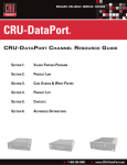
1
500 A Huntmar Park Drive
ASTi
Telestra v2.4 User Guide
HLA Communications Environment
Remote Management System
High-Frequency (HF) Radio Server
Automatic Link Establishment (ALE) Server
Satellite Communications Server
Panel State Machine Runtime Environment
Terrain Server
Document: DOC-01-TELS-UG-2
Advanced Simulation Technology inc.500A Huntmar Park Drive, Herndon, Virginia, 20170 USA
Revision L.1 (May 2007)
Product Name: Telestra
ASTi
ASTi Telestra User Guide
© Copyright ASTi 1999-2007.
Restricted Rights: Use, duplication, or disclosure by the Government is subject to restrictions as set forth in subparagraph (c)(1)(ii) of the Rights in Technical Data and Computer Software clause at DFARS 252.227-7013.
This material may be reproduced by or for the U.S. Government pursuant to the copyright license under the
clause at DFARS 252.227-7013 (1994).
ASTi
500-A Huntmar Park Drive
Herndon, VA 20170
TABLE OF CONTENTS
Chapter 1: Introduction . . . . . . . . . . . . . . . . . . . . . . . . . . . . . . . . . . . . . . 1
Remote Management System . . . . . . . . . . . . . . . . . . . . . . . . . . . . . . . . . . . . . . . . . . . . . . . . . 1
HLA Communications Environment . . . . . . . . . . . . . . . . . . . . . . . . . . . . . . . . . . . . . . . . . . . . 1
Model Documentation Tool . . . . . . . . . . . . . . . . . . . . . . . . . . . . . . . . . . . . . . . . . . . . . . . . . . . 1
HF Radio Propagation Server . . . . . . . . . . . . . . . . . . . . . . . . . . . . . . . . . . . . . . . . . . . . . . . . . 1
Automatic Link Establishment (ALE) Server . . . . . . . . . . . . . . . . . . . . . . . . . . . . . . . . . . . . . 2
Satellite Communications Server . . . . . . . . . . . . . . . . . . . . . . . . . . . . . . . . . . . . . . . . . . . . . . . 2
Panel State Machine Runtime Environment . . . . . . . . . . . . . . . . . . . . . . . . . . . . . . . . . . . . . . 2
Terrain Server . . . . . . . . . . . . . . . . . . . . . . . . . . . . . . . . . . . . . . . . . . . . . . . . . . . . . . . . . . . . . 2
Chapter 2: System Installation . . . . . . . . . . . . . . . . . . . . . . . . . . . . . . . . 3
Figure 1: Telestra Connections Diagram . . . . . . . . . . . . . . . . . . . . . . . . . . . . . . . . . . . . . . . . . . . . 3
Network Interfaces . . . . . . . . . . . . . . . . . . . . . . . . . . . . . . . . . . . . . . . . . . . . . . . . . . . . . . . . . . 3
Table 1: Telestra Network Interface Roles . . . . . . . . . . . . . . . . . . . . . . . . . . . . . . . . . . . . . . . . . . . 3
Figure 2a-d: Ethernet Port Physical Locations: 1U Telestra Chassis . . . . . . . . . . . . . . . . . . . . . . 4
Figure 2e: Ethernet Port Physical Locations: 2U Telestra Chassis . . . . . . . . . . . . . . . . . . . . . . . . 5
Identifying your System . . . . . . . . . . . . . . . . . . . . . . . . . . . . . . . . . . . . . . . . . . . . . . . . . . . . . . 5
Chapter 3: Starting and Stopping the Telestra System . . . . . . . . . . . . 6
Starting Telestra . . . . . . . . . . . . . . . . . . . . . . . . . . . . . . . . . . . . . . . . . . . . . . . . . . . . . . . . . . . . 6
System Shutdown . . . . . . . . . . . . . . . . . . . . . . . . . . . . . . . . . . . . . . . . . . . . . . . . . . . . . . . . . . 6
Chapter 4: System Accounts & Services . . . . . . . . . . . . . . . . . . . . . . . . 7
Telestra System Accounts . . . . . . . . . . . . . . . . . . . . . . . . . . . . . . . . . . . . . . . . . . . . . . . . . . . . 7
Table 2: Telestra System Accounts . . . . . . . . . . . . . . . . . . . . . . . . . . . . . . . . . . . . . . . . . . . . . . . . . 7
File Transfer Protocol (FTP) . . . . . . . . . . . . . . . . . . . . . . . . . . . . . . . . . . . . . . . . . . . . . . . . . . 7
Command Line Access . . . . . . . . . . . . . . . . . . . . . . . . . . . . . . . . . . . . . . . . . . . . . . . . . . . . . . 7
Secure Network Services . . . . . . . . . . . . . . . . . . . . . . . . . . . . . . . . . . . . . . . . . . . . . . . . . . . . . 7
Chapter 5: Initial Network Configuration . . . . . . . . . . . . . . . . . . . . . . . . 8
Default Network Settings . . . . . . . . . . . . . . . . . . . . . . . . . . . . . . . . . . . . . . . . . . . . . . . . . . . . . 8
Table 3: Default Network Settings. . . . . . . . . . . . . . . . . . . . . . . . . . . . . . . . . . . . . . . . . . . . . . . . . . 8
Telestra Configuration Utility . . . . . . . . . . . . . . . . . . . . . . . . . . . . . . . . . . . . . . . . . . . . . . . . . 9
Figure 3: Telestra Configuration Utility . . . . . . . . . . . . . . . . . . . . . . . . . . . . . . . . . . . . . . . . . . . . . 9
Figure 4: Telestra Settings Screen . . . . . . . . . . . . . . . . . . . . . . . . . . . . . . . . . . . . . . . . . . . . . . . . 10
Figure 5: Change IP Settings Screen . . . . . . . . . . . . . . . . . . . . . . . . . . . . . . . . . . . . . . . . . . . . . . 11
Chapter 6: Telestra RMS Web Interface . . . . . . . . . . . . . . . . . . . . . . . . 12
Browser Compatibility & System Configuration Tips . . . . . . . . . . . . . . . . . . . . . . . . . . . . . 12
Web Technology Security Issues . . . . . . . . . . . . . . . . . . . . . . . . . . . . . . . . . . . . . . . . . . . . . . 13
Pointing the Browser to RMS . . . . . . . . . . . . . . . . . . . . . . . . . . . . . . . . . . . . . . . . . . . . . . . . 15
Standard RMS Operation . . . . . . . . . . . . . . . . . . . . . . . . . . . . . . . . . . . . . . . . . . . . . . . . . . . . 15
System Login: Factory Default User ID & Password . . . . . . . . . . . . . . . . . . . . . . . . . . . . . . 16
i
Chapter 7: RMS Software & Operation . . . . . . . . . . . . . . . . . . . . . . . . 17
DACS System Requirements . . . . . . . . . . . . . . . . . . . . . . . . . . . . . . . . . . . . . . . . . . . . . . . . . 17
A Tour of the RMS Layout . . . . . . . . . . . . . . . . . . . . . . . . . . . . . . . . . . . . . . . . . . . . . . . . . . 23
Figure 6: RMS Frames Layout . . . . . . . . . . . . . . . . . . . . . . . . . . . . . . . . . . . . . . . . . . . . . . . . . . . 23
Figure 7: Sample RMS Screen Capture . . . . . . . . . . . . . . . . . . . . . . . . . . . . . . . . . . . . . . . . . . . . 28
RMS Setup Tutorial . . . . . . . . . . . . . . . . . . . . . . . . . . . . . . . . . . . . . . . . . . . . . . . . . . . . . . . . 29
Chapter 8: HLA Software & Operation . . . . . . . . . . . . . . . . . . . . . . . . . 60
DACS System Requirements . . . . . . . . . . . . . . . . . . . . . . . . . . . . . . . . . . . . . . . . . . . . . . . . . 60
HLA Setup Tutorial . . . . . . . . . . . . . . . . . . . . . . . . . . . . . . . . . . . . . . . . . . . . . . . . . . . . . . . . 62
The HLA Remote Control Interface . . . . . . . . . . . . . . . . . . . . . . . . . . . . . . . . . . . . . . . . . . . 78
Host Emulation Utility . . . . . . . . . . . . . . . . . . . . . . . . . . . . . . . . . . . . . . . . . . . . . . . . . . . . . . 79
Remote Control Interface Commands and Responses . . . . . . . . . . . . . . . . . . . . . . . . . . . . . . 80
Debugging the Remote Control Interface . . . . . . . . . . . . . . . . . . . . . . . . . . . . . . . . . . . . . . . 86
Table 4: Remote Control Debug Levels . . . . . . . . . . . . . . . . . . . . . . . . . . . . . . . . . . . . . . . . . . . . 86
HLA-Specific System File Structure . . . . . . . . . . . . . . . . . . . . . . . . . . . . . . . . . . . . . . . . . . . 87
Chapter 9: Using the Model Documentation Tool . . . . . . . . . . . . . . . . 88
Uploading an XML File . . . . . . . . . . . . . . . . . . . . . . . . . . . . . . . . . . . . . . . . . . . . . . . . . . . . . 88
Selecting an XML File Directly from a DACS . . . . . . . . . . . . . . . . . . . . . . . . . . . . . . . . . . . 89
The Document Information Screen . . . . . . . . . . . . . . . . . . . . . . . . . . . . . . . . . . . . . . . . . . . . 90
Chapter 10: HF Radio Propagation Server . . . . . . . . . . . . . . . . . . . . . 93
DACS System Requirements . . . . . . . . . . . . . . . . . . . . . . . . . . . . . . . . . . . . . . . . . . . . . . . . . 94
Figure 8: Page 3 of 9 of Model Builder’s Radio Object . . . . . . . . . . . . . . . . . . . . . . . . . . . . . . . . 96
HF Server Host Interface . . . . . . . . . . . . . . . . . . . . . . . . . . . . . . . . . . . . . . . . . . . . . . . . . . . . 97
HF Server Utilities in RMS . . . . . . . . . . . . . . . . . . . . . . . . . . . . . . . . . . . . . . . . . . . . . . . . . . 98
Chapter 11: ALE Server . . . . . . . . . . . . . . . . . . . . . . . . . . . . . . . . . . . . 101
Theory of Operation . . . . . . . . . . . . . . . . . . . . . . . . . . . . . . . . . . . . . . . . . . . . . . . . . . . . . . . 101
System Configuration . . . . . . . . . . . . . . . . . . . . . . . . . . . . . . . . . . . . . . . . . . . . . . . . . . . . . 102
ALE Server Utilities in RMS . . . . . . . . . . . . . . . . . . . . . . . . . . . . . . . . . . . . . . . . . . . . . . . . 103
ALE Server Host Interface . . . . . . . . . . . . . . . . . . . . . . . . . . . . . . . . . . . . . . . . . . . . . . . . . . 103
Chapter 12: Satellite Communications Server . . . . . . . . . . . . . . . . . 104
Theory of Operation . . . . . . . . . . . . . . . . . . . . . . . . . . . . . . . . . . . . . . . . . . . . . . . . . . . . . . . 105
Figure 9: Functional Flow Diagram, ASTi Simulated Satellite Communications System . . . . . 105
DACS System Requirements & Configuration . . . . . . . . . . . . . . . . . . . . . . . . . . . . . . . . . . 108
Figure 10: ASTi Radio Object, Page 2 of 9: Frequency Settings . . . . . . . . . . . . . . . . . . . . . . . . 109
Figure 11: ASTi Radio Object, Page 3 of 9: Mode Settings . . . . . . . . . . . . . . . . . . . . . . . . . . . . 110
Table 5: ASTi Satellite Simulation Modes, Summary . . . . . . . . . . . . . . . . . . . . . . . . . . . . . . . . . 111
Satcom Server Utilities in RMS . . . . . . . . . . . . . . . . . . . . . . . . . . . . . . . . . . . . . . . . . . . . . . 112
Satellite Tx/Rx Example . . . . . . . . . . . . . . . . . . . . . . . . . . . . . . . . . . . . . . . . . . . . . . . . . . . 114
ii
Chapter 13: Terrain Server . . . . . . . . . . . . . . . . . . . . . . . . . . . . . . . . . 115
Theory of Operation . . . . . . . . . . . . . . . . . . . . . . . . . . . . . . . . . . . . . . . . . . . . . . . . . . . . . . . 115
Figure 12: Functional Flow Diagram, ASTi Terrain Server . . . . . . . . . . . . . . . . . . . . . . . . . . . 116
DACS System Requirements and Configuration . . . . . . . . . . . . . . . . . . . . . . . . . . . . . . . . . 117
Terrain Status Window . . . . . . . . . . . . . . . . . . . . . . . . . . . . . . . . . . . . . . . . . . . . . . . . . . . . 119
Figure 13: Model Builder Terrain Occulting Status Window . . . . . . . . . . . . . . . . . . . . . . . . . . . 119
Terrain Server Utilities in RMS . . . . . . . . . . . . . . . . . . . . . . . . . . . . . . . . . . . . . . . . . . . . . . 120
Chapter 14: Panel State Machine Runtime Environment . . . . . . . . . 133
Figure 14: RMS State Machine Monitor screen . . . . . . . . . . . . . . . . . . . . . . . . . . . . . . . . . . . . . 134
Theory of Operation . . . . . . . . . . . . . . . . . . . . . . . . . . . . . . . . . . . . . . . . . . . . . . . . . . . . . . . 135
DACS System Requirements & Configuration . . . . . . . . . . . . . . . . . . . . . . . . . . . . . . . . . . 136
State Machine Utilities in RMS . . . . . . . . . . . . . . . . . . . . . . . . . . . . . . . . . . . . . . . . . . . . . . 137
Chapter 15: USB I/O Device Software Configuration . . . . . . . . . . . . 144
Software Configuration . . . . . . . . . . . . . . . . . . . . . . . . . . . . . . . . . . . . . . . . . . . . . . . . . . . . 144
Chapter 16: Telestra Configuration Parameters . . . . . . . . . . . . . . . . 146
Basic Settings . . . . . . . . . . . . . . . . . . . . . . . . . . . . . . . . . . . . . . . . . . . . . . . . . . . . . . . . . . . . 147
DACS Settings . . . . . . . . . . . . . . . . . . . . . . . . . . . . . . . . . . . . . . . . . . . . . . . . . . . . . . . . . . . 148
DACS Routing Settings . . . . . . . . . . . . . . . . . . . . . . . . . . . . . . . . . . . . . . . . . . . . . . . . . . . . 150
Network Settings . . . . . . . . . . . . . . . . . . . . . . . . . . . . . . . . . . . . . . . . . . . . . . . . . . . . . . . . . 151
HLA Settings . . . . . . . . . . . . . . . . . . . . . . . . . . . . . . . . . . . . . . . . . . . . . . . . . . . . . . . . . . . . 155
Satellite Communications Server Settings . . . . . . . . . . . . . . . . . . . . . . . . . . . . . . . . . . . . . . 158
Time (NTP) Server Settings . . . . . . . . . . . . . . . . . . . . . . . . . . . . . . . . . . . . . . . . . . . . . . . . . 162
Chapter 17: Procedural Warnings . . . . . . . . . . . . . . . . . . . . . . . . . . . 164
General Guidelines . . . . . . . . . . . . . . . . . . . . . . . . . . . . . . . . . . . . . . . . . . . . . . . . . . . . . . . . 164
Uploading Files . . . . . . . . . . . . . . . . . . . . . . . . . . . . . . . . . . . . . . . . . . . . . . . . . . . . . . . . . . 165
DACS Backup . . . . . . . . . . . . . . . . . . . . . . . . . . . . . . . . . . . . . . . . . . . . . . . . . . . . . . . . . . . 166
DACS Restoration . . . . . . . . . . . . . . . . . . . . . . . . . . . . . . . . . . . . . . . . . . . . . . . . . . . . . . . . 167
Changing DACS “config.sys” File . . . . . . . . . . . . . . . . . . . . . . . . . . . . . . . . . . . . . . . . . . . 167
Model Builder Virtual Screen Utility . . . . . . . . . . . . . . . . . . . . . . . . . . . . . . . . . . . . . . . . . 168
Chapter 18: Troubleshooting . . . . . . . . . . . . . . . . . . . . . . . . . . . . . . . 169
Troubleshooting RMS . . . . . . . . . . . . . . . . . . . . . . . . . . . . . . . . . . . . . . . . . . . . . . . . . . . . . 169
Troubleshooting HLA Error Messages . . . . . . . . . . . . . . . . . . . . . . . . . . . . . . . . . . . . . . . . 174
Troubleshooting the HF Server . . . . . . . . . . . . . . . . . . . . . . . . . . . . . . . . . . . . . . . . . . . . . . 175
Figure 15: Accessing the Terrain Occulting Status Window in Model Builder . . . . . . . . . . . . .
Figure 16: Model Builder Terrain Occulting Status Window . . . . . . . . . . . . . . . . . . . . . . . . . . .
Figure 17: Accessing the DIS Network Local RX/TX Paths List in Model Builder . . . . . . . . . .
Figure 18: Model Builder DIS Network Local RX/TX Paths List . . . . . . . . . . . . . . . . . . . . . . . .
Figure 19: Model Builder Path Inspection Screen . . . . . . . . . . . . . . . . . . . . . . . . . . . . . . . . . . .
175
176
177
178
178
Troubleshooting the Satcom Server . . . . . . . . . . . . . . . . . . . . . . . . . . . . . . . . . . . . . . . . . . . 180
Troubleshooting State Machines . . . . . . . . . . . . . . . . . . . . . . . . . . . . . . . . . . . . . . . . . . . . . 185
iii
Appendix A: Example Network Topologies . . . . . . . . . . . . . . . . . . . . 187
Figure 20: HLA/RMS Network Topology . . . . . . . . . . . . . . . . . . . . . . . . . . . . . . . . . . . . . . . . . . 187
Figure 21: Recommended Non-HLA Network Topology . . . . . . . . . . . . . . . . . . . . . . . . . . . . . . 188
Example RMS-Specific Network Configuration . . . . . . . . . . . . . . . . . . . . . . . . . . . . . . . . . 188
Figure 22: Example Installation Layout . . . . . . . . . . . . . . . . . . . . . . . . . . . . . . . . . . . . . . . . . . . 189
Appendix B: Telestra Version Compatibilities . . . . . . . . . . . . . . . . . 191
Table 6: Telestra Compatibility. . . . . . . . . . . . . . . . . . . . . . . . . . . . . . . . . . . . . . . . . . . . . . . . . . 192
Telestra Compatibility Table Notes . . . . . . . . . . . . . . . . . . . . . . . . . . . . . . . . . . . . . . . . . . . 192
Appendix C: HF Server ICD . . . . . . . . . . . . . . . . . . . . . . . . . . . . . . . . . 194
Input Control Data Types . . . . . . . . . . . . . . . . . . . . . . . . . . . . . . . . . . . . . . . . . . . . . . . . . . . 194
Table 7: HF Server ICD . . . . . . . . . . . . . . . . . . . . . . . . . . . . . . . . . . . . . . . . . . . . . . . . . . . . . . . 194
Appendix D: ALE Server ICD . . . . . . . . . . . . . . . . . . . . . . . . . . . . . . . 195
Introduction . . . . . . . . . . . . . . . . . . . . . . . . . . . . . . . . . . . . . . . . . . . . . . . . . . . . . . . . . . . . . 195
Input Control Data Types . . . . . . . . . . . . . . . . . . . . . . . . . . . . . . . . . . . . . . . . . . . . . . . . . . . 195
Output Control Data Types . . . . . . . . . . . . . . . . . . . . . . . . . . . . . . . . . . . . . . . . . . . . . . . . . 195
Initialize/Set Scan List Type Message (Type=1) . . . . . . . . . . . . . . . . . . . . . . . . . . . . . . . . . 196
Table 8: ALE Server ICD: Initialize/Set Scan List . . . . . . . . . . . . . . . . . . . . . . . . . . . . . . . . . . . 196
ALE TX Initiate (ALL CALL) Type Message (Type=2) . . . . . . . . . . . . . . . . . . . . . . . . . . 196
Table 9: ALE Server ICD: ALE Tx Initiate (ALL CALL) . . . . . . . . . . . . . . . . . . . . . . . . . . . . . . 196
ALE TX Response Message (Type=4, from ALE Server to Host) . . . . . . . . . . . . . . . . . . . 197
ALE Server Sync Type Message (Type=5) . . . . . . . . . . . . . . . . . . . . . . . . . . . . . . . . . . . . . 198
Table 11: ALE Server ICD: ALE Server Sync Message . . . . . . . . . . . . . . . . . . . . . . . . . . . . . . . 198
Appendix E: Satellite Communications Server ICD . . . . . . . . . . . . . 199
Input Control Data Types . . . . . . . . . . . . . . . . . . . . . . . . . . . . . . . . . . . . . . . . . . . . . . . . . . . 199
Table 12: Satcom Server ICD . . . . . . . . . . . . . . . . . . . . . . . . . . . . . . . . . . . . . . . . . . . . . . . . . . . 199
Notes & Errata . . . . . . . . . . . . . . . . . . . . . . . . . . . . . . . . . . . . . . . . . . . 200
Telestra Version 2.4-5, January, 2006 . . . . . . . . . . . . . . . . . . . . . . . . . . . . . . . . . . . . . . . . . 200
Documentation Update, April 6, 2005 . . . . . . . . . . . . . . . . . . . . . . . . . . . . . . . . . . . . . . . . . 200
Telestra version 2.4-4, March 2005 . . . . . . . . . . . . . . . . . . . . . . . . . . . . . . . . . . . . . . . . . . . 200
Documentation Update, January 21, 2005 . . . . . . . . . . . . . . . . . . . . . . . . . . . . . . . . . . . . . . 200
Telestra version 2.4-3, August 2004 . . . . . . . . . . . . . . . . . . . . . . . . . . . . . . . . . . . . . . . . . . 201
Telestra version 2.4, January 2004 . . . . . . . . . . . . . . . . . . . . . . . . . . . . . . . . . . . . . . . . . . . 201
Telestra version 2.3, September 2003 . . . . . . . . . . . . . . . . . . . . . . . . . . . . . . . . . . . . . . . . . 202
Documentation Update, May 2003 . . . . . . . . . . . . . . . . . . . . . . . . . . . . . . . . . . . . . . . . . . . 202
Telestra version 2.2, November 2002 . . . . . . . . . . . . . . . . . . . . . . . . . . . . . . . . . . . . . . . . . 202
Telestra version 2.1, September 2002 . . . . . . . . . . . . . . . . . . . . . . . . . . . . . . . . . . . . . . . . . 203
Table 9: Changes to the Telestra Configuration File for DACS Server Routing . . . . . . . . . . . . 203
Older Release Notes & Errata . . . . . . . . . . . . . . . . . . . . . . . . . . . . . . . . . . . . . . . . . . . . . . . 204
Warranty and Repairs . . . . . . . . . . . . . . . . . . . . . . . . . . . . . . . . . . . . . 205
Warranty Information . . . . . . . . . . . . . . . . . . . . . . . . . . . . . . . . . . . . . . . . . . . . . . . . . . . . . 205
Repairs and Returns . . . . . . . . . . . . . . . . . . . . . . . . . . . . . . . . . . . . . . . . . . . . . . . . . . . . . . . 205
Disclaimer and Warnings . . . . . . . . . . . . . . . . . . . . . . . . . . . . . . . . . . . . . . . . . . . . . . . . . . . 206
iv
ASTi Telestra User Guide (Ver. 2, Rev. L.1)
Chapter 1: Introduction
ASTi's Telestra product line is a Linux-based platform that hosts a variety of ASTi software applications. These include the Remote Management System (RMS) software, multicast router software, HLA Communications Environment software, and Model Documentation Tool. Telestra
version 2.2 features support for ASTi’s high-frequency (HF) radio propagation server, satellite
communications server, radio panel state machine modeling framework, and terrain server, with
the web-based RMS interface serving as the portal to all other applications and services.
ASTi documentation is also available for download from ASTi’s website at:
http://www.asti-usa.com/support/document
Remote Management System
The Telestra Remote Management System (RMS) is a specialized web server that provides complete sight and control of all ASTi devices on the simulation network, ranging from stand-alone to
multi-site, exercise-wide network configurations. Users can configure the HLA Communications
Environment, multicast routing capability, and individual DACS systems using a standard web
browser from anywhere on the network. Further, RMS offers a familiar point-and-click “web
page” interface for controlling ASTi resources, status checking, file and network management,
and DACS model documentation generation.
HLA Communications Environment
For High Level Architecture (HLA) applications, Telestra comes with ASTi’s federate software
and various test, support, and debug tools pre-installed. The federate software is designed to be
compatible with various RTIs. Please consult Appendix B: Telestra Compatibility for a listing of
which combinations of RTI versions, SOM versions, and Telestra versions have been tested by
ASTi.
The HLA sections of this guide assume the user has a basic understanding of the HLA, and should
be familiar with such terms as federate, federation, RTI, etc. It also assumes a basic familiarity
with UNIX, such as accounts, passwords, basic commands, etc.
Model Documentation Tool
Each time a user saves a model in ASTi’s Model Builder software, it automatically generates an
XML file describing that model’s structure and its constituent objects. Through the RMS interface, users can browse a DACS’ hard disk and select any model’s XML file for PDF document
generation. Alternately, users can upload any Model Builder XML file directly to the Telestra system as the source for document generation.
The Model Documentation Tool requires XML files from Model Builder 4.09 and later.
HF Radio Propagation Server
The ASTi HF Server provides real-time, high-fidelity modeling of HF radios using the Model
Builder virtual radio environment. The HF Server computes propagation effects between virtual
radios, taking into account such things as transmitter-receiver global position, season, time of day
(day-night terminator), and solar activity.
Copyright © 1999-2006 Advanced Simulation Technology inc.
1
ASTi Telestra User Guide (Ver. 2, Rev. L.1)
Automatic Link Establishment (ALE) Server
The ASTi ALE Server is used in conjunction with the ASTi HF Radio Propagation Server to realistically simulate the functionality of modern HF Automatic Link Establishment radios. The ALE
Server allows a host computer to initiate the server with lists of radios and scan frequencies, and
perform basic simulated ALE functions, such as soundings and calls. The ALE Server will typically perform a propagation analysis, and return a list of radio IDs and realistic Link Quality
Assessment (LQA) numbers, which depend on radio and environmental factors.
Satellite Communications Server
ASTi’s Telestra Satcom Server software, in combination with ASTi simulated radio objects,
extends the simulated radio environment to include the effects of voice communications over satellite links. Satellite communication effects include:
• End-to-end voice delays of up to several seconds for each link
• Support for up to 255 simultaneous links
• Able to serve satellite effects to multiple ASTi radio models working in multiple exercises
• Many satellite systems can be simultaneously modeled, each with realistic characteristic
effects. Simulated modes include: 5 KHz Dedicated, 25 KHz Dedicated, 5 KHz DASA, 25
KHz DC DASA, 5 KHz DAMA, 25 KHz AC DAMA, 25 KHz DC DAMA
• Separate uplink and downlink frequencies are modeled, providing the ability to simulate
half- or full-duplex communications channels
• The Satcom Server supports existing ASTi radio simulation features, such as crypto effects
Panel State Machine Runtime Environment
ASTi’s Panel State Machine Runtime Environment (PSMRE) represents the phase 1 launch of the
next-generation ASTi Model Builder Visual (MBV) software product. Utilizing a highly-innovative distributed synchronous realtime operating system, MBV opens the door to a vastly flexible
modeling environment. Running on the ASTi Telestra processing platform, the PSMRE provides
simulation modeling to drive “real” communication control panels. The PSMRE also controls the
routing and processing of data between panels, DACS systems, and the simulation host computer.
The runtime environment allows ASTi-developed state machines to be loaded and run, with
administration and functional visibility of system operation via RMS. All maintenance and support operations are handled through the RMS web-browser interface, avoiding the need for complex and specialized software skills.
Terrain Server
ASTi’s Terrain Server software applies occulting and degradation effects to communication paths
in the Model Builder radio environment. The Terrain Server interacts with Model Builder via
Model Builder’s existing terrain database interface, and can support all transmitter/receiver pairs
on the network. Telestra’s RMS web-browser interface also provides a terrain server poll function,
including visual representation of the terrain profile between two world positions.
2
Copyright © 1999-2006 Advanced Simulation Technology inc.
ASTi Telestra User Guide (Ver. 2, Rev. L.1)
Chapter 2: System Installation
After unpacking the ASTi Telestra unit, connect power, network, keyboard and monitor to the system as described in Figure 1.
Note: As technology evolves, the Telestra chassis will continue to change.
Look for these objects on the rear of the chassis, and connect as appropriate.
Power Cord In
To chassis
To wall
May not be present on all systems
Main Power Switch
Video Output
Connects to monitor's 15-pin D connector
Keyboard
PS/2 connection, may not be purple in color
Each system will have three (3) labeled jacks
x3
Ethernet Jack
RJ-45 connection
To network
Figure 1: Telestra Connections Diagram
Make sure the main power switch on the rear of CD-ROM-equipped Telestra systems is switched
on. Systems without built-in CD-ROM drives have only one power switch on the front of the
chassis.
Network Interfaces
Each Telestra platform has three ethernet connections. The physical location and function of each
of these connections varies, based on the hardware installed by ASTi prior to shipment. See Figures 2a-2e for more information. In any HLA application, each ethernet port must be connected to
a specific network. For installations where the HLA Communications Environment will not be
used, ASTi recommends using the Telestra system’s eth0 interface to access RMS over the network. Check ASTi Application Note 48, “Telestra Networking Concepts” for complete details.
See also Appendix A of this document for example network topologies.
Interface
eth0
eth1
eth2
HLA Role
Connects to HLA network
Connects to DACS network
Connects to Host Control network
RMS Role
Primary network connection (recommended)
Alternate network connection (not recommended)
Alternate network connection (not recommended)
Table 1: Telestra Network Interface Roles
Copyright © 1999-2006 Advanced Simulation Technology inc.
3
ASTi Telestra User Guide (Ver. 2, Rev. L.1)
Figure 2a. Ethernet locations on 1st gen. 1U Telestra chassis, no built-in CD-ROM
onboard
eth2
eth1
eth0
Host
DACS
HLA/RMS
Figure 2b. Ethernet locations on 2nd gen. 1U Telestra chassis, built-in CD-ROM
onboard
eth2
eth1
Host
DACS HLA/RMS
eth0
Figure 2c. Ethernet locations on 3rd gen. 1U Telestra chassis, built-in CD-ROM
Video
onboard
COM
eth2
eth0
eth1
Host
HLA/RMS
DACS
Figure 2d. Ethernet locations on 4th gen. 1U Telestra chassis, built-in CD-ROM
COM
onboard
Video
eth0
eth2
eth1
HLA/RMS
Host
DACS
Figure 2a-d: Ethernet Port Physical Locations: 1U Telestra Chassis
Note the difference in location of the video connector relative to the onboard ethernet port in
3rd and 4th generation Telestra chassis.
4
Copyright © 1999-2006 Advanced Simulation Technology inc.
ASTi Telestra User Guide (Ver. 2, Rev. L.1)
onboard
Network Interfaces
See chassis label for ethernet assignments
Figure 2e: Ethernet Port Physical Locations: 2U Telestra Chassis
Telestra systems arrive with all necessary software pre-loaded. To rebuild the system’s hard disk,
please see the Telestra Cold Start Procedure (DOC-01-TELS-CS-2). Turn on the Telestra system
via the power switch on the front of the chassis. The system will then boot into the Linux operating system.
Identifying your System
Depending on the system requirements there are various hard drive options used in the Telestra.
To identify your hard drive look for a part number on your system on the bottom of the carrier.
For Telestras with the Parallel IDE hard drive the part number on the bottom of the carrier is
DE75i-CA100/B. The ASTi part number on top is HD3-TL-A-R. This part number will only
appear on the drive if it is ordered as a spare drive, ie. This label is not installed on full systems
when they are initially shipped.
For Telestras with the SATA (Serial ATA) hard drive the part number on the bottom of the carrier
is S20J102. The ASTi part number installed on the top of the carrier every time is HD3-TL3-A-R.
Copyright © 1999-2006 Advanced Simulation Technology inc.
5
ASTi Telestra User Guide (Ver. 2, Rev. L.1)
Chapter 3: Starting and Stopping the Telestra System
Telestra runs the Linux operating system, and must be started—and more importantly shut
down—in the correct manner.
Starting Telestra
To start the unit, apply power via the front mounted on/off switch. The unit will boot-up and run
the Telestra software as background processes.
The user may log into the system and edit files from virtual consoles 2, 4, 5, or 6; console 1 is
used for the Telestra Configuration Utility (see Chapter 5: Initial Network Configuration), and
console 3 is reserved for the Model Builder Virtual Screens utility (see the RMS Setup Tutorial in
Chapter 7).
To switch to a particular console, press and hold the ALT key, and then press the corresponding
function key (F1 through F6). For example, the user may switch to the second console by pressing
ALT+F2.
In versions 1.6 and later, the Telestra federate software runs as a background process and may be
accessed only through the remote control interface. The Telestra system comes with a host emulator utility to allow the user to test the remote interface on Telestra. Chapter 8 provides detailed
information on the remote control interface and the host emulator utility.
System Shutdown
Local
The system can be rebooted and shutdown by selecting the “Reboot” or “Shutdown” button in the
Telestra Configuration Utility (see Chapter 5).
Alternately, the Linux command “shutdown -h now” may be entered from a console screen
to power down the system. The user must log in as “root” in order to use this command.
Wait until the screen display reads “Power down” before turning the power switch off.
Remote
The system can be rebooted and shutdown via the RMS web interface, through links in the Management section. It is also possible to shutdown and reboot the system via remote control over the
network. See Chapter 8 for more details on remote control of Telestra.
6
Copyright © 1999-2006 Advanced Simulation Technology inc.
ASTi Telestra User Guide (Ver. 2, Rev. L.1)
Chapter 4: System Accounts & Services
Telestra System Accounts
User Account
ftpuser
hlauser
rmsuser
Account Type
Linux system
Linux system
RMS webserver
Password
astirules
HLA!now!
astirules
Change Password?
no
yes (as hlauser)
yes (only in RMS)
Login
no
yes
no
Remote Login
no
yes
no
FTP
yes
yes
no
Table 2: Telestra System Accounts
Note that “rmsuser” is not a Linux system user account, like the others. All user account logins
and passwords are case-sensitive.
File Transfer Protocol (FTP)
Telestra systems support standard FTP for downloading DACS backup files, or uploading files for
DACS restoration. Telestra does not support anonymous FTP. Users should login to FTP as
“ftpuser”; this will put you into the /home/ftp/ftpuser directory. Simply change into
the “MBBackup” sub-directory (/home/ftp/ftpuser/MBBackup) to upload or download
files. Note this backup directory is also available at /home/MBBackup.
The “hlauser” account may also access Telestra via FTP.
Command Line Access
Users can access the Linux system command line by logging in directly (monitor and keyboard
connection to Telestra required), or remotely using the “ssh” network service. Local login
prompts can be found on Linux virtual consoles 2, 4, 5, or 6; console 1 is used for the Telestra
Configuration Utility, and console 3 is reserved for the Model Builder Virtual Screens utility. To
switch to a particular console, press the <ALT> key and the corresponding function key. For
example, the user may switch to the second console by pressing ALT+F2. Users should login as
“hlauser” to access the HLA Communications Environment’s host emulator software.
Altering the Telestra system from the command line can result in the system becoming unstable
or unusable. Completely rebuilding the hard drive through Cold Start is the only path to recovery. All prior changes to the system will be lost upon Cold Start.
To change the password for the “hlauser” account, log into the system using that account and
type “passwd” followed by the [Enter] key; then follow the directions printed on the screen.
Changing the password for “rmsuser” is detailed in Chapter 7.
DO NOT lose your passwords!
Secure Network Services
Telestra allows remote shell access via the “ssh” network service, but not “telnet”. In addition
to standard FTP access, Telestra also supports secure file transfer through the “sftp” client. See
your network administrator for more information.
Copyright © 1999-2006 Advanced Simulation Technology inc.
7
ASTi Telestra User Guide (Ver. 2, Rev. L.1)
Chapter 5: Initial Network Configuration
Default Network Settings
After initial software installation or system cold start, Telestra ethernet interface eth0 tries to
obtain a network IP address and subnet mask using DHCP. In order to obtain these network settings, a DHCP server must exist on the network intended for use by eth0. If Telestra cannot contact a DHCP server using eth0, it will assign a meaningless IP address of 0.0.0.0 to that interface.
Telestra’s other two ethernet interfaces are assigned default IP addresses and subnet masks. Refer
to Figures 2a-2f for the physical locations of the ethernet ports.
Interface
eth0
eth1
eth2
Default IP Address
via DHCP or 0.0.0.0
192.168.100.254
20.1.1.1
Default Subnet Mask
via DHCP or none
255.255.255.0
255.0.0.0
Table 3: Default Network Settings
If you do not wish to use DHCP to configure eth0 (or if the network does not have a DHCP
server), use the Telestra Configuration Utility to manually specify its IP address, subnet mask and
gateway IP. This will change eth0’s operational mode from “DHCP” to “fixed”.
After initial software installation or cold start, any ethernet interface can be configured manually
(“fixed” mode), or toggled to use DHCP to obtain its proper network configuration at any time.
This is done through the Configuration section of RMS.
For applications using HLA, all three interfaces must be configured with valid settings for their
particular network, according to their roles displayed in Table 1. For non-HLA applications, only
interface eth0 requires manual configuration.
Ask your network administrator for valid IP addresses and subnet masks for the networks where
Telestra will be integrated.
The procedure outlined in the “Telestra Configuration Utility” section is only required after initial
system installation or system cold start, and requires a keyboard and monitor be connected
directly to the Telestra chassis.
After initial configuration of interface eth0 (if not using DHCP), users must use the RMS web
interface to change settings for Telestra’s ethernet ports.
See ASTi Application Note 48: “Telestra Networking Concepts” (http://www.asti-usa.com/) for
the latest detailed information regarding integrating Telestra with your IP network.
8
Copyright © 1999-2006 Advanced Simulation Technology inc.
ASTi Telestra User Guide (Ver. 2, Rev. L.1)
Telestra Configuration Utility
Following system boot, the Telestra Configuration Utility screen will be displayed, as shown in
Figure 3 below.
Figure 3: Telestra Configuration Utility
Press the <TAB> key to move between elements (the current selection will be highlighted), or
hold down the <ALT> key, and press <TAB> to reverse the toggle order.
NOTE: The Telestra system can be restarted or shut down from this screen, although these options
are also available from the RMS web interface after initial network configuration.
Highlight the “Settings” option and press the <SPACE> bar or <ENTER> key to view the system’s current IP address, network gateway, and subnet mask (netmask) settings. An example is
shown in Figure 4.
Copyright © 1999-2006 Advanced Simulation Technology inc.
9
ASTi Telestra User Guide (Ver. 2, Rev. L.1)
Figure 4: Telestra Settings Screen
Immediately after initial system installation or cold start, these settings represent eth0 information
obtained by a DHCP server on the network, or will show an IP address of 0.0.0.0 with no subnet
mask or gateway IP.
Press the <SPACE> bar or <ENTER> key to select “OK”, or press the <ESC> key to return to the
main menu.
From the main screen (Figure 3 above), <TAB> or <ALT>+<TAB> to highlight the “Setup” element, and press the <SPACE> bar or <ENTER> key. This will display the “Change IP Settings”
screen, shown in Figure 5.
10
Copyright © 1999-2006 Advanced Simulation Technology inc.
ASTi Telestra User Guide (Ver. 2, Rev. L.1)
Figure 5: Change IP Settings Screen
Note that this will only affect settings for ethernet card eth0. To change settings for eth1 or eth2,
you must use the RMS web interface. Specifying network information on this screen will change
eth0’s operational mode from “DHCP” to “fixed”.
Specify the desired IP address, netmask, and gateway for the simulation network, pressing the
<ENTER> key after each element. If you are unsure of these settings, contact your network
administrator for more information. Use the <TAB> key to highlight “OK”, and press the
<SPACE> bar or <ENTER> to write the settings to Telestra’s hard disk; the system will then
restart its network software. Afterward, RMS can be accessed via its web-browser interface.
Copyright © 1999-2006 Advanced Simulation Technology inc.
11
ASTi Telestra User Guide (Ver. 2, Rev. L.1)
Chapter 6: Telestra RMS Web Interface
After Telestra’s eth0 interface is configured to the proper network settings, the system can be
accessed via any standard web browser on that network through the RMS web interface.
Browser Compatibility & System Configuration Tips
ASTi has designed and extensively tested RMS on a number of different operating systems, using
various popular web browsers to ensure compatibility. RMS works best with the following:
• Netscape Navigator/Communicator
Versions 4.7 through 4.78 (see note below)
Linux (KDE or Gnome), Windows 95/98/2000/ME, MacOS 8 & 9
• Internet Explorer
Versions 4.5 & 5.x or higher
Windows 95/98/2000/ME, MacOS 8 & 9, OS X
NOTE: ASTi recommends against using the Mozilla web browser (or Mozilla-based browsers like
Netscape 6.0) on any platform, due to unsatisfactory JavaScript support. ASTi also recommends
against using the OmniWeb browser on OS X, due to issues with its caching mechanism.
Browser Settings
These are usually referred to as “Preferences” or “Internet Settings”.
In order to take full advantage of RMS’s features, you may have to change some of the settings for
your web browser. Many of these are default settings, but ASTi recommends that you verify or
configure your browser to perform the following functions:
• Automatically Load Images
• Enable Frames
• Enable JavaScript for web pages
(enabling JavaScript for email is unnecessary, not to mention dangerous)
• Enable Style Sheets
• Accept Cookies
(all cookies or those which are returned to originating servers)
• Disable Full Caching
(set the browser to “compare page in cache to page on network” every time)
Please refer to your browser’s documentation or help system for information regarding these settings.
If you are concerned about the information stored by RMS “cookies”, or the nature of JavaScript
code used by RMS, please consult the “Web Technology Security Issues” section on the next page
for more information.
Screen Resolution
RMS supports 640 x 480 and 800 x 600 screen resolutions. 1024 x 768 resolution or higher is recommended.
12
Copyright © 1999-2006 Advanced Simulation Technology inc.
ASTi Telestra User Guide (Ver. 2, Rev. L.1)
Web Technology Security Issues
The Telestra Remote Management System uses modern Internet client/server technology (like
cookies and JavaScript) to extend its functionality, and enhance the quality of features offered to
ASTi’s customers.
Unfortunately, due to less-than-well-meaning Internet users (and the media exposure their
exploits elicit), much of the Internet’s “general public” has rightfully become wary, if not completely paranoid, about these technologies. Here, ASTi will attempt to allay any concerns you may
have about the use of these technologies in RMS.
Cookies
What are “cookies”?
They are small bits of text that come from a web server, and are handled by your web browser.
There are two types of cookies: “session” and “persistent”.
“Session” cookies only live as long as your web browser program is running. When you close the
application, or shut down your computer, the information contained in the session cookie is then
lost. “Persistent” cookies are stored on your local computer’s hard disk, in a “cookie list”. The
information contained in persistent cookies will remain available to the web browser and web
server until it expires, or is deleted.
How does RMS use cookies?
There are only three ways that RMS employs cookie technology.
• Is this your first time?
When you first access an RMS server, the system checks to see if you’ve ever visited that
server before. If you have not, you are automatically transported to the “Getting Started”
section, and a persistent cookie is placed on your hard disk. The next time you visit the
RMS server using that same browser, the system by-passes sending you to this introductory section.
• Are you logged into the system?
The first time you attempt to access administrator-level information in the RMS system
(like the RMS Configuration section), you are asked to log in with a user ID and password.
Once you have successfully provided these two bits of information, a session cookie is
passed back to your browser from the RMS server, allowing you to access any administrator-level information without having to log in again. Please note: ASTi recommends shutting down your browser application when you’ve finished accessing an RMS server. This
will clear the session cookie, and RMS will force another log-in the next time someone
(even you) tries to access administrator-level information.
• Setting your “Automatic Refresh Rate” preference
The majority of web pages generated by the RMS server will automatically refresh themselves after a given period of time (our attempt to ensure that you get the most up-to-date
information). The first time you access an RMS server, a persistent cookie is placed on
your hard disk which specifies that the refresh rate is 300 seconds (5 minutes). After
you’ve logged into the system, you can change this setting in the “Preferences” section.
Copyright © 1999-2006 Advanced Simulation Technology inc.
13
ASTi Telestra User Guide (Ver. 2, Rev. L.1)
When you specify your preferred refresh rate (in seconds), the RMS server will replace the
previous cookie with another persistent cookie reflecting the new waiting period.
The two persistent cookies mentioned above are the only bits of information that RMS writes to
your computer’s hard disk, and are the only pieces of information that RMS can access on your
computer. No information whatsoever is transmitted to ASTi, or anywhere else.
JavaScript
What is “JavaScript”?
It is a simple programming language that extends a web browser’s capabilities beyond that which
is possible using only HTML (the standard language for generating web pages).
How does RMS use JavaScript?
There are only a few ways that RMS employs JavaScript.
• Launching Remote Windows
At times, RMS will open remote windows to keep information separate from the “main
window”. For example, when you access the online RMS Help system, a new window will
pop up containing the information you requested.
• Window & Frame Navigation
RMS uses JavaScript for simple operations like closing remote windows, and telling a certain frame in the main window to load a specific page.
• Pop-up Notes
In the RMS Servers frame, if you move your mouse pointer over any of the RMS icons, a
small note pops up to display some basic information about that server. This is also used in
the RMS and DACS menus to explain the various menu selections.
• Image Roll-Overs
JavaScript is also used to display different graphics when your mouse pointer moves over
certain images.
That’s it. There is NO JavaScript code in RMS that will attempt to access, change or manipulate
any information on your local computer at any time. Again, no information whatsoever is transmitted to ASTi, or anywhere else.
14
Copyright © 1999-2006 Advanced Simulation Technology inc.
ASTi Telestra User Guide (Ver. 2, Rev. L.1)
Pointing the Browser to RMS
In order to access RMS using a web browser, the computer you use must be on the same network
segment (LAN or WAN) as the RMS server itself. Contact your network administrator if you have
any questions.
Launch your web browser application. In the “Address” or “Location” field of the web browser’s
display, type:
http://xxx.xxx.xxx.xxx/
... where “xxx.xxx.xxx.xxx” is the IP address previously assigned to eth0 using the Telestra Configuration Utility.
If this is the first time you are accessing this particular RMS server with the computer and web
browser, RMS will automatically redirect you to the online “Getting Started” section. The “Getting Started” information is also included in this document.
If you have visited this RMS server before, then you will be taken directly to the standard display.
Standard RMS Operation
Most of the features available through RMS are reserved for authorized users, and system login
(User ID & Password) is required. System login is not required to:
• View the “Getting Started” presentation.
• View software version information.
• View RMS servers on the network & their basic information.
• View Installation and Contact information for RMS servers.
• Access the RMS Help system.
• View DACS systems, including:
Basic information
Model Builder version & credits
Running models
DSPs (not DSP-specific information or statistics)
If applicable, RIUs connected to DSPs (again, no specific information)
Everything else is administrator-level information, and requires system login.
Copyright © 1999-2006 Advanced Simulation Technology inc.
15
ASTi Telestra User Guide (Ver. 2, Rev. L.1)
System Login: Factory Default User ID & Password
The factory default user ID is: rmsuser
The user ID is case-sensitive, and you cannot change it.
The factory default password is: astirules
The password is also case-sensitive, but you can change it through RMS’s “Preferences” interface.
This procedure is outlined in Step 2 of the RMS Setup Tutorial.
Change your password! Since each RMS is shipped with the same default password, this affords
virtually no security for your system. Changing your login password immediately after installation will prevent the possibility of another RMS user accessing your system.
Remember your password! If you forget your new password, the only way to recover the system
(i.e., restore the factory default) is to reinstall the Telestra software via the Cold Start Procedure
(DOC-01-TELS-CS-2).
16
Copyright © 1999-2006 Advanced Simulation Technology inc.
ASTi Telestra User Guide (Ver. 2, Rev. L.1)
Chapter 7: RMS Software & Operation
DACS System Requirements
To enable a DACS system for remote management via RMS, a few DACS configuration procedures must first be followed.
Model Builder Software
DACS systems must be running Model Builder version 4.07 or higher for remote management,
although ASTi recommends running version 4.09 or higher.
DACS systems must be running in “Normal Mode - RMS control”, which is the default mode
(choice #1 in the DACS Startup Menu) for version 4.07 or higher on DACS system boot.
The introduction of remote DACS management has introduced some changes to the location of
various DACS configuration settings.
For use with RMS, we are concerned with two ASCII text files on the DACS where various settings can be specified:
• System Configuration File
This file is located at
C:\config.sys
and will hereafter be referred to as “config.sys” for clarity.
• Model Builder Application Configuration File
By default*, this file is located at
C:\mbuilder\user\models\default.cfg
and will hereafter be referred to as “default.cfg” for clarity.
*Although users can force the Model Builder software to load different Model Builder Application Configuration Files (all of which end in the “.cfg” file extension), that procedure will not be covered here, and all of
the changes presented here in reference to “default.cfg” also apply.
Also, for the sake of clarity, ethernet network interfaces will hereafter be referred to as “ethernet
cards”, since the majority of network parameters discussed in this section refer to hardware settings; “network interface” is a little too esoteric for this discussion.
Copyright © 1999-2006 Advanced Simulation Technology inc.
17
ASTi Telestra User Guide (Ver. 2, Rev. L.1)
The “default.cfg” File
To allow remote management, the “default.cfg” file loaded by the Model Builder software should
contain the following line:
CELL=ON
While you may find that the DACS system works with RMS without the “cell=on” directive, its
inclusion is still recommended, since later releases of Model Builder may have different default
settings.
Network settings that specify the following hardware parameters should be removed—or disabled by placing a semicolon (;) as the first character of the line—from the “default.cfg” file:
• Number of ethernet cards
• DIS/HLA ethernet card
• local IP address
• subnet mask
• gateway IP address
• Host ethernet card
• local IP address
• subnet mask
• gateway IP address
These settings should now be specified in the “config.sys” file, described in the next section.
IMPORTANT: Specifying the above hardware parameters in the “default.cfg” file will override
similar settings in the “config.sys” file.
All other network commands (port settings, DIS or HLA settings, etc.) should continue to reside
in “default.cfg”; this has not changed.
See Appendix A for an example installation.
18
Copyright © 1999-2006 Advanced Simulation Technology inc.
ASTi Telestra User Guide (Ver. 2, Rev. L.1)
The “config.sys” File
The hardware settings for the DACS system’s ethernet cards are now specified in the “config.sys”
file, along with a couple of other RMS-specific parameters. All of the settings listed here can be
changed via RMS’ web-interface. The following information explains the individual settings;
examples of properly configured “config.sys” files are included at the end of this section.
Other than the settings outlined here, DO NOT change any other lines in the “config.sys” file
unless specifically instructed by ASTi.
IMPORTANT: Do not use a space either before or after the “=” symbol in any of the “config.sys” commands. Commands should be typed exactly as shown in this document.
[menu]
This section of the “config.sys” file specifies which operational modes are available at DACS
startup.
DO NOT rename this “config.sys” heading.
DO NOT alter any of the lines under this heading, unless specifically instructed by ASTi.
Copyright © 1999-2006 Advanced Simulation Technology inc.
19
ASTi Telestra User Guide (Ver. 2, Rev. L.1)
[mbremote]
This section of the “config.sys” file specifies two RMS parameters: the IP address of the managing RMS server, and which DACS directory to load on system boot. DACS system ethernet
card settings are handled in the [common] section.
DO NOT rename this “config.sys” heading.
With the exception of those listed here, DO NOT alter any of the lines under this heading,
unless specifically instructed by ASTi.
SET REMOTE=<ipAddress>
<ipAddress> is the IP address of the RMS server that will manage this DACS system.
Changing this setting in the DACS “config.sys” file will not change the IP address of the RMS
server itself.
SET MODELS=<directory>
<directory> is the directory that the Model Builder software will load as its “current working
directory” on system boot. For example, if this is set to “USER”, Model Builder will start
using:
C:\mbuilder\user\models
as the current working directory, and will load the file:
C:\mbuilder\user\models\default.cfg
as the Model Builder Application Configuration File.
Performing a DACS restoration via RMS will increase the number of candidate directories for
this setting. For example, a DACS restoration performed using a backup file generated on January 3, 2001, will create a directory on the DACS hard disk named:
C:\mbuilder\03jan01
Setting the “SET MODELS=” parameter to “03JAN01” will cause Model Builder to start
using:
C:\mbuilder\03jan01\models
as the current working directory, and will load the file:
C:\mbuilder\03jan01\models\default.cfg
as the Model Builder Application Configuration File. Remember, ethernet card hardware settings specified in any “default.cfg” file will override similar settings in “config.sys”. After performing a DACS restoration, it is important to verify that settings in the new “default.cfg” do
not override the system’s “config.sys” file.
IMPORTANT: Do not use a space either before or after the “=” symbol in any of the “config.sys” commands. Commands should be typed exactly as shown in this document.
20
Copyright © 1999-2006 Advanced Simulation Technology inc.
ASTi Telestra User Guide (Ver. 2, Rev. L.1)
[common]
This section of “config.sys” handles the ethernet card hardware configurations for DACS systems. In Model Builder versions 4.07 and higher, the ethernet card settings listed below pertain to DACS systems running in remote mode (system default), and non-remote mode alike.
Each of the parameters listed below can be changed via RMS. Remember, similar settings in
the “default.cfg” file will override these “config.sys” parameters.
DO NOT rename this “config.sys” heading.
With the exception of those listed here, DO NOT alter any of the lines under this heading,
unless specifically instructed by ASTi.
For DACS Systems with One Ethernet Card:
SET LOCAL_IP=<ipAddress>
<ipAddress> is the IP address for the DACS system’s single ethernet card.
SET GATEWAY=<ipAddress>
<ipAddress> is the gateway IP address for the DACS system’s single ethernet card.
SET SUBNET_MASK=<netmask>
<netmask> is the subnet mask for the DACS system’s single ethernet card.
For DACS Systems with Two Ethernet Cards:
SET LOCAL_IP=<ipAddress1>,<ipAddress2>
<ipAddress1> is the IP address for the DACS system’s host ethernet card.
<ipAddress2> is the IP address for the system’s RMS/DIS/HLA ethernet card, and is the IP
address to configure in RMS for DACS discovery. Separate the two with a comma (,).
SET GATEWAY=<ipAddress1>,<ipAddress2>
<ipAddress1> is the gateway IP address for the DACS system’s host ethernet card.
<ipAddress2> is the gateway IP address for the system’s RMS/DIS/HLA ethernet card. Separate the two with a comma (,).
SET SUBNET_MASK=<netmask1>,<netmask2>
<netmask1> is the subnet mask for the DACS system’s host ethernet card.
<netmask2> is the subnet mask for the system’s RMS/DIS/HLA ethernet card. Separate the
two with a comma (,).
For the above settings, specifying only <ipAddress2>, such as “SET
LOCAL_IP=,<ipAddress2>” is not a valid “config.sys” command.
See Appendix A for an example installation.
IMPORTANT: Do not use a space either before or after the “=” or “,” symbols in any of the
“config.sys” commands. Commands should be typed exactly as shown in this document.
Copyright © 1999-2006 Advanced Simulation Technology inc.
21
ASTi Telestra User Guide (Ver. 2, Rev. L.1)
Single Ethernet DACS “config.sys” Example
In this example, the DACS system has one ethernet card.
[menu]
...
[mbremote]
SET SYSTEM=DEFAULT
SET MODELS=USER
SET REMOTE=192.168.100.101
...
[common]
SET LOCAL_IP=192.168.100.5
SET GATEWAY=192.168.100.100
SET SUBNET_MASK=255.255.255.0
...
Dual Ethernet DACS “config.sys” Example
In this example, the DACS system has two ethernet cards; one is the host ethernet card, the other
is the RMS/DIS/HLA ethernet card. In the sample file below, host card settings are in bold.
[menu]
...
[mbremote]
SET SYSTEM=DEFAULT
SET MODELS=USER
SET REMOTE=192.168.100.101
...
[common]
SET LOCAL_IP=192.168.212.51,192.168.100.5
SET GATEWAY=192.168.212.254,192.168.100.100
SET SUBNET_MASK=255.255.255.0,255.255.255.0
...
In this dual ethernet example, specify 192.168.100.5 as the DACS IP address in the RMS configuration utility. Otherwise, it will not be successfully discovered.
Other than the settings outlined here, DO NOT change any other lines in the “config.sys” file
unless specifically instructed to do so by ASTi.
IMPORTANT: Do not use a space either before or after the “=” or “,” symbols in any of the
“config.sys” commands. Commands should be typed exactly as shown in this document.
See Appendix A for an example installation.
22
Copyright © 1999-2006 Advanced Simulation Technology inc.
ASTi Telestra User Guide (Ver. 2, Rev. L.1)
A Tour of the RMS Layout
The RMS renders information in a number of various locations. These are represented by your
web browser as “frames”.
Figure 6: RMS Frames Layout
Header
This section of the layout features the stylish ASTi logo. Click on it to access ASTi’s website,
your source for the latest information about RMS and all of ASTi's products and services.
Footer
This lower-most section gives credit where credit is due, and also features a link to ASTi’s World
Wide Web site. Click on the RMS logo to access ASTi’s website.
Copyright © 1999-2006 Advanced Simulation Technology inc.
23
ASTi Telestra User Guide (Ver. 2, Rev. L.1)
RMS Server Frame
The left-most portion of your browser displays all of the RMS servers on your network (as per
their configuration settings). Move your mouse over any of the Telestra icons to view a pop-up
note containing information about that individual system. Click on the icon to access that server’s
RMS features.
Server Info Frame
This section details information about the RMS server that you are currently accessing. It includes
the RMS server description, trainer/facility/location information, and primary contact name,
phone number & email address, provided that this information has been configured by the RMS
server administrator.
RMS Menu Bar
This frame displays your available RMS server options. Clicking on one of the options in this
menu will result in the information being displayed in the “Telestra Info Frame”, outlined in red in
Figure 6. Clicking “Find DACS” in this menu will launch the DACS System Frame and DACS
Menu Bar.
24
Copyright © 1999-2006 Advanced Simulation Technology inc.
ASTi Telestra User Guide (Ver. 2, Rev. L.1)
Telestra Info Frame
This is the main frame in which Telestra information (selected from the RMS Menu Bar) will be
displayed. Here, the RMS Server Configuration screen is shown as an example.
Copyright © 1999-2006 Advanced Simulation Technology inc.
25
ASTi Telestra User Guide (Ver. 2, Rev. L.1)
DACS System Frame
This section displays the DACS systems that are assigned to the RMS server that you’re accessing. DACS systems are selected for RMS monitoring via the RMS Configuration section, where
their IP addresses are specified. As seen here, the system icons are accompanied by the “DACS
Name” and IP address, as set up in RMS Configuration.
DACS Menu Bar
This frame displays your available DACS system options. Clicking on one of the options in this
menu will result in the information being displayed in the “DACS Info Frame”, indicated in Figure 6.
26
Copyright © 1999-2006 Advanced Simulation Technology inc.
ASTi Telestra User Guide (Ver. 2, Rev. L.1)
DACS Info Frame
This is the main frame in which DACS information (selected from the DACS Menu Bar) will be
displayed. Here, the DACS System Backup screen is shown as an example.
All of the frames described here, when re-assembled, will look like Figure 7 below.
Copyright © 1999-2006 Advanced Simulation Technology inc.
27
ASTi Telestra User Guide (Ver. 2, Rev. L.1)
Figure 7: Sample RMS Screen Capture
28
Copyright © 1999-2006 Advanced Simulation Technology inc.
ASTi Telestra User Guide (Ver. 2, Rev. L.1)
RMS Setup Tutorial
This tutorial will take you through a total of 7 steps, demonstrating the following concepts:
• Step 1:
Uploading an Options File
• Step 2:
Logging into RMS
Changing the System Password
• Step 3:
Verifying the Network Setup
Working with the RMS Configuration Section
The Built-in RMS Help System
The RMS Configuration Buffer
• Step 4:
Adding DACS Systems to RMS
• Step 5:
Adding RIUs to the RMS Configuration
• Step 6:
Finding DACS Systems through RMS
Finding DACS DSP Cards
Adding RIUs “From the Field”
• Step 7:
Using the Model Builder Virtual Screen Utility
The built-in RMS Help System provides contextual discussions of key RMS concepts, and all
possible RMS Configuration File settings. Any time you see the RMS Help icon:
... click on it to launch a remote window containing more information about that particular section
or subject.
Information regarding setup and configuration of the HLA Communications Environment can be
found in the HLA Setup Tutorial.
Copyright © 1999-2006 Advanced Simulation Technology inc.
29
ASTi Telestra User Guide (Ver. 2, Rev. L.1)
STEP 1: Options File
For new systems, ASTi installs the appropriate Telestra Options File prior to shipment. If your
Telestra system does not yet have an Options File, the first thing you’ll want to do is give it one.
Already got one? Skip ahead to STEP 2.
In Telestra versions 2.2 and before, RMS will display an error message if it cannot locate your
Options File.
1. Click on the “Click here to upload a Telestra Options File” link. A new window will pop
up. If you're asked to enter a Username and Password, please follow the login procedure
outlined in Step 2.
Continue with upload instructions as outlined later in this step.
30
Copyright © 1999-2006 Advanced Simulation Technology inc.
ASTi Telestra User Guide (Ver. 2, Rev. L.1)
Starting in version 2.3, Telestra supports basic RMS functionality, even when no Options File is
present. RMS will not present the error message shown above. Instead, RMS will display a warning message at the bottom of system pages if it cannot find an Options file:
Without an Options File, however, the following Telestra services are disabled:
• HLA
• Multicast Router
• Satcom Server
• HF Radio Propagation Server
• ALE Server
• Terrain Database Server
To activate any of these services, you must upload the proper system-keyed Options File.
1. Click the “Mgmt.” icon in the RMS Menu bar.
2. When asked, provide the Username and Password to access the management interface.
Copyright © 1999-2006 Advanced Simulation Technology inc.
31
ASTi Telestra User Guide (Ver. 2, Rev. L.1)
3. On the main Management page, click the “Telestra Options File Management” link in the
table at the top.
4. On the “Telestra Options File Management” page, click the “Start Upload” image; the
upload window will then appear.
Continue with upload instructions as outlined later in this step.
32
Copyright © 1999-2006 Advanced Simulation Technology inc.
ASTi Telestra User Guide (Ver. 2, Rev. L.1)
This is the Options File Upload window:
1. In the new window, click the “Browse...” button. This will open a standard system dialog
box, asking you to locate the options file on your local computer (on the hard disk, or on a
disk inserted in your computer’s floppy drive).
2. If you can’t find the file you’re looking for, click “Cancel” in the dialog box, and click the
“Can’t Find It?” link in the upload window for help.
3. After locating the options file, click “OK” in the dialog box.
4. Click the “Upload File” button in the upload window.
5. The Telestra system will then have to restart some software, which will take about 30 seconds.
Note: Since Telestra v2.2, the Telestra Options File is no longer required to be named
“telestra.opt”. Telestra will accept any properly encrypted options file with an “.opt” or “.tgz” file
extension. Although the proper options file is loaded on any Telestra system prior to shipment,
you can contact ASTi to obtain an options file keyed to your system at any time.
Copyright © 1999-2006 Advanced Simulation Technology inc.
33
ASTi Telestra User Guide (Ver. 2, Rev. L.1)
STEP 2: Change the Password
The Telestra RMS comes with a pre-set User ID and Password. You can’t change the User ID, but
you’ll want to change the Password to something that’s easy for you to remember.
1. Click the “Preferences” link in the RMS Menu.
2. This part requires a log in, so supply the pre-set User ID and Password (defaults are at the
end of Chapter 6) in the slots provided in the pop-up window, and click “OK”.
3. Click on the “Change Login Password” link in the table.
34
Copyright © 1999-2006 Advanced Simulation Technology inc.
ASTi Telestra User Guide (Ver. 2, Rev. L.1)
4. Enter your new password into each of the fields provided, and click the “Change” button.
That’s it!
Copyright © 1999-2006 Advanced Simulation Technology inc.
35
ASTi Telestra User Guide (Ver. 2, Rev. L.1)
STEP 3: Verify Network Setup
When you first installed the Telestra system, you assigned its IP address for your network from
the console (with keyboard & monitor attached to the chassis). What you didn’t see was that
assigning this information actually altered the Telestra Configuration File.
Now, you should verify that the network settings for Telestra are what you want.
1. Click the “Configuration” link in the RMS Menu. (You might be prompted for your password if you changed it, as outlined in Step 2.)
2. Click the “RMS Network Settings” link in the table.
36
Copyright © 1999-2006 Advanced Simulation Technology inc.
ASTi Telestra User Guide (Ver. 2, Rev. L.1)
3. Refer to the image below.
First, note the location of the RMS Help icons. Clicking any of these icons will launch a
remote window containing detailed information about that specific setting.
The “Auto-Discover Mode” and “Auto-Discover Address” are already configured (other
settings may also be pre-configured) with default values. If you want to change any of the
Copyright © 1999-2006 Advanced Simulation Technology inc.
37
ASTi Telestra User Guide (Ver. 2, Rev. L.1)
values shown here, click the “Edit Settings” image. This will launch the RMS Configuration Edit Window. An example is shown here.
Note that you can delete an RMS Configuration setting by clicking the checkbox next to
its position in the list. After making your changes, click the “Add Changes to Config.
38
Copyright © 1999-2006 Advanced Simulation Technology inc.
ASTi Telestra User Guide (Ver. 2, Rev. L.1)
Buffer” button. This will take you to a screen that displays the contents of the Configuration Buffer. An example is shown here.
Making changes to certain settings in the Telestra Configuration file, because of their use
in networking and/or other Telestra software, will require a software restart, or even a system reboot. RMS uses the Configuration Buffer to store all pending changes to the RMS
Configuration file to minimize your wait time while restarting or rebooting.
For example, seven of the settings shown in the example Edit screen above requires a software restart of some sort if that setting is altered. Changing each one individually would
require seven restarts, each one taking about 30 seconds. That would suck. Using the Configuration Buffer, each setting change is stored in a queue, and all changes are made at the
same time when you click the “Commit Changes to Configuration” button.
You can take changes out of the Configuration Buffer (a kind of “undo” feature) by clicking the checkbox next to that setting, and then clicking the “Remove Selected from
Buffer” button.
If you want to continue to queue up Configuration File changes, click the “Commit
Changes Later...” button to “keep shopping”.
Copyright © 1999-2006 Advanced Simulation Technology inc.
39
ASTi Telestra User Guide (Ver. 2, Rev. L.1)
Any time there are pending changes contained in the Configuration Buffer, a notice will be
displayed on the screens of the Configuration section.
Click on the link to launch the Configuration Buffer window.
4. Okay, back to business. Remember the “Network” screen of the RMS Configuration section?
Note the red arrow pointing to “ETH0”. Click this link to access the network settings for
the ethernet card designated “eth0” by the Telestra system. Remember, eth0 is the default
interface for RMS, and the interface to the HLA network in applications using Telestra’s
HLA Communications Environment.
40
Copyright © 1999-2006 Advanced Simulation Technology inc.
ASTi Telestra User Guide (Ver. 2, Rev. L.1)
Again, note the locations of the RMS Help icons. Change the settings here in exactly the
same way as previously described. Don’t forget to commit your changes in the Configuration Buffer when you’re ready.
For HLA applications, use the links for “ETH1” and “ETH2” to configure those interfaces
to match your DACS network and Host network, respectively. Non-HLA applications usually do not require changing eth1 or eth2 from their default settings.
Copyright © 1999-2006 Advanced Simulation Technology inc.
41
ASTi Telestra User Guide (Ver. 2, Rev. L.1)
STEP 4: Setting Up DACS Systems
One of the primary functions of the Telestra Remote Management System is to serve as a “DACS
Portal” through which the system administrator can access DACS systems on the network. In
order to do so, however, you have to tell the DACS system that it’s going to be remotely managed,
then you have to tell RMS to look for it.
1. Make sure the DACS is configured properly, powered on, and hooked up to the network.
See Chapter 7 for more information on configuring individual DACS systems.
2. Back to RMS.
Click the “Configuration” link in the RMS Menu.
3. Click the “DACS Settings” link in the Online Configuration table.
42
Copyright © 1999-2006 Advanced Simulation Technology inc.
ASTi Telestra User Guide (Ver. 2, Rev. L.1)
4. Since there are no DACS systems configured yet, you will see only that you can add one.
Click on the “DACS1” link to continue.
5. This is the DACS1 Configuration screen.
Click on the “Edit Settings” image to proceed; the Edit window will pop up.
Copyright © 1999-2006 Advanced Simulation Technology inc.
43
ASTi Telestra User Guide (Ver. 2, Rev. L.1)
6. This is the DACS1 Configuration Edit window.
In order for RMS to recognize the DACS system on the network, you must at least specify
the DACS system’s IP address here. For DACS systems with more than one ethernet card,
specify the IP address of that system’s DIS interface, not the host interface.
Since the DACS Name will be displayed in the DACS System frame later, ASTi recommends that you fill in this setting, as well. As always, click on the RMS Help icon for
information about any of the settings.
When you’re finished configuring the settings, click the “Add Changes to Config. Buffer”
button. We covered the Configuration Buffer in Step 3. Again, don’t forget to commit your
changes in the Configuration Buffer when you’re ready.
Please note: Currently, you can only add one DACS at a time, after which you must commit your changes if you wish to add more systems.
44
Copyright © 1999-2006 Advanced Simulation Technology inc.
ASTi Telestra User Guide (Ver. 2, Rev. L.1)
STEP 5: Adding RIUs
For the purposes of the example, let’s assume that the DACS system you added in Step 4 is
equipped with a TDM DSP card. Let’s also assume that there are going to be three (3) RIUs connected to the DACS via the TDM ring, and we want to assign descriptions to each of them, to help
us keep them straight. We’ll add one RIU here via the RMS Configuration section, and in Step 6,
we’ll review an alternate method for adding RIUs after they’ve been discovered by the RMS system.
1. While we’re still in the RMS Configuration section, click on the “DACS Settings” link in
the Online Configuration table.
2. Click on the “DACS1” link in the DACS Sub-Categories table. (Remember, we set up
DACS 1 in Step 4.)
If you do not see “DACS1” in the blue DACS Sub-Categories table on this page, you may
not have committed your changes in the Configuration Buffer. If the addition of the DACS
IP address is still in the Buffer, you must commit changes now so you can proceed with
the tutorial.
Copyright © 1999-2006 Advanced Simulation Technology inc.
45
ASTi Telestra User Guide (Ver. 2, Rev. L.1)
3. This is the DACS1 Configuration screen.
Note the links to the DSPs. Any DACS can have up to 3 DSPs, although you are more
likely to have only one or two. The RMS Configuration section will always display 3
DSPs on any DACS Configuration screen, in order to handle the maximum “3 DSPs” scenario.
In our example, DACS1 only has one DSP, and it’s a TDM card. Click on “DSP1” to go to
the RIU Configuration screen.
46
Copyright © 1999-2006 Advanced Simulation Technology inc.
ASTi Telestra User Guide (Ver. 2, Rev. L.1)
4. This is the DACS1/DSP1/RIU Configuration screen.
For any single TDM card, you can have a total of 14 RIUs on its ring, and each RIU must
have a unique hardware address, as set via a rotary switch on the RIU itself. The list shown
here reflects that maximum limit.
Please note: The RIU designations here are tied directly to the RIU’s physical address
(RIU1 has hardware address “1”, RIU10 has hardware address “A”, and so on). If you
want to add an RIU with hardware address “6”, click on “RIU6”. In our example, that’s
exactly what we’ll do.
Copyright © 1999-2006 Advanced Simulation Technology inc.
47
ASTi Telestra User Guide (Ver. 2, Rev. L.1)
5. This is the DACS1/DSP1/RIU6 Configuration screen.
Click the “Edit Settings” image to launch the Edit Configuration window.
6. This is the DACS1/DSP1/RIU6 Edit window.
Note that the RIU Address setting is pre-configured for you, and you cannot change it.
Enter the appropriate description, and click the “Add Changes to Config. Buffer” button.
48
Copyright © 1999-2006 Advanced Simulation Technology inc.
ASTi Telestra User Guide (Ver. 2, Rev. L.1)
Please note: Adding RIUs to any DACS’ DSP does not require a software restart or
reboot, so there is no waiting period for you. You can commit changes to the RMS Configuration File at will, or add numerous RIUs to the buffer, and commit their settings all at
once.
Copyright © 1999-2006 Advanced Simulation Technology inc.
49
ASTi Telestra User Guide (Ver. 2, Rev. L.1)
STEP 6: Finding DACS Systems & RIUs
In Step 4, we added a DACS; in Step 5, we added one of the three RIUs that will be connected to
the DACS via its TDM card.
Here, we’ll locate the DACS over the network using RMS, and add descriptions to the other two
RIUs.
1. Click the “Find DACS” link in the RMS Menu Bar.
After a few seconds, the DACS Systems frame will appear, displaying the DACS system
we added previously.
2. The DACS Systems frame appears adjacent to the RMS Servers frame.
Click on the DACS icon to select that system.
50
Copyright © 1999-2006 Advanced Simulation Technology inc.
ASTi Telestra User Guide (Ver. 2, Rev. L.1)
3. This is the DACS Information screen.
In the DACS Systems frame, note that the DACS system you just selected is now surrounded by a red box. This visual indication is applied to any DACS system you select
from the DACS Systems frame.
To view information about the system’s DSP card(s), you can either click the “Find System DSPs/RIUs” image in the DACS Info Frame, or click the “Find DSPs” option in the
DACS Menu Bar.
Copyright © 1999-2006 Advanced Simulation Technology inc.
51
ASTi Telestra User Guide (Ver. 2, Rev. L.1)
4. The RMS system will locate the DACS system’s DSPs, and display the DSP/RIU Info
screen.
The RIU we added in Step 5 with the physical address “6” appears to be properly connected to our TDM ring, as do two other RIUs.
Click any of the RIU icons to view specific information about that RIU. An RIU does not
have to be set up in the RMS Configuration file to appear on this page.
Click the “add” link next to either of the un-named RIUs to add a description to the RMS
Configuration file.
52
Copyright © 1999-2006 Advanced Simulation Technology inc.
ASTi Telestra User Guide (Ver. 2, Rev. L.1)
5. The RMS Configuration Edit window will then pop up.
As in the RMS Configuration section, the RIU Address is pre-configured, and you cannot
change it. Enter the desired description, and click the “Add Changes to Config. Buffer”
button.
Copyright © 1999-2006 Advanced Simulation Technology inc.
53
ASTi Telestra User Guide (Ver. 2, Rev. L.1)
If you choose to “Commit Changes Later...” in the Configuration Buffer window, RMS
will alert you to pending changes, again, just as in the Configuration section.
Click the “Changes in Buffer” link to launch the Configuration Buffer window, and commit the changes.
6. The RIU you just added “from the field” now appears just as the RIU we added directly
from the RMS Configuration section.
Click the “add” link next to the last RIU to configure its description.
54
Copyright © 1999-2006 Advanced Simulation Technology inc.
ASTi Telestra User Guide (Ver. 2, Rev. L.1)
Again, click any of the RIU icons to view specific information about that RIU.
Copyright © 1999-2006 Advanced Simulation Technology inc.
55
ASTi Telestra User Guide (Ver. 2, Rev. L.1)
STEP 7: Using the Model Builder Virtual Screen
In Step 4, you learned how to successfully set up a DACS system for use with RMS. Once a
DACS system has been added to the RMS Configuration File, you can access that DACS’ Model
Builder software over the network using the Model Builder Virtual Screen (MBVS) functionality
built into Telestra.
Be sure to read the warning that concludes this step.
1. You must have a monitor and keyboard connected to the Telestra system to use MBVS.
Please refer to “System Installation” for proper connection.
2. The Model Builder software must be running in Remote mode on the target DACS.
3. Before you can access Model Builder screens from any DACS system, you must assign it
to a Virtual Screen. Click the “MB Virtual” link in the RMS Menu Bar.
4. This is the MB Virtual Screen page.
56
Copyright © 1999-2006 Advanced Simulation Technology inc.
ASTi Telestra User Guide (Ver. 2, Rev. L.1)
Enter the IP addresses for the DACS systems you wish to access using MBVS in the slots
provided, then click the “Make Changes” button. Please note: you can only set up IP
addresses for DACS systems that have previously been added to the RMS Configuration
File, as in Step 4.
The “Virtual Screens” listed here correspond one-to-one with the function keys on the
keyboard attached to the Telestra system (Virtual Screen 1 = F1 key, Virtual Screen 2 = F2
key, and so on through the F12 key). More on this later.
5. Now, you’ll have to go to the monitor and keyboard connected to the Telestra system.
The Linux operating system features “Virtual Consoles” allowing multiple interfaces to
the operating system itself. When you plug in your monitor, Telestra will display Virtual
Console 1 by default. It looks something like this:
6. To switch between Virtual Consoles, press and hold the “ALT” key, then press any function key (F1 through F6). ALT+F1 will display Virtual Console 1 (shown above); ALT+F2
will display Virtual Console 2, and so on through Virtual Console 6 (ALT+F6).
The Model Builder Virtual Screen utility is accessible only through Virtual Console 3
(ALT+F3).
So, press ALT+F3.
Copyright © 1999-2006 Advanced Simulation Technology inc.
57
ASTi Telestra User Guide (Ver. 2, Rev. L.1)
7. Now, you’re viewing Linux Virtual Console 3.
Press the space bar on your keyboard to enter the Model Builder Virtual Screens system.
58
Copyright © 1999-2006 Advanced Simulation Technology inc.
ASTi Telestra User Guide (Ver. 2, Rev. L.1)
8. This is the Model Builder Virtual Screen system front page:
Now, press ALT+F1 to access the Model Builder software for the DACS system that you
specified in RMS as “Virtual Screen 1”.
Through the Model Builder Virtual Screens, you can do everything in the Model Builder
software, as if you’d connected a monitor and keyboard directly to the DACS system. All
of the keyboard commands and shortcuts are the same. You cannot, however, access the
DACS operating system’s command line. Again, the Model Builder software must be running in Remote mode on the target DACS. Since Model Builder provides the DACS with
network capability (not the operating system), no running Model Builder means no network access!
To exit the Model Builder Virtual Screen utility, press ALT+ESC to return to the Linux virtual console 3 (as shown in item 6 of this step above).
WARNING
The Model Builder Virtual Screen (MBVS) utility consumes a considerable amount of network
bandwidth. This happens because keyboard commands must be sent from Telestra to the DACS
system, and screen information must be passed back... in real time, and over the network.
Because MBVS runs as a high-priority process on the Telestra system, other Telestra software
may be less responsive during MBVS operation. Because of extra network traffic that MBVS creates, audio and communications clipping may occur during its use.
Copyright © 1999-2006 Advanced Simulation Technology inc.
59
ASTi Telestra User Guide (Ver. 2, Rev. L.1)
Chapter 8: HLA Software & Operation
DACS System Requirements
Note: This guide is written with the assumption that the user is familiar with DACS operation, and
DIS Radios in the DACS. The changes to the DACS Model Builder application are relatively
straightforward to allow it to function in HLA mode. Note that all previous functionality in nonnetworked and DIS operational modes are retained, and are available in HLA mode.
For HLA operation, the DACS system must be configured to run in HLA mode. This is done via a
command in the DACS configuration (“.cfg”) file.
The required command line is:
hla = on
When Model Builder is started with the “hla = on” command, you will notice that the main
menu now includes an selection titled “hlA network”.
The commands that set the local IP address(es) of the DACS system are now configured in the
“config.sys” file, as previously described, NOT in the “default.cfg” file.
IMPORTANT: Specifying hardware parameters in the “default.cfg” file will override similar
settings in the “config.sys” file.
IMPORTANT: Any configuration file commands that begin with “DIS” should be commented
out or removed.
Changes at the object level in Model Builder are restricted to the “Radio”, “Receiver” and “Transmitter” objects in the “Signals” list, and to “World Position” objects in the “Controls” list.
The changes to the “Radio”, “Receiver” and “Transmitter” objects are all common to each other.
The most obvious and fundamental change is that these objects are no longer identified using the
“Site/Host/Entity/Radio ID” numbers of DIS. The identification is now via a concatenation of the
World Position name used by the object to define its location, and the Radio object name. These
names are the user-created names entered as part of the Model development (note that if the user
does not enter a name, the system will chose a default name for each object). Therefore, assuming
we have a world position control object identified “Aircraft_Posn”, and a radio object identified
“Cockpit_UHF1”, then the object name displayed (and created on the RTI) will be
“Aircraft_Posn.Cockpit_UHF1.rx”. A radio object actually consists of two separate objects which
are created on the RTI. These are Transmitter objects, whose names the ASTi System ends in
“.tx”, and receiver objects, whose names will end in “.rx”.
IMPORTANT: Radio object names must be unique across the HLA network. This means that
either the radio object name or the world position object name must be different between DACS
systems.
It is no longer necessary to manually set the Radio ID number to anything other than the Model
Builder supplied default, since this is not published or utilized outside of the DACS/Telestra pair.
60
Copyright © 1999-2006 Advanced Simulation Technology inc.
ASTi Telestra User Guide (Ver. 2, Rev. L.1)
World Position objects have been changed to include the option of setting the Entity ID type to
“HLA”. This is achieved using the “Entity ID” field and incrementing through the options. On
selecting the “HLA” type, the line above changes from “Exercise No” to become “Federation
No”. Federation numbers 1-8 are reserved for RTI communication. Please see ASTi Application
Note 54: “Using Telestra Backchannels” (http://www.asti-usa.com/) for more information on
assigning Federation numbers. The other numbers displayed for the site, host and entity fields
should be left at the default values, since Model Builder defaults these to be unique, and they are
not reported as part of the HLA data.
The “Entity” object used for entity attach now functions in a different way. It is now only necessary to enter the HLA name of the required attach entity in the name field of the Entity object in
Model Builder. The system then interrogates the RTI and extracts the required position information. It is no longer required to setup site/host/entity numbers.
A method of dynamically attaching radios to an entity across the network is available in Telestra
v1.6 and higher. ASTi SOM version 3.2 supports dynamic entity attach. Please refer to ASTi
Application Note 52: “Entity Attachment over HLA” (http://www.asti-usa.com/) for more information on this feature.
The network intercom object is currently represented as a Radio object on the HLA network.
Copyright © 1999-2006 Advanced Simulation Technology inc.
61
ASTi Telestra User Guide (Ver. 2, Rev. L.1)
HLA Setup Tutorial
As of Telestra version 2.0, HLA Communications Environment setup and configuration is handled
through the RMS web interface. User manipulation of HLA settings is performed in the same
manner as all other Configuration actions, outlined in the RMS Setup Tutorial, above.
IMPORTANT: Other than uploading and installing an RTI, changes to all other HLA Configuration settings will require a restart of Telestra’s HLA Communications software. When you opt
to commit these changes, all Federates will resign from any/all joined Federations, and the software will restart. All Federates must then be told to rejoin their respective Federation(s) through
the Remote Control Interface.
See “Remote Control Interface Commands and Responses” in this chapter for more information.
ASTi recommends against changing your HLA Configuration during actual HLA exercises.
Step 1: Uploading and Installing an RTI
There is no HLA RTI pre-installed on the Telestra system prior to shipping.
In order to access the HLA section of the Configuration utility, the Telestra system must have an
HLA-enabled Options File. HLA-enabled Telestra systems will be represented in the RMS Servers frame with the following icon:
Note the word “HLA” in the icon. Contact ASTi at [email protected] for more information
about obtaining Telestra Options files.
1. Click the “Config.” option in the RMS Menu bar.
62
Copyright © 1999-2006 Advanced Simulation Technology inc.
ASTi Telestra User Guide (Ver. 2, Rev. L.1)
2. Then, click the “HLA Settings” link in the Online Configuration table.
This will display the main HLA Configuration screen, shown below:
Note the presence of the “HLA” link in the regular Configuration table (black arrow). This
link will be shown on every Configuration screen if the system has an HLA-enabled
Options File.
The main HLA Configuration screen provides links to all HLA-specific areas. It also displays all currently-installed RTIs, and indicates which one is active (red ellipse).
Click the “Upload & Install RTI” link in the RTI table to install a new RTI.
Copyright © 1999-2006 Advanced Simulation Technology inc.
63
ASTi Telestra User Guide (Ver. 2, Rev. L.1)
3. This is the RTI Upload/Install screen:
Click the “Browse...” button to locate the desired RTI’s archive file on your local system.
RTI archive files usually end in “.tar.gz”, “.tgz”, or “.sh” file extensions. ASTi’s HLA
Communications Environment supports RTIs downloaded from DMSO’s (http://
www.dmso.mil/), MÄK Technologies (http://www.mak.com/), and VTC (http://
www.virtc.com/) websites. Download the compatible version of RTI for the Telestra
release, as specified in Appendix B of this document.
After you’ve located the file, click the “Upload & Install RTI File” button. Once the file
upload is complete, click the “OK” button on the confirmation screen. Telestra will then
unpack and install the RTI files in the appropriate location.
IMPORTANT: The upload process must not be interrupted. Some RTI archives can be in
excess of 20MB, so it may take a few minutes for the file to completely transfer. During
this time, RMS may appear to “hang” or become otherwise unresponsive. This is normal.
Users must wait for the confirmation screen to appear, then must also click the “OK” button, as clicking “OK” initiates the unpacking and installation procedure. Failure to follow
this exact procedure will result in the non-installation of the proper RTI files, and may
inhibit your ability to upload the same RTI archive file again. Rebooting the Telestra system will remove all non-installed RTI archive files, clearing this condition.
64
Copyright © 1999-2006 Advanced Simulation Technology inc.
ASTi Telestra User Guide (Ver. 2, Rev. L.1)
Step 2: Configuring the RTI
1. Immediately after upload/installation of an RTI file, you’ll be transferred to the “Configure Current RTI” screen. This screen is also accessible by clicking on the “Configure Current RTI” link on the main HLA Configuration screen:
2. This is the “Configure Current RTI” screen:
To change the RTI used by the HLA Communications Environment, click the “Edit Settings” image to launch the RTI Configuration Edit window.
Copyright © 1999-2006 Advanced Simulation Technology inc.
65
ASTi Telestra User Guide (Ver. 2, Rev. L.1)
3. Here’s the RTI Configuration Edit window:
Select the RTI you wish to use from the pull-down menu labeled “Active RTI” (red arrow).
Note that a License Server Name and License Server IP address (black arrows) are
required when using MÄK or VTC RTIs. Leave these fields blank when using a DMSO
RTI.
When you are done, click the “Add Changes to Config. Buffer” button, and commit the
changes to the Configuration file, as explained in the previous RMS Setup Tutorial.
66
Copyright © 1999-2006 Advanced Simulation Technology inc.
ASTi Telestra User Guide (Ver. 2, Rev. L.1)
Step 3: Ethernet Remote Control Interfaces & DACS Settings
The Remote Control Interface status (on/off) can be changed for all three ethernet interfaces at the
same time by clicking the “Ethernet Remote Control Interfaces” link from the main HLA Configuration screen (red arrow).
For each DACS system to take part in the HLA application (up to four DACS total), specify its
Host Server IP address, Tactical Data Link Server IP address and Terrain Server IP address.
Access these server settings by clicking on the DACS identifier link (e.g., DACS1) on the main
HLA Configuration screen (other red arrow).
Note: DACS systems here correspond directly with the DACS systems previously configured in
RMS. See Step 4 of the RMS Setup Tutorial for more details. For example, DACS 1 in the DACS
Configuration section is the same machine as DACS 1 here in the HLA Configuration section.
Note also, that Federate-to-DACS association is configured in the Model Builder software running on each DACS platform, not in Telestra.
Copyright © 1999-2006 Advanced Simulation Technology inc.
67
ASTi Telestra User Guide (Ver. 2, Rev. L.1)
Step 4: HLA File Management
Before you can configure individual Federates, the necessary RID, FED and convert files must
first be transferred to the Telestra system.
1. On the main HLA Configuration screen, click the “Click here” link in the HLA File Management table.
68
Copyright © 1999-2006 Advanced Simulation Technology inc.
ASTi Telestra User Guide (Ver. 2, Rev. L.1)
2. That will take you to the HLA File Management screen:
The HLA File Management screen is where you populate the Telestra filesystem with
RID, FED and convert files that you’ll assign to individual Federates later. FED and convert files share a directory on Telestra (/usr/local/asti/fed), whereas RID files
have their own directory (/usr/local/asti/rid).
To upload files from your local system to Telestra, click the “Browse...” button (1a), locate
the file, and then click the “Upload” button (1b). Make sure you upload files to their
appropriate location!
To download files from Telestra to your local system, click on the file’s name (2).
To delete files from the Telestra filesystem, click the checkbox next to its name (3a), then
click the “Delete Selected Files” button (3b). Multiple files can be deleted at the same
time.
Copyright © 1999-2006 Advanced Simulation Technology inc.
69
ASTi Telestra User Guide (Ver. 2, Rev. L.1)
3. This step is required for customers with Telestra versions 2.1 through 2.3 who are using
MÄK RTI version 1.3.7 or higher with an rtiexec process.
As of Telestra release version 2.4, this workaround is no longer necessary; continue
with “Step 5: Configuring Federates”, next page.
The rtiexec process of MÄK RTI version 2.0 or higher looks for the FED file first in the
current directory, and then in the directory specified by the RTI_CONFIG environment
variable. The current directory for the Telestra federate is “/home/hlauser/run”.
Telestra versions 2.1 through 2.3 do not automatically copy the FED file to this location,
nor does it set RTI_CONFIG. This will be fixed in a future release of the Telestra software.
To manually copy the FED file to “/home/hlauser/run”, perform the following
steps:
i. Download the FED file from Telestra to your local system by clicking on the file's
name on the HLA File Management page.
ii. At a command line prompt (e.g., DOS prompt or Unix/Linux shell), change to the
destination directory where the FED file was downloaded.
iii. From within the FED file directory, type “ftp xxx.xxx.xxx.xxx” at the
command line prompt, where xxx.xxx.xxx.xxx is the IP address of the Telestra
system.
iv. At the ftp login prompt, enter “root” as the name, and then the root password (see
Chapter 4 for password information).
v. At the ftp prompt, type: “cd /home/hlauser/run”.
vi. At the ftp prompt, type: “put <FED filename>”, where <FED filename> is
the name of the desired file.
vii. After the upload is complete, type: “bye” at the ftp prompt to exit.
A copy of the FED file should now exist in the /home/hlauser/run directory. These steps
must be performed whenever the Telestra software is installed, or if a new FED file is to be used.
70
Copyright © 1999-2006 Advanced Simulation Technology inc.
ASTi Telestra User Guide (Ver. 2, Rev. L.1)
Step 5: Configuring Federates
1. Click the Federate ID in the Federate Settings table in the HLA Configuration screen.
2. This will open the Federate Settings screen for whichever Federate you selected. In this
example, the “FED5” link was clicked.
To change the settings for this Federate, click the “Edit Settings” image; this will open the
Federate Edit window.
Copyright © 1999-2006 Advanced Simulation Technology inc.
71
ASTi Telestra User Guide (Ver. 2, Rev. L.1)
3. This is the Federate Edit window.
Configuring Federates differs slightly from the standard configuration procedure you’ve
become used to. Note the “pick” links next to the RID File, Fed File, and Convert File settings (red arrows). Click on any “pick” link to launch a separate window that lists the
existing files in that particular directory. For this example, we’ll click the “pick” link for
Fed File.
72
Copyright © 1999-2006 Advanced Simulation Technology inc.
ASTi Telestra User Guide (Ver. 2, Rev. L.1)
4. This pops up the list window.
Simply click the name of the desired file in the list window. The list window will then
close, and the Edit Federate form will update to reflect your choice.
VERY IMPORTANT: If you’re going to use the pop-up list windows to select your RID,
FED, and Convert files, the Federate Edit form has been designed to preserve your selections when it updates (after you click a file name from the list window). The Federate Edit
form CANNOT, however, preserve changes to the other settings, because those settings
have not yet been “processed”. For example, if you were to change the Remote Control
Port from its default (45005 for Fed5) to 45064 in the form, then use the pop-up list window to select a RID file, the Federate Edit form will update to show your selected RID file,
but the value in the Remote Control Port slot would revert to 45005. That being said, you
should select your RID, FED, and Convert files before changing any other settings in the
Federate Edit form. Then add the changes to the Config. Buffer and commit.
Alternately, you can simply type in the file name (with extension) in the form slot for RID,
FED and Convert files. At runtime, however, there must exist a file of that exact name in
the appropriate location in the Telestra filesystem. That’s /usr/local/asti/rid for
RID files, and /usr/local/asti/fed for FED and Convert files.
Copyright © 1999-2006 Advanced Simulation Technology inc.
73
ASTi Telestra User Guide (Ver. 2, Rev. L.1)
Step 6: Testing the HLA Software
The HLA software that is run on the Telestra system is an HLA federate. This federate software,
when combined with the DACS audio routing and processing node, implements a full radio simulation environment, based upon the data structures defined in the ASTi Radio SOM.
From power on, an HLA-enabled Telestra system will start the Telestra federate application as a
background process. A particular federate may be accessed through the remote control interface,
which is described later in this chapter.
The RTI Software: The DMSO RTI requires that the “rtiexec” application be running somewhere on the HLA network. In the normal mode of use, the rtiexec will be running on another
computer system resident on the HLA network. However, to allow local-only testing or standalone tests to be performed, it is possible to run the rtiexec on the Telestra platform itself. This
rtiexec will service every system on the network. Prior to starting the rtiexec, the DMSO
RTI must be installed, and the proper RTI library path must be specified in RMS’ HLA Configuration section. Once Telestra has been configured to use the DMSO RTI, log into the system as
“hlauser”, go to the DMSO RTI directory (in /opt/rti) and enter the following commands
to start rtiexec:
cd config
. rtienv.sh
cd ../bin
./rtiexec
To stop the RTI, type CTRL+C.
74
Copyright © 1999-2006 Advanced Simulation Technology inc.
ASTi Telestra User Guide (Ver. 2, Rev. L.1)
The MÄK RTI may also use an rtiexec application, although this is not necessary. To run the
rtiexec application for the MÄK RTI, go the MÄK RTI directory (in /opt/rti) and type the
following commands:
cd bin
./rtiexec
To stop the RTI, type CTRL+C.
Please refer to the MÄK RTI Reference Manual for more information on the rtiexec application. The MÄK RTI requires a license server to run. See the MÄK documentation for more info.
Setting Up the Federation: This section assumes that the RTI and Telestra federate software
are properly installed on two Telestra systems. This example will use the DMSO RTI (1.3NGv4)
and, for the purposes of this scenario, the rtiexec process will run on one of the two Telestra
systems. Only one rtiexec process should exist on the network. For performance reasons,
ASTi recommends running this process on a separate machine during an actual exercise and NOT
on one of the Telestra systems.
Start the RTI, as described above.
On each machine, run the host emulator utility from any console:
Copyright © 1999-2006 Advanced Simulation Technology inc.
75
ASTi Telestra User Guide (Ver. 2, Rev. L.1)
Then, enter the command “join”:
Wait for the federate software to return “JOIN OK” to indicate a successful join operation. If the
software returns “JOIN FAIL”, double check the network configuration on each machine.
76
Copyright © 1999-2006 Advanced Simulation Technology inc.
ASTi Telestra User Guide (Ver. 2, Rev. L.1)
The rtiexec should then indicate successful federate initialization:
At this point, there is an “asti” Federation with two Federates joined. Note that the Federate name
for each Telestra system was generated based on the Hostname and IP address of the individual
machine. In order to properly destroy the federation, you must:
• Resign each Federate by typing “resign” at the Telestra > prompt on both Telestra
systems.
• Stop the rtiexec process using CTRL+C.
Copyright © 1999-2006 Advanced Simulation Technology inc.
77
ASTi Telestra User Guide (Ver. 2, Rev. L.1)
The HLA Remote Control Interface
The Telestra HLA federate software runs in the background upon system startup and may be
accessed only through the remote control interface. The Telestra federate no longer runs on the
first console. The user accesses the remote control interface through a TCP/IP connection to the
appropriate control port. Each federate has its own control port as specified in RMS’ HLA Configuration section. A given control port can support only one TCP connection at a time. Once the
remote control interface is in place, you can completely control the system from a remote computer. You can even shutdown the system through the remote control interface, eliminating the
need for a keyboard and monitor on the Telestra System.
Through the remote control interface, a host computer can:
• Tell the Telestra federate to join or resign a federation
• Specify the federate name, federation name, fed file, rid file, and conversion file
• Direct the Telestra system to shutdown or reboot
The host can also get information from the Telestra federate:
• Joined/resigned status
• Current federate name, federation name, fed file name, rid file name, and conversion file
name
• RTI network activity information
• Lists of known local objects and objects on the RTI
The host can only get this information if it is controlling the Telestra federate. The commands and
responses through this interface are all text based, human readable messages. A host emulator
program is supplied with the Telestra system that can act as a console attached to the Telestra federate, either on the local, or on a remote, system. The connection is designed to be robust; if the
connection is unexpectedly closed or broken, the socket will automatically re-open and begin listening for a new connection after a time-out period.
78
Copyright © 1999-2006 Advanced Simulation Technology inc.
ASTi Telestra User Guide (Ver. 2, Rev. L.1)
Host Emulation Utility
The host emulation program (hostemu) that is shipped with Telestra HLA software allows the
user to test the remote interface and verify that it is working correctly. To run the host emulator on
the local platform, log in as “hlauser” on console 2, 4, 5, or 6 and enter the command:
hostemu.pyc <port number>
at the prompt. The <port number> specifies which of the eight Telestra federates will be controlled via this connection. Control ports are assigned to each Telestra federate through RMS’
HLA Configuration section. By default, the federates are assigned values 45001-45008 for Federates 1-8, respectively.
To connect to a port on a remote Telestra platform, type the command:
hostemu.pyc <port number> <ip address>
where the <IP address> parameter specifies the IP address of the remote Telestra system. This
command allows a local Telestra to act as a remote host to a second Telestra.
Once attached, hostemu acts as a console. Text typed in is sent to the Telestra remote control
interface, and the replies are printed out on the screen.
Copyright © 1999-2006 Advanced Simulation Technology inc.
79
ASTi Telestra User Guide (Ver. 2, Rev. L.1)
Remote Control Interface Commands and Responses
The Telestra federate expects all command lines to be terminated with a newline character (“\n”
to you C programmers). If two command lines come at once, they will be executed in order. A
command will not be executed until the final newline (\n) is received.
Commands are not case-sensitive; however, some data for the commands may be case-sensitive
(for example, the fed file name must be in the correct case).
Telestra system replies that are of variable length (for example, when retrieving statistics or object
lists) will end with the line “ENDLIST\n”. This is an indication to the host computer that no
additional data will be sent.
If the interface receives a command that it does not recognize, it will return “UNKNOWN COMMAND” followed by the unrecognized command. If it receives a line of whitespace (followed by a
newline character), it will respond with a newline character.
HELP
This command returns a list of all the supported remote control interface commands. The
response to this command is:
JOIN <FEDERATION NAME>
RESIGN
STATUS
OBJECTS <ENTITY,TRANSMITTER,RECEIVER,LOCAL>
QUIT
SHUTDOWN
NAME <FEDERATE,FEDERATION,FEDFILE,RIDFILE,CONVERT> <New Name>
REBOOT
STATS
HELP
ACTIVITY
80
Copyright © 1999-2006 Advanced Simulation Technology inc.
ASTi Telestra User Guide (Ver. 2, Rev. L.1)
JOIN <Federation Name>
This command directs the Telestra federate to join the federation with the name specified. If
no name is given, it will use the federation name specified for that federate in the Telestra
Configuration file. If the federate is already joined to a federation, it will resign and attempt to
join again. It will do this even if the federation name is unchanged. If no federation name has
been set (either through the remote control port or from the Configuration file), then the JOIN
command will fail and respond “JOIN <NONAMEGIVEN> FAIL”. Two federates must use
the same federation name to pass information between them.
The response to the JOIN command is either “JOIN FederationName OK”, “JOIN
FederationName FAIL”, or “JOIN FederationName FAIL BAD_FED_FILE”.
The last response occurs if the federate could not get handles for all of the object class names
and attribute names it requested from the RTI. The normal cause of this is that the object
names and attribute names in the .fed file do not match the information in the conversion
file.
If the system does not join successfully, the most likely causes are:
• No rtiexec was running
• No federation name was specified
• No license available to run the RTI (MÄK or VTC RTIs)
• The .fed file did not contain the names in the ASTi Radio SOM, or was not found.
If “JOIN <federation_name> OK” is returned, the system is now running and can be
interrogated to determine the federate status and activity.
RESIGN
This command can be entered at any time in order to leave the current federation. To join a
different federation, it is not necessary to resign first: issuing a new JOIN command will
cause the Telestra federate to resign from its current federation before attempting to join the
new one. If the Telestra federate is instructed to join a federation it is already joined to, it will
resign and re-join that federation. The response is “RESIGN OK” or “RESIGN FAIL”. If the
federate is not joined to a federation, no action is taken and the federate will respond
“RESIGN OK”.
STATUS
Returns either “JOINED <FederationName>” or “RESIGNED”. The federation name
returned is the one currently joined, even if the NAME command has been issued to change the
FEDERATION variable.
Copyright © 1999-2006 Advanced Simulation Technology inc.
81
ASTi Telestra User Guide (Ver. 2, Rev. L.1)
OBJECT
When called with no arguments, the OBJECT command returns a list of objects that the
Telestra federate has detected. The Telestra federate subscribes to Receiver, Transmitter, and
Entity objects. The name, RTI handle, and type of the object is returned. Additionally, an
object is designated as “local” if it is owned by the Telestra federate in question (for transmitters and receivers). A sample output looks like this:
Receiver
Receiver
Receiver
Transmitter
Transmitter
Transmitter
local
local
local
local
Radio1_EntityB.Radio1.rx
Radio1_EntityA.Radio1.rx
Radio2_EntityA.Radio2.rx
Radio1_EntityB.Radio1.tx
Radio1_EntityA.Radio1.tx
Radio2_EntityA.Radio2.tx
handle:
handle:
handle:
handle:
handle:
handle:
100002
200004
200002
100001
200003
200001
0x186a2
0x30d44
0x30d42
0x186a1
0x30d43
0x30d41
When issued with an argument, the OBJECT command will return only the specified subset of
the objects, either transmitters, receivers, entities, or local objects. The valid arguments for the
OBJECT command are:
OBJECT
OBJECT
OBJECT
OBJECT
TRANSMITTER
RECEIVER
ENTITY
LOCAL
The radio name (e.g., “Radio1_EntityA.Radio1”) is the name given to the radio object
in the model, and “.tx” and “.rx” designate transmitters and receivers. This naming convention is used to make the output to debugging tools more human-readable. Other radios that
do not follow this naming convention will still interoperate with the ASTi system.
QUIT
This command can be entered at any time to terminate the HLA federate application. If joined,
the Telestra federate will resign before exiting.
SHUTDOWN
This command instructs the Telestra system to do an orderly system shutdown. If the federate
is currently joined to a federation, it will resign before shutting down. The response to this
command is “GOODBYE”, followed by the connection being broken. The shutdown will not
complete until some time after the “GOODBYE” response is received. It is a good practice to
wait at least 60 seconds between receiving the “GOODBYE” and powering off the Telestra system. Otherwise, the file system may be corrupted.
82
Copyright © 1999-2006 Advanced Simulation Technology inc.
ASTi Telestra User Guide (Ver. 2, Rev. L.1)
NAME
When called with no parameters, the NAME command simply returns the names of the federate, the federation, the .fed file, the .rid file, and the conversion file. A typical response to
this command is shown here:
FEDERATION Federation1
FEDERATE Telestra1
FEDFILE /usr/local/asti/fed/asti3_2.fed
RIDFILE /usr/local/asti/rid/rid1.mtl
CONVERT /usr/local/asti/fed/convert3_2.conf
These variables receive their values from either the Telestra Configuration file or through
passing parameters to the NAME command as shown below:
NAME
NAME
NAME
NAME
NAME
FEDERATION <NewFederationName>
FEDERATE <NewFederateName>
FEDFILE <NewFedFileName>
RIDFILE <NewRidFileName>
CONVERT <NewConvertFileName>
Note: The file name parameters may specify the file name only. It is not necessary to enter the
full path.
REBOOT
This command triggers an orderly reboot of the system.
STATS
This commands prints performance statistics. A sample output is shown here:
ScanListTime : n = 94 Min = 0.000013 Max = 0.000122 Avg = 0.000051
TickTime : n = 6058 Min = 0.000008 Max = 0.001606 Avg = 0.000014
The ScanListTime statistics reflect the number of times the federate software scans the
current list of transmitters and receivers, the minimum list scan time, the maximum list scan
time, and the average list scan time.
The TickTime statistics reflect the number of times the RTI tick() function is called, and
the minimum, maximum, and average durations of time that are spent within a tick() call.
Copyright © 1999-2006 Advanced Simulation Technology inc.
83
ASTi Telestra User Guide (Ver. 2, Rev. L.1)
ACTIVITY
This command returns activity counters from the Telestra system. If accessing the remote control interface through the host emulator utility on Telestra, this command may be initiated by
simply pressing the <ENTER> key. A sample output is shown here:
life count: 0x41
<Attribute Updates>
rx: 0x6 | tx: 0xc | ignored: 0x0
<Interactions>
Audio | rx : 0x0 | tx : 0x0
TDL | rx : 0x0 | tx : 0x0
Attach | rx 0x0
<Objects>
Transmitters | local : 0x2 | rti : 0x1
Entities | local : 0x0 | attached
: 0x0
<Backchannel (Telestra <=> DACS)>
Tx/Rx | rx : 0x1e4 | tx : 0x0
Audio | rx : 0x0 | tx : 0x0
<Backchannel (Telestra <=> WAN)>
Tx/Rx | rx : 0x10 | tx : 0x4
Audio | rx : 0x0 | tx : 0x0
ENDLIST
The life count increments once a second while the entity is joined to a federation. It is a
general indicator of federate health.
Attribute Updates reports the cumulative number of attribute updates sent and received
by the federate. ignored is the number of updates received but ignored. This happens when
the federate receives an update for an entity object to which none of its radios are attached.
The attributes, which are defined in the ASTi SOM, include radio object parameters such as
power, world location, and frequency. An attribute update occurs whenever one of these fields
changes.
Interactions is the number of interactions sent and received. The interaction counters are
organized by interaction type. The Audio counters increment as the federate sends or
receives audio packets. The TDL counter increments as the federate sends or receives data
messages. Versions 3.1 and higher of the ASTi SOM define a data message interaction to
implement tactical data link simulations in HLA. Application Note #26: “Using ASTi’s Tactical Data Link” (http://www.asti-usa.com/), describes how to configure Telestra and the DACS
for TDL messages.
Objects lists the number of transmitter and entity objects on the HLA network. For transmitters, the local counter reflects the number of local transmitter objects while the rti
counter reflects the number of remote objects. For entities, the local counter reflects the
number of entities the federate has detected on the HLA network. The attached counter
reflects the number of local radios that are attached to existing entities.
84
Copyright © 1999-2006 Advanced Simulation Technology inc.
ASTi Telestra User Guide (Ver. 2, Rev. L.1)
Backchannel (Telestra <=> DACS) tracks activity over the backchannel between
the Telestra and the DACS. The Tx/Rx counters increment as the Telestra receives Tx and Rx
PDUs from the DACS, or sends Tx and Rx PDUs to the DACS on the backchannel. The
Audio counters increment as the Telestra receives signal PDUs from the DACS, or sends signal PDUs to the DACS on the backchannel.
Backchannel (Telestra <=> WAN) tracks activity over the backchannel between the
Telestra and the HLA network. The Tx/Rx counters increment as the Telestra receives Tx and
Rx PDUs from the WAN, or sends Tx and Rx PDUs to the WAN on the backchannel. The
Audio counters increment as the Telestra receives signal PDUs from the WAN, or sends signal PDUs to the WAN on the backchannel.
In summary:
• When an HLA-enabled Telestra system powers up, the software attempts to read parameters
in the Telestra Configuration file, which is generated by RMS’ web-based configuration utility. From this, it gets values for the federation name, the federate name, the fed file, the rid
file, and the conversion file. These values can be overridden by user commands sent directly
to the Telestra HLA software via the remote control interface.
• When the JOIN command is issued, the fed file and the conversion file are read. The
Telestra federate joins the federation specified (either in the Telestra Configuration file or
from a command-line input). It reads in the conversion file, and attempts to get handles for
all of the attribute names and object names for the RTI.
• If it fails to get any of the handles, it will resign from the federation and return a “JOIN
<FEDERATION NAME> FAIL BAD_FED_FILE” message. If not, it will return a
“JOIN <Federation Name> OK” message, and begins sending and receiving information to and from the RTI.
• At any time, it can receive a command to join another federation, resign, quit, shutdown, or
reboot.
Copyright © 1999-2006 Advanced Simulation Technology inc.
85
ASTi Telestra User Guide (Ver. 2, Rev. L.1)
Debugging the Remote Control Interface
Debug messages are printed to the file /var/log/hla.messages. The HLA log file is also
available for online viewing and downloading in the Management section of the RMS web interface. The level of detail within these messages may be set by entering the following command:
debug <debug level>
from within the federate. The debug level parameter determines which combination of debug
messages are printed to the file. Its value is derived from a debug mask described in the following
table.
Debug Mask Position
0
1
2
4
8
16
32
64
128
256
512
1024
Description
Off
General (required to print any debug messages)
RTI Object Activity
New Ethernet Object Info
Name Info
Ethernet Activity
RTI Activity
Handle
Translate
Timeouts
Convert
Context
Table 4: Remote Control Debug Levels
For example, to log “Name Info”, you would set the debug level to 9, which is 8 (Name Info) plus
1 (turn logging on). Setting the debug level to 8 would not work, because it represents 8 (Name
Info) plus 0 (logging off).
If you wanted to log “RTI Object Activity”, “New Ethernet Object Info”, “Ethernet Activity”, and
“RTI Activity”, but NOT “Name Info”, you would set the debug level to 55 (32 + 16 + 4 + 2 + 1).
To log every possible message (not recommended), you would set the debug level to 2047 (1024 +
512 + 256 + 128 + 64 + 32 + 16 + 8 + 4 + 2 + 1).
86
Copyright © 1999-2006 Advanced Simulation Technology inc.
ASTi Telestra User Guide (Ver. 2, Rev. L.1)
HLA-Specific System File Structure
When the user logs onto the Telestra system as “hlauser”, they are in the hlauser home
directory (/home/hlauser). The following list describes the contents of the subdirectories in
the latest version of Telestra. With the exception of the ~/run directory described below, the RMS
web interface offers the user access to these locations through any standard web browser over
the network (RMS login/authentication required).
~/etc
This subdirectory contains the Telestra Configuration file, telestra.conf. This file,
which is generated by the RMS Configuration Utility, contains all of the configuration information for the Telestra system. This is a system-maintained file, and should NEVER be
manually edited, unless specifically instructed by ASTi.
~/fed
This subdirectory contains the ASTi SOM files (e.g., asti3_1.fed) as well as the associated convert files (e.g., convert3_1.conf). Telestra HLA comes with several versions of
the ASTi SOM installed. The convert file supports an agile FOM interface by defining data
format representations. Each SOM must be used with its corresponding convert file (as indicated by the file names). The version of the SOM and corresponding convert file to be used are
specified for each federate through the RMS Configuration Utility.
~/rid
This subdirectory contains the RID file which specifies the configuration parameters that control the operation of the RTI software. The format of and specific parameters in the RID file
differ between RTIs. It is important that the specified RID file is compliant with the RTI being
used. Please consult DMSO, MÄK, or VTC RTI documentation for more detailed information
about the RID file. A sample DMSO RTI RID file may be found in the doc subdirectory, in
the DMSO RTI directory. A sample VTC RTI RID file may be found in the doc subdirectory
in the VTC RTI directory. A sample MÄK RTI RID file may be found in the MÄK RTI directory. Both RTI directories are located under /opt/rti.
~/run
This subdirectory contains up to eight debug files that are generated upon execution of the
“JOIN” command for a given federation. The debug files list the handles (numeric identifiers)
that are assigned to each class and attribute defined in the .fed file. Each federate has its own
debug file associated with it. The file names follow the convention: handle_X.val, where
X is the federate number (1-8).
Copyright © 1999-2006 Advanced Simulation Technology inc.
87
ASTi Telestra User Guide (Ver. 2, Rev. L.1)
Chapter 9: Using the Model Documentation Tool
The Telestra Model Documentation tool allows users to generate PDF documents from a model’s
XML file, which is constructed automatically by the Model Builder software running on the
DACS. The Model Documentation tool requires that candidate XML files be constructed by
Model Builder version 4.09 and later.
There are two ways to select a model’s XML file for PDF generation:
• Upload the XML file to Telestra from a computer on the network through the RMS interface.
• Select the XML file through RMS’ DACS single-file transfer screens.
Uploading an XML File
Using the RMS web interface, click the “DocTool” image in the RMS Menu.
This will take you to the XML file upload form. Note that you will not be allowed to upload an
XML file if the Model Documentation tool is in the process of generating a PDF from a different
XML file.
Click the “Browse...” button to locate the desired XML file on your local system, then click the
“Upload XML File” button. After the upload is complete, click the “OK” button on the confirmation screen.
RMS will then present the Document Information screen (described below).
88
Copyright © 1999-2006 Advanced Simulation Technology inc.
ASTi Telestra User Guide (Ver. 2, Rev. L.1)
Selecting an XML File Directly from a DACS
In the DACS single-file transfer section of RMS, any XML file listed in a directory is tagged with
a link to the Model Documentation tool. Note that this link will not be provided if the Model Documentation tool is processing an XML file at the time of viewing.
Clicking on the “DOCTOOL” link beside an XML file will take you directly to the Document
Information screen.
Copyright © 1999-2006 Advanced Simulation Technology inc.
89
ASTi Telestra User Guide (Ver. 2, Rev. L.1)
The Document Information Screen
From this screen, the procedure is the same, regardless of how you got here.
Provide document information in the slots provided. This information will be used on the cover
page of the PDF, and in the header and footer of every page therein. Remember to verify whether
you want to generate only the model’s ICD, or the full documentation (which takes longer). When
ready, click the “Generate Model PDF” button.
90
Copyright © 1999-2006 Advanced Simulation Technology inc.
ASTi Telestra User Guide (Ver. 2, Rev. L.1)
The Progress screen will keep you informed as the Model Documentation tool processes the XML
file and constructs the PDF report.
The Progress screen will automatically refresh its information every ten (10) seconds.
IMPORTANT: The “Parsing XML File” and “Building PDF File” steps will take the longest to
complete. While it may appear that the Model Documentation Tool is not actually doing anything
(e.g., it remains on the “Parsing XML File” step with a “0% Complete” progress message for a
while), please be patient.
The complexity of the model (and its XML file) will dictate how long the PDF generation process
takes; more complex models will take considerably longer to process than simple models.
RMS will alert you if an error occurs during PDF generation. At that point, you can view the error
(which probably won’t mean much to you), or you can collect all system logs and reports with a
single click in order to send them to ASTi for examination.
Copyright © 1999-2006 Advanced Simulation Technology inc.
91
ASTi Telestra User Guide (Ver. 2, Rev. L.1)
When Model Document PDF generation is complete, RMS will display the PDF file management
screen where you can download Model Document PDFs. All generated PDFs will remain on the
Telestra system for later download. You can delete PDF files from this screen.
92
Copyright © 1999-2006 Advanced Simulation Technology inc.
ASTi Telestra User Guide (Ver. 2, Rev. L.1)
Chapter 10: HF Radio Propagation Server
The ASTi HF Server provides real-time, high-fidelity modeling of HF radios using the Model
Builder virtual radio environment. The HF Server computes propagation effects between virtual
radios, taking into account such things as transmitter-receiver global position, season, time of day
(day-night terminator), and solar activity.
Basic operation is as follows:
1. The Model Builder environment determines that an HF transmitter-receiver pair are in
tune.
2. Model Builder sends a DIS path loss request packet to the host network, addressed to the
HF Server. Model Builder includes information about the transmitter-receiver pair, such as
world positions and frequency.
3. The HF Server receives the packet, and, based on factors such as the time-of-day, current
value of the Smoothed Sunspot Number (provided by the host), frequency and world positions of the transmitter and receiver, computes the expected path loss using a high-fidelity
propagation algorithm.
4. The HF Server sends the path loss response packet back to the DACS, with the computed
path factor inserted in the packet.
5. Model Builder receives the response packet, and applies the loss to the received power of
the radio.
Note that Model Builder sends all path loss requests through the host Ethernet interface. Therefore, the HF Server should be cabled and configured as a member of the host network.
To use the HF Server, the DACS must be configured properly, as described below. Additionally,
the HF Server expects certain environmental data, such as Sunspot Number and time-of-day, to be
initialized by the simulation host computer. This data is stored on a per-exercise basis, and is reset
to default values each time the server starts. The format for the host data is described in Appendix
C.
Copyright © 1999-2006 Advanced Simulation Technology inc.
93
ASTi Telestra User Guide (Ver. 2, Rev. L.1)
DACS System Requirements
There are two steps involved in configuring DACS systems to use the HF Server.
• Modify the Model Builder configuration file (usually “default.cfg”) to include the statements detailed below.
• Configure the radio modes within Model Builder for the radios that will use the HF Server.
It is important to note that, to the Model Builder software, the HF Server operates in the same
fashion as a terrain database server. In both applications, Model Builder queries an external server
for path loss information; Model Builder uses the same configuration mechanism for both. Further, the tools provided by Model Builder for debugging and viewing terrain server operation can
also be used for the HF Server.
Model Builder Application Configuration File
By default*, this file is located at
C:\mbuilder\user\models\default.cfg
and will hereafter be referred to as “default.cfg” for clarity.
*Although users can force the Model Builder software to load different Model Builder Application
Configuration Files (all of which end in the “.cfg” file extension), that procedure will not be covered here, and all of the changes presented here in reference to “default.cfg” also apply.
The commands required to enable a DACS to access the HF Server are listed below. Note that
Model Builder “default.cfg” commands and arguments are not case-sensitive. All of these commands are required to enable HF Server use by DACS systems.
ethernet:local_ip = xxx.xxx.xxx.xxx
This statement sets the IP address of the DACS’ Host ethernet card. If there is more than one
network card in the DACS, the HF Server should share the network with the DACS’ Host ethernet.
IMPORTANT: If you are using RMS to manage this DACS, the host IP address should be set
in the “config.sys” file, rather than “default.cfg”. Refer to “DACS System Requirements” in
Chapter 7 for more information.
terrain = on
This command activates the terrain/HF option. This configures the DACS to use an external
terrain or HF server to compute path loss between in-tune radios in the Model Builder environment.
terrain:broadcast_ip = xxx.xxx.xxx.xxx
This command sets the IP address of the HF Server (the Telestra system). Requests for path
loss factors will be sent to the IP address specified here. Remember, requests are sent out (and
responses are received) on the DACS’ host interface.
94
Copyright © 1999-2006 Advanced Simulation Technology inc.
ASTi Telestra User Guide (Ver. 2, Rev. L.1)
terrain:rate_divider = xx
This statement controls the maximum rate at which requests will be sent out, as a fraction of
the master model rate. For example, if the model rate is 50 Hz, and rate_divider is set to
10, then the maximum rate at which the DACS will send requests to the HF Server is 5 Hz.
See the Model Builder documentation (DOC-01-MB-RM-4) for more information about the
master model rate.
terrain:request = Off|LOS|OTH|All
This command controls the conditions under which the DACS will send requests for path loss
values. If this value is set to “Off”, no requests will be sent. If it is set to “LOS”, then requests
will be sent out for in-tune radio pairs, for which the receiving radio is in “Line-Of-Sight”
mode. See DOC-01-MB-RM-4 for more information about “Line-Of-Sight” radio mode.
If set to “OTH”, requests will be sent out for radios in “Over-The-Horizon” mode. This is the
proper setting to choose when using the HF Server.
Setting this value to “All”, will cause Model Builder to send requests for all in-tune transmitter receiver pairs, regardless of whether they are in “Line-Of-Sight” or “Over-The-Horizon”
mode.
terrain:pathloss = Off|LOS|OTH|All
This statement controls the conditions under which Model Builder will apply its own internal
loss calculation to the received power of a radio. For “Line-Of-Sight” radios, Model Builder
computes free-space loss, fresnel diffraction effects, and occulting by the smooth ellipsoidal
(WGS-84) earth for in-tune transmitter/receiver pairs. This flag will control whether or not an
internally-computed loss will be applied to a given type of radio.
For example, if this is set to “Off”, Model Builder will not apply any internally-computed
losses to any radios.
If this flag is set to “LOS”, then internally computed losses will only be applied to “Line-OfSight” radios. This is recommended setting for use with the HF Server. The HF Server computes values for transmission loss using its own, high-fidelity algorithm, which includes freespace loss. Since the HF Server typically uses radios in “Over-The-Horizon” mode, Model
Builder should not apply internally-computed losses to OTH radios (the HF Server handles
that), but should be configured to apply internally-computed losses to LOS radios, as set here.
Selecting “OTH” causes Model Builder to compute it’s own loss factor to “Over-The-Horizon” mode radios (unnecessary). Likewise, selecting “All” will cause Model Builder to apply
internally computed losses to all radio types (also unnecessary).
Copyright © 1999-2006 Advanced Simulation Technology inc.
95
ASTi Telestra User Guide (Ver. 2, Rev. L.1)
Configuring Radios within Model Builder
Configuring radios within Model Builder to use the HF Server is straightforward. Model Builder
allows configuration of radios to either “Line-Of-Sight” or “Over-The-Horizon” radio mode.
When set to “Over-The-Horizon”, this single parameter identifies the radio transceiver as an HF
radio.
Other radio parameters such as Transmit Power, Antenna Gain, modulation type, etc. can be set
based on data from the simulated radio’s specification.
A sample Model Builder screen capture is shown in Figure 8, with a radio configured to use the
HF server (highlighted).
Figure 8: Page 3 of 9 of Model Builder’s Radio Object
96
Copyright © 1999-2006 Advanced Simulation Technology inc.
ASTi Telestra User Guide (Ver. 2, Rev. L.1)
HF Server Host Interface
To properly simulate solar activity and seasonal/circadian effects on the ionosphere—and HF
radio signal propagation—the HF Server requires that the Smoothed Sunspot Number (SSN) and
Time-Of-Day offset be provided by the simulation host computer.
Typical values of the Smoothed Sunspot Number (SSN) range from 0 to 250, depending on past
and current sunspot activity. The default value for this variable is 100.
The Time-Of-Day offset sets the simulation day of year and time of day. It is expressed as an offset, in hours, between the HF Server clock (local time in GMT) and the simulation time in GMT.
For example, if the exercise is being conducted on the East coast of the U.S., during summer
(GMT +5), at the location’s 8:00am (08:00 Eastern Standard Time), the HF Server’s local clock
would read 13:00 GMT. If the simulated scenario is taking place on the West coast of the U.S.,
during summer (GMT +8) at the location’s 3:30pm (15:30 Pacific Standard Time), then a clock in
the simulated world would read 23:30 GMT. The difference between the simulated GMT (23:30)
and the real-world GMT (13:00) is the Time-Of-Day offset; namely, +10.5 hours.
Using this control, a user can force the HF Server to return results for a night-time mission, even
though the exercise is taking place during the day. Likewise, seasonal effects typical of winter
propagation can be used in July. The default value for the time offset is zero hours.
It is important to note that this information is stored by the running HF Server on a per-exercise
basis. Multiple, independent exercises can run simultaneously using the same HF Server, which
returns exercise-specific data based on its associated environmental conditions. If the HF Server is
shut down or restarted, this information must again be supplied by the simulation host computer.
Typically, the host will initialize this data at the beginning of an exercise.
The format of the control data interface is shown in Appendix C.
Copyright © 1999-2006 Advanced Simulation Technology inc.
97
ASTi Telestra User Guide (Ver. 2, Rev. L.1)
HF Server Utilities in RMS
To access HF Server utilities via Telestra’s RMS web-based interface, click the “Servers” option
in the RMS Menu. This menu option will only be available if either the HF or Satcom server software is installed on the Telestra platform.
From the Servers page, click the “HF Server” link.
This is the HF Server Information page:
98
Copyright © 1999-2006 Advanced Simulation Technology inc.
ASTi Telestra User Guide (Ver. 2, Rev. L.1)
1. Enter the exercise ID in the slot provided, and click the “Poll HF Server” button to perform a Quick Poll. This will ensure that the HF Server is operating, and will provide exercise-specific information, as set by the simulation host computer. The Quick Poll also
returns server packet counters. An example of Quick Poll results is shown here.
2. Click the “Complex Poll Form” link to input various parameters and query the HF Server
for a total path loss value between two world positions. The Complex Poll form is shown
here:
Provide the exercise ID, radio frequency in MHz, and the latitude, longitude and altitude
for the transmitter and receiver radios. Use the pull-down menus to select the appropriate
directions (N or S and E or W) for the geodetic coordinates, and units (feet or meters) for
Copyright © 1999-2006 Advanced Simulation Technology inc.
99
ASTi Telestra User Guide (Ver. 2, Rev. L.1)
the altitudes, and click the “Poll HF Server” button to instantiate the query. The Complex
Poll returns the total pathloss in dB between the specified radios in addition to the information returned by a Simple Poll. An example Complex Poll results screen is shown here:
3. View or download the Telestra server log by clicking the appropriate link from the HF
Server Information page. The server log will contain entries from the HF Server, as well as
other servers running on the Telestra platform, should they also be installed.
100
Copyright © 1999-2006 Advanced Simulation Technology inc.
ASTi Telestra User Guide (Ver. 2, Rev. L.1)
Chapter 11: ALE Server
The ASTi ALE Server is used in conjunction with the ASTi HF Radio Propagation Server detailed
in Chapter 10 to realistically simulate the functionality of modern HF Automatic Link Establishment radios. The ALE Server allows a host computer to initiate the server with lists of radios and
scan frequencies, and perform basic simulated ALE functions, such as soundings and calls. The
ALE Server will typically perform a propagation analysis, and return a list of radio IDs and realistic Link Quality Assessment (LQA) numbers, which depend on radio and environmental factors
such as transmitter/receiver frequency and world position, season, time-of-day (day-night terminator), and solar activity.
The host computer can then use the LQA values to configure communications between various
radios in a way that is consistent with the particular ALE function or system it is simulating.
Communication between the host computer and the ALE Server is done with a series of UDP
“messages” sent between the host to the ALE Server. Further configuration of communications by
the host (i.e., any action taken by the host based on the LQA numbers returned from ALE Server)
is performed independent of the ALE Server, in the normal host-DACS fashion. This includes
such things as setting up Tactical Data Links based on all-call results from the ALE server.
Theory of Operation
The basic operation of the ALE Server is as follows:
1. The host computer initializes the ALE Server by sending it a number of Initialize/Set Scan
List type messages. These messages allow the host to do two things:
a. set the frequency scan list for a DIS radios. This part of the message consists of a DIS
ID (Site: Host: Entity ID: Radio ID), DIS Exercise ID, and a list of scan frequencies
b. set the Radio mode. The radio mode can be one of three values:
i. Non-ALE: indicates that the radio is not involved in any ALE activity (i.e., it is
communicating in the normal fashion)
ii. ALE Scanning: the radio is currently in scanning mode, scanning through its scan
list
iii. ALE TX: radio is initiating an ALE TX event
Details of the message format are shown in Appendix D, but the message primarily consists of the DIS ID of a radio (Site: Host: Entity ID: Radio ID), DIS exercise ID, a list of
frequencies that radio can scan on, and the Radio Mode. This message can be sent at any
time, in order to update the scan list for a radio, or to change the mode that the radio is in.
The ALE Server stores the scan list and mode for each valid DIS radio.
2. When appropriate, the host sends the ALE Server an ALE TX Initiate type message. This
message is equivalent to an “ALL CALL” event, and identifies the radio initiating the call,
and the frequency that the call is on.
3. The ALE Server scans through the list of valid DIS radios, and identifies the radios which
meet these three criteria:
Copyright © 1999-2006 Advanced Simulation Technology inc.
101
ASTi Telestra User Guide (Ver. 2, Rev. L.1)
a. The radios scan list includes the call frequency
b. The radio is currently in ALE Scanning mode
c. The radio is on the same DIS exercise ID as the calling radio
4. For those radios that meet the above three criteria, the ALE Server makes requests to the
HF Server to compute an estimate of the Link Quality Assessment number. The LQA
number is based on signal-to-noise ratio at the receiving radio, and is a number between 0
and 255.
5. The ALE Server responds to the host by sending an ALE TX Response Message. This
message consists of a list of the DIS IDs of valid receivers, and the computed LQA number for those radios.
6. The host takes appropriate actions based on the LQA numbers received from the ALE
Server. This can include initiating HF communications between the Calling Radio and
valid receivers.
Using this simple ALL CALL type sequence, the host can build up more complex calling procedures such as GROUP CALLs, NET CALLs, etc.
System Configuration
Configure the HF Server, as detailed in Chapter 10. The IP address of the ALE server is identical
to that of the HF Server. The host should initialize the HF Server with appropriate environmental
data, as described in Chapter 10.
Note that since the ALE Server is not interacting directly with the DACS, no changes to the DACS
configuration is required to use the ALE Server. However, if you want to use the HF Server for HF
propagation in conjunction with ALE functionality, the DACS must be configured as described in
Chapter 10.
102
Copyright © 1999-2006 Advanced Simulation Technology inc.
ASTi Telestra User Guide (Ver. 2, Rev. L.1)
ALE Server Utilities in RMS
To access the ALE Server utilities via Telestra’s RMS web-based interface, click the “Servers”
option in the RMS Menu. Note that this menu option will only be available if the HF, SATCOM,
or ALE server software is installed on the Telestra platform.
From the Servers page, click the “ALE Server” link.
Counters showing the number of valid DIS radios set up by the host computer, number of ALE
responses, etc. will be indicated in the resulting page.
Clicking the Refresh button in the lower left will refresh the values of the counters.
ALE Server Host Interface
The host interface to the ALE Server is shown in detail in Appendix D of this document.
Copyright © 1999-2006 Advanced Simulation Technology inc.
103
ASTi Telestra User Guide (Ver. 2, Rev. L.1)
Chapter 12: Satellite Communications Server
ASTi’s Telestra Satcom Server software, in combination with ASTi simulated radio objects,
extends the simulated radio environment to include the effects of voice communications over satellite links. Satellite communication effects include:
• End-to-end voice delays of up to several seconds for each link
• Support for up to 255 simultaneous links
• Able to serve satellite effects to multiple ASTi radio models working in multiple exercises
• Many satellite systems can be simultaneously modeled, each with realistic characteristic
effects. Simulated modes include: 5 KHz Dedicated, 25 KHz Dedicated, 5 KHz DASA, 25
KHz DC DASA, 5 KHz DAMA, 25 KHz AC DAMA, 25 KHz DC DAMA
• Separate uplink and downlink frequencies are modeled, providing the ability to simulate
half- or full-duplex communications channels
• The Satcom Server supports existing ASTi radio simulation features, such as crypto effects
Operation is straightforward:
• Model Builder nodes and the Telestra Satcom Server communicate via DIS PDUs.
• The Satcom Server monitors the network for PDUs associated with satellite radio transmissions from ASTi Model Builder nodes. The Satcom Server only processes radio transmissions that fall within its configured range of uplink frequencies.
• The Satcom Server decodes ASTi satellite transmitter PDUs to determine their associated
satellite mode (DAMA, DASA, etc).
• It then delays the stream of voice packets by a time factor appropriate to the satellite mode
and re-transmits the packets on a specified downlink frequency for reception by Model
Builder satellite radios.
• Once configured, system operation is completely transparent to the user.
Telestra Satcom Server also features an integrated host computer interface, allowing satellite simulation parameters (delay time, uplink/downlink frequencies, etc.) to be varied in real-time by the
simulation host computer.
Telestra’s RMS interface provides a simple and intuitive web-based configuration utility for setting up the network and the satellite simulation. Configuration options include:
• Number of Satellite Channels
• Satellite system characteristics (uplink and downlink frequencies, delay times, etc).
• DIS Network IDs and IP Network Addresses
RMS also provides a full-featured set of diagnostic tools to help users maintain the networked,
simulated radio environment.
104
Copyright © 1999-2006 Advanced Simulation Technology inc.
ASTi Telestra User Guide (Ver. 2, Rev. L.1)
Theory of Operation
Functional system components include:
1. Uplink Transmitter. An ASTi simulated radio, configured to operate as a satellite transmitter.
2. Satcom Server. A Telestra uplink receiver, simulated satellite effects (voice delay), and
downlink transmitter.
3. Downlink Receiver. An ASTi simulated radio, configured to operate as a satellite receiver.
Refer to the following functional flow diagram and accompanying description:
• Numbers reference steps in the description.
• Solid lines signify the voice communication route.
• Dashed lines signify control and configuration routes.
• For clarity, only one end-to-end link is described. The Satcom Server can process up to 255
simultaneous links.
Simulation Host
Web Browser
Telestra
Uplink, Downlink,
Passband, Modal
Delays, Override ...
RMS Webserver
Satcom Server
1
Simulated
Satellite
Effects
Satcom Config. File
Uplink
Receiver
3
Model Builder
Uplink
Transmitter
2
DACS
4
DIS
Network
5
Downlink
Transmitter
Model Builder
6
Downlink
Receiver
DACS
Figure 9: Functional Flow Diagram, ASTi Simulated Satellite Communications System
Copyright © 1999-2006 Advanced Simulation Technology inc.
105
ASTi Telestra User Guide (Ver. 2, Rev. L.1)
Satcom Server Configuration
1. Each end-to-end satcom link is realized over a pair of unique uplink and downlink frequencies, through a single DIS port. The Telestra Satcom Server incorporates a Configuration File that is used to set the operating parameters that define the link, including:
• DIS network address and port number, uplink frequency, downlink frequency, passband
width and a series of modal delays (time delay values associated with specific satellite
modes).
• There are two methods for changing configuration file settings:
a. ASTi’s RMS (a standard feature of all Telestra platforms) includes Satcom Server
configuration pages that the user can access using a web browser.
b. Telestra also includes a host Ethernet interface through which control parameters
can be dynamically transported from a simulation host computer to the Satcom Server
configuration file.
• RMS provides monitor pages to show the user both the initial (default or user entered)
and current (host driven) configuration settings.
Voice Communications via the Satcom Server
2. Voice communications originate from a simulated Uplink Transmitter, running on a
DACS / Model Builder platform.
• An ASTi simulated radio object is configured to operate in as an uplink transmitter in a
specific simulated satellite mode (DAMA, DASA, dedicated, etc.).
• The uplink transmitter is tuned to a transmit frequency that falls within the Satcom
Server’s uplink receiver passband range. Each satellite link must be tuned to a unique
uplink frequency.
• Microphone voice signals are routed to the uplink radio and controls are set to key the
radio for transmission.
• DIS transmitter and signal PDUs are transmitted onto the network, on a specific DIS
port number.
• Transmitter PDUs contain data fields identifying the uplink frequency and satellite
mode.
3. The Satcom Server monitors the DIS network for transmitter and signal PDUs from
Model Builder nodes, and accepts PDUs received on the specific port.
• The Uplink Receiver then filters PDUs based on: satellite mode and frequency.
• PDUs containing a valid satellite mode and in-band tuned frequency are processed.
4. The Satcom Server applies Simulated Satellite Effects to the processed voice stream,
based on the identified satellite mode.
• The stream of signal PDUs is buffered in system memory for the amount of time corresponding to the satellite mode (the modal delay set in the configuration file).
106
Copyright © 1999-2006 Advanced Simulation Technology inc.
ASTi Telestra User Guide (Ver. 2, Rev. L.1)
5. The Satcom Server automatically instantiates a Downlink Transmitter.
• The transmitter’s downlink frequency is set to a value calculated by the Satcom Server.
a. The calculated value is based on: the tuned frequency of the originating Model
Builder uplink transmitter and the configured Satcom Server uplink and downlink frequencies.
b. Note that the tuned frequency of the Satcom Server transmitter is unique to this link,
because the unique uplink transmitter frequency is factored into its value.
• Delayed signal PDUs are routed to the downlink transmitter.
• Transmitter and signal PDUs are routed to the network on the specified DIS port.
6. DACS / Model Builder platforms monitor the specific DIS port for transmitter and signal
PDUs from the Satcom Server.
• The DACS accepts PDUs received on a specific DIS port.
• An ASTi simulated radio object is configured to operate in as a Downlink Receiver in
the specific simulated satellite mode.
• The downlink receiver is tuned to a frequency that matches the Satcom Server’s downlink transmission.
• The stream of associated signal PDUs are received, decoded and routed to audio monitor points (speakers and headphones).
Copyright © 1999-2006 Advanced Simulation Technology inc.
107
ASTi Telestra User Guide (Ver. 2, Rev. L.1)
DACS System Requirements & Configuration
DACS systems for use with the Satcom Server must be running Model Builder software version
4.09a or later, and be configured for RMS use (see Chapter 7).
DACS Communications Model Precepts
Standard RMS configuration commands are required in the “config.sys” and “default.cfg” files in
order for the DACS to communicate with RMS.
Additionally, communication with the Satcom Server requires these “default.cfg” settings:
• IP Broadcast Address: the DACS broadcast (or multicast address) must match one of the
Satcom Server’s DIS Network IP addresses (configured via RMS).
• DIS Port Number: the DACS DIS port numbers (transmit and receive) must match the Satcom Server’s DIS network port number (configured via RMS) for the corresponding DIS
Network IP address.
• DIS: DIS must be enabled.
Refer to the Model Builder Reference Manual for guidance on configuration file commands. See
also Chapter 16 for information about specifying Satcom Server configuration settings through
RMS.
108
Copyright © 1999-2006 Advanced Simulation Technology inc.
ASTi Telestra User Guide (Ver. 2, Rev. L.1)
Communications Model Configuration
Three parameters must be configured within the communications custom model:
1. Transmit Frequency: reference ASTi Radio Object, Page 2 of 9.
• The value in the TxTune Freq control field must be within the Satcom Server’s range of
uplink frequencies.
• The Satcom Server range of uplink frequencies is set using the RMS configuration utility. See Chapter 16 for guidance on Satcom Server configuration.
2. Receive Frequency: reference ASTi Radio Object, Page 2 of 9.
• The value in the Tune Freq control field must be set to the Satcom Server’s downlink
frequency for a given link. The Satcom Server assigns specific downlink frequencies for
each link.
• The Satcom Server downlink frequency is determined by:
a. The transmit frequency of the transmitting radio
b. Subtracted from the Satcom Server uplink frequency
c. Added to the Satcom Server downlink frequency
(see the example below for more information)
Figure 10: ASTi Radio Object, Page 2 of 9: Frequency Settings
Copyright © 1999-2006 Advanced Simulation Technology inc.
109
ASTi Telestra User Guide (Ver. 2, Rev. L.1)
3. Radio Mode: reference ASTi Radio Object, Page 3 of 9.
• The value in the Power / Mode field sets the operating mode of the radio.
• An ASTi radio object can operate in up to one of 16 possible modes. Figure 11 shows
the table that is used to set up Modes 1 through 8.
• The Power / Mode value corresponds to modes in the table. For example: the current
Power / Mode value is set to 1, therefore the radio is set to operate with the characteristics set in the Mode 1 row of the Figure 11 (5 KHz Dedicated).
• Figure 11 shows a radio that is set up to operate in one of the seven available satcom
modes (Modes 1 through 7 in the table).
• The operational satellite mode is encoded in the DIS transmitter PDU. The Satcom
Server decodes PDUs received from the radio and determines the satellite mode. It
applies the voice effects appropriate to the mode and retransmits the PDUs on a downlink frequency.
• The radio satcom modes are set in the mode table in the Modln column. Use the plus –
minus keys to select desired mode.
• Refer to Table 5 for a summary of the radio and satcom server modes.
Figure 11: ASTi Radio Object, Page 3 of 9: Mode Settings
110
Copyright © 1999-2006 Advanced Simulation Technology inc.
ASTi Telestra User Guide (Ver. 2, Rev. L.1)
Satcom Mode
Description
5 KHz Dedicated (No
Delay)
5 KHz DASA
5 KHz DAMA
25 KHz Dedicated
(No Delay)
25 KHz DC DASA
25 KHz AC DAMA
25 KHz DC DAMA
Radio
Radio Tx PDU
Mod’n Type2
Major:Detail
Mode1
Satcom Server
Modal Delay #3
Satcom Server
Default Delay4 (ms)
ST 5k
8:1
1
0
ST DAS5
ST DAM5
ST 25k
8:2
8:3
8:4
2
3
4
1000
9000
0
ST DAS2
ST AC25
ST DC25
8:5
8:6
8:7
5
6
7
1000
3000
3000
Table 5: ASTi Satellite Simulation Modes, Summary
1
Model Builder network radio object, satellite radio modes. The modes are configured in the
major modulation type field of the radio object.
2
The major modulation and detail fields in the radio transmitter PDU describe the satellite mode.
3
Each satcom server modal delay corresponds to a specific radio mode. For example: given this
configuration, the satcom server will apply a 1000ms time delay to all PDUs it receives that have
major:detail modulation fields of 8:5 (25 KHz DC DASA mode).
4
Default values of the Satcom Server Modal Delay times are shown. These initial values can be
changed using the RMS configuration utility. They can also be changed in realtime operation
using the host interface. A guide to the Satcom Server host interface is presented in Appendix E.
Copyright © 1999-2006 Advanced Simulation Technology inc.
111
ASTi Telestra User Guide (Ver. 2, Rev. L.1)
Satcom Server Utilities in RMS
To access Satcom Server utilities via Telestra’s RMS web-based interface, click the “Servers”
option in the RMS Menu. This menu option will only be available if either the HF or Satcom
server software is installed on the Telestra platform.
From the Servers page, click the “Satcom Server” link.
This is the Satcom Server Information page:
1. The Status line indicates the current process status of the Satcom Server, either “Running” or “Not Running”.
2. The Server Configuration link is merely a convenient way to access the Satcom Server’s
configuration settings via RMS. Note that the simulation host computer can override a
number of Satcom Server settings during run-time. See the ICD (Appendix E) for more
information.
112
Copyright © 1999-2006 Advanced Simulation Technology inc.
ASTi Telestra User Guide (Ver. 2, Rev. L.1)
3. The Poll Server line provides three views of the local Satcom Server query: “Status”,
“Counters”, and “Delays”. The Satellite DIS ID, Host Interface and Port number must be
configured to enable server polling. Set these parameters through the standard RMS configuration utility. See also “RMS Setup Tutorial” in Chapter 7 for more information.
a. Satcom Server Status: Displays configuration file and “current value from host”
information for DIS ID, active transponder channels, Tx PDU delay, uplink frequency,
passband width, downlink frequency, and Tx/Rx world position information.
b. Satcom Server Counter: Displays server counters for active transponder channels,
UDP packets in and out, Tx PDUs sent, signal PDUs sent, discarded DIS PDUs, and
host packets received.
c. Satcom Server Delays: Displays configuration file and “current value from host”
for all seven (7) modal delays, as well as the fixed delay override.
4. The Server Control line allows the user to start or stop the Satcom Server (depending on
its current state) with a single click.
5. The Server Log line provides the option to view the servers log online, or offline after
download. The server log will contain entries from the Satcom Server, as well as other
servers running on the Telestra platform, should they also be installed.
Copyright © 1999-2006 Advanced Simulation Technology inc.
113
ASTi Telestra User Guide (Ver. 2, Rev. L.1)
Satellite Tx/Rx Example
Values are shown in MHz for clarity; Satcom settings should be specified in Hz. For the purposes
of this example, assume the following settings:
• Uplink Freq. = 300.000 MHz
• Passband Width = 0.500 MHz
• Downlink Freq. = 200.000 MHz
Based on the Uplink Frequency and the Passband Width, the Satcom Server will accept transmissions from any DIS radio transmitting at any frequency between 300.000 and 300.500 MHz,
inclusive.
The difference between the Tx radio’s actual transmission frequency and the Satcom Uplink Frequency is then added to the Satcom Downlink Frequency when the signal is rebroadcast to the
final receiver.
If a Tx radio transmits at 300.100 MHz:
1. The Tx Freq. falls between 300.000 and 300.500 MHz, so the satellite will accept the
transmission.
2. The appropriate delay (modal or fixed-override) will be applied.
3. The difference between the Tx Freq. and the Uplink Freq. (0.100 MHz) is then added to
the Downlink Freq. to obtain the actual retransmission frequency of 200.100 MHz.
4. The receiving radio, tuned to 200.100 MHz will then receive the satellite's rebroadcast.
114
Copyright © 1999-2006 Advanced Simulation Technology inc.
ASTi Telestra User Guide (Ver. 2, Rev. L.1)
Chapter 13: Terrain Server
ASTi's Terrain Server software applies occulting and degradation effects to communication paths
in the Model Builder radio environment. The Terrain Server interacts with Model Builder via
Model Builder’s existing terrain database interface. For detailed information about this interface,
please refer to Application Note 16: Using the Terrain Database Interface.
Terrain Server features include:
• Ability to serve multiple ASTi radio models in multiple exercises/federations simultaneously
• Support for terrain data in Digital Terrain Elevation Data (DTED) and DEM formats
• Pre installed DTED Level 0 terrain data
• Import utility for user provided terrain data
• Optimized path loss calculations
Operation is as follows:
• Model Builder determines that a transmitter and a receiver are in-tune and in-range of each
other.
• Model Builder sends a path loss request PDU to the Terrain Server. The path loss request
PDU data includes the frequency and transmitter and receiver world positions.
• Terrain Server receives the path loss request PDU, queries the terrain data based on the
transmitter and receiver world positions, and generates a terrain profile for the path between
the receiver and transmitter.
• Terrain Server uses the terrain profile to calculate a path loss factor (i.e. propagation loss)
• Terrain Server returns path loss factor to Model Builder in a path loss reply PDU.
Telestra’s RMS provides an easy to use, web-based terrain profile utility that sends point-to-point
queries to the Terrain Server. The Terrain Server responds to RMS with the terrain profile between
the two points, which RMS graphs on a two dimensional plot. This utility allows the user to visualize the terrain features between a transmitter and a receiver.
Theory of Operation
Functional system components include:
• At least two ASTi radio models - Radio models may be local (same DACS) or networked
(different DACS).
• Terrain Server - Generates a terrain profile from terrain data and calculates a corresponding
path loss factor.
• RMS Web server - Queries the terrain server and generates 2D graph of terrain profile
between two locations.
Copyright © 1999-2006 Advanced Simulation Technology inc.
115
ASTi Telestra User Guide (Ver. 2, Rev. L.1)
The flow diagram below describes the internal operation of the Terrain Server and its response to
external inputs. The flow diagram uses the following conventions:
• Numbers reference steps in the description.
• Solid lines signify control and configuration routes.
• For clarity, only one receiver-transmitter pair is described. The Terrain Server can process
multiple receiver-transmitter links.
Rx
DIS
Network
Web Browser
Tx
a
DACS/Model Builder
Telestra
5
d
RMS Webserver
b
1
c
Main
Processor
2
Terrain
Database
Functions
5
4
3
Propagation
Loss
Function
Terrain Server
Figure 12: Functional Flow Diagram, ASTi Terrain Server
1. DACS sends path loss request PDUs
2. Tx / Rx world positions sent to Terrain Database Functions
3. Terrain Database Functions return terrain profile
4. Terrain profile, radio frequency & Tx / Rx world positions sent to Propagation Loss Function
5. Propagation Loss Function returns path loss factor, sent to DACS via reply PDUs
a. RMS Query: Frequency, Tx / Rx world positions entered by user in web browser
b. RMS Query: Data passed from web server to Terrain Server
c. RMS Query: Terrain Server returns terrain profile and path loss to web server
d. RMS Query: Web server visually displays terrain profile, provides path loss in dB
116
Copyright © 1999-2006 Advanced Simulation Technology inc.
ASTi Telestra User Guide (Ver. 2, Rev. L.1)
DACS System Requirements and Configuration
To configure the DACS systems to use the Terrain Server, the terrain database interface must activated and configured in the Model Builder configuration file. By default, this file is located at
C:\mbuilder\user\models\default.cfg
and will hereafter be referred to as “default.cfg” for clarity. Note that Model Builder “default.cfg”
commands and arguments are not case-sensitive.
Required Configuration Commands
The following commands are required for DACS systems to use the Terrain Server.
ethernet:local_ip = xxx.xxx.xxx.xxx
This command sets the IP address of the DACS Host ethernet card. If there is more than one
network card in the DACS, the Terrain Server should share the network with the DACS Host
ethernet.
IMPORTANT: If you are using RMS to manage this DACS, the host IP address should be set
in the “config.sys” file, not in “default.cfg”. Refer to “DACS System Requirements” in Chapter 7 for more information.
terrain = on
This command activates the terrain interface option. This configures the DACS to use a terrain
server to compute path loss between in-tune radios in the Model Builder environment.
terrain:broadcast_ip = xxx.xxx.xxx.xxx
This command sets the destination IP address for the packets containing the PDUs. This
should be set to the IP address of the Terrain Server interface (on Telestra) that will receive
and send the path loss PDUs. Because the path loss requests are sent through the DACS host
interface, the replies are delivered to the DACS local IP address (set either through
“default.cfg” or “config.sys”).
terrain:udp_port = 55000
This command sets the UDP port to which the requests are sent and from which the replies are
expected. This parameter must be set to 55000.
terrain:request = Off|LOS|OTH|All
This command controls the conditions under which the DACS sends requests for path loss values. If this value is set to “Off”, no requests are sent. If it is set to “LOS”, then requests are
sent out for in-tune radio pairs, for which the receiving radio is in “Line-Of-Sight” mode. See
the Model Builder Reference Manual for more information about “Line-Of-Sight” radio
mode. If set to “OTH”, requests are sent out for radios in “Over-The-Horizon” mode only. Setting this value to “All”, causes Model Builder to send requests for all in-tune transmitterreceiver pairs, regardless of whether they are in “Line-Of-Sight” or “Over-The-Horizon”
mode. For the DACS to interact with the Terrain Server, this parameter must be set to a value
other than “Off”.
Copyright © 1999-2006 Advanced Simulation Technology inc.
117
ASTi Telestra User Guide (Ver. 2, Rev. L.1)
Optional Configuration Commands
The following commands allow the user to customize the terrain interface on the DACS but are
not required.
terrain:pdus_packet = x
This command specifies the number of PDUs to be sent per UDP packet. The valid range of
values is from 1 to 16. This effectively sets the maximum number of path loss information
requests per packet. If more PDUs are ready in a frame than the number set, PDUs will be distributed in subsequent packets. If the number of PDUs ready in a frame is less than the value
set, then all PDUs will be sent.
terrain:rate_divider = xx
This commands sets the maximum rate at which packets are transmitted to the Terrain Server.
The rate of packet transmission is the master (also called system) model rate divided by xx. If
xx = 10, one packet is sent every 10 model frames. See the Model Builder Reference Manual
section on the Model Timing window for an explanation of the master model rate.
terrain:pathloss = Off|LOS|OTH|All
This statement controls the conditions under which Model Builder will apply its own internal
loss calculation to the received power of a radio. For “Line-Of-Sight” radios, Model Builder
computes free-space loss, fresnel diffraction effects, and occulting by the smooth ellipsoidal
(WGS-84) earth for in-tune transmitter/receiver pairs. This flag controls whether an internallycomputed loss is applied to a given type of radio.
For example, if this is set to “Off”, Model Builder does not apply any internally-computed
losses to any radios. If this flag is set to “LOS”, then internally computed losses are applied to
“Line-Of-Sight” radios only. If this flag is set to “OTH”, then internally computed losses are
applied to “Over-The-Horizon” radios only. If this flag is set to “All”, then internally computed losses are applied to both “Line-Of-Sight” and “Over-The-Horizon” radios.
If using the Terrain Server and the HF Server, the recommended setting for this parameter is
“OTH” since the HF Server computes values for transmission loss using its own algorithm
which includes free-space loss. If using the Terrain Server by itself, this parameter should
match the “terrain:request” parameter described above.
See the Model Builder Reference Manual (DOC-01-MB-RM-4) Revision A (July 2004) for complete DACS configuration commands.
Model Builder Radio Configuration
The only requirement for the radio models is that they must be set to a frequency greater than 33
MHz.
118
Copyright © 1999-2006 Advanced Simulation Technology inc.
ASTi Telestra User Guide (Ver. 2, Rev. L.1)
Terrain Status Window
Model Builder provides a status window (shown below) for monitoring the terrain interface. The
fields in the top portion of this window reflect the values network settings and terrain interface
configuration parameters that were loaded from the configuration file. These values may be
changed through this window; however, these changes are in effect only for the current session.
For permanent changes, values should be changed in “default.cfg”. The “Terrain Pdus” and “Terrain Pkts” fields are counters for the number of path loss request PDUs and UDP packets sent
from and received by the DACS.
Figure 13: Model Builder Terrain Occulting Status Window
Copyright © 1999-2006 Advanced Simulation Technology inc.
119
ASTi Telestra User Guide (Ver. 2, Rev. L.1)
Terrain Server Utilities in RMS
To access Terrain Server utilities via Telestra’s RMS web-based interface, click the “Servers”
option in the RMS Menu. This menu option will only be available if server software (Terrain, HF,
etc.) is installed on the Telestra platform.
From the Servers page, click the “Terrain Server” link.
When the Terrain server option is purchased, the Telestra system will include DTED level 0 data
for the entire Earth at the time of shipment. DTED level 0 is Telestra’s default terrain database,
and this data cannot be removed from the system. Unless customer-furnished DTED files are
installed on the Telestra, all terrain queries will use DTED level 0. This is the Terrain server utilities page:
You can perform a terrain query at any time using the default DTED level 0 data. In the Terrain
Poll Section shown above, provide the transmit frequency in MHz, and the latitude, longitude and
altitude for the transmitter and receiver radios. Use the pull-down menus to select the appropriate
directions (N or S and E or W) for the geodetic coordinates, and units (feet or meters) for the altitudes, and click the “Poll Terrain Server” button to instantiate the query.
120
Copyright © 1999-2006 Advanced Simulation Technology inc.
ASTi Telestra User Guide (Ver. 2, Rev. L.1)
The Terrain Poll returns the total pathloss in dB between the specified radios, and provides a twodimensional cross-section diagram of the intervening terrain profile:
Note that the pathloss presented in RMS (in dB) is derived directly from the pathloss factor that
would be inserted in the DACS’ terrain query PDU. The pathloss shown in RMS does not
include any ranging effects (performed internally by the DACS), and thus does not represent the
full signal degradation experienced between the transmitter and receiver.
Copyright © 1999-2006 Advanced Simulation Technology inc.
121
ASTi Telestra User Guide (Ver. 2, Rev. L.1)
Installing Custom DTED Files
To use a higher-fidelity terrain database, you must install that data from a CD-ROM using the
RMS interface.
1. Click the “Install DTED Files” link in the Custom Data section of the Terrain server page:
2. Insert the CD-ROM containing the custom data to be installed in the drive tray of the
Telestra system. DO NOT insert the CD into your local computer. After the drive has
closed completely, click the “Read CD Contents” button.
122
Copyright © 1999-2006 Advanced Simulation Technology inc.
ASTi Telestra User Guide (Ver. 2, Rev. L.1)
3. The Telestra system will then locate all DTED files on the CD-ROM. The next screen
reports the number of DTED files found, and allows you to review them prior to installation.
Copyright © 1999-2006 Advanced Simulation Technology inc.
123
ASTi Telestra User Guide (Ver. 2, Rev. L.1)
4. Click the “review the DTED contents” link to review the files to be installed in a new
browser window.
124
Copyright © 1999-2006 Advanced Simulation Technology inc.
ASTi Telestra User Guide (Ver. 2, Rev. L.1)
5. Close the pop-up window to continue. To begin the installation, click the “Install DTED
Info from CD” button in the original window.
Copyright © 1999-2006 Advanced Simulation Technology inc.
125
ASTi Telestra User Guide (Ver. 2, Rev. L.1)
6. During the installation phase, RMS will display the total number of files to be installed,
the number of files processed, percent and status indicators. It is imperative that the
installation process not be interrupted for any reason.
126
Copyright © 1999-2006 Advanced Simulation Technology inc.
ASTi Telestra User Guide (Ver. 2, Rev. L.1)
7. RMS will indicate that the installation is complete once all the DTED files have been processed. If you wish to install more data from another CD, click the link at the bottom of
the screen and repeat the installation process as needed. Otherwise, click the “Terrain
Home” link to return to the main page.
Copyright © 1999-2006 Advanced Simulation Technology inc.
127
ASTi Telestra User Guide (Ver. 2, Rev. L.1)
Working with Custom DTED Files
Back on the main screen, RMS will display the number of custom data files installed on the system. To review the coordinates and DTED level(s) of installed files, click the “View Files” link.
By default, RMS will not display the DTED level of the installed files. To review the files’ DTED
level, click the “Show Data Level” link.
128
Copyright © 1999-2006 Advanced Simulation Technology inc.
ASTi Telestra User Guide (Ver. 2, Rev. L.1)
RMS may take a moment before displaying the DTED level information, as it must open and
inspect each custom file to retrieve this information.
Whenever custom DTED files are installed on the Telestra system, they can be “activated” or
“deactivated” through RMS. After installation, Telestra “activates” the new data by default.
When “active”, the Terrain server will utilize the custom DTED information for the geographical
area represented by the files’ coordinate filenames. Any terrain queries outside this geographical
area will use the default DTED level 0 data. To temporarily disable the use of custom data, click
the “Deactivate” link on the main page, and confirm the action on the subsequent page.
Copyright © 1999-2006 Advanced Simulation Technology inc.
129
ASTi Telestra User Guide (Ver. 2, Rev. L.1)
Note that when “inactive”, the previously-installed DTED files will still exist on the Telestra system, but they will not be used during terrain queries, regardless of their geographical coverage.
While “inactive” all Terrain queries will use ASTi’s default DTED level 0 information. To begin
using the custom data again, simply click the “Activate” link on the main page, and confirm your
action on the subsequent screen.
Note that, at this time, there is no way to selectively activate different portions of the custom
DTED files you’ve installed. All custom files must be activated or deactivated en masse.
130
Copyright © 1999-2006 Advanced Simulation Technology inc.
ASTi Telestra User Guide (Ver. 2, Rev. L.1)
Polling the Terrain server using custom data is identical to the procedure described on pp.120121. Make sure to include geodetic coordinates that fall within the geographical area covered by
your custom data. Using the same coordinates, altitudes and frequency, a Terrain query using
higher-fidelity data will yield more accurate results. Here are the results of the previous query,
using DTED level 1 data:
Copyright © 1999-2006 Advanced Simulation Technology inc.
131
ASTi Telestra User Guide (Ver. 2, Rev. L.1)
Note that, due to the higher-fidelity terrain database in use, the cross-section of the terrain profile
provides more individual points, and is more detailed.
To completely remove all custom-installed DTED files, click the “Delete All” link on the Terrain
server page. You will be asked to confirm your action on the subsequent page.
This will delete all custom files, and return the Terrain server to its default state, using DTED level
0 for all Terrain queries.
132
Copyright © 1999-2006 Advanced Simulation Technology inc.
ASTi Telestra User Guide (Ver. 2, Rev. L.1)
Chapter 14: Panel State Machine Runtime Environment
ASTi’s Panel State Machine Runtime Environment (PSMRE) represents the phase 1 launch of the
next generation ASTi Model Builder Visual (MBV) software product. Utilizing a highly-innovative distributed synchronous realtime operating system, MBV opens the door to a vastly flexible
modeling environment. Running on the ASTi Telestra processing platform, the PSMRE provides
simulation modeling to drive “real” communication control panels. The PSMRE also controls the
routing and processing of data between panels, DACS systems, and the simulation host computer.
The runtime environment allows ASTi-developed state machines to be loaded and run, with
administration and functional visibility of system operation via RMS. All maintenance and support operations are handled through the RMS web-browser interface, avoiding the need for complex and specialized software skills.
The USB-based interface devices provide the physical link between the processing platform and
the panel hardware. USB provides an ideal mechanism, offering high bandwidth, coupled with
simple plug-and-play installation. The ASTi RMS system again provides the operator with the
tools to map the installed hardware to the simulation “asset” model. Reference your system documentation for more information about the ASTi USB I/O device.
The PSMRE offers only a glimpse into the full potential of MBV. But, even in this first release,
the ability to run multiple instances of state machine objects, allow state machines to link to other
state machines, and to provide multiple external interfaces—both to other processing platforms
and to hardware interfaces—is fully implemented.
Copyright © 1999-2006 Advanced Simulation Technology inc.
133
ASTi Telestra User Guide (Ver. 2, Rev. L.1)
The ASTi PSMRE currently provides the following:
• Support for models using multiple instances of ASTi developed state machine objects
• Support for models using a mixture of different ASTi developed state machine objects
• Support of models linking state machine objects to other state machine objects
• External simulation host computer interfacing via Ethernet
• Simplified ASTi DACS interfacing
• USB-based external I/O (dual RS-422 and DI/DO support)
• ASTi RMS-based configuration and monitoring
Figure 14: RMS State Machine Monitor screen
134
Copyright © 1999-2006 Advanced Simulation Technology inc.
ASTi Telestra User Guide (Ver. 2, Rev. L.1)
Theory of Operation
At the simplest level, a single state machine instance will provide the control and logical operation to drive a single crew control panel. Typically, such a state machine would support three
interfaces: one to the panel hardware itself (via an ASTi USB interface module), one to the simulation host computer (providing power status, for example), and one to an ASTi DACS platform
providing the audio routing and processing capability. These interfaces will typically be bidirectional, but the exact configuration will depend on the particular communications system and associated panels being simulated.
In future versions of the MBV runtime environment, the audio processing capability will become
part the MBV functionality.
There are three key terms that are linked to the MBV development process that, in turn, translate
into system operation in the runtime environment. These are assets, models and state machines.
• Assets represent the hardware elements of the system and the associated interfaces available
to those elements.
• State machines are software objects that implement a specific function. This might include
the logical operation of a particular panel. A state machine will define a number of interfaces that are required to be driven in order to simulate the state machine operation of the
object.
• A model represents the linking of assets and state machine interfaces to implement a specific system simulation.
The PSMRE takes the output of the MBV development system (the software package) and provides a runtime environment. It is implicit in the model development process that the physical and
logical hardware architecture must map to that laid out in the model. This information will be the
subject of pre-release development between the customer and ASTi, and will result in the development of both hardware and software ICDs.
Copyright © 1999-2006 Advanced Simulation Technology inc.
135
ASTi Telestra User Guide (Ver. 2, Rev. L.1)
DACS System Requirements & Configuration
The Model Builder Application Configuration File (usually “default.cfg”) must contain the following commands:
cell=on
Telestra=on
The System Configuration File “config.sys” must contain the following commands:
SET TELESTRA=xxx.xxx.xxx.xxx
... where xxx.xxx.xxx.xxx is the Ethernet IP address of the Telestra system running the PSMRE
for that particular DACS system.
The DACS Options file must be created and keyed with the command:
TELESTRA=ON
This may be verified by looking on the DACS system running Model Builder. Navigate to the
MODELS>OPTIONS page, and then select the “Page Down” key to display page 2. Locate the
line that starts “Remote Telestra”. The remainder of this line should read “Package: Installed
Enabled”.
Note: The DACS options file is an ASTi generated and supplied file and cannot be modified by
the customer. Please contact ASTi if you have any questions regarding options files.
The DACS system communication model must be set-up to read the panel data.
This will be a function of the specific state machine implementation, and the interface will be
defined in the state machine ICD. Generally, the model will include a number of input control
objects in the Control List of the model pointing to the “Rn” buffers that the DACS has access to
(where n is the required buffer output number). The “R” buffers are additional receive buffers handling ASTi cell format data packets. The correct data routing commands are automatically established on activation of the “Telestra” commands outlined above. It is also possible that the DACS
will send data to the state machines. This is most likely achieved by placing data in the “Tn” output buffer (again, where n is the required buffer output number).
136
Copyright © 1999-2006 Advanced Simulation Technology inc.
ASTi Telestra User Guide (Ver. 2, Rev. L.1)
State Machine Utilities in RMS
All Telestra system setup and configuration is performed via the ASTi RMS interface from a standard web-browser. Configuring Telestra State Machines for use requires three steps:
1. Upload and install a state machine package.
2. Specify DACS hardware that will utilize Telestra State Machines.
3. Specify USB interface device serial numbers that will be used to connect I/O devices (e.g.,
panels) to Telestra systems.
To access State Machine utilities via Telestra’s RMS web-based interface, click the “Model”
option in the RMS Menu. This menu option will only be available if either the State Machine
runtime environment is installed on the Telestra platform.
From the Model page, click the “Panel State Machines” link.
Copyright © 1999-2006 Advanced Simulation Technology inc.
137
ASTi Telestra User Guide (Ver. 2, Rev. L.1)
This is the State Machine Administration page:
1. State machines are supplied by ASTi as a TGZ compressed file which must be uploaded to
the Telestra before being run. Note: In some cases, a state machine and associated software may be supplied pre-loaded on some Telestra units.
If a state machine package is already installed and running on the Telestra platform, details
of the package will be displayed at the top of this screen.
2. The State Machine Modules section of this screen provides links to package management
utilities.
a. To install a new package, click the “Upload and Install New Modules” link.
138
Copyright © 1999-2006 Advanced Simulation Technology inc.
ASTi Telestra User Guide (Ver. 2, Rev. L.1)
i. On the next screen, click the “Browse” button to locate the desired State Machine
package on the local system. Then, click the “Upload SM Module Package” button to
upload the file.
ii. Information about all packages on the Telestra system will then be displayed for
your review.
The “Install” row includes information about the package just uploaded to Telestra.
The “Preserve” row shows which package is currently installed. The package’s TGZ
file will remain on the Telestra system after installation of the “Install” package to
allow the user to “undo” the new package installation. This information will only be
displayed if a package was installed prior to uploading of the new package.
The “Remove” row displays information about the package uploaded prior to the
package listed on the “Preserve” line, should it exist. RMS allows only one level of uninstallation. Clicking the “Cancel” button here will remove the package listed in the
“Install” row, and this “Remove” package will remain on the Telestra system, allowing
for un-installation of the currently installed package (that in “Preserve”). Clicking the
“Install Module Package” button will delete the package in “Remove” from the
Copyright © 1999-2006 Advanced Simulation Technology inc.
139
ASTi Telestra User Guide (Ver. 2, Rev. L.1)
Telestra system altogether, as the “Preserve” package will then be the un-installation
target package. After new package installation, the running of modules in the
“Remove” package will require that package to be uploaded anew.
Click any of the package’s file name to download that package to the local system.
Successful installation of a new package will be reflected at the top of the State
Machine Administration page, section 1 here:
b. Un-installation of the package is initiated by clicking the “Uninstall & Revert to Previous Config.” link in the State Machine Modules section of the main page. This link will
only be displayed if there is an archived package present on the Telestra system.
The next screen will detail the currently-installed package, as well as the un-installation target package to be restored.
The “Revert To” row displays information about the archived TGZ file on Telestra.
The “Remove” row shows the currently-installed package.
RMS allows only one level of package reversion. Clicking the “Cancel” button will not
change the Telestra system at all. Clicking the “Revert to Prev. Config.” button will
140
Copyright © 1999-2006 Advanced Simulation Technology inc.
ASTi Telestra User Guide (Ver. 2, Rev. L.1)
erase the currently-installed package from the system, and install the package listed on
the “Revert To” line. Use of the currently-installed package will require that package
to be uploaded again at a later time.
After package reversion, the only package that will exist on the Telestra system is that
which was reverted to. Use of any other package (new or old) will require a file upload.
3. The State Machine Statistics section of the Administration page provides links to other
administrative utilities
a. If a package is installed and running, click the “View SM Status & Modules Loaded”
link to access state machine-specific information.
Copyright © 1999-2006 Advanced Simulation Technology inc.
141
ASTi Telestra User Guide (Ver. 2, Rev. L.1)
Click the “Counters” link for any state machine to view cell counters for that particular
state machine.
b. View or download the Telestra State Machine log by clicking the appropriate link from
the State Machine Administration page. This log will contain entries from the State
Machine Modules, as well as other kernel-specific messages.
c. Click the “Restart State Machines” link to force Telestra to stop currently-running state
machines, and reload them anew.
4. Address Mapping
When a state machine model is developed the hardware architecture laid out in the model
will include test entries for certain elements; for example IP addresses used for host computers, and USB device serial numbers. These numbers must be re-assigned to map to
actual hardware in use within the target environment. The PSMRE is able to accommodate
this requirement through the use of a hardware ‘mapping’ file (used for USB hardware
elements) and an IP address ‘alias’ file. These two mechanisms collectively allow the real
hardware and address configuration to be overlaid on top of the entries used in the development of the model.
From the ‘State Machine Administration’ page, select the ‘Specify Hardware To Use State
Machines’.
142
Copyright © 1999-2006 Advanced Simulation Technology inc.
ASTi Telestra User Guide (Ver. 2, Rev. L.1)
This will display the IP addresses used in the model development as labels, and show any
applied ‘alias’ to this label.
From release, the IP address shown as the alias will be that used while the model was in
development. The label field will usually be a meaningful name, such as
“Simulation_Host” or similar.
Click the “Edit Settings” button to enter the desired IP address.
Finally, the USB interface serial device serial numbers must be entered to map the actual hardware to that used in the model layout. For details on how to configure the USB devices to operate
correctly with the PSMRE, see Chapter 15.
Copyright © 1999-2006 Advanced Simulation Technology inc.
143
ASTi Telestra User Guide (Ver. 2, Rev. L.1)
Chapter 15: USB I/O Device Software Configuration
Software Configuration
See your system documentation for USB I/O device hardware specification, installation procedures, etc. The following software configuration is also included in that document.
To utilize ASTi USB I/O devices in conjunction with the Panel State Machine Runtime Environment, the system software must be configured to associate each device’s serial number (embedded
in its firmware) with a functional software label (e.g., “Pilot”, “Copilot”, etc.).
This procedure integrates a specific USB I/O device with a specific instance of the panel state
machine. The procedure must be performed at system initialization, and whenever a USB I/O
device is replaced. Labels and associated serial numbers are stored in the USB hardware configuration and mapping file on Telestra.
USB I/O device configuration is made easy through utilities available via the Telestra RMS web
interface. The following discussion describes the basic USB I/O device configuration procedure.
Using a web browser, access RMS and select the Telestra connected to the USB devices to be configured.
144
1
Click the “USB” link in the RMS menu.
2
For each USB I/O device in the hardware configuration and mapping file, RMS will display its serial number, label, IP address, firmware version, and other information.
3
RMS will automatically detect plugged-in USB I/O devices, and compare them to the
hardware configuration and mapping file. It will display the status of each: Plugged-in and
Configured (green status), Plugged-in and Not Configured (yellow status), or Configured
but Not Plugged-in (red status).
Copyright © 1999-2006 Advanced Simulation Technology inc.
ASTi Telestra User Guide (Ver. 2, Rev. L.1)
Click any green or yellow USB icon on this page to view device-specific information.
4
Because the hardware configuration and mapping file is generated by the state machine
model, you cannot add new USB I/O device configurations to it. You can only edit the
USB I/O device serial number for pre-existing configurations, such as that for “Pilot” or
“Copilot”. Click the “Edit” link for any USB I/O device to change its configuration in the
hardware mapping file.
• If a specific USB I/O device is Plugged-in and Configured (green), no further action is
needed for that device.
• If a specific USB I/O device is Plugged-in and Not Configured (yellow), there should be
an accompanying Configured but Not Plugged-in (red) device.
• Determine the actual USB I/O device serial number connected to the corresponding
physical station. The serial number is printed on the device.
• Click the “Edit” link for the Configured but Not Plugged-in (red) device to change
its serial number to that of the Plugged-in and Not Configured (yellow) USB I/O
device.
The USB I/O device also features a diagnostic LED indicator, located on the Panel Interface side
of the chassis. The LED indicates the operational state of the device:
• Steady: USB I/O device is powered, but is not in communication with Telestra software
• Slow blink: USB I/O device is in communication with the Telestra software
Copyright © 1999-2006 Advanced Simulation Technology inc.
145
ASTi Telestra User Guide (Ver. 2, Rev. L.1)
Chapter 16: Telestra Configuration Parameters
All of Telestra’s RMS and HLA configuration can be performed via the web-browser interface,
with the exception of initial network setup.
The Telestra Configuration File is a text file that specifies the Telestra system’s overall setup, as
well as DACS- and HLA-specific parameters. The Satellite Communications Server settings are
also specified here. This file can be downloaded for back-up purposes, and uploaded to speed system configuration.
This is a system-maintained file, and should NEVER be manually edited, unless specifically
instructed by ASTi.
Making changes to some of the parameters outlined here will require Telestra to restart various
network services and software. Parameters in this manual requiring software restart will display
this icon:
This software restart may interfere with other processes that are currently running when the restart
is called. These include DACS Backup and Restoration, Model Document generation, HLA Communications software, etc. ASTi recommends against making changes to the Telestra Configuration while these other processes are running.
146
Copyright © 1999-2006 Advanced Simulation Technology inc.
ASTi Telestra User Guide (Ver. 2, Rev. L.1)
Basic Settings
Base: Description
Class: Recommended
The RMS system allows you to enter a short description for each RMS server on the
network. This will help you (and others) differentiate between machines based on something
other than their IP addresses alone.
This description will be displayed in the pop-up note when a user moves their mouse over the
RMS server's icon in the “RMS Servers” frame at left. ASTi recommends that you keep this
setting brief, yet specific.
This field is not required for the RMS server to function properly.
Base: Contact Name
Class: Convenience
This is the name of the point-of-contact or administrator for a specific RMS Server.
This field is not required for the RMS server to function properly.
Base: Contact Phone
Class: Convenience
This is the telephone number of the point-of-contact or administrator for a specific
RMS Server. It should include area code, telephone number and extension, if applicable.
This field is not required for the RMS server to function properly.
Base: Contact Email
Class: Convenience
This is the email address of the point-of-contact or administrator for a specific RMS
Server.
It should be in the format
[email protected]
... where “name” is the mail account, and “domain.tld” is the domain (e.g., “asti-usa.com”).
This field is not required for the RMS server to function properly.
Base: Installation Trainer, Installation Facility, Installation Location
Class: Recommended
These three settings are used to provide additional information about the installation
at which the RMS server resides. It also relieves you of having to specify this information in
the Description field.
These settings will be displayed in the pop-up note when a user moves their mouse over the
RMS server’s icon in the “RMS Servers” frame at left. ASTi recommends that you keep them
brief, yet specific.
These fields are not required for the RMS server to function properly.
Copyright © 1999-2006 Advanced Simulation Technology inc.
147
ASTi Telestra User Guide (Ver. 2, Rev. L.1)
DACS Settings
DACS: IP Address
Class: Required
This setting is required for each DACS system you wish to access via the Telestra
RMS server.
This is the IP address for a specific DACS system on the network. Each DACS system will
have at least one network interface (but can have more), and each card will have its own IP
address.
For DACS with only one ethernet card, this is the IP address of that single card.
For DACS with two ethernet cards, this is the IP address of the DIS (or HLA) interface for
systems on a DIS (or HLA) network, not the host interface.
DACS: Name
Class: Recommended
This is the user-specified name for a DACS system.
This will help you differentiate between machines based on something other than their IP
addresses alone.
This description will be displayed in the “DACS Systems” frame that is displayed by clicking
on the “Find DACS” menu option in the RMS menu (orange blocks) at the top of the screen.
ASTi recommends that you keep this setting brief, yet specific.
This field is not required for the RMS server to function properly.
DACS: Description
Class: Recommended
The RMS system allows you to enter descriptions for DACS systems on the network. This will
help you differentiate between machines based on something other than their IP addresses
alone.
This field is not required for the RMS server to function properly.
148
Copyright © 1999-2006 Advanced Simulation Technology inc.
ASTi Telestra User Guide (Ver. 2, Rev. L.1)
DACS: RIU Address
Class: Convenience, Recommended
This is the physical address for the RIU, as set via the blue hardware switch on the RIU itself.
When adding RIUs to a DACS in the RMS configuration, click the number of the RIU corresponding to its hardware address, as this setting is NOT user-configurable, per se.
Select the address (1 through E in hexadecimal) so that RMS can later match the RIU Description you provide to the actual RIU if it is located on a DACS system’s TDM ring.
This, along with the RIU Description, provides a method for distinguishing specific RIUs
based on something other than their hardware addresses.
This setting will not affect the operation of the DACS, the TDM ring, or the RIUs.
This field is not required for the RMS server to function properly.
DACS: RIU Description
Class: Convenience, Recommended
This is a short description for an RIU connected to a DACS system.
This, along with the RIU Address setting, provides a method for distinguishing specific RIUs
based on something other than their hardware addresses.
This setting will not affect the operation of the DACS, the TDM ring, or the RIUs. ASTi recommends that you keep descriptions brief, yet specific.
This field is not required for the RMS server to function properly.
Copyright © 1999-2006 Advanced Simulation Technology inc.
149
ASTi Telestra User Guide (Ver. 2, Rev. L.1)
DACS Routing Settings
These settings are no longer HLA-specific, as in Telestra/RMS release 2.0.
Routing: DACS Host IP Address
This is the IP address of the host computer associated with a DACS system. Contact
your network administrator for more information.
Routing: DACS Terrain Server IP Address
This is the IP address of the server that supplies terrain data to a DACS system. This
may or may not be different than the DACS host computer IP. Contact your network
administrator for more information.
Routing: DACS Tactical Data Link Server IP Address
This is the IP address of the server that supplies tactical data link information to this
DACS system. This may or may not be different than the DACS host computer IP.
Contact your network administrator for more information.
For detailed information about configuring a host computer send commands to, and receive commands from, a DACS via Telestra, please refer to ASTi Application Note #44: “Host Control via
Telestra”.
For detailed information regarding the exchanging of path loss data between a Terrain Server and
DACS via Telestra, please refer to ASTi Application Note #56: “Terrain Database Interface via
Telestra”.
For detailed information on how passing data between a Tactical Data Link host computer and
DACS via Telestra, please refer to ASTi Application Note #26: “Using ASTi's Tactical Data
Link”, Part V: “Using Tactical Data Links via Telestra”.
150
Copyright © 1999-2006 Advanced Simulation Technology inc.
ASTi Telestra User Guide (Ver. 2, Rev. L.1)
Network Settings
Network: IP Address
Class: Required
This setting is required for network interface eth0 on the system for proper RMS
server operation.
Class: Required, Conditional
For Telestra systems running in HLA mode, IP addresses for network interfaces eth1 and eth2
are also required.
This is the IP address for a network interface card on the Telestra system.
Each Telestra system will have at least one network interface, but may have more. Each plug
jack on each card will have its own IP address.
Network: Gateway IP Address
Class: Conditional
Depending on the network architecture, this setting may be required for network
interface eth0 on the system for proper RMS server operation. Contact your network administrator for more information.
Class: Required, Conditional
For Telestra systems running in HLA mode, gateway IP addresses for network interfaces eth1
and eth2 are also required.
The Gateway IP Address is the IP address of the network server.
The network server is the computer that can perform DNS lookups, route network packets
based on IP addresses, and can also be the entry/exit point from the local-area network (LAN)
to a wide-area network (WAN) like the Internet. Contact your network administrator for more
information.
Network: Card Mode
This setting dictates how Telestra’s ethernet cards are configured as members of TCP/
IP networks. The three options are: “fixed”, “dhcp”, and “off”. Each ethernet card
inside Telestra can have a different mode.
Fixed: Telestra will assign the IP address and subnet mask specified in the configuration file
for that ethernet card.
DHCP: Telestra will base ethernet card settings on information returned by the network's
DHCP server, which must be present for this to work properly. If IP address and netmask settings exist in the configuration file for this card, they will be ignored.
Off: This ethernet card will be disabled. If IP address and netmask settings exist in the configuration file for this card, they will be ignored.
Copyright © 1999-2006 Advanced Simulation Technology inc.
151
ASTi Telestra User Guide (Ver. 2, Rev. L.1)
Network: Subnet Mask
Class: Required
This setting is required for network interface eth0 on the system for proper RMS
server operation.
Class: Required, Conditional
For Telestra systems running in HLA mode, subnet masks for network interfaces eth1 and
eth2 are also required.
The subnet mask determines which network interfaces (e.g. ethernet cards) on a TCP/IP network can communicate, based on their IP addresses. Effectively, it restricts the number of IP
addresses that any one network interface can send to and receive from.
Examples:
Device IP: 192.168.100.5 Subnet mask: 255.255.255.0
Device can, effectively, communicate with any other device that has an IP address in range
192.168.100.0 to 192.168.100.255 (256 devices total).
Device IP: 192.168.100.5 Subnet mask: 255.255.0.0
Device can communicate with any other device that has an IP address in range 192.168.0.0 to
192.168.255.255 (65536 devices total).
Network: Auto-Discover Mode
Class: Required
This setting is required for proper RMS server operation.
This setting adjusts how the RMS server locates other RMS servers on the network.
There are two possible settings:
1. Multicast (system default)
When set to “Multicast”, the RMS system also supports the specification of an Auto-Discover Address, which has its own default setting.
In this mode, the RMS system will locate only those RMS servers on the network with
matching Auto-Discover Mode and Auto-Discover Address settings.
2. Broadcast
When set to “Broadcast”, the RMS system will automatically resolve your Broadcast
address.
In this mode, the RMS system will locate any other RMS server on the network sharing
similar IP address and subnet mask settings.
Telestra RMS also supports user-specified Auto-Discover Port for Auto-Discovery in either
mode.
152
Copyright © 1999-2006 Advanced Simulation Technology inc.
ASTi Telestra User Guide (Ver. 2, Rev. L.1)
Network: Auto-Discover Address
Class: Required, Conditional
This setting is sometimes required for proper RMS server operation.
When is it required?
Only when the system’s Auto-Discover Mode is set to “Multicast”.
This setting is user-configurable only if you have Auto-Discover Mode set to “Multicast”, and
is also referred to as the “Multicast Group Address”.
1. In Multicast Auto-Discover Mode:
If this setting is not configured, Telestra RMS will default to a Multicast Group Address
of: 238.50.50.1
The Multicast Group Address is equivalent to an IP address. Valid addresses range from
224.0.0.0 to 239.255.255.255.
2. In Broadcast Auto-Discover Mode:
This setting is automatically configured by RMS. Attempts to change this address by the
user will be ignored, and will have no effect.
Telestra RMS also supports user-specified Auto-Discover Port for use in either mode.
Network: Auto-Discover Port
Class: Convenience
This field is not required for the RMS server to function properly.
This setting specifies which port on network interface eth0 of the Telestra system to use for
Auto Discovery of other Telestra RMS systems.
This setting can be used in either Auto-Discovery mode (Broadcast or Multicast).
If this setting is not configured, the Telestra system defaults to: 15000.
Valid port specification is any number in the range 1025 to 65535.
Network: Nameserver
Class: Convenience
This field is not required for the RMS server to function properly.
For use on networks utilizing the Domain Name System (DNS). Contact your network administrator to see if the network is configured to use DNS.
This is the IP address of the computer on your network that runs the DNS server.
Each network interface (ethernet card) has a unique IP address for that network. Under DNS,
that IP address is matched to a human-readable name (like “www.asti-usa.com”).
NOTE: You must use the IP address of the nameserver, not its human-readable name. If your
network uses DNS, you will also want to configure the RMS server’s Hostname and Domain
network settings to take advantage of this service.
Copyright © 1999-2006 Advanced Simulation Technology inc.
153
ASTi Telestra User Guide (Ver. 2, Rev. L.1)
Network: Hostname
Class: Convenience
This field is not required for the RMS server to function properly.
For use on networks utilizing the Domain Name System (DNS). Contact your network administrator to see if the network is configured to use DNS.
The machine’s “hostname” is the first part of its DNS address. For example, in “www.astiusa.com”, “www” is the hostname.
Network: Domain
Class: Convenience
This field is not required for the RMS server to function properly.
For use on networks utilizing the Domain Name System (DNS). Contact your network administrator to see if the network is configured to use DNS.
The machine’s “domain” is the second part of its DNS address. For example, in “www.astiusa.com”, “asti-usa.com” is the domain.
TIP: Given that your network uses DNS (and the Nameserver, Hostname and Domain settings are
configured), you can access the Telestra RMS server by entering its hostname and domain in your
browser’s “Location” or “Address” field instead of its IP address.
Network: Multicast Router Link
This parameter is used by RMS to determine whether or not to include a link to the Multicast
Router management screen in the horizontal “RMS Menu” frame. If you plan to use multicast
routing, you must set this parameter to “show”. Only then will you be allowed to: 1) start or
stop the routing daemon, and 2) access statistics and counters.
Class: Convenience
This setting is not required for the RMS server to function properly. Changing this setting will
only affect your ability to control the multicast router, not the performance of the routing daemon itself.
Network: MAVS Switch Address
This parameter is used by RMS to determine whether or not to include a link to the ASTi
MAVS device. “MAVS” stands for Multicast Aware VLAN Switch; this is a 24-port “smart
switch” that allows network administrators to set up virtual local area networks (VLANs)
based on various reconfigurable parameters such as port number, MAC address, etc.
Class: Convenience
This setting is not required for the RMS server to function properly.
When this setting is configured, RMS will provide a link to the MAVS’ IP address in the RMS
Menu frame. Note: If you are not logged into RMS as an administrator (via user ID and password), RMS will first ask you to provide this information. The MAVS’ web-based interface
utility will also ask for a user ID and password. Those settings are MAVS-specific and may or
may not be the same as those used for RMS administration.
154
Copyright © 1999-2006 Advanced Simulation Technology inc.
ASTi Telestra User Guide (Ver. 2, Rev. L.1)
HLA Settings
HLA: Active RTI
The “Active RTI” setting selects which runtime libraries to use for HLA applications.
If the desired RTI is not listed, you must first upload its archive.
Note: If you are using libraries from MÄK or VTC, you must also specify a license server
hostname to use. The license server IP address is optional, depending on your network setup.
If your network supports DNS, a license server IP address is not necessary. If you are not
using DNS, the IP address for your license server is required.
HLA: RTI License Server Name
If you are using an RTI from MÄK or VTC, you must specify a license server hostname to use. The license server IP address is optional, depending on your network
setup. If your network supports DNS, a license server IP address is not necessary. If
you are not using DNS, the IP address for your license server is required.
The specified license server name must match the name in the “SERVER” line in the MÄK
license file.
HLA: RTI License Server IP Address
If you are using an RTI from MÄK or VTC, you must specify a license server hostname to use. The license server IP address is optional, depending on your network
setup. If your network supports DNS, a license server IP address is not necessary. If
you are not using DNS, the IP address for your license server is required.
HLA: RTI License Server Port
Used in conjunction with license server name and IP address, this setting specifies the
TCP/IP port number over which communications with the license server occurs.
These settings are only required when using a MÄK or VTC RTI.
This setting is optional. If this field is blank, Telestra will automatically determine the correct
TCP/IP port on which to communicate with the license server. If this field contains a value, the
license server port must match the port specified in the “DAEMON” line in the MÄK license
file.
HLA: Ethernet Remote Control Interface
Each ethernet card in the Telestra system can accept HLA-specific, runtime commands from external sources, such as a host computer. When “on”, this setting
enables remote control for that ethernet card; “off” disables remote control.
By default, remote control is enabled for all ethernet cards.
This setting’s format in the Telestra Configuration file has changed in version 2.0. Older
Telestra Configuration files from HLA Communications systems (version 1.6 and prior) will
still work in version 2.0, but the Remote Control Interface will be turned “on” by default,
unless otherwise specified through the RMS web interface.
Copyright © 1999-2006 Advanced Simulation Technology inc.
155
ASTi Telestra User Guide (Ver. 2, Rev. L.1)
HLA: Federate RID File
The RID file provides control parameters for the RTI software. The specified RID file
must be located in the “/usr/local/asti/rid” directory at runtime.
You can select a RID file that was previously uploaded to the system by clicking the “pick”
link next to the filename slot in the edit form. You can also simply type in the desired filename;
this is helpful if you know the RID file name, but have not yet uploaded the RID file itself. It is
not necessary to enter the full path to the RID file in this field.
If no RID file is specified, the RTI uses default values for its control parameters.
This file is NOT supplied by ASTi.
HLA: Federate Fed File
This field defines the Fed file that the system will use. The Telestra system is shipped
with multiple versions of the ASTi SOM pre-installed in the “/usr/local/
asti/fed” directory. You may also copy a custom SOM or FOM (in the fed file
format) to this directory.
You can select a Fed file that was previously uploaded to the system by clicking the “pick”
link next to the filename slot in the edit form. You can also simply type in the desired filename;
this is helpful if you know the Fed file name, but have not yet uploaded the Fed file itself. It is
not necessary to enter the full path to the Fed file in this field. Note: Any custom Fed file must
incorporate an official version of the ASTi SOM.
HLA: Federate Convert File
This field contains the name of the file that defines the data representations used by
the federate. The Telestra system is shipped with multiple versions of the conversion
files pre-installed in the “/usr/local/asti/fed” directory.
Each Fed file has a corresponding Convert file. The versions of the specified Fed file and Convert file must match. The matching SOM version is evident in the name of the Conversion file.
It may be necessary to modify the data representations file, dependent on the specific FOM
being used. To use a non-standard data format, please contact ASTi at [email protected].
You can select a Convert file that was previously uploaded to the system by clicking the
“pick” link next to the filename slot in the edit form. You can also simply type in the desired
filename; this is helpful if you know the Convert file name, but have not yet uploaded the Convert file itself. It is not necessary to enter the full path to the Convert file in this field.
HLA: Federation
This field defines the federation that is joined when a “JOIN” command is used without an argument, or the “Join at Startup” parameter is set to “yes”. Two federates
must be joined to the same federation to exchange information.
HLA: Federate
This field allows the user to specify the federate name. This name must be unique for
a given federation. If this field is empty, each system will automatically select a
unique name based upon the local IP address.
156
Copyright © 1999-2006 Advanced Simulation Technology inc.
ASTi Telestra User Guide (Ver. 2, Rev. L.1)
HLA: Federate Control Port
This field specifies the TCP/IP port number for the Remote Control Interface for the
Telestra federate software. All control of the Federate occurs through this port. The
Remote Control Interfaces must be enabled for this to work properly.
HLA: Federate Audio Backchannel
If this is set to “on”, the Telestra Federate sends audio over the HLA physical network, but bypasses the RTI. The Telestra federate, however, will still create transmitter and receiver HLA objects.
The audio backchannel is intended for use in situations where the RTI is unable to successfully handle large amounts of audio traffic. In this mode, the audio will not be detected by any
of the standard HLA tools. The default value is OFF.
HLA: Master Debug Level
Telestra v.2.4 and later only.
This number controls the type and number of messages recorded in the HLA log for
troubleshooting purposes. The debug level parameter determines which combination of debug
messages are printed to the file. Its value is derived from a debug mask described in the table
and examples in “Debugging the Remote Control Interface” in Chapter 8. The default value is
0.
HLA: Federate Join at Startup
Telestra v.2.4 and later only.
Set this parameter to “yes” to have this Federate automatically join when the Telestra
system is turned on. It will join the Federation you specify as the default Federation for this
Federate. The default value is “no”.
HLA: Federate Debug Level
Telestra v.2.4 and later only.
This is the debug level for a specific Federate. It is configured just like the master
debug level setting, but will override it for the assigned Federate. See “Debugging the Remote
Control Interface” in Chapter 8 for information and examples. The default value is 0.
Copyright © 1999-2006 Advanced Simulation Technology inc.
157
ASTi Telestra User Guide (Ver. 2, Rev. L.1)
Satellite Communications Server Settings
Satcom: Number of Transponder Channels
This setting specifies the maximum number of full-duplex connections that the Satcom server will establish between DIS transmitters and receivers. One channel is created for each DIS transmitter that successfully connects to the satellite server.
Acceptable values are between 1 to 255 channels.
This setting is not required for proper Satcom server operation, but is recommended.
Satcom: Uplink Frequency
This setting (in Hertz), along with the Passband Width, defines the frequency range in
which a transmitting radio can establish a communications channel through the satellite transponder. The Uplink Freq. defines the lower limit of this frequency range.
See the Satellite Tx/Rx Example (Chapter 12) for a full explanation.
The Uplink Frequency, along with Passband Width., Downlink Freq., and Satellite DIS ID
define basic satellite operation, and are required for proper operation.
The simulation host computer may reconfigure or override this setting.
Satcom: Passband Width
This setting (in Hertz), in conjunction with the Uplink Frequency, defines the frequency range in which a transmitting radio can establish a communications channel
through the satellite transponder. The sum of the Uplink Freq. and Passband Width
defines the upper limit of this frequency range.
See the Satellite Tx/Rx Example (Chapter 12) for a full explanation.
The Passband Width, along with Uplink Freq., Downlink Freq., and Satellite DIS ID define
basic satellite operation, and are required for proper operation.
The simulation host computer may reconfigure or override this setting.
Satcom: Downlink Frequency
This setting represents the base frequency (in Hertz) that the Satcom server will use
to determine the actual downlink frequency of its transmissions.
This is used in conjunction with the Uplink Frequency and Passband Width to properly handle
satellite communications propagation. See the Satellite Tx/Rx Example (Chapter 12) for a full
explanation.
The Downlink Frequency, along with Uplink Freq., Passband Width, and Satellite DIS ID
define basic satellite operation, and are required for proper operation.
The simulation host computer may reconfigure or override this setting.
158
Copyright © 1999-2006 Advanced Simulation Technology inc.
ASTi Telestra User Guide (Ver. 2, Rev. L.1)
Satcom: Modal Delay
The satellite communications server supports seven radio modes, each with an individual delay (in milliseconds). Radio communication through the satellite transponder will be delayed by the amount of time specified for the corresponding mode.
Defaults are as follows:
Mode 1: 0 ms
Mode 2: 1000 ms
Mode 3: 9000 ms
Mode 4: 0 ms
Mode 5: 1000 ms
Mode 6: 3000 ms
Mode 7: 3000 ms
The Fixed Delay (Override) parameter will override all Modal Delays. These settings are not
required for proper Satcom server operation. The simulation host computer may reconfigure
or override these settings.
Satcom: Fixed Delay (Override)
This setting is the override retransmission delay (in milliseconds) for the Satcom
server. If configured with any non-zero number, the Fixed Delay will override individually-configured Modal Delay values. Regardless of radios' modes, all Satcom
transmissions will be delayed by the amount of time specified here.
This setting is not required for proper Satcom server operation. The simulation host computer
may reconfigure or override this setting.
Satcom: Tx PDU Delay
This parameter allows the user to introduce delay (microseconds) in the sending of
transmit PDUs from the Satcom server.
If DACS systems are operating in “hot-mic” or “VOX” modes while using the Satcom server,
some minor audio clipping may occur. If this happens, the transmission's first syllable (or
some part thereof) may be inaudible at the receiver. Configuring this setting can circumvent
this phenomenon.
If no audio clipping is experienced, do not configure the Tx PDU Delay.
The simulation host computer may reconfigure or override this setting.
Satcom: Host Interface
Specify which of Telestra's three ethernet interfaces shares the same network segment
as the simulation host computer. Ethernet network settings are specified in the Network Configuration section.
This setting is required for proper Satcom server operation.
Satcom: Host Port
Specify the network port to use on the Host Interface. Acceptable values are from
1025 to 65535. The default is 23500.
This setting is required for proper Satcom server operation.
Copyright © 1999-2006 Advanced Simulation Technology inc.
159
ASTi Telestra User Guide (Ver. 2, Rev. L.1)
Satcom: Transmit Port
Specify the network port to use for sending UDP traffic. Acceptable values are from
1025 to 65535. The default is 23501.
Satcom: Satellite DIS ID
This parameter specifies the base DIS identifier for the satellite transponder in the
DIS environment. It should be adhere to the standard
site.host.entity.radio DIS format.
The Satellite DIS ID, along with Uplink Freq., Passband Width, and Downlink Freq. define
basic satellite operation, and are required for proper operation.
Satcom: Debug Level
This setting determines how much information will be recorded in Telestra's server
log. Debug Level zero (0) records the least amount of critical information, whereas
Debug Level two (2) stores many more server messages.
Debug Level zero (0) or one (1) is recommended for use during actual exercises. Debug Level
two (2) should only be used for troubleshooting purposes.
The default Debug Level is zero (0).
This setting is not required for proper Satcom server operation, but is recommended.
Satcom: World Position X, Y, Z
The world position of the satellite transponder, in meters. For future use only; Model
Builder will ignore these settings, but they may be used for other applications. If
these parameters are set to non-zero values, they will be included in all DIS transmit
PDUs.
Satcom: DIS Network IP Address
For each DIS network, specify an IP Address and Port to use for DIS UDP socket creation. The IP Address specified will usually be that of a Multicast group (224.0.0.0 to
239.255.255.255), or the broadcast IP address of a class A, B or C network. It serves
to specify the source(s) of DIS UDP packets.
For example, if your simulation network is a class C network where all machines on the network segment have IP addresses of 192.168.1.x, then you'd specify 192.168.1.255 as the
channel IP address.
On the other hand, if you enter a specific machine IP address (e.g., 192.168.1.1), then communication on that channel will be restricted to that machine only.
The IP addresses and ports for the DIS Networks specified here must match the “DIS Broadcast IP”, “DIS Port Rx” and “DIS Port Tx” settings in Model Builder on DACS systems that
will access the Satcom server.
The DIS Network IP Address, along with the DIS Network Port, are required for proper Satcom server operation.
Note: There is NO one-to-one correlation between the Number of Satellite Transponder
Channels and the number of DIS Networks.
160
Copyright © 1999-2006 Advanced Simulation Technology inc.
ASTi Telestra User Guide (Ver. 2, Rev. L.1)
Satcom: DIS Network Port
For each DIS Network, specify an IP Address and Port to use for DIS UDP socket
creation.
Since all DIS traffic uses the same port number to communicate between entities, you should
enter the same port number for the Satcom channel as that used by the DACS systems for DIS
radio communications.
The IP addresses and ports for the DIS Networks specified here must match the “DIS Broadcast IP”, “DIS Port Rx” and “DIS Port Tx” settings in Model Builder on DACS systems that
will access the Satcom server.
The DIS Network IP Address, along with the DIS Network Port, are required for proper Satcom server operation.
Note: There is NO one-to-one correlation between the Number of Satellite Transponder
Channels and the number of DIS Networks.
Copyright © 1999-2006 Advanced Simulation Technology inc.
161
ASTi Telestra User Guide (Ver. 2, Rev. L.1)
Time (NTP) Server Settings
Time: Server IP Address
Telestra v.2.4 and later only.
Some networks use an NTP (time) server to synchronize the time-of-day between
separate systems. If your network features an NTP server, specify its IP address here. If your
network also uses DNS, you may set the Time: Server Hostname instead of this IP address.
Time: Server Hostname
Telestra v.2.4 and later only.
Some networks use an NTP (time) server to synchronize the time-of-day between
separate systems. If your network features an NTP server—and is running DNS—specify its
hostname here. If your network does not support DNS, set the Time: Server IP Address
instead.
Time: Protocol Version
Telestra v.2.4 and later only.
This setting specifies the version of the NTP protocol that the NTP server supports.
Choices are: NTPv3 or NTPv4.
Contact your network administrator to find out which protocol is supported on your network.
Time: Burst Mode
Telestra v.2.4 and later only.
NTP servers take network latency into account when synchronizing with clients
(Telestra is an NTP client).
Turning burst mode “on” triggers Telestra to send 8 packets when it sends a sync. request to
the server, providing a better packet sample size. The NTP server can then calculate network
latency more accurately, thus supplying a more precise sync. response.
When burst mode is “off”, Telestra will send only a single packet sync. request.
Time: Minimum Poll Interval
Telestra v.2.4 and later only.
Used with Maximum Poll Interval to specify a range of acceptable intervals when the
Telestra NTP client will synchronize with the NTP server.
In the client, this translates into seconds: two to the power of this setting. The allowable range
is 4 (16 s) to 17 (36.4 h) inclusive.
As an NTP server becomes more accurate and reliable over the lifetime of synchronization
history, the NTP client will poll it less frequently. This setting specifies the highest frequency
with which the Telestra NTP client will synchronize with the server.
Default for this setting is 6 (1 m, 4 s).
If the max. poll interval is set lower than the min. poll interval, Telestra will use system
defaults.
162
Copyright © 1999-2006 Advanced Simulation Technology inc.
ASTi Telestra User Guide (Ver. 2, Rev. L.1)
Time: Maximum Poll Interval
Telestra v.2.4 and later only.
Used with Minimum Poll Interval to specify a range of acceptable intervals when the
Telestra NTP client will synchronize with the NTP server.
In the client, this translates into seconds: two to the power of this setting. The allowable range
is 4 (16 s) to 17 (36.4 h) inclusive.
As an NTP server becomes more accurate and reliable over the lifetime of synchronization
history, the NTP client will poll it less frequently. This setting specifies the longest amount of
time the Telestra NTP client will wait before synchronizing with the server.
Default for this setting is 10 (17 m, 4 s).
If the max. poll interval is set lower than the min. poll interval, Telestra will use system
defaults.
Copyright © 1999-2006 Advanced Simulation Technology inc.
163
ASTi Telestra User Guide (Ver. 2, Rev. L.1)
Chapter 17: Procedural Warnings
General Guidelines
• DO NOT create local files on the DACS system (e.g., recording soundfiles or saving models) while in remote mode. Remember, remote mode is the Model Builder default.
If you wish to create local files on the DACS system, ASTi recommends loading Model
Builder in non-RMS mode. This is choice #2 from the Startup Menu: “Normal Operation without RMS”, which is available on DACS system boot.
• Working with Model Builder (either via directly-connected keyboard/monitor, or over the
Model Builder Virtual Screen utility) will suspend the ability to restart the software. A red
“RestartOff” alert message will be displayed at the bottom of the MB screen.
• Initiating a DACS backup or restore will put its Model Builder software into a freeze state
(as if the F3 key had been pressed).
• Pressing the F3 key on the DACS keyboard, or over the Model Builder Virtual Screen utility,
will un-freeze the software.
This could result in an unsuccessful DACS backup/restore and/or erratic DACS behavior.
This allows the user to recover from a network communications failure, as the DACS system will not automatically un-freeze in this situation.
• RMS will only allow one (1) DACS system to be backed-up or restored at a time. If a DACS
backup or restore is in progress, any attempt to initiate a backup or restoration for any other
(or the same) DACS system will be unsuccessful. DACS systems managed by a different
RMS server will not be affected.
• DACS single file access (viewing, downloading, uploading) is disabled for all DACS systems managed by an RMS server during a DACS backup or restoration. DACS systems
managed by a different RMS server will not be affected.
• RMS’ single file access only allows access to the C:\ drive or partition on managed DACS
systems, including Record systems.
• Making changes to the Telestra Configuration file may require network services and software to be restarted. The software restart may interrupt other processes currently running on
Telestra when it is instantiated. These include DACS Backup and Restoration, Model Document generation, HLA Communications, etc. ASTi recommends against making any
changes to the configuration that require a software restart while these other processes are
running.
164
Copyright © 1999-2006 Advanced Simulation Technology inc.
ASTi Telestra User Guide (Ver. 2, Rev. L.1)
Uploading Files
Various procedures in RMS require you to upload files to the RMS server. These include:
•
•
•
•
•
Uploading an Options File
Uploading an RMS Configuration File
Uploading a DACS backup file for restoration
Uploading a file to a DACS’ file system
Uploading an XML file for model documentation
Selecting files for upload from shared network volumes (over Samba, NFS or Windows’ Network
Neighborhood) may produce unexpected results. If RMS indicates that an error has occurred after
uploading a file in this manner, try copying the file to your local PC from the remote system, and
select the local copy for file upload.
Also, depending on the computer and web browser that you are using to access RMS, when you
click on the “Browse...” button to upload a file, you may seemingly be unable to locate the desired
file on your computer. This happens because the RMS and DACS systems use unique file extensions such as “.opt”, “.conf”, “.cfg”, etc.
Using Windows95/98/2000/ME/NT with either Netscape or Internet Explorer
In the dialog box that pops up after clicking the “Browse...” button, locate the pull-down menu
labeled “Files of type”. This may default to “HTML Files (*.htm,*.html)”. Click on the pull-down
menu, and select “All Files (*.*)”. This will allow you to access every kind of file on your computer.
Also, when uploading files that MUST be named a certain way in order to work (e.g.,
“telestra.opt” or “telestra.conf”), be aware that the Windows operating system may try to force
capitalization to “Telestra.opt” or “Telestra.conf” in the upload form. You should first click
“Browse...” to locate the file, then click “OK”. Check the filename in the slot of the upload form
before clicking “Upload File” button! If capitalization has been forced, change the filename to
all lower-case letters in the slot on the form before uploading. Failure to maintain all lower-case
filenames for these files will result in RMS not recognizing that they have been uploaded.
Using Linux systems (with KDE or Gnome) running Netscape
In the dialog box that pops up after clicking the “Browse...” button, locate the “Filter” section. If it
has a wildcard (*) with a file extension (e.g., “/home/me/*.html”) anywhere in that field, you
should remove the “*.html” (or “*.whatever”). This will allow you to access every kind of file on
your local file system. If you’re running Mozilla (not recommended), look for the “Files of type”
menu, and make changes as described in the Windows section above.
Using MacOS with either Netscape or Internet Explorer
Users should be able to access any file on their system without making any changes to the pop-up
dialog box.
Copyright © 1999-2006 Advanced Simulation Technology inc.
165
ASTi Telestra User Guide (Ver. 2, Rev. L.1)
DACS Backup
• Only initiate a DACS backup if you are certain that nobody is using its Model Builder software.
• DO NOT change the names of DACS backup files generated by RMS if you plan to later
restore from them.
Backup file names are based on the IP address of the DACS, and the date of the backup.
For example, backing up a DACS system with IP address “192.168.10.10” on June 7th,
2001 will result in a backup file named “192.168.10.10_07Jun01.tgz”.
During DACS restoration, the date contained in the backup file’s name will be used as the
target directory name on the DACS hard disk. Using “192.168.10.10_07Jun01.tgz” as the
source of a DACS restoration will create the directory
C:\mbuilder\07jun01\
on the DACS hard disk, and all backed-up files will be restored therein.
• Performing multiple backup procedures for a DACS on the same day will result in the previous backup file being over-written on the RMS filesystem (they will have the same file
name).
• The backup process can ONLY be cancelled from the “Working” screen (with the animated
clock). Clearing the system’s lock files via the “Management” screen in RMS will only
release the system’s lock status, and will result in incomplete/unsuccessful backup files.
166
Copyright © 1999-2006 Advanced Simulation Technology inc.
ASTi Telestra User Guide (Ver. 2, Rev. L.1)
DACS Restoration
• Only initiate a DACS restoration if you are certain that nobody is using its Model Builder
software.
• Uploading previous backup files for DACS restoration using certain OS/browser combinations may result in the dots of the file name being replaced by underscores (e.g.,
“192.168.10.10_07Jun01.tgz” may become “192_168_10_10_07Jun01.tgz”). This will not
affect your ability to restore from the file.
• During DACS restoration, the date contained in the backup file’s name will be used as the
target directory name on the DACS hard disk. Using “192.168.10.10_07Jun01.tgz” as the
source of a DACS restoration will create the directory
C:\mbuilder\07jun01\
on the DACS hard disk, and all backed-up files will be restored therein.
• After successful DACS restoration, in order to run Model Builder with the newly-restored
data, the “SET MODELS=” parameter of the “config.sys” file must be changed.
Change “SET MODELS=” by manually editing the “config.sys” file in DOS. Then reboot
the DACS.
Or, change “SET MODELS=” for that DACS via RMS’ “DACS Configuration” screen.
The DACS system will automatically reboot.
• Performing multiple DACS restorations from the same backup file will over-write any information from the previous restoration process (they will create and write into the same directory on the DACS hard disk).
• The restoration process can ONLY be cancelled from the “Working” screen (with the animated clock). Clearing the system’s lock files via the “Management” screen in RMS will
only release the system’s lock status, and will result in an incomplete/unsuccessful restoration.
Changing DACS “config.sys” File
• DO NOT attempt to change settings in the “config.sys” file through RMS or at the DOS
command line during DACS backup or restoration; this could result in failure of the running
process.
Copyright © 1999-2006 Advanced Simulation Technology inc.
167
ASTi Telestra User Guide (Ver. 2, Rev. L.1)
Model Builder Virtual Screen Utility
The Model Builder Virtual Screen (MBVS) utility consumes a considerable amount of network
bandwidth. This happens because keyboard commands must be sent from Telestra to the DACS
system, and screen information must be passed back... in real time, and over the network.
Because MBVS runs as a higher-priority process on the Telestra system, the web-based Remote
Management System (RMS) may be less responsive during MBVS operation.
Because of extra network traffic that MBVS creates, audio and communications clipping may
occur during its use.
• DO NOT attempt to access Model Builder software through MBVS during a backup or restoration process for that DACS system.
• Model Builder only supports the display of one screen at a time. A user working with Model
Builder through directly-connected keyboard and monitor will see (and can only access) the
exact same screen as one using the software over MBVS.
168
Copyright © 1999-2006 Advanced Simulation Technology inc.
ASTi Telestra User Guide (Ver. 2, Rev. L.1)
Chapter 18: Troubleshooting
Troubleshooting RMS
This section includes possible solutions to some problems you may experience while using RMS.
The information here includes topics from the RMS Online Help System, as well as more detailed
troubleshooting suggestions.
RMS Server is Not Responding
1. Verify that you are pointing your web browser to the proper IP address for the RMS server.
2. Verify that the Telestra system running the RMS software is plugged in and powered on.
3. Check network cable connections for the Telestra system and the PC running the web
browser.
4. If necessary, connect keyboard and monitor to the Telestra system and verify network settings, as described in the “Initial Network Configuration” section of this document. Verify
the same network settings for the PC running the web browser. Contact your network
administrator if you have any questions about IP address, subnet mask, or network gateway settings for either machine.
5. Ensure Telestra’s “nameserver” configuration is set to a reachable IP address, or removed
altogether.
6. As a last resort, reboot the Telestra system via the Telestra Configuration Utility, or by
pressing the CTRL + ALT + DEL key sequence.
Copyright © 1999-2006 Advanced Simulation Technology inc.
169
ASTi Telestra User Guide (Ver. 2, Rev. L.1)
Cannot Reboot or Shutdown Telestra via RMS
During DACS backup or restore, RMS will be placed in a “lock” state, blocking system reboot or
shutdown. If a DACS backup or restoration process is interrupted due to network failure or some
other unforeseen circumstance, the lock state may not be fully cleared by RMS.
1. Verify that neither you nor another user (perhaps from another browser) has initiated a
DACS backup or restoration.
If so, please wait until that process has completed; you will know when it is done, since
RMS will allow Telestra system reboot and shutdown.
2. If not, you can clear RMS’ lock state from the Management screen. Please note that
clearing the lock state could result in an unsuccessful DACS backup or restoration,
should either of these processes be running.
3. Click the “Management” link in the RMS Menu. If you are not already logged in for RMS
administration, you will be prompted for your user name and password.
4. At the bottom of the Management screen, you will see an alert message reading, “Telestra
reboot and shutdown disabled,” followed by the reason for the lock state. Click on the subsequent “Terminate DACS Process” link.
5. RMS will display a confirmation screen in a remote window. Click the “Terminate DACS
Processes” button.
6. RMS will then clear the lock state; click the “Click here to continue...” link to resume
using RMS in its “unlocked” state. Telestra system reboot and shutdown are now enabled.
Another RMS Server is Not Appearing in Server Frame
For one RMS server to locate another through the Auto-Discovery process, they must both have
similar settings.
1. Using Multicast:
Both RMS servers must have their “Auto-Discover Mode” set to “multicast”. Both servers
must also have the same “Auto-Discover Address” setting. These settings are found in
“RMS Network Settings” under the RMS Configuration section.
RMS software defaults to “multicast” with the address “238.50.50.1”. Two different servers “out-of-the-box” will locate each other without user configuration of the Auto-Discovery settings in RMS.
2. Using Broadcast:
Both RMS servers must have their “Auto-Discover Mode” set to “broadcast”. The RMS
software automatically discerns the system’s broadcast address, and this setting is not
user-configurable. For two systems to locate each other, both must be on the same network
segment. That is, they must both have proper subnet mask settings that allow their individual IP addresses to communicate.
Change the “IP Address” and “Subnet Mask” settings in the “Network > Eth0” configuration section as instructed by your network administrator. Also, refer to Appendix B for an
example network configuration.
170
Copyright © 1999-2006 Advanced Simulation Technology inc.
ASTi Telestra User Guide (Ver. 2, Rev. L.1)
RMS in Server Frame has Red “X”
This indicates that there is a server on the network that, while responding to Auto-Discovery, does
not return valid Telestra Options File information, or has an invalid IP address.
1. Contact the system’s administrator to assign valid IP address information to the server. If
you are the administrator, reference Chapter 5 for instructions on setting the IP address
using the Telestra Configuration Utility.
-ORThe RMS server’s Options File:
•
•
•
does not exist, or
is damaged, or
was installed improperly
2. If you are the server’s administrator, try uploading the options file for the system again.
Please note that Telestra Options Files are machine-specific, and are tied directly to the
system’s hardware. If multiple attempts to upload the Telestra Options File are not successful, you may be using the wrong file. Reference Step 1 of the “RMS Setup Tutorial”
for the upload procedure.
3. Otherwise, contact the server’s administrator to resolve the problem. Contact information
will be shown if the RMS server provides it.
Telestra Options Files can be obtained from ASTi. Contact ASTi to provide the system’s serial
number.
DACS System is Not Responding
1. If the DACS is not displayed in the “DACS Systems” frame, ensure that the desired DACS
system is set up in the RMS Configuration. Without first specifying the IP address of a
DACS, the RMS server will not know to look for it.
2. A red “X” over a DACS icon in the “DACS Systems” frame indicates that system’s failure
to respond. Verify that the DACS system is powered on, and is running Model Builder
with remote support (this is the system default for Model Builder 4.07 and higher).
3. Also, make sure the DACS system has the proper license. In the Model's “Options” screen
(page 2 of 2), verify that “Remote Manager” is “Installed” and “Enabled”. If not, you must
purchase a DACS license and get a new DACS Options file from ASTi.
4. Verify that the DACS system’s IP address matches the IP address specified in the RMS
configuration file. For DACS systems with two ethernet cards, this should be the DIS
interface IP address.
5. Make sure the DACS system is connected to the network properly. For DACS systems
with only one ethernet card, verify that single card’s connection. For DACS systems with
two ethernet cards, verify connection to the DIS interface, not the host interface.
6. Verify that the currently-loaded DACS “config.sys” and “default.cfg” files are configured
properly. Remember, “default.cfg” settings will override similar parameters in the “config.sys” file. See Chapter 7 for more information.
Copyright © 1999-2006 Advanced Simulation Technology inc.
171
ASTi Telestra User Guide (Ver. 2, Rev. L.1)
Cannot Initiate DACS Backup or Restore
RMS will only allow one DACS system to be backed-up or restored at a time. During these processes, RMS will be placed in a “lock” state, blocking another backup or restoration process from
being initiated.
If a DACS backup or restoration process is interrupted due to network failure or some other
unforeseen circumstance, the lock state may not be fully cleared by RMS.
1. Verify that neither you nor another user (perhaps from another browser) has initiated a
DACS backup or restoration.
If so, please wait until that process has completed; you will know when it is done, since
RMS will allow another backup or restoration to be started.
2. If not, you can clear RMS’ lock state from the Management screen.
Please note that clearing the lock state could result in an unsuccessful DACS backup or
restoration, should either of these processes be running.
3. Click the “Management” link in the RMS Menu. If you are not already logged in for RMS
administration, you will be prompted for your user name and password.
4. At the bottom of the Management screen, you will see an alert message reading, “Telestra
reboot and shutdown disabled,” followed by the reason for the lock state. Click on the subsequent “Terminate DACS Process” link.
5. RMS will display a confirmation screen in a remote window. Click the “Terminate DACS
Processes” button.
6. RMS will then clear the lock state; click the “Click here to continue...” link to resume
using RMS in its “unlocked” state. DACS backups and restorations can now be initiated.
172
Copyright © 1999-2006 Advanced Simulation Technology inc.
ASTi Telestra User Guide (Ver. 2, Rev. L.1)
DSP Missing from DACS Information
If there is a DSP card (either TDM or Waveform Synthesizer) in a DACS system that isn’t showing up on the “DACS Information” page after you click “Find DSPs”, there are a few things you’ll
need to check.
1. Verify that the DACS options file supports multiple DSPs. To do this, click on the “DACS
Info” option in the DACS Menu (blue blocks in frame). In the “Software Information”
table, look for the line “Max. # DSPs Supported”. If this line appears to be incorrect, you
will need a new options file for the DACS system. Contact ASTi with the system’s serial
number for more information.
2. Verify that the DACS configuration file on the system specifies the correct number of DSP
cards. To do this, click on the “Config.” menu option in the DACS Menu. In the “Current
Configuration File” table, click the “View” icon next to the “Loaded File” line. There
should be a line in the file (which appears in a new browser window) like this:
number_dsps=X
...where “X” is 1, 2, or 3. If there is no such line in the configuration file, or the line is
incorrect, you will have to add/edit the line from the DACS system directly.
3. Verify that all the DSPs that you’re supposed to have are correctly seated and installed in
the DACS chassis, and are functioning properly.
DSP Not Responding
The presence of a DSP icon with a red “X” indicates that RMS cannot get information about a
certain DSP, because it is not responding.
1. Verify that the currently-loaded DACS configuration file reflects the correct number of
DSPs in the system (click on the “Config.” menu option, then click on the “View” link of
the configuration file indicated as -> Loaded <-).
For example, if there is a line in the configuration file “number_dsps=2” when the DACS
system has only one (1) hardware DSP card, RMS will return the red “X” alert message.
2. If the “number_dsps” line in the DACS config. file is correct, however, the missing DSP
could be incorrectly configured, or it could be malfunctioning.
RIU Not Responding
The presence of an RIU icon with a red “X” indicates that the RIU listed in the Telestra RMS configuration file did not appear to be connected to the specified DSP card.
1. Verify that the RIU is connected to the TDM ring properly.
2. Verify that the RIU is synchronized with the TDM ring. The green LED on synchronized
RIUs will blink at a slower rate (~1 Hz) than on unsynchronized RIUs (~5Hz). If the RIU
is not synchronized, make sure that the running model includes an RIU Input object corresponding to that RIU’s address.
3. Verify that the RIU is assigned to the proper DSP card in the RMS configuration file.
4. Verify that the RIU Address in the RMS configuration file matches the physical hardware
address set on the RIU itself.
Copyright © 1999-2006 Advanced Simulation Technology inc.
173
ASTi Telestra User Guide (Ver. 2, Rev. L.1)
Troubleshooting HLA Error Messages
The following table lists the possible error messages that may be printed to the /var/log/hla.messages log file (also available through RMS in Telestra v2.0 or later) and their causes.
Debug Error Message
Cause
Error Loading audiofederate library
Could not open configuration file <filename>
RTI library path not specified correctly in configuration file
(Telestra v1.6) Configuration file telestra.conf is not present in the /
home/hlauser/etc directory
Error reading config file, using default values Error parsing /home/hlauser/etc/telestra.conf
Error turning on audiobackchannel 1
Error enabling routing of backchannel audio from DACS
Error turning on audiobackchannel 2
Error enabling routing of backchannel audio to DACS
Error turning on audiobackchannel 3
Error disabling routing of HLA audio to HLA Network
Error setting up convert table
Error reading lines from convert file and creating a table
Conversion Table file <filename> not found!
Specified convert file could not be found
Error setting up TDL <protocol number>,
Error getting parameter handles for TDL enumeration (specified in
check parameter names
convert file)
Bad Transmitter name: <name>
Transmitter object class name in fed file does not match transmitter
name in convert file
Bad Receiver name: <name>
Receiver object class name in fed file does not match receiver name
in convert file
Bad Entity name: <name> (ignored)
Entity whose name is specified in radio object on the DACS does not
exist on the HLA network
ERROR: COULD NOT GET <#> HANDLES. Reports the number of attributes and parameters whose handles
SEE FILE <filename> FOR DETAILS
could not be retrieved. This is caused by a mismatch between the
convert file and the fed file.
Error binding to port -> <port number>
Error opening socket for specified remote control port
Socket Exception Raised
Socket exception detected on remote control port
SetupRTI Failed
Internal RTI error occurred during join attempt. RTI exception from
Local RTI Component is printed in Telestra log file.
Could not join federation <Federation Name> Federate attempted to join at startup but failed. This may be caused
by an invalid Federation Name specified for that federate in the
Telestra Configuration Utility.
Error setting up mcast sock
Error setting up multicast address groups. This can be caused by an
invalid federation number (i.e. < 0 or > 255), a hardware failure, or a
problem with the physical network (e.g. bad network cable).
Problem: JOIN <Federation Name> FAIL
Debug Error Message
RTI libraries have not been installed
Specified RTI library path is incorrect
No Gateway IP Address specified
174
Cause
Install RTI libraries using the Telestra Configuration Utility
Modify the RTI library path in the “RTI Settings” section of the
Telestra Configuration Utility
(DMSO RTI Only) Specify Gateway IP Address in the “Basic Settings” section of the Telestra Configuration Utility. The IP address
should be on the same network as the RTI executive process but it
does not need to point a machine that actually exists on that network (i.e. it can be a “dummy” address).
Copyright © 1999-2006 Advanced Simulation Technology inc.
ASTi Telestra User Guide (Ver. 2, Rev. L.1)
Troubleshooting the HF Server
Model Builder has built-in diagnostic tools that can be extremely helpful in identifying problems
with HF Server operation. Basic troubleshooting guidelines are presented here.
Step 1: Verify the proper setup and configuration of any DACS system that will access the HF
Server. See Chapter 10 for more information about setting the “default.cfg” file.
Step 2: Verify that the Model Builder software on the DACS is sending and receiving path loss
requests and replies at regular intervals.
• Select “Dis network” from the main Model Builder menu, then “terraiN”, as shown in Figure 13.
Figure 15: Accessing the Terrain Occulting Status Window in Model Builder
If the “terraiN” menu option is not displayed, there is a problem with the Model Builder
“default.cfg” file.
Copyright © 1999-2006 Advanced Simulation Technology inc.
175
ASTi Telestra User Guide (Ver. 2, Rev. L.1)
• Once “terraiN” is selected, the Terrain Occulting Status Window should appear, as shown in
Figure 14.
Figure 16: Model Builder Terrain Occulting Status Window
• If two Over-The-Horizon (OTH) radios in the communications model are in tune, Model
Builder should be sending out path loss requests at regular intervals.
• In this case, the “tx” field of the “Terrain Pdus” line should be non-zero (as in Figure
14), and incrementing.
• If this counter is not incrementing, verify that both radio objects are set to use “OTH”
mode, are of common modulation type, and are in-tune.
• Additionally, verify that the IP address listed as “Broadcast Addr” in Model Builder
matches that of the HF server.
• Finally, verify that the DACS’ host address listed as “Local Addr” shares the same network
segment as the HF Server.
• Verify the DACS is receiving response packets from the HF Server.
• In this case, the “rx” field of the “Terrain Pdus” line should be non-zero (as in Figure
14), and incrementing at the same rate as the “tx” field.
• If this counter is not incrementing, verify that the IP address listed as “Broadcast Addr”
in Model Builder matches that of the HF server.
• Verify that the DACS’ host address listed as “Local Addr” shares the same network segment as the HF Server.
176
Copyright © 1999-2006 Advanced Simulation Technology inc.
ASTi Telestra User Guide (Ver. 2, Rev. L.1)
Step 3: If the DACS is sending and receiving path loss packets, then the HF Server is functioning
properly.
• If communications debugging is needed, verify that the two radios in question are in-range.
Check the path loss values being returned from the HF Server on the “Paths” page in Model
Builder. Select the “Dis network” option from the main menu, then “Paths rx-tx”, as shown
in Figure 15.
Figure 17: Accessing the DIS Network Local RX/TX Paths List in Model Builder
Copyright © 1999-2006 Advanced Simulation Technology inc.
177
ASTi Telestra User Guide (Ver. 2, Rev. L.1)
• Once “Paths rx-tx” is selected, the DIS Network Local RX/TX Paths List should appear, as
shown in Figure 16. This screen displays a list of transmitter-receiver paths.
Figure 18: Model Builder DIS Network Local RX/TX Paths List
• Select the appropriate path, and the path loss returned from the HF Server will be shown in
the “Path Factor” field, as shown in Figure 17.
Figure 19: Model Builder Path Inspection Screen
178
Copyright © 1999-2006 Advanced Simulation Technology inc.
ASTi Telestra User Guide (Ver. 2, Rev. L.1)
• If no value is returned, or if the frequency of the radio is outside the HF regime, the Path
Factor will be 1.0, or 0.0 dB. If a zero is returned, the Path Factor will be zero, or –300 dB.
If a valid Path Factor number is returned, the result will be between these two extremes.
• If two radios are in-tune with a valid Path Factor, and communications still fail, try increasing the transmit power of the transmitting radio to increase the received signal-to-noise
ratio.
Copyright © 1999-2006 Advanced Simulation Technology inc.
179
ASTi Telestra User Guide (Ver. 2, Rev. L.1)
Troubleshooting the Satcom Server
General
Before beginning specific troubleshooting procedures, it is always advised to verify all main system components are operational. This is easy to do using RMS utilities:
1. Servers / Satcom Server. Verify Status: Running
2. Find DACS / Find DSPs and RIUs. Verify that DACS system components are operational.
3. MB Virtual / Virtual Screens. Remotely inspect DACS hardware and software status,
including:
• Waveform DSPs (DSP and RIU faults)
• Model Timing (overruns)
• Errors (messages) and DIS Status (network address and port number settings)
• DACS System and Software Information (Stats and options)
HINT: Model Builder includes some powerful network monitoring utilities that run in realtime.
You should become familiar with these utilities: The DIS Status page, a utility that shows local
node DIS configuration, including: Local IP address, Broadcast IP Address, UDP Ports, Subnet
Mask, Site ID and Host ID. This page allows the user to check the node configuration presets,
loaded from the DEFAULT.CFG file.
The DIS Status page also features a series of counters that indicate good and bad transmit and
receive packet counts at the IP and UDP level for DIS Receive, Transmit and Signal PDUs. These
counters provide a utility that is useful for diagnosing network-level problems.
Also under the DIS Network menu is a series of lists (Freq of Xmitters, Local Xmitters, Transmitters, Receivers and Local Receivers) that provide the user with a network-wide view that is invaluable during exercise coordination or troubleshooting. These lists show local and network Transmit
and Receive PDUs for a selected DIS exercise ID. See the Model Builder Reference Manual for
details on all of these utilities.
End-to-end voice communications cannot be established between:
• A DACS uplink transmitter
• The Satcom Server’s uplink receiver / downlink transmitter
• A DACS downlink receiver
This troubleshooting procedure is based on tracing communications flow from: the DACS uplink
transmitter, through the Satcom Server uplink receiver and downlink transmitter and finishing at
the DACS downlink receiver.
Set host and model controls to activate the Model Builder uplink transmitter and downlink
receiver radios. Key the uplink transmitter and proceed:
180
Copyright © 1999-2006 Advanced Simulation Technology inc.
ASTi Telestra User Guide (Ver. 2, Rev. L.1)
Step 1: Ensure that a link between the uplink transmitter and the DIS network has been established. Inspect the DIS Status page (from the Main Menu: speedkey D - speedkey S).
• There should be incrementing counts in the TX Byte Count and TX Good Count fields.
• If these fields are not incrementing, and the TX Errors field is incrementing, the DIS Ethernet interface is not physically linked to the network.
• Resolve network problems.
Step 2: Ensure that the DACS uplink transmitter is properly configured and that it’s transmitting
onto the DIS network. Inspect the Freq of Xmitters page (from the Main Menu: speedkey D speedkey F) for the desired exercise. Verify:
• Is the uplink transmitter present? It will be a yellow entry on the list.
• It should be listed with the following indications: DIS ID, On_Tx (signifying that the
radio is transmitting PDUs onto the network) and transmit frequency.
Step 3: If the uplink transmitter is not present on the list, it’s possible that the transmitter is configured for the wrong exercise.
• Inspect the radio object in the model, determine its exercise assignment and correct it, if
necessary.
Step 4: If the uplink transmitter is still not present on the list, it is not active.
• Inspect the radio object in the model to determine why the radio is not active.
• Be sure to inspect control objects setting radio operating parameters (frequency, power,
world position, mode, etc).
Step 5: If the uplink transmitter is present on the list (On), but is not transmitting (not On_Tx):
• Inspect the model, especially the state of the operator controls (like: radio selection and
PTT), to determine why the transmitter is not keyed.
• Inspect signal objects feeding the radio (microphone input). If necessary, verify that the
input audio distribution path is operational. This includes operational checks of: TDM ring,
RIUs, analog cabling and microphones.
Step 6: The uplink transmitter should now be operational (shown as On_Tx in the DIS / Freq of
Xmitters list). Now verify that the uplink transmitter’s frequency falls within the Satcom Server’s
current range of uplink frequencies. This range is determined by Satcom configuration settings:
• Lower limit = Uplink Frequency
• Upper Limit = Uplink Frequency plus Passband Width
• Adjust the transmitting frequency of the radio (model or host), if necessary or adjust Satcom
Server settings to accept the transmission (Satcom Server configuration or host).
Copyright © 1999-2006 Advanced Simulation Technology inc.
181
ASTi Telestra User Guide (Ver. 2, Rev. L.1)
Step 7: Verify that the uplink transmitter is configured with the correct ASTi Satcom modulation
type:
• Highlight the uplink transmitter entry on the Freq of Xmitters list.
• Press Enter to view the transmitter PDU settings. Ensure that the Modulation Type: Major
and Detail are correct.
• Compare the settings you see in the PDU list with those in Table 5. If necessary, correct the
settings in the radio object.
Step 8: If there are other DACS connected to the DIS network, verify that all DACS are receiving DIS PDUs from the network.
• On the local DACS: inspect the Freq of Xmitters list for uplink transmitters running other
networked (remote) DACS. They will be present as white entries.
• This ensures that the local DACS is receiving from the DIS network.
• On remote DACS: inspect the Freq of Xmitters list. The active uplink transmitter (from the
local DACS) will be present as a white entry on those lists. This ensures that the local DACS
is transmitting onto the DIS network.
Step 9: Verify that the Satcom Server downlink transmitter is actively transmitting onto the DIS
network.
Important: ensure that the DACS uplink transmitter is actively transmitting PDUs with the proper
frequency and mode (Steps 2 - 5) the before performing this procedure. The Satcom Server will
only transmit (downlink) after it receives a valid radio transmission.
• On the DACS, inspect the Freq of Xmitters page for the desired exercise. Verify:
• Is the Satcom Server downlink transmitter present?
• It will be a white entry on the list, with the following indications: DIS ID, On_Tx (signifying that the Satcom server is re-transmitting PDUs onto the network) and transmit frequency.
• If the downlink transmitter is present on the list and is shown as On_Tx with the correct
downlink frequency, proceed to Step 7.
If the downlink transmitter is not present on the Freq of Xmitters list, it is not active. (Remember,
we’ve already determined that the uplink transmitter is working properly, so the fault must be
related to the Satcom Server or its connection to the DIS network).
Step 10: Verify that the Satcom Server running.
• Check Satcom Server Management for: Status: Running.
• If not, click the “Start” link in the Server Control section of the table.
• Restart Telestra, if necessary.
182
Copyright © 1999-2006 Advanced Simulation Technology inc.
ASTi Telestra User Guide (Ver. 2, Rev. L.1)
Step 11: Verify that the Satcom Server is receiving from the DIS network.
• Check the RMS / Satcom Server / Counters / UDP Packets In. Press the Refresh button a to
verify that the count is changing.
• If the count does not change, verify the Satcom Server’s DIS network settings, found on
RMS / Satcom Server Configuration / DISNET.
• The Satcom Server IP address must match the DACS IP Broadcast address. The same DIS
UDP Port number should be configured on both the Satcom Server and the DACS. Change
settings if necessary. Refer to Configuration and Operation in this manual for guidance.
• If the UDP Packet In counter still does not change after correcting DIS network settings,
check the Telestra Ethernet link with the network.
Step 12: We’ve now have verified that the DACS uplink transmitter is working properly, the Satcom Server is receiving the packets from the network and the Satcom Server downlink transmitter
is sending packets to the network.
• The Satcom Server will now be present on the DACS Freq of Xmitters list as an active
transmitter with the correct downlink frequency.
• You can also verify that the Satcom Server is transmitting DIS packets by checking the
RMS / Satcom Server / Counters / Tx PDUs Sent and Signal PDUs sent counters. Press the
Refresh button a to verify that the counts are changing.
• If a problem still persists, the fault is isolated to the link between the Satcom Server downlink transmitter and the DACS downlink receiver.
Step 13: Verify that the DACS is receiving the Satcom Server downlink transmitter. On the
DACS view the DIS - Local Receivers list. From the Main Menu: speedkey D - speedkey V:
• Find the DIS ID of the downlink receiver. It should show On_Rx and a received power level
(in dBm). If the receiver is present with an indication of On_Rx, the downlink receiver is
functioning - proceed to Step 16.
Step 14: If the downlink receiver is not present on the Local Receivers list, it’s possible that the
receiver is configured for the wrong exercise.
• Inspect the radio object in the model, determine it’s exercise assignment and correct, if necessary.
Step 15: If the downlink receiver is still not present on the Local Receiver list, it’s not active.
• Inspect the radio object in the model to determine why the receiver is not active.
• Be sure to inspect control objects setting radio operating parameters (frequency, power,
world position, mode, etc).
Copyright © 1999-2006 Advanced Simulation Technology inc.
183
ASTi Telestra User Guide (Ver. 2, Rev. L.1)
Step 16: If the downlink receiver is present on the Local Receiver list (On), but is not receiving
(not On_Rx), inspect the model to determine why the radio is not receiving.
• The downlink receiver frequency must match the Satcom Server’s downlink frequency. This
frequency is determined by:
• Uplink transmitter frequency minus Satcom Server Uplink Frequency plus Satcom
Server Downlink Frequency.
• Adjust the receiving frequency of the radio (model or host), if necessary.
• The downlink receiver must be configured with an ASTi Satcom modulation type that
matches the DACS uplink transmitter. To determine the receiver’s modulation setting:
• Highlight the downlink receiver entry on the Freq of Xmitters list.
• Press Enter to view the transmitter PDU settings. Ensure that the Modulation Type:
Major and Detail are correct.
• Compare the settings you see in the PDU list with those in Table 5. If necessary, correct
the settings in the radio object.
Step 17: If the downlink receiver is still not receiving, verify that there is DIS network receive
activity on the DACS DIS Status page:
• Verify incrementing counts in the DIS SIGpdus rx field.
• If this field is not incrementing, verify that the DIS receive port is set to the same number as the Satcom Server and other DACSs.
Step 18: If the downlink receiver is still not receiving, verify that there is IP network receive
activity on the DACS DIS Status page:
• Verify incrementing counts in the Rx Byte Count and Rx Good Count fields.
• If these fields are not incrementing, verify that the DACS Local Address is set to the
same network segment as the Satcom Server and other DACSs.
• If problems persist: verify that the DIS Ethernet interface is physically linked to the network. Resolve network problems.
Step 19: The receiver should now be in the active receive state (viewing the DACS DIS / Local
Receivers list, you should see and indication of: On_Rx [x] dBm). If you still cannot hear the
receiver output, it is likely that a radio selection control problem or audio distribution problem
exists at the receiving end.
• In the model, verify that the operator radio selection and volume controls are set to correct
values.
Verify that the audio distribution path is operational. This includes operational checks of: TDM
ring, RIUs, analog cabling and headphones.
184
Copyright © 1999-2006 Advanced Simulation Technology inc.
ASTi Telestra User Guide (Ver. 2, Rev. L.1)
Troubleshooting State Machines
General
All basic troubleshooting operations are performed using the RMS utilities provided. If this level
of faultfinding is not adequate, please contact ASTi for further guidance.
Once Telestra has completed booting, the PSMRE should automatically load and run the state
machine model. This will be indicated most obviously by normal operation of the communication
panels being driven. Depending on the specific panels being driven, it may be evident from the
panel display indications or lamp states that the panel is being driven correctly. This, of course, is
not the end of the story, since we must also verify that data is being passed to the DACS, and if
modeled, that host simulation data is being received and processed by the state machine.
Since the exact operation of any particular state machine can differ widely from that of another,
the following guidelines are of a general nature only. Specific details of a particular state
machines operation will either be supplied as part of the State Machine Release documentation, or
included as part of an ASTi custom training course.
Verification that State Machines are Loaded and Running
One basic verification of state machine processing using RMS is inspection of the “State Machine
Status” page. This is accessed from the main “State Machine Administration” page via the “View
SM Status & Modules Loaded” link. This should display a list of one or more object numbers,
with a textual description of the particular state machine being run below the object numbers. If
this display is blank or does not appear to match the expected content*, please see “State Machine
Utilities in RMS” (Chapter 14), and re-install the State Machine software package.
* Please review all release documentation supplied by ASTi to determine what this page should
display, or—failing this—contact ASTi.
Once the basic fact that the state machines are loaded on the system is verified, the next check
would be to inspect each state machine instance in turn to ensure it is running and updating. This
can be achieved by clicking the “Counters” link associated with each state machine. This display
indicates a count of the total number of times the operating system has called the state machine
instance, the number of output cells issued by the state machine, and the number of input cells that
the state machine has received.
Note: Cells are ASTi format small packets used to pass data between ASTi equipment. Clicking
“Refresh” on any particular counters page will request an update. If the counter values can be seen
to be updating, then it is quite likely that the state machines are running correctly. If the “Call
Count” is updating, but one or both the input or output cell counts are not incrementing, then it
possible that there are problems with the hardware or networking configuration. A simple basic
check is to re-inspect all physical cabling associated with the system. This may include verifying
the correct operation of the USB I/O devices. Please see Chapter 15 for more information.
Copyright © 1999-2006 Advanced Simulation Technology inc.
185
ASTi Telestra User Guide (Ver. 2, Rev. L.1)
DACS System Checks
The DACS provides the audio routing and processing of signals selected on the crew communication panels. Therefore, selecting a particular audio asset and gaining the expected audio response
should ascertain normal operation of the system. As qualified in other sections related to the
PSMRE, the specific operation of the overall system is a complex function of panel type being
driven, state machine operation, state machine model set-up, and DACS model setup. So, again,
the following faultfinding notes are intended as general guidance only. For a specific custom configuration supplied by ASTi, consult the release documentation supplied, or contact ASTi for further support.
One simple check is to determine whether cell traffic is reaching the DACS system at all. This can
be simply viewed via the “Cell - Telestra Ethernet” menu option, (from the Main Menu: speedkey
C - speedkey T). If the state machine is passing cells, the “Telestra Cell” counter for “Rx” should
be seen to increment. If not, review the section “DACS System Requirements & Configuration”.
186
Copyright © 1999-2006 Advanced Simulation Technology inc.
ASTi Telestra User Guide (Ver. 2, Rev. L.1)
Appendix A: Example Network Topologies
connect eth2
ect
n
con
DACS Systems
DACS
Network
co
nn
ec
te
th
0
Host
Network
All other
HLA
machines
1
eth
HLA
Network
Teles
tr
a
RMS Access:
any browserequipped PC
Figure 20: HLA/RMS Network Topology
Copyright © 1999-2006 Advanced Simulation Technology inc.
187
ASTi Telestra User Guide (Ver. 2, Rev. L.1)
ect
n
con
0
eth
Network
Teles
tr
a
DACS
Systems
RMS Access:
any browserequipped PC
Figure 21: Recommended Non-HLA Network Topology
Example RMS-Specific Network Configuration
To provide an overview of proper RMS and DACS configuration concepts, we include the following example installation. The example demonstrates connecting multiple DACS and RMS servers
in both local-area- and wide-area-network (LAN/WAN) architectures.
188
Copyright © 1999-2006 Advanced Simulation Technology inc.
ASTi Telestra User Guide (Ver. 2, Rev. L.1)
telestra.conf
RMS A
network:eth0:ipAddress:192.168.20.10
network:eth0:netmask:255.255.255.0
network:eth0:gateway:192.168.20.100
dacs:dacs1:ipAddress:192.168.20.5
dacs:dacs2:ipAddress:192.168.20.6
dacs:dacs3:ipAddress:192.168.66.3
HOST A
E'net (eth0)
192.168.20.10
config.sys
Ethernet
192.168.1.1
DACS A1
[mbremote]
SET MODELS=USER
SET REMOTE=192.168.20.10
•••
[common]
SET LOCAL_IP=192.168.1.2,192.168.20.5
SET GATEWAY=192.168.1.1,192.168.20.100
SET SUBNET_MASK=255.255.255.0,255.255.255.0
Host E'net
192.168.1.2
DIS E'net
192.168.20.5
E'net Hub
192.168.1.X
config.sys
DACS A2
[mbremote]
SET MODELS=USER
SET REMOTE=192.168.20.10
•••
[common]
SET LOCAL_IP=192.168.1.3,192.168.20.6
SET GATEWAY=192.168.1.1,192.168.20.100
SET SUBNET_MASK=255.255.255.0,255.255.255.0
Host E'net
192.168.1.3
DIS E'net
192.168.20.6
E'net Hub
192.168.20.X
E'net 192.168.20.100
SITE A
ROUTER
telestra.conf
network:eth0:ipAddress:192.168.66.1
network:eth0:netmask:255.255.255.0
network:eth0:gateway:192.168.66.100
dacs:dacs1:ipAddress:192.168.66.2
config.sys
[mbremote]
SET MODELS=USER
SET REMOTE=192.168.66.1
•••
[common]
SET LOCAL_IP=192.168.66.2
SET GATEWAY=192.168.66.100
SET SUBNET_MASK=255.255.255.0
config.sys
[mbremote]
SET MODELS=USER
SET REMOTE=192.168.20.10
•••
[common]
SET LOCAL_IP=192.168.66.3
SET GATEWAY=192.168.66.100
SET SUBNET_MASK=255.255.255.0
E'net 192.168.66.100
RMS B
E'net (eth0)
192.168.66.1
SITE B
E'net Hub
192.168.66.X
DACS B1
DIS E'net
192.168.66.2
DACS B2
DIS E'net
192.168.66.3
Figure 22: Example Installation Layout
In Figure 20, each DACS system and RMS server is shown with its network IP address. Note also
the presence of a network router, which will bridge the two LANs, allowing communication
between Sites A and B. Significant digits of IP addresses are bolded in Figure 20 for clarity.
In the sample RMS Configuration and DACS “config.sys” files below, only relevant commands
are shown.
Copyright © 1999-2006 Advanced Simulation Technology inc.
189
ASTi Telestra User Guide (Ver. 2, Rev. L.1)
RMS A Configuration File (“telestra.conf”)
network:eth0:ipAddress:192.168.20.10
network:eth0:netmask:255.255.255.0
network:eth0:gateway:192.168.20.100
dacs:dacs1:ipAddress:192.168.20.5
dacs:dacs2:ipAddress:192.168.20.6
dacs:dacs3:ipAddress:192.168.66.3
DACS A1 “config.sys” File
[mbremote]
SET MODELS=USER
SET REMOTE=192.168.20.10
...
[common]
SET LOCAL_IP=192.168.1.2,192.168.20.5
SET GATEWAY=192.168.1.1,192.168.20.100
SET SUBNET_MASK=255.255.255.0,255.255.255.0
DACS A2 “config.sys” File
[mbremote]
SET MODELS=USER
SET REMOTE=192.168.20.10
...
[common]
SET LOCAL_IP=192.168.1.3,192.168.20.6
SET GATEWAY=192.168.1.1,192.168.20.100
SET SUBNET_MASK=255.255.255.0,255.255.255.0
RMS B Configuration File (“telestra.conf”)
network:eth0:ipAddress:192.168.66.1
network:eth0:netmask:255.255.255.0
network:eth0:gateway:192.168.66.100
dacs:dacs1:ipAddress:192.168.66.2
DACS B1 “config.sys” File
[mbremote]
SET MODELS=USER
SET REMOTE=192.168.66.1
...
[common]
SET LOCAL_IP=192.168.66.2
SET GATEWAY=192.168.66.100
SET SUBNET_MASK=255.255.255.0
DACS B2 “config.sys” File
[mbremote]
SET MODELS=USER
SET REMOTE=192.168.20.10
...
[common]
SET LOCAL_IP=192.168.66.3
SET GATEWAY=192.168.66.100
SET SUBNET_MASK=255.255.255.0
190
Copyright © 1999-2006 Advanced Simulation Technology inc.
ASTi Telestra User Guide (Ver. 2, Rev. L.1)
Appendix B: Telestra Version Compatibilities
Telestra
Version
2.4-5
Hardware
Platform
2U2, 2U5,
6
2U
Min.
RAM
1024
MB
ASTi
Linux
2.4.30
Software
Packages
Supported
HLA RTIs
HF, HLA, RMS2,
!
Satcom, Terrain
Ability to verify
CD contents
DMSO 1.3NGv6†#
MÄK 1.3.7†
MÄK 2.0†
MÄK 2.0.1†
MÄK 2.02#
MÄK 2.03#
ASTi SOM
3.0, 3.1*,
3.2*,
3.2-XDR*
DACS Model
Builder
4.09 or higher
* can be used
with RPR 1.0
and RPR 2.0
FOMs
VTC NG-Pro 2.0.2†#
2.4-4
1U1, 2U2
256MB 2.4.22
5
or 2U
HF, HLA, RMS2, DMSO 1.3NGv6†#
Satcom, Terrain! MÄK 1.3.7†
MÄK 2.0†
MÄK 2.0.1†
MÄK 2.02#
MÄK 2.03#
3.0, 3.1*,
3.2*,
3.2-XDR*
4.09 or higher
* can be used
with RPR 1.0
and RPR 2.0
FOMs
VTC NG-Pro 2.0.2†#
2.4-3
1U1, 2U2
256MB 2.4.22
HF, HLA, RMS2,
Satcom, Terrain!
or 2U5
DMSO 1.3NGv6†#
MÄK 1.3.7†
3.0, 3.1, 3.2, 4.09 or higher
3.2-XDR
MÄK 2.0†
MÄK 2.0.1†
MÄK 2.02#
MÄK 2.03#
2.4
1U1, 2U2
256MB 2.4.19
ALE, HF, HLA,
RMS2, Satcom,
Terrain!
DMSO 1.3NGv6†#
MÄK 1.3.7†
MÄK 2.0†
3.0, 3.1, 3.2, 4.09 or higher
3.2-XDR
MÄK 2.0.1†
MÄK 2.02#
MÄK 2.03#
†
2.3
1U1, 2U2
256MB 2.4.19
ALE, HF, HLA,
RMS2, Satcom,
Terrain!
DMSO 1.3NGv6†#
3.0, 3.1, 3.2 4.09 or higher
MÄK 1.3.7†
†
MÄK 2.0
MÄK 2.0.1†
2.2†
1U1, 2U2
128MB 2.4.19
HLA, RMS2,
!
Satcom, Terrain
DMSO 1.3NGv6†#
3.0, 3.1, 3.2 4.09 or higher
MÄK 1.3.7†
MÄK 2.0†
MÄK 2.0.1†
2.1†
1U1, 2U4
1U1, 2U4
2.0†
HLA 1.6** 1U3
128MB 2.4.17
HF, HLA, RMS2,
Satcom
128MB 2.4.17
HLA, RMS2
128MB 2.4.?
HLA
Copyright © 1999-2006 Advanced Simulation Technology inc.
DMSO 1.3NGv6†#
3.0, 3.1, 3.2 4.09 or higher
MÄK 1.3.7†
MÄK 2.0†
MÄK 2.0.1†
DMSO 1.3NGv5
DMSO 1.3NGv4
MÄK 1.3.6a
3.0, 3.1, 3.2 4.09 or higher
3.0, 3.1, 3.2 4.06d or higher
191
ASTi Telestra User Guide (Ver. 2, Rev. L.1)
Telestra
Version
Hardware
Platform
Min.
RAM
ASTi
Linux
Software
Packages
Supported
HLA RTIs
ASTi SOM
DACS Model
Builder
HLA 1.4** 1U3
HLA 1.2** 1U3
128MB 2.4.?
HLA
DMSO 1.3NGv3.X
3.0
4.06d or higher
128MB 2.4.?
HLA
DMSO 1.3NGv3.X
3.0
4.04e or higher
HLA 1.1** 1U3
128MB 2.4.?
HLA
DMSO 1.3NGv2
3.0
4.04e or higher
Table 6: Telestra Compatibility
Telestra Compatibility Table Notes
ASTi’s HLA software is compatible with applications and libraries created with either GCC version 3.0 or GCC 3.2 compiler, and supports a number of different RTIs, as listed in Table 6 above.
The user should choose the proper RTI based on the requirements (and GCC compatibilities) of
their operating system(s) or other HLA-related software.
** All RTIs must be compatible with the Linux Red Hat 6.x operating system
†
These RTIs are available in versions compatible with the GCC 3.0.x compiler. More information is available on an individual basis from RTI vendors.
#
These RTIs are available in versions compatible with the GCC 3.2.x compiler. More information is available on an individual basis from RTI vendors.
Terrain Server is only supported on 2U2 , 2U5 and 2U6 hardware, which are shipped with 1024
MB (1 GB) RAM.
!
1
Only 1U hardware with built in CD-ROM or Build Station is supported with BX, 810, 810E,
815, and 815E chipsets. This includes systems with the following identifications: Aopen Motherboards with Award BIOS for MX3S and MX3S-T, and Motherboards with BIOS
CA81020A.86A.xxxx.Pxx. Systems without a built in CD-ROM require a Build Station to install
the software.
2
2U Hardware includes 845G and 845GE chipsets: BIOS RG84510A.86A.xxxx.Pxx
3
1U Hardware includes all BX, 810,810E,815, 815E chipsets. This includes all systems with the
following identifications: Aopen Motherboards with Award BIOS for MX3S and MX3S-T, and
Motherboards with BIOS CA81020A.86A.xxxx.Pxx. Systems without a built in CD-ROM are
also supported.
4
2U hardware includes 845G only, 845GE untested. Identified in system BIOS as
RG84510A.86A.xxxx.Pxx.
5
2U hardware requires 865G chipset. Identified in system BIOS as BF86510A.86A.xxxx.Pxx.
6
2U hardware requires 945G chipset. Identified in system BIOS as
NT94510J.86A.xxxx.xxxx.xxxx.xxxx
192
Copyright © 1999-2006 Advanced Simulation Technology inc.
ASTi Telestra User Guide (Ver. 2, Rev. L.1)
Identifying your System
Depending on the system requirements there are various hard drive options used in the Telestra.
To identify your hard drive look for a part number on your system on the bottom of the carrier.
For Telestras with the Parallel IDE hard drive the part number on the bottom of the carrier is
DE75i-CA100/B. The ASTi part number on top is HD3-TL-A-R. This part number will only
appear on the drive if it is ordered as a spare drive, ie. This label is not installed on full systems
when they are initially shipped.
For Telestras with the SATA (Serial ATA) hard drive the part number on the bottom of the carrier
is S20J102. The ASTi part number installed on the top of the carrier every time is HD3-TL3-A-R.
Copyright © 1999-2006 Advanced Simulation Technology inc.
193
ASTi Telestra User Guide (Ver. 2, Rev. L.1)
Appendix C: HF Server ICD
This document provides the specification for the software interface between the HF Server and the
simulation host computer. The HF Server is provided with certain configuration data, on a perexercise basis, via an ethernet packet. The host software provides the input data to the HF Server
in the format specified in this ICD.
Data are provided to the HF Server via an ethernet connection between the host computer and the
HF Server. This connection need not be dedicated, but may be part of the Local Area Network
infrastructure. Packets are standard IEEE 802.3 format using a UDP-level protocol. The HF
Server is set up to receive host configuration packets on UDP Port # 33000 by default.
Typically, this interface would be used in the beginning of an exercise to initialize the HF Server
parameters. Once the parameters for a particular exercise have been set, they will remain constant
until the host sends another packet to overwrite them. Note that the HF Server stores exercise-specific data. Multiple, independent exercises can run simultaneously using the same HF Server.
Input Control Data Types
In_Bool. Boolean parameter. Data word is a single bit wide only – no other bits are checked
within a word. Specific bit location is specified in the Bit field in the Table 7.
In_Uint. Unsigned Integer parameter. Data word can be of variable length, as specified by the
Start and End fields in Table 7. All data is in network-byte order.
In_Float. Floating point input. Data word is in IEEE floating point format and is 4 bytes wide.
Variable
Type
Set_SSN_flag
In_Bool
Set_OFFS_flag
Exercise_ID
In_Bool
In_Uint
SSN
In_Uint
OFFSET
In-Float
Description
Port #
True to set current value of Smoothed
Sunspot Number
True to set current value of OFFSET
Exercise ID to set parameters for (1 to
255)
Current value of Smoothed Sunspot
Number (0-250 typical)
Current value of OFFSET*, in hours
Start
End
Bit
Default
33000
11
11
0
33000
33000
11
15
11
15
1
33000
16
17
100
33000
18
21
0.0
Table 7: HF Server ICD
* OFFSET is the time difference, in hours, between the clock on the HF Server (system time in
GMT) and simulation time, expressed in GMT. This can be a negative number.
194
Copyright © 1999-2006 Advanced Simulation Technology inc.
ASTi Telestra User Guide (Ver. 2, Rev. L.1)
Appendix D: ALE Server ICD
Introduction
This document provides the specification for the software interface between the ALE Server and
the host computer. The ALE Server is provided with certain configuration data, on a per Exercise
basis, via an Ethernet packet. The host software provides the input data to the ALE Server in the
format specified in this ICD.
Data are provided to the ALE Server via an Ethernet connection between the host computer and
the ALE Server.This connection need not be dedicated but may be part of the Local Area Network
infrastructure. Packets are standard IEEE 802.3 format using a UDP level protocol. The ALE
Server is setup to receive host configuration packets on UDP Port # 34000 by default.
Typically, this interface would be used in the beginning of an exercise to initialize the ALE Server
parameters. Once the parameters for a particular exercise have been set, they will remain constant
until the host sends another packet to overwrite them. Note that the ALE Server stores data on a
per exercise data, so that multiple simultaneous independent exercises can be run, with different
parameter values. It is required, however, that no two radios have identical DIS IDs
(host:site:entity:radioID) across exercise numbers.
Input Control Data Types
In_Bool. Boolean parameter. Data word is a single bit wide only – no other bits are checked
within a word. Specific bit location is specified in the Bit field in the table below.
In_Uint. Unsigned Integer parameter. Data word can be 1 or 2 bytes wide, as specified by the
Start and End fields in the table below. All data is in network-byte order.
In_Float. Floating point input. Data word is in IEEE floating point format and is 4 bytes wide.
Output Control Data Types
Out_Bool. Boolean parameter. Data word is a single bit wide only – no other bits are checked
within a word. Specific bit location is specified in the Bit field in the table below.
Out_Uint. Unsigned Integer parameter. Data word can be 1 or 2 bytes wide, as specified by the
Start and End fields in the table below. All data is in network-byte order.
Out_Float. Floating point input. Data word is in IEEE floating point format and is 4 bytes wide.
Copyright © 1999-2006 Advanced Simulation Technology inc.
195
ASTi Telestra User Guide (Ver. 2, Rev. L.1)
Initialize/Set Scan List Type Message (Type=1)
For all messages, bytes 0 through 3 should be set to zero.
Variable
Type
Message_type
In_Uint
DIS_site_id
DIS_host_id
DIS_entity_id
DIS_radio_id
Exercise_id
Radio_mode
In_Uint
In_Uint
In_Uint
In_Uint
In_Uint
In_Uint
Scan_freq_count
Scan_freq[0]
Scan_freq[1]
...
Scan_freq
In_Uint
In_Uint
In_Uint
In_Uint
In_Uint
Description
Port #
Message type index, set to 1 for frequency/initialization message
Radio DIS Site ID
Radio DIS Host ID
Radio DIS Entity ID
DIS Radio ID
DIS Exercise ID
Radio mode, 0 = non-ALE, 1 = ALE
scanning, 2 = ALE transmit
Number of scan frequencies to set
First scan freq in scan list, in Hz
Second scan freq in scan list, in Hz
...
Last scan freq in scan list, in Hz
Start
End
34000
4
7
34000
34000
34000
34000
34000
34000
8
10
12
14
16
20
9
11
13
15
19
23
34000
34000
34000
34000
34000
24
28
32
...
...
27
31
35
...
...
Bit
Default
Bit
Default
[scan_freq_count-1]
Table 8: ALE Server ICD: Initialize/Set Scan List
ALE TX Initiate (ALL CALL) Type Message (Type=2)
For all messages, bytes 0 through 3 should be set to zero.
Variable
Type
Message_type
In_Uint
DIS_site_id
DIS_host_id
DIS_entity_id
DIS_radio_id
Exercise_id
Transmit_freq
In_Uint
In_Uint
In_Uint
In_Uint
In_Uint
In_Uint
Description
Port #
Message type index, set to 2 for an
ALE Tx initiate message
Radio DIS Site ID
Radio DIS Host ID
Radio DIS Entity ID
DIS Radio ID
DIS Exercise ID
Call frequency, in Hz
Start
End
34000
4
7
34000
34000
34000
34000
34000
34000
8
10
12
14
16
20
9
11
13
15
19
23
Table 9: ALE Server ICD: ALE Tx Initiate (ALL CALL)
196
Copyright © 1999-2006 Advanced Simulation Technology inc.
ASTi Telestra User Guide (Ver. 2, Rev. L.1)
ALE TX Response Message (Type=4, from ALE Server to Host)
For all messages, bytes 0 through 3 should be set to zero.
Variable
Type
Message_type
Out_Uint
DIS_site_id
DIS_host_id
DIS_entity_id
DIS_radio_id
Exercise_id
Transmit_freq
Count_call
Out_Uint
Out_Uint
Out_Uint
Out_Uint
Out_Uint
Out_Uint
Out_Uint
DIS_site_id[0]
DIS_host_id[0]
DIS_entity_id[0]
DIS_radio_id[0]
LQA[0]
Pad
DIS_site_id[1]
DIS_host_id[1]
DIS_entity_id[1]
DIS_radio_id[1]
LQA[1]
Pad
...
DIS_site_id
Description
Port #
Start
End
34000
4
7
34000
34000
34000
34000
34000
34000
34000
8
10
12
14
16
20
24
9
11
13
15
19
23
27
Out_Uint
Out_Uint
Out_Uint
Out_Uint
Out_Uint
Out_Uint
Out_Uint
Out_Uint
Out_Uint
Out_Uint
Out_Uint
Out_Uint
Out_Uint
Out_Uint
Message type index, set to 4 for an
ALE Tx response message
Calling Radio DIS Site ID
Calling Radio DIS Host ID
Calling Radio DIS Entity ID
Calling DIS Radio ID
Calling Exercise ID
Call frequency, in Hz
Total number of Valid Radios Responding to call
1st Responding Radio DIS Site ID
1st Responding Radio DIS Host ID
1st Responding Radio DIS Entity ID
1st Responding DIS Radio ID
LQA for 1st Responding Radio
Byte alignment
2nd Responding Radio DIS Site ID
2nd Responding Radio DIS Host ID
2nd Responding Radio DIS Entity ID
2nd Responding DIS Radio ID
LQA for 2nd Responding Radio
Byte alignment
...
Last Responding Radio DIS Site ID
34000
34000
34000
34000
34000
34000
34000
34000
34000
34000
34000
34000
34000
34000
28
30
32
34
36
37
40
42
44
46
48
49
...
...
29
31
33
35
36
39
41
43
45
47
48
51
...
...
[count_call-1]
DIS_host_id
Out_Uint
Last Responding Radio DIS Host ID
34000
...
...
[count_call-1]
DIS_entity_id
Out_Uint
Last Responding Radio DIS Entity ID
34000
...
...
[count_call-1]
DIS_radio_id
Out_Uint
Last Responding DIS Radio ID
34000
...
...
[count_call-1]
LQA
Out_Uint
LQA for Last Responding Radio
34000
...
...
Bit
Default
[count_call-1]
Table 10: ALE Server ICD: ALE Tx Response
Copyright © 1999-2006 Advanced Simulation Technology inc.
197
ASTi Telestra User Guide (Ver. 2, Rev. L.1)
ALE Server Sync Type Message (Type=5)
For all messages, bytes 0 through 3 should be set to zero.
Variable
Type
Message_type
In_Uint
DIS_radio_id
In_Uint
Exercise_id
Sync_flag
Count
Pad
Server_ip_list
In_Uint
In_Uint
In_Uint
In_Uint
In_Uint
Description
Port #
Message type index, set to 5 for a
server sync message
DIS Radio ID to send, or 0 (zero) to
sync all DIS radios
DIS Exercise ID
Turn On/Off sync
Number of servers
Byte alignment
List of server IP addresses
Start
End
34000
4
7
34000
8
15
34000
34000
34000
34000
34000
16
20
21
22
...
19
20
21
23
...
Bit
Default
Table 11: ALE Server ICD: ALE Server Sync Message
198
Copyright © 1999-2006 Advanced Simulation Technology inc.
ASTi Telestra User Guide (Ver. 2, Rev. L.1)
Appendix E: Satellite Communications Server ICD
This document provides the specification for the software interface between the Satcom Server
and the host computer. The Satcom Server is provided with certain configuration data via an
Ethernet packet. The host software provides the input data to the Satcom Server in the format
specified in this ICD.
Data are provided to the Satcom Server via an Ethernet connection between the host computer and
the Satcom Server. This connection need not be dedicated but may be part of the Local Area Network infrastructure. Packets are standard IEEE 802.3 format using a UDP level protocol.
The Satcom Server is setup to receive host configuration packets on UDP Port 23500 by default.
This value can be changed by the user through the RMS / Satcom Server / Configuration utility.
Typically, this interface would be used in the beginning of an exercise to initialize the Satcom
Server parameters. Once the parameters for a particular exercise have been set, they will remain
constant until the host sends another packet to overwrite them.
Input Control Data Types
In_Bool. Boolean parameter. Data word is a single bit wide only – no other bits are checked
within a word. Specific bit location is specified in the Bit field in the Table 8.
In_Uint. Unsigned Integer parameter. Data word can be of variable length, as specified by the
Start and End fields in the Table 8. All data is in network-byte order.
Variable
Type
host_packet_flag
In_Bool
ulink_freq
dlink_freq
passband
holdoff
delay_mode_1
delay_mode_2
delay_mode_3
delay_mode_4
delay_mode_5
delay_mode_6
delay_mode_7
fixed_delay
In_Uint64
In_Uint64
In_Uint64
In_Uint32
In_Uint32
In_Uint32
In_Uint32
In_Uint32
In_Uint32
In_Uint32
In_Uint32
In_Uint32
Description
True to indicate packet originates from
simulation host computer
Uplink frequency, in Hz
Downlink frequency, in Hz
Transponder passband width, in Hz
Delay in sending Tx PDUs, in µsec.
Radio Mode 1 delay, in msec.
Radio Mode 2 delay, in msec.
Radio Mode 3 delay, in msec
Radio Mode 4 delay, in msec
Radio Mode 5 delay, in msec
Radio Mode 6 delay, in msec
Radio Mode 7 delay, in msec
Override delay, in msec
Port #
Start
End
23500
16
16
23500
23500
23500
23500
23500
23500
23500
23500
23500
23500
23500
23500
20
28
36
44
48
52
56
60
64
68
72
76
27
35
43
47
51
55
59
63
67
71
75
79
Bit
Default
0
0
1000
9000
0
1000
3000
3000
(non-zero overrides all modal delays)
Table 12: Satcom Server ICD
Copyright © 1999-2006 Advanced Simulation Technology inc.
199
ASTi Telestra User Guide (Ver. 2, Rev. L.1)
Notes & Errata
Telestra Version 2.4-5, January, 2006
• New: Support for 945G 2U hardware platform and SATA hard drives.
• New: Ability to verify CD-ROM contents.
• Change: The network interface ethernet port physical locations for the 2U and 4U chassis.
Each ethernet port will be labeled on the chassis.
• Change: Removed support for 1U hardware platforms.
• Change: Removed domain name from default network setup.
• Update: Upgrade doctool to latest version 1.1-4.4 and upgrade webserver to Zope version
2.6.4.
Documentation Update, April 6, 2005
• A typographical error in Appendix B: “Telestra Version Compatibilities” has been corrected.
• The list of notes following Table 6 in that appendix have been updated to clarify RTI compatibility designations.
Telestra version 2.4-4, March 2005
• New: RMS version 2.4-4 introduces HLA software support for RPR FOM 2.0 Draft 17.
• New: HLA software support for the VTC NG-Pro 2.0.2 RTI.
Documentation Update, January 21, 2005
• Changed information in Chapter 4 to update the location of the DACS backup directory in
the Telestra filesystem.
200
Copyright © 1999-2006 Advanced Simulation Technology inc.
ASTi Telestra User Guide (Ver. 2, Rev. L.1)
Telestra version 2.4-3, August 2004
• New: RMS now supports installation and management of customer-furnished Digital Terrain Elevation Data (DTED) files for use by the Terrain server.
• New: New Telestra kernel adds support for latest 865G chipset and gigabit ethernet.
• Update: RMS’ interface with the Terrain server has better, more informative error handling
for non-fatal terrain query errors.
• Update: Added previously-undocumented “Terrain Server Utilities in RMS” for polling the
Terrain server.
• Change: The HF and Terrain server query pages now accommodate North/South, East/West
geodetic coordinates instead of positive/negative.
• Change: The HF radio and Terrain database servers now operate in user space. The realtime
framework (State Machines) and ALE server are temporarily disabled in version 2.4-3. Satcom server operation is unchanged.
• Broken: The system’s “nameserver” setting, under the Network Configuration section, must
be set to a reachable IP address, or deleted altogether. If “nameserver” points to an
unreachable IP address, Telestra may become unresponsive.
Telestra version 2.4, January 2004
• New: RMS now supports “join at startup” configuration on a per-Federate basis for the HLA
software.
• New: RMS provides HLA debug level configuration, which controls the amount of information recorded in the HLA system log. Master debug level and per-Federate debug levels are
supported.
• New: Telestra 2.4 introduces an NTP client to synchronize the system time with an NTP
server on the network. Extensive NTP client configuration is made available through RMS.
• New: Telestra 2.4 now supports network configuration using DHCP.
• Fixed: HLA RTI selection now properly handles having multiple copies of the “same”
DMSO RTI version each with different system build/gcc.
• Fixed: FED file workaround required for MÄK RTI version 1.3.7 or higher with an rtiexec
process is not necessary in Telestra 2.4 software. Telestra v2.1 through v2.3 users should
employ the workaround detailed in “Step 4: HLA File Management” under the “HLA Setup
Tutorial” in “Chapter 8: HLA Software”.
• Fixed: Uploading a RID, FED or Convert file for use with HLA will force an end-of-line
character conversion for every file in their respective directories. This will prevent the presence of non-Linux style end-of-line characters, which may render these files unreadable by
the HLA software.
Copyright © 1999-2006 Advanced Simulation Technology inc.
201
ASTi Telestra User Guide (Ver. 2, Rev. L.1)
Telestra version 2.3, September 2003
• New: The ALE server now accepts synchronization messages from the host computer(s).
This message, described in “Appendix D: ALE Server ICD”, allows multiple host computers with separate sets of radio and scan frequency data to use the same ALE server, effectively sharing multiple data sets across disparate hosts. A “sync messages” counter was
added to RMS’ ALE Server page.
• New: The Telestra RMS server will now operate with base functionality when an Options
file is absent. RMS also provides more detailed troubleshooting information and suggestions in the event that an Options file is present, but experiences problems with decryption,
or if the wrong Options file is loaded.
• Fixed: Loading new State Machine models removes any previously-installed “SM_custom”
modules from the system.
• New: The user may return to the factory-default State Machine configuration at any time.
• New: At any time, the user may compile and download a “snapshot” of their State Machine
configuration, including all “SM_custom” modules, and model-specific files.
• Updated: Chapter 4: “System Accounts & Services” has been updated to reflect the capabilities of the latest Telestra Linux operating system version.
Documentation Update, May 2003
• Added: “Step 1: Uploading and Installing an RTI” under the “HLA Setup Tutorial” in
“Chapter 8: HLA Software” addresses a possible RTI installation failure condition that may
occur if the upload process is interrupted, or the successful upload is not confirmed.
• Added: “Step 4: HLA File Management” under the “HLA Setup Tutorial” in “Chapter 8:
HLA Software” now includes the FED file workaround required for MÄK RTI version 1.3.7
or higher with an rtiexec process.
• Updated: “Appendix B: Telestra HLA Compatibility” now lists all Telestra releases and
their compatible RTIs and SOMs.
Telestra version 2.2, November 2002
• New: Telestra 2.2 adds RMS support for the ASTi terrain server.
• Fixed: Telestra 2.2 now provides limited information for legacy RIUs.
202
Copyright © 1999-2006 Advanced Simulation Technology inc.
ASTi Telestra User Guide (Ver. 2, Rev. L.1)
Telestra version 2.1, September 2002
• New: Telestra 2.1 adds RMS support for the ASTi high-frequency (HF) radio propagation
server with ALE support, satellite communications server, panel state machine runtime
environment, and ASTi’s new USB I/O device for panel interface to state machines.
• New: Telestra 2.1 adds HLA support for DMSO HLA RTI 1.3NGv6 and MÄK HLA RTI
1.3.7.
• New: The Model Documentation Tool uses a newer, high-performance XML parser which
greatly reduces the amount of time required for PDF generation.
• New: DACS system information screens include the amount of free and used memory for
each system. DACS systems can now be explicitly rebooted.
• Change: The default IP address for Telestra network interface eth2 has changed; it is now
20.1.1.1.
• Change: The Telestra Configuration File formats for DACS host, terrain and tactical data
link server IP addresses has changed. Previously-generated “telestra.conf” files containing
the old format must be changed to work with version 2.1. In the following table, “dacsX”
would correspond directly to a DACS system previously configured for RMS management,
e.g., “dacs1”, “dacs2”, etc. The “xxx.xxx.xxx.xxx” portion would represent a correct and
valid IP address for the associated server.
Old Format
hla:dacsX:host:xxx.xxx.xxx.xxx
hla:dacsX:terrain:xxx.xxx.xxx.xxx
hla:dacsX:tdl:xxx.xxx.xxx.xxx
New Format
route:dacsX:host:xxx.xxx.xxx.xxx
route:dacsX:terrain:xxx.xxx.xxx.xxx
route:dacsX:tdl:xxx.xxx.xxx.xxx
Table 9: Changes to the Telestra Configuration File for DACS Server Routing
• Fixed: The ICD offsets have been fixed in the Model Documentation Tool.
• Fixed: A seven second waiting period is introduced on DACS restart after loading a different configuration file. This keeps RMS from returning a “DACS not responding” error in the
event the DACS is restarting (MB not running) when the system is polled.
• Broken: The “RestartOff” state in the Model Builder software (e.g., during model editing)
does not affect RMS’ ability to attempt to load a new “.cfg” file. If in “RestartOff” mode, a
DACS will not restart with the specified configuration file, although it will appear to do so
in RMS. Only after Model Builder comes out of the “RestartOff” state will it load the RMSspecified configuration file and restart. Model Builder loads with “RestartOn” by default.
Copyright © 1999-2006 Advanced Simulation Technology inc.
203
ASTi Telestra User Guide (Ver. 2, Rev. L.1)
Older Release Notes & Errata
05/23/02 - The Telestra 2.0 release combines new versions of the previously-separate HLA Communications and Remote Management System (RMS) software. Telestra 2.0 supersedes HLA version 1.6 and RMS version 1.3. It is built on the Debian 3.0 GNU/Linux release, and features the
Reiser journaling filesystem.
05/23/02 - HLA: The HLA Communications software is now configured through the RMS web
interface. This release is compiled with GCC 3.0.4, and supports the DMSO 1.3NG v5 RTI.
05/23/02 - RMS: Telestra 2.0 now includes the Model Documentation Tool for generating PDF
documentation from Model Builder XML files. There was a shared file system instability between
RMS version 1.0-1.3 and Model Builder version 4.x. Users should upgrade to Telestra version 2.0
and Model Builder version 4.09 or higher.
01/04/02 - RMS version 1.3 introduces single-file access to managed DACS systems. Users can
now navigate the DACS’ file system, download individual files, and upload individual files to the
desired DACS system. It also adds a convenience link to an ASTi MAVS device.
01/04/02 - RMS version 1.3 fixes a couple of incompatibility issues with regard to how Internet
Explorer renders forms on the Windows platform. It also fixes a bug in the displaying of DSP
cards in DACS systems.
11/26/01 - Multicast routing capability is now included with all RMS servers. Added “show/hide”
switch in RMS’ network configuration for Multicast Router management screen. Only users that
intend to use the Telestra multicast routing daemon in conjunction with DACS’ Model Builder
software should set this parameter to “show”.
08/10/01 - RMS version 1.2 features the addition of multicast routing statistics and controls.
Users wishing to activate Telestra’s multicast routing capability should contact ASTi to request a
new Telestra Options File.
08/10/01 - RMS version 1.2 includes refined error handling in the instance that users specify
DACS network settings in “default.cfg” instead of “config.sys”. Previous versions of RMS would
not allow access to “config.sys” if it did not already contain network settings.
06/26/01 - There was a problem loading models in Model Builder version 4.07 when using
Telestra’s Model Builder Virtual Screen utility. Users should upgrade from Model Builder 4.07 to
4.07a.
204
Copyright © 1999-2006 Advanced Simulation Technology inc.
ASTi Telestra User Guide (Ver. 2, Rev. L.1)
Warranty and Repairs
Warranty Information
The equipment is warranted for a period of one (1) year following purchase.
In the case of equipment upgrades, warranty applies to original date of shipment of individual
components.
Other commercial equipment purchased or provided such as monitors, amplifiers, speakers, fiber
optic links, etc. are also covered under the one year warranty unless otherwise stated.
The warranty does not cover improper equipment handling or improperly packaged returns.
Extended warranties are available. Contact ASTi for details (703) 471-2104.
Repairs and Returns
If it becomes necessary to return equipment to ASTi please observe the following instructions:
1. Obtain an RMA number through ASTi’s website: http://www.asti-usa.com/support/
2. When packaging the equipment in question, make sure it is well protected. The device
should be properly enclosed in an antistatic bag to prevent possible ESD damage. Failure
to properly package the equipment during shipping could void the warranty.
3. Do not include accessory pieces such as rack mount kits, power supplies or software.
Only send items that do not work.
4. The shipping label must include the RMA number.
5. Include a description of the problem, point of contact, phone number, return address and
unit serial number(s). Failure to include this information could extensively delay the return
of the equipment.
6. Evaluation of equipment is performed free of charge. No work will be done without prior
customer approval. Customer is responsible for shipping charges to ASTi for warranty and
non-warranty repairs.
7. If an RMA number is not used within sixty (30) days of issuing date, the request data and
number issued will be closed and designated as unused.
8. Any items received from customers without RMA numbers or appropriate contact information included with shipment will not be tested. After sixty (60) days, ASTi reserves the
right to scrap all hardware received in this condition.
9. If the equipment is not under warranty a Purchase Order will be required to cover the cost
of any repairs. ASTi will provide a quote for all non-warranty repair items.
10.Equipment will be shipped back using Federal Express, unless otherwise directed. If the
repair is non-warranty then shipping charges will be billed.
11.International customers must include the correct product value on all shipping documents. Contact ASTi for proper harmonized tariff codes. The customer is responsible for
all duties, taxes and fees incurred in shipment of the equipment.
Copyright © 1999-2006 Advanced Simulation Technology inc.
205
ASTi Telestra User Guide (Ver. 2, Rev. L.1)
Disclaimer and Warnings
• Connect only ASTi-approved devices to the USB ports. Attempted use of non-ASTi USB
devices may result in equipment damage.
• Do not use commercial extender cables with ASTi USB devices.
• There are NO user serviceable components in this device. Opening the chassis will void the
warranty.
206
Copyright © 1999-2006 Advanced Simulation Technology inc.