1
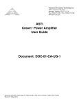
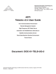
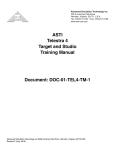
500 A Huntmar Park Drive
ASTi
Telestra 4
Quick Start Guide
Document: DOC-01-TEL4-QSG-1
Advanced Simulation Technology inc.500A Huntmar Park Drive, Herndon, Virginia, 20170 USA
Revision E (March, 2011)
Product Name: Telestra 4 Target and ACE Studio
ASTi Telestra 4 Quick Start Guide
© Copyright ASTi 2011. ASTi documents are continuously updated, see www.asti-usa.com/support/document.
Restricted Rights: Use, duplication, or disclosure by the Government is subject to restrictions as set forth in subparagraph (c)(1)(ii) of the Rights in Technical Data and Computer Software clause at DFARS 252.227-7013.
This material may be reproduced by or for the U.S. Government pursuant to the copyright license under the
clause at DFARS 252.227-7013 (1994).
ASTi
500-A Huntmar Park Drive
Herndon, VA 20170
Table of Contents
1.0. Purpose . . . . . . . . . . . . . . . . . . . . . . . . . . . . . . . . . . . . . . . . . . . . . . . 1
1.1. Top Level Hardware Layout ............................................................................. 1
1.2. Target Ethernet Port Connections .................................................................. 2
1.3. Studio and Target Networking ........................................................................ 3
1.3.1. Basic Requirements ................................................................................... 3
1.3.2. Basic Network Debugging .......................................................................... 5
2.0. Setting up the ACE Studio Development Workstation . . . . . . . . . 6
3.0. Setting up the Telestra 4 Target . . . . . . . . . . . . . . . . . . . . . . . . . . . 8
4.0. Setting up the Audio Distribution Hardware . . . . . . . . . . . . . . . . 11
5.0. Setting up the ACENet . . . . . . . . . . . . . . . . . . . . . . . . . . . . . . . . . . 13
6.0. Starting a New Project . . . . . . . . . . . . . . . . . . . . . . . . . . . . . . . . . . 14
i
ii
ASTi Telestra 4 Quick Start Guide (Ver. 1, Rev. E)
1.0. Purpose
The purpose of the Telestra 4 Quick Start Guide is to instruct new users from unpacking their
Telestra 4 equipment, to setup, to selecting and starting a new project.
Note: This document is a high-level “quick start” to using ASTi’s Telestra 4 equipment. Please
refer to each product’s individual guide for a comprehensive understanding of the equipment.
For essential Telestra 4 documentation, please see ASTi’s web site:
http://www.asti-usa.com/support/document/telestra4.html
1.1. Top Level Hardware Layout
ACE Studio
Development
Workstation
DIS
Target
Target
Eth0
Eth0
Eth1
Eth1
ACENet Switch
Amp (4ch.)
CAT 5 Cable
ACE-RIU
CHAN A
CHAN B
CHAN C
CHAN D
ACENet Switch
2 Channel ACU
Advanced Simulation Technology, Inc.
ACU2
PTT
Hand-Held
Terminal
Powered
Speaker
Commercial and
Military Headsets
PTT
SINCGARS
VCR or Other
Recording Devices
Please note not all hardware configurations are the same. The system setup will vary with customer applications.
Copyright © 2011 Advanced Simulation Technology inc.
1
ASTi Telestra 4 Quick Start (Ver. 1, Rev. E)
1.2. Target Ethernet Port Connections
Port
Connection
eth0
ASTiNet (network with Development Workstation)
eth1
ACENet (network with ACENet devices)
eth2
Host Connection
PROPERTY OF
ASTI
0000
Network Ports
See chassis labels for ethernet assignment
Ethernet labels will be Eth0, Eth1, and Eth2
Please read the Ethernet labels on your system to verify Ethernet locations.
For more information on the Ethernet Network Ports please see Chapter 3: System Installation Network Ports in the Target Operation and Maintenance Manual (DOC-01-TEL4-TUG-1).
2
Copyright © 2011 Advanced Simulation Technology inc.
ASTi Telestra 4 Quick Start Guide (Ver. 1, Rev. E)
1.3. Studio and Target Networking
1.3.1. Basic Requirements
When setting up the Target and Studio network configuration there are several requirements to
keep in mind in order for the Target and Studio to communicate over the network.
The following requirements are for the Studio and Target when they have the same subnet.
Target Networking Requirements
• Set basic IPv4 settings including valid IP address, netmask and gateway. If the network does
not have a gateway enter the IP address in the gateway field. See section “3.0. Setting up the
Telestra 4 Target” for step-by-step instructions.
• Set a valid unique hostname. This is set in RMS Configuration > Networking.
• Multiple Ethernet interfaces cannot be on the same subnet.
• Verify that there is a valid IPv6 link-local address. To view the IPv6 address in RMS navigate to the Configuration > Networking Devices page.
Studio Networking Requirements
• Set basic IPv4 settings including valid IP address, netmask and gateway. See section “2.0.
Setting up the ACE Studio Development Workstation” for step-by-step instructions.
• Multiple Ethernet interfaces cannot be on the same subnet.
• Verify that there is a valid IPv6 link-local address. To verify this type the following in a Studio terminal:
ifconfig
Studio Running on a Virtual Machine
• Set up the networking for the Host OS and the Guest OS.
• Do not use NAT mode. NAT mode is not supported by ASTi.
Copyright © 2011 Advanced Simulation Technology inc.
3
ASTi Telestra 4 Quick Start (Ver. 1, Rev. E)
Target and Studio on Different Subnets
The following instructions are for Studio and Target when they have different subnets or when the
Studio is connected over a WAN. In Studio, the Project will not populate in the list automatically,
you must follow the instructions below to open a Project. To open a Project in Studio, you must
know the Project name and Target name or use the RMS Project Management page to find the
URL.
1. In Project Manager under the Project menu select “Open URL...”
2. You are prompted to “Enter Project URL”.
3. Studio is expecting a URL in the following format:
https://x.x.x.x/projects/<ProjectName>
where x.x.x.x is the IP address. Do not use hostname.local.
4. In addition to typing in the URL, the links can also be copied from the Project Management section under RMS. You can copy the URL by right clicking on the Project links
(don’t forget to add the ‘https://’).
4
Copyright © 2011 Advanced Simulation Technology inc.
ASTi Telestra 4 Quick Start Guide (Ver. 1, Rev. E)
1.3.2. Basic Network Debugging
If possible, disable your firewall for debugging purposes.
Log into your Studio and open a terminal.
1. Try to ping the Target. Allow ping to run for a full 30 seconds to make sure there isn't an
intermittent networking problem. Type the following:
ping x.x.x.x
where x.x.x.x is the IP address.
2. Then type:
ping hostname.local
If this doesn't work, there is something wrong with your basic IPv4 settings. Check your
IPv4 settings. This also verifies that Avahi mDNS is running on the Target.
3. You can also verify mDNS by typing the following in a terminal:
netstat -gn
You should see “224.0.0.251” and the following string:
ff18:6e87:5466:0016:cba9:773f:4571:aced
Both of these need to appear on the interface (i.e. Eth0) you are using.
4. Type the following command:
ping6 -I <interface> ff18:6e87:5466:0016:cba9:773f:4571:aced
where <interface> is your interface i.e. eth0. This checks to see if Studio can see Target’s ANZAC information.
Log into your Target from a terminal and repeat the debugging steps above.
Copyright © 2011 Advanced Simulation Technology inc.
5
ASTi Telestra 4 Quick Start (Ver. 1, Rev. E)
2.0. Setting up the ACE Studio Development Workstation
To complete the set up you will need the following hardware:
• monitor
• keyboard
• mouse
• power supply (if using a small footprint computer system)
• ACE Studio Development Workstation
• Category 5e cable or better
• Network connection from ACE Studio to Target
Follow the steps below to setup the ACE Studio Development Workstation and assign an IP
address to the system. The ACE Studio Development Workstation will not have an IP address
without a DHCP network connection.
1. Connect the monitor, keyboard, mouse, and power supply to the development workstation.
2. Connect the development workstation to the same network as the Target.
3. Power on the development workstation and allow it to boot.
The development workstation will not have an IP address without a DHCP network connection.
4. In the top left corner select System > Administration > Network.
6
Copyright © 2011 Advanced Simulation Technology inc.
ASTi Telestra 4 Quick Start Guide (Ver. 1, Rev. E)
5. Check the ‘Profile’ box and then select ‘Edit.’
6. Select the ‘Statically set IP addresses’ button.
7. Enter the IP address and Subnet mask.
Ask your network administrator for valid IP addresses and subnet masks for the network(s) where the Target and ACE Studio Development Workstation will be integrated.
8. Enter the default gateway. If the network does not have a gateway, enter the IP address in
this field.
9. Reboot the Studio platform.
Copyright © 2011 Advanced Simulation Technology inc.
7
ASTi Telestra 4 Quick Start (Ver. 1, Rev. E)
3.0. Setting up the Telestra 4 Target
To complete the set up you will need the following hardware:
• monitor
• keyboard
• ACE Studio Development Workstation
• Category 5e cable or better
• Target
Follow the steps below to setup the Target and assign an IP address.
1. Connect the monitor and keyboard to the Target.
2. Using a Category 5e cable, connect the Target to the ASTiNet/DIS network using Eth0.
See “Top Level Hardware Layout” on page 1.
3. Power on the Target and allow it to boot.
4. Login with the following:
Username: root Password: abcd1234
5. The Target will not have an IP address without a DHCP network connection. To set an IP
address, type:
ace-net-config -a xxx.xxx.xxx.xxx -n yyy.yyy.yyy.yyy
where ‘x.x.x.x’ is the IP address and ‘y.y.y.y’ is the subnet mask.
This sets the IP address and netmask for Eth0 which is used to access the Remote Management System (RMS) via a web browser.
6. Optional: For more network setup options type:
ace-net-config -h
7. Once you have configured Eth0, you can use RMS to make additional changes to the network settings.
8. On the development workstation or any computer on the network with a web browser,
open a browser and in the address bar type in the IP address to open the Remote Management System (RMS).
Note: Depending on your web browser and browser version, the browser may show a
failed connection due to a self signed security certificate. Bypass the warning by following
the prompts to add a security exception.
8
Copyright © 2011 Advanced Simulation Technology inc.
ASTi Telestra 4 Quick Start Guide (Ver. 1, Rev. E)
9. In RMS, navigate to the Configuration > Network Devices page to set the remaining network interfaces.
To access the network interfaces you are required to log in to RMS. Enter the default username and password.
Username: admin Password: astirules
Copyright © 2011 Advanced Simulation Technology inc.
9
ASTi Telestra 4 Quick Start (Ver. 1, Rev. E)
10.Navigate to the Configuration > Networking page and verify the following is set for
your system networking:
Default Route
Gateway IP
Domain (optional, leave blank if none)
Hostname
Nameserver (optional, leave blank if none)
11.Navigate to the ‘System Actions’ page (System > Reset/Power) and select ‘System
Reboot.’ The reboot process will take approximately 2 minutes, select the ‘Reboot Telestra System Now’ button.
10
Copyright © 2011 Advanced Simulation Technology inc.
ASTi Telestra 4 Quick Start Guide (Ver. 1, Rev. E)
4.0. Setting up the Audio Distribution Hardware
To complete the set up you will need the following hardware:
• ACU2, ACU, or ACE-RIU
• Power supply
• ACE Studio Development Workstation
• Category 5e cable or better
• ACENet switch
Follow the steps below to set up the ACENet audio distribution device.
1. Using a Category 5 cable connect the ACENet switch to the Ethernet port on the device.
Note there are two Ethernet ports on the ACU, select either one.
Power
ACU Rear Panel
ACENet Ports
Serial Ports
ACEnet ACEnet
ACU Status Channel Status
Indicators
Indicators
Power Serial Ports
ACENet
Serial Ports
B
A
Status
ACENet
Power
ACE-RIU Rear Panel
1234
+15VDC
Status
Power
ACU2 Rear Panel
Power
Out
Power
In
Serial Ports
ACENet
Serial Ports
2
1
Status
ACENet
1234
+15VDC
Status Indicators
2. Power on the device.
3. Using a Category 5 cable connect the ACENet switch to eth1 on the Target. See Top Level
Hardware Layout on page 1.
Copyright © 2011 Advanced Simulation Technology inc.
11
ASTi Telestra 4 Quick Start (Ver. 1, Rev. E)
4. On the development station or a computer on the network with a web browser, open the
browser and in the address bar type the IP address of eth0 on the Target into the browser.
Note: Depending on your web browser and browser version, the browser may show a
failed connection due to a self signed security certificate. Bypass the warning by following
the prompts to add a security exception.
5. The main RMS page will open in the browser.
6. Select Network > ACUs, ACU2s, or ACE-RIU and the device(s) connected to the
ACENet switch should appear on the main device(s) page, as shown below.
12
Copyright © 2011 Advanced Simulation Technology inc.
ASTi Telestra 4 Quick Start Guide (Ver. 1, Rev. E)
5.0. Setting up the ACENet
The ACENet infrastructure requires a closed network with only Telestra 4 equipment connected
including Targets, audio distribution devices and ACENet compatible equipment. All ACENet
switches must be gigabit capable and all cabling connections must be Category 5e grade or better.
Please refer to the Top Level Hardware Layout for an ACENet setup example with peripherals.
Please refer to the ACENet User Guide (DOC-01-TELS4-AN-UG-1) for complete requirements,
recommended switches, and frequently asked questions.
Copyright © 2011 Advanced Simulation Technology inc.
13
ASTi Telestra 4 Quick Start (Ver. 1, Rev. E)
6.0. Starting a New Project
Follow the steps below to start a new Project on the ACE Studio
Development Workstation.
1. On the development workstation, select ‘Applications’
from the top left tool bar.
2. Select ‘ASTi’ and then select ‘ACE Studio.’ The Project Manager will open.
3. In the top left tool bar select Project > Open.
4. Open the Project dialogue box, select your local Target’s
name, and press the ‘+’ symbol to add a new Project.
5. ACE Studio Project Manager opens and on the left side of
the screen is the new Project and below that is ‘Main.’
6. Click ‘Main’ to open the graphical view of the Project, as
shown below.
7. Select the install layout icon.
8. Right-click on the Target icon and select ‘Open,’ this will open ACE Studio Load Viewer.
14
Copyright © 2011 Advanced Simulation Technology inc.
ASTi Telestra 4 Quick Start Guide (Ver. 1, Rev. E)
9. Right-click in the window titled ‘Main’ and add SimModel (for example). After selecting
an item, the screen will display ‘Added Successfully.’ Then select ‘cancel’ to close the
window.
10.Double-click on the Sim Model icon inserted in the previous step. In the External Connections Box, right-click and select ‘Add,’ to pick an item such as Audio > Vox. This will
add the audio_vox component to the model.
Copyright © 2011 Advanced Simulation Technology inc.
15
ASTi Telestra 4 Quick Start (Ver. 1, Rev. E)
11.At the top right, the audio_vox component is listed under components. Click ‘view’ and a
screen with the variables for the Vox object will appear.
After becoming familiar with ACE Studio software, the user can continue to add objects and create models to meet their requirements1.
1ASTi
recommends a three-day training course which includes intensive hardware and software
familiarization, and Model Building assistance oriented to the customer’s application.
Please see the ACE Studio User Guide (DOC-01-TELAS-UG-4) to test the setup with the ACE
Readiness Test. The Readiness Test is a simple model available on the system to test each channel
of the audio distribution devices. The Readiness Test is also useful when troubleshooting.
16
Copyright © 2011 Advanced Simulation Technology inc.