1
2
ATA Interface Reference Manual, Rev. C
ing specific configuration of the drive’s features for specialized applications.
1.2 Origins and implementation history
The ATA interface has evolved rapidly since its initial design by Compaq
Corporation. After refining the basic ATA interface concepts and circuitry,
Compaq Corporation worked with Imprimis (now a part of Seagate) to
build the first ATA interface drive. At this stage, the interface was far from
being an accepted standard. However, it was a natural extension of the
ATA I/O bus, and gained industry-wide acceptance because most of the
necessary framework needed for the implementation was already present in the host machine.
Initially, there were no industry-wide standards for implementing the ATA
interface, leaving manufacturers free to extend and improve upon it. In
the latter part of 1988, a Common Access Method (CAM) committee was
established to develop such standards. Their results were adopted by
the American National Standards Institute (ANSI) with the intent of
creating a common ATA command specification.
The ANSI standard for the ATA interface now provides specifications for
mandatory commands, signal conventions, register descriptions and
other information necessary for basic compatibility across manufacturers
and platforms. The current ANSI specification includes provisions for
extended features such as caching and power management, while also
providing options for vendor-specific enhancements.
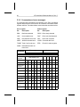
1.3 Nomenclature and conventions
Throughout this manual, the term master refers to Drive 0 in a two-drive
system; the term slave refers to Drive 1, if present (for more information
see Section 2.3).
Signal names are shown in all capital letters. Signals may be asserted
or negated. A signal that is asserted as a higher positive voltage is
referred to as active high. A signal that is asserted as a lower (positive)
voltage is referred to as active low, and is indicated by a minus sign (–)
following the signal name. Bit names are in all capitals except where a
lower case “n” precedes the name, as the case of nIEN. The “n” indicates
that when the bit is cleared (= 0), the action is true and when the bit is
set (= 1), the action is false. For example, BIT =1 and nBIT = 0 would be
true; BIT = 0 and nBIT = 1 would be false.